rexroth indradrive edition 06 drive systems with … · project planning manual electric drives and...
TRANSCRIPT

Project Planning Manual
Electric Drivesand Controls Pneumatics Service
Linear Motion and Assembly TechnologiesHydraulics
Rexroth IndraDriveDrive Systems with HMV01/02HMS01/02, HMD01, HCS02/03
R911309636Edition 06

Rexroth IndraDriveDrive Systems with HMV01/02HMS01/02, HMD01, HCS02/03
Project Planning Manual
DOK-INDRV*-SYSTEM*****-PR06-EN-P
RS-133519800a6846ac00a015a26f840210-5-en-US-3
Edition Release Date Notes
04 08/2007 -05 09/2009 -06 08/2013 Changes: See index en‐
try "Changes"
Copyright © Bosch Rexroth AG 2013This document, as well as the data, specifications and other information setforth in it, are the exclusive property of Bosch Rexroth AG. It may not be re‐produced or given to third parties without its consent.
Liability The specified data is intended for product description purposes only and shallnot be deemed to be a guaranteed characteristic unless expressly stipulatedin the contract. All rights are reserved with respect to the content of this docu‐mentation and the availability of the product.
Published by Bosch Rexroth AGBgm.-Dr.-Nebel-Str. 2 ■ 97816 Lohr a. Main, GermanyPhone +49 9352 18 0 ■ Fax +49 9352 18 8400http://www.boschrexroth.com/DC-IA/EDH1 (DH); DC-IA/EDY1 (RB/US/BB)
Title
Type of Documentation
Document Typecode
Internal File Reference
Record of Revision
Bosch Rexroth AG DOK-INDRV*-SYSTEM*****-PR06-EN-P Rexroth IndraDrive Drive Systems with HMV01/02 HMS01/02, HMD01, HCS02/03

Table of ContentsPage
1 System Presentation.................................................................................................... 111.1 System Platform................................................................................................................................... 111.2 Drive System Rexroth IndraDrive C - Compact Converters................................................................. 121.3 Drive System Rexroth IndraDrive M - Modular System........................................................................ 141.4 Drive System Rexroth IndraDrive Mi.................................................................................................... 171.4.1 Drive Systems with KCU01............................................................................................................... 171.4.2 Drive Systems with KCU02............................................................................................................... 201.5 Combinations of Rexroth IndraDrive C with Rexroth IndraDrive M and Rexroth IndraDrive Mi........... 241.6 Basic Design of the Devices................................................................................................................. 241.6.1 General Information........................................................................................................................... 241.6.2 Power Section................................................................................................................................... 241.6.3 Control Section.................................................................................................................................. 251.7 Overview of Type Currents and Type Performances............................................................................ 261.7.1 General Information........................................................................................................................... 261.7.2 Drive Controllers................................................................................................................................ 261.7.3 Supply Units and Converters............................................................................................................. 271.8 Overview of Functions.......................................................................................................................... 281.8.1 Supply Units and Power Sections..................................................................................................... 281.8.2 Control Sections................................................................................................................................ 281.9 Documentations.................................................................................................................................... 281.9.1 About This Documentation................................................................................................................ 281.9.2 Overview of Documentations............................................................................................................. 29
Drive Systems, System Components............................................................................................. 29Motors............................................................................................................................................. 30Cables............................................................................................................................................ 31Firmware......................................................................................................................................... 31
1.9.3 Your Feedback.................................................................................................................................. 34
2 Important Directions for Use ....................................................................................... 352.1 Appropriate Use ................................................................................................................................... 352.1.1 Introduction........................................................................................................................................ 352.1.2 Areas of Use and Application............................................................................................................ 352.2 Inappropriate Use................................................................................................................................. 36
3 Safety Instructions for Electric Drives and Controls..................................................... 373.1 Definitions of Terms.............................................................................................................................. 373.2 General Information.............................................................................................................................. 383.2.1 Using the Safety Instructions and Passing Them on to Others......................................................... 383.2.2 Requirements for Safe Use............................................................................................................... 383.2.3 Hazards by Improper Use.................................................................................................................. 393.3 Instructions with Regard to Specific Dangers....................................................................................... 403.3.1 Protection Against Contact with Electrical Parts and Housings......................................................... 403.3.2 Protective Extra-Low Voltage as Protection Against Electric Shock ................................................ 41
DOK-INDRV*-SYSTEM*****-PR06-EN-P Rexroth IndraDrive Drive Systems with HMV01/02 HMS01/02, HMD01, HCS02/03
Bosch Rexroth AG I/309
Table of Contents
Page
3.3.3 Protection Against Dangerous Movements....................................................................................... 423.3.4 Protection Against Magnetic and Electromagnetic Fields During Operation and Mounting.............. 433.3.5 Protection Against Contact with Hot Parts......................................................................................... 443.3.6 Protection During Handling and Mounting......................................................................................... 443.3.7 Battery Safety.................................................................................................................................... 443.3.8 Protection Against Pressurized Systems........................................................................................... 453.4 Explanation of Signal Words and the Safety Alert Symbol................................................................... 45
4 Brief Description, Usage.............................................................................................. 474.1 General Information.............................................................................................................................. 474.2 Applications of the Drive System Rexroth IndraDrive........................................................................... 474.3 Mains Transformers DST and DLT....................................................................................................... 474.4 Mains Filters HNF, HNK, NFE, HNS02 and NFD................................................................................. 474.5 Mains Chokes HNL01 and HNL02........................................................................................................ 484.6 Supply Units HMV01 / HMV02.............................................................................................................. 494.7 Drive Controllers HMS01, HMS02 and HMD01.................................................................................... 494.8 Control Sections CSB, CSE, CSH, CDB.............................................................................................. 494.9 Drive Controllers HCS02...................................................................................................................... 504.10 Drive Controllers HCS03...................................................................................................................... 504.11 Components KCU, KSM, KMS............................................................................................................. 504.12 DC Bus Resistor Unit HLB01................................................................................................................ 514.13 Braking Resistor HLR01....................................................................................................................... 514.14 DC Bus Capacitor Unit HLC01............................................................................................................. 524.15 Fan Unit HAB01.................................................................................................................................... 524.16 Motor Filters HMF01............................................................................................................................. 524.17 Accessories HAS.................................................................................................................................. 524.18 Housing for Control Sections HAC01................................................................................................... 524.19 Hall Sensor Box SHL............................................................................................................................ 52
5 General Data and Specifications................................................................................. 555.1 Acceptance Tests and Approvals......................................................................................................... 555.2 Transport and Storage.......................................................................................................................... 575.2.1 Transport of the Components............................................................................................................ 575.2.2 Storage of the Components............................................................................................................... 585.3 Installation Conditions........................................................................................................................... 585.3.1 Ambient and Operating Conditions.................................................................................................... 585.3.2 Mounting Position.............................................................................................................................. 62
Mounting Positions of Components................................................................................................ 62Mounting Positions of Motor-Integrated Servo Drives.................................................................... 63
5.3.3 Compatibility With Foreign Matters.................................................................................................... 635.3.4 Motor Paint Coat................................................................................................................................ 645.4 Voltage Test and Insulation Resistance Test....................................................................................... 645.5 Control Voltage (24V Supply) .............................................................................................................. 65
Bosch Rexroth AG DOK-INDRV*-SYSTEM*****-PR06-EN-P Rexroth IndraDrive Drive Systems with HMV01/02 HMS01/02, HMD01, HCS02/03
II/309
Table of Contents
Page
6 Project Planning of Control Voltage (24V Supply)....................................................... 676.1 General Information.............................................................................................................................. 676.2 Selecting the 24V Supply...................................................................................................................... 676.2.1 General Information........................................................................................................................... 676.2.2 Electrical Requirements..................................................................................................................... 686.3 Installing the 24V Supply...................................................................................................................... 706.4 Looping Through the Control Voltage Supply....................................................................................... 71
7 Project Planning of Mains Connection ........................................................................ 737.1 General Information.............................................................................................................................. 737.2 Mains Voltage Supply .......................................................................................................................... 737.3 Mains Types......................................................................................................................................... 767.3.1 TN-S Mains Type............................................................................................................................... 767.3.2 TN-C Mains Type.............................................................................................................................. 767.3.3 IT Mains Type.................................................................................................................................... 777.3.4 TT System......................................................................................................................................... 787.3.5 Mains Grounded via Outer Conductor (Corner-Grounded Delta Mains)........................................... 797.4 Mains Short-Circuit Power and Mains Connected Load ...................................................................... 797.4.1 General Information........................................................................................................................... 797.4.2 Mains Short-Circuit Power................................................................................................................. 807.4.3 Mains Connected Load...................................................................................................................... 817.5 Protection Systems at the Mains Connection....................................................................................... 847.5.1 General Information........................................................................................................................... 847.5.2 Protective Grounding......................................................................................................................... 85
General Information........................................................................................................................ 85Fusing by Protective Grounding in TN-S Mains............................................................................. 86Fusing by Protective Grounding in TN-C Mains............................................................................. 87Fusing by Protective Grounding in IT Mains (Ungrounded Mains)................................................. 88
7.5.3 Connection for the Equipment Grounding Conductor........................................................................ 89General Information........................................................................................................................ 89Equipment Grounding Connection Between the Components....................................................... 89Connecting Equipment Grounding Conductor to Mains................................................................. 89
7.5.4 Residual-Current-Operated Circuit Breakers (RCD, RCCB) as Additional Fusing............................ 89General Information........................................................................................................................ 89Cause of Leakage Currents............................................................................................................ 90Possibilities of Use......................................................................................................................... 90Using Residual-Current-Operated Circuit Breakers at HCS Drive Controllers............................... 91Using Residual-Current-Operated Circuit Breakers at HMV Supply Units..................................... 92
7.5.5 Insulation Monitoring Devices............................................................................................................ 92
8 Configuring the Drive System...................................................................................... 938.1 General Information.............................................................................................................................. 938.2 Type of Supply for Power Sections....................................................................................................... 938.2.1 General Information........................................................................................................................... 938.2.2 HMV Supply Units for HMS/HMD Power Sections............................................................................ 96
DOK-INDRV*-SYSTEM*****-PR06-EN-P Rexroth IndraDrive Drive Systems with HMV01/02 HMS01/02, HMD01, HCS02/03
Bosch Rexroth AG III/309
Table of Contents
Page
Central Supply HMV....................................................................................................................... 96Parallel Operation HMV - Group Supply with DC Bus Connection HMV01, HMV02...................... 98
8.2.3 Converter HCS as Supply Unit.......................................................................................................... 99General Information........................................................................................................................ 99Central Supply - HCS Supply HCS or HMS/HMD Drive Controllers.............................................. 99Parallel Operation HCS - Group Supply with DC Bus Connection of the Groups........................ 102
8.2.4 Third-Party Supply Units.................................................................................................................. 105General Information...................................................................................................................... 105
8.3 Mains Connection Supply Units and Converters................................................................................ 1068.3.1 General Information......................................................................................................................... 1068.3.2 Mains Connection of HMV Supply Units.......................................................................................... 109
Mains Connection of HMV Supply Units - Additional Components.............................................. 109Mains Connection of HMV01.1E Supply Units............................................................................. 110Mains Connection of HMV01.1R Supply Units............................................................................. 111Mains Connection of HMV02.1R Supply Units............................................................................. 112
8.3.3 Mains Connection for HCS Converters........................................................................................... 113Mains Connection for HCS Converters - Additional Components................................................ 113Mains Connection for HCS02 Converters.................................................................................... 114Mains Connection for HCS03 Converters.................................................................................... 116
8.4 Additional Components....................................................................................................................... 1208.4.1 Additional Components at the DC Bus............................................................................................ 120
General Information...................................................................................................................... 120HLR Braking Resistors and DC Bus Resistor Units HLB............................................................. 122
8.4.2 Additional Components at the Motor Output................................................................................... 125General Information...................................................................................................................... 125HMF01 Motor Filters..................................................................................................................... 126
8.5 Power Section, Control Section, Firmware ........................................................................................ 1268.5.1 General Information......................................................................................................................... 1268.5.2 Power Section - Control Section...................................................................................................... 1278.5.3 Control Section - Firmware ............................................................................................................. 1278.5.4 Power Section - Firmware............................................................................................................... 1288.5.5 Motor - Firmware ............................................................................................................................ 1338.5.6 Encoder System - Encoder Evaluation............................................................................................ 1338.6 Combination With Other Rexroth Components.................................................................................. 1368.6.1 Combination With Components of the Control Range Rexroth IndraControl V............................... 136
Operator Terminals VCP.............................................................................................................. 1368.6.2 sercos Analog Converter................................................................................................................. 136
General Information...................................................................................................................... 136sercos Analog Converter.............................................................................................................. 136
8.7 Connection Cables to Motor............................................................................................................... 1378.7.1 General Information......................................................................................................................... 1378.7.2 Motor cable...................................................................................................................................... 137
General Information...................................................................................................................... 137Motor Cable Selection ................................................................................................................. 138Allowed Length of Motor Cable.................................................................................................... 138Voltage Drop on Connection to Motor Holding Brake................................................................... 139
Bosch Rexroth AG DOK-INDRV*-SYSTEM*****-PR06-EN-P Rexroth IndraDrive Drive Systems with HMV01/02 HMS01/02, HMD01, HCS02/03
IV/309
Table of Contents

Page
Mechanical Requirements............................................................................................................ 139Third-Party Power Cables............................................................................................................ 139
8.7.3 Encoder Cables .............................................................................................................................. 1408.8 Using Rexroth IndraDyn Motors......................................................................................................... 1408.8.1 Rexroth IndraDyn H – Synchronous Kit Spindle Motors.................................................................. 140
9 Circuits for the Mains Connection.............................................................................. 1419.1 General Information............................................................................................................................ 1419.2 Mains Contactor, Bb Contact.............................................................................................................. 1419.3 Circuits for Mains Connection of Rexroth IndraDrive C Drive Controllers.......................................... 1459.3.1 General Information......................................................................................................................... 1459.3.2 Control of External Mains Contactor for HCS02 and HCS03.......................................................... 145
General Information...................................................................................................................... 145Standard Design for HCS02 and HCS03 Drive Controllers.......................................................... 146Design for HCS02 and HCS03 Drive Controllers with Integrated 24V Control Voltage Supply. . . 147
9.3.3 Circuits HCS02 and HCS03 with DC Bus Resistor Unit HLB01.1C or HLB01.1D........................... 1489.4 Circuits for Mains Connection of Rexroth IndraDrive M Supply Units................................................ 1549.4.1 General Information......................................................................................................................... 1549.4.2 Parallel Operation HMV01............................................................................................................... 1559.4.3 Deceleration in the Case of Disturbed Electronic System of Drive (DC Bus Short Circuit is Activated)
......................................................................................................................................................... 155General Information...................................................................................................................... 155Control Circuits With DC Bus Short Circuit (ZKS)........................................................................ 157
9.4.4 Deceleration in the Case of Emergency Stop or Mains Failure....................................................... 166General Information...................................................................................................................... 166Control Circuit "Position-Controlled Deceleration by the Control Unit" without DC Bus Short Circuit(ZKS)............................................................................................................................................ 167Control Circuit Emergency Stop Relay without DC Bus Short Circuit (ZKS) ............................... 169
9.4.5 Signal Sequences When Switching HMV Supply Units ON and OFF............................................. 177Switching On................................................................................................................................ 177Switching Off................................................................................................................................ 179
10 Electromagnetic Compatibility (EMC)........................................................................ 18110.1 EMC Requirements............................................................................................................................ 18110.1.1 General Information......................................................................................................................... 18110.1.2 Noise Immunity in the Drive System................................................................................................ 181
Basic Structure for Noise Immunity.............................................................................................. 181Limit Values for Noise Immunity................................................................................................... 182
10.1.3 Noise Emission of the Drive System............................................................................................... 182Causes of Noise Emission............................................................................................................ 182Limit Values for Line-Based Disturbances.................................................................................... 183
10.2 Ensuring the EMC Requirements....................................................................................................... 18610.3 Measures to Reduce Noise Emission................................................................................................. 18710.3.1 General Information......................................................................................................................... 18710.3.2 Shielding.......................................................................................................................................... 18710.3.3 Grounding........................................................................................................................................ 187
DOK-INDRV*-SYSTEM*****-PR06-EN-P Rexroth IndraDrive Drive Systems with HMV01/02 HMS01/02, HMD01, HCS02/03
Bosch Rexroth AG V/309
Table of Contents
Page
10.3.4 Filtering............................................................................................................................................ 187
11 Arranging the Components in the Control Cabinet ................................................... 18911.1 Dimensions and Distances................................................................................................................. 18911.1.1 Main Dimensions of the System Components................................................................................. 189
General Information...................................................................................................................... 189Device Depths and Device Heights.............................................................................................. 189
11.1.2 Distances......................................................................................................................................... 190General Information...................................................................................................................... 190Distance Between the Devices..................................................................................................... 190Distance to the Bottom of the Devices......................................................................................... 191Distance to the Top of the Devices............................................................................................... 191Lateral Distance at Drive System................................................................................................. 193
11.1.3 Boring Dimensions for the Mounting Plate...................................................................................... 194Individually Arranged Devices...................................................................................................... 194Combination of Devices of the Rexroth IndraDrive M Product Range......................................... 196Combination of Drive Controllers of the Rexroth IndraDrive C Product Range............................ 199Combination of Drive Controllers of the Rexroth IndraDrive C and M Product Ranges............... 200
11.2 Arranging Components From Electrical Point of View........................................................................ 20111.2.1 General Information......................................................................................................................... 20111.2.2 Performance-Dependent Arrangement .......................................................................................... 20211.2.3 EMC Measures for Design and Installation..................................................................................... 203
Rules for Design of Installations With Drive Controllers in Compliance With EMC...................... 203EMC-Optimal Installation in Facility and Control Cabinet............................................................. 204Ground Connections..................................................................................................................... 211Installing Signal Lines and Signal Cables..................................................................................... 212General Measures of Radio Interference Suppression for Relays, Contactors, Switches, Chokesand Inductive Loads..................................................................................................................... 212
12 Project Planning of Cooling System........................................................................... 21512.1 Control Cabinet................................................................................................................................... 21512.1.1 Control Cabinet Design and Cooling............................................................................................... 21512.1.2 Arranging the Cooling Units............................................................................................................. 21612.1.3 Multiple-Line Design of the Control Cabinet.................................................................................... 218
13 Connections of the Components in the Drive System............................................... 22113.1 System Connections of the Components........................................................................................... 22113.1.1 General Information......................................................................................................................... 22113.1.2 Position of System Connections...................................................................................................... 22213.1.3 Ground Connection of Housing....................................................................................................... 22213.1.4 Connection Point of Equipment Grounding Conductor and Equipment Grounding Connections.... 223
General Information...................................................................................................................... 223Equipment Grounding Connections Between Devices................................................................. 224Connection to Equipment Grounding System in Control Cabinet................................................. 225
13.1.5 Connection to Mains Choke and Mains Filter ................................................................................. 226
Bosch Rexroth AG DOK-INDRV*-SYSTEM*****-PR06-EN-P Rexroth IndraDrive Drive Systems with HMV01/02 HMS01/02, HMD01, HCS02/03
VI/309
Table of Contents

Page
13.1.6 Connection of the DC Bus Connections.......................................................................................... 228General Information...................................................................................................................... 228Minimum Requirements to Connection Lines............................................................................... 229Maximum Allowed Line Length at DC Bus Connection................................................................ 230Cable Routing to the Left.............................................................................................................. 231Cable Routing to the Right........................................................................................................... 231
13.1.7 Connection of the Control Voltage Connections.............................................................................. 232General Information...................................................................................................................... 232Cable Routing to the Left.............................................................................................................. 234Cable Routing to the Right........................................................................................................... 235
13.1.8 Module Bus Connection X1............................................................................................................. 23513.1.9 Connection of Motor to Drive Controller.......................................................................................... 236
General Information...................................................................................................................... 236Shield Connection with Accessory HAS02................................................................................... 237Shield Connection without Accessory HAS02.............................................................................. 237
13.2 Overall Connection Diagrams of Drive Systems................................................................................. 240
14 Third-Party Motors at Rexroth IndraDrive Controllers................................................ 24114.1 General Information on Third-Party Motors........................................................................................ 24114.1.1 Why Use Third-Party Motors at Rexroth IndraDrive Controllers?.................................................... 24114.1.2 Which are the Important Directives?............................................................................................... 24114.1.3 Third-Party Motors to be Controlled................................................................................................ 24114.2 Requirements on Third-Party Motors.................................................................................................. 24214.2.1 General Information......................................................................................................................... 24214.2.2 Voltage Load of the Third-Party Motor ........................................................................................... 24214.2.3 Minimum Inductance of Third-Party Motor...................................................................................... 24314.2.4 Temperature Evaluation of Third-Party Motor................................................................................. 24414.3 Requirements on the Encoder of the Third-Party Motor..................................................................... 24514.3.1 Motor Encoder of Asynchronous Third-Party Motor........................................................................ 24514.3.2 Motor Encoder of Synchronous Third-Party Motor.......................................................................... 24514.3.3 Motor Encoder Resolver - Notes on Selection................................................................................ 24514.4 Notes on Selection and Commissioning............................................................................................. 24514.4.1 Selecting the Controller as Regards Continuous Current................................................................ 24514.4.2 Selecting the Connection Technique............................................................................................... 24614.4.3 Notes on Commissioning................................................................................................................. 246
15 Calculations............................................................................................................... 24715.1 Determining the Appropriate Drive Controller..................................................................................... 24715.1.1 Introduction...................................................................................................................................... 24715.1.2 DC Bus Continuous Power.............................................................................................................. 24715.1.3 DC Bus Peak Power........................................................................................................................ 25115.1.4 Regenerative Power........................................................................................................................ 25115.1.5 Reduction of Generated Power Dissipation - Additional External Capacitors at DC Bus................ 25215.1.6 Continuous Regenerative Power..................................................................................................... 25515.1.7 Peak Regenerative Power............................................................................................................... 257
DOK-INDRV*-SYSTEM*****-PR06-EN-P Rexroth IndraDrive Drive Systems with HMV01/02 HMS01/02, HMD01, HCS02/03
Bosch Rexroth AG VII/309
Table of Contents

Page
15.1.8 Calculating the Control Factor......................................................................................................... 25815.2 Calculations for the Mains Connection............................................................................................... 26015.2.1 Calculating the Mains-Side Phase Current ..................................................................................... 26015.2.2 Calculating the Inrush Current......................................................................................................... 26115.2.3 Calculations for the Mains Harmonics............................................................................................. 261
Harmonic Load THD..................................................................................................................... 261Harmonic Content / Distortion Factor k........................................................................................ 261Power Factor cosφ1 or DPF for Calculating the Wattless Power Load of the Mains................... 262Power Factor cosφ or TPF (λ)...................................................................................................... 262
15.2.4 Mains Voltage Unbalance................................................................................................................ 26215.2.5 Calculating the Allowed Continuous Power in the Common DC Bus.............................................. 26315.3 Determining Components in the Mains Connection........................................................................... 26415.3.1 Determining the Mains Choke......................................................................................................... 26415.3.2 Determining the Mains Filter............................................................................................................ 26415.3.3 Determining Mains Transformer DLT.............................................................................................. 26515.3.4 Mains Contactor and Fusing ........................................................................................................... 26515.3.5 Dimensioning the Line Cross Sections and Fuses ......................................................................... 26615.3.6 Determining the Leakage Capacitance........................................................................................... 27215.3.7 Determining the Allowed Operating Data of Mains Filters............................................................... 273
Reducing Allowed Operating Voltage Depending on Actual Temperature Rise Due to Harmonics...................................................................................................................................................... 273Current Reduction in the Case of Overtemperature..................................................................... 274
15.4 Other Calculations.............................................................................................................................. 27615.4.1 Charging the DC Bus....................................................................................................................... 27615.4.2 Calculating Speed Characteristic and Braking Time With DC Bus Short Circuit (ZKS).................. 277
16 Environmental Protection and Disposal .................................................................... 28116.1 Environmental Protection.................................................................................................................... 28116.2 Disposal.............................................................................................................................................. 281
17 Service and Support.................................................................................................. 283
18 Appendix.................................................................................................................... 28518.1 System Elements - Product Overview, Short Designations................................................................ 28518.2 Leakage Capacitances....................................................................................................................... 28718.2.1 Leakage Capacitance of Motors...................................................................................................... 28718.2.2 Leakage Capacitance of Power Cables ......................................................................................... 28818.3 Emitted Harmonics on Mains Current and Mains Voltage.................................................................. 29018.3.1 General Information......................................................................................................................... 29018.3.2 Harmonics of Mains Current............................................................................................................ 29018.3.3 Harmonics on Mains Voltage........................................................................................................... 29418.4 Voltage Pulse for Test According to EN61000................................................................................... 29418.5 Discharging of Capacitors................................................................................................................... 29618.5.1 Discharging DC Bus Capacitors...................................................................................................... 296
Bosch Rexroth AG DOK-INDRV*-SYSTEM*****-PR06-EN-P Rexroth IndraDrive Drive Systems with HMV01/02 HMS01/02, HMD01, HCS02/03
VIII/309
Table of Contents

Page
Glossary, Definitions of Terms, Abbreviations .......................................................... 297
Index.......................................................................................................................... 301
DOK-INDRV*-SYSTEM*****-PR06-EN-P Rexroth IndraDrive Drive Systems with HMV01/02 HMS01/02, HMD01, HCS02/03
Bosch Rexroth AG IX/309
Table of Contents

Bosch Rexroth AG DOK-INDRV*-SYSTEM*****-PR06-EN-P Rexroth IndraDrive Drive Systems with HMV01/02 HMS01/02, HMD01, HCS02/03
X/309

1 System Presentation1.1 System Platform
The following products are part of the Rexroth IndraDrive system platform:
Platform Rexroth IndraDrive
Control sections Power sections Supply units Additionalcompo‐nents
Motor-integra‐ted / near mo‐tor drive tech‐
nology
EconomyC*E
Single-axis
BasicC*B
Single-axis/double-axis
AdvancedC*H
Single-axis
ModularHM*
Single-axis/double-axis
CompactHC*
Single-axis
HMV-E HMV-R HNFHNLHLBHLCHLR
KCUKSMKMS
Tab.1-1: Rexroth IndraDrive System PlatformHierarchical Levels of Rexroth
IndraDriveThe assignment of the fundamental components to the hierarchical levelssystem platform, type, range, series and component is illustrated in the figurebelow.
Platform Rexroth IndraDrive
Type Rexroth IndraDrive power sections Rexroth IndraDrive controlsections
Range Rexroth IndraDrive C Rexroth IndraDrive M Economy Basic Advanced
Series HCS01 HCS02 HCS03 HCS04 HMV01HMV02
HMS01HMS02
HMD01 CSE CSBCDB
CSH
Component W0003...W0054
W0012…W0070
W0070…W0210
W0350…W1540
W0015…W0120
W0020…W0350
W0012…W0036
02 0102
0102
Tab.1-2: Hierarchical Levels Rexroth IndraDrive C and M
Platform Rexroth IndraDrive
Type Rexroth IndraDrive motor-integrated servo drives
Rexroth IndraDrive nearmotor servo drives
Rexroth IndraDrive,drive connection box
Rexroth cables
Range Rexroth IndraDrive Mi Hybrid cable
Series KSM01, KSM02 KMS01, KMS02 KCU01, KCU02 RKHxxxx
Component Different sizes, lengthsand designs
KMS01.2B-A018KMS02.1B-A018
KCU01.2N-SE-SE*-025-NN-S
KCU02.1N-ET-ET*-025-NN-N
Different lengths andcodings
Tab.1-3: Hierarchical Levels Rexroth IndraDrive Mi
Short Designations For an overview of the short designations, such as HMV, HCS, CSH, KCU,etc., see Appendix of this documentation, chapter 18.1 System Elements -Product Overview, Short Designations, page 285.
DOK-INDRV*-SYSTEM*****-PR06-EN-P Rexroth IndraDrive Drive Systems with HMV01/02 HMS01/02, HMD01, HCS02/03
Bosch Rexroth AG 11/309
System Presentation

1.2 Drive System Rexroth IndraDrive C - Compact ConvertersRexroth IndraDrive C is the compact converter type of the Rexroth IndraDriveproduct range.Basic features of the product range Rexroth IndraDrive C:● Integrated power supply● Integrated braking resistor (as an option, external for HCS03)● Integrated inverters● Integrated 24V control voltage supply (optional for HCS02)● Additional components:
– DC bus resistor units– DC bus capacitor units– Braking resistors
The figure below illustrates the system structure of the drive systemRexroth IndraDrive C. Allowed combinations of components: See chapter 8 "Configuring the Drive System" on page 93
Bosch Rexroth AG DOK-INDRV*-SYSTEM*****-PR06-EN-P Rexroth IndraDrive Drive Systems with HMV01/02 HMS01/02, HMD01, HCS02/03
12/309
System Presentation
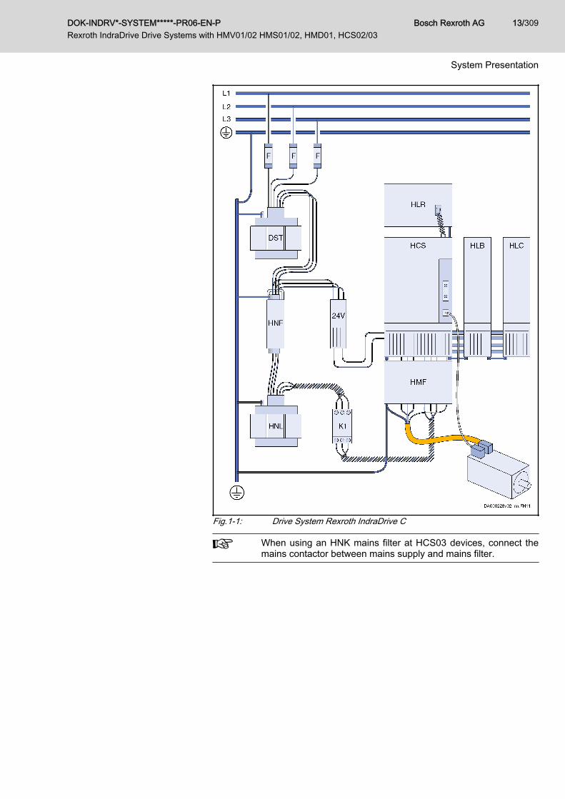
Fig.1-1: Drive System Rexroth IndraDrive C
When using an HNK mains filter at HCS03 devices, connect themains contactor between mains supply and mains filter.
DOK-INDRV*-SYSTEM*****-PR06-EN-P Rexroth IndraDrive Drive Systems with HMV01/02 HMS01/02, HMD01, HCS02/03
Bosch Rexroth AG 13/309
System Presentation

1.3 Drive System Rexroth IndraDrive M - Modular SystemRexroth IndraDrive M is the modular system type of the Rexroth IndraDriveproduct range.The combination of an HMV supply unit and HMS and HMD drive controllersto form a modular drive system allows operating several motors.Basic features of the product range Rexroth IndraDrive M:● Scaleable power supply● Integrated mains contactor (except for HMV01.1R-W0120)● Modular extension of number of axes is possible● Two series (mounting depths) of HMV and HMS available● Additional components:
– DC bus resistor units– DC bus capacitor units
The figure below illustrates the system structure of the drive systemRexroth IndraDrive M. Allowed combinations of components: See chapter 8 "Configuring the Drive System" on page 93
Bosch Rexroth AG DOK-INDRV*-SYSTEM*****-PR06-EN-P Rexroth IndraDrive Drive Systems with HMV01/02 HMS01/02, HMD01, HCS02/03
14/309
System Presentation
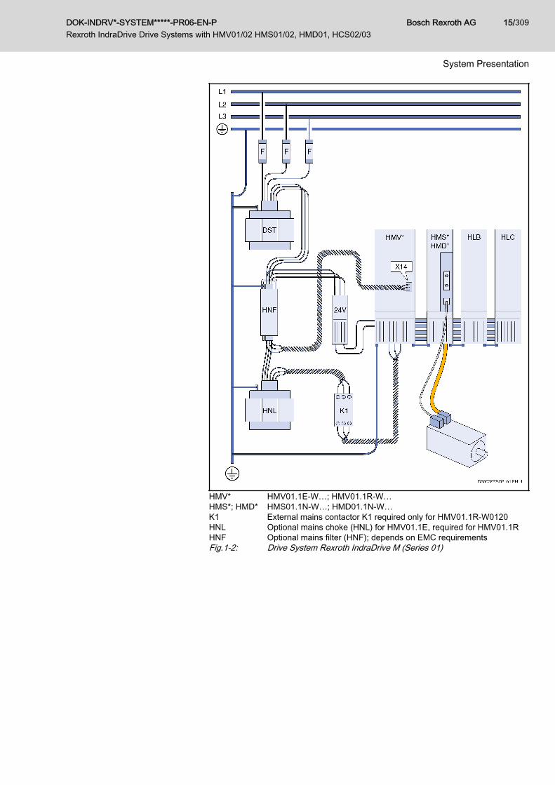
HMV* HMV01.1E-W…; HMV01.1R-W…HMS*; HMD* HMS01.1N-W…; HMD01.1N-W…K1 External mains contactor K1 required only for HMV01.1R-W0120HNL Optional mains choke (HNL) for HMV01.1E, required for HMV01.1RHNF Optional mains filter (HNF); depends on EMC requirementsFig.1-2: Drive System Rexroth IndraDrive M (Series 01)
DOK-INDRV*-SYSTEM*****-PR06-EN-P Rexroth IndraDrive Drive Systems with HMV01/02 HMS01/02, HMD01, HCS02/03
Bosch Rexroth AG 15/309
System Presentation

HMV02* HMV02.1R-W…HMS02* HMS02.1N-W…HLB* HLB01.1C (optional)HLC* HLC01.1C (optional)Fig.1-3: Drive System Rexroth IndraDrive M (Series 02)
Bosch Rexroth AG DOK-INDRV*-SYSTEM*****-PR06-EN-P Rexroth IndraDrive Drive Systems with HMV01/02 HMS01/02, HMD01, HCS02/03
16/309
System Presentation
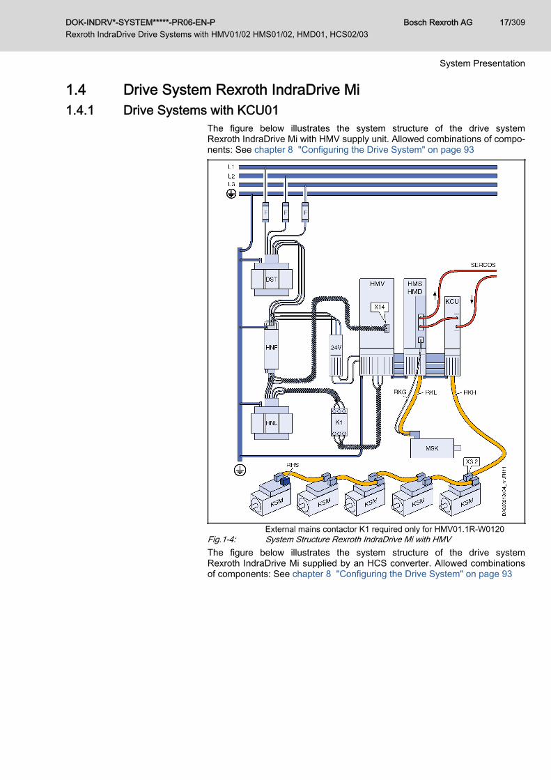
1.4 Drive System Rexroth IndraDrive Mi1.4.1 Drive Systems with KCU01
The figure below illustrates the system structure of the drive systemRexroth IndraDrive Mi with HMV supply unit. Allowed combinations of compo‐nents: See chapter 8 "Configuring the Drive System" on page 93
External mains contactor K1 required only for HMV01.1R-W0120Fig.1-4: System Structure Rexroth IndraDrive Mi with HMVThe figure below illustrates the system structure of the drive systemRexroth IndraDrive Mi supplied by an HCS converter. Allowed combinationsof components: See chapter 8 "Configuring the Drive System" on page 93
DOK-INDRV*-SYSTEM*****-PR06-EN-P Rexroth IndraDrive Drive Systems with HMV01/02 HMS01/02, HMD01, HCS02/03
Bosch Rexroth AG 17/309
System Presentation
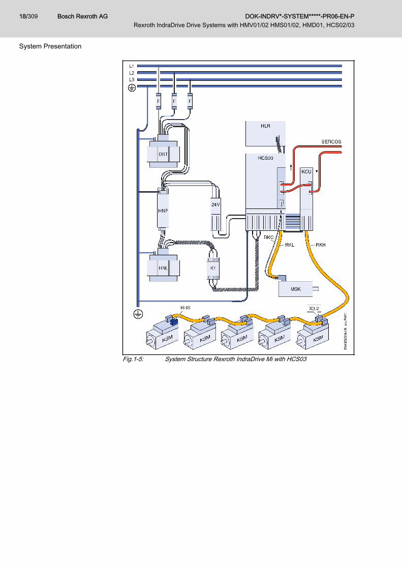
Fig.1-5: System Structure Rexroth IndraDrive Mi with HCS03
Bosch Rexroth AG DOK-INDRV*-SYSTEM*****-PR06-EN-P Rexroth IndraDrive Drive Systems with HMV01/02 HMS01/02, HMD01, HCS02/03
18/309
System Presentation
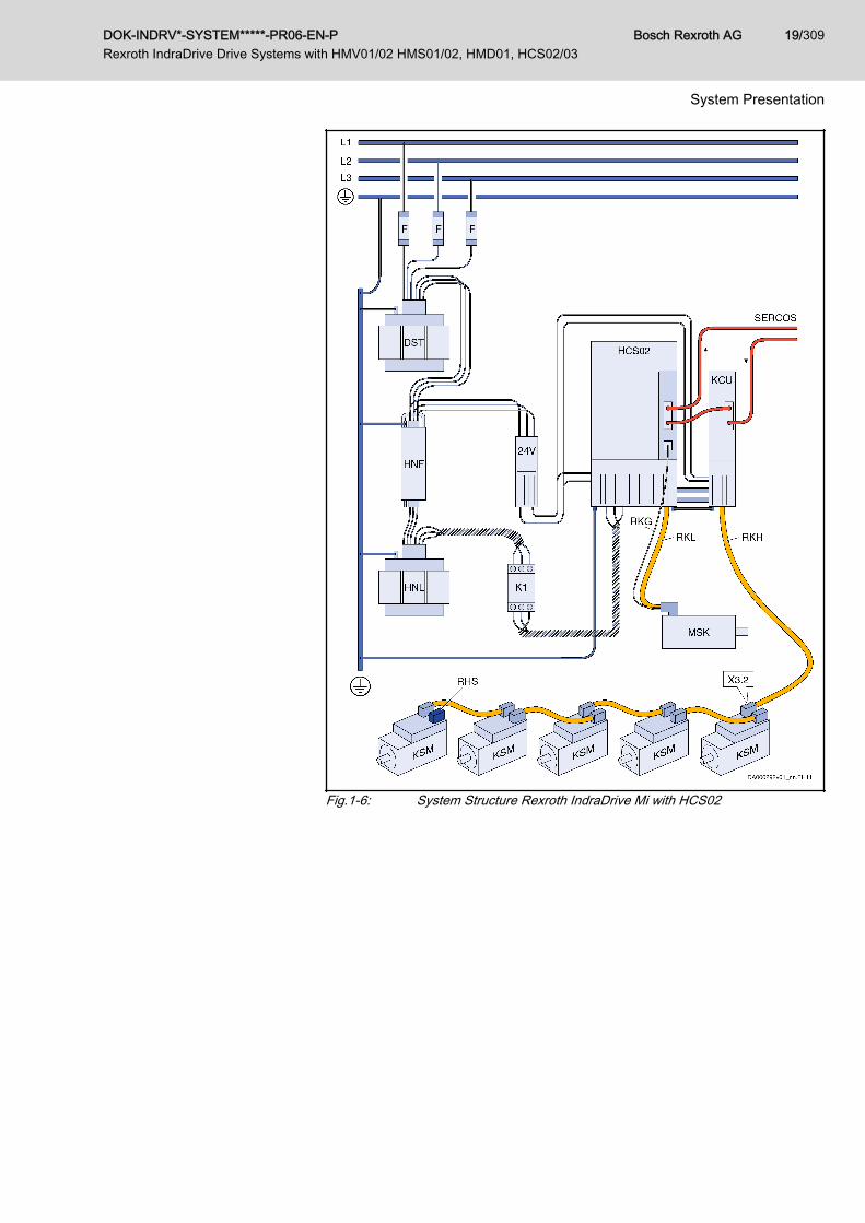
Fig.1-6: System Structure Rexroth IndraDrive Mi with HCS02
DOK-INDRV*-SYSTEM*****-PR06-EN-P Rexroth IndraDrive Drive Systems with HMV01/02 HMS01/02, HMD01, HCS02/03
Bosch Rexroth AG 19/309
System Presentation
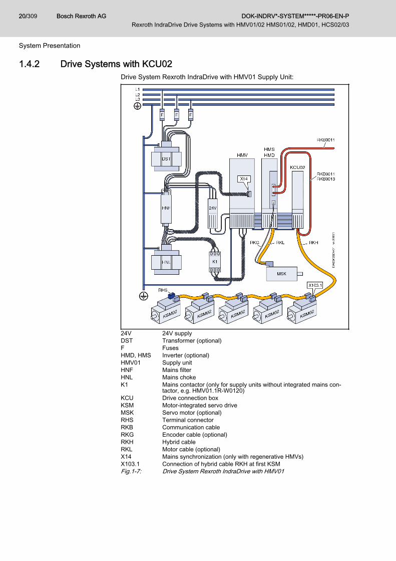
1.4.2 Drive Systems with KCU02Drive System Rexroth IndraDrive with HMV01 Supply Unit:
24V 24V supplyDST Transformer (optional)F FusesHMD, HMS Inverter (optional)HMV01 Supply unitHNF Mains filterHNL Mains chokeK1 Mains contactor (only for supply units without integrated mains con‐
tactor, e.g. HMV01.1R-W0120)KCU Drive connection boxKSM Motor-integrated servo driveMSK Servo motor (optional)RHS Terminal connectorRKB Communication cableRKG Encoder cable (optional)RKH Hybrid cableRKL Motor cable (optional)X14 Mains synchronization (only with regenerative HMVs)X103.1 Connection of hybrid cable RKH at first KSMFig.1-7: Drive System Rexroth IndraDrive with HMV01
Bosch Rexroth AG DOK-INDRV*-SYSTEM*****-PR06-EN-P Rexroth IndraDrive Drive Systems with HMV01/02 HMS01/02, HMD01, HCS02/03
20/309
System Presentation

Drive System Rexroth IndraDrive with HCS02 Supply Unit:
DST Transformer (optional)F FusesHCS02 Converter (HCS02.1E-W0054 or HCS02.1E-W0070)HNF Mains filterHNL Mains choke (optional)HLC01 DC bus capacitor unit (optional only with low load of motor output at
HCS02)K1 Mains contactorKCU Drive connection boxKSM Motor-integrated servo driveMSK Servo motor24V 24V supplyRHS Terminal connectorRKB Communication cableRKG Encoder cableRKH Hybrid cableRKL Motor cableX103.1 Connection of hybrid cable at first KSMFig.1-8: Drive System Rexroth IndraDrive with HCS02
DOK-INDRV*-SYSTEM*****-PR06-EN-P Rexroth IndraDrive Drive Systems with HMV01/02 HMS01/02, HMD01, HCS02/03
Bosch Rexroth AG 21/309
System Presentation

Drive System Rexroth IndraDrive with HCS03 Supply Unit:
DST Transformer (optional)F FusesHCS03 ConverterHLR Braking resistor (optional)HNF Mains filterHNL Mains choke (optional)K1 Mains contactorKCU Drive connection boxKSM Motor-integrated servo driveMSK Servo motorRHS Terminal connectorRKB Communication cableRKH Hybrid cableRKG Encoder cableRKL Motor cable24V 24V supplyX103.1 Connection of hybrid cable at first KSMFig.1-9: Drive System Rexroth IndraDrive with HCS03
Bosch Rexroth AG DOK-INDRV*-SYSTEM*****-PR06-EN-P Rexroth IndraDrive Drive Systems with HMV01/02 HMS01/02, HMD01, HCS02/03
22/309
System Presentation
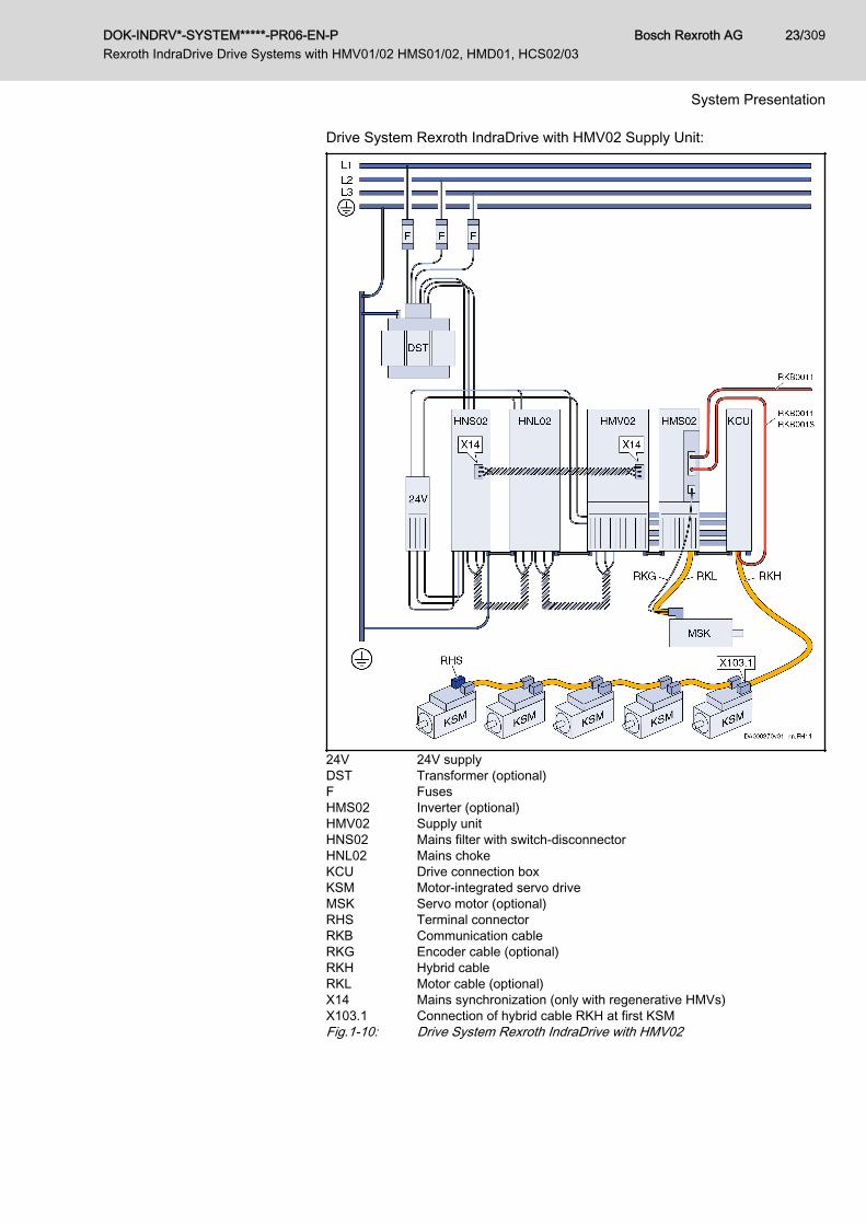
Drive System Rexroth IndraDrive with HMV02 Supply Unit:
24V 24V supplyDST Transformer (optional)F FusesHMS02 Inverter (optional)HMV02 Supply unitHNS02 Mains filter with switch-disconnectorHNL02 Mains chokeKCU Drive connection boxKSM Motor-integrated servo driveMSK Servo motor (optional)RHS Terminal connectorRKB Communication cableRKG Encoder cable (optional)RKH Hybrid cableRKL Motor cable (optional)X14 Mains synchronization (only with regenerative HMVs)X103.1 Connection of hybrid cable RKH at first KSMFig.1-10: Drive System Rexroth IndraDrive with HMV02
DOK-INDRV*-SYSTEM*****-PR06-EN-P Rexroth IndraDrive Drive Systems with HMV01/02 HMS01/02, HMD01, HCS02/03
Bosch Rexroth AG 23/309
System Presentation

1.5 Combinations of Rexroth IndraDrive C withRexroth IndraDrive M and Rexroth IndraDrive Mi
On the common Rexroth IndraDrive platform, it is possible to combine thecomponents of the product ranges Rexroth IndraDrive C, RexrothIndraDrive M and Rexroth IndraDrive Mi to form drive systems of optimumcosts and performance.To supply the components of the product range Rexroth IndraDrive Mi (KCUwith KSM/KMS), you can use:● Modular HMV01 and HMV02 supply units● HCS02 and HCS03 convertersAllowed combinations of components: See chapter 8 "Configuring the DriveSystem" on page 93
1.6 Basic Design of the Devices1.6.1 General Information
1 Power section2 Control sectionFig.1-11: Basic Design of a Drive ControllerA drive controller consists of two essential parts:● Power section● Control section
1.6.2 Power SectionThe power section incorporates the control section and has the following con‐nections:● Mains voltage connection (at HCS devices)
Bosch Rexroth AG DOK-INDRV*-SYSTEM*****-PR06-EN-P Rexroth IndraDrive Drive Systems with HMV01/02 HMS01/02, HMD01, HCS02/03
24/309
System Presentation

● Motor connection (with optional motor holding brake and motor tempera‐ture monitor)
● 24 V control voltage● DC bus connection● Module bus connection for cross communication in the case of DC bus
connection with other devices● Connection for external braking resistor (at HCS devices)
For detailed information on the power sections, see Project PlanningManual "Rexroth IndraDrive Supply Units and Power Sections".
1.6.3 Control SectionThe control section is a separate component which is plugged into the powersection. The control section consists of:● Basic control section circuit board with interfaces● Optional modules (only for configurable control sections)The drive controller is supplied complete with factory-installed (possibly con‐figured) control section.
Only especially trained staff are allowed to replace control sec‐tions.
For detailed information on the control sections, see Project PlanningManual "Rexroth IndraDrive Drive Controllers Control Sections".
DOK-INDRV*-SYSTEM*****-PR06-EN-P Rexroth IndraDrive Drive Systems with HMV01/02 HMS01/02, HMD01, HCS02/03
Bosch Rexroth AG 25/309
System Presentation

1.7 Overview of Type Currents and Type Performances1.7.1 General Information
To allow you selecting appropriate drive controllers for a multitude of applica‐tions, the Rexroth IndraDrive product range includes a wide range of typecurrents and performances. The table below shows the fundamental data ofdrive controllers and supply units.
For detailed technical data, see Project Planning Manual "RexrothIndraDrive Supply Units and Power Sections".
1.7.2 Drive ControllersThe order of the following table lines conforms with the peak currents of thedevices.
Compact converters Modular inverters Type current Contin. currentIout_cont_4k [A] 1)
Peak currentIout_max_4k [A] 1)
Nominal motorpower [kW] 2)
HCS01 - W00033) 3
HCS01 - W00054) 5
HCS01 - W00063) 6
HCS01 - W00084) 8
HCS01 - W00093) 9
HCS02 - W0012 4 12 1,5
- HMD01 W0012 6,9 12 -
HCS01 - W00133) 13
HCS01 - W00184) 18
- HMS01 W0020 12,1 20 -
- HMD01 W0020 12,1 20 -
HCS01 - W00284) 28
HCS02 - W0028 11 28 4,0
- HMS02 W0028 13 28 -
- HMS01 W0036 21,3 36 -
- HMD01 W0036 20 36 -
HCS02 - W0054 22 54 7,5
- HMS01 W0054 35 54 -
- HMS02 W0054 25 54 -
HCS02 - W0070 28 70 11
HCS03 - W0070 45 70 18,5
- HMS01 W0070 42,4 70 -
HCS03 - W0100 73 100 30
- HMS01 W0110 68,5 110 -
HCS03 - W0150 95 150 45
Bosch Rexroth AG DOK-INDRV*-SYSTEM*****-PR06-EN-P Rexroth IndraDrive Drive Systems with HMV01/02 HMS01/02, HMD01, HCS02/03
26/309
System Presentation
Compact converters Modular inverters Type current Contin. currentIout_cont_4k [A] 1)
Peak currentIout_max_4k [A] 1)
Nominal motorpower [kW] 2)
- HMS01 W0150 100 150 -
HCS03 - W0210 145 210 75
- HMS01 W0210 145 210 -
- HMS01 W0350 250 350 -
1) At fs = 4 kHz; without overload2) For standard motor 3 AC 400 V; use of mains choke HNL01; variable
torque3) Mains connection voltage 3 AC 110 ... 230 V4) Mains connection voltage 3 AC 200 ... 500 VTab.1-4: Type Current and Type Performances
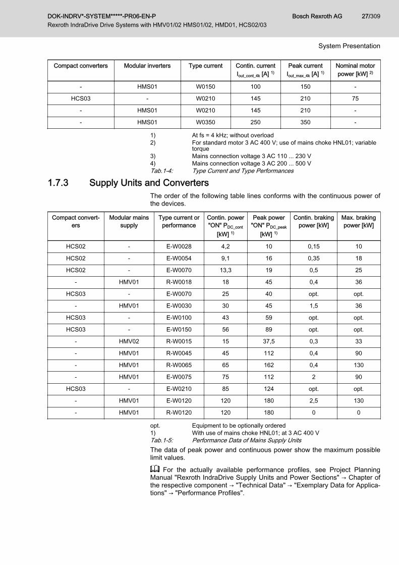
1.7.3 Supply Units and ConvertersThe order of the following table lines conforms with the continuous power ofthe devices.
Compact convert‐ers
Modular mainssupply
Type current orperformance
Contin. power"ON" PDC_cont
[kW] 1)
Peak power"ON" PDC_peak
[kW] 1)
Contin. brakingpower [kW]
Max. brakingpower [kW]
HCS02 - E-W0028 4,2 10 0,15 10
HCS02 - E-W0054 9,1 16 0,35 18
HCS02 - E-W0070 13,3 19 0,5 25
- HMV01 R-W0018 18 45 0,4 36
HCS03 - E-W0070 25 40 opt. opt.
- HMV01 E-W0030 30 45 1,5 36
HCS03 - E-W0100 43 59 opt. opt.
HCS03 - E-W0150 56 89 opt. opt.
- HMV02 R-W0015 15 37,5 0,3 33
- HMV01 R-W0045 45 112 0,4 90
- HMV01 R-W0065 65 162 0,4 130
- HMV01 E-W0075 75 112 2 90
HCS03 - E-W0210 85 124 opt. opt.
- HMV01 E-W0120 120 180 2,5 130
- HMV01 R-W0120 120 180 0 0
opt. Equipment to be optionally ordered1) With use of mains choke HNL01; at 3 AC 400 VTab.1-5: Performance Data of Mains Supply UnitsThe data of peak power and continuous power show the maximum possiblelimit values.
For the actually available performance profiles, see Project PlanningManual "Rexroth IndraDrive Supply Units and Power Sections" → Chapter ofthe respective component → "Technical Data" → "Exemplary Data for Applica‐tions" → "Performance Profiles".
DOK-INDRV*-SYSTEM*****-PR06-EN-P Rexroth IndraDrive Drive Systems with HMV01/02 HMS01/02, HMD01, HCS02/03
Bosch Rexroth AG 27/309
System Presentation

1.8 Overview of Functions1.8.1 Supply Units and Power Sections
For an overview of the functions of supply units and power sections, seeProject Planning Manual "Rexroth IndraDrive Supply Units and Power Sec‐tions" → "Functions and Connection Points" → "Overview of Functions, PowerSections and Supply Units".
1.8.2 Control Sections For an overview of the functions of control sections, see Project Planning
Manual "Rexroth IndraDrive Drive Controllers Control Sections" → "RexrothIndraDrive Control Sections" → "Overview of Functions and Interfaces of theControl Sections".
1.9 Documentations1.9.1 About This Documentation
Personal injury and property damage causedby incorrect project planning for applications,machines and installations!
WARNING
Observe the contents of the documentations relevant to your drive system.
Purpose of Documentation This documentation contains● Overview information of the Rexroth IndraDrive drive system● Description of the allowed combinations of Rexroth IndraDrive system
components● Selection of the system components of the Rexroth IndraDrive drive
system● Specification applying to all components (ambient and operating condi‐
tions)● Application description of system characteristics
Changes in Comparison to Previ‐ous Edition Chapter Changes
All chapters Design of safety instructions modified in accordance withthe ANSI Z535.6 standard
System Presentation Drive systems IndraDrive Mi with KCU02, KSM02 andKMS02 includedOverview of documentations updated
Brief Description, Us‐age
KCU, KSM, KMS components includedCSE02, CSB02, CDB02, CSH02 control sections included
Bosch Rexroth AG DOK-INDRV*-SYSTEM*****-PR06-EN-P Rexroth IndraDrive Drive Systems with HMV01/02 HMS01/02, HMD01, HCS02/03
28/309
System Presentation

Chapter Changes
General Data andSpecifications
Standards updatedUL file numbers includedAmbient and Operating Conditions: One table each cre‐ated for Rexroth IndraDrive and Rexroth IndraDrive Mi anddata updatedDescription of mounting positions revisedChapter "Prime Coat and Housing Varnish" renamed as"Motor Varnish" and updated
Project Planning ofMains Connection
IT mains type: HCS03 not allowedChapter "Protective Grounding": Note on fault loop impe‐dance and disconnecting time of mains circuit breaker in‐cluded
Configuration of theDrive System
Mains Connection for HCS Converters - Additional Com‐ponents: Table "Cy, Capacitances against Housing" re‐visedKCU02, KSM02 and KMS02 includedSupply units of "FNN2" design (Smart Energy Mode) inclu‐ded
Circuits for the MainsConnection
HMV01.1R with HLB01.1D included
Arranging the Compo‐nents in the ControlCabinet
Chapter "EMC-Optimal Installation in Facility and ControlCabinet" revised
Project Planning ofCooling System
Contents revised
Environmental Protec‐tion and Disposal
Information on batteries and accumulators included
Service and Support Contents updated
Appendix Discharging of Capacitors: Discharging device removed
Tab.1-6: Changes
1.9.2 Overview of DocumentationsDrive Systems, System ComponentsTitleRexroth IndraDrive …
Kind of documentation Document typecode1)
DOK-INDRV*-…
Material numberR911…
Drive Systems with HMV01/02HMS01/02, HMD01, HCS02/03
Project Planning Manual SYSTEM*****-PRxx-EN-P 309636
Mi Drive Systemswith KCU01, KSM01, KMS01
Project Planning Manual KCU+KSM****-PRxx-EN-P 320924
Mi Drive Systemswith KCU02, KSM02, KMS02
Project Planning Manual KCU02+KSM02-PRxx-EN-P 335703
DOK-INDRV*-SYSTEM*****-PR06-EN-P Rexroth IndraDrive Drive Systems with HMV01/02 HMS01/02, HMD01, HCS02/03
Bosch Rexroth AG 29/309
System Presentation

TitleRexroth IndraDrive …
Kind of documentation Document typecode1)
DOK-INDRV*-…
Material numberR911…
Supply Units, Power SectionsHMV, HMS, HMD, HCS02, HCS03
Project Planning Manual HMV-S-D+HCS-PRxx-EN-P 318790
Drive ControllersControl Sections CSB01, CSH01,CDB01
Project Planning Manual CSH********-PRxx-EN-P 295012
Control SectionsCSE02, CSB02, CDB02, CSH02
Project Planning Manual Cxx02******-PRxx-EN-P 338962
Additional Components and Accesso‐ries
Project Planning Manual ADDCOMP****-PRxx-EN-P 306140
1) In the document typecodes, "xx" is a wild card for the current edition ofthe documentation (example: PR01 is the first edition of a ProjectPlanning Manual)
Tab.1-7: Documentations – Overview
Title Kind of documentation Document typecode1) Material numberR911…
Automation TerminalsOf The Rexroth InlineProduct Range
Application Manual DOK-CONTRL-ILSYSINS***-AWxx-EN-P
317021
1) In the document typecodes, "xx" is a wild card for the current edition ofthe documentation (example: AW01 is the first edition of an Applica‐tion Manual)
Tab.1-8: Documentations – Overview
MotorsTitleRexroth IndraDyn …
Kind of documentation Document typecode1)
DOK-MOTOR*-…
Material numberR911…
A Asynchronous Motors MAD / MAF Project Planning Manual MAD/MAF****-PRxx-EN-P 295781
H Synchronous Kit Spindle Motors Project Planning Manual MBS-H******-PRxx-EN-P 297895
L Synchronous Linear Motors Project Planning Manual MLF********-PRxx-EN-P 293635
S Synchronous Motors MSK Project Planning Manual MSK********-PRxx-EN-P 296289
T Synchronous Torque Motors Project Planning Manual MBT********-PRxx-EN-P 298798
1) In the document typecodes, "xx" is a wild card for the current edition ofthe documentation (example: PR01 is the first edition of a ProjectPlanning Manual)
Tab.1-9: Documentations – Overview
Bosch Rexroth AG DOK-INDRV*-SYSTEM*****-PR06-EN-P Rexroth IndraDrive Drive Systems with HMV01/02 HMS01/02, HMD01, HCS02/03
30/309
System Presentation

CablesTitle Kind of documentation Document typecode1)
DOK-…
Material numberR911…
Rexroth Connection CablesIndraDrive and IndraDyn
Selection Data CONNEC-CABLE*INDRV-CAxx-EN-P
322949
1) In the document typecodes, "xx" is a wild card for the current edition ofthe documentation (example: CA02 is the second edition of the docu‐mentation "Selection Data")
Tab.1-10: Documentations – Overview
FirmwareTitleRexroth IndraDrive …
Kind of documentation Document typecode1)
DOK-INDRV*-…
Part numberR911…
Firmware for Drive ControllersMPH-08, MPB-08, MPD-08, MPC-08
Functional Description MP*-08VRS**-APxx-EN-P 332643
Firmware for Drive ControllersMPH-07, MPB-07, MPD-07, MPC-07
Functional Description MP*-07VRS**-FKxx-EN-P 328670
Firmware for Drive ControllersMPH-06, MPB-06, MPD-06, MPC-06
Functional Description MP*-06VRS**-FKxx-EN-P 326766
Firmware for Drive ControllersMPH-05, MPB-05, MPD-05
Functional Description MP*-05VRS**-FKxx-EN-P 320182
Firmware for Drive ControllersMPH-04, MPB-04, MPD-04
Functional Description MP*-04VRS**-FKxx-EN-P 315485
Firmware for Drive ControllersMPH-03, MPB-03, MPD-03
Functional Description MP*-03VRS**-FKxx-EN-P 308329
Firmware for Drive ControllersMPH-02, MPB-02, MPD-02
Functional Description MP*-02VRS**-FKxx-EN-P 299223
Drive ControllersMPx-02 to MPx-08
Parameter Description GEN-**VRS**-PAxx-EN-P 297317
MPx-02 to MPx-08and HMV
Troubleshooting Guide GEN-**VRS**-WAxx-EN-P 297319
Integrated Safety Technology Functional and ApplicationDescription
SI*-**VRS**-FKxx-EN-P 297838
Integrated Safety TechnologyAccording to IEC61508
Functional Description SI2-**VRS**-FKxx-EN-P 327664
Rexroth IndraMotion MLD Application Manual MLD-**VRS**-AWxx-EN-P 306084
Rexroth IndraMotion MLDLibrary
Library Description MLD-SYSLIB*-FKxx-EN-P 309224
1) In the document typecodes, "xx" is a wild card for the current edition ofthe documentation (example: FK02 is the second edition of a Func‐tional Description)
Tab.1-11: Documentations – Overview
DOK-INDRV*-SYSTEM*****-PR06-EN-P Rexroth IndraDrive Drive Systems with HMV01/02 HMS01/02, HMD01, HCS02/03
Bosch Rexroth AG 31/309
System Presentation
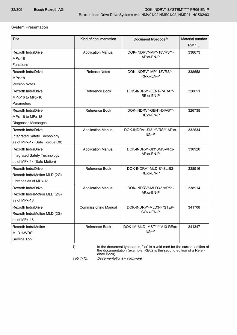
Title Kind of documentation Document typecode1) Material numberR911…
Rexroth IndraDriveMPx-18Functions
Application Manual DOK-INDRV*-MP*-18VRS**-APxx-EN-P
338673
Rexroth IndraDriveMPx-18Version Notes
Release Notes DOK-INDRV*-MP*-18VRS**-RNxx-EN-P
338658
Rexroth IndraDriveMPx-16 to MPx-18Parameters
Reference Book DOK-INDRV*-GEN1-PARA**-RExx-EN-P
328651
Rexroth IndraDriveMPx-16 to MPx-18Diagnostic Messages
Reference Book DOK-INDRV*-GEN1-DIAG**-RExx-EN-P
326738
Rexroth IndraDriveIntegrated Safety Technologyas of MPx-1x (Safe Torque Off)
Application Manual DOK-INDRV*-SI3-**VRS**-APxx-EN-P
332634
Rexroth IndraDriveIntegrated Safety Technologyas of MPx-1x (Safe Motion)
Application Manual DOK-INDRV*-SI3*SMO-VRS-APxx-EN-P
338920
Rexroth IndraDriveRexroth IndraMotion MLD (2G)Libraries as of MPx-18
Reference Book DOK-INDRV*-MLD-SYSLIB3-RExx-EN-P
338916
Rexroth IndraDriveRexroth IndraMotion MLD (2G)as of MPx-18
Application Manual DOK-INDRV*-MLD3-**VRS*-APxx-EN-P
338914
Rexroth IndraDriveRexroth IndraMotion MLD (2G)as of MPx-18
Commissioning Manual DOK-INDRV*-MLD3-F*STEP-COxx-EN-P
341708
Rexroth IndraMotionMLD 13VRSService Tool
Reference Book DOK-IM*MLD-IMST****V13-RExx-EN-P
341347
1) In the document typecodes, "xx" is a wild card for the current edition ofthe documentation (example: RE02 is the second edition of a Refer‐ence Book)
Tab.1-12: Documentations – Firmware
Bosch Rexroth AG DOK-INDRV*-SYSTEM*****-PR06-EN-P Rexroth IndraDrive Drive Systems with HMV01/02 HMS01/02, HMD01, HCS02/03
32/309
System Presentation

Title Kind of documentation Document typecode1) Material numberR911…
Productivity AgentExtended Diagnostic Functions withRexroth IndraDrive
Application Manual DOK-INDRV*-MLD-PAGENT*-AWxx-EN-P
323947
1) In the document typecodes, "xx" is a wild card for the current edition ofthe documentation (example: AW01 is the first edition of an Applica‐tion Manual)
Tab.1-13: Documentations – Overview
DOK-INDRV*-SYSTEM*****-PR06-EN-P Rexroth IndraDrive Drive Systems with HMV01/02 HMS01/02, HMD01, HCS02/03
Bosch Rexroth AG 33/309
System Presentation

1.9.3 Your Feedback
Your experience is important for our improvement processes ofproducts and documentations.
Inform us about mistakes you discovered in this documentation and changesyou suggest; we would be grateful for your feedback.Please send your remarks to:
Address for Your Feedback Bosch Rexroth AGDept. DC-IA/EDY1Buergermeister-Dr.-Nebel-Str. 297816 Lohr, GermanyE-mail: [email protected]
Bosch Rexroth AG DOK-INDRV*-SYSTEM*****-PR06-EN-P Rexroth IndraDrive Drive Systems with HMV01/02 HMS01/02, HMD01, HCS02/03
34/309
System Presentation
2 Important Directions for Use2.1 Appropriate Use2.1.1 Introduction
Rexroth products reflect the state-of-the-art in their development and theirmanufacture. They are tested prior to delivery to ensure operating safety andreliability.
Personal injury and property damage causedby incorrect use of the products!
WARNING
The products have been designed for use in industrial environments and mayonly be used in the appropriate way. If they are not used in the appropriateway, situations resulting in property damage and personal injury can occur.
Rexroth as manufacturer is not liable for any damages resultingfrom inappropriate use. In such cases, the guarantee and theright to payment of damages resulting from inappropriate use areforfeited. The user alone carries all responsibility of the risks.
Before using Rexroth products, the following pre-requisites must be met toensure appropriate use of the products:● Personnel that in any way, shape or form uses our products must first
read and understand the relevant safety instructions and be familiar withtheir appropriate use.
● If the products take the form of hardware, then they must remain in theiroriginal state, in other words, no structural changes are permitted. It isnot permitted to decompile software products or alter source codes.
● Damaged or faulty products may not be installed or put into operation.● Make sure that the products have been installed in the manner descri‐
bed in the relevant documentation.
2.1.2 Areas of Use and ApplicationDrive controllers made by Rexroth are designed to control electrical motorsand monitor their operation.Control and monitoring of the Drive controllers may require additional sensorsand actors.
The drive controllers may only be used with the accessories andparts specified in this documentation. If a component has notbeen specifically named, then it may neither be mounted nor con‐nected. The same applies to cables and lines.Operation is only permitted in the specified configurations andcombinations of components using the software and firmware asspecified in the relevant Functional Descriptions.
Drive controllers have to be programmed before commissioning to ensurethat the motor executes the specific functions of an application.Drive controllers of the Rexroth IndraDrive line have been developed for usein single- and multi-axis drive and control tasks.
DOK-INDRV*-SYSTEM*****-PR06-EN-P Rexroth IndraDrive Drive Systems with HMV01/02 HMS01/02, HMD01, HCS02/03
Bosch Rexroth AG 35/309
Important Directions for Use

To ensure application-specific use of Drive controllers, device types of differ‐ent drive power and different interfaces are available.Typical applications include, for example:● Handling and mounting systems,● Packaging and food machines,● Printing and paper processing machines and● Machine tools.Drive controllers may only be operated under the assembly and installationconditions described in this documentation, in the specified position of normaluse and under the ambient conditions as described (temperature, degree ofprotection, humidity, EMC, etc.).
2.2 Inappropriate UseUsing the Drive controllers outside of the operating conditions described inthis documentation and outside of the technical data and specifications givenis defined as "inappropriate use".Drive controllers may not be used, if ...● they are subject to operating conditions that do not meet the specified
ambient conditions. This includes, for example, operation under water,under extreme temperature fluctuations or extremely high maximumtemperatures.
● Furthermore, Drive controllers may not be used in applications whichhave not been expressly authorized by Rexroth. Please carefully followthe specifications outlined in the general Safety Instructions!
Components of the Rexroth IndraDrive system are products ofcategory C3 (with limited availability) according to IEC 61800‑3.To ensure that this category (limit values) is maintained, suitableline filters must be used in the drive system.These components are not provided for use in a public low-volt‐age network supplying residential areas with power. If these com‐ponents are used in such a public network, high-frequency inter‐ference is to be expected. This can require additional measuresof radio interference suppression.
Bosch Rexroth AG DOK-INDRV*-SYSTEM*****-PR06-EN-P Rexroth IndraDrive Drive Systems with HMV01/02 HMS01/02, HMD01, HCS02/03
36/309
Important Directions for Use

3 Safety Instructions for Electric Drives and Controls3.1 Definitions of Terms
Application Documentation Application documentation comprises the entire documentation used to in‐form the user of the product about the use and safety-relevant features forconfiguring, integrating, installing, mounting, commissioning, operating, main‐taining, repairing and decommissioning the product. The following terms arealso used for this kind of documentation: Operating Instructions, Commis‐sioning Manual, Instruction Manual, Project Planning Manual, Application De‐scription, etc.
Component A component is a combination of elements with a specified function, whichare part of a piece of equipment, device or system. Components of the elec‐tric drive and control system are, for example, supply units, drive controllers,mains choke, mains filter, motors, cables, etc.
Control System A control system comprises several interconnected control componentsplaced on the market as a single functional unit.
Device A device is a finished product with a defined function, intended for users andplaced on the market as an individual piece of merchandise.
Electrical Equipment Electrical equipment encompasses all devices used to generate, convert,transmit, distribute or apply electrical energy, such as electric motors, trans‐formers, switching devices, cables, lines, power-consuming devices, circuitboard assemblies, plug-in units, control cabinets, etc.
Electric Drive System An electric drive system comprises all components from mains supply to mo‐tor shaft; this includes, for example, electric motor(s), motor encoder(s), sup‐ply units and drive controllers, as well as auxiliary and additional compo‐nents, such as mains filter, mains choke and the corresponding lines and ca‐bles.
Installation An installation consists of several devices or systems interconnected for adefined purpose and on a defined site which, however, are not intended to beplaced on the market as a single functional unit.
Machine A machine is the entirety of interconnected parts or units at least one ofwhich is movable. Thus, a machine consists of the appropriate machine driveelements, as well as control and power circuits, which have been assembledfor a specific application. A machine is, for example, intended for processing,treatment, movement or packaging of a material. The term "machine" alsocovers a combination of machines which are arranged and controlled in sucha way that they function as a unified whole.
Manufacturer The manufacturer is an individual or legal entity bearing responsibility for thedesign and manufacture of a product which is placed on the market in the in‐dividual's or legal entity's name. The manufacturer can use finished products,finished parts or finished elements, or contract out work to subcontractors.However, the manufacturer must always have overall control and possessthe required authority to take responsibility for the product.
Product Examples of a product: Device, component, part, system, software, firmware,among other things.
Project Planning Manual A project planning manual is part of the application documentation used tosupport the sizing and planning of systems, machines or installations.
Qualified Persons In terms of this application documentation, qualified persons are those per‐sons who are familiar with the installation, mounting, commissioning and op‐eration of the components of the electric drive and control system, as well aswith the hazards this implies, and who possess the qualifications their work
DOK-INDRV*-SYSTEM*****-PR06-EN-P Rexroth IndraDrive Drive Systems with HMV01/02 HMS01/02, HMD01, HCS02/03
Bosch Rexroth AG 37/309
Safety Instructions for Electric Drives and Controls
requires. To comply with these qualifications, it is necessary, among otherthings,1) to be trained, instructed or authorized to switch electric circuits and devi‐ces safely on and off, to ground them and to mark them2) to be trained or instructed to maintain and use adequate safety equipment3) to attend a course of instruction in first aid
User A user is a person installing, commissioning or using a product which hasbeen placed on the market.
3.2 General Information3.2.1 Using the Safety Instructions and Passing Them on to Others
Do not attempt to install and operate the components of the electric drive andcontrol system without first reading all documentation provided with the prod‐uct. Read and understand these safety instructions and all user documenta‐tion prior to working with these components. If you do not have the user doc‐umentation for the components, contact your responsible Rexroth sales part‐ner. Ask for these documents to be sent immediately to the person or per‐sons responsible for the safe operation of the components.If the component is resold, rented and/or passed on to others in any otherform, these safety instructions must be delivered with the component in theofficial language of the user's country.Improper use of these components, failure to follow the safety instructions inthis document or tampering with the product, including disabling of safety de‐vices, could result in property damage, injury, electric shock or even death.
3.2.2 Requirements for Safe UseRead the following instructions before initial commissioning of the compo‐nents of the electric drive and control system in order to eliminate the risk ofinjury and/or property damage. You must follow these safety instructions.● Rexroth is not liable for damages resulting from failure to observe the
safety instructions.● Read the operating, maintenance and safety instructions in your lan‐
guage before commissioning. If you find that you cannot completely un‐derstand the application documentation in the available language,please ask your supplier to clarify.
● Proper and correct transport, storage, mounting and installation, as wellas care in operation and maintenance, are prerequisites for optimal andsafe operation of the component.
● Only qualified persons may work with components of the electric driveand control system or within its proximity.
● Only use accessories and spare parts approved by Rexroth.● Follow the safety regulations and requirements of the country in which
the components of the electric drive and control system are operated.● Only use the components of the electric drive and control system in the
manner that is defined as appropriate. See chapter "Appropriate Use".● The ambient and operating conditions given in the available application
documentation must be observed.● Applications for functional safety are only allowed if clearly and explicitly
specified in the application documentation "Integrated Safety Technolo‐
Bosch Rexroth AG DOK-INDRV*-SYSTEM*****-PR06-EN-P Rexroth IndraDrive Drive Systems with HMV01/02 HMS01/02, HMD01, HCS02/03
38/309
Safety Instructions for Electric Drives and Controls
gy". If this is not the case, they are excluded. Functional safety is a safe‐ty concept in which measures of risk reduction for personal safety de‐pend on electrical, electronic or programmable control systems.
● The information given in the application documentation with regard tothe use of the delivered components contains only examples of applica‐tions and suggestions.The machine and installation manufacturers must– make sure that the delivered components are suited for their indi‐
vidual application and check the information given in this applica‐tion documentation with regard to the use of the components,
– make sure that their individual application complies with the appli‐cable safety regulations and standards and carry out the requiredmeasures, modifications and complements.
● Commissioning of the delivered components is only allowed once it issure that the machine or installation in which the components are instal‐led complies with the national regulations, safety specifications andstandards of the application.
● Operation is only allowed if the national EMC regulations for the applica‐tion are met.
● The instructions for installation in accordance with EMC requirementscan be found in the section on EMC in the respective application docu‐mentation.The machine or installation manufacturer is responsible for compliancewith the limit values as prescribed in the national regulations.
● The technical data, connection and installation conditions of the compo‐nents are specified in the respective application documentations andmust be followed at all times.
National regulations which the user must take into account● European countries: In accordance with European EN standards● United States of America (USA):
– National Electrical Code (NEC)– National Electrical Manufacturers Association (NEMA), as well as
local engineering regulations– Regulations of the National Fire Protection Association (NFPA)
● Canada: Canadian Standards Association (CSA)● Other countries:
– International Organization for Standardization (ISO)– International Electrotechnical Commission (IEC)
3.2.3 Hazards by Improper Use● High electrical voltage and high working current! Danger to life or seri‐
ous injury by electric shock!● High electrical voltage by incorrect connection! Danger to life or injury by
electric shock!● Dangerous movements! Danger to life, serious injury or property dam‐
age by unintended motor movements!● Health hazard for persons with heart pacemakers, metal implants and
hearing aids in proximity to electric drive systems!
DOK-INDRV*-SYSTEM*****-PR06-EN-P Rexroth IndraDrive Drive Systems with HMV01/02 HMS01/02, HMD01, HCS02/03
Bosch Rexroth AG 39/309
Safety Instructions for Electric Drives and Controls

● Risk of burns by hot housing surfaces!● Risk of injury by improper handling! Injury by crushing, shearing, cutting,
hitting!● Risk of injury by improper handling of batteries!● Risk of injury by improper handling of pressurized lines!
3.3 Instructions with Regard to Specific Dangers3.3.1 Protection Against Contact with Electrical Parts and Housings
This section concerns components of the electric drive and con‐trol system with voltages of more than 50 volts.
Contact with parts conducting voltages above 50 volts can cause personaldanger and electric shock. When operating components of the electric driveand control system, it is unavoidable that some parts of these componentsconduct dangerous voltage. High electrical voltage! Danger to life, risk of injury by electric shock or seri‐ous injury!● Only qualified persons are allowed to operate, maintain and/or repair the
components of the electric drive and control system.● Follow the general installation and safety regulations when working on
power installations.● Before switching on, the equipment grounding conductor must have
been permanently connected to all electric components in accordancewith the connection diagram.
● Even for brief measurements or tests, operation is only allowed if theequipment grounding conductor has been permanently connected to thepoints of the components provided for this purpose.
● Before accessing electrical parts with voltage potentials higher than50 V, you must disconnect electric components from the mains or fromthe power supply unit. Secure the electric component from reconnec‐tion.
● With electric components, observe the following aspects:Always wait 30 minutes after switching off power to allow live capacitorsto discharge before accessing an electric component. Measure the elec‐trical voltage of live parts before beginning to work to make sure that theequipment is safe to touch.
● Install the covers and guards provided for this purpose before switchingon.
● Never touch electrical connection points of the components while poweris turned on.
● Do not remove or plug in connectors when the component has beenpowered.
● Under specific conditions, electric drive systems can be operated atmains protected by residual-current-operated circuit-breakers sensitiveto universal current (RCDs/RCMs).
Bosch Rexroth AG DOK-INDRV*-SYSTEM*****-PR06-EN-P Rexroth IndraDrive Drive Systems with HMV01/02 HMS01/02, HMD01, HCS02/03
40/309
Safety Instructions for Electric Drives and Controls

● Secure built-in devices from penetrating foreign objects and water, aswell as from direct contact, by providing an external housing, for exam‐ple a control cabinet.
High housing voltage and high leakage current! Danger to life, risk of injuryby electric shock!● Before switching on and before commissioning, ground or connect the
components of the electric drive and control system to the equipmentgrounding conductor at the grounding points.
● Connect the equipment grounding conductor of the components of theelectric drive and control system permanently to the main power supplyat all times. The leakage current is greater than 3.5 mA.
● Establish an equipment grounding connection with a minimum crosssection according to the table below. With an outer conductor cross sec‐tion smaller than 10 mm2 (8 AWG), the alternative connection of twoequipment grounding conductors is allowed, each having the samecross section as the outer conductors.
Cross section outer con‐ductor
Minimum cross section equipment grounding conductorLeakage current ≥ 3.5 mA
1 equipment groundingconductor
2 equipment groundingconductors
1.5 mm2 (16 AWG)
10 mm2 (8 AWG)
2 × 1.5 mm2 (16 AWG)
2.5 mm2 (14 AWG) 2 × 2.5 mm2 (14 AWG)
4 mm2 (12 AWG) 2 × 4 mm2 (12 AWG)
6 mm2 (10 AWG) 2 × 6 mm2 (10 AWG)
10 mm2 (8 AWG) -
16 mm2 (6 AWG)
16 mm2 (6 AWG)
-
25 mm2 (4 AWG) -
35 mm2 (2 AWG) -
50 mm2 (1/0 AWG) 25 mm2 (4 AWG) -
70 mm2 (2/0 AWG) 35 mm2 (2 AWG) -
... ... ...
Tab.3-1: Minimum Cross Section of the Equipment Grounding Connection
3.3.2 Protective Extra-Low Voltage as Protection Against Electric Shock Protective extra-low voltage is used to allow connecting devices with basic in‐sulation to extra-low voltage circuits.On components of an electric drive and control system provided by Rexroth,all connections and terminals with voltages up to 50 volts are PELV ("Protec‐tive Extra-Low Voltage") systems. It is allowed to connect devices equippedwith basic insulation (such as programming devices, PCs, notebooks, displayunits) to these connections.
DOK-INDRV*-SYSTEM*****-PR06-EN-P Rexroth IndraDrive Drive Systems with HMV01/02 HMS01/02, HMD01, HCS02/03
Bosch Rexroth AG 41/309
Safety Instructions for Electric Drives and Controls

Danger to life, risk of injury by electric shock! High electrical voltage by incor‐rect connection!If extra-low voltage circuits of devices containing voltages and circuits ofmore than 50 volts (e.g., the mains connection) are connected to Rexrothproducts, the connected extra-low voltage circuits must comply with the re‐quirements for PELV ("Protective Extra-Low Voltage").
3.3.3 Protection Against Dangerous MovementsDangerous movements can be caused by faulty control of connected motors.Some common examples are:● Improper or wrong wiring or cable connection● Operator errors● Wrong input of parameters before commissioning● Malfunction of sensors and encoders● Defective components● Software or firmware errorsThese errors can occur immediately after equipment is switched on or evenafter an unspecified time of trouble-free operation.The monitoring functions in the components of the electric drive and controlsystem will normally be sufficient to avoid malfunction in the connecteddrives. Regarding personal safety, especially the danger of injury and/orproperty damage, this alone cannot be relied upon to ensure complete safety.Until the integrated monitoring functions become effective, it must be as‐sumed in any case that faulty drive movements will occur. The extent of faultydrive movements depends upon the type of control and the state of opera‐tion. Dangerous movements! Danger to life, risk of injury, serious injury or propertydamage!A risk assessment must be prepared for the installation or machine, with itsspecific conditions, in which the components of the electric drive and controlsystem are installed.As a result of the risk assessment, the user must provide for monitoring func‐tions and higher-level measures on the installation side for personal safety.The safety regulations applicable to the installation or machine must be takeninto consideration. Unintended machine movements or other malfunctionsare possible if safety devices are disabled, bypassed or not activated.To avoid accidents, injury and/or property damage:● Keep free and clear of the machine’s range of motion and moving ma‐
chine parts. Prevent personnel from accidentally entering the machine’srange of motion by using, for example:– Safety fences– Safety guards– Protective coverings– Light barriers
● Make sure the safety fences and protective coverings are strong enoughto resist maximum possible kinetic energy.
● Mount emergency stopping switches in the immediate reach of the oper‐ator. Before commissioning, verify that the emergency stopping equip‐
Bosch Rexroth AG DOK-INDRV*-SYSTEM*****-PR06-EN-P Rexroth IndraDrive Drive Systems with HMV01/02 HMS01/02, HMD01, HCS02/03
42/309
Safety Instructions for Electric Drives and Controls

ment works. Do not operate the machine if the emergency stoppingswitch is not working.
● Prevent unintended start-up. Isolate the drive power connection bymeans of OFF switches/OFF buttons or use a safe starting lockout.
● Make sure that the drives are brought to safe standstill before accessingor entering the danger zone.
● Additionally secure vertical axes against falling or dropping after switch‐ing off the motor power by, for example,– mechanically securing the vertical axes,– adding an external braking/arrester/clamping mechanism or– ensuring sufficient counterbalancing of the vertical axes.
● The standard equipment motor holding brake or an external holdingbrake controlled by the drive controller is not sufficient to guarantee per‐sonal safety!
● Disconnect electrical power to the components of the electric drive andcontrol system using the master switch and secure them from reconnec‐tion ("lock out") for:– Maintenance and repair work– Cleaning of equipment– Long periods of discontinued equipment use
● Prevent the operation of high-frequency, remote control and radio equip‐ment near components of the electric drive and control system and theirsupply leads. If the use of these devices cannot be avoided, check themachine or installation, at initial commissioning of the electric drive andcontrol system, for possible malfunctions when operating such high-fre‐quency, remote control and radio equipment in its possible positions ofnormal use. It might possibly be necessary to perform a special electro‐magnetic compatibility (EMC) test.
3.3.4 Protection Against Magnetic and Electromagnetic Fields During Oper‐ation and Mounting
Magnetic and electromagnetic fields generated by current-carrying conduc‐tors or permanent magnets of electric motors represent a serious danger topersons with heart pacemakers, metal implants and hearing aids.Health hazard for persons with heart pacemakers, metal implants and hear‐ing aids in proximity to electric components!● Persons with heart pacemakers and metal implants are not allowed to
enter the following areas:– Areas in which components of the electric drive and control sys‐
tems are mounted, commissioned and operated.– Areas in which parts of motors with permanent magnets are stored,
repaired or mounted.● If it is necessary for somebody with a heart pacemaker to enter such an
area, a doctor must be consulted prior to doing so. The noise immunityof implanted heart pacemakers differs so greatly that no general rulescan be given.
● Those with metal implants or metal pieces, as well as with hearing aids,must consult a doctor before they enter the areas described above.
DOK-INDRV*-SYSTEM*****-PR06-EN-P Rexroth IndraDrive Drive Systems with HMV01/02 HMS01/02, HMD01, HCS02/03
Bosch Rexroth AG 43/309
Safety Instructions for Electric Drives and Controls

3.3.5 Protection Against Contact with Hot PartsHot surfaces of components of the electric drive and control system. Risk ofburns!● Do not touch hot surfaces of, for example, braking resistors, heat sinks,
supply units and drive controllers, motors, windings and laminatedcores!
● According to the operating conditions, temperatures of the surfaces canbe higher than 60 °C (140 °F) during or after operation.
● Before touching motors after having switched them off, let them cooldown for a sufficient period of time. Cooling down can require up to 140minutes! The time required for cooling down is approximately five timesthe thermal time constant specified in the technical data.
● After switching chokes, supply units and drive controllers off, wait 15 mi‐nutes to allow them to cool down before touching them.
● Wear safety gloves or do not work at hot surfaces.● For certain applications, and in accordance with the respective safety
regulations, the manufacturer of the machine or installation must takemeasures to avoid injuries caused by burns in the final application.These measures can be, for example: Warnings at the machine or in‐stallation, guards (shieldings or barriers) or safety instructions in the ap‐plication documentation.
3.3.6 Protection During Handling and MountingRisk of injury by improper handling! Injury by crushing, shearing, cutting, hit‐ting!● Observe the relevant statutory regulations of accident prevention.● Use suitable equipment for mounting and transport.● Avoid jamming and crushing by appropriate measures.● Always use suitable tools. Use special tools if specified.● Use lifting equipment and tools in the correct manner.● Use suitable protective equipment (hard hat, safety goggles, safety
shoes, safety gloves, for example).● Do not stand under hanging loads.● Immediately clean up any spilled liquids from the floor due to the risk of
falling!
3.3.7 Battery SafetyBatteries consist of active chemicals in a solid housing. Therefore, improperhandling can cause injury or property damage.Risk of injury by improper handling!● Do not attempt to reactivate low batteries by heating or other methods
(risk of explosion and cauterization).● Do not attempt to recharge the batteries as this may cause leakage or
explosion.● Do not throw batteries into open flames.● Do not dismantle batteries.
Bosch Rexroth AG DOK-INDRV*-SYSTEM*****-PR06-EN-P Rexroth IndraDrive Drive Systems with HMV01/02 HMS01/02, HMD01, HCS02/03
44/309
Safety Instructions for Electric Drives and Controls

● When replacing the battery/batteries, do not damage the electrical partsinstalled in the devices.
● Only use the battery types specified for the product.
Environmental protection and disposal! The batteries contained inthe product are considered dangerous goods during land, air, andsea transport (risk of explosion) in the sense of the legal regula‐tions. Dispose of used batteries separately from other waste. Ob‐serve the national regulations of your country.
3.3.8 Protection Against Pressurized SystemsAccording to the information given in the Project Planning Manuals, motorsand components cooled with liquids and compressed air can be partially sup‐plied with externally fed, pressurized media, such as compressed air, hy‐draulics oil, cooling liquids and cooling lubricants. Improper handling of theconnected supply systems, supply lines or connections can cause injuries orproperty damage.Risk of injury by improper handling of pressurized lines!● Do not attempt to disconnect, open or cut pressurized lines (risk of ex‐
plosion).● Observe the respective manufacturer's operating instructions.● Before dismounting lines, relieve pressure and empty medium.● Use suitable protective equipment (safety goggles, safety shoes, safety
gloves, for example).● Immediately clean up any spilled liquids from the floor due to the risk of
falling!
Environmental protection and disposal! The agents (e.g., fluids)used to operate the product might not be environmentally friendly.Dispose of agents harmful to the environment separately fromother waste. Observe the national regulations of your country.
3.4 Explanation of Signal Words and the Safety Alert SymbolThe Safety Instructions in the available application documentation containspecific signal words (DANGER, WARNING, CAUTION or NOTICE) and,where required, a safety alert symbol (in accordance withANSI Z535.6-2011).The signal word is meant to draw the reader's attention to the safety instruc‐tion and identifies the hazard severity.The safety alert symbol (a triangle with an exclamation point), which pre‐cedes the signal words DANGER, WARNING and CAUTION, is used to alertthe reader to personal injury hazards.
DANGERIn case of non-compliance with this safety instruction, death or serious injurywill occur.
DOK-INDRV*-SYSTEM*****-PR06-EN-P Rexroth IndraDrive Drive Systems with HMV01/02 HMS01/02, HMD01, HCS02/03
Bosch Rexroth AG 45/309
Safety Instructions for Electric Drives and Controls

WARNINGIn case of non-compliance with this safety instruction, death or serious injurycould occur.
CAUTIONIn case of non-compliance with this safety instruction, minor or moderate in‐jury could occur.
NOTICEIn case of non-compliance with this safety instruction, property damage couldoccur.
Bosch Rexroth AG DOK-INDRV*-SYSTEM*****-PR06-EN-P Rexroth IndraDrive Drive Systems with HMV01/02 HMS01/02, HMD01, HCS02/03
46/309
Safety Instructions for Electric Drives and Controls

4 Brief Description, Usage4.1 General Information
In terms of "Appropriate Use", cases of operation and applications not men‐tioned in this chapter are not allowed.
In this context, observe the chapter 8 Configuring the Drive Sys‐tem, page 93.
4.2 Applications of the Drive System Rexroth IndraDriveThe digital, intelligent drive system Rexroth IndraDrive is the cost-efficientsolution with a high degree of functionality for single-axis and multi-axis driveand control tasks.The drive system Rexroth IndraDrive fulfills a large number of drive tasks inthe most varied applications.Typical applications are the industrial sectors:● Printing and paper converting● Packaging and food● Mounting and handling● Wood machining● Machine tools● Metal forming● General automationFor these applications there are different device types of graduated perform‐ance.
4.3 Mains Transformers DST and DLTDST and DLT transformers are used to transform mains voltages to the al‐lowed nominal voltages of the devices.DLT transformers are used to● prevent overvoltage between outer conductor and ground● protect other loads against leakage currents
Type Usage
DSTautotransformer
Adjusting voltage range in grounded mains
DLTisolating transformer
Adjusting voltage range in ungrounded mains
Tab.4-1: Usage of Transformers
As a matter of principle, DLT isolating transformers have to beused at ungrounded mains.
4.4 Mains Filters HNF, HNK, NFE, HNS02 and NFDMains filters reduce radio interference and mains pollution.
DOK-INDRV*-SYSTEM*****-PR06-EN-P Rexroth IndraDrive Drive Systems with HMV01/02 HMS01/02, HMD01, HCS02/03
Bosch Rexroth AG 47/309
Brief Description, Usage
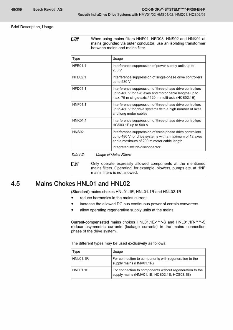
When using mains filters HNF01, NFD03, HNS02 and HNK01 atmains grounded via outer conductor, use an isolating transformerbetween mains and mains filter.
Type Usage
NFE01.1 Interference suppression of power supply units up to230 V
NFE02.1 Interference suppression of single-phase drive controllersup to 230 V
NFD03.1 Interference suppression of three-phase drive controllersup to 480 V for 1–6 axes and motor cable lengths up tomax. 75 m single-axis / 120 m multi-axis (HCS02.1E)
HNF01.1 Interference suppression of three-phase drive controllersup to 480 V for drive systems with a high number of axesand long motor cables
HNK01.1 Interference suppression of three-phase drive controllersHCS03.1E up to 500 V
HNS02 Interference suppression of three-phase drive controllersup to 480 V for drive systems with a maximum of 12 axesand a maximum of 200 m motor cable lengthIntegrated switch-disconnector
Tab.4-2: Usage of Mains Filters
Only operate expressly allowed components at the mentionedmains filters. Operating, for example, blowers, pumps etc. at HNFmains filters is not allowed.
4.5 Mains Chokes HNL01 and HNL02(Standard) mains chokes HNL01.1E, HNL01.1R and HNL02.1R● reduce harmonics in the mains current● increase the allowed DC bus continuous power of certain converters● allow operating regenerative supply units at the mains Current-compensated mains chokes HNL01.1E-****-S and HNL01.1R-****-Sreduce asymmetric currents (leakage currents) in the mains connectionphase of the drive system. The different types may be used exclusively as follows:
Type Usage
HNL01.1R For connection to components with regeneration to thesupply mains (HMV01.1R)
HNL01.1E For connection to components without regeneration to thesupply mains (HMV01.1E, HCS02.1E, HCS03.1E)
Bosch Rexroth AG DOK-INDRV*-SYSTEM*****-PR06-EN-P Rexroth IndraDrive Drive Systems with HMV01/02 HMS01/02, HMD01, HCS02/03
48/309
Brief Description, Usage

Type Usage
HNL01.1*-****-S Current-compensated chokes for use with HNL01.1 mainschokes to reduce asymmetric currents (leakage currents)in the mains connection phase of the drive system(HMV01.1E, HMV01.1R, HCS02.1E, HCS03.1E)
HNL02.1R Mains chokes in housing for control cabinet mounting forconnection to components with regeneration to the supplymains (HMV02.1R)
Tab.4-3: Usage of Mains Chokes
4.6 Supply Units HMV01 / HMV02HMV supply units supply modular HMS and HMD drive controllers.
Type Usage
HMV01.1E InfeedingSupplies HMS01 and HMD01 drive controllers
HMV01.1R RegenerativeSupplies HMS01 and HMD01 drive controllers
HMV02.1R RegenerativeSupplies HMS01, HMS02 and HMD01 drive controllers
Tab.4-4: Usage of Supply Units
4.7 Drive Controllers HMS01, HMS02 and HMD01In the modular drive system, HMS and HMD drive controllers control singleand double axes.
Type Usage
HMD01.1 ● Have two power outputs to operate two motors independently ofeach other
● Are operated at HMV supply units and HCS drive controllers
HMS01.1 ● Have a power output to operate a motor● Are operated at HMV01 supply units and HCS02 and HCS03
drive controllers
HMS02.1 ● Have a power output to operate a motor● Are operated at HMV02 supply units and HCS02 drive control‐
lers
Tab.4-5: Usage of HM* Drive Controllers
4.8 Control Sections CSB, CSE, CSH, CDBCSB, CSE, CSH and CDB control sections:● Allow operating HCS, HMS, HMD drive controllers● Fulfill open-loop and closed-loop control tasks with analog command
value input● Require a certain firmware:
– CSB01, CSH01, CDB01: ≤ MPx08
DOK-INDRV*-SYSTEM*****-PR06-EN-P Rexroth IndraDrive Drive Systems with HMV01/02 HMS01/02, HMD01, HCS02/03
Bosch Rexroth AG 49/309
Brief Description, Usage

– CSB02, CSH02, CDB02, CSE02: ≥ MPx18
Type Usage
CSHAdvancedIn HMS01, HMS02, HCS02, HCS03 drive controllers
CSBBASIC - single-axisIn HMS01, HMS02, HCS02, HCS03 drive controllers
CSEECONOMY - single-axisIn HMS01, HMS02, HCS02, HCS03 drive controllers
CDBBASIC - double-axisIn HMD01 drive controllers
Tab.4-6: Usage of Control Sections
4.9 Drive Controllers HCS02HCS02 drive controllers control single axes.
Type Usage
HCS02 ● Have a power output to operate a motor● Power range: 1.5 kW to 11 kW
Tab.4-7: Usage of HCS02 Drive Controllers
4.10 Drive Controllers HCS03HCS03 drive controllers control single axes.
Type Usage
HCS03 ● Have a power output to operate a motor● Power range: 18.5 kW to 75 kW
Tab.4-8: Usage of HCS03 Drive Controllers
In their standard design -NNNV, HCS03 drive controllers are notregenerative.For applications where regenerative power is generated, useHCS03.1 of the -NNBV design and HLR braking resistors.
4.11 Components KCU, KSM, KMSType Usage
KCU01 Drive connection box to connect KSM01/KMS01 to HMV supply unitsor HCS converters
KCU02 Drive connection box to connect KSM02/KMS02 to HMV supply unitsor HCS converters
Bosch Rexroth AG DOK-INDRV*-SYSTEM*****-PR06-EN-P Rexroth IndraDrive Drive Systems with HMV01/02 HMS01/02, HMD01, HCS02/03
50/309
Brief Description, Usage

Type Usage
KSM01KSM02
Motor-integrated servo drives: Synchronous servo motors (on the ba‐sis of Rexroth IndraDyn S) with integrated inverters and control sec‐tions
KMS01KMS02
Near motor servo drives: Very compact inverters with control sections
Tab.4-9: Components KCU, KSM, KMS
4.12 DC Bus Resistor Unit HLB01DC bus resistor units HLB01● Convert generated kinetic energy into thermal energy● Increase the continuous regenerative power in the drive system● Increase the peak regenerative power in the drive system● Allow the DC bus short circuit function ("ZKS") in the drive system
Type Usage
HLB01.1C In drive systems of the Rexroth IndraDrive C product range with a de‐vice mounting depth of 265 mm.
HLB01.1D In drive systems of the Rexroth IndraDrive M product range with a de‐vice mounting depth of 322 mm.
Tab.4-10: DC Bus Resistor Units HLB
4.13 Braking Resistor HLR01HLR01.1N‑xxxx‑Nxxx‑A‑007‑NNNN braking resistors convert generated ki‐netic energy into thermal energy. For this purpose, the line covers a widerange of continuous power and energy absorption capacity.
Type Usage
HLR01.1A Type of construction A (version for device mounting): Tobe mounted to drive controllers of the Rexroth IndraDriveC product range. For this purpose, the drive controllersmust be equipped with a brake chopper.
HLR01.1N Type of construction N (version for free assembly): Forfree assembly in the installation, operated by drive control‐ler of the Rexroth IndraDrive C product range. For this pur‐pose, the drive controllers must be equipped with a brakechopper.
Tab.4-11: Braking Resistors HLRDesigns of type of construction N:● Fixed resistor IP 20 type A
Cement-coated, wire-wound, tube-type fixed resistors; screwed on sidewalls; perforated cover; connections in terminal box with PG gland
● Steel-grid fixed resistor IP 20 type BFixed resistor in steel-grid design; connection depending on type
● Steel-grid fixed Resistor IP 20 type CFixed resistor in steel-grid design; connection depending on type
DOK-INDRV*-SYSTEM*****-PR06-EN-P Rexroth IndraDrive Drive Systems with HMV01/02 HMS01/02, HMD01, HCS02/03
Bosch Rexroth AG 51/309
Brief Description, Usage

4.14 DC Bus Capacitor Unit HLC01DC bus capacitor units HLC01 store energy in the DC bus of the drive sys‐tem.
Type Usage
HLC01.1C In drive systems of the product ranges RexrothIndraDrive C and Rexroth IndraDrive M
HLC01.1D In drive systems of the product ranges RexrothIndraDrive C and Rexroth IndraDrive M
Tab.4-12: DC Bus Capacitor Units HLC
4.15 Fan Unit HAB01HAB01 fan units cool specific HMV01 and HMS01 devices.
Type Usage
HAB01.1 At HMS01.1N-W0350 drive controllersAt HMV01.1R-W0120 supply units
Tab.4-13: Usage of HAB01 Fan Unit
4.16 Motor Filters HMF01HMF01 motor filters● reduce the rise of the output voltage of drive controllers● reduce leakage currents of the motor lines● reduce interference voltage on the motor lines
Type Usage
HMF01.1 At the motor output of HCS drive controllers
Tab.4-14: Usage of HMF01 Motor Filters
4.17 Accessories HASThe HAS accessories support the operation and combination of componentsin the Rexroth IndraDrive system.
4.18 Housing for Control Sections HAC01Additional components HAC01 are used to● insert control sections in them● supply control sections with 24V control voltage
Type Usage
HAC01.1-002-NNN-NN To insert CDB control sections in it
Tab.4-15: HAC01 Type
4.19 Hall Sensor Box SHLThe additional component SHL is used when the commutation setting of line‐ar motors (e.g., IndraDyn L and LSF) is to be carried out, mechanical move‐
Bosch Rexroth AG DOK-INDRV*-SYSTEM*****-PR06-EN-P Rexroth IndraDrive Drive Systems with HMV01/02 HMS01/02, HMD01, HCS02/03
52/309
Brief Description, Usage

ment mustn't take place and the automatic commutation methods of the drivefirmware cannot be used.The drive firmware provides automatic commutation methods which can beused for sophisticated motion tasks.
See also Functional Description of the firmware, index entry "Saturationmethod" (requires Iout_max) and "Sine-wave method" (requires unrestrictedmovement of the axis).
DOK-INDRV*-SYSTEM*****-PR06-EN-P Rexroth IndraDrive Drive Systems with HMV01/02 HMS01/02, HMD01, HCS02/03
Bosch Rexroth AG 53/309
Brief Description, Usage

Bosch Rexroth AG DOK-INDRV*-SYSTEM*****-PR06-EN-P Rexroth IndraDrive Drive Systems with HMV01/02 HMS01/02, HMD01, HCS02/03
54/309
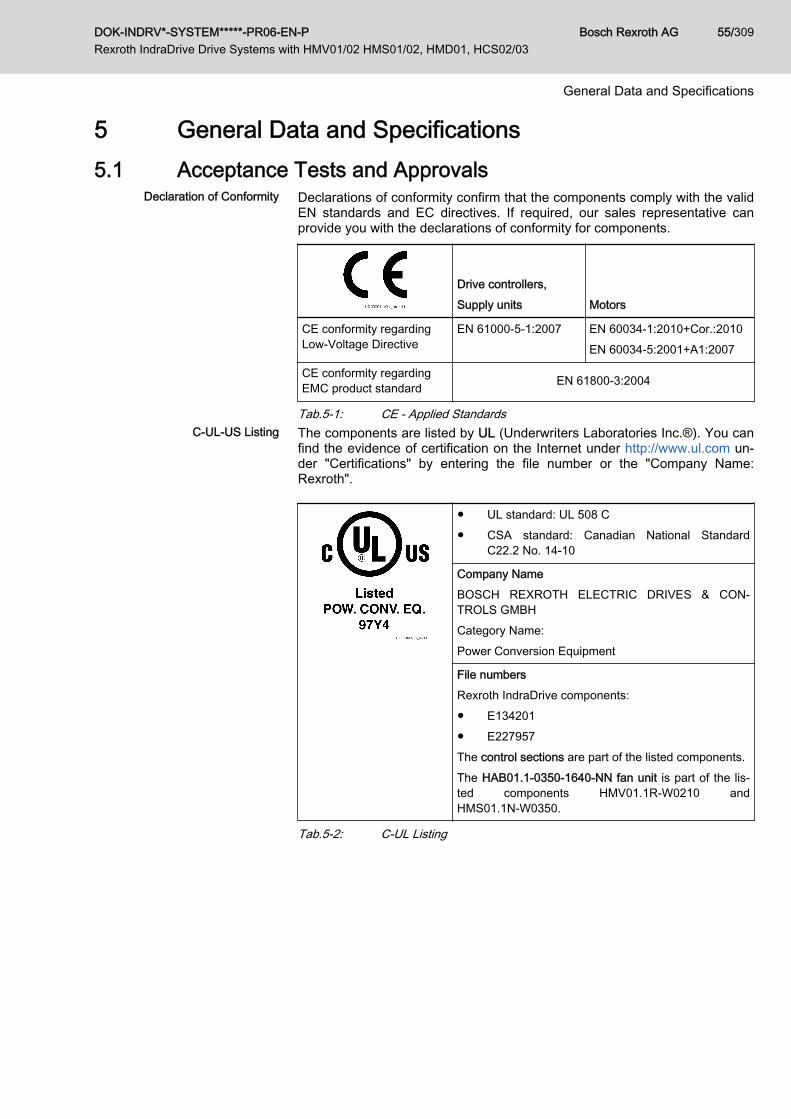
5 General Data and Specifications5.1 Acceptance Tests and Approvals
Declaration of Conformity Declarations of conformity confirm that the components comply with the validEN standards and EC directives. If required, our sales representative canprovide you with the declarations of conformity for components.
Drive controllers,Supply units Motors
CE conformity regardingLow-Voltage Directive
EN 61000-5-1:2007 EN 60034-1:2010+Cor.:2010EN 60034-5:2001+A1:2007
CE conformity regardingEMC product standard EN 61800-3:2004
Tab.5-1: CE - Applied StandardsC-UL-US Listing The components are listed by UL (Underwriters Laboratories Inc.®). You can
find the evidence of certification on the Internet under http://www.ul.com un‐der "Certifications" by entering the file number or the "Company Name:Rexroth".
● UL standard: UL 508 C● CSA standard: Canadian National Standard
C22.2 No. 14-10
Company NameBOSCH REXROTH ELECTRIC DRIVES & CON‐TROLS GMBHCategory Name:Power Conversion Equipment
File numbersRexroth IndraDrive components:● E134201● E227957The control sections are part of the listed components.The HAB01.1-0350-1640-NN fan unit is part of the lis‐ted components HMV01.1R‑W0210 andHMS01.1N‑W0350.
Tab.5-2: C-UL Listing
DOK-INDRV*-SYSTEM*****-PR06-EN-P Rexroth IndraDrive Drive Systems with HMV01/02 HMS01/02, HMD01, HCS02/03
Bosch Rexroth AG 55/309
General Data and Specifications

UL ratingsFor using the component in the scope of CSA / UL, take the ULratings of the individual components into account.In the scope of CSA / UL, it is exclusively the following compo‐nents which have been approved to supply the components HMS,HMD, KCU, KSM, KMS:● HMV01.1E● HMV01.1R● HMV02.1R● HCS02.1E● HCS03.1EMake sure that the indicated short circuit current rating SCCR isnot exceeded, e.g. by appropriate fuses in the mains supply of thesupply unit.
Wiring material ULIn the scope of CSA / UL, use copper 60/75 °C only; class 1 orequivalent only.
Allowed pollution degreeComply with the allowed pollution degree of the components (see"Ambient and Operating Conditions").
C-UR-US Listing The motors are listed by UL ("Underwriters Laboratories Inc.®"). You can findthe evidence of certification on the Internet under http://www.ul.com under"Certifications" by entering the file number or the "Company Name: Rexroth".
● UL standard: UL 1004-1● CSA standard: Canadian National
Standard C22.2 No. 100
Company NameBOSCH REXROTH ELECTRIC DRIVES &CONTROLS GMBHCategory Name:Servo and Stepper Motors - Component
File numbersMSK, MSM motors: E335445
Tab.5-3: C-UR Listing
Wiring material UL (ready-made cables by Rexroth)In the scope of CSA / UL, use copper 60/75 °C only; class 6 orequivalent only.
Allowed pollution degreeComply with the allowed pollution degree of the components (see"Ambient and Operating Conditions").
Bosch Rexroth AG DOK-INDRV*-SYSTEM*****-PR06-EN-P Rexroth IndraDrive Drive Systems with HMV01/02 HMS01/02, HMD01, HCS02/03
56/309
General Data and Specifications

CCC (China Compulsory Certifica‐tion)
The CCC test symbol comprises a compulsory certification of safety andquality for certain products mentioned in the product catalog "First Catalogueof Products Subject to Compulsory Certification" and in the CNCA document"Application Scope for Compulsory Certification of Products acc. first Cata‐logue" and put in circulation in China. This compulsory certification has beenexisting since 2003.CNCA is the Chinese authority responsible for certification directives. When aproduct is imported in China, the certification will be checked at the customsby means of entries in a database. For the requirement of certification threecriteria are normally relevant:1. Customs tariff number (HS code) according to CNCA document "Appli‐
cation Scope for Compulsory Certification of Products acc. first Cata‐logue".
2. Scope of application according to CNCA document "Application Scopefor Compulsory Certification of Products acc. first Catalogue".
3. For the IEC product standard used, the corresponding Chinese GBstandard must exist.
For the drive components by Rexroth described in this documentation, certifi‐cation is not required at present, thus they are not CCC certified. Negativecertifications will not be issued.
5.2 Transport and Storage5.2.1 Transport of the Components
Ambient and Operating Conditions - Transport
Description Symbol Unit Value
Temperature range Ta_tran °C Supply units and drive con‐trollers:KCU:
-25 … +70
Motors:KSM, KMS:-20 … +80
Relative humidity % 5 … 95
Absolute humidity g/m3 1 … 60
Climatic category (IEC 721) 2K3
Moisture condensation Not allowed
Icing Not allowed
Tab.5-4: Ambient and Operating Conditions - Transport
DOK-INDRV*-SYSTEM*****-PR06-EN-P Rexroth IndraDrive Drive Systems with HMV01/02 HMS01/02, HMD01, HCS02/03
Bosch Rexroth AG 57/309
General Data and Specifications

5.2.2 Storage of the Components
Damage to the component caused by longstorage periods!
NOTICE
Some components contain electrolytic capacitors which may deteriorate dur‐ing storage.When storing the following components for a longer period of time, operatethem once a year for at least 1 hour:● Converters and supply units: Operation with mains voltage ULN
● Inverters and DC bus capacitor units: Operation with DC bus voltageUDC
Risk of damage to the drive connection boxKCU by extended storage!
NOTICE
The drive connection box KCU contains electrolytic capacitors which may de‐teriorate during storage. When storing the drive connection box KCU for alonger period of time, operate it once a year for at least 1 hour with 24 V con‐trol voltage UN3.
Ambient and Operating Conditions - Storage
Description Symbol Unit Value
Temperature range Ta_store °C Supply units and drive con‐trollers:KCU:
-25 … 55
Motors:KSM, KMS:-20 … +60
Relative humidity % 5 … 95
Absolute humidity g/m3 1 … 29
Climatic category (IEC721) 1K3
Moisture condensation Not allowed
Icing Not allowed
Tab.5-5: Ambient and Operating Conditions - Storage
5.3 Installation Conditions5.3.1 Ambient and Operating Conditions
Check that the ambient conditions, in particular the control cabi‐net temperature, are complied with by calculating the heat levelsin the control cabinet. Afterwards, make the corresponding meas‐urements to find out that the ambient conditions have actuallybeen complied with.In the technical data of the individual components, the power dis‐sipation is indicated as an important input value for calculating theheat levels.
Motor-integrated servo drives KSM and near motor servo drives KMS are de‐signed for use near to the machines and are not installed in control cabinets.
Bosch Rexroth AG DOK-INDRV*-SYSTEM*****-PR06-EN-P Rexroth IndraDrive Drive Systems with HMV01/02 HMS01/02, HMD01, HCS02/03
58/309
General Data and Specifications

Ambient and Operating Conditions (HCS, HMV, HMS, HMD, HCQ, HCT,KCU, HLC)
Description Symbol Unit Value
Conductive dirt contamination Not allowedProtected the devices against conductive dirt con‐tamination by mounting them in control cabinets ofthe degree of protection IP54 (in accordance with
IEC 60529).
Degree of protection of the device (IEC 60529) IP20
Use in the scope of CSA / UL For use in NFPA 79 Applications only.
Temperature during storage See chapter 5.2.2 "Storage of the Components" onpage 58
Temperature during transport See chapter 5.2.1 "Transport of the Components" onpage 57
Allowed mounting positionDefinition of mounting positions: See chapter"Mounting Positions of Components" on page62
G1
Installation altitude hnenn m 1000
Ambient temperature range Ta_work °C 0 … 40
Derating vs. ambient temperature:In the ambient temperature range Ta_work_red, theperformance data are reduced by the factor FTa:
FTa = 1 - [(Ta - 40) × fTa]
For the drive connection box KCU, the ratedpower (Pout) is reduced at the output of the 42 Vcontrol voltage. The rated power at the output ofthe power section (PDC_cont) is not reduced.
Example: With an ambient temperatureTa = 50 °C and a capacity utilization factorfTa = 2 %/K, the rated power is reduced to
PDC_cont_red = PDC_cont × FTa =
PDC_cont × (1 - [(50 - 40) × 0.02]) = PDC_cont × 0.8
Operation at ambient temperatures outside ofTa_work and Ta_work_red is not allowed!
Ta_work_red °C 40 … 55
fTa %/K 2,0Exception HMV02.1R-W0015-A-07-NNNN:
2,7
DOK-INDRV*-SYSTEM*****-PR06-EN-P Rexroth IndraDrive Drive Systems with HMV01/02 HMS01/02, HMD01, HCS02/03
Bosch Rexroth AG 59/309
General Data and Specifications

Description Symbol Unit Value
Derating vs. installation altitude:With installation altitudes h > hnenn, the availableperformance data are reduced by the factor f3)
4).With installation altitudes in the range ofhmax_ohne to hmax, an overvoltage limiter againsttransient overvoltage must be installed in the in‐stallation.Operation above hmax is not allowed! hmax_ohne m 2000
hmax m 4000
Simultaneous derating for ambient temperatureand installation altitude
Allowed;reduce performance data with the product f × FTa
Relative humidity % 5 … 95
Absolute humidity g/m3 1 … 29
Climatic category (IEC721) 3K3
Allowed pollution degree (IEC 60664‑1) 2
Allowed dust, steam EN 50178 tab. A.2
Vibration sine: Amplitude (peak-peak) at 5 … 32Hz2)
mm 0,6 ±15%
Vibration sine: Acceleration at 32 … 200 Hz2) g 1,3 ±15%
Vibration noise (random) frequency1) Hz 20 … 500
Vibration noise (random) spectral accelerationdensity, amplitude1)
g2/Hz 0,05
Vibration noise (random) rms value of total ac‐celeration 1)
g 1,5
Vibration sine: Axial
Acceleration at 10 … 2,000 Hz2)
g -
Vibration sine: Radial
Acceleration at 10 … 2,000 Hz2)
g -
Overvoltage category III (according to IEC60664-1)
1) According to EN 60068-2-642) According to EN 60068-2-63) Reduced performance data for drive controllers: Allowed DC bus con‐
tinuous power, braking resistor continuous power, continuous current;for HCS01, HCQ, HCT drive controllers additionally: Allowed mainsvoltage
4) Reduced performance data for motors: Performance, torque S1 andS3
Tab.5-6: Ambient and Operating Conditions (HCS, HMV, HMS, HMD, HCQ,HCT, KCU, HLC)
Bosch Rexroth AG DOK-INDRV*-SYSTEM*****-PR06-EN-P Rexroth IndraDrive Drive Systems with HMV01/02 HMS01/02, HMD01, HCS02/03
60/309
General Data and Specifications

Ambient and Operating Conditions (KSM, KMS)
Description Symbol Unit Value
Degree of protection (IEC 60529) IP65
Use in the scope of CSA / UL For use in NFPA 79 Applications only.
Temperature during storage See chapter 5.2.2 "Storage of the Components" onpage 58
Temperature during transport See chapter 5.2.1 "Transport of the Components" onpage 57
Allowed mounting positionDefinition of mounting positions: See chapter"Mounting Positions of Components" on page62
KSM: IM B5, IM V1, IM V3KMS: G1, G2, G3, G4, G5
Installation altitude hnenn m 1000
Ambient temperature range Ta_work °C 0 … 40
Derating vs. ambient temperature:In the ambient temperature range Ta_work_red, theperformance data are reduced by the factor FTa:
FTa = 1 - [(Ta - 40) × fTa]
Example: With an ambient temperatureTa = 50 °C and a capacity utilization factorfTa = 3 %/K, the rated power is reduced to
PDC_cont_red = PDC_cont × FTa =
PDC_cont × (1 - [(50 - 40) × 0.03]) = PDC_cont × 0.7
Operation at ambient temperatures outside ofTa_work and Ta_work_red is not allowed!
Ta_work_red °C 40 … 55
fTa %/K 3
Derating vs. installation altitude:With installation altitudes h > hnenn, the availableperformance data are reduced by the factor f3)
4).With installation altitudes in the range ofhmax_ohne to hmax, an overvoltage limiter againsttransient overvoltage must be installed in the in‐stallation.Operation above hmax is not allowed! hmax_ohne m 2000
hmax m 4000
Simultaneous derating for ambient temperatureand installation altitude
Allowed;reduce performance data with the product of the factors f and FTa
(f × FTa)
Relative humidity % 5 … 95
Absolute humidity g/m3 1 … 29
Climatic category (IEC721) 3K4
Allowed pollution degree (IEC 60664‑1) 3 (only with connectors plugged in)
DOK-INDRV*-SYSTEM*****-PR06-EN-P Rexroth IndraDrive Drive Systems with HMV01/02 HMS01/02, HMD01, HCS02/03
Bosch Rexroth AG 61/309
General Data and Specifications
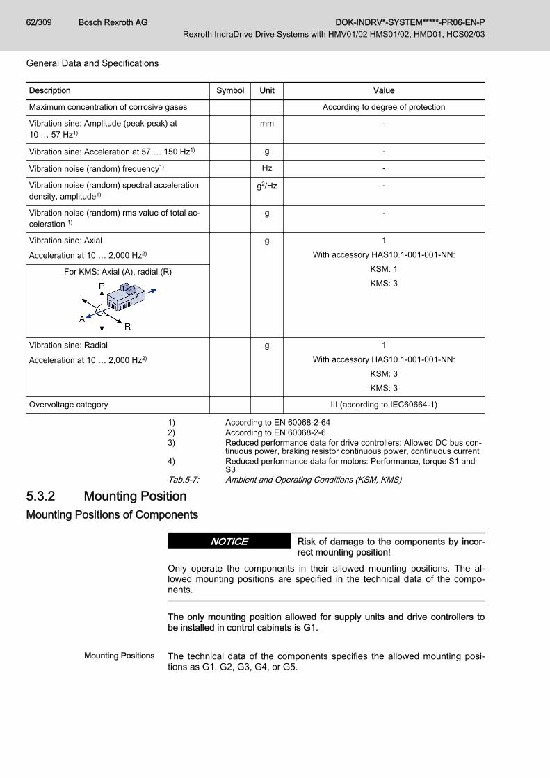
Description Symbol Unit Value
Maximum concentration of corrosive gases According to degree of protection
Vibration sine: Amplitude (peak-peak) at10 … 57 Hz1)
mm -
Vibration sine: Acceleration at 57 … 150 Hz1) g -
Vibration noise (random) frequency1) Hz -
Vibration noise (random) spectral accelerationdensity, amplitude1)
g2/Hz -
Vibration noise (random) rms value of total ac‐celeration 1)
g -
Vibration sine: Axial
Acceleration at 10 … 2,000 Hz2)
g 1With accessory HAS10.1-001-001-NN:
KSM: 1KMS: 3
For KMS: Axial (A), radial (R)
Vibration sine: Radial
Acceleration at 10 … 2,000 Hz2)
g 1With accessory HAS10.1-001-001-NN:
KSM: 3KMS: 3
Overvoltage category III (according to IEC60664-1)
1) According to EN 60068-2-642) According to EN 60068-2-63) Reduced performance data for drive controllers: Allowed DC bus con‐
tinuous power, braking resistor continuous power, continuous current4) Reduced performance data for motors: Performance, torque S1 and
S3Tab.5-7: Ambient and Operating Conditions (KSM, KMS)
5.3.2 Mounting PositionMounting Positions of Components
Risk of damage to the components by incor‐rect mounting position!
NOTICE
Only operate the components in their allowed mounting positions. The al‐lowed mounting positions are specified in the technical data of the compo‐nents.
The only mounting position allowed for supply units and drive controllers tobe installed in control cabinets is G1.
Mounting Positions The technical data of the components specifies the allowed mounting posi‐tions as G1, G2, G3, G4, or G5.
Bosch Rexroth AG DOK-INDRV*-SYSTEM*****-PR06-EN-P Rexroth IndraDrive Drive Systems with HMV01/02 HMS01/02, HMD01, HCS02/03
62/309
General Data and Specifications
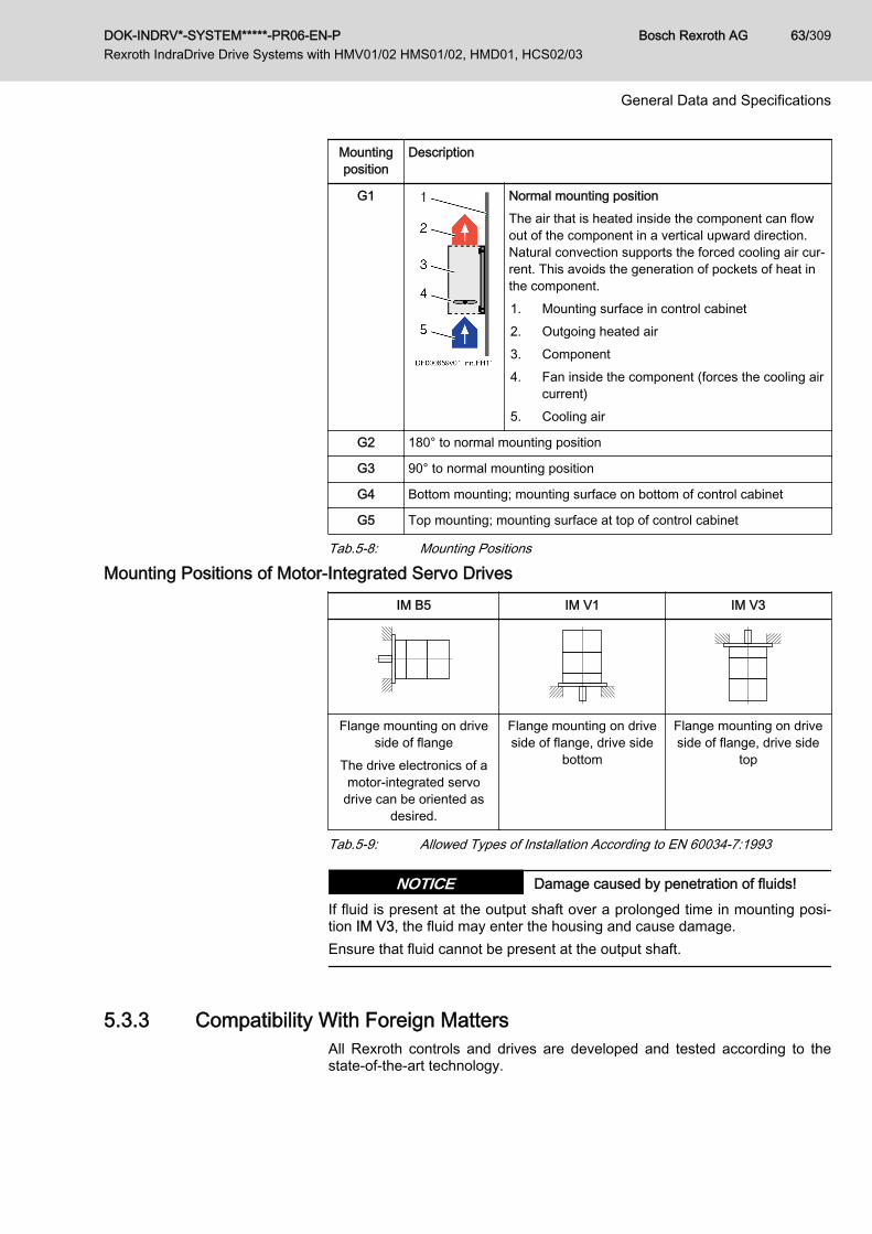
Mountingposition
Description
G1 Normal mounting positionThe air that is heated inside the component can flowout of the component in a vertical upward direction.Natural convection supports the forced cooling air cur‐rent. This avoids the generation of pockets of heat inthe component.1. Mounting surface in control cabinet2. Outgoing heated air3. Component4. Fan inside the component (forces the cooling air
current)5. Cooling air
G2 180° to normal mounting position
G3 90° to normal mounting position
G4 Bottom mounting; mounting surface on bottom of control cabinet
G5 Top mounting; mounting surface at top of control cabinet
Tab.5-8: Mounting Positions
Mounting Positions of Motor-Integrated Servo DrivesIM B5 IM V1 IM V3
Flange mounting on driveside of flange
The drive electronics of amotor-integrated servo
drive can be oriented asdesired.
Flange mounting on driveside of flange, drive side
bottom
Flange mounting on driveside of flange, drive side
top
Tab.5-9: Allowed Types of Installation According to EN 60034-7:1993
Damage caused by penetration of fluids!NOTICEIf fluid is present at the output shaft over a prolonged time in mounting posi‐tion IM V3, the fluid may enter the housing and cause damage.Ensure that fluid cannot be present at the output shaft.
5.3.3 Compatibility With Foreign MattersAll Rexroth controls and drives are developed and tested according to thestate-of-the-art technology.
DOK-INDRV*-SYSTEM*****-PR06-EN-P Rexroth IndraDrive Drive Systems with HMV01/02 HMS01/02, HMD01, HCS02/03
Bosch Rexroth AG 63/309
General Data and Specifications

As it is impossible to follow the continuing development of all materials (e.g.lubricants in machine tools) which may interact with the controls and drives, itcannot be completely ruled out that any reactions with the materials we usemight occur.For this reason, before using the respective material a compatibility test hasto be carried out for new lubricants, cleaning agents etc. and our housings/materials.
5.3.4 Motor Paint CoatColor Black (RAL9005)
Resistance Resistant to
● Diluted acids and lyes● Water, sea water, waste water● Common mineral oilsIn restricted form resistant to● Organic solvents● Hydraulic oilNonresistant to● Concentrated acids/lyes
Additional paint coat Allowed for:Standard productsIt is permitted to provide the housing with an additional paint coat having amaximum thickness of 40 µm. Before applying the paint coat, verify the adhe‐sion and resistance of the new coat.
When applying a paint coat subsequently, provide paint protectionon all safety labels, type plates and open plug-in connectors. Thefunctionality of the motor may not be restricted by the additionalpaint coat.
Not allowed for:Products for explosive atmospheresIt is not allowed to provide motors in Ex design with additional paint coats inorder to prevent negative effects on surface properties (such as insulation re‐sistance, electrostatic charge).
5.4 Voltage Test and Insulation Resistance TestAccording to standard, the components of the Rexroth IndraDrive range aretested with voltage.
Test Test rate
Voltage test 100% (EN 61800-5-1)
Insulation resistance test 100% (EN 60204-1)
Tab.5-10: Applied Standards
Bosch Rexroth AG DOK-INDRV*-SYSTEM*****-PR06-EN-P Rexroth IndraDrive Drive Systems with HMV01/02 HMS01/02, HMD01, HCS02/03
64/309
General Data and Specifications
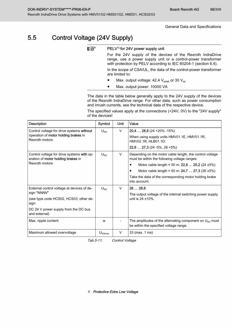
5.5 Control Voltage (24V Supply) PELV1) for 24V power supply unitFor the 24V supply of the devices of the Rexroth IndraDriverange, use a power supply unit or a control-power transformerwith protection by PELV according to IEC 60204-1 (section 6.4).In the scope of CSA/UL, the data of the control-power transformerare limited to:● Max. output voltage: 42.4 Vpeak or 30 Vac
● Max. output power: 10000 VA
The data in the table below generally apply to the 24V supply of the devicesof the Rexroth IndraDrive range. For other data, such as power consumptionand inrush currents, see the technical data of the respective device.The specified values apply at the connections (+24V, 0V) to the "24V supply"of the devices!
Description Symbol Unit Value
Control voltage for drive systems withoutoperation of motor holding brakes inRexroth motors
UN3 V 20,4 … 28,8 (24 +20% -15%)When using supply units HMV01.1E, HMV01.1R,HMV02.1R, HLB01.1D:22,8 … 27,3 (24 ‑5%, 26 +5%)
Control voltage for drive systems with op‐eration of motor holding brakes inRexroth motors
UN3 V Depending on the motor cable length, the control voltagemust be within the following voltage ranges:● Motor cable length < 50 m: 22,8 … 25,2 (24 ±5%)● Motor cable length > 50 m: 24,7 … 27,3 (26 ±5%)Take the data of the corresponding motor holding brakeinto account.
External control voltage at devices of de‐sign "NNNV"(see type code HCS02, HCS03; other de‐sign:DC 24 V power supply from the DC busand external)
UN3 V 26 … 28,8The output voltage of the internal switching power supplyunit is 24 ±10%.
Max. ripple content w - The amplitudes of the alternating component on UN3 mustbe within the specified voltage range.
Maximum allowed overvoltage UN3max V 33 (max. 1 ms)
Tab.5-11: Control Voltage
1) Protective Extra Low Voltage
DOK-INDRV*-SYSTEM*****-PR06-EN-P Rexroth IndraDrive Drive Systems with HMV01/02 HMS01/02, HMD01, HCS02/03
Bosch Rexroth AG 65/309
General Data and Specifications

Description Symbol Unit Value
Control voltage for drive systems UN3 V 20,4 … 28,8 (24 +20% -15%)When using supply units HMV01.1E, HMV01.1R,HMV02.1R, HLB01.1D:22,8 … 27,3 (24 ‑5%, 26 +5%)
Max. ripple content w - The amplitudes of the alternating component on UN3 mustbe within the specified voltage range.
Maximum allowed overvoltage UN3max V 33 (max. 1 ms)
Tab.5-12: Control Voltage
OvervoltageOvervoltage greater than 33 V has to be discharged by means ofthe appropriate electrical equipment of the machine or installation.This includes:● 24V power supply units that reduce incoming overvoltage to
the allowed value.● Overvoltage limiters at the control cabinet input that limit ex‐
isting overvoltage to the allowed value. This, too, applies tolong 24V lines that have been run in parallel to power cablesand mains cables and can absorb overvoltage by inductiveor capacitive coupling.
Insulation monitoring impossibleThe input 0 V is connected in conductive form to the housing po‐tential. Insulation monitoring at +24 V and 0 V against housing isimpossible.
Bosch Rexroth AG DOK-INDRV*-SYSTEM*****-PR06-EN-P Rexroth IndraDrive Drive Systems with HMV01/02 HMS01/02, HMD01, HCS02/03
66/309
General Data and Specifications
6 Project Planning of Control Voltage (24V Supply)6.1 General Information
To operate the drive system, supply the devices with control voltage. For theproject planning of the 24V supply of the drive system, take the requirementsof the devices used into account:● Voltage and voltage tolerances depending on line lengths and use of
holding brake.See also chapter 5.5 "Control Voltage (24V Supply) " on page 65
● Power consumption of the drive controllers with control section andpower section
● Power consumption of other components, e.g. holding brakes● Current carrying capacity of the connections for "looping through"● Buffering the control voltage supply might possibly be necessary
For the requirements of the supply units and converters, see ProjectPlanning Manual "Rexroth IndraDrive Supply Units and Power Sections" →Chapter of the respective device → "Technical Data" → "Basic Data" → table"Data for Control Voltage Supply".
6.2 Selecting the 24V Supply6.2.1 General Information
The components need the 24V supply for correct operation. At componentsof the Rexroth IndraDrive range, the external 24V supply takes place via theconnection X13 or via the connections 24V and 0V at the terminal block.Via these connections, the components are supplied with 24V for● the power section of the drive controller or supply unit● brake control via X6● the control section of the drive controller
In particular, take mains failure situations into account and usepower supply units with buffer (UPS), if necessary.The inputs/outputs of the I/O extensions MA1, MD1 and MD2 arenot supplied with voltage via the control section, but have theirown connections.Take the additional power required for these connections into ac‐count.
HCS02/HCS03 converters of the design "-N**V" have an integra‐ted 24V supply. In applications without motor holding brake andwith CSB01.1N‑FC control section, they can be operated withoutexternal 24V supply. Observe the notes on project planning forthe mains connection.
DOK-INDRV*-SYSTEM*****-PR06-EN-P Rexroth IndraDrive Drive Systems with HMV01/02 HMS01/02, HMD01, HCS02/03
Bosch Rexroth AG 67/309
Project Planning of Control Voltage (24V Supply)

D1, D2 Diodes, internalD3 Protective diode, externalLT Power sectionBR Circuit motor holding brakeST Control sectionOM1 Optional modulesOM2 Optional modules with supply voltage connection, e.g. MA1, MD2Fig.6-1: Block Diagram of 24V Supply
6.2.2 Electrical RequirementsThe following parameters contain the essential electrical requirements on thepower supply unit:● Output voltage or range of output voltage● Continuous power which the power supply unit must supply during oper‐
ation● Peak current which the power supply unit must supply when switching
onWhich Output Voltage Must the
Power Supply Unit Have?The output voltage of the power supply unit must have been dimensionedsuch that the voltage at the input of the devices ("24V supply": 24V; 0V) iswithin the allowed voltage UN3.
Take into account that due to voltage drops, the output voltage ofthe power supply unit is lower than the voltage at the devices.Check the voltage at the input of the "24V supply" of the devices.Use power supply units● with adjustable output voltage from 24 V to 26 V● which have been equipped with Sense inputs (this allows
compensating for the voltage drops on the line betweenpower supply unit and input "24V supply")
See Project Planning Manual "Rexroth IndraDrive Supply Units and Pow‐er Sections" → Chapter of the respective device → "Technical Data" → "BasicData" → "Data for Control Voltage Supply".
Bosch Rexroth AG DOK-INDRV*-SYSTEM*****-PR06-EN-P Rexroth IndraDrive Drive Systems with HMV01/02 HMS01/02, HMD01, HCS02/03
68/309
Project Planning of Control Voltage (24V Supply)

Control voltage when using motor holding brakes!Depending on the motor cable length, a higher output voltage ofthe power supply unit is required for operating the motor holdingbrakes. Observe the data for operating motors with holdingbrakes (see chapter 5.5 "Control Voltage (24V Supply) " on page65).
Which Continuous Power Must thePower Supply Unit Supply?
The continuous power of the power supply unit must be greater than the sumof power consumptions PN3 of the components to be supplied.
For the power consumption PN3, see Project Planning Manual "RexrothIndraDrive Supply Units and Power Sections" → Chapter of the respective de‐vice → "Technical Data" → "Basic Data" → "Data for Control Voltage Supply".
For the power consumption of the control sections (basic control sectioncircuit board or optional modules), see Project Planning Manual "RexrothIndraDrive Control Sections" → index entry "Power consumption"If required, determine the continuous current IN3 for selecting the power sup‐ply unit:IN3 = PN3 / UN3
The power consumption is indicated as maximum value of the respectivecomponent and can occur at individual components.In drive systems with several components, the occurring power consumptionunder statistical assumptions will be lower than the calculated one.Experience has shown that the typical power consumption of drive systems isat only approx. 70% of the calculated maximum value.
Which Peak Current Must thePower Supply Unit Supply?
When switched on, the power supply unit must supply the sum of the occur‐ring inrush currents IEIN3 or charges IEIN3 × tEIN3Lade.When the power supply unit is switched on, the power supply unit is loadedwith the charging current to the capacitors of the 24V supply input of the con‐nected devices. An electronic circuit in each drive controller limits this charg‐ing current to the value IEIN3.
For the data of the inrush current IEIN3 and its pulse width tEIN3Lade for theindividual devices, see Project Planning Manual "Rexroth IndraDrive SupplyUnits and Power Sections" → Chapter of the respective device → "TechnicalData" → "Basic Data" → "Data for Control Voltage Supply".The occurring charging process IEIN3 × tEIN3Lade is controlled by power supplyunits with integrated dynamic current limitation, if the power supply units al‐low the 1.2-fold continuous current for at least 1 second. Therefore, use pow‐er supply units with integrated dynamic current limitation the continuous pow‐er of which is at least 20% above the determined sum of power consumptionsPN3.
Power supply units with buffer (UPS)For HMV supply units, use 24 V supplies with buffer times of atleast 100 ms (e.g. UPS), if commutation drops and short-time in‐terruptions in the application exceed the specified values.For the 24V supply, take notes on project planning of the mainsconnection into account (see chapter 7 "Project Planning ofMains Connection " on page 73).
DOK-INDRV*-SYSTEM*****-PR06-EN-P Rexroth IndraDrive Drive Systems with HMV01/02 HMS01/02, HMD01, HCS02/03
Bosch Rexroth AG 69/309
Project Planning of Control Voltage (24V Supply)

6.3 Installing the 24V SupplyAs a matter of principle, the 24V supply of the devices of the drive systemRexroth IndraDrive has to be designed in star-shaped form, i.e. for eachgroup of drive controllers or third-party components it is necessary to runseparate supply lines. This, too, applies to multiple-line arrangement in thecase of supply from a supply unit, for example.
A Device group, e.g. IndraDrive CB Device group, e.g. IndraDrive MC Third-party component (e.g. PLC, valve etc.)1) Connection to central ground point (e.g. earth-circuit connector)Fig.6-2: Installing the 24V Supply
If you use several power supply units for 24 V supply:● Interconnect reference conductors 0 V of the individual pow‐
er supply units with low impedance● The output voltages of the power supply units must be within
the allowed voltage range.● Switch the power supply units on and off synchronously.Reduce load-dependent voltage drops by using lines with suffi‐ciently dimensioned line cross sections.
Chronological Order of 24V Sup‐ply and Mains Voltage
Before mains voltage or DC bus voltage is applied to the devices, they haveto be supplied by the 24V supply.In this context, observe the chapter 9 Circuits for the Mains Connection, page141.
Bosch Rexroth AG DOK-INDRV*-SYSTEM*****-PR06-EN-P Rexroth IndraDrive Drive Systems with HMV01/02 HMS01/02, HMD01, HCS02/03
70/309
Project Planning of Control Voltage (24V Supply)
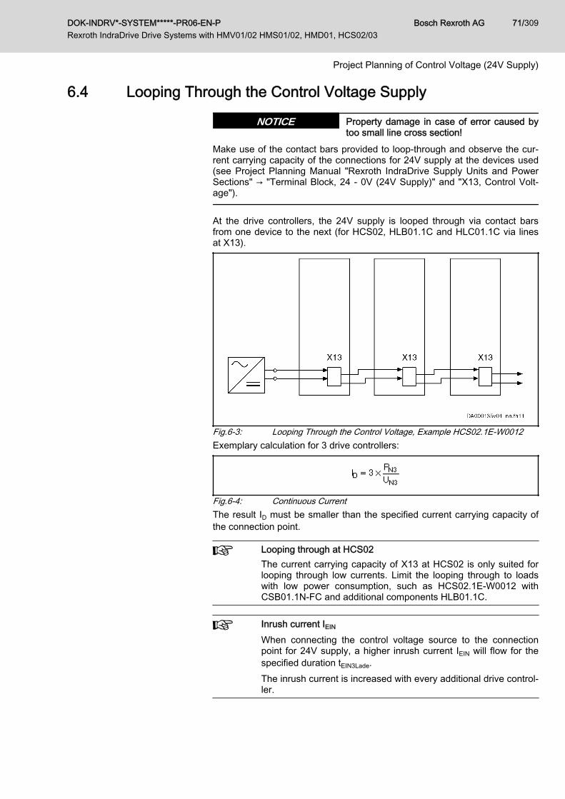
6.4 Looping Through the Control Voltage Supply
Property damage in case of error caused bytoo small line cross section!
NOTICE
Make use of the contact bars provided to loop-through and observe the cur‐rent carrying capacity of the connections for 24V supply at the devices used(see Project Planning Manual "Rexroth IndraDrive Supply Units and PowerSections" → "Terminal Block, 24 - 0V (24V Supply)" and "X13, Control Volt‐age").
At the drive controllers, the 24V supply is looped through via contact barsfrom one device to the next (for HCS02, HLB01.1C and HLC01.1C via linesat X13).
Fig.6-3: Looping Through the Control Voltage, Example HCS02.1E-W0012Exemplary calculation for 3 drive controllers:
Fig.6-4: Continuous CurrentThe result ID must be smaller than the specified current carrying capacity ofthe connection point.
Looping through at HCS02The current carrying capacity of X13 at HCS02 is only suited forlooping through low currents. Limit the looping through to loadswith low power consumption, such as HCS02.1E-W0012 withCSB01.1N-FC and additional components HLB01.1C.
Inrush current IEIN
When connecting the control voltage source to the connectionpoint for 24V supply, a higher inrush current IEIN will flow for thespecified duration tEIN3Lade.The inrush current is increased with every additional drive control‐ler.
DOK-INDRV*-SYSTEM*****-PR06-EN-P Rexroth IndraDrive Drive Systems with HMV01/02 HMS01/02, HMD01, HCS02/03
Bosch Rexroth AG 71/309
Project Planning of Control Voltage (24V Supply)

Bosch Rexroth AG DOK-INDRV*-SYSTEM*****-PR06-EN-P Rexroth IndraDrive Drive Systems with HMV01/02 HMS01/02, HMD01, HCS02/03
72/309
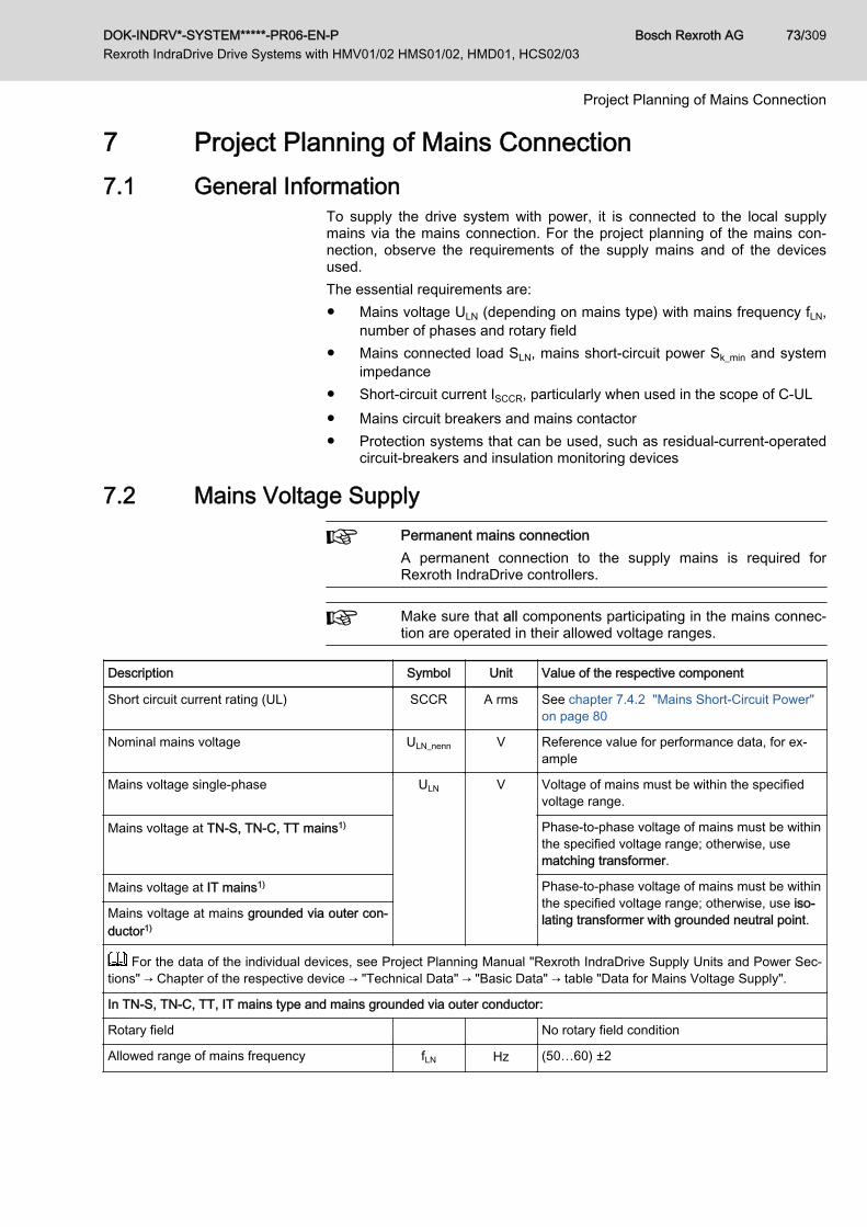
7 Project Planning of Mains Connection 7.1 General Information
To supply the drive system with power, it is connected to the local supplymains via the mains connection. For the project planning of the mains con‐nection, observe the requirements of the supply mains and of the devicesused.The essential requirements are:● Mains voltage ULN (depending on mains type) with mains frequency fLN,
number of phases and rotary field● Mains connected load SLN, mains short-circuit power Sk_min and system
impedance● Short-circuit current ISCCR, particularly when used in the scope of C-UL● Mains circuit breakers and mains contactor● Protection systems that can be used, such as residual-current-operated
circuit-breakers and insulation monitoring devices
7.2 Mains Voltage Supply Permanent mains connectionA permanent connection to the supply mains is required forRexroth IndraDrive controllers.
Make sure that all components participating in the mains connec‐tion are operated in their allowed voltage ranges.
Description Symbol Unit Value of the respective component
Short circuit current rating (UL) SCCR A rms See chapter 7.4.2 "Mains Short-Circuit Power"on page 80
Nominal mains voltage ULN_nenn V Reference value for performance data, for ex‐ample
Mains voltage single-phase ULN V Voltage of mains must be within the specifiedvoltage range.
Mains voltage at TN-S, TN-C, TT mains1) Phase-to-phase voltage of mains must be withinthe specified voltage range; otherwise, usematching transformer.
Mains voltage at IT mains1) Phase-to-phase voltage of mains must be withinthe specified voltage range; otherwise, use iso‐lating transformer with grounded neutral point.Mains voltage at mains grounded via outer con‐
ductor1)
For the data of the individual devices, see Project Planning Manual "Rexroth IndraDrive Supply Units and Power Sec‐tions" → Chapter of the respective device → "Technical Data" → "Basic Data" → table "Data for Mains Voltage Supply".
In TN-S, TN-C, TT, IT mains type and mains grounded via outer conductor:
Rotary field No rotary field condition
Allowed range of mains frequency fLN Hz (50…60) ±2
DOK-INDRV*-SYSTEM*****-PR06-EN-P Rexroth IndraDrive Drive Systems with HMV01/02 HMS01/02, HMD01, HCS02/03
Bosch Rexroth AG 73/309
Project Planning of Mains Connection

Description Symbol Unit Value of the respective component
Maximum allowed mains frequency change Δ fLN /t Hz/s 2% × fLN
Maximum allowed voltage unbalance accordingto IEC 61000-2-4, class 3
3%
Maximum allowed voltage dips on the mainsvoltage according to IEC 60146-1-1 – class 3
40% of the mains amplitude;Voltage dip mustn't exceed 250% × degrees(see diagram " Maximum Allowed Voltage Dipsin % of the Mains Voltage, page 74")
Maximum allowed THD according to IEC61000-2-4, class 3
10%
Short-time interruptions n.s., see section " Note on Project PlanningShort-Time Interruptions, page 74"
1) Explanations: See chapter 7.3 "Mains Types" on page 76Tab.7-1: Standard Range of Power Voltage
Allowed Voltage Dip The curves in the figure show the relation between duration and allowed rela‐tive value of voltage dips with mains frequencies of 50 Hz and 60 Hz.
dt Duration of voltage dipdU/ULN Relative voltage dipfLN Mains frequencyULN Mains voltageFig.7-1: Maximum Allowed Voltage Dips in % of the Mains VoltageHow to read the example:Mains frequency fLN = 50 Hz and duration of voltage dip dt = 0.5 ms⇒ Maximum allowed voltage dip: 28% of applied mains voltage ULN
Note on Project Planning "Short-Time Interruptions"
The drive system is used for energy conversion and a voltage dip is a loss ofavailable energy.The effect of the voltage dip (energy reduction) on the process cannot be de‐termined without detailed knowledge of the respective process. The effect isa system and rating aspect and generally will be greatest when the power de‐mand (including the losses) of the drive system is greater than the availablepower.
Bosch Rexroth AG DOK-INDRV*-SYSTEM*****-PR06-EN-P Rexroth IndraDrive Drive Systems with HMV01/02 HMS01/02, HMD01, HCS02/03
74/309
Project Planning of Mains Connection

In the case of a voltage dip on the mains, the voltage in the DC bus can bereduced. This can cause the drive system to be cut off the mains when volt‐age falls below certain levels and certain times are exceeded. When voltagereturns, the drive system has to be reactivated in order to continue operation.
Note on Project Planning "Over‐voltage Limitation"
If connection to the supply mains is permanent and stationary in industrial en‐vironment (subsequent to the main distribution board), there aren't any over‐voltage limiters required up to an installation altitude of 2000 m (hmax_ohne; seechapter 5.3 "Installation Conditions" on page 58). Installation altitudes ofmore than 2000 m to a maximum of 4000 m require overvoltage limiters be‐tween outer conductor and ground (recommended protection level: 2.5 kV).
Overvoltages at the devices can occur due to● inductive or capacitive coupling on lines● lightning strikesUse overvoltage limiters at the machine or installation, when theovervoltages at the devices are greater than the maximum al‐lowed overvoltages.Use the overvoltage limiters at long lines of the drive system runthrough the building in parallel with power and mains cables.Electrically place the overvoltage limiters as near as possible tothe point of entrance of the lines at the control cabinet.
DOK-INDRV*-SYSTEM*****-PR06-EN-P Rexroth IndraDrive Drive Systems with HMV01/02 HMS01/02, HMD01, HCS02/03
Bosch Rexroth AG 75/309
Project Planning of Mains Connection

7.3 Mains Types7.3.1 TN-S Mains Type
The TN-S mains type is the usual mains type in Europe.
T = Direct grounding of a point (station ground)N = Exposed conductive parts directly connected to station groundS = Separate neutral conductor and equipment grounding conductor in en‐
tire mainsFig.7-2: TN-S Mains Type
7.3.2 TN-C Mains Type
T = Direct grounding of a point (station ground)N = Exposed conductive parts directly connected to station groundC = Neutral conductor and equipment grounding conductor functions in
entire mains combined in a single conductor, the PEN conductor.Fig.7-3: TN-C Mains Type
Bosch Rexroth AG DOK-INDRV*-SYSTEM*****-PR06-EN-P Rexroth IndraDrive Drive Systems with HMV01/02 HMS01/02, HMD01, HCS02/03
76/309
Project Planning of Mains Connection

7.3.3 IT Mains Type
I Isolation of all active parts from ground or connection of one point toground via an impedance RE
T Exposed conductive parts directly grounded, independent of ground‐ing of current source (station ground)
Fig.7-4: IT Mains TypeNotes on Project Planning Damage to the devices by voltage arcing!NOTICE
For applications with static charging (e.g. printing, packaging) and operationat IT mains type, use an isolating transformer with UK ≤ 2.5%.
Voltage increase in the case of ground fault!In case of the error "ground fault" in the IT mains type, higher vol‐tages against ground (device housing) than in error-free operationaffect the device.For operation at the IT mains type, the drive system includingmains filter and mains choke should be galvanically decoupledfrom the mains via an isolating transformer.In this way, the ground fault detection or monitoring can remaineffective in the installation.
HCS03 drive controllers must not be operated at IT mains types.
When operating IndraDrive C (HCS02) drive systems in other applicationswithout isolating transformer at the IT mains type:● Observe the allowed mains voltage ULN at the IT mains type of the cor‐
responding devices● Observe the allowed switching frequency fs; see note below● Check whether the ground fault detection of the mains does not trigger
accidentally
DOK-INDRV*-SYSTEM*****-PR06-EN-P Rexroth IndraDrive Drive Systems with HMV01/02 HMS01/02, HMD01, HCS02/03
Bosch Rexroth AG 77/309
Project Planning of Mains Connection
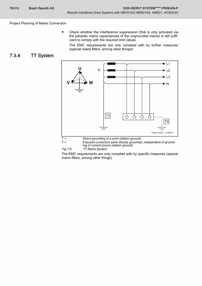
● Check whether the interference suppression (that is only activated viathe parasitic mains capacitances of the ungrounded mains) is still suffi‐cient to comply with the required limit valuesThe EMC requirements are only complied with by further measures(special mains filters, among other things)!
7.3.4 TT System
T = Direct grounding of a point (station ground)T = Exposed conductive parts directly grounded, independent of ground‐
ing of current source (station ground)Fig.7-5: TT Mains SystemThe EMC requirements are only complied with by specific measures (specialmains filters, among other things).
Bosch Rexroth AG DOK-INDRV*-SYSTEM*****-PR06-EN-P Rexroth IndraDrive Drive Systems with HMV01/02 HMS01/02, HMD01, HCS02/03
78/309
Project Planning of Mains Connection

7.3.5 Mains Grounded via Outer Conductor (Corner-Grounded Delta Mains)
I = Isolation of all active parts from ground, connection of one phase‑ generally phase V - to ground or via an impedance RE
T = Exposed conductive parts directly grounded, independent of ground‐ing of current source (station ground)
Fig.7-6: Mains Grounded via Outer ConductorNotes on Project Planning The EMC requirements are only complied with by specific measures (special
mains filters, among other things).
Mains filters HNF01, NFD at mains grounded via outer conductorHNF01.1 or NFD03.1 mains filters are not suited for operation onmains grounded via outer conductor. Use isolating transformers.Allowed mains connection voltage: See technical data of the re‐spective device
7.4 Mains Short-Circuit Power and Mains Connected Load7.4.1 General Information
Apart from the mains connected load, observe the following corridor of themains short-circuit power for the mains connection:● Minimum required mains short-circuit power (mains connected load) for
interference-free operationThe smaller the mains short-circuit power, the greater the mains pollu‐tion due to the load current with harmonics on the supply voltage of thedevice. This can disturb both the device and other devices at the samemains node.Minimum mains short-circuit power is required to limit mains pollutionand to have sufficiently high voltage for realizing the drive performance.
● Maximum allowed mains short-circuit power (for device protection)The higher the mains short-circuit power, the greater the short-circuitcurrents occurring in the case of error.Use mains chokes to limit the short-circuit currents in the case of highmains short-circuit power Sk. .
DOK-INDRV*-SYSTEM*****-PR06-EN-P Rexroth IndraDrive Drive Systems with HMV01/02 HMS01/02, HMD01, HCS02/03
Bosch Rexroth AG 79/309
Project Planning of Mains Connection

Explanations on the short designations used: See chapter 15.2 "Calculations for the Mains Connection" on page 260
7.4.2 Mains Short-Circuit PowerDefinition of Mains Short-Circuit
PowerPower at nominal voltage UN between the phases and the maximum mainsshort-circuit current IK at the connection point:
Sk Short-circuit power of the mainsIk Short-circuit currentUN Mains voltageFig.7-7: Mains Short-Circuit Power
For the mains short circuit power of the point of supply, ask yourlocal power supply company.
Definition of Mains Short-CircuitCurrent
The mains short-circuit current IK results in the case of a short circuit at thepoint of power supply connection.
XK System impedanceUN Mains voltageFig.7-8: Mains Short-Circuit Current
UL requirement "maximum short-circuit current SCCR"In the scope of CSA/UL, devices with C-UL listing may only beoperated at mains nodes with a symmetrical short-circuit current smaller than the indicated value SCCR.For the SCCR value, see the technical data of the device.If necessary, use mains chokes to increase the system impe‐dance and reduce the short-circuit current.SCCR = IK
Mains Classes According to Short-Circuit Power
We basically distinguish mains classes graded according to mains short-cir‐cuit power and system impedance:
UN = 400 V UN = 480 V
Classification Sk Xk Lk Xk Lk
MVA mOhm μH mOhm μH
1Rigid mains
200 0,80 2,55 1,15 3,67
150 1,07 3,40 1,54 4,89
100 1,60 5,09 2,30 7,33
50 3,20 10,19 4,61 14,67
Bosch Rexroth AG DOK-INDRV*-SYSTEM*****-PR06-EN-P Rexroth IndraDrive Drive Systems with HMV01/02 HMS01/02, HMD01, HCS02/03
80/309
Project Planning of Mains Connection

UN = 400 V UN = 480 V
Classification Sk Xk Lk Xk Lk
MVA mOhm μH mOhm μH
2Semi-rigid mains
40 4,00 12,73 5,76 18,33
30 5,33 16,98 7,68 24,45
20 8,00 25,46 11,52 36,67
15 10,67 33,95 15,36 48,89
10 16,00 50,93 23,04 73,34
5 32,00 101,86 46,08 146,68
4 40,00 127,32 57,60 183,35
3Non-rigid mains
3 53,33 169,77 76,80 244,46
2 80,00 254,65 115,20 366,69
1 160,00 509,30 230,40 733,39
0,6 266,67 848,83 384,00 1222,31
Sk Short-circuit power of the mainsXK System impedanceLk Inductance of mains phaseTab.7-2: Mains Classified According to Mains Short Circuit Power and Mains
Internal Resistance
Minimum inductanceThe specified minimum inductances protect the drive controllers(especially the DC bus capacitors) during operation at mains withlow impedance and high mains short-circuit power.Use mains chokes at mains with Lk < Lmin.
Example:UN = 400 V; SK > 20 MVA; Lk = 25.46 μHData Lmin of drive controller in technical data: 40 μHLk < Lmin: Use of assigned mains choke is required.
7.4.3 Mains Connected LoadDefinition of Mains Connected
LoadThe drive system loads the mains with effective power and wattless power,both together make the so-called apparent power. At the mains connection,the apparent power of the drive system is the mains connected load.The mains connected load is calculated from the planned power in the DCbus PDC and the power factor (cosφ with sinusoidal mains current and TPFwith non-sinusoidal mains current):
SLN Mains connected load in VAPDC DC bus continuous power in WTPF Total Power Factor λFig.7-9: Calculating the Mains Connected Load
DOK-INDRV*-SYSTEM*****-PR06-EN-P Rexroth IndraDrive Drive Systems with HMV01/02 HMS01/02, HMD01, HCS02/03
Bosch Rexroth AG 81/309
Project Planning of Mains Connection
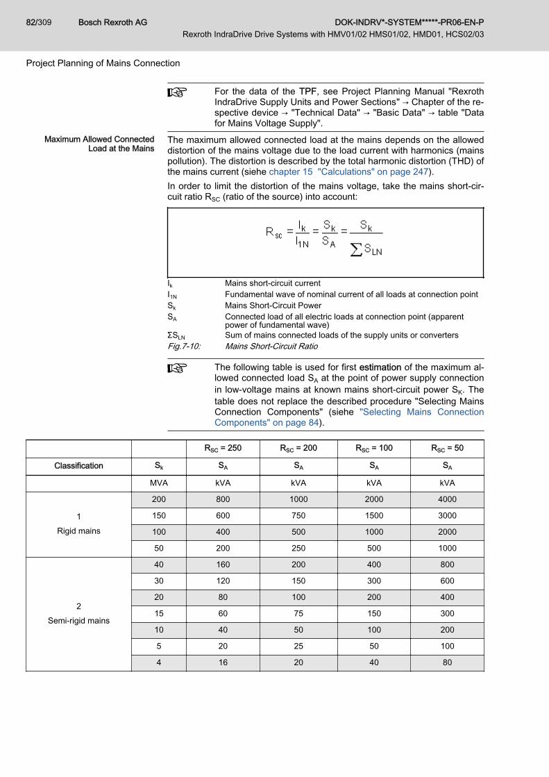
For the data of the TPF, see Project Planning Manual "RexrothIndraDrive Supply Units and Power Sections" → Chapter of the re‐spective device → "Technical Data" → "Basic Data" → table "Datafor Mains Voltage Supply".
Maximum Allowed ConnectedLoad at the Mains
The maximum allowed connected load at the mains depends on the alloweddistortion of the mains voltage due to the load current with harmonics (mainspollution). The distortion is described by the total harmonic distortion (THD) ofthe mains current (siehe chapter 15 "Calculations" on page 247).In order to limit the distortion of the mains voltage, take the mains short-cir‐cuit ratio RSC (ratio of the source) into account:
Ik Mains short-circuit currentI1N Fundamental wave of nominal current of all loads at connection pointSk Mains Short-Circuit PowerSA Connected load of all electric loads at connection point (apparent
power of fundamental wave)ΣSLN Sum of mains connected loads of the supply units or convertersFig.7-10: Mains Short-Circuit Ratio
The following table is used for first estimation of the maximum al‐lowed connected load SA at the point of power supply connectionin low-voltage mains at known mains short-circuit power SK. Thetable does not replace the described procedure "Selecting MainsConnection Components" (siehe "Selecting Mains ConnectionComponents" on page 84).
RSC = 250 RSC = 200 RSC = 100 RSC = 50
Classification Sk SA SA SA SA
MVA kVA kVA kVA kVA
1Rigid mains
200 800 1000 2000 4000
150 600 750 1500 3000
100 400 500 1000 2000
50 200 250 500 1000
2Semi-rigid mains
40 160 200 400 800
30 120 150 300 600
20 80 100 200 400
15 60 75 150 300
10 40 50 100 200
5 20 25 50 100
4 16 20 40 80
Bosch Rexroth AG DOK-INDRV*-SYSTEM*****-PR06-EN-P Rexroth IndraDrive Drive Systems with HMV01/02 HMS01/02, HMD01, HCS02/03
82/309
Project Planning of Mains Connection
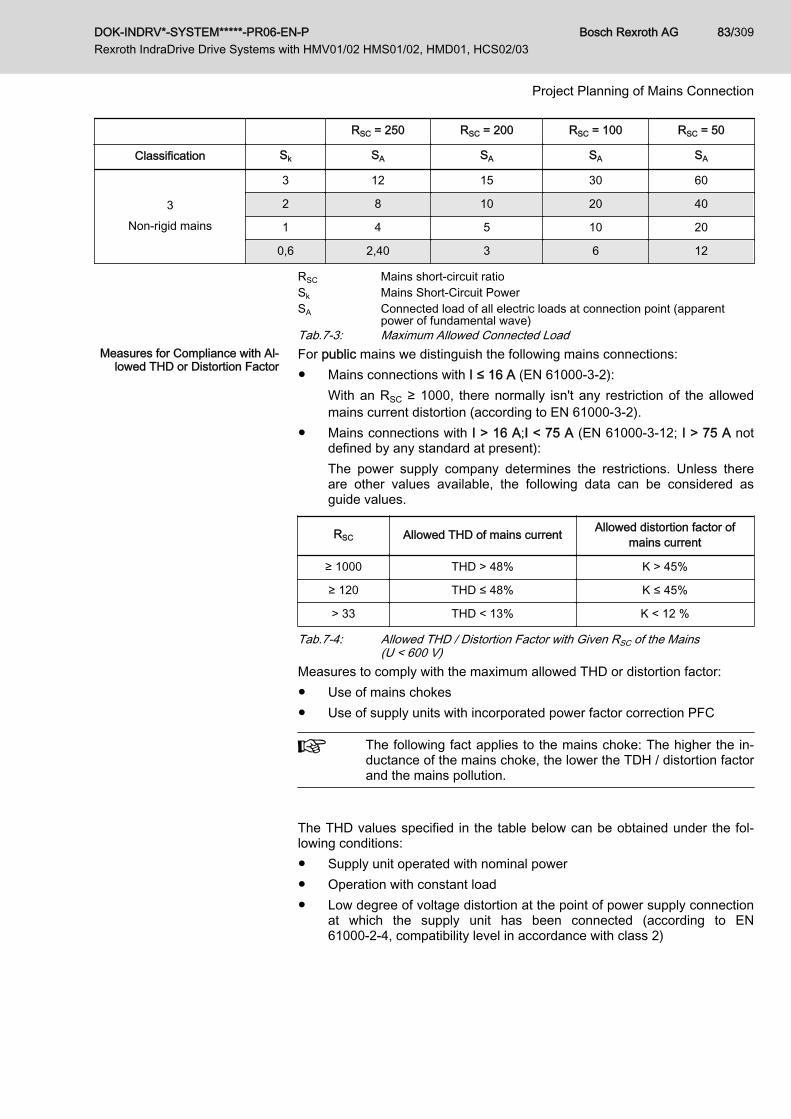
RSC = 250 RSC = 200 RSC = 100 RSC = 50
Classification Sk SA SA SA SA
3Non-rigid mains
3 12 15 30 60
2 8 10 20 40
1 4 5 10 20
0,6 2,40 3 6 12
RSC Mains short-circuit ratioSk Mains Short-Circuit PowerSA Connected load of all electric loads at connection point (apparent
power of fundamental wave)Tab.7-3: Maximum Allowed Connected Load
Measures for Compliance with Al‐lowed THD or Distortion Factor
For public mains we distinguish the following mains connections:● Mains connections with I ≤ 16 A (EN 61000-3-2):
With an RSC ≥ 1000, there normally isn't any restriction of the allowedmains current distortion (according to EN 61000-3-2).
● Mains connections with I > 16 A;I < 75 A (EN 61000-3-12; I > 75 A notdefined by any standard at present):The power supply company determines the restrictions. Unless thereare other values available, the following data can be considered asguide values.
RSC Allowed THD of mains current Allowed distortion factor ofmains current
≥ 1000 THD > 48% K > 45%
≥ 120 THD ≤ 48% K ≤ 45%
> 33 THD < 13% K < 12 %
Tab.7-4: Allowed THD / Distortion Factor with Given RSC of the Mains(U < 600 V)
Measures to comply with the maximum allowed THD or distortion factor:● Use of mains chokes● Use of supply units with incorporated power factor correction PFC
The following fact applies to the mains choke: The higher the in‐ductance of the mains choke, the lower the TDH / distortion factorand the mains pollution.
The THD values specified in the table below can be obtained under the fol‐lowing conditions:● Supply unit operated with nominal power● Operation with constant load● Low degree of voltage distortion at the point of power supply connection
at which the supply unit has been connected (according to EN61000-2-4, compatibility level in accordance with class 2)
DOK-INDRV*-SYSTEM*****-PR06-EN-P Rexroth IndraDrive Drive Systems with HMV01/02 HMS01/02, HMD01, HCS02/03
Bosch Rexroth AG 83/309
Project Planning of Mains Connection

Device type RealizableTHD of mains
current
Realizable dis‐tortion factor ofmains current
Supply unit or drive controllerwith and without mains choke
All devices THD ≥ 50% K ≥ 60% HMV01.1EHMV02.1EHCS03.1HCS02.1
Without
Devices withmains choke
THD < 48% K < 45% HMV01.1EHCS03.1HCS02.1
HNL01.1
Devices withPower FactorControl (PFC)
THD < 13% K < 12% HMV01.1RHMV02.1R
HNL01.1HNL02.1
Tab.7-5: Realizable THD / Distortion Factor for Drive Controllers
The allowed distortion factors can be achieved with the indicatedcombinations of drive controller and mains choke.
Observe the assignment of mains choke to drive controller inthe Project Planning Manual "Rexroth IndraDrive Supply Unitsand Power Sections" → Chapter of the respective device → "Tech‐nical Data" → "Basic Data" → table "Data for Mains Voltage Sup‐ply".
For detailed information on the emitted harmonics, see this Project PlanningManual in the chapter 15.2.3 Calculations for the Mains Harmonics, page261.
Selecting Mains Connection Com‐ponents
Procedure for selecting the required mains supply units and, if necessary,mains choke:1. Determine maximum current of mains connection at place of destination
of application.2. Determine mains short-circuit power Sk of mains at place of destination
of application (ask power supply company).3. Determine sum of connected loads SA.4. Determine ratio RSC.5. Read allowed THD or distortion factor K of mains current at place of
destination of application from table "Allowed THD...".6. Select appropriate mains supply unit and mains choke HNL from table
"Realizable THD...".
7.5 Protection Systems at the Mains Connection7.5.1 General Information
Protection against contact always depends on the kind and structure of thesupply mains and the mains conditions. For project planning of an installa‐tion, the typical behavior of the devices and supply mains should always betaken into account.For protection against contact (indirect contact) in a machine or plant in whicha drive system is used, the overcurrent protective device normally used isone with protective grounding according to IEC 364 and EN 50178 (Electron‐
Bosch Rexroth AG DOK-INDRV*-SYSTEM*****-PR06-EN-P Rexroth IndraDrive Drive Systems with HMV01/02 HMS01/02, HMD01, HCS02/03
84/309
Project Planning of Mains Connection

ic equipment for use in power installations). This is also specified in UL 508C(Industrial Control Equipment) for North America. Housing cover or encapsu‐lation by closed housing is used as protection against direct contact with liveconductors.
7.5.2 Protective GroundingGeneral Information
High contact voltage in case of error causedby too long disconnecting time of mains cir‐cuit breaker!
CAUTION
Select the mains circuit breaker such that the disconnecting time in the caseof error (short circuit or ground fault) is shorter than 5 s according toEN 60204‑1 (Annex A.1).Keep the fault loop impedance1) of the electrical equipment (machine, instal‐lation) as low as possible so that, in the case of error, the circuit breaker cantrigger within the specified disconnecting time.
Overcurrent protection normally is realized in the form of fuses or overcurrentrelease devices (circuit breakers, motor circuit breakers) installed at themains connection. For details see figure.Overcurrent protection generally is sized or set with a release current of1.3 × nominal current of the loads connected to this connection point.In the case of an insulation error or a connection between mains phase anddevice housing connected to the equipment grounding conductor, the drive isdisconnected from the mains.
For dimensioning the fuses, comply with these data: See chapter15.3.4 "Mains Contactor and Fusing " on page 265
1) Fault loop impedance is the cumulative impedance from the current source via theactive conductors to the fault location and back to the current source via the equip‐ment grounding conductor (see EN 60204‑1, Annex A.2). The fault loop impe‐dance must be determined either by means of calculation or by means of meas‐urement. Line lengths and the line cross sections have an influence on the faultloop impedance.
DOK-INDRV*-SYSTEM*****-PR06-EN-P Rexroth IndraDrive Drive Systems with HMV01/02 HMS01/02, HMD01, HCS02/03
Bosch Rexroth AG 85/309
Project Planning of Mains Connection
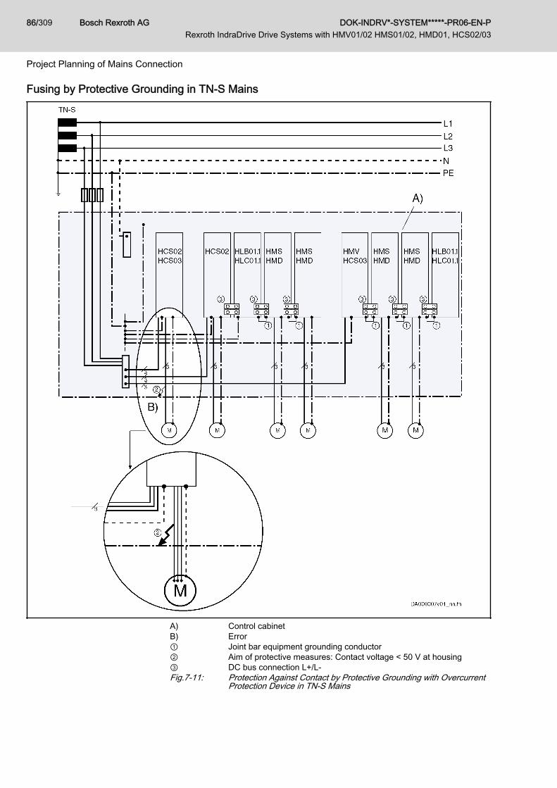
Fusing by Protective Grounding in TN-S Mains
A) Control cabinetB) Error① Joint bar equipment grounding conductor② Aim of protective measures: Contact voltage < 50 V at housing③ DC bus connection L+/L-Fig.7-11: Protection Against Contact by Protective Grounding with Overcurrent
Protection Device in TN-S Mains
Bosch Rexroth AG DOK-INDRV*-SYSTEM*****-PR06-EN-P Rexroth IndraDrive Drive Systems with HMV01/02 HMS01/02, HMD01, HCS02/03
86/309
Project Planning of Mains Connection
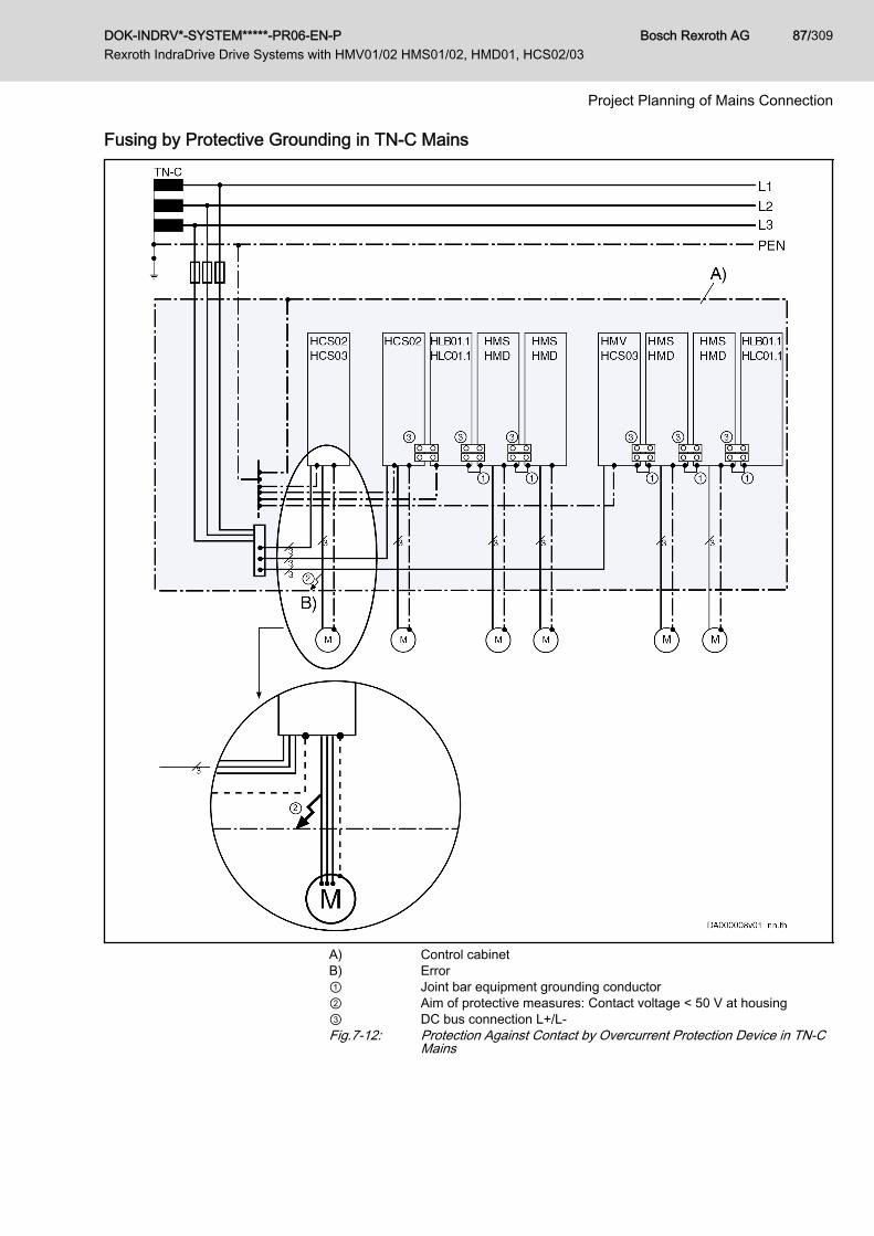
Fusing by Protective Grounding in TN-C Mains
A) Control cabinetB) Error① Joint bar equipment grounding conductor② Aim of protective measures: Contact voltage < 50 V at housing③ DC bus connection L+/L-Fig.7-12: Protection Against Contact by Overcurrent Protection Device in TN-C
Mains
DOK-INDRV*-SYSTEM*****-PR06-EN-P Rexroth IndraDrive Drive Systems with HMV01/02 HMS01/02, HMD01, HCS02/03
Bosch Rexroth AG 87/309
Project Planning of Mains Connection
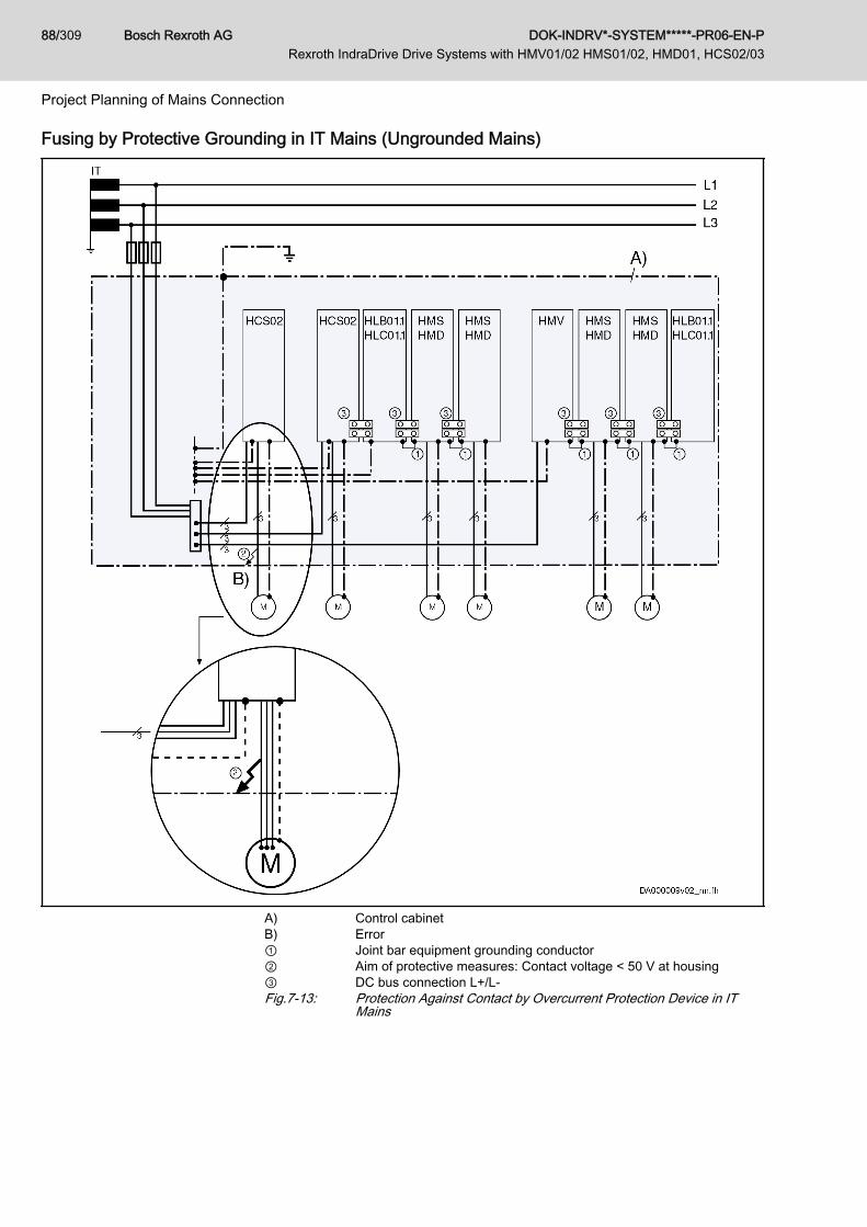
Fusing by Protective Grounding in IT Mains (Ungrounded Mains)
A) Control cabinetB) Error① Joint bar equipment grounding conductor② Aim of protective measures: Contact voltage < 50 V at housing③ DC bus connection L+/L-Fig.7-13: Protection Against Contact by Overcurrent Protection Device in IT
Mains
Bosch Rexroth AG DOK-INDRV*-SYSTEM*****-PR06-EN-P Rexroth IndraDrive Drive Systems with HMV01/02 HMS01/02, HMD01, HCS02/03
88/309
Project Planning of Mains Connection

7.5.3 Connection for the Equipment Grounding ConductorGeneral Information
Lethal electric shock when touching the hous‐ing caused by faulty connection of equipmentgrounding conductor!
WARNING
Observe the mentioned notes on installation in any case, in order to excludedanger by electric shock when touching the housing, even in case an equip‐ment grounding conductor connection is broken.
Equipment Grounding Connection Between the ComponentsObserve the notes on installation.Siehe chapter 13.1.4 "Connection Point of Equipment Grounding Conductorand Equipment Grounding Connections" on page 223).
Connecting Equipment Grounding Conductor to MainsAccording to the standards "Electronic equipment for use in power installa‐tions" (EN50178, chapter 5.3.2.1) and "Adjustable speed electrical powerdrive systems" (EN 61800-5-1, chapter 4.2.5.4.2), a stationary connection ofthe equipment grounding conductor is required and one or more of the follow‐ing requirements have to be complied with:● Cross section of equipment grounding conductor at least 10 mm (rea‐
son: sufficient mechanical stability required)● Mains and current supply automatically cut off when equipment ground‐
ing conductor interrupted (case of error)● Routing of a second equipment grounding conductor, via separate ter‐
minal connectors, with the same cross section as the first equipmentgrounding conductor. Mounting of an additional terminal connector forthis equipment grounding conductor.
7.5.4 Residual-Current-Operated Circuit Breakers (RCD, RCCB) as Addi‐tional Fusing
General InformationThe following designations are used for residual-current-operated circuitbreakers:● RCCB (Residual-Current-Operated Circuit Breaker)● RCD (Residual-Current-Operated Device)● RCM (Residual-Current Monitoring Device)● Earth-leakage circuit breaker (voltage-independent)● Residual-current circuit breaker (voltage-dependent)
It is only to a limited extent that residual-current-operated circuitbreakers can be used with Rexroth IndraDrive systems.
If these circuit breakers are to be used, the company erecting the installationhas to check the mutual compatibility of the residual-current-operated circuitbreakers and installation or machine with the drive system, in order to avoidaccidental triggering of the residual-current-operated circuit breaker. This hasto be taken into account
DOK-INDRV*-SYSTEM*****-PR06-EN-P Rexroth IndraDrive Drive Systems with HMV01/02 HMS01/02, HMD01, HCS02/03
Bosch Rexroth AG 89/309
Project Planning of Mains Connection
● for switch-on processes, due to high asymmetric inrush currents and● during operation of the installation, due to leakage currents produced in
normal operation.
Cause of Leakage CurrentsFor the purpose of stepless speed variation with a high degree of positioningaccuracy and dynamic response, certain modulation procedures are neces‐sary for drive systems. For physical reasons, these modulation proceduresgive rise to inevitable leakage current produced during normal operation. Es‐pecially with unbalanced loads of the mains phases or a large number ofdrives it can easily reach some amperes (rms value).The leakage current is not sinusoidal but pulse-shaped. For this reason,measuring instruments normally sized for alternating currents in the range of50 Hz are not suited. Use measuring instruments with rms value measuringranges up to at least 150 kHz.The degree of leakage current depends on the following features of the in‐stallation:● Kind of inrush current limitation● Number, kind and size drives used● Length and cross section of connected motor power cables● Grounding conditions of the mains at the site of installation● Unbalance of the three-phase system● Kind of filters and chokes connected in the incoming circuit● EMC measures that are takenIf measures are taken to improve the electromagnetic compatibility (EMC) ofthe installation (mains filters, shielded lines), the leakage current in theground wire is inevitably increased, especially when switching on or in thecase of mains unbalance. Given these operating conditions, residual-current-operated circuit breakers can trigger without an error having occurred.The EMC measures are mainly based on capacitive short-circuiting of the in‐terference currents within the drive system. Inductive filter measures can re‐duce the leakage currents, but affect the dynamic response of the drive andbring about● higher construction volume● higher weight● expensive core material
Possibilities of UseMotor Cable Length Keep the motor cables as short as possible. Only short motor cables do allow
low leakage currents and thereby enable residual-current-operated circuitbreakers to work.
Kinds of Residual-Current-Operat‐ed Circuit Breakers
There are two kinds of residual-current-operated circuit breakers:1. Residual-current-operated circuit breakers sensitive to power pulse cur‐
rent (type A acc. to IEC 60755)These are normally used. However, it is only pulsating direct fault cur‐rents of a maximum of 5 mA and sinusoidal alternating fault currentsthat they switch off safely. This is why they are not allowed for devicesthat can generate smoothed direct fault currents. In the case of smooth‐ed direct fault currents that can be produced in power supply units,mains rectifiers and drive controllers with power converters in B6 circuit,
Bosch Rexroth AG DOK-INDRV*-SYSTEM*****-PR06-EN-P Rexroth IndraDrive Drive Systems with HMV01/02 HMS01/02, HMD01, HCS02/03
90/309
Project Planning of Mains Connection

the residual-current-operated circuit breaker is not triggered. This blocksthe triggering of a residual-current-operated circuit breaker sensitive topower pulse current in the case of ground contact, i.e. in the case oferror.Residual-current-operated circuit breakers sensitive to power pulse cur‐rent do not provide any protection against inadmissible contact voltage.
2. Residual-current-operated circuit breakers sensitive to universal current(type B acc. to IEC 60755)These circuit breakers are suited for smoothed direct fault currents, too,and safely switch off devices with B6 input rectifiers.When a current with 30 mA triggers the residual-current-operated circuitbreaker, it is possible to use a residual-current-operated circuit breakerwith higher tripping current for machine protection.If this residual-current-operated circuit breaker triggers accidentally, too,check in how far the above conditions and dependencies can be im‐proved (for example, by connecting current-compensated mains chokesin the incoming circuit, increasing the inrush current limitation).
Using Isolating Transformer to Re‐duce Leakage Current in Mains
If there is no improvement achieved and the residual-current-operated circuitbreaker, due to specific mains conditions on site, has to be used neverthe‐less on the mains input side, connect an isolating transformer between mainsconnection and power connection of the drive system. This reduces the leak‐age current in the ground wire of the mains that is produced during normaloperation which allows using the residual-current-operated circuit breaker.Connect the neutral point of the secondary winding of the isolating transform‐er to the equipment grounding conductor of the drive system.Adjust the ground-fault loop impedance to the overcurrent protective deviceso that the unit can be switched off in the case of failure.Before operating enable, check the correct function of the overcurrent protec‐tion device including activation in the case of failure.Exclusive fusing by residual-current-operated circuit breakerFor drive systems with electronic drive controllers, exclusive protection bymeans of a residual-current-operated circuit breaker normally is not possibleand not allowed.Electronic equipment that has a nominal power higher than 4 kVA or is des‐tined for permanent connection does not need residual-current-operated cir‐cuit breakers.According to IEC 364 and EN 50178, the supply-side protection against con‐tact for indirect contact, i.e. in the case of insulation failure, has to be provi‐ded in a different way, for example by means of overcurrent protective de‐vice, protective grounding, protective-conductor system, protective separationor total insulation.
Using Residual-Current-Operated Circuit Breakers at HCS Drive ControllersHCS Drive Controllers at Residu‐
al-Current-Operated Circuit Break‐er
Residual-current-operated circuit breakers can be used under the followingconditions:● Residual-current-operated circuit breaker is of type B (IEC60755)● Trip limit of the residual-current circuit breaker is ≥ 300 mA● Supplying TN-S mains● Maximum length of motor cable 20 m in shielded design● Use of an HNF01 or NFD03 mains filter
DOK-INDRV*-SYSTEM*****-PR06-EN-P Rexroth IndraDrive Drive Systems with HMV01/02 HMS01/02, HMD01, HCS02/03
Bosch Rexroth AG 91/309
Project Planning of Mains Connection
● Each residual-current-operated circuit breaker only supplies one drivecontroller
● Only Rexroth components and accessories including cables and filtersare used
Using Residual-Current-Operated Circuit Breakers at HMV Supply UnitsHMV01.1R, HMV02.1R at Residu‐al-Current-Operated Circuit Break‐
er
Due to their function, regenerative HMV0x.1R supply units are unsuitable forthe use of residual-current-operated circuit breakers.
7.5.5 Insulation Monitoring DevicesInsulation monitoring devices are normally used in IT mains with insulatedneutral point. The aim is to have a monitor triggered in the case of groundfault – which means in the case of error – without having to switch off theelectrical equipment.When the monitor signals an error, the ground fault is detected and removedwithout operation being interrupted. Switch-off only takes place if a secondground fault occurs before the first one has been removed.As insulation monitoring devices also measure the ground current at themains input of the building, too high leakage current can cause accidentalfalse triggering.There are the same notes on application applying as mentioned in the previ‐ous chapter 7.5 Protection Systems at the Mains Connection, page 84.
Bosch Rexroth AG DOK-INDRV*-SYSTEM*****-PR06-EN-P Rexroth IndraDrive Drive Systems with HMV01/02 HMS01/02, HMD01, HCS02/03
92/309
Project Planning of Mains Connection
8 Configuring the Drive System8.1 General Information
Within the Rexroth IndraDrive product range, it is possible to combine com‐ponents of the following subranges:● Rexroth IndraDrive C● Rexroth IndraDrive M● Rexroth IndraDrive MiYou have to select:Type of supply● Supply units● Converter● Type of mains connection
Additional component mains filterOther additional components for mains connection
Drive● Motors with measuring systems● Power sections● Control sections with options● Firmware for selected power sections with control sectionAdditional Components● For the DC bus● For the motor outputCables● For power supply to the motor● For signal evaluation from motor to control electronics
8.2 Type of Supply for Power Sections8.2.1 General Information
The requirements to the individual axes are known from the drive task andthe appropriate drive controllers - the drive system - have been selected forthis purpose. For this drive system, select the appropriate supply. The follow‐ing list will be explained in detail in this chapter:● Supply by HMV supply unit
– In central supply– In parallel operation
● Supply by HCS converter– In central supply– In parallel operation
● Supply by third-party supply units– RD500 - SFT converter
DOK-INDRV*-SYSTEM*****-PR06-EN-P Rexroth IndraDrive Drive Systems with HMV01/02 HMS01/02, HMD01, HCS02/03
Bosch Rexroth AG 93/309
Configuring the Drive System
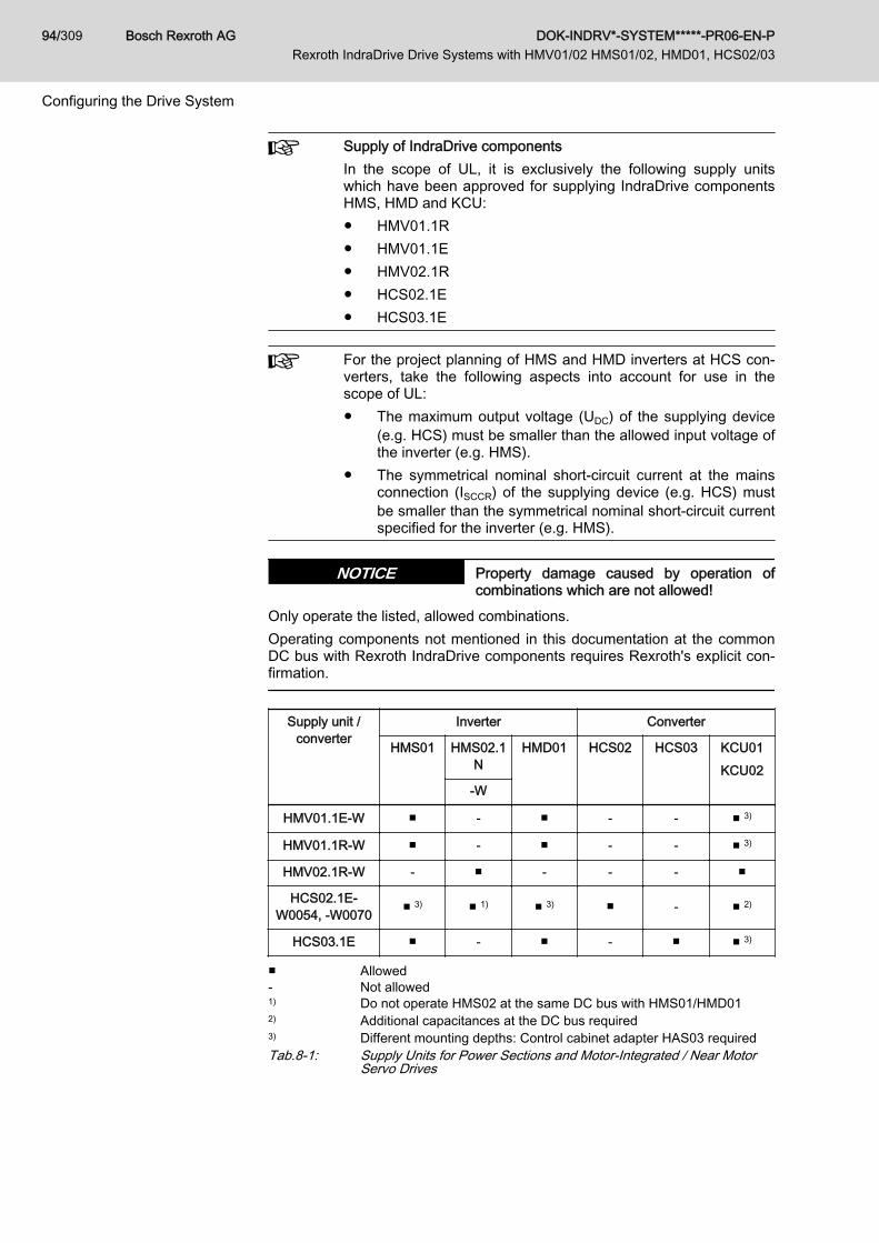
Supply of IndraDrive componentsIn the scope of UL, it is exclusively the following supply unitswhich have been approved for supplying IndraDrive componentsHMS, HMD and KCU:● HMV01.1R● HMV01.1E● HMV02.1R● HCS02.1E● HCS03.1E
For the project planning of HMS and HMD inverters at HCS con‐verters, take the following aspects into account for use in thescope of UL:● The maximum output voltage (UDC) of the supplying device
(e.g. HCS) must be smaller than the allowed input voltage ofthe inverter (e.g. HMS).
● The symmetrical nominal short-circuit current at the mainsconnection (ISCCR) of the supplying device (e.g. HCS) mustbe smaller than the symmetrical nominal short-circuit currentspecified for the inverter (e.g. HMS).
Property damage caused by operation ofcombinations which are not allowed!
NOTICE
Only operate the listed, allowed combinations.Operating components not mentioned in this documentation at the commonDC bus with Rexroth IndraDrive components requires Rexroth's explicit con‐firmation.
Supply unit /converter
Inverter Converter
HMS01 HMS02.1N
HMD01 HCS02 HCS03 KCU01KCU02
-W
HMV01.1E-W ■ - ■ - - ■ 3)
HMV01.1R-W ■ - ■ - - ■ 3)
HMV02.1R-W - ■ - - - ■
HCS02.1E-W0054, ‑W0070 ■ 3) ■ 1) ■ 3) ■ - ■ 2)
HCS03.1E ■ - ■ - ■ ■ 3)
■ Allowed- Not allowed1) Do not operate HMS02 at the same DC bus with HMS01/HMD012) Additional capacitances at the DC bus required3) Different mounting depths: Control cabinet adapter HAS03 requiredTab.8-1: Supply Units for Power Sections and Motor-Integrated / Near Motor
Servo Drives
Bosch Rexroth AG DOK-INDRV*-SYSTEM*****-PR06-EN-P Rexroth IndraDrive Drive Systems with HMV01/02 HMS01/02, HMD01, HCS02/03
94/309
Configuring the Drive System

KCU at HMV and HCS - number of axes, capacitances Cy
The drive connection box KCU passes the DC bus voltage of thesupply unit to the KSM/KMS via the hybrid cable. Due to decou‐pling components, KCU with the maximum number of KSM/KMSacts like one more axis with higher CY (capacitance againstground) for HMV01.1E, HMV02.1E supply units and HCS convert‐ers.When selecting the supply unit or converter, observe the allowedcombinations of HNF/NFD mains filter and HNL mains choke.See chapter 8.3 "Mains Connection Supply Units and Convert‐ers" on page 106
Notes on Project Planning forNumber of Axes, Cy
Converters and supply units can supply inverters at their DC buses.Detailed combinations of HCS converter, mains filter, mains choke:See chapter 8.3.3 "Mains Connection for HCS Converters" on page 113Detailed combinations of HMV supply unit, mains filter, mains choke:See chapter 8.3.2 "Mains Connection of HMV Supply Units" on page 109In the tables, observe the value Cy (capacitance against housing) in the "Ex‐planation" column. This value limits the number of inverters (number of axes).Orientation Guide for Selecting the Type of Supply
HMV supply unit HCS converter
Criterion Central supplywith HMVxx.x
Parallel opera‐tion with
HMVxx.xE(not W0030)
Centralsupply
Paralleloperation
Number of axes = 1 ■ □ ■ -
Number of axes ≤ 6Cy ≤ 2 × 600 nF
■ □ ■ ■
Number of axes ≤ 18 withmains filter "F240"Cy ≤ 2 × 1225 nF
■ □ □ □
Number of axes ≤ 40 withmains filter "M900"Cy ≤ 2 × 2040 nF
■ ■ - -
High overload ratio ■ ■ □ □
Regenerative operation withgreat energy contents
■HMVxx.xR
□ □ □
DOK-INDRV*-SYSTEM*****-PR06-EN-P Rexroth IndraDrive Drive Systems with HMV01/02 HMS01/02, HMD01, HCS02/03
Bosch Rexroth AG 95/309
Configuring the Drive System

HMV supply unit HCS converter
Criterion Central supplywith HMVxx.x
Parallel opera‐tion with
HMVxx.xE(not W0030)
Centralsupply
Paralleloperation
High kinetic energies in thecase of mains failure
□Additionally use HLR braking resistors
Single-phase operation - -□
OnlyHCS02
-
■ Recommended□ Allowed- Not allowedTab.8-2: Orientation Guide
8.2.2 HMV Supply Units for HMS/HMD Power SectionsCentral Supply HMV
Brief DescriptionThe mains connection "central supply" (individual supply) is the standard typeof connection for HMV. The "central supply" is characterized by one mainsconnection (mains circuit breaker, mains transformer, mains filter, mainschoke) for the drive system. Other drive controllers and additional compo‐nents are connected to the supply unit.
Block Diagram
HMVxx.xE Components marked with gray background color: Optional, dependingon the application
HMVxx.xR Mains filter and mains choke; necessaryHMVxx.xR-W0120
Mains filter, mains choke, external mains contactor; necessary
Fig.8-1: Central Supply HMVThe "group supply without DC bus connection of the groups" has to be han‐dled like individual supply for HMV.
Bosch Rexroth AG DOK-INDRV*-SYSTEM*****-PR06-EN-P Rexroth IndraDrive Drive Systems with HMV01/02 HMS01/02, HMD01, HCS02/03
96/309
Configuring the Drive System

HMVxx.xE Components marked with gray background color: Optional, dependingon the application
HMVxx.xR Mains filter and mains choke: necessaryHMVxx.xR-W0120
Mains filter, mains choke, external mains contactor: necessary
Fig.8-2: Group Supply HMV Without DC bus Connection of the Groups
When dimensioning the fuses in the supply feeder and in branch‐es, make sure to provide protection against overcurrent and over‐load in the case of error.See chapter 15.3.5 "Dimensioning the Line Cross Sections andFuses " on page 266
Notes on Project Planning The maximum allowed number of devices at the common DC bus is limitedby the ability of HMV to charge capacitances against housing (Cy).Use more HMVs, if the determined capacitance Cy exceeds the maximum al‐lowed value.
Damage to the supply unit!NOTICEDo not exceed allowed peak and continuous powers in the DC bus.Comply with minimum value of mean phase control factor ā (see data of con‐tinuous power of supply unit in the technical data, calculation see chapter15 Calculations, page 247), in order to avoid overload of the integrated DCbus capacitors by wattless currents.High load due to wattless current is generated, when, for example, synchro‐nous motors permanently deliver high torque at low speed or asynchronousmotors are operated with high magnetization currents.In these cases of operation, use additional capacitances at the DC bus.
Smart Energy Mode Regenerative supply units of the HMV0x.1R-W0***-A-07-FNN2 design (Smart
Energy Mode) reduce current and power peaks on the mains side. The SmartEnergy Mode limits the maximum device current to the 1.1‑fold value of thenominal current.
DOK-INDRV*-SYSTEM*****-PR06-EN-P Rexroth IndraDrive Drive Systems with HMV01/02 HMS01/02, HMD01, HCS02/03
Bosch Rexroth AG 97/309
Configuring the Drive System

For the project planning of a drive system with Smart Energy Mode, there is aseparate documentation. Write an e‑mail to [email protected], ifyou need this documentation (Indrv_HMV0xR_Smart_Energy_Mode_xx.pdf).
Parallel Operation HMV - Group Supply with DC Bus Connection HMV01, HMV02Brief Description"Group supply with DC bus connection" increases the available regenerativepower, the continuous braking resistor and infeeding power in the commonDC bus of several drive controllers.This mains connection is mainly used to cover the power range above thebiggest modular supply unit.
Block Diagram
HMVxx.xE Components marked with gray background color: Optional, dependingon the application
HMVxx.xR Mains filter and mains choke: necessaryHMVxx.xR-W0120
Mains filter, mains choke, external mains contactor: necessary
Fig.8-3: Parallel Operation - Group Supply HMV With DC bus Connection
When dimensioning the fuses in the supply feeder and in branch‐es, make sure to provide protection against overcurrent and over‐load in the case of error.See chapter 15.3.5 "Dimensioning the Line Cross Sections andFuses " on page 266
Notes on Project Planning Parallel operation of regenerative supply units HMV0x.xR is notallowed!
Supply unit Supply units at DC bus
HMV01.1E-W0030 Two of the same type
HMV01.1E-W0075
HMV01.1E-W0120
Bosch Rexroth AG DOK-INDRV*-SYSTEM*****-PR06-EN-P Rexroth IndraDrive Drive Systems with HMV01/02 HMS01/02, HMD01, HCS02/03
98/309
Configuring the Drive System

Supply unit Supply units at DC bus
HMV01.1R Parallel connection is not allowed!
HMV02.1R
Tab.8-3: Parallel Operation HMVFor mains connection, observe the control circuit for the mains connection.Parallel operation of HMV01 supply units● is allowed with HMV01.1E supply units of the same type current● requires a mains choke for each supply unit (for current sharing)● does not increase the maximum allowed number of drive controllers or
axes when operated without mains filter● requires a control circuit master-slave; see chapter 9 Circuits for the
Mains Connection, page 141.For detailed information on derating and mounting, there is the specificationwith document number 109-1261-4102-** (available on request).
8.2.3 Converter HCS as Supply UnitGeneral Information
Converters are designed for operating a single drive (see also individual sup‐ply with HCS). In particular, the power supply with the capacitors in the DCbus and the mains supply have been dimensioned with regard to operationunder rated conditions of the converter. When HCS converters are used assupply units, the power of the converter (PDC_cont, PDC_peak) is available at theDC bus connection for its own motor output and for further drive controllers.Operating HCS converters as supply unit causes higher load of the capaci‐tors in the DC bus.Additional capacitors in the DC bus reduce the additional load by distributingthe current.
Damage to the converter!NOTICEOperation as supply unit additionally loads the converter. Observe the al‐lowed peak power and continuous power (PDC_cont, PDC_peak) of the converter.Operate additional capacitors CDC_ext at the DC bus and observe the notes onproject planning.
Central Supply - HCS Supply HCS or HMS/HMD Drive ControllersBrief DescriptionThe "central supply" via HCS converters is the mains supply with which theconverter supplies further drive controllers.
DOK-INDRV*-SYSTEM*****-PR06-EN-P Rexroth IndraDrive Drive Systems with HMV01/02 HMS01/02, HMD01, HCS02/03
Bosch Rexroth AG 99/309
Configuring the Drive System
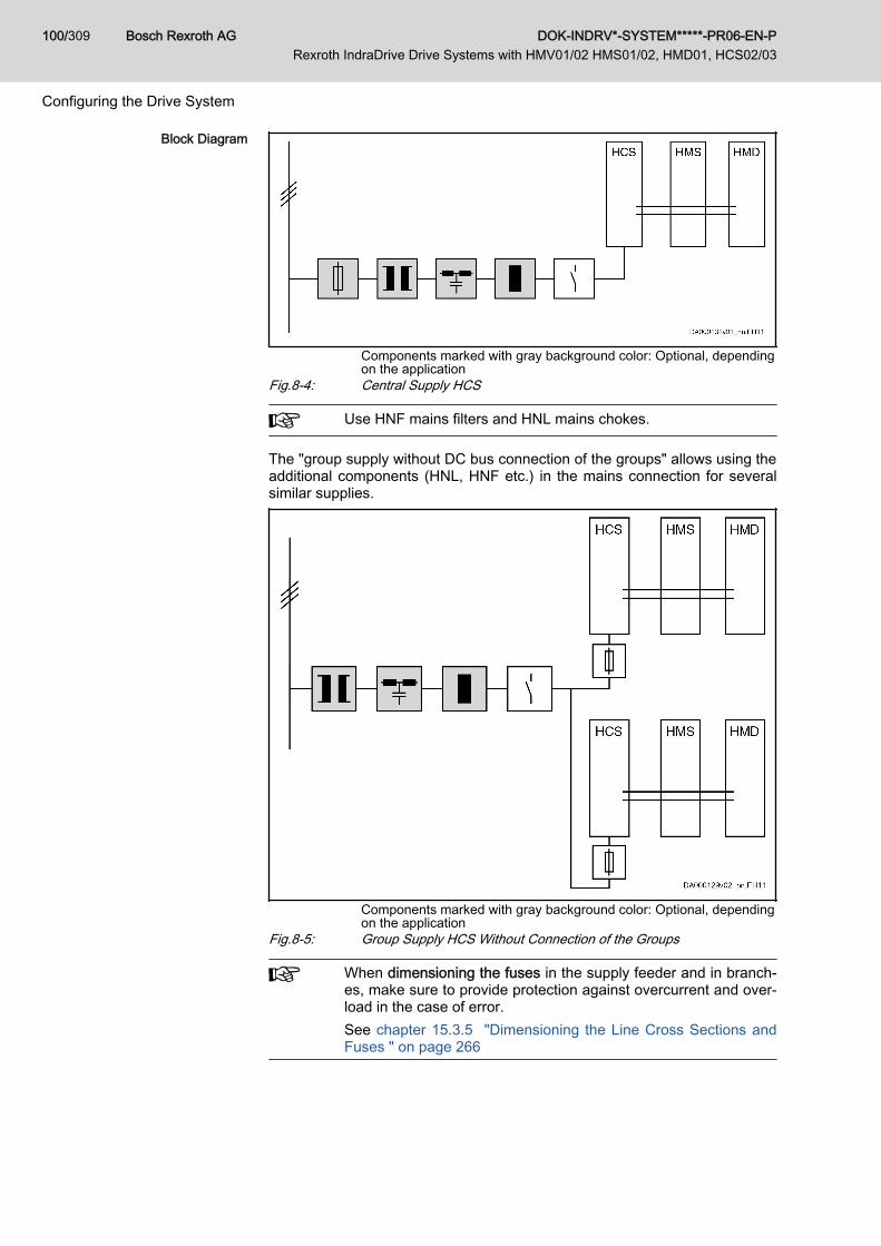
Block Diagram
Components marked with gray background color: Optional, dependingon the application
Fig.8-4: Central Supply HCS
Use HNF mains filters and HNL mains chokes.
The "group supply without DC bus connection of the groups" allows using theadditional components (HNL, HNF etc.) in the mains connection for severalsimilar supplies.
Components marked with gray background color: Optional, dependingon the application
Fig.8-5: Group Supply HCS Without Connection of the Groups
When dimensioning the fuses in the supply feeder and in branch‐es, make sure to provide protection against overcurrent and over‐load in the case of error.See chapter 15.3.5 "Dimensioning the Line Cross Sections andFuses " on page 266
Bosch Rexroth AG DOK-INDRV*-SYSTEM*****-PR06-EN-P Rexroth IndraDrive Drive Systems with HMV01/02 HMS01/02, HMD01, HCS02/03
100/309
Configuring the Drive System
Control the mains contactor in such a way (connect Bb contactsin series) that errors of both groups lead to circuit interruption!
Notes on Project Planning forHCS02 as Supply Unit for
HMS/HMD
The HCS02.1E-W0054 and -W0070 types are allowed as supply units.The HCS02.1E-W0012 and -W0028 types are not allowed.HCS02 converters as supply units for HMS/HMD require:● Accessory HAS03 (to adjust different mounting depths)● Accessory HAS04 (capacitances Cy at DC bus against ground)● Additional capacitors CDC_ext at the DC bus (external DC bus capaci‐
tance CDCext), if– the arithmetical mean of the output currents Iout is greater than
Iout_cont of the supplying device– the accumulated chronological sequences of the output currents
Iout and the DC bus power PDC (superposition of the individual loadprofiles) are greater than the allowed load profiles
Additional capacitance CDC_ext required for HCS02!To determine the additionally required capacitance CDC_ext, thefollowing guide values apply when using an HLC01.1 DC bus ca‐pacitor unit:● HMS01: Install 10 μF per A type current● HMD01: Install 20 μF per A type current● HMS02: No additional capacitance required
Arrangement of HCS02Place HCS02 to the left of HMS01, HMS02 or HMD01.Place the accessory HAS04 at the left of HCS02.Place the DC bus capacitor unit HLC01.1 at the junction fromHCS02 to HMS01, HMS02 or HMD01.
Notes on Project Planning With
HCS02 as Supply Unit for KCU02and KSM/KMS
The types HCS02.1E-W0054 and -W0070 are allowed as supply units forKCU02 and KSM02/KMS02.
Additional capacitance CDC_ext required for HCS02!For operation as supply unit with low load at the motor output(Pout ≤ 10 % × PDC_cont; Iout ≤ 10 % × Iout_cont, where Pout refers toKCU02/KSM02/KMS02 and PDC_cont to HCS02), the performancedata is available without additional capacitance CDC_ext at the DCbus.Use additional capacitors CDC_ext at the DC bus, when the load atthe motor output is higher.When you use the DC bus capacitor unit HLC01.1, the followingguide value applies when you determine the additional capaci‐tance CDC_ext:● 50 μF per kW of installed continuous power KSM/KMS, thus
700 μF for a KCU02 operated at rated power.
DOK-INDRV*-SYSTEM*****-PR06-EN-P Rexroth IndraDrive Drive Systems with HMV01/02 HMS01/02, HMD01, HCS02/03
Bosch Rexroth AG 101/309
Configuring the Drive System

Notes on Project Planning forHCS03
HCS03 converters as supply units for HMS01 / HMD01 require braking resis‐tors.
Operate HCS03 with HLR!To supply HMD01 and HMS01, operate HCS03 converters withbrake chopper (option -NNBV) and HLR braking resistor.
HCS03 with external capacitors in the DC busExternal capacitors in the DC bus (e.g. HLC) can only be operat‐ed at HCS03.1E-W0210.Thus, central supply with HCS03 is impossible.
Arrangement of HCS03Place HCS03 to the left of HMS01 and HMD01.Place the accessory HAS04 at the left of HCS03.
Notes on Commissioning When converters are operated as supply units for inverters or supplied as in‐verters from another converter, the drive controller must be parameterized forthis purpose.
For information on configuration and parameterization of the drive control‐lers, see Functional Description of firmware, chapter "Power Supply" and thepertinent parameters● P-0-0860, Converter configuration● P-0-0861, Power supply status word
Parallel Operation HCS - Group Supply with DC Bus Connection of the GroupsBrief Description"Group supply with DC bus connection" increases the available regenerativepower, the continuous braking resistor and infeeding power in the commonDC bus of several drive controllers or drive systems.
Bosch Rexroth AG DOK-INDRV*-SYSTEM*****-PR06-EN-P Rexroth IndraDrive Drive Systems with HMV01/02 HMS01/02, HMD01, HCS02/03
102/309
Configuring the Drive System

Block Diagram
Components marked with gray background color: Optional, dependingon the application
Fig.8-6: Parallel Operation HCSNotes on Project Planning Parallel operation is only allowed with drive controllers of the
same type current.
Mains contactorWhen using the component HCS03.1E with HNK01.1, connectthe mains contactor electrically before HNK and HCS03.Control mains contactors in such a way that error messages atthe converters connected in parallel can interrupt the power sup‐ply from the mains (e.g., connect Bb contacts of HCS in series).When controlling several mains contactors, additionally makesure that the mains contactors are always controlled simultane‐ously and synchronously so that each HCS only has to charge itsown DC bus capacitors when power voltage is switched on.
When dimensioning the fuses in the supply feeder and in branch‐es, make sure to provide protection against overcurrent and over‐load in the case of error.See chapter 15.3.5 "Dimensioning the Line Cross Sections andFuses " on page 266
DOK-INDRV*-SYSTEM*****-PR06-EN-P Rexroth IndraDrive Drive Systems with HMV01/02 HMS01/02, HMD01, HCS02/03
Bosch Rexroth AG 103/309
Configuring the Drive System
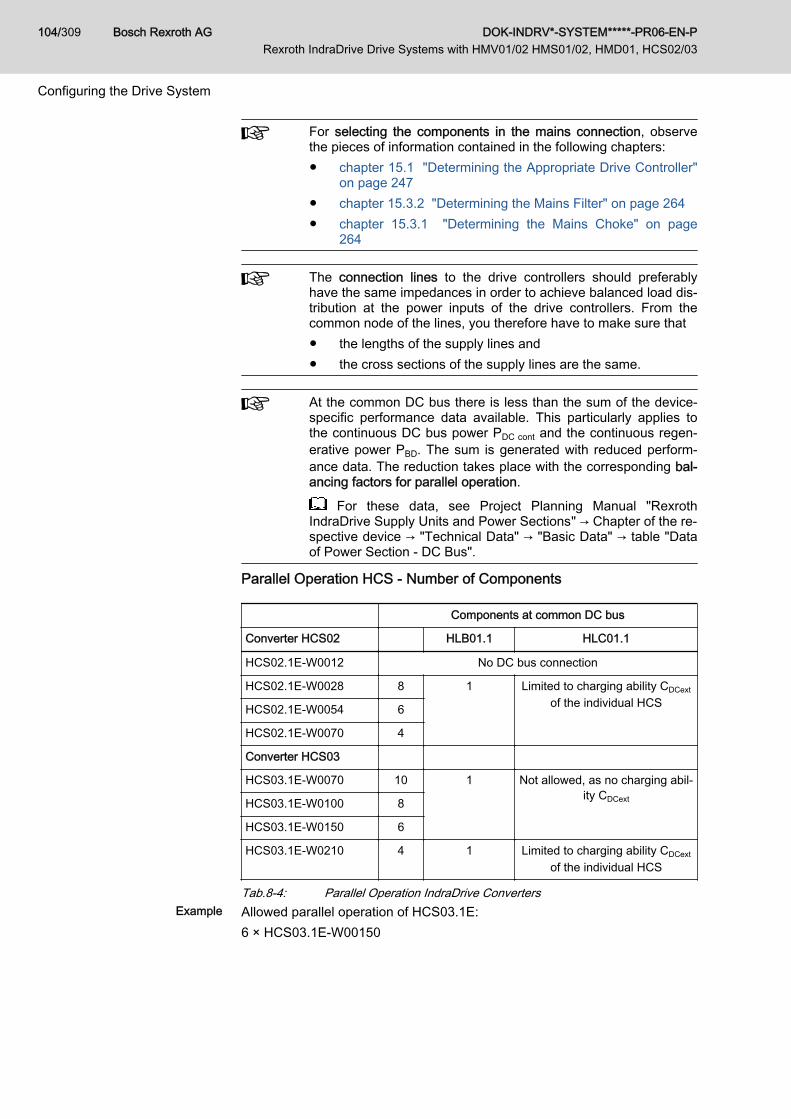
For selecting the components in the mains connection, observethe pieces of information contained in the following chapters:● chapter 15.1 "Determining the Appropriate Drive Controller"
on page 247● chapter 15.3.2 "Determining the Mains Filter" on page 264● chapter 15.3.1 "Determining the Mains Choke" on page
264
The connection lines to the drive controllers should preferablyhave the same impedances in order to achieve balanced load dis‐tribution at the power inputs of the drive controllers. From thecommon node of the lines, you therefore have to make sure that● the lengths of the supply lines and● the cross sections of the supply lines are the same.
At the common DC bus there is less than the sum of the device-specific performance data available. This particularly applies tothe continuous DC bus power PDC cont and the continuous regen‐erative power PBD. The sum is generated with reduced perform‐ance data. The reduction takes place with the corresponding bal‐ancing factors for parallel operation.
For these data, see Project Planning Manual "RexrothIndraDrive Supply Units and Power Sections" → Chapter of the re‐spective device → "Technical Data" → "Basic Data" → table "Dataof Power Section - DC Bus".
Parallel Operation HCS - Number of Components
Components at common DC bus
Converter HCS02 HLB01.1 HLC01.1
HCS02.1E-W0012 No DC bus connection
HCS02.1E-W0028 8 1 Limited to charging ability CDCext
of the individual HCSHCS02.1E-W0054 6
HCS02.1E-W0070 4
Converter HCS03
HCS03.1E-W0070 10 1 Not allowed, as no charging abil‐ity CDCextHCS03.1E-W0100 8
HCS03.1E-W0150 6
HCS03.1E-W0210 4 1 Limited to charging ability CDCext
of the individual HCS
Tab.8-4: Parallel Operation IndraDrive ConvertersExample Allowed parallel operation of HCS03.1E:
6 × HCS03.1E-W00150
Bosch Rexroth AG DOK-INDRV*-SYSTEM*****-PR06-EN-P Rexroth IndraDrive Drive Systems with HMV01/02 HMS01/02, HMD01, HCS02/03
104/309
Configuring the Drive System
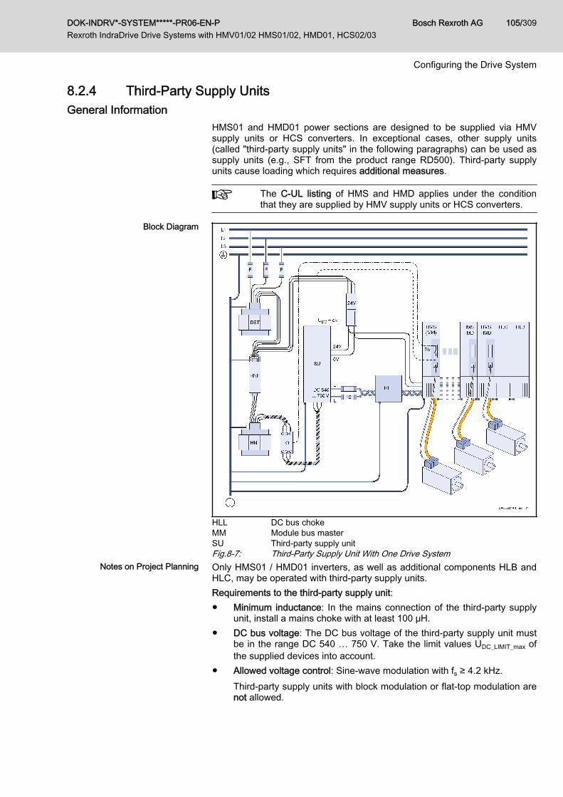
8.2.4 Third-Party Supply UnitsGeneral Information
HMS01 and HMD01 power sections are designed to be supplied via HMVsupply units or HCS converters. In exceptional cases, other supply units(called "third-party supply units" in the following paragraphs) can be used assupply units (e.g., SFT from the product range RD500). Third-party supplyunits cause loading which requires additional measures.
The C-UL listing of HMS and HMD applies under the conditionthat they are supplied by HMV supply units or HCS converters.
Block Diagram
HLL DC bus chokeMM Module bus masterSU Third-party supply unitFig.8-7: Third-Party Supply Unit With One Drive System
Notes on Project Planning Only HMS01 / HMD01 inverters, as well as additional components HLB andHLC, may be operated with third-party supply units.Requirements to the third-party supply unit:● Minimum inductance: In the mains connection of the third-party supply
unit, install a mains choke with at least 100 μH.● DC bus voltage: The DC bus voltage of the third-party supply unit must
be in the range DC 540 … 750 V. Take the limit values UDC_LIMIT_max ofthe supplied devices into account.
● Allowed voltage control: Sine-wave modulation with fs ≥ 4.2 kHz.Third-party supply units with block modulation or flat-top modulation arenot allowed.
DOK-INDRV*-SYSTEM*****-PR06-EN-P Rexroth IndraDrive Drive Systems with HMV01/02 HMS01/02, HMD01, HCS02/03
Bosch Rexroth AG 105/309
Configuring the Drive System

Requirements to the drive system:● DC bus choke: Per drive system, use one additional component
HLL01.1N for connection to the DC bus of the third-party supply unit.● DC bus current: Comply with maximum allowed DC bus current of
100 A.● Additional capacitances: Use at least 50 μFper kW of installed continu‐
ous power in the form of DC bus capacitor unit HLC01.● Leakage capacitance Cab: The leakage capacitance per drive system
(motors and motor cables) mustn't be more than a maximum of 500 nF.● Capacitances against housing CY: Per drive system, the capacitance
against housing mustn't exceed 2 × 850 nF (850 nF at L+, 850 nF at L-)and mustn't fall below 2 × 300 nF (300 nF at L+, 300 nF at L-).
● Peak voltage: Limit voltage L+ against and L- against to a maxi‐mum of 1 kV.
● If the drive system can be disconnected from the third-party supply unitin operation (e.g., in the case of overcurrent by fuses), use DC bus re‐sistor unit HLB01 with Wmax ≥ Wmax_installiert.
Notes on Commissioning Supply units, converters, inverters and additional components of the RexrothIndraDrive product range have a module bus X1. Via the module bus, infor‐mation on the status within the drive system is exchanged and the powersupply from the mains is influenced.Supply units of other product ranges have no module bus. With the drive firm‐ware as of version MPx‑04VRS, you can configure an inverter as module busmaster. Integrate the relay contact of the module bus master configured asBb contact in the control circuit of the power supply in such a way that thecircuit is interrupted when the relay contact opens.
For information on configuration and parameterization of the drive control‐lers, see Functional Description of firmware, chapter "Power Supply" and thepertinent parameters● P-0-0860, Converter configuration● P-0-0861, Power supply status wordTake the information on circuits for the mains connection into account (seechapter 9 "Circuits for the Mains Connection" on page 141).
8.3 Mains Connection Supply Units and Converters8.3.1 General Information
The mains connection consists of:● Protection against overload (e.g., fuses for line protection)
When dimensioning the fuses in the supply feeder and in branch‐es, make sure to provide protection against overcurrent and over‐load in the case of error.See chapter 15.3.5 "Dimensioning the Line Cross Sections andFuses " on page 266
● If necessary, an autotransformer or isolating transformer for voltage ad‐justment
● HNF mains filter
Bosch Rexroth AG DOK-INDRV*-SYSTEM*****-PR06-EN-P Rexroth IndraDrive Drive Systems with HMV01/02 HMS01/02, HMD01, HCS02/03
106/309
Configuring the Drive System
● HNL mains choke● If necessary, combination of mains filter and HNK mains choke● Mains contactor (integrated for some HMV)
Notes on Project Planning From the tables in the following chapters, select the mains connection for theprojected supply (HMV or HCS) and take the given values into account. Ifnecessary, split the drive system up or use a more powerful mains filter (e.g.,type "M900" instead of type "F240").● Cy (capacitance against housing)
This capacitance must be charged by the supply unit or converter whenthe mains voltage is switched on and is limited by the charging ability ofthe supply units and converters.In the technical data, you can find the value of Cy for each component atthe DC bus.The value Cy mustn't fall below the required minimum value to attenuateand avoid oscillation in the mains connection.
● Max. number of axesThe allowed number of axes is limited by the mains filter, because theleakage current generated by the drive system loads the mains filter.
● Max. leakage capacitance Cab_g
Due to the leakage capacitance (capacitance of cables and motor),leakage current, which loads the mains filter, is generated by the switch‐ing at the output of the inverter.In the column "EMC limit value class to be achieved", you can find, forthe selected mains connection (mains filter, mains choke), the leakagecapacitance with which the combination can comply with the respectiveEMC limit value class.
● Motor cable lengthThe length of the motor cable determines the leakage capacitance. Withthe switching frequency which has been set, the leakage current is gen‐erated due to the leakage capacitance. The specified values of the mo‐tor cable length (switching frequency fs) cause the same load and filtereffect at the mains filter and are to be understood as guide values.
DOK-INDRV*-SYSTEM*****-PR06-EN-P Rexroth IndraDrive Drive Systems with HMV01/02 HMS01/02, HMD01, HCS02/03
Bosch Rexroth AG 107/309
Configuring the Drive System
Property damage due to mains filter overload!NOTICE● Do not connect mains filters in series, as this can cause resonance ef‐
fects on current and voltage.● Comply with the specified limits of Cy (capacitances against housing),
maximum leakage capacitance Cab_g and maximum number of axes, be‐cause otherwise the mains filter can lose its effect and get damaged.
● Only operate expressly allowed components at mains filters.Do not operate any other components, such as additional power supplyunits and fans, at HNF mains filters.
With mains filters at compensation units, make sure there aren't any reso‐nance effects on current and voltage.Observe the allowed harmonic limit values (THD) of the filter components(see chapter 15.3.7 "Determining the Allowed Operating Data of Mains Fil‐ters" on page 273).Make sure that the nominal current of the mains contactor does not exceedthe nominal current of the mains filter.
Circuit for the mains connectionObserve the chapter 9 Circuits for the Mains Connection,page 141.
Mains filters HNF01, NFD at mains grounded via outer conductorHNF01.1 or NFD03.1 mains filters are not suited for operation onmains grounded via outer conductor.Observe the allowed mains connection voltage in the technicaldata of the respective component.Install an isolating transformer.
Performance data without mains chokeOperation without mains choke is only allowed for certain supplyunits and converters.Take into account that supply units and converters, when operat‐ed without mains choke, have reduced performance data in com‐parison to normal operation with mains choke.Performance data: See technical data of the respective compo‐nent
Bosch Rexroth AG DOK-INDRV*-SYSTEM*****-PR06-EN-P Rexroth IndraDrive Drive Systems with HMV01/02 HMS01/02, HMD01, HCS02/03
108/309
Configuring the Drive System

EMC limit values and mains filter selectionExplanation on the sizing criterion EMC limit value class:● See chapter 10.1.3 "Noise Emission of the Drive System"
on page 182● Calculation formulas for determining the allowed leakage ca‐
pacitances:See chapter 15.3.6 "Determining the Leakage Capacitance"on page 272
● The mains filters used have been specifically dimensionedfor Rexroth drive systems. For filters by other manufacturers,Rexroth cannot guarantee mains interference suppressionwith regard to allowed limit values.
● The indicated EMC limit values apply to grounded mains.Ungrounded mains require additional measures.
The selection tables do not contain all practical applications (e.g., use ofmains filters and mains chokes by several drive systems). For such cases,mains filters and mains choke can be selected, too:● See chapter 15.3.1 "Determining the Mains Choke" on page 264● See chapter 15.3.2 "Determining the Mains Filter" on page 264
8.3.2 Mains Connection of HMV Supply UnitsMains Connection of HMV Supply Units - Additional Components
Use HNL mains choke and HNF mains filterFor interference-free operation of supply units with regenerationback to the mains (HMVxx.xR), use appropriate HNL mainschokes and HNF mains filters in the mains connection.
Supply unit Transformer Mains filter Mains choke
DST(auto)
DLT (isolat‐ing)
HNF01.1*-****-R****
HNF01.1*-****-E****
HNS02.1
HNL01.1E;HNL01.1E-
****-S
HNL01.1R;HNL01.1R-
****-S
HNL 02.1
HMV01.1E-W ■ ■ - ■ - ■ - -
HMV01.1R-W ■ ■ ■ (!) - - - ■ (!) -
HMV02.1R-W ■ ■ - - ■ (!) - - ■ (!)
■ Allowed■ (!) Must be used- Not allowedTab.8-5: Additional Components Mains Connection
DOK-INDRV*-SYSTEM*****-PR06-EN-P Rexroth IndraDrive Drive Systems with HMV01/02 HMS01/02, HMD01, HCS02/03
Bosch Rexroth AG 109/309
Configuring the Drive System
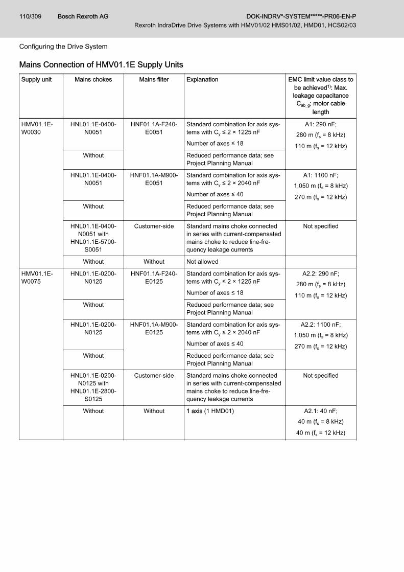
Mains Connection of HMV01.1E Supply UnitsSupply unit Mains chokes Mains filter Explanation EMC limit value class to
be achieved1): Max.leakage capacitance
Cab_g; motor cablelength
HMV01.1E-W0030
HNL01.1E-0400-N0051
HNF01.1A-F240-E0051
Standard combination for axis sys‐tems with Cy ≤ 2 × 1225 nF
Number of axes ≤ 18
A1: 290 nF;280 m (fs = 8 kHz)
110 m (fs = 12 kHz)Without Reduced performance data; see
Project Planning Manual
HNL01.1E-0400-N0051
HNF01.1A-M900-E0051
Standard combination for axis sys‐tems with Cy ≤ 2 × 2040 nF
Number of axes ≤ 40
A1: 1100 nF;1,050 m (fs = 8 kHz)
270 m (fs = 12 kHz)Without Reduced performance data; see
Project Planning Manual
HNL01.1E-0400-N0051 with
HNL01.1E-5700-S0051
Customer-side Standard mains choke connectedin series with current-compensatedmains choke to reduce line-fre‐quency leakage currents
Not specified
Without Without Not allowed
HMV01.1E-W0075
HNL01.1E-0200-N0125
HNF01.1A-F240-E0125
Standard combination for axis sys‐tems with Cy ≤ 2 × 1225 nF
Number of axes ≤ 18
A2.2: 290 nF;280 m (fs = 8 kHz)
110 m (fs = 12 kHz)Without Reduced performance data; see
Project Planning Manual
HNL01.1E-0200-N0125
HNF01.1A-M900-E0125
Standard combination for axis sys‐tems with Cy ≤ 2 × 2040 nF
Number of axes ≤ 40
A2.2: 1100 nF;1,050 m (fs = 8 kHz)
270 m (fs = 12 kHz)Without Reduced performance data; see
Project Planning Manual
HNL01.1E-0200-N0125 with
HNL01.1E-2800-S0125
Customer-side Standard mains choke connectedin series with current-compensatedmains choke to reduce line-fre‐quency leakage currents
Not specified
Without Without 1 axis (1 HMD01) A2.1: 40 nF;40 m (fs = 8 kHz)
40 m (fs = 12 kHz)
Bosch Rexroth AG DOK-INDRV*-SYSTEM*****-PR06-EN-P Rexroth IndraDrive Drive Systems with HMV01/02 HMS01/02, HMD01, HCS02/03
110/309
Configuring the Drive System

Supply unit Mains chokes Mains filter Explanation EMC limit value class tobe achieved1): Max.leakage capacitance
Cab_g; motor cablelength
HMV01.1E-W0120
HNL01.1E-0100-N0202
HNF01.1A-F240-E0202
Standard combination for axis sys‐tems with Cy ≤ 2 × 1225 nF
Number of axes ≤ 18
A2.2: 290 nF;280 m (fs = 8 kHz)
110 m (fs = 12 kHz)Without Reduced performance data; see
Project Planning Manual
HNL01.1E-0100-N0202
HNF01.1A-M900-E0202
Combination for axis systems withCy ≤ 2 × 2040 nF
Number of axes ≤ 40
A2.2: 1100 nF;1,050 m (fs = 8 kHz)
270 m (fs = 12 kHz)Without Reduced performance data; see
Project Planning Manual
HNL01.1E-0100-N0202 with
HNL01.1E-3400-S0202
Customer-side Standard mains choke connectedin series with current-compensatedmains choke to reduce line-fre‐quency leakage currents
Not specified
Without Without 1 axis (1 HMD01) A2.1: 40 nF;40 m (fs = 8 kHz)
40 m (fs = 12 kHz)
1) In grounded mainsTab.8-6: Selection of Mains Connection HMV01.1E
Mains Connection of HMV01.1R Supply UnitsSupply unit Mains chokes Mains filter Explanation EMC limit value class to
be achieved1): Max.leakage capacitance
Cab_g; motor cablelength
HMV01.1R-W0018
HNL01.1R-0980-C0026
HNF01.1A-F240-R0026
Standard combination for axis sys‐tems with Cy ≤ 2 × 1225 nF
Number of axes ≤ 18
A1: 290 nF;280 m (fs = 8 kHz)
110 m (fs = 12 kHz)
HNL01.1R-0980-C0026
HNF01.1A-M900-R0026
Standard combination for axis sys‐tems with Cy ≤ 2 × 2040 nF
Number of axes ≤ 40
A1: 1100 nF;1,050 m (fs = 8 kHz)
270 m (fs = 12 kHz)
HNL01.1R-0980-C0026 with
HNL01.1R-4200-S0026
Customer-side Standard mains choke connectedin series with current-compensatedmains choke to reduce line-fre‐quency leakage currents
n.s.
DOK-INDRV*-SYSTEM*****-PR06-EN-P Rexroth IndraDrive Drive Systems with HMV01/02 HMS01/02, HMD01, HCS02/03
Bosch Rexroth AG 111/309
Configuring the Drive System

Supply unit Mains chokes Mains filter Explanation EMC limit value class tobe achieved1): Max.leakage capacitance
Cab_g; motor cablelength
HMV01.1R-W0045
HNL01.1R-0590-C0065
HNF01.1A-F240-R0065
Standard combination for axis sys‐tems with Cy ≤ 2 × 1225 nF
Number of axes ≤ 18
A1: 290 nF;280 m (fs = 8 kHz)
110 m (fs = 12 kHz)
HNL01.1R-0590-C0065
HNF01.1A-M900-R0065
Standard combination for axis sys‐tems with Cy ≤ 2 × 2040 nF
Number of axes ≤ 40
A1: 1100 nF;1,050 m (fs = 8 kHz)
270 m (fs = 12 kHz)
HNL01.1R-0590-C0065 with
HNL01.1R-6300-S0065
Customer-side Standard mains choke connectedin series with current-compensatedmains choke to reduce line-fre‐quency leakage currents
n.s.
HMV01.1R-W0065
HNL01.1R-0540-C0094
HNF01.1A-F240-R0094
Standard combination for axis sys‐tems with Cy ≤ 2 × 1225 nF
Number of axes ≤ 18
A2.2: 290 nF;280 m (fs = 8 kHz)
110 m (fs = 12 kHz)
HNL01.1R-0540-C0094
HNF01.1A-M900-R0094
Standard combination for axis sys‐tems with Cy ≤ 2 × 2040 nF
Number of axes ≤ 40
A2.2: 1100 nF;1,050 m (fs = 8 kHz)
270 m (fs = 12 kHz)
HNL01.1R-0540-C0094 with
HNL01.1R-3000-S0094
Customer-side Standard mains choke connectedin series with current-compensatedmains choke to reduce line-fre‐quency leakage currents
n.s.
HMV01.1R-W0120
HNL01.1R-0300-C0180
HNF01.1A-H350-R0180
Standard combination for axis sys‐tems with Cy ≤ 2 × 10²⁰ nF
Number of axes ≤ 15
A2.2: 450 nF;350 m (fs = 8 kHz)
1) In grounded mainsTab.8-7: Selection of Mains Connection HMV01.1R
Mains Connection of HMV02.1R Supply UnitsSupply unit Mains choke Mains filter Explanation EMC limit value class to
be achieved1); motor ca‐ble length
HMV02.1R-W0015
HNL02.1R-0980-C0023
HNS02.1A-Q200-R0023
Standard combination for axis sys‐tems with Cy ≤ 2 × 1225 nF
Number of axes ≤ 12
A2.1;200 m (fs = 8 kHz)
1) In grounded mainsTab.8-8: Selection of Mains Connection HMV02.1R
Bosch Rexroth AG DOK-INDRV*-SYSTEM*****-PR06-EN-P Rexroth IndraDrive Drive Systems with HMV01/02 HMS01/02, HMD01, HCS02/03
112/309
Configuring the Drive System

Supply unit Mains choke Mains filter Explanation EMC limit val‐ue class to be
achieved1);motor cable
length
HMV02.1R-W0015
HNL02.1R-0980-C0023
HNS02.1A-Q200-R0023
Standard combination for axis systems withCy ≤ 12 × 200 nF
A2.1;200 m (fs = 8
kHz)
1) In grounded mainsTab.8-9: Mains Connection HMV02.1R
For the connections from the supply unit to the axis systems, ob‐serve the information contained in chapter chapter 13.1.6 "Con‐nection of the DC Bus Connections" on page 228.
8.3.3 Mains Connection for HCS ConvertersMains Connection for HCS Converters - Additional Components
Converter Transformer Mains filter Mains choke
DST (auto) DLT (isolat‐ing)
NFD03.1 HNF01.1*-****-R****
HNF01.1*-****-E****
HNK01.1 HNL01.1E;HNL01.1E-
****-S
HNL01.1R;HNL01.1R-
****-S
HCS02.1E ■ ■ ■ ■1) ■1) - ■ -
HCS03.1E ■ ■ ■ 2) ■1) ■1) ■ ■ -
■ Allowed- Not allowed1) Observe the note "Minimum value capacitance against ground at the
DC bus!"2) Maximum allowed motor cable length: 5 mTab.8-10: Additional Components in the Mains Connection of Converters
Minimum value capacitance against housing at the DC bus!When using HNF01.1 mains filters at HCS02.1 or HCS03.1, orwhen using HMS01, HMS02 or HMD01 at HCS02.1 or HCS03.1,make sure that at least 330 nF each take effect against ground atthe DC bus of the combined drive system at L+ and L-.Use the accessory HAS04, if the drive system falls below this ca‐pacitance value.
See Project Planning Manual "Rexroth IndraDrive SupplyUnits and Power Sections" → Chapter of the respective device →"Technical Data" → "Mechanical System and Mounting" → "Di‐mensions, Mass, Insulation, Sound Pressure Level"
Drive controller Capacitanceagainst housing
Cy1)
Use of HAS04 2) 3) required if …
HMS01.1N: < W0110 2 × 68 nF Number of HMS01 ≤ 3
HMS01.1N: ≥ W0110 2 × 100 nF Number of HMS01 ≤ 2
DOK-INDRV*-SYSTEM*****-PR06-EN-P Rexroth IndraDrive Drive Systems with HMV01/02 HMS01/02, HMD01, HCS02/03
Bosch Rexroth AG 113/309
Configuring the Drive System

Drive controller Capacitanceagainst housing
Cy1)
Use of HAS04 2) 3) required if …
HMS02 2 × 68 nF Number of HMS02 ≤ 3
HMD01 2 × 68 nF Number of HMD01 ≤ 3
HCS02 2 × 100 nF Number of HCS02 ≤ 2 4)
HCS03 2 × 100 nF Number of HCS03 ≤ 2 4)
KCU01 2 × 470 nF Not required
KCU02 2 × 100 nF
Accessory HAS04
HAS04.1-001 for HCS02 2 × 470 nF
HAS04.1-002 for HCS03 2 × 470 nF
1) See also Project Planning Manual "Rexroth IndraDrive Supply Unitsand Power Sections"
2) See Project Planning Manual "Rexroth IndraDrive Additional Compo‐nents and Accessories"
3) The number of drive controllers specified in this column already allowsfor the available capacitance (100 nF) of an HCS02 or HCS03 in thedrive system. Example of a drive system with HCS02 and HMS02:1 × HCS02 + 3 × HMS02 = 1 × 100 nF + 3 × 68 nF = 304 nF; 304 nF< 330 nF ⇒ HAS04 required; with 1 × HCS02 + 4 × HMS02, theHAS04 would not be required
4) HAS04 is only required, when an HNF01.1 mains filter is present inthe drive system
Tab.8-11: Cy, Capacitances against Housing
Mains Connection for HCS02 ConvertersConverter Mains chokes Mains filter Explanation EMC limit val‐
ue class to beachieved1):
Max. leakagecapacitance
Cab_g
HCS02.1E-W0012
HNL01.1E-1000-N0012 (optional)
NFD03.1-480-007 Standard combination for 1 converter A2.1
HNL01.1E-1000-N0020
NFD03.1-480-016 Group Supply● Type current HCS02 ≤ W0012● Motor cable length ≤ 120 m (fs = 8 kHz)
A2.2: 60 nFA1: 50 nFB1: 40 nF
HCS02.1E-W0028
HNL01.1E-1000-N0012 (optional)
NFD03.1-480-016 Standard combination for 1 converter A2.1
HNL01.1E-0600-N0032
NFD03.1-480-030 Group Supply● Type current HCS02 ≤ W0028● Motor cable length ≤ 120 m (fs = 8 kHz)
A2.2: 80 nFA1: 50 nF
Bosch Rexroth AG DOK-INDRV*-SYSTEM*****-PR06-EN-P Rexroth IndraDrive Drive Systems with HMV01/02 HMS01/02, HMD01, HCS02/03
114/309
Configuring the Drive System

Converter Mains chokes Mains filter Explanation EMC limit val‐ue class to be
achieved1):Max. leakagecapacitance
Cab_g
HCS02.1E-W0054
HNL01.1E-1000-N0020
NFD03.1-480-030 Standard combination for 1 converter A2.1
HNL01.1E-1000-N0020
NFD03.1-480-030 Central supply to axis systems● Type current HMS ≤ W0054● Type current HMD ≤ W0020● Type current HCS ≤ W0054● Sum of type currents ≤ 198
(without mains choke ≤ 120)● Cy ≤ 2 × 600 nF
● Motor cable length ≤ 120 m (fs = 8 kHz)
A2.2: 80 nFA1: 50 nF
HNL01.1E-1000-N0020
NFD03.1-480-055 A2.2: 110 nFA1: 70 nFB1: 55 nF
HNL01.1E-1000-N0020
HNF01.1A-F240-R0026
Central supply to axis systems● Type current HMS ≤ W0054● Type current HMD ≤ W0020● Type current HCS ≤ W0054● Sum of type currents ≤ 198
(without mains choke ≤ 120)● 2 × 330 nF ≤ Cy ≤ 2 × 1225 nF
● Motor cable length ≤ 240 m (fs = 8 kHz)
A2.2: 350 nFA1: 300 nFB1: 89 nF
HNL01.1E-1000-N0020
HNF01.1A-M900-R0026
Central supply to axis systems● Type current HMS ≤ W0054● Type current HMD ≤ W0020● Type current HCS ≤ W0054● Sum of type currents ≤ 198
(without mains choke ≤ 120)● 2 × 330 nF ≤ Cy ≤ 2 × 1225 nF
● Motor cable length ≤ 900 m (fs = 8 kHz)
A2.2: 350 nF
HNL01.1E-1000-N0020
HNF01.1A-M900-E0051
A2.2: 350 nFA1: 350 nFB1: 350 nF
DOK-INDRV*-SYSTEM*****-PR06-EN-P Rexroth IndraDrive Drive Systems with HMV01/02 HMS01/02, HMD01, HCS02/03
Bosch Rexroth AG 115/309
Configuring the Drive System

Converter Mains chokes Mains filter Explanation EMC limit val‐ue class to be
achieved1):Max. leakagecapacitance
Cab_g
HCS02.1E-W0070
HNL01.1E-0600-N0032
NFD03.1-480-055 Standard combination for 1 converter A2.1
HNL01.1E-0600-N0032
NFD03.1-480-055 Central supply to axis systems● Type current HMS ≤ W0054● Type current HMD ≤ W0036● Type current HCS ≤ W0070● Sum of type currents ≤ 270
(without mains choke ≤ 120)● Motor cable length ≤ 120 m (fs = 8 kHz)
A2.2: 100 nFA1: 70 nFB1: 52 nF
HNL01.1E-0600-N0032
NFD03.1-480-075 A2.2: 110 nFA1: 70 nFB1: 55 nF
HNL01.1E-0600-N0032
HNF01.1A-M900-E0051
Central supply to axis systems● Type current HMS ≤ W0054● Type current HMD ≤ W0036● Type current HCS ≤ W0070● Sum of type currents ≤ 270● 2 × 330 nF ≤ Cy
● Motor cable length ≤ 900 m (fs = 8 kHz)
A2.2: 350 nF
1) In grounded mainsTab.8-12: Selection of Mains Connection HCS02
Mains Connection for HCS03 Converters
With HCS03.1E drive controllers, the limit value class A2 (see"Limit Values for Line-Based Disturbances") can be achieved ingrounded mains when using the listed mains filters HNF01.1A orHNK01.1A or NFD03.1.Observe notes in chapter 11 Arranging the Components in theControl Cabinet , page 189.
Bosch Rexroth AG DOK-INDRV*-SYSTEM*****-PR06-EN-P Rexroth IndraDrive Drive Systems with HMV01/02 HMS01/02, HMD01, HCS02/03
116/309
Configuring the Drive System

Converter Mains chokes Mains filter Explanation
HCS03.1E-W0070
HNK01.1A-A075-E0050 Standard combination for 1 converterMotor cable length ≤ 75 m
HNL01.1E-0571-N0050
- Standard for operating one drive controller without mains filter
HNL01.1E-0571-N0050
NFD03.1-480-055 Combination for 1 converterMotor cable length ≤ 5 m
HNL01.1E-0571-N0050
HNF01.1A-F240-E0051
Central supply to axis systems● Type current HMS ≤ W0054● Type current HMD ≤ W0036● Sum of type currents ≤ 270● 2 × 330 nF ≤ Cy ≤ 2 × 600 nF
● Motor cable length ≤ 240 m (fs = 8 kHz)
HNL01.1E-0571-N0050
HNF01.1A-M900-E0051
Central supply to axis systems● Type current HMS ≤ W0054● Type current HMD ≤ W0036● Sum of type currents ≤ 270● 2 × 330 nF ≤ Cy ≤ 2 × 1225 nF
● Motor cable length ≤ 900 m (fs = 8 kHz)
HNL01.1E-0400-N0051 with
HNL01.1E-5700-S0051
Customer-side Standard mains choke connected in series with current-com‐pensated mains choke to reduce line-frequency leakage cur‐rents
DOK-INDRV*-SYSTEM*****-PR06-EN-P Rexroth IndraDrive Drive Systems with HMV01/02 HMS01/02, HMD01, HCS02/03
Bosch Rexroth AG 117/309
Configuring the Drive System
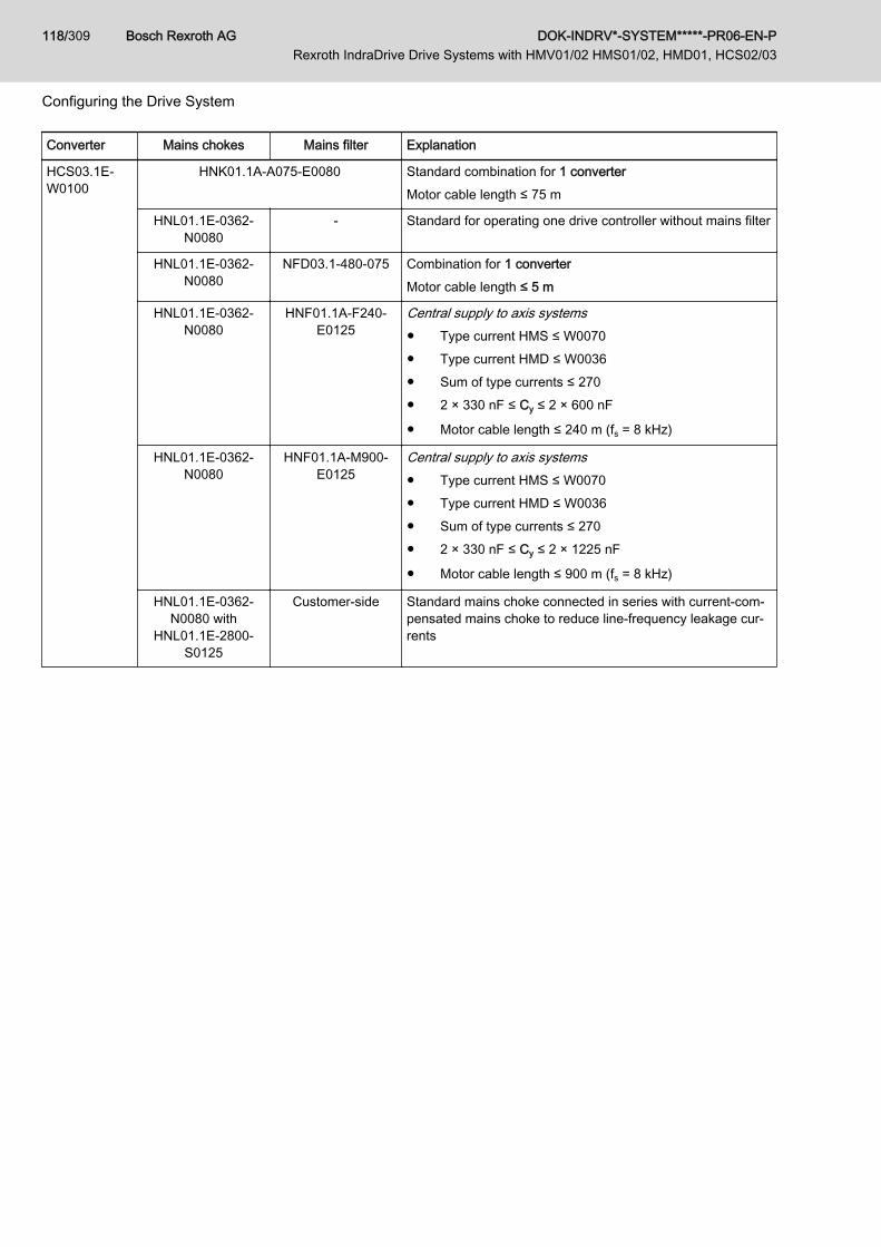
Converter Mains chokes Mains filter Explanation
HCS03.1E-W0100
HNK01.1A-A075-E0080 Standard combination for 1 converterMotor cable length ≤ 75 m
HNL01.1E-0362-N0080
- Standard for operating one drive controller without mains filter
HNL01.1E-0362-N0080
NFD03.1-480-075 Combination for 1 converterMotor cable length ≤ 5 m
HNL01.1E-0362-N0080
HNF01.1A-F240-E0125
Central supply to axis systems● Type current HMS ≤ W0070● Type current HMD ≤ W0036● Sum of type currents ≤ 270● 2 × 330 nF ≤ Cy ≤ 2 × 600 nF
● Motor cable length ≤ 240 m (fs = 8 kHz)
HNL01.1E-0362-N0080
HNF01.1A-M900-E0125
Central supply to axis systems● Type current HMS ≤ W0070● Type current HMD ≤ W0036● Sum of type currents ≤ 270● 2 × 330 nF ≤ Cy ≤ 2 × 1225 nF
● Motor cable length ≤ 900 m (fs = 8 kHz)
HNL01.1E-0362-N0080 with
HNL01.1E-2800-S0125
Customer-side Standard mains choke connected in series with current-com‐pensated mains choke to reduce line-frequency leakage cur‐rents
Bosch Rexroth AG DOK-INDRV*-SYSTEM*****-PR06-EN-P Rexroth IndraDrive Drive Systems with HMV01/02 HMS01/02, HMD01, HCS02/03
118/309
Configuring the Drive System

Converter Mains chokes Mains filter Explanation
HCS03.1E-W0150
HNK01.1A-A075-E0106 Standard combination for 1 converterMotor cable length ≤ 75 m
HNL01.1E-0240-N0106
- Standard for operating one drive controller without mains filter
HNL01.1E-0240-N0106
NFD03.1-480-130 Combination for 1 converterMotor cable length ≤ 5 m
HNL01.1E-0240-N0106
HNF01.1A-F240-E0125
Central supply to axis systems● Type current HMS ≤ W0070● Type current HMD ≤ W0036● Sum of type currents ≤ 270● 2 × 330 nF ≤ Cy ≤ 2 × 600 nF
● Motor cable length ≤ 240 m (fs = 8 kHz)
HNL01.1E-0240-N0106
HNF01.1A-M900-E0125
Central supply to axis systems● Type current HMS ≤ W0070● Type current HMD ≤ W0036● Sum of type currents ≤ 270● 2 × 330 nF ≤ Cy ≤ 2 × 1225 nF
● Motor cable length ≤ 900 m (fs = 8 kHz)
HNL01.1E-0240-N0106 with
HNL01.1E-2800-S0125
Customer-side Standard mains choke connected in series with current-com‐pensated mains choke to reduce line-frequency leakage cur‐rents
DOK-INDRV*-SYSTEM*****-PR06-EN-P Rexroth IndraDrive Drive Systems with HMV01/02 HMS01/02, HMD01, HCS02/03
Bosch Rexroth AG 119/309
Configuring the Drive System
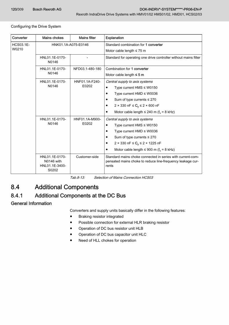
Converter Mains chokes Mains filter Explanation
HCS03.1E-W0210
HNK01.1A-A075-E0146 Standard combination for 1 converterMotor cable length ≤ 75 m
HNL01.1E-0170-N0146
- Standard for operating one drive controller without mains filter
HNL01.1E-0170-N0146
NFD03.1-480-180 Combination for 1 converterMotor cable length ≤ 5 m
HNL01.1E-0170-N0146
HNF01.1A-F240-E0202
Central supply to axis systems● Type current HMS ≤ W0150● Type current HMD ≤ W0036● Sum of type currents ≤ 270● 2 × 330 nF ≤ Cy ≤ 2 × 600 nF
● Motor cable length ≤ 240 m (fs = 8 kHz)
HNL01.1E-0170-N0146
HNF01.1A-M900-E0202
Central supply to axis systems● Type current HMS ≤ W0150● Type current HMD ≤ W0036● Sum of type currents ≤ 270● 2 × 330 nF ≤ Cy ≤ 2 × 1225 nF
● Motor cable length ≤ 900 m (fs = 8 kHz)
HNL01.1E-0170-N0146 with
HNL01.1E-3400-S0202
Customer-side Standard mains choke connected in series with current-com‐pensated mains choke to reduce line-frequency leakage cur‐rents
Tab.8-13: Selection of Mains Connection HCS03
8.4 Additional Components8.4.1 Additional Components at the DC BusGeneral Information
Converters and supply units basically differ in the following features:● Braking resistor integrated● Possible connection for external HLR braking resistor● Operation of DC bus resistor unit HLB● Operation of DC bus capacitor unit HLC● Need of HLL chokes for operation
Bosch Rexroth AG DOK-INDRV*-SYSTEM*****-PR06-EN-P Rexroth IndraDrive Drive Systems with HMV01/02 HMS01/02, HMD01, HCS02/03
120/309
Configuring the Drive System

Take value CDCext into account when operating HLC01!Observe the different abilities which HMV supply units and HCSconverters have to charge external capacitances at the DC bus (L+, L-).Take the value CDCext into account which is contained in the tech‐nical data of the respective device.
See also Project Planning Manual "Rexroth IndraDrive SupplyUnits and Power Sections" → "HCS03 Power Sections" → "Techni‐cal Data" → "Basic Data" → Data of Power Section - DC busIn the HCS03 product series, it is only allowed to operate externalcapacitances at the DC bus for the HCS03.1E-W0210 type.
Allowed Combinations The table below shows which additional components are allowed at the DCbus of HMV supply units and HCS converters.
Project planning of HLCTake the charging ability CDC_ext of the used supply unit or con‐verter into account.
Supply unit or converter HLB01.1C HLB01.1D HLC01.1C HLC01.1D HLR01.1 HLL02.1
HMV01.1E-W - ■≤ 2
■2) ■ - -
HMV01.1R-W - ■2) ■ - -
HMV02.1R-W■
≤ 2- ■ - - -
HCS02.1 ■ ■2) ■ ■2) ■3) -
HCS03.1 ■2) ■ - ■1) ■4) -
■ Allowed■ (!) Must be used- Not allowed1) Only HCS03.1E-…-W02102) Different mounting depths: Control cabinet adapter HAS03 required3) HCS02.1E-W0054, -W0070 (standard equipment: braking transistor
integrated)4) HCS03.1E in optional design -xxBx (integrated braking transistor) re‐
quiredTab.8-14: Combinations With Additional Components
DOK-INDRV*-SYSTEM*****-PR06-EN-P Rexroth IndraDrive Drive Systems with HMV01/02 HMS01/02, HMD01, HCS02/03
Bosch Rexroth AG 121/309
Configuring the Drive System

HLR Braking Resistors and DC Bus Resistor Units HLB
High temperatures in the proximity of brakingresistors!
NOTICE
Mount the braking resistors to temperature-resistant mounting surfaces insuch a way that the air can freely enter and escape and heat does not accu‐mulate.Take the minimum distances dtop, dbot and dhor into account.Take into account that the temperatures in the range of the indicated mini‐mum distances can be above 250 °C.Leave sufficient distance to combustible objects and take into account thatbraking resistors dissipate a lot of heat.Make sure there is free cooling air supply at the bottom dbot and cooling airdischarge at the top dtop.The space must be able to discharge the energy converted by the braking re‐sistor.
Selection Aid for Additional Components HLR, HLB
Criterion DC bus resistor unit HLB Braking resistor HLR
Regenerative operation with great energy con‐tents, e.g.● Deceleration of great centrifugal masses
at centrifuges● Long braking processes for crane lifting
gears
□Take energy absorption capacity
and continuous power into account
■Type of construction N
Check use of HMVxx.xR
Kinetic energy is generated in control cabinetand can be dissipated
■ □Type of construction A
Kinetic energy cannot be dissipated in controlcabinet
- ■Type of construction N
Observe degree of protection
Quick discharge of DC bus required ■DC bus short circuit device
Observe the note "Risk of firecaused by the "sacrificing behavior"
of the ZKS stage!"
-
Deceleration of synchronous motors in the caseof error "mains failure"
■ -
Supply unit HMV01.1R-W0120 ■ -
Converter HCS02 selected ■ ■
Converter HCS03 selected ■ ■Option -xxBx required
■ Recommended□ Suited to a limited extent- Not allowedTab.8-15: Selection Aid
Bosch Rexroth AG DOK-INDRV*-SYSTEM*****-PR06-EN-P Rexroth IndraDrive Drive Systems with HMV01/02 HMS01/02, HMD01, HCS02/03
122/309
Configuring the Drive System

Risk of fire caused by the "sacrificing behav‐ior" of the ZKS stage!
NOTICE
The "ZKS" input activates the "DC bus short circuit" function, when the 24Vcontrol voltage has not been applied and when there isn't any current flowingto the input. This condition can occur in the following situations:● Failure of 24V control voltage● Wire break● Activation of serially connected contacts (e.g. axis limit switches)If the kinetic energy of the mechanical axis system regenerated when brakingis greater than the energy absorption capacity of HLB, the HLB device re‐mains active when braking via ZKS takes place, until it is thermally destroyed(sacrificing behavior). Risk of fire! In this case, braking via ZKS may onlycome into effect in the case of an emergency (e.g. activation of an axis limitswitch causes the mains supply to be cut off and simultaneously causes the24V supply of the ZKS input to be interrupted).Install a 24V UPS, if the "sacrificing behavior" of HLB is relevant to your drivesystem in the case of an emergency. This prevents the braking via ZKSwhich causes HLB to be destroyed due to the failure of the 24V control volt‐age. Braking via ZKS then will only take place in cases of emergency.
Required type dataTo select an appropriate HLR braking resistor, the following typedata of the application are required:● Peak regenerative power PRS, Anlage
(See chapter 15.1.7 "Peak Regenerative Power" on page257)
● Continuous regenerative power PRD, Anlage
(See chapter 15.1.6 "Continuous Regenerative Power" onpage 255)
● Regenerative power WR, Anlage
(See chapter 15.1.4 "Regenerative Power" on page 251)
HCS02, HCS03 with HLR01 and simultaneously HLB01● The continuous power of the selected HLR01 has to be at
least as high as the continuous power of the HLB used.● Due to differences in balance, the total continuous power is
lower than the sum of the individual continuous powers. Thebalancing factor of 0.8 is regarded as the guide value.
Function of integrated braking resistor in HCS02 for operationwith HLR01Braking resistors have been integrated in HCS02 drive control‐lers. When operating external HLR01 baking resistors, the inte‐grated braking resistors are not loaded.See also parameter● P-0-0859, Data of internal braking resistor● P-0-0860, Converter configuration
DOK-INDRV*-SYSTEM*****-PR06-EN-P Rexroth IndraDrive Drive Systems with HMV01/02 HMS01/02, HMD01, HCS02/03
Bosch Rexroth AG 123/309
Configuring the Drive System

Observe degree of protection!When mounted outdoor or at the outside of the control cabinet,observe the degree of protection IP20 of the braking resistor.Protect the devices against intrusion of water.
Protection against overload!The HCS drive controller monitors the external braking resistor bymeans of the firmware which calculates a thermal image of thecurrent braking power. When the limit values for the thermal im‐age are exceeded, the converter switches off with the error"F8820 Braking resistor overload" to protect the baking resistoragainst overload.● Exclusively operate the combinations of converter - braking
resistor type listed below.● At the drive controllers HCS02 and HCS03, parameterize
the performance data of the selected braking resistor in pa‐rameter "P‑0‑0858, Data of external braking resistor". Forthis purpose, from the technical data take the data on:– Resistance value– Braking resistor continuous power– Maximum regenerative power to be absorbed
● Activate the selected braking resistor by setting bit 8 = 1 inparameter "P-0-0860, Converter configuration".
Braking Resistors HLR01 for HCS02
Converter Braking resistor type1) Type of con‐struction 2)
Type
Dimensions 3)
HCS02.1E-W0054-A-03-xNNx HLR01.1N-01K8-N40R0-… N O7
HCS02.1E-W0054-A-03-xNNx HLR01.1N-03K8-N40R0-… N B1
HCS02.1E-W0070-A-03-xNNx HLR01.1N-02K4-N28R0-… N O8
HCS02.1E-W0070-A-03-xNNx HLR01.1N-05K5-N28R2-… N B2
1) Complete type with: A-007-NNNN2) A: Device mounting; N: Version for free assembly3) See Project Planning Manual "Rexroth IndraDrive Additional Compo‐
nents and Accessories", dimension tables HLRTab.8-16: Assignment Braking Resistors HLR ↔ HCS02Braking Resistors HLR01 for HCS03
Converter Braking resistor type Type of con‐struction 1)
Type
Dimensions 2)
HCS03.1E-W0070-A-05-xNBV HLR01.1N‑0300‑N17R5-A-007-NNNN
A See corresponding di‐mensional drawing
HCS03.1E-W0100-A-05-xNBV HLR01.1N‑0470‑N11R7-A-007-NNNN
HCS03.1E-W0150-A-05-xNBV HLR01.1N‑0780‑N07R0-A-007-NNNN
HCS03.1E-W0210-A-05-xNBV HLR01.1N‑1K08‑N05R0-A-007-NNNN
Bosch Rexroth AG DOK-INDRV*-SYSTEM*****-PR06-EN-P Rexroth IndraDrive Drive Systems with HMV01/02 HMS01/02, HMD01, HCS02/03
124/309
Configuring the Drive System
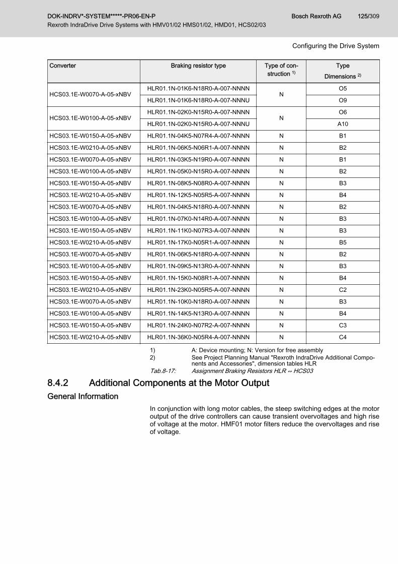
Converter Braking resistor type Type of con‐struction 1)
Type
Dimensions 2)
HCS03.1E-W0070-A-05-xNBVHLR01.1N-01K6-N18R0-A-007-NNNN
NO5
HLR01.1N-01K6-N18R0-A-007-NNNU O9
HCS03.1E-W0100-A-05-xNBVHLR01.1N-02K0-N15R0-A-007-NNNN
NO6
HLR01.1N-02K0-N15R0-A-007-NNNU A10
HCS03.1E-W0150-A-05-xNBV HLR01.1N-04K5-N07R4-A-007-NNNN N B1
HCS03.1E-W0210-A-05-xNBV HLR01.1N-06K5-N06R1-A-007-NNNN N B2
HCS03.1E-W0070-A-05-xNBV HLR01.1N-03K5-N19R0-A-007-NNNN N B1
HCS03.1E-W0100-A-05-xNBV HLR01.1N-05K0-N15R0-A-007-NNNN N B2
HCS03.1E-W0150-A-05-xNBV HLR01.1N-08K5-N08R0-A-007-NNNN N B3
HCS03.1E-W0210-A-05-xNBV HLR01.1N-12K5-N05R5-A-007-NNNN N B4
HCS03.1E-W0070-A-05-xNBV HLR01.1N-04K5-N18R0-A-007-NNNN N B2
HCS03.1E-W0100-A-05-xNBV HLR01.1N-07K0-N14R0-A-007-NNNN N B3
HCS03.1E-W0150-A-05-xNBV HLR01.1N-11K0-N07R3-A-007-NNNN N B3
HCS03.1E-W0210-A-05-xNBV HLR01.1N-17K0-N05R1-A-007-NNNN N B5
HCS03.1E-W0070-A-05-xNBV HLR01.1N-06K5-N18R0-A-007-NNNN N B2
HCS03.1E-W0100-A-05-xNBV HLR01.1N-09K5-N13R0-A-007-NNNN N B3
HCS03.1E-W0150-A-05-xNBV HLR01.1N-15K0-N08R1-A-007-NNNN N B4
HCS03.1E-W0210-A-05-xNBV HLR01.1N-23K0-N05R5-A-007-NNNN N C2
HCS03.1E-W0070-A-05-xNBV HLR01.1N-10K0-N18R0-A-007-NNNN N B3
HCS03.1E-W0100-A-05-xNBV HLR01.1N-14K5-N13R0-A-007-NNNN N B4
HCS03.1E-W0150-A-05-xNBV HLR01.1N-24K0-N07R2-A-007-NNNN N C3
HCS03.1E-W0210-A-05-xNBV HLR01.1N-36K0-N05R4-A-007-NNNN N C4
1) A: Device mounting; N: Version for free assembly2) See Project Planning Manual "Rexroth IndraDrive Additional Compo‐
nents and Accessories", dimension tables HLRTab.8-17: Assignment Braking Resistors HLR ↔ HCS03
8.4.2 Additional Components at the Motor OutputGeneral Information
In conjunction with long motor cables, the steep switching edges at the motoroutput of the drive controllers can cause transient overvoltages and high riseof voltage at the motor. HMF01 motor filters reduce the overvoltages and riseof voltage.
DOK-INDRV*-SYSTEM*****-PR06-EN-P Rexroth IndraDrive Drive Systems with HMV01/02 HMS01/02, HMD01, HCS02/03
Bosch Rexroth AG 125/309
Configuring the Drive System
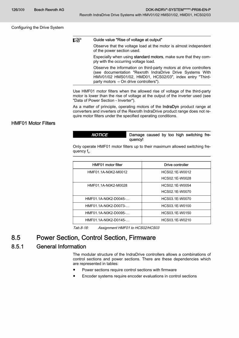
Guide value "Rise of voltage at output"Observe that the voltage load at the motor is almost independentof the power section used.Especially when using standard motors, make sure that they com‐ply with the occurring voltage load.Observe the information on third-party motors at drive controllers(see documentation "Rexroth IndraDrive Drive Systems WithHMV01/02 HMS01/02, HMD01, HCS02/03", index entry "Third-party motors → On drive controllers").
Use HMF01 motor filters when the allowed rise of voltage of the third-partymotor is lower than the rise of voltage at the output of the inverter used (see"Data of Power Section - Inverter").As a matter of principle, operating motors of the IndraDyn product range atconverters and inverters of the Rexroth IndraDrive product range does not re‐quire motor filters under the specified operating conditions.
HMF01 Motor Filters
Damage caused by too high switching fre‐quency!
NOTICE
Only operate HMF01 motor filters up to their maximum allowed switching fre‐quency fs.
HMF01 motor filter Drive controller
HMF01.1A-N0K2-M0012 HCS02.1E-W0012HCS02.1E-W0028
HMF01.1A-N0K2-M0028 HCS02.1E-W0054HCS02.1E-W0070
HMF01.1A-N0K2‑D0045-… HCS03.1E-W0070
HMF01.1A-N0K2‑D0073-… HCS03.1E-W0100
HMF01.1A-N0K2‑D0095-… HCS03.1E-W0150
HMF01.1A-N0K2‑D0145-… HCS03.1E-W0210
Tab.8-18: Assignment HMF01 to HCS02/HCS03
8.5 Power Section, Control Section, Firmware 8.5.1 General Information
The modular structure of the IndraDrive controllers allows a combinations ofcontrol sections and power sections. There are these dependencies whichare represented in tables:● Power sections require control sections with firmware● Encoder systems require encoder evaluations in control sections
Bosch Rexroth AG DOK-INDRV*-SYSTEM*****-PR06-EN-P Rexroth IndraDrive Drive Systems with HMV01/02 HMS01/02, HMD01, HCS02/03
126/309
Configuring the Drive System

8.5.2 Power Section - Control Section
Control sectionPower section
HMS01 HMS02 HMD01 HCS02 HCS03 HCS04.2
CSH01.1C 1) ■ ■ - ■ ■ -
CSH01.2C 1) ■ ■ - ■ ■ -
CSH01.3C 1) ■ ■ - ■ ■ ■
CSB01.1N 2) ■ ■ - ■ ■ ■
CSB01.1C 1) ■ ■ - ■ ■ ■
CDB01.1C 1) - - ■ - - -
CSH02.1B 4) ■ ■ - ■ ■ -
CSB02.1A 3) ■ ■ - ■ ■ ■
CSB02.1B 4) ■ ■ - ■ ■ ■
CSE02.1A 3) ■ ■ - ■ ■ ■
CDB02.1B 4) - - ■ - - -
■ Allowed- Not allowed1) Control section can be configured2) Control section cannot be configured3) Basic scope4) Extended scopeTab.8-19: Combination Control Section - Power Section
Do not exceed maximum number of plug-in actions!For a drive controller, the control section mustn't be mounted anddismounted more than a maximum of 20 times. If this number isexceeded, the electrical data of the internal connection can beabove the specified minimum requirements. This can cause mal‐function of the drive controllers.
8.5.3 Control Section - Firmware For scopes of functions and configurations of firmware versions, see Func‐tional Description of corresponding firmware version in chapter "ReferenceDocumentations".
Control section type1) Firmware version
CSB01 . 1 N -FC As of MPB-02VRS
CSB01 . 1 N -AN As of MPB-02VRS
CSB01 . 1 C As of MPB-02VRS
CDB01 . 1 C As of MPD-02VRS
CSH01 . 1 C As of MPH-02VRS
CSH01 . 2 C As of MPH-04VRS to MPH-05VRS
DOK-INDRV*-SYSTEM*****-PR06-EN-P Rexroth IndraDrive Drive Systems with HMV01/02 HMS01/02, HMD01, HCS02/03
Bosch Rexroth AG 127/309
Configuring the Drive System
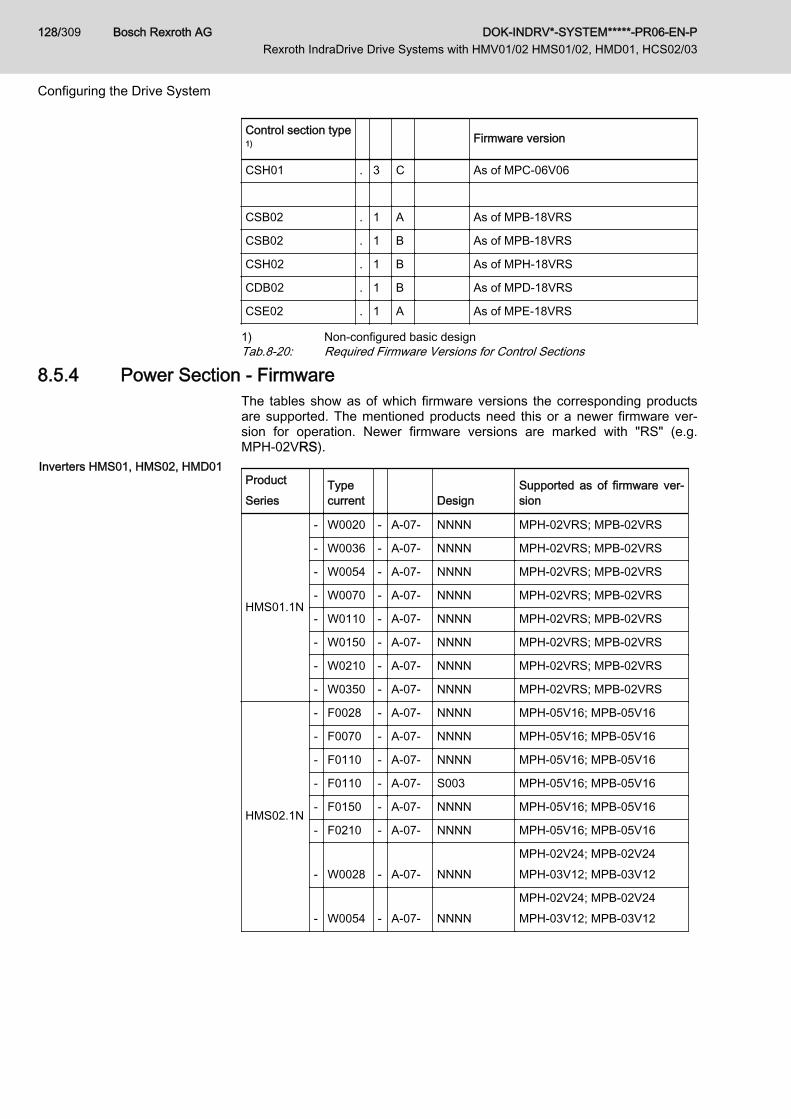
Control section type1) Firmware version
CSH01 . 3 C As of MPC-06V06
CSB02 . 1 A As of MPB-18VRS
CSB02 . 1 B As of MPB-18VRS
CSH02 . 1 B As of MPH-18VRS
CDB02 . 1 B As of MPD-18VRS
CSE02 . 1 A As of MPE-18VRS
1) Non-configured basic designTab.8-20: Required Firmware Versions for Control Sections
8.5.4 Power Section - FirmwareThe tables show as of which firmware versions the corresponding productsare supported. The mentioned products need this or a newer firmware ver‐sion for operation. Newer firmware versions are marked with "RS" (e.g.MPH‑02VRS).
Inverters HMS01, HMS02, HMD01ProductSeries
Typecurrent Design
Supported as of firmware ver‐sion
HMS01.1N
- W0020 - A-07- NNNN MPH-02VRS; MPB-02VRS
- W0036 - A-07- NNNN MPH-02VRS; MPB-02VRS
- W0054 - A-07- NNNN MPH-02VRS; MPB-02VRS
- W0070 - A-07- NNNN MPH-02VRS; MPB-02VRS
- W0110 - A-07- NNNN MPH-02VRS; MPB-02VRS
- W0150 - A-07- NNNN MPH-02VRS; MPB-02VRS
- W0210 - A-07- NNNN MPH-02VRS; MPB-02VRS
- W0350 - A-07- NNNN MPH-02VRS; MPB-02VRS
HMS02.1N
- F0028 - A-07- NNNN MPH-05V16; MPB-05V16
- F0070 - A-07- NNNN MPH-05V16; MPB-05V16
- F0110 - A-07- NNNN MPH-05V16; MPB-05V16
- F0110 - A-07- S003 MPH-05V16; MPB-05V16
- F0150 - A-07- NNNN MPH-05V16; MPB-05V16
- F0210 - A-07- NNNN MPH-05V16; MPB-05V16
- W0028 - A-07- NNNNMPH-02V24; MPB-02V24MPH-03V12; MPB-03V12
- W0054 - A-07- NNNNMPH-02V24; MPB-02V24MPH-03V12; MPB-03V12
Bosch Rexroth AG DOK-INDRV*-SYSTEM*****-PR06-EN-P Rexroth IndraDrive Drive Systems with HMV01/02 HMS01/02, HMD01, HCS02/03
128/309
Configuring the Drive System

ProductSeries
Typecurrent Design
Supported as of firmware ver‐sion
HMD01.1N
- W0012 - A-07- NNNN MPD-02VRS
- W0020 - A-07- NNNN MPD-02VRS
- W0036 - A-07- NNNN MPD-02VRS
Tab.8-21: Required Firmware Versions for Inverters
DOK-INDRV*-SYSTEM*****-PR06-EN-P Rexroth IndraDrive Drive Systems with HMV01/02 HMS01/02, HMD01, HCS02/03
Bosch Rexroth AG 129/309
Configuring the Drive System
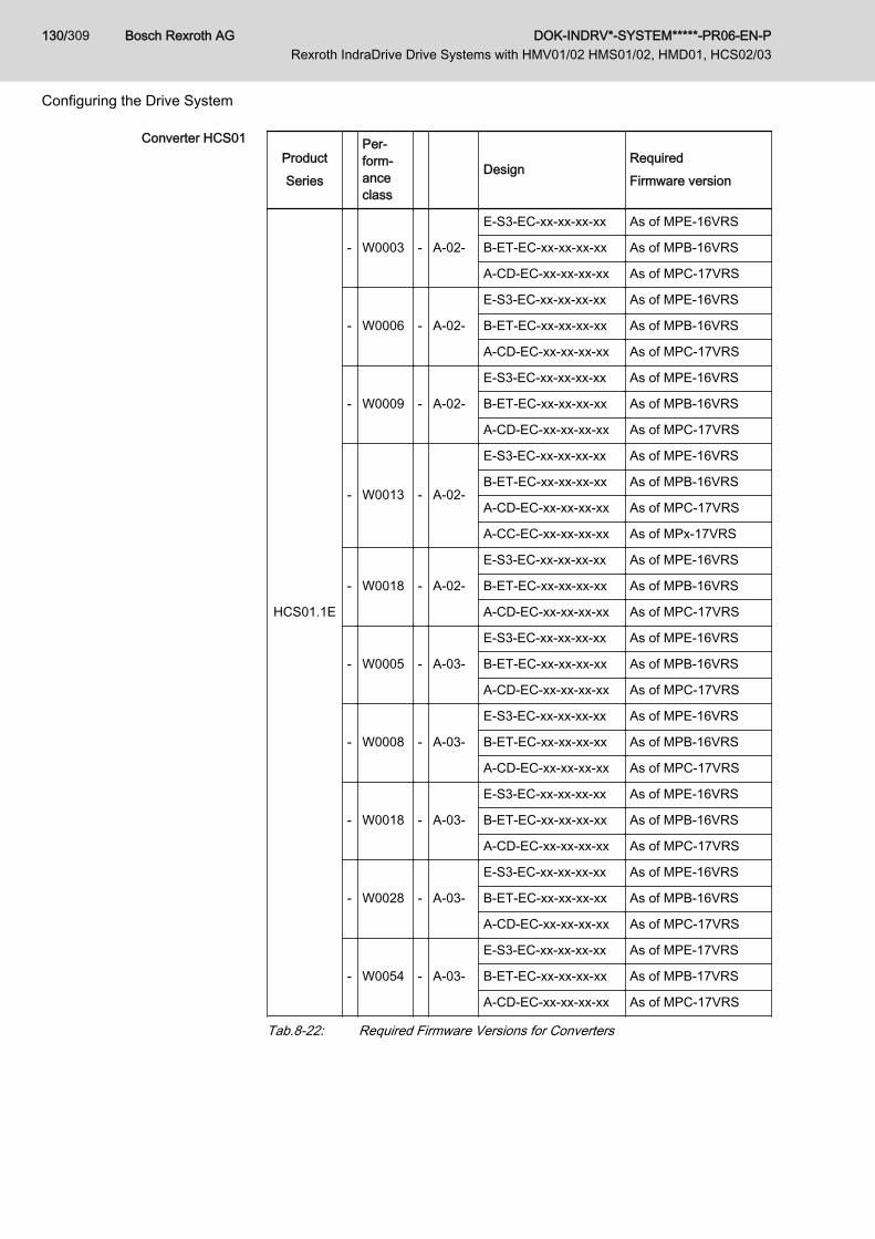
Converter HCS01ProductSeries
Per‐form‐anceclass
DesignRequiredFirmware version
HCS01.1E
- W0003 - A-02-
E-S3-EC-xx-xx-xx-xx As of MPE-16VRS
B-ET-EC-xx-xx-xx-xx As of MPB-16VRS
A-CD-EC-xx-xx-xx-xx As of MPC-17VRS
- W0006 - A-02-
E-S3-EC-xx-xx-xx-xx As of MPE-16VRS
B-ET-EC-xx-xx-xx-xx As of MPB-16VRS
A-CD-EC-xx-xx-xx-xx As of MPC-17VRS
- W0009 - A-02-
E-S3-EC-xx-xx-xx-xx As of MPE-16VRS
B-ET-EC-xx-xx-xx-xx As of MPB-16VRS
A-CD-EC-xx-xx-xx-xx As of MPC-17VRS
- W0013 - A-02-
E-S3-EC-xx-xx-xx-xx As of MPE-16VRS
B-ET-EC-xx-xx-xx-xx As of MPB-16VRS
A-CD-EC-xx-xx-xx-xx As of MPC-17VRS
A-CC-EC-xx-xx-xx-xx As of MPx-17VRS
- W0018 - A-02-
E-S3-EC-xx-xx-xx-xx As of MPE-16VRS
B-ET-EC-xx-xx-xx-xx As of MPB-16VRS
A-CD-EC-xx-xx-xx-xx As of MPC-17VRS
- W0005 - A-03-
E-S3-EC-xx-xx-xx-xx As of MPE-16VRS
B-ET-EC-xx-xx-xx-xx As of MPB-16VRS
A-CD-EC-xx-xx-xx-xx As of MPC-17VRS
- W0008 - A-03-
E-S3-EC-xx-xx-xx-xx As of MPE-16VRS
B-ET-EC-xx-xx-xx-xx As of MPB-16VRS
A-CD-EC-xx-xx-xx-xx As of MPC-17VRS
- W0018 - A-03-
E-S3-EC-xx-xx-xx-xx As of MPE-16VRS
B-ET-EC-xx-xx-xx-xx As of MPB-16VRS
A-CD-EC-xx-xx-xx-xx As of MPC-17VRS
- W0028 - A-03-
E-S3-EC-xx-xx-xx-xx As of MPE-16VRS
B-ET-EC-xx-xx-xx-xx As of MPB-16VRS
A-CD-EC-xx-xx-xx-xx As of MPC-17VRS
- W0054 - A-03-
E-S3-EC-xx-xx-xx-xx As of MPE-17VRS
B-ET-EC-xx-xx-xx-xx As of MPB-17VRS
A-CD-EC-xx-xx-xx-xx As of MPC-17VRS
Tab.8-22: Required Firmware Versions for Converters
Bosch Rexroth AG DOK-INDRV*-SYSTEM*****-PR06-EN-P Rexroth IndraDrive Drive Systems with HMV01/02 HMS01/02, HMD01, HCS02/03
130/309
Configuring the Drive System
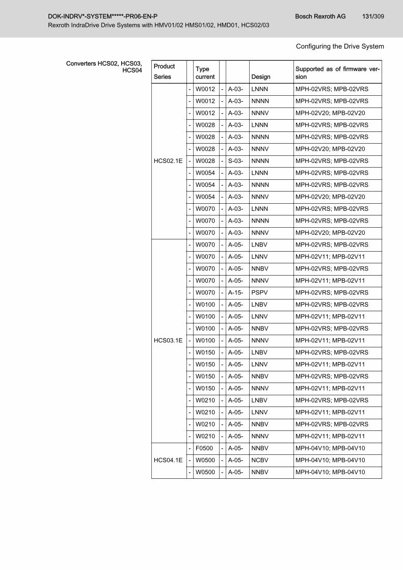
Converters HCS02, HCS03,HCS04 Product
Series Typecurrent Design
Supported as of firmware ver‐sion
HCS02.1E
- W0012 - A-03- LNNN MPH-02VRS; MPB-02VRS
- W0012 - A-03- NNNN MPH-02VRS; MPB-02VRS
- W0012 - A-03- NNNV MPH-02V20; MPB-02V20
- W0028 - A-03- LNNN MPH-02VRS; MPB-02VRS
- W0028 - A-03- NNNN MPH-02VRS; MPB-02VRS
- W0028 - A-03- NNNV MPH-02V20; MPB-02V20
- W0028 - S-03- NNNN MPH-02VRS; MPB-02VRS
- W0054 - A-03- LNNN MPH-02VRS; MPB-02VRS
- W0054 - A-03- NNNN MPH-02VRS; MPB-02VRS
- W0054 - A-03- NNNV MPH-02V20; MPB-02V20
- W0070 - A-03- LNNN MPH-02VRS; MPB-02VRS
- W0070 - A-03- NNNN MPH-02VRS; MPB-02VRS
- W0070 - A-03- NNNV MPH-02V20; MPB-02V20
HCS03.1E
- W0070 - A-05- LNBV MPH-02VRS; MPB-02VRS
- W0070 - A-05- LNNV MPH-02V11; MPB-02V11
- W0070 - A-05- NNBV MPH-02VRS; MPB-02VRS
- W0070 - A-05- NNNV MPH-02V11; MPB-02V11
- W0070 - A-15- PSPV MPH-02VRS; MPB-02VRS
- W0100 - A-05- LNBV MPH-02VRS; MPB-02VRS
- W0100 - A-05- LNNV MPH-02V11; MPB-02V11
- W0100 - A-05- NNBV MPH-02VRS; MPB-02VRS
- W0100 - A-05- NNNV MPH-02V11; MPB-02V11
- W0150 - A-05- LNBV MPH-02VRS; MPB-02VRS
- W0150 - A-05- LNNV MPH-02V11; MPB-02V11
- W0150 - A-05- NNBV MPH-02VRS; MPB-02VRS
- W0150 - A-05- NNNV MPH-02V11; MPB-02V11
- W0210 - A-05- LNBV MPH-02VRS; MPB-02VRS
- W0210 - A-05- LNNV MPH-02V11; MPB-02V11
- W0210 - A-05- NNBV MPH-02VRS; MPB-02VRS
- W0210 - A-05- NNNV MPH-02V11; MPB-02V11
HCS04.1E
- F0500 - A-05- NNBV MPH-04V10; MPB-04V10
- W0500 - A-05- NCBV MPH-04V10; MPB-04V10
- W0500 - A-05- NNBV MPH-04V10; MPB-04V10
DOK-INDRV*-SYSTEM*****-PR06-EN-P Rexroth IndraDrive Drive Systems with HMV01/02 HMS01/02, HMD01, HCS02/03
Bosch Rexroth AG 131/309
Configuring the Drive System
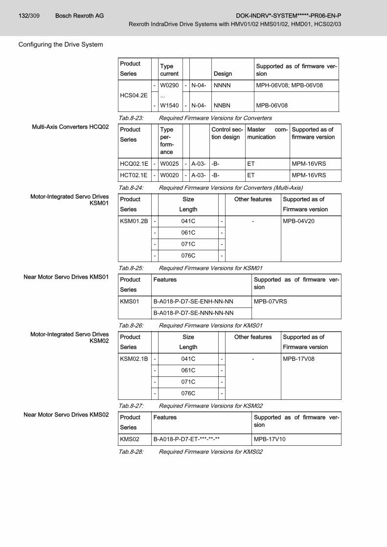
ProductSeries
Typecurrent Design
Supported as of firmware ver‐sion
HCS04.2E- W0290
...W1540
- N-04- NNNN MPH-06V08; MPB-06V08
- - N-04- NNBN MPB-06V08
Tab.8-23: Required Firmware Versions for ConvertersMulti-Axis Converters HCQ02 Product
Series Type
per‐form‐ance
Control sec‐tion design
Master com‐munication
Supported as offirmware version
HCQ02.1E - W0025 - A-03- -B- ET MPM-16VRS
HCT02.1E - W0020 - A-03- -B- ET MPM-16VRS
Tab.8-24: Required Firmware Versions for Converters (Multi-Axis)Motor-Integrated Servo Drives
KSM01 ProductSeries
SizeLength
Other features Supported as ofFirmware version
KSM01.2B - 041C - - MPB-04V20
- 061C -
- 071C -
- 076C -
Tab.8-25: Required Firmware Versions for KSM01Near Motor Servo Drives KMS01 Product
SeriesFeatures Supported as of firmware ver‐
sion
KMS01 B-A018-P-D7-SE-ENH-NN-NN MPB-07VRS
B-A018-P-D7-SE-NNN-NN-NN
Tab.8-26: Required Firmware Versions for KMS01Motor-Integrated Servo Drives
KSM02 ProductSeries
SizeLength
Other features Supported as ofFirmware version
KSM02.1B - 041C - - MPB-17V08
- 061C -
- 071C -
- 076C -
Tab.8-27: Required Firmware Versions for KSM02Near Motor Servo Drives KMS02 Product
SeriesFeatures Supported as of firmware ver‐
sion
KMS02 B-A018-P-D7-ET-***-**-** MPB-17V10
Tab.8-28: Required Firmware Versions for KMS02
Bosch Rexroth AG DOK-INDRV*-SYSTEM*****-PR06-EN-P Rexroth IndraDrive Drive Systems with HMV01/02 HMS01/02, HMD01, HCS02/03
132/309
Configuring the Drive System

8.5.5 Motor - Firmware
Motor typeWith encoder system
Firmware version
NotesFrom
MHD MPx-02VRS
MKD MPx-02VRS
MKE MPx-02VRS
A, C MPx-16VRS
MSK MPx-02VRS
MSM M0 MPx-16VRS
MAF MPx-02VRS
M1, M2, M6, S1, S2, S6, N0 MPx-16VRS
MAD MPx-02VRS
M1, M2, M6, S1, S2, S6, N0 MPx-16VRS
MSP MPx-05VRS
MSD MPx-02VRS
M1, M2, S1, S2 MPx-16VRS
IndraDyn LMLF MPx-02VRS
MBS
IndraDyn HMBSxx2 MPx-02VRS
IndraDyn TMBT MPx-02VRS
Tab.8-29: Firmware Versions vs. Motors
8.5.6 Encoder System - Encoder EvaluationThe control sections of the Rexroth IndraDrive product range support differ‐ent encoder systems. Evaluation of these encoder systems requires the men‐tioned encoder evaluations as optional modules or optional equipment.
Operating other encoder systems than the mentioned ones re‐quires detailed control of the technical data of the encoder systemused and the interface specification of the control section.When using third-party encoders, observe that the optional mod‐ules provide different supply voltages.
DOK-INDRV*-SYSTEM*****-PR06-EN-P Rexroth IndraDrive Drive Systems with HMV01/02 HMS01/02, HMD01, HCS02/03
Bosch Rexroth AG 133/309
Configuring the Drive System

Supported by Firmware Versions up to MPx-08
Encoder sys‐tem 1)
Notes Optionalmodule en‐coder evalu‐
ation
Cable for direct con‐nection 2)
Rexroth IndraDyn S, A, T, H, L
R0 Resolver EN1 IKS4043
R1 Resolver with integrated absolute multi-turn encoder EN1 IKS4043
S0 Optical encoder single-turn IIC, 512 increments, supply voltage 8 V EN1 IKS4042
S1 Optical encoder single-turn HIPERFACE, 128 increments, supplyvoltage 7 … 12 V
ENS RKG4200
S2 Optical encoder single-turn EnDat2.1, 2048 increments, supply volt‐age 12 V
ENS RKG4200
S3 Capacitive encoder single-turn HIPERFACE, 16 increments, supplyvoltage 7 … 12 V
ENS RKG4200
S5 Optical encoder, single-turn with 128 increments (at QSK motors)At HCQ02 requires interface code "1S" or "1N"(e.g. HCQ02.1E-W025- A-03-B-L4-1S)
ES RKG4200
S6(preliminary)
Optical encoder single-turn EnDat2.1, 2048 increments, supply volt‐age 12 V
ENS tbd
EC
M0 Optical encoder multi-turn absolute IIC, 512 increments, supply volt‐age 8 V
EN1 IKS4042
M1 Optical encoder multi-turn absolute HIPERFACE, 128 increments,supply voltage 7 … 12 V
ENS RKG4200
M2 Optical encoder multi-turn absolute EnDat2.1, 2048 increments,supply voltage 12 V
ENS RKG4200
M3 Capacitive encoder multi-turn absolute HIPERFACE, 16 increments,supply voltage 7 … 12 V
ENS RKG4200
M5 Optical encoder, multi-turn absolute with 128 increments (at QSKmotors)At HCQ02 requires interface code "1S" or "1N"(e.g. HCQ02.1E-W025- A-03-B-L4-1S)
ES RKG4200
M6(preliminary)
Optical encoder multi-turn absolute EnDat2.1, 2048 increments,supply voltage 12 V
ENS tbd
C0 Optical encoder incremental 1 Vpp, 2048 increments (sin/cos) EN2 RKG0014
SHL01.1 Hall sensor box for position detection of primary part of, for exam‐ple, IndraDyn L and LSF motors
EN13) IKS4042
SHL02.1 Hall sensor box for position detection of primary part of, for exam‐ple, IndraDyn L and LSF motors
EN14) IKS4042
ENS RKG0027
SHL03.1 Hall sensor adapter box for position detection of the primary part ofIndraDyn L MCL motors
EC RKG0049
Bosch Rexroth AG DOK-INDRV*-SYSTEM*****-PR06-EN-P Rexroth IndraDrive Drive Systems with HMV01/02 HMS01/02, HMD01, HCS02/03
134/309
Configuring the Drive System

Encoder sys‐tem 1)
Notes Optionalmodule en‐coder evalu‐
ation
Cable for direct con‐nection 2)
Rexroth ServoDyn D servo motors SF
STG Single-turn encoder, absolute EN2 RKG0015
MTG Multi-turn encoder, 4096 revs. absolute EN2 RKG0015
Rexroth ServoDyn D servo motors SR
Resolver Not supported
Rexroth motors MKE, MKD, MHD
A See encoder system S1 ENS Depending on motortype: RKG0020 or
RKG0022C See encoder system M1 ENS
B See encoder system S2 ENS
D See encoder system M2 ENS
K See encoder system R1 EN1 Depending on motortype: IKS0223 or
IKS0226V See encoder system R0 EN1
N See encoder system S0 EN1
P See encoder system M0 EN1
1) See following note2) Without extension and control cabinet duct3) Up to MPx04VRS, only allowed on option 2 (X8)4) Up to MPx04VRS, only allowed on option 2 (X8); as of MPx05VRS
configurableTab.8-30: Combination Control Section Equipment - Motor Encoder
For the encoder system, see the type code of the selected motor.
Fig.8-8: Type Code Section of Motor
DOK-INDRV*-SYSTEM*****-PR06-EN-P Rexroth IndraDrive Drive Systems with HMV01/02 HMS01/02, HMD01, HCS02/03
Bosch Rexroth AG 135/309
Configuring the Drive System
8.6 Combination With Other Rexroth Components8.6.1 Combination With Components of the Control Range
Rexroth IndraControl VOperator Terminals VCP
The VCP operator terminals allow comfortable operation of the RexrothIndraDrive drive system with the IndraControl V control range.The operator terminals VCP02, VCP05, VCP08, VCP20 and VCP25 are suit‐ed for control cabinet mounting and operated via the serial interface RS232(X2) of the control sections.The comfort control panel VCP01 is operated directly at the drive controller atthe connection "H1". It then replaces the supplied standard control panel. Thescope of functions is described in the Operating Instructions "RexrothIndraDrive C Drive Controllers HCS02.1, HCS03.1".
Simultaneous operation of VCP operator terminals and standardcontrol panels or comfort control panels is allowed.
8.6.2 sercos Analog ConverterGeneral Information
To modernize machines, the Rexroth IndraDrive range provides the possibili‐ty of operating drive controllers of the "ANAX" and "Diax 02" ranges with ana‐log command value input.
sercos Analog ConverterThe sercos analog converter is used to● connect control units with sercos interface to components with analog
interface● convert sercos position command values to analog speed command val‐
uesThe sercos analog converter consists of:● Housing for HAC01.1-002 control sections● Configurable control section with sercos master communication
– For MAC motors at TDM drive controllers:BASIC CDB01.1C-SE-EN1-EN1-MA1-MA1--NN-S-NN-FW
– For MDD motors at DDS drive controllers:BASIC CDB01.1C-SE-EN2-EN2-MA1-MA1--NN-S-NN-FW
– BASIC CDB01.1C-SE-ENS-ENS-MA1-MA1-NN-S-NN-FW (prelimi‐nary)
● Firmware e.g. FWA-INDRV*-MPD-04VRS-**-*-***-**● Optional accessory HAS01.1-065-NNN-CN
Make sure that the parameter "P‑0‑0860, Converter configuration"has been set to operation as "sercos analog converter"(bit 15 = 1). Wrong setting will generate the error message"F8091 Power section defective".
Bosch Rexroth AG DOK-INDRV*-SYSTEM*****-PR06-EN-P Rexroth IndraDrive Drive Systems with HMV01/02 HMS01/02, HMD01, HCS02/03
136/309
Configuring the Drive System
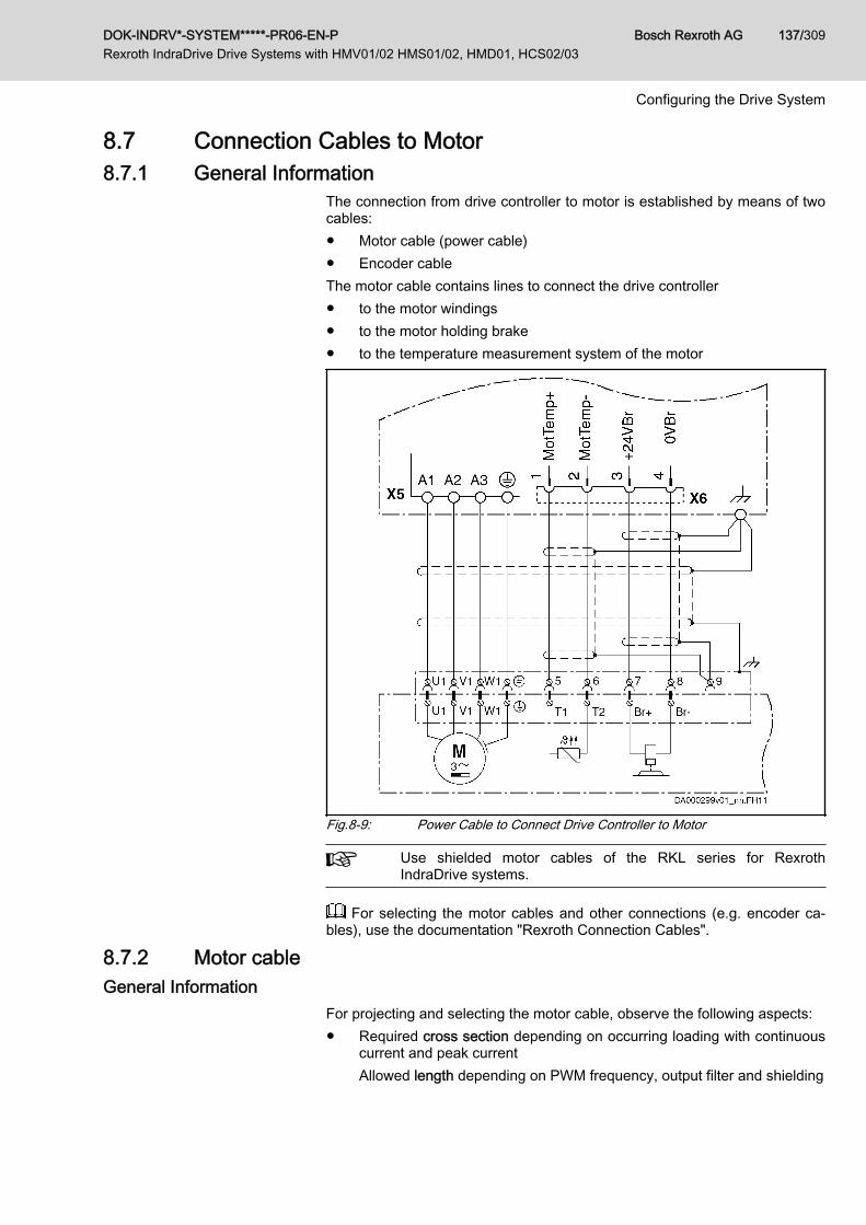
8.7 Connection Cables to Motor8.7.1 General Information
The connection from drive controller to motor is established by means of twocables:● Motor cable (power cable)● Encoder cableThe motor cable contains lines to connect the drive controller● to the motor windings● to the motor holding brake● to the temperature measurement system of the motor
Fig.8-9: Power Cable to Connect Drive Controller to Motor
Use shielded motor cables of the RKL series for RexrothIndraDrive systems.
For selecting the motor cables and other connections (e.g. encoder ca‐bles), use the documentation "Rexroth Connection Cables".
8.7.2 Motor cableGeneral Information
For projecting and selecting the motor cable, observe the following aspects:● Required cross section depending on occurring loading with continuous
current and peak currentAllowed length depending on PWM frequency, output filter and shielding
DOK-INDRV*-SYSTEM*****-PR06-EN-P Rexroth IndraDrive Drive Systems with HMV01/02 HMS01/02, HMD01, HCS02/03
Bosch Rexroth AG 137/309
Configuring the Drive System

● Length due to voltage drop on connection line to motor brake● Other mechanical requirements resulting from use of motor cable, such
as bending radiuses, material compatibility; see documentation "RexrothConnection Cables".
Motor Cable Selection To find the appropriate cable for the selected combination of motor and
drive controller, see documentation "Rexroth Connection Cables".
Allowed Length of Motor CableThe length of the motor power cable is limited to protect the drive controllers.The longer the motor cable and the higher the switching frequency fs of thedrive controller which has been set, the higher the occurring losses.
Observe that the allowed motor cable length depends on theswitching frequency fs of the power output stage which has beenset. As a matter of principle, the higher the switching frequency,the shorter the allowed cable length to protect the drive control‐lers against overload.Only set such switching frequencies which are supported by theinvolved components! Observe the technical data for drive con‐trollers and motors.See also Parameter Description "P‑0‑0001, Switching frequencyof the power output stage".
Allowed Cable Lengths at Ambient Temperature Ta_work ≤ 40 °C according toEN 60 204:
PWM frequency /kHz
Allowed cable length / m
Without motor filter With motor filter3)
Shielded Unshielded1)
2 2) 100 175 200
4 75 150 200
8 38 150 Not allowed
12 25 Not allowed Not allowed
16 18 Not allowed Not allowed
1) Only allowed for HCS02/HCS03 drive controllers, observe note "Un‐shielded motor cables" below
2) Depending on the drive controller which is used3) Additional components HMFTab.8-31: Line Lengths
Bosch Rexroth AG DOK-INDRV*-SYSTEM*****-PR06-EN-P Rexroth IndraDrive Drive Systems with HMV01/02 HMS01/02, HMD01, HCS02/03
138/309
Configuring the Drive System
Unshielded motor cablesOperation with unshielded motor cable● aims at applications with "sensorless operation" (open-loop
operation)● does not include the control voltage lines to the motor; brake
supply and evaluation of the temperature sensors in the mo‐tor might possibly require further measures
● requires additional measures with regard to EMC on the partof the operating company
For lines connected in parallel, half the indicated lengths apply.
Voltage Drop on Connection to Motor Holding BrakeThe motor holding brake is controlled via the drive controller. For this pur‐pose, the 24V supply is connected to the output at the connection point X6.To operate the motor holding brake reliably, observe its requirements onpower supply.For operating the integrated motor holding brakes of the Rexroth IndraDynmotor line at Rexroth IndraDrive controllers with Rexroth connection cables,the data of 24V supply are considered as guide values.
For the data of 24V supply, see Project Planning Manual "RexrothIndraDrive Supply Units and Power Sections" → Chapter of the respective de‐vice → "Technical Data" → "Basic Data" → "Data for Control Voltage Supply".
Mechanical RequirementsDepending on the application, there are different requirements.
See the technical data of the cables in the documentation "Rexroth Con‐nection Cables" for whether the properties comply with the requirements.
Third-Party Power CablesRequirements on third-party motor power cables:Maximum allowed cable length at A1, A2, A3:● See chapter 8.7 Connection Cables to Motor, page 137Maximum allowed capacitance per unit length at A1, A2, A3:● Against ground, each: 0.5 nF/m● Against each other: 0.5 nF/mMaximum allowed inductance per unit length at A1, A2, A3:● 100 nH/m each
If you use third-party motor cables not corresponding to the re‐quirements, Rexroth's guarantee for the drive system will expire.Use ready-made cables by Rexroth.
To select the cables, use the documentation "Rexroth Connection Ca‐bles".
DOK-INDRV*-SYSTEM*****-PR06-EN-P Rexroth IndraDrive Drive Systems with HMV01/02 HMS01/02, HMD01, HCS02/03
Bosch Rexroth AG 139/309
Configuring the Drive System

8.7.3 Encoder Cables To find the appropriate cable for the selected combination of motor with
encoder and the respective encoder evaluation, see documentation "RexrothConnection Cables" in chapter "Select Encoder Cables"
8.8 Using Rexroth IndraDyn Motors8.8.1 Rexroth IndraDyn H – Synchronous Kit Spindle Motors
When selecting the drive controllers and supply units, make sure that, whenusing MBS motors, the occurring peak power does not cause overvoltage inthe DC bus.Therefore, make sure for your selection that the developed peak power of themotor is smaller than the peak power (or sum of peak powers) of the brakingresistors at the DC bus. Take into account that, in particular during operationin the field weakening range, high peak powers occur when control voltagefails.The assignment table below shows the supply units or drive controllers basi‐cally suited for operating MBS motors.
Drive controller or supplyunit
IndraDyn H Notes
MBS
HMV01 ■
HMV02 ■
HCS02 -Capacity PBS of braking re‐sistor is too low for occur‐
ring peak power.
HCS03 ■
■ Allowed- Not allowedTab.8-32: Combinations
Bosch Rexroth AG DOK-INDRV*-SYSTEM*****-PR06-EN-P Rexroth IndraDrive Drive Systems with HMV01/02 HMS01/02, HMD01, HCS02/03
140/309
Configuring the Drive System

9 Circuits for the Mains Connection9.1 General Information
The controls of mains contactor and DC bus short circuit for supply units anddrive controllers suggested in this documentation describe the functional prin‐ciples.
The selection of the control and its effects depend on the extentof the functions and the operating sequence of the installation ormachine. The selection of the control falls to the installation ormachine manufacturer’s responsibility.
9.2 Mains Contactor, Bb ContactThe central components in the circuit for the mains connection are:● Mains contactor● Bb contact
Mains Contactor Mains contactors in the power circuit of the mains connection switch the pow‐er supply. In the case of error, mains contactors interrupt the energy flowfrom the supply mains and therewith the power supply of the drive controllers.When the drive system is supplied via another circuit, e.g. in regenerativeform via permanently driven motor:● Integrate this supply in the circuit for the mains connection.● Take this into account when selecting the drive controllers and addition‐
al components.
Risk of fire caused by the "sacrificing behav‐ior" of the ZKS stage!
NOTICE
The "ZKS" input activates the "DC bus short circuit" function, when the 24Vcontrol voltage has not been applied and when there isn't any current flowingto the input. This condition can occur in the following situations:● Failure of 24V control voltage● Wire break● Activation of serially connected contacts (e.g. axis limit switches)If the kinetic energy of the mechanical axis system regenerated when brakingis greater than the energy absorption capacity of HLB, the HLB device re‐mains active when braking via ZKS takes place, until it is thermally destroyed(sacrificing behavior). Risk of fire! In this case, braking via ZKS may onlycome into effect in the case of an emergency (e.g. activation of an axis limitswitch causes the mains supply to be cut off and simultaneously causes the24V supply of the ZKS input to be interrupted).Install a 24V UPS, if the "sacrificing behavior" of HLB is relevant to your drivesystem in the case of an emergency. This prevents the braking via ZKSwhich causes HLB to be destroyed due to the failure of the 24V control volt‐age. Braking via ZKS then will only take place in cases of emergency.
Switching off the power supply protects the supply units and drive controllersagainst permanently present error states and damage being caused by thepersistent effect of these error states.
DOK-INDRV*-SYSTEM*****-PR06-EN-P Rexroth IndraDrive Drive Systems with HMV01/02 HMS01/02, HMD01, HCS02/03
Bosch Rexroth AG 141/309
Circuits for the Mains Connection

The mains contactor does not replace overcurrent protection devices connec‐ted in the incoming circuit, but is a functional complement. The mains contac‐tor itself needs overcurrent protection to allow reliably operating it afterswitch-off processes.In conjunction with the corresponding "circuit for the mains connection", themains contactor only switches the DC bus voltage to the drive controllerswhen they are ready to consume power voltage and when there isn't anyerror present.In order that the drive controllers can signal their status, they must be sup‐plied with the 24V control voltage.The following scenarios are typical cases in which the circuit for the mainsconnection is to switch off the mains contactor and lead to the power supplybeing switched off:● Short circuit at the output of the inverters with error "F8060 Overcurrent
in power section"● Switch-on upon activated DC bus short circuit (ZKS) with error message
"F2820 Braking resistor overload"● Operation at mains voltages outside of the allowed range with error
message "F2815 Overvoltage in mains"
See also firmware documentation "Troubleshooting Guide" which con‐tains the descriptions of the error messages (diagnostic messages).
Bb Contact The mains contactor has to be controlled depending on the error status of thesupply unit or drive controller.At the control section of the HCS drive controllers and at the supply units,there is an isolated contact available for this purpose (relay contact Rel1) thathas been configured as Bb contact in the condition as supplied. When the Bbcontact closes, the drive or drive system is ready for power on.
Danger of consequential damage!Make sure that the mains contactor interrupts power supply fromthe mains when the Bb contact opens.
Load of Bb contactObserve the load capability limits of the Bb contact (see ProjectPlanning Manual "Rexroth IndraDrive, Drive Controllers, ControlSections" for the control section used [connection point X31.1,X31.2]).Control contactors with AC excitation and contactors exceedingthe load capability limits of the involved contact elements (Bb con‐tacts etc.) via contactor relays.
See also Functional Description of firmware → Power Supply
Bosch Rexroth AG DOK-INDRV*-SYSTEM*****-PR06-EN-P Rexroth IndraDrive Drive Systems with HMV01/02 HMS01/02, HMD01, HCS02/03
142/309
Circuits for the Mains Connection

Suppressor circuit for contactor coilWhen the mains contactor is switched off, the contactor coil cau‐ses overvoltages. These overvoltages may result in prematurefailure of the Bb contact.To attenuate overvoltages, use:● For contactor coils with DC voltage: Overvoltage limiters with
diode combination● For contactor coils with AC voltage: VaristorsAvoid varistors and RC elements at contactor coils for DC volt‐age, because varistors are subject to aging and increase their re‐verse currents, and RC elements can overload the switching ca‐pacity of the Bb contact.
Fig.9-1: Recommended Suppressor CircuitSwitching on the Power Supply Switch-on sequence
1. Apply 24V control voltage2. Wait for readiness for operation of the connected components3. Switch on power supply (e.g. close mains contactor)
Switching off the Power Supply When mains contactor is switched off frequentlyIn order to prevent the external mains contactor from being over‐loaded by the load current in the case of frequent switch-off:● First switch off the drive, e.g. via drive enable in the master
communication● Then switch off the mains contactor
Switch-off sequence1. Switch drive off2. Switch power supply off3. Switch 24V control voltage off, if required
Using and Arranging the MainsContactor
For HCS drive controllers of the Rexroth IndraDrive C product range, use anexternal mains contactor in the main connection for the circuit. Connect themains contactor electrically between mains filter and mains input (withHCS03 devices and HNK01 mains filters, the mains contactor may be con‐nected electrically before the HNK01 mains filter).The HMV01.1 supply units of the Rexroth IndraDrive M range have an inte‐grated mains contactor (exception: HMV01.1R-W0120 have no integratedmains contactor and require an external mains contactor).
DOK-INDRV*-SYSTEM*****-PR06-EN-P Rexroth IndraDrive Drive Systems with HMV01/02 HMS01/02, HMD01, HCS02/03
Bosch Rexroth AG 143/309
Circuits for the Mains Connection

Lethal injuries caused by live parts with morethan 50 V!
WARNING
Design and install the mains connection according to the valid standards.Observe the protection goals● Electrical safety● Mechanical safety in the case of incorrect movements● Protection against fireMake sure you can provide evidence of the mechanisms of protection bymeans of FMEA and hazard analysis.
Make use of the protection by mains contactors in the mains connection.
For the data for the rating of appropriate mains contactors incl. fuses andcable cross section, see Project Planning Manual "Rexroth IndraDrive SupplyUnits and Power Sections" → Chapter of the respective device → "TechnicalData" → "Basic Data" → table "Data for Mains Voltage Supply".
Using and Arranging an AdditionalMains Contactor
When the safety regulations require the circuit interruption in the mains con‐nection to be carried out in redundant form, it is necessary to have additionalmains contactors in the mains connection.Additional mains contactors are allowed at● HMV supply units● HCS drive controllers
Place the additional mains contactor electrically before:● Mains filter● Mains choke● Mains contactor (integrated or externally installed)● Mains input of supply unit or drive controllerObserve the following aspect for PLC programming:The additional mains contactor must already have been connec‐ted, before the request "power ON" is applied to the supply unit ordrive controller.
Input EIN2If the supply unit is operated with an additional mains contactor,the signal at the input EIN2 (X32.4) must be switched to level "L"within the tolerated mains failure time, when this additional mainscontactor is switched off.See also "F2819 Mains failure" in the firmware documentation"Troubleshooting Guide"
At installations with additional mains contactor, there are 2 mains contactorseffective:1. Integrated or external mains contactor of the supply unit or drive control‐
ler which is controlled by the circuit for mains connection2. Additional mains contactor which is controlled by an independent circuit
(e.g., from a PLC)
Bosch Rexroth AG DOK-INDRV*-SYSTEM*****-PR06-EN-P Rexroth IndraDrive Drive Systems with HMV01/02 HMS01/02, HMD01, HCS02/03
144/309
Circuits for the Mains Connection
9.3 Circuits for Mains Connection of Rexroth IndraDrive C DriveControllers
9.3.1 General InformationThe mains contactor connected in the incoming circuit controls the energyflow to the drive controller. This allows separation from the mains in the caseof error. The Bb contact at the control section of the drive controller or the Bbcontact of the mains supply decisively influences the circuit.
Circuits HCS02 For HCS02 drive controllers, the following circuits for the mains connectionare described:● Control of external mains contactor● Control of external mains contactor for devices with integrated control
voltage supply● Control of external mains contactor with DC bus resistor unit HLB01.1C
Circuits HCS03 For HCS03 drive controllers, the following circuits for the mains connectionare described:Control of external mains contactor
Configuration "Rel 1" as Bb Con‐tact
Power voltage is only switched to drive system, when the closing of the Bbcontact signals readiness for power voltage on.For this purpose, there is the isolated contact "Rel 1" at the control sections.The behavior of this contact can be configured via the parameter "P-0-0860,Converter configuration":● Behaves as converter, if drive controller is to get supply voltage via
mains connection (e.g., for type of mains connection "individual supply"or "central supply")
● Behaves as inverter, if drive controller is to get supply voltage via con‐nection DC bus (L+, L-) (e.g., for type of mains connection "central sup‐ply" as supplied device)
Include the converter contacts in the circuit in such a way that they make themains contactor drop out in the case of error (when the contact opens).You can assign other information to the "Rel 1" contacts of the drive control‐lers configured as inverters. Via this contact you can, for example, control asecond holding brake by entering a signal from "S-0-0398, IDN list of configu‐rable data in signal status word" in parameter "P-0-0300, Digital I/Os, assign‐ment list".(See also Functional Description of firmware: "Power Supply" and ParameterDescription of firmware for P-0-0300 and P-0-0861)
9.3.2 Control of External Mains Contactor for HCS02 and HCS03General Information
Risk of damage!NOTICEBefore switching the drive controller on again, wait at least for 300 ms plusthe switch-off delay of the mains contactor.
DOK-INDRV*-SYSTEM*****-PR06-EN-P Rexroth IndraDrive Drive Systems with HMV01/02 HMS01/02, HMD01, HCS02/03
Bosch Rexroth AG 145/309
Circuits for the Mains Connection
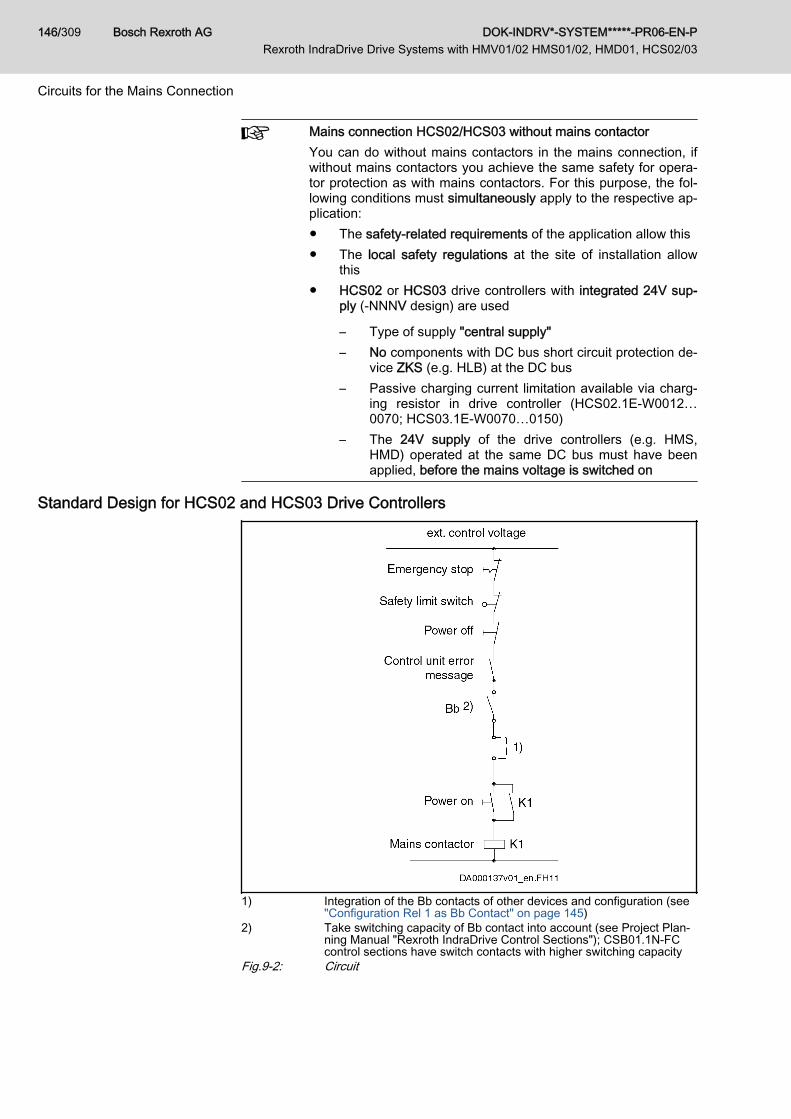
Mains connection HCS02/HCS03 without mains contactorYou can do without mains contactors in the mains connection, ifwithout mains contactors you achieve the same safety for opera‐tor protection as with mains contactors. For this purpose, the fol‐lowing conditions must simultaneously apply to the respective ap‐plication:● The safety-related requirements of the application allow this● The local safety regulations at the site of installation allow
this● HCS02 or HCS03 drive controllers with integrated 24V sup‐
ply (‑NNNV design) are used
– Type of supply "central supply"– No components with DC bus short circuit protection de‐
vice ZKS (e.g. HLB) at the DC bus– Passive charging current limitation available via charg‐
ing resistor in drive controller (HCS02.1E-W0012…0070; HCS03.1E-W0070…0150)
– The 24V supply of the drive controllers (e.g. HMS,HMD) operated at the same DC bus must have beenapplied, before the mains voltage is switched on
Standard Design for HCS02 and HCS03 Drive Controllers
1) Integration of the Bb contacts of other devices and configuration (see"Configuration Rel 1 as Bb Contact" on page 145)
2) Take switching capacity of Bb contact into account (see Project Plan‐ning Manual "Rexroth IndraDrive Control Sections"); CSB01.1N-FCcontrol sections have switch contacts with higher switching capacity
Fig.9-2: Circuit
Bosch Rexroth AG DOK-INDRV*-SYSTEM*****-PR06-EN-P Rexroth IndraDrive Drive Systems with HMV01/02 HMS01/02, HMD01, HCS02/03
146/309
Circuits for the Mains Connection
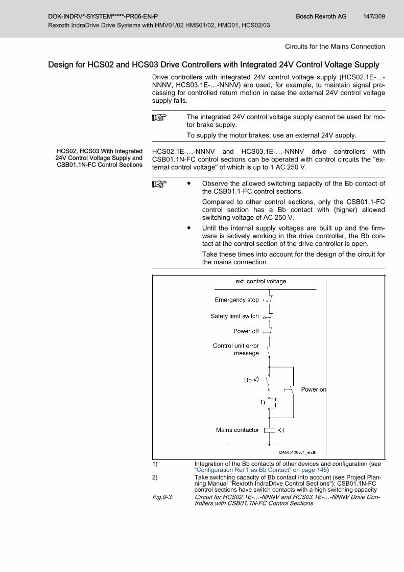
Design for HCS02 and HCS03 Drive Controllers with Integrated 24V Control Voltage SupplyDrive controllers with integrated 24V control voltage supply (HCS02.1E-…-NNNV, HCS03.1E-…-NNNV) are used, for example, to maintain signal pro‐cessing for controlled return motion in case the external 24V control voltagesupply fails.
The integrated 24V control voltage supply cannot be used for mo‐tor brake supply.To supply the motor brakes, use an external 24V supply.
HCS02, HCS03 With Integrated24V Control Voltage Supply andCSB01.1N-FC Control Sections
HCS02.1E-…-NNNV and HCS03.1E-…-NNNV drive controllers withCSB01.1N-FC control sections can be operated with control circuits the "ex‐ternal control voltage" of which is up to 1 AC 250 V.
● Observe the allowed switching capacity of the Bb contact ofthe CSB01.1‑FC control sections.Compared to other control sections, only the CSB01.1‑FCcontrol section has a Bb contact with (higher) allowedswitching voltage of AC 250 V.
● Until the internal supply voltages are built up and the firm‐ware is actively working in the drive controller, the Bb con‐tact at the control section of the drive controller is open.Take these times into account for the design of the circuit forthe mains connection.
1) Integration of the Bb contacts of other devices and configuration (see"Configuration Rel 1 as Bb Contact" on page 145)
2) Take switching capacity of Bb contact into account (see Project Plan‐ning Manual "Rexroth IndraDrive Control Sections"); CSB01.1N-FCcontrol sections have switch contacts with a high switching capacity
Fig.9-3: Circuit for HCS02.1E-…-NNNV and HCS03.1E-…-NNNV Drive Con‐trollers with CSB01.1N-FC Control Sections
DOK-INDRV*-SYSTEM*****-PR06-EN-P Rexroth IndraDrive Drive Systems with HMV01/02 HMS01/02, HMD01, HCS02/03
Bosch Rexroth AG 147/309
Circuits for the Mains Connection
9.3.3 Circuits HCS02 and HCS03 with DC Bus Resistor Unit HLB01.1C orHLB01.1D
Application Use this variant, when● only motors with permanent magnet excitation are connected● motors with permanent magnet excitation and asynchronous motors (in‐
duction machines) are connectedFeatures Due to the DC bus short circuit (ZKS), motors with permanent magnet excita‐
tion can be decelerated even if the electronic system of the drive is disturbed.
Personal injury caused by uncontrolled axismotion!
WARNING
The DC bus short circuit protects machines in the case of drive errors. By it‐self it cannot assume the function of personal protection. In the case of errorsin the drive or supply unit, uncontrolled drive motion can occur even when theDC bus short circuit has been activated.Asynchronous machines do not brake when the DC bus has been short-circuited. Personal injury can occur according to the machine design.Install additional monitors and protective devices on the installation side.
Suggested Circuit Connect the Bb contact of HLB in series with the Bb contacts of
the involved IndraDrive components so that the mains contactorcan be opened even if the module bus is defective.Take the switching capacity of the involved contacts into account(see technical data of the components).
Avoid switching on upon active DC bus short circuit!Switch the N/O contact K1 before the ZKS1 input so that the DCbus short circuit device is deactivated before the mains contactorK1 switches power to the drive controller.
Risk of damage! Only apply mains voltage,when 24V supply has been applied!
NOTICE
Only switch the mains voltage to HCS02, when the 24V supply has been ap‐plied to HLB01 and HCS02.When the 24V supply has been switched off, the DC bus short circuit devicein HLB01 is active and can damage HCS02.
Bosch Rexroth AG DOK-INDRV*-SYSTEM*****-PR06-EN-P Rexroth IndraDrive Drive Systems with HMV01/02 HMS01/02, HMD01, HCS02/03
148/309
Circuits for the Mains Connection
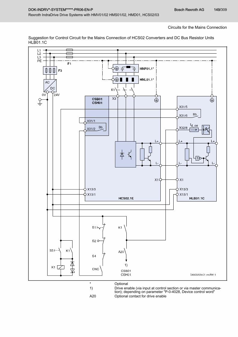
Suggestion for Control Circuit for the Mains Connection of HCS02 Converters and DC Bus Resistor UnitsHLB01.1C
* Optional1) Drive enable (via input at control section or via master communica‐
tion); depending on parameter "P-0-4028, Device control word"A20 Optional contact for drive enable
DOK-INDRV*-SYSTEM*****-PR06-EN-P Rexroth IndraDrive Drive Systems with HMV01/02 HMS01/02, HMD01, HCS02/03
Bosch Rexroth AG 149/309
Circuits for the Mains Connection

Bb Bb contact (see control section X31.1 and X31.2); Bb contact HLB01CNC Lag error message of control unitF1 Fuse of power supplyF3 Fuse of 24V power supply unitK1 External mains contactor (OFF delay must be smaller than td_on)S1 Emergency stopS2 Axis end positionS4 Power OffS5 Power Ontd_on Delay of input X32/8X1 Module busFig.9-4: Control Circuit for Mains Connection of HCS02 and HLB01.1C
Bosch Rexroth AG DOK-INDRV*-SYSTEM*****-PR06-EN-P Rexroth IndraDrive Drive Systems with HMV01/02 HMS01/02, HMD01, HCS02/03
150/309
Circuits for the Mains Connection

Suggestion for Control Circuit for the Mains Connection of HCS02 Converters and DC Bus Resistor UnitsHLB01.1C and Emergency Stop Relay
* Optional1) Drive enable (via input at control section or via master communica‐
tion); depending on parameter "P-0-4028, Device control word"A10 Emergency stop relay (example of circuit; optional design)
DOK-INDRV*-SYSTEM*****-PR06-EN-P Rexroth IndraDrive Drive Systems with HMV01/02 HMS01/02, HMD01, HCS02/03
Bosch Rexroth AG 151/309
Circuits for the Mains Connection

Bb Bb contact (see control section X31.1 and X31.2); Bb contact HLB01CNC Lag error message of control unitF1 Fuse of power supplyF3 Fuse of 24V power supply unitK1 External mains contactor (OFF delay must be smaller than td_on)S1 Emergency stopS2 Axis end positionS4 Power OffS5 Power Ontd_on Delay of input X32/8X1 Module busFig.9-5: Control Circuit for Mains Connection of HCS02 and HLB01.1C and
Emergency Stop Relay
Bosch Rexroth AG DOK-INDRV*-SYSTEM*****-PR06-EN-P Rexroth IndraDrive Drive Systems with HMV01/02 HMS01/02, HMD01, HCS02/03
152/309
Circuits for the Mains Connection

Suggestion for Control Circuit for the Mains Connection of HCS03 Converters and DC Bus Resistor UnitsHLB01.1D
* Optional; alternatively HNK011) Drive enable (via input at control section or via master communica‐
tion); depending on parameter "P-0-4028, Device control word"A20 Optional contact for drive enable
DOK-INDRV*-SYSTEM*****-PR06-EN-P Rexroth IndraDrive Drive Systems with HMV01/02 HMS01/02, HMD01, HCS02/03
Bosch Rexroth AG 153/309
Circuits for the Mains Connection

Bb Bb contact (see control section X31.1 and X31.2); Bb contact HLB01CNC Lag error message of control unitF1 Fuse of power supplyF3 Fuse of 24V power supply unitK1 External mains contactor (OFF delay must be smaller than td_on)S1 Emergency stopS2 Axis end positionS4 Power OffS5 Power Ontd_on Delay of input X32/8X1 Module busFig.9-6: Control Circuit for Mains Connection of HCS03 and HLB01.1D
9.4 Circuits for Mains Connection of Rexroth IndraDrive M Sup‐ply Units
9.4.1 General Information
Damage to the supply unit!NOTICEAt HMV01.1R supply units, there must be at least 10 ms between the requestmains OFF (signal at X32.6 / X32.7) and the disconnection of the mains volt‐age, so that the energy flow has been interrupted when the disconnectionprocess starts.You can make sure this order is observed by appropriate switch elements(e.g. by a main switch of the control cabinet with leading auxiliary contact).For this purpose, connect the auxiliary contact in series with mains OFF.
Do not switch on HMV supply units simultaneously!In the switch-on sequence of the supply unit, the supplying mainsis loaded with the current IL_trans_max_on for the purpose of analysis.During the unloading process, voltage overshoot can occur at themains components connected in the incoming circuit (e.g. mainsfilters) due to inductances connected in the incoming circuit, e.g.the leakage inductance of the mains transformer.With 3 or more HMV supply units at the common supply mains:Switch on supply units one after the other with a time interval of atleast 0.5 seconds so that the inrush currents are not added.
Control Circuits HMV For HMV01.1E, HMV01.1R and HMV02.1R supply units, the following controlcircuits for the mains connection are described:● Control circuit for parallel operation HMV01.1E master-slave● Deceleration in the case of disturbed electronic system of drive● Deceleration in the case of emergency stop or mains failure● Control by emergency stop relay with DC bus short circuit● Control by emergency stop relay without DC bus short circuit● Control by control unit● Combination with DC bus resistor unit HLB01.1D
Bosch Rexroth AG DOK-INDRV*-SYSTEM*****-PR06-EN-P Rexroth IndraDrive Drive Systems with HMV01/02 HMS01/02, HMD01, HCS02/03
154/309
Circuits for the Mains Connection

9.4.2 Parallel Operation HMV01For the type of mains connection "group supply with DC bus connection", usethe control circuit master-slave when using HMV01.1E supply units. See theblock diagram below:Control Circuit for Parallel Operation HMV01.1E Master-Slave
1) Braking resistor switch-on threshold activatedFig.9-7: Block Diagram Control Circuit Master-Slave for Parallel Operation
HMV01.1E
9.4.3 Deceleration in the Case of Disturbed Electronic System of Drive (DCBus Short Circuit is Activated)
General InformationDC Bus Short Circuit ZKS If the electronic system of the drive is disturbed, motors can coast in an un‐
controlled way. In these cases, it is possible to short-circuit the DC bus volt‐age as a measure in addition to shutdown with deceleration of the drives incase the electronic system is disturbed.In HMV supply units (exception: HMV01.1R-W0120), a circuit has been inte‐grated which can discharge the DC bus as quickly as possible to low voltage.This circuit is called DC bus short circuit (ZKS). With active DC bus short cir‐cuit, a low-impedance resistor is connected to the DC bus between L+ and L-via a wear-free switch.
DOK-INDRV*-SYSTEM*****-PR06-EN-P Rexroth IndraDrive Drive Systems with HMV01/02 HMS01/02, HMD01, HCS02/03
Bosch Rexroth AG 155/309
Circuits for the Mains Connection

Risk of fire caused by the "sacrificing behav‐ior" of the ZKS stage!
NOTICE
The "ZKS" input activates the "DC bus short circuit" function, when the 24Vcontrol voltage has not been applied and when there isn't any current flowingto the input. This condition can occur in the following situations:● Failure of 24V control voltage● Wire break● Activation of serially connected contacts (e.g. axis limit switches)If the kinetic energy of the mechanical axis system regenerated when brakingis greater than the energy absorption capacity of HLB, the HLB device re‐mains active when braking via ZKS takes place, until it is thermally destroyed(sacrificing behavior). Risk of fire! In this case, braking via ZKS may onlycome into effect in the case of an emergency (e.g. activation of an axis limitswitch causes the mains supply to be cut off and simultaneously causes the24V supply of the ZKS input to be interrupted).Install a 24V UPS, if the "sacrificing behavior" of HLB is relevant to your drivesystem in the case of an emergency. This prevents the braking via ZKSwhich causes HLB to be destroyed due to the failure of the 24V control volt‐age. Braking via ZKS then will only take place in cases of emergency.
Type of motor and DC bus short circuitAsynchronous drives do not decelerate when the DC bus voltagehas been short-circuited!When the DC bus has been short-circuited, motors with perma‐nent magnet excitation generate braking torque and are deceler‐ated.
Bosch Rexroth AG DOK-INDRV*-SYSTEM*****-PR06-EN-P Rexroth IndraDrive Drive Systems with HMV01/02 HMS01/02, HMD01, HCS02/03
156/309
Circuits for the Mains Connection

Control Circuits With DC Bus Short Circuit (ZKS)If you control the mains contactor in the supply unit by an emergency stop re‐lay and short-circuit the DC bus, you achieve a high degree of safety with lit‐tle effort. The monitoring functions of the drive system are then used in themost effective way.
DC bus short circuit at HMV without integrated circuit for DC busshort circuitUse HLB01 DC bus resistor units for DC bus short circuit.It is not recommended to short-circuit the motor connections.
Application Use this variant, when● only motors with permanent magnet excitation are connected● motors with permanent magnet excitation and asynchronous motors (in‐
duction machines) are connected● the emergency stop switch has to be duplicated or a safety door moni‐
tor, for example, is required● your drive system has an extensive emergency stop circuit
Maximum resistance of control circuitThe pickup current of the auxiliary relay for control of the mainscontactor flows via the emergency stop circuit. In order that themains contactor picks up reliably, the total resistance of the emer‐gency stop circuit taking effect between connections X32/1 andX32/9 has to be less than 45 Ω!
Features Due to the DC bus short circuit, motors with permanent magnet excitationcan be shutdown with deceleration even if the electronic system of the driveis disturbed. In order to trigger a DC bus short circuit in such a case, the Bbcontacts of the drive controllers have to be connected in series with the con‐trol contact and wired in the emergency stop circuit. The DC bus short circuitonly takes effect in the case of drive failure. If emergency stop is actuated,asynchronous drives therefore are braking, too.When the Bb contacts of the supply unit are connected in series with the con‐trol contact in the emergency stop circuit, the DC bus short circuit is only trig‐gered in the case of a supply unit error.In the case of emergency stop or when the monitors of the supply unit trigger(e.g. mains failure), the electronic system of the drives shuts them down ac‐cording to the error reaction that was set.
Personal injury caused by uncontrolled axismotion!
WARNING
The circuit for DC bus short circuit protects machines in the case of drive er‐rors. By itself it cannot assume the function of personal protection. In thecase of errors in the drive and supply unit, uncontrolled drive motion can oc‐cur even when the DC bus short circuit has been activated.Asynchronous machines do not brake when the DC bus has been short-circuited. Personal injury can occur according to the machine design.Use additional monitors and protective devices on the installation side.Use the "Integrated Safety Technology" by Rexroth.
DOK-INDRV*-SYSTEM*****-PR06-EN-P Rexroth IndraDrive Drive Systems with HMV01/02 HMS01/02, HMD01, HCS02/03
Bosch Rexroth AG 157/309
Circuits for the Mains Connection

Operating Principle When the emergency stop pushbutton is actuated, the mains contactor in thesupply unit opens. The emergency stop relay or an auxiliary contact of themains contactor switches off the drive enable signals. The drives are shutdown according to the error reaction set in the drive controller.The mains contactor is switched off and the DC bus short circuit (ZKS) takeseffect, when● the supply unit (Bb1 contact) outputs a drive error message● the control unit (CNC contact) outputs an error message● the limit switch (S2) is passed
Bosch Rexroth AG DOK-INDRV*-SYSTEM*****-PR06-EN-P Rexroth IndraDrive Drive Systems with HMV01/02 HMS01/02, HMD01, HCS02/03
158/309
Circuits for the Mains Connection

Control Circuit "DC Bus Short Circuit (ZKS) in the Case of Disturbed Electronic System of Drive" for the MainsConnection of HMV01.1E Supply Units With Integrated Mains Contactor (e.g. HMV01.1E-W0030, -W0070, -W0120)
F1 Fuse of power supplyF3 Fuse of 24V power supply unit1) Control of K1, if A10 is not used
DOK-INDRV*-SYSTEM*****-PR06-EN-P Rexroth IndraDrive Drive Systems with HMV01/02 HMS01/02, HMD01, HCS02/03
Bosch Rexroth AG 159/309
Circuits for the Mains Connection

2) Drive enable (via input at control section or via master communica‐tion); see also parameter "P-0-4028, Device control word"
A10 Emergency stop relay (example of circuit)Bb1 Readiness for operation of supply unitBb Readiness for operation of drive controllers (see control section X31.1
and X31.2)CNC Lag error message of control unitK1 Integrated mains contactorK4 Control of drive enableS1 Emergency stopS2 Axis end positionS4 Power OffS5 Power OnS11, S12 Safety door monitorZKS DC bus short circuitHNL, HNF Optional, depending on the applicationFig.9-8: Control Circuit DC Bus Short Circuit (ZKS) in the Case of Disturbed
Electronic System of Drive for HMV01.1E Supply Units With Integra‐ted Mains Contactor
Bosch Rexroth AG DOK-INDRV*-SYSTEM*****-PR06-EN-P Rexroth IndraDrive Drive Systems with HMV01/02 HMS01/02, HMD01, HCS02/03
160/309
Circuits for the Mains Connection
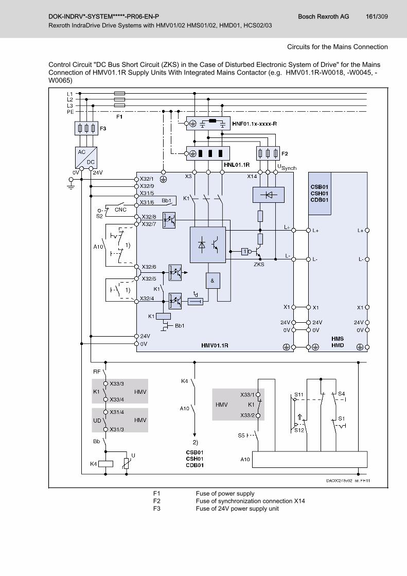
Control Circuit "DC Bus Short Circuit (ZKS) in the Case of Disturbed Electronic System of Drive" for the MainsConnection of HMV01.1R Supply Units With Integrated Mains Contactor (e.g. HMV01.1R-W0018, -W0045, -W0065)
F1 Fuse of power supplyF2 Fuse of synchronization connection X14F3 Fuse of 24V power supply unit
DOK-INDRV*-SYSTEM*****-PR06-EN-P Rexroth IndraDrive Drive Systems with HMV01/02 HMS01/02, HMD01, HCS02/03
Bosch Rexroth AG 161/309
Circuits for the Mains Connection

1) Control of K1, if A10 is not used2) Drive enable (via input at control section or via master communica‐
tion); see also parameter "P-0-4028, Device control word"A10 Emergency stop relay (example of circuit)Bb1 Readiness for operation of supply unitBb Readiness for operation of drive controllers (see control section X31.1
and X31.2)CNC Lag error message of control unitK1 Integrated mains contactorK4 Control of drive enableS1 Emergency stopS2 Axis end positionS4 Power OffS5 Power OnS11, S12 Safety door monitorZKS DC bus short circuitFig.9-9: Control Circuit DC Bus Short Circuit (ZKS) in the Case of Disturbed
Electronic System of Drive for HMV01.1R Supply Units With Integra‐ted Mains Contactor
Operating Principle With
HLB01.1DWhen the emergency stop pushbutton is actuated, the mains contactor in thesupply unit drops out. The emergency stop relay or an auxiliary contact of themains contactor switches off the drive enable signals. The drives are shutdown according to the error reaction set in the drive controller.The mains contactor is switched off and the DC bus short circuit (ZKS) takeseffect in HMV and HLB, when● the supply unit (Bb1 contact) outputs a drive error message● the control unit (CNC contact) outputs an error message● the limit switch (S2) is passed
Risk of damage to the device!NOTICEEstablish connection from HMV_X32/8 to HLB_X32/7.This avoids energy from the mains connection being supplied and the DCbus short circuit protection device of the DC bus resistor unit HLB being si‐multaneously active.
Bosch Rexroth AG DOK-INDRV*-SYSTEM*****-PR06-EN-P Rexroth IndraDrive Drive Systems with HMV01/02 HMS01/02, HMD01, HCS02/03
162/309
Circuits for the Mains Connection
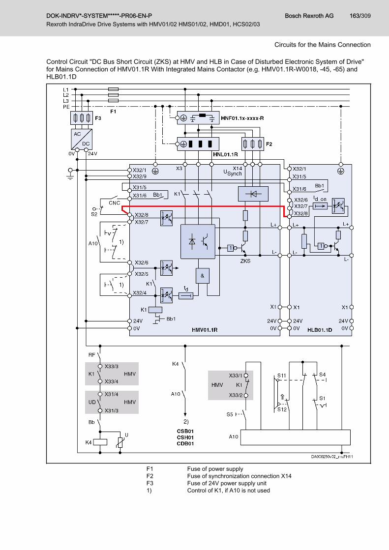
Control Circuit "DC Bus Short Circuit (ZKS) at HMV and HLB in Case of Disturbed Electronic System of Drive"for Mains Connection of HMV01.1R With Integrated Mains Contactor (e.g. HMV01.1R-W0018, -45, -65) andHLB01.1D
F1 Fuse of power supplyF2 Fuse of synchronization connection X14F3 Fuse of 24V power supply unit1) Control of K1, if A10 is not used
DOK-INDRV*-SYSTEM*****-PR06-EN-P Rexroth IndraDrive Drive Systems with HMV01/02 HMS01/02, HMD01, HCS02/03
Bosch Rexroth AG 163/309
Circuits for the Mains Connection

2) Drive enable (via input at control section or via master communica‐tion); see also parameter "P-0-4028, Device control word"
A10 Emergency stop relay (example of circuit)Bb1 Readiness for operation of supply unitBb Readiness for operation of drive controllers (see control section X31.1
and X31.2)CNC Lag error message of control unitK1 Integrated mains contactorK4 Control of drive enableS1 Emergency stopS2 Axis end positionS4 Power OffS5 Power OnS11, S12 Safety door monitorZKS DC bus short circuitFig.9-10: Control Circuit DC Bus Short Circuit (ZKS) at HMV and HLB in the
Case of Disturbed Electronic System of Drive for HMV01.1R SupplyUnits With Integrated Mains Contactor and HLB01.1D
Bosch Rexroth AG DOK-INDRV*-SYSTEM*****-PR06-EN-P Rexroth IndraDrive Drive Systems with HMV01/02 HMS01/02, HMD01, HCS02/03
164/309
Circuits for the Mains Connection

Suggestion for Control Circuit "HMV and HLB With DC Bus Short Circuit (ZKS) in Case of Disturbed ElectronicSystem of Drive" for Mains Connection of HMV01.1R-W0120 With External Mains Contactor and HLB01.1D
1) Control of K1, if A10 is not used2) Drive enable (via input at control section or via master communica‐
tion); depending on parameter "P-0-4028, Device control word"A10 Emergency stop relay (example of circuit; optional design)
DOK-INDRV*-SYSTEM*****-PR06-EN-P Rexroth IndraDrive Drive Systems with HMV01/02 HMS01/02, HMD01, HCS02/03
Bosch Rexroth AG 165/309
Circuits for the Mains Connection
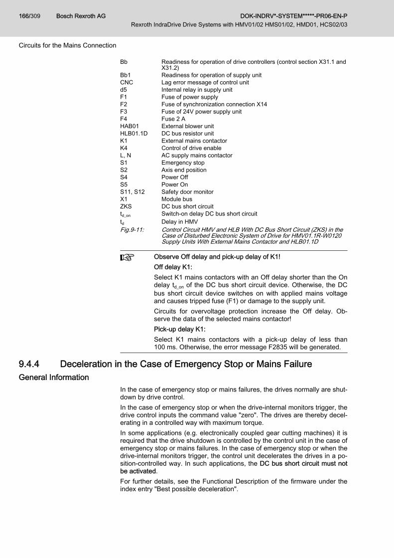
Bb Readiness for operation of drive controllers (control section X31.1 andX31.2)
Bb1 Readiness for operation of supply unitCNC Lag error message of control unitd5 Internal relay in supply unitF1 Fuse of power supplyF2 Fuse of synchronization connection X14F3 Fuse of 24V power supply unitF4 Fuse 2 AHAB01 External blower unitHLB01.1D DC bus resistor unitK1 External mains contactorK4 Control of drive enableL, N AC supply mains contactorS1 Emergency stopS2 Axis end positionS4 Power OffS5 Power OnS11, S12 Safety door monitorX1 Module busZKS DC bus short circuittd_on Switch-on delay DC bus short circuittd Delay in HMVFig.9-11: Control Circuit HMV and HLB With DC Bus Short Circuit (ZKS) in the
Case of Disturbed Electronic System of Drive for HMV01.1R-W0120Supply Units With External Mains Contactor and HLB01.1D
Observe Off delay and pick-up delay of K1!Off delay K1:Select K1 mains contactors with an Off delay shorter than the Ondelay td_on of the DC bus short circuit device. Otherwise, the DCbus short circuit device switches on with applied mains voltageand causes tripped fuse (F1) or damage to the supply unit.Circuits for overvoltage protection increase the Off delay. Ob‐serve the data of the selected mains contactor!Pick-up delay K1:Select K1 mains contactors with a pick-up delay of less than100 ms. Otherwise, the error message F2835 will be generated.
9.4.4 Deceleration in the Case of Emergency Stop or Mains FailureGeneral Information
In the case of emergency stop or mains failures, the drives normally are shut‐down by drive control.In the case of emergency stop or when the drive-internal monitors trigger, thedrive control inputs the command value "zero". The drives are thereby decel‐erating in a controlled way with maximum torque.In some applications (e.g. electronically coupled gear cutting machines) it isrequired that the drive shutdown is controlled by the control unit in the case ofemergency stop or mains failures. In the case of emergency stop or when thedrive-internal monitors trigger, the control unit decelerates the drives in a po‐sition-controlled way. In such applications, the DC bus short circuit must notbe activated.For further details, see the Functional Description of the firmware under theindex entry "Best possible deceleration".
Bosch Rexroth AG DOK-INDRV*-SYSTEM*****-PR06-EN-P Rexroth IndraDrive Drive Systems with HMV01/02 HMS01/02, HMD01, HCS02/03
166/309
Circuits for the Mains Connection
Control Circuit "Position-Controlled Deceleration by the Control Unit" without DC Bus ShortCircuit (ZKS)
If the mains contactor is controlled by the control unit, the drive, in the case ofemergency stop or when the drive-internal monitor triggers, can be deceler‐ated in a position-controlled way by a control unit.
Application This kind of mains contactor control is mainly used for electronically coupleddrives that are decelerated synchronously even in the case of mains failure.
Features The DC bus voltage is not short-circuited so that there is energy available forposition-controlled deceleration of the drives.
The energy stored in the DC bus or the regenerated energy hasto be greater than the energy required for excitation of asynchro‐nous machines or for return motions.
The parameter "Activation of NC reaction on error" has to be set accordinglyin the drive controller (P-0-0117, bit 0 = 1).In the case of emergency stop or when the monitors of the supply unit trigger(e.g. mains failure), the drives are decelerated in a position-controlled way bythe positioning control.
Operating Principle When the emergency stop circuit opens or the monitors of the supply unittrigger (e.g. mains failure), the mains contactor in the supply unit drops out.For drives with sercos interface, the error is signaled to the control unit andthe drives can be decelerated in a position-controlled way.For drives without sercos interface, the control unit has to evaluate the UDcontact. When the UD contact triggers, the control unit must decelerate thedrives.
Damage to machines caused by unbrakedcoasting to stop of the drives in case DC busvoltage is too low!
NOTICE
The control unit should evaluate the UD contact and decelerate the driveswhen the contact triggers.
DOK-INDRV*-SYSTEM*****-PR06-EN-P Rexroth IndraDrive Drive Systems with HMV01/02 HMS01/02, HMD01, HCS02/03
Bosch Rexroth AG 167/309
Circuits for the Mains Connection
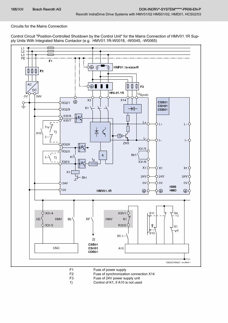
Control Circuit "Position-Controlled Shutdown by the Control Unit" for the Mains Connection of HMV01.1R Sup‐ply Units With Integrated Mains Contactor (e.g. HMV01.1R-W0018, -W0045, -W0065)
F1 Fuse of power supplyF2 Fuse of synchronization connection X14F3 Fuse of 24V power supply unit1) Control of K1, if A10 is not used
Bosch Rexroth AG DOK-INDRV*-SYSTEM*****-PR06-EN-P Rexroth IndraDrive Drive Systems with HMV01/02 HMS01/02, HMD01, HCS02/03
168/309
Circuits for the Mains Connection

2) Drive enable (via input at control section or via master communica‐tion); see also parameter "P-0-4028, Device control word"
A10 Emergency stop relay (example of circuit)Bb1 Readiness for operation of supply unitBb Readiness for operation of drive controllers (see control section X31.1
and X31.2)CNC Control unit of installationK1 Integrated mains contactorK4 Control of drive enableS1 Emergency stopS2 Axis end positionS4 Power OffS5 Power OnS11, S12 Safety door monitorZKS DC bus short circuitFig.9-12: Control Circuit Without DC Bus Short Circuit (ZKS), Position-Control‐
led Shutdown by the Control Unit for HMV01.1R Supply Units With In‐tegrated Mains Contactor
Control Circuit Emergency Stop Relay without DC Bus Short Circuit (ZKS) Application ● If unbraked coasting to stop of the drives does not damage the installa‐
tion.● If only asynchronous motors are connected to the supply unit.● If the end positions of the feed axes have been sufficiently cushioned.● If external braking devices are used.
Features The DC bus voltage is not short-circuited.In the case of emergency stop or when the monitors of the supply unit trigger(e.g. mains failure), the drives are shut down according to the error reactionset in the drive controller.
Operating Principle When the emergency stop circuit opens, the mains contactor in the supplyunit drops out immediately. The emergency stop relay or an auxiliary contactof the mains contactor switches off the drive enable signals. The drives areshut down according to the error reaction set in the drive controller.
Damage to machines caused by unbrakedcoasting to stop of the drives in case theirelectronic system is disturbed!
NOTICE
Use motors with mechanical brake (a holding brake mustn't be used as serv‐ice brake).Sufficiently cushion end positions of feed axes.
DOK-INDRV*-SYSTEM*****-PR06-EN-P Rexroth IndraDrive Drive Systems with HMV01/02 HMS01/02, HMD01, HCS02/03
Bosch Rexroth AG 169/309
Circuits for the Mains Connection

Example Control Circuit "Without DC Bus Short Circuit (ZKS)" for the Mains Connection of HMV01.1E SupplyUnits With Integrated Mains Contactor (e.g. HMV01.1E-W0030, -W0070, -W0120)
F1 Fuse of power supplyF3 Fuse of 24V power supply unit1) Control of K1, if A10 is not used
Bosch Rexroth AG DOK-INDRV*-SYSTEM*****-PR06-EN-P Rexroth IndraDrive Drive Systems with HMV01/02 HMS01/02, HMD01, HCS02/03
170/309
Circuits for the Mains Connection

2) Drive enable (via input at control section or via master communica‐tion); see also parameter "P-0-4028, Device control word"
A10 Emergency stop relay (example of circuit)Bb1 Readiness for operation of supply unitBb Readiness for operation of drive controllers (see control section X31.1
and X31.2)K1 Integrated mains contactorK4 Control of drive enableS1 Emergency stopS4 Power OffS5 Power OnS11, S12 Safety door monitorZKS DC bus short circuitHNL, HNF Optional, depending on the applicationFig.9-13: Control Circuit Without DC Bus Short Circuit (ZKS) for HMV01.1E
Supply Units With Integrated Mains Contactor
DOK-INDRV*-SYSTEM*****-PR06-EN-P Rexroth IndraDrive Drive Systems with HMV01/02 HMS01/02, HMD01, HCS02/03
Bosch Rexroth AG 171/309
Circuits for the Mains Connection
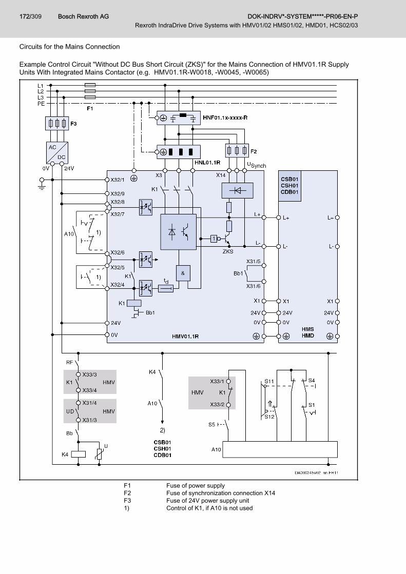
Example Control Circuit "Without DC Bus Short Circuit (ZKS)" for the Mains Connection of HMV01.1R SupplyUnits With Integrated Mains Contactor (e.g. HMV01.1R-W0018, ‑W0045, ‑W0065)
F1 Fuse of power supplyF2 Fuse of synchronization connection X14F3 Fuse of 24V power supply unit1) Control of K1, if A10 is not used
Bosch Rexroth AG DOK-INDRV*-SYSTEM*****-PR06-EN-P Rexroth IndraDrive Drive Systems with HMV01/02 HMS01/02, HMD01, HCS02/03
172/309
Circuits for the Mains Connection

2) Drive enable (via input at control section or via master communica‐tion); see parameter "P-0-4028, Device control word"
A10 Emergency stop relay (example of circuit)Bb1 Readiness for operation of supply unitBb Readiness for operation of drive controllers (see control section X31.1
and X31.2)K1 Integrated mains contactorK4 Control of drive enableS1 Emergency stopS4 Power OffS5 Power OnS11, S12 Safety door monitorZKS DC bus short circuitFig.9-14: Control Circuit Without DC Bus Short Circuit (ZKS) for HMV01.1R
Supply Units With Integrated Mains Contactor
DOK-INDRV*-SYSTEM*****-PR06-EN-P Rexroth IndraDrive Drive Systems with HMV01/02 HMS01/02, HMD01, HCS02/03
Bosch Rexroth AG 173/309
Circuits for the Mains Connection

Example Control Circuit "Without DC Bus Short Circuit (ZKS)" for the Mains Connection of HMV01.1R SupplyUnits Without Integrated Mains Contactor (e.g. HMV01.1R-W0120)
F1 Fuse of power supplyF2 Fuse of synchronization connection X14 (see Project Planning Manual
"Rexroth IndraDrive Supply Units and Power Sections")F3 Fuse of 24V power supply unit
Bosch Rexroth AG DOK-INDRV*-SYSTEM*****-PR06-EN-P Rexroth IndraDrive Drive Systems with HMV01/02 HMS01/02, HMD01, HCS02/03
174/309
Circuits for the Mains Connection
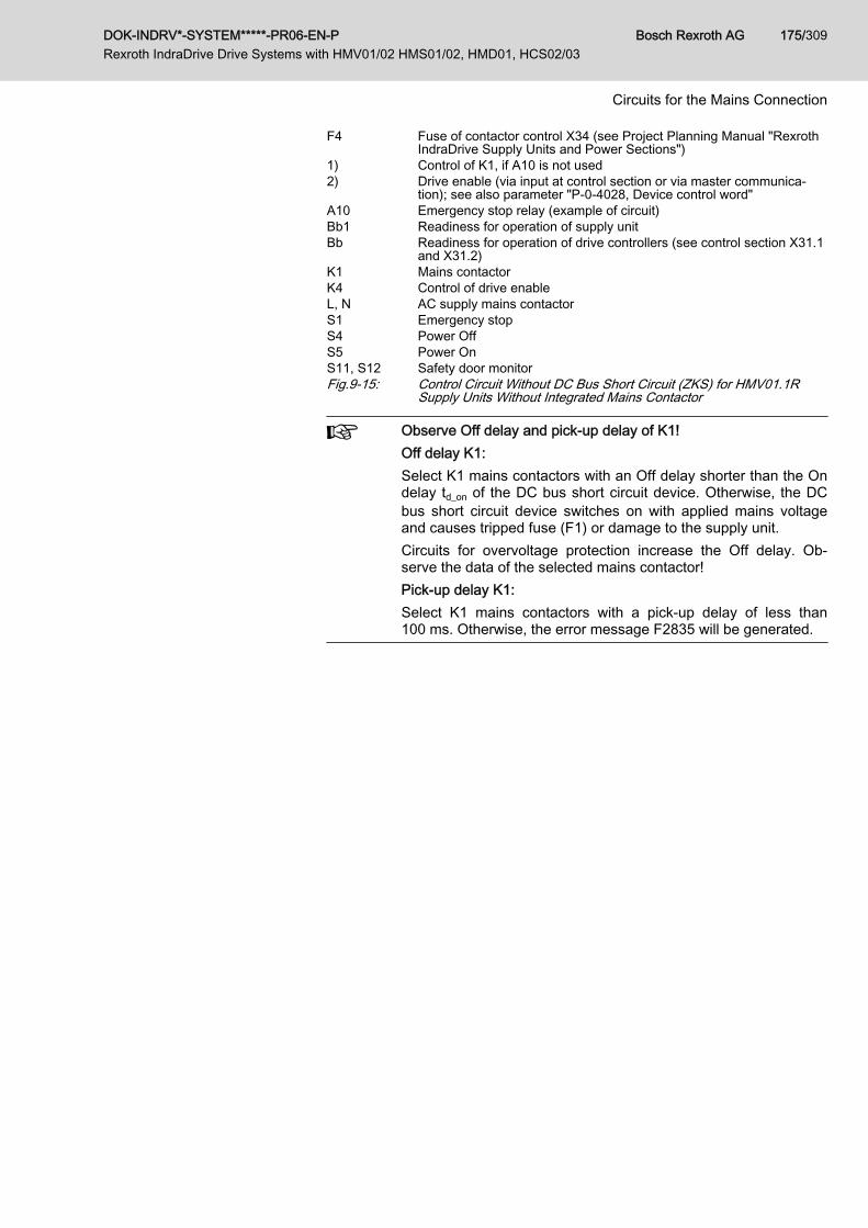
F4 Fuse of contactor control X34 (see Project Planning Manual "RexrothIndraDrive Supply Units and Power Sections")
1) Control of K1, if A10 is not used2) Drive enable (via input at control section or via master communica‐
tion); see also parameter "P-0-4028, Device control word"A10 Emergency stop relay (example of circuit)Bb1 Readiness for operation of supply unitBb Readiness for operation of drive controllers (see control section X31.1
and X31.2)K1 Mains contactorK4 Control of drive enableL, N AC supply mains contactorS1 Emergency stopS4 Power OffS5 Power OnS11, S12 Safety door monitorFig.9-15: Control Circuit Without DC Bus Short Circuit (ZKS) for HMV01.1R
Supply Units Without Integrated Mains Contactor
Observe Off delay and pick-up delay of K1!Off delay K1:Select K1 mains contactors with an Off delay shorter than the Ondelay td_on of the DC bus short circuit device. Otherwise, the DCbus short circuit device switches on with applied mains voltageand causes tripped fuse (F1) or damage to the supply unit.Circuits for overvoltage protection increase the Off delay. Ob‐serve the data of the selected mains contactor!Pick-up delay K1:Select K1 mains contactors with a pick-up delay of less than100 ms. Otherwise, the error message F2835 will be generated.
DOK-INDRV*-SYSTEM*****-PR06-EN-P Rexroth IndraDrive Drive Systems with HMV01/02 HMS01/02, HMD01, HCS02/03
Bosch Rexroth AG 175/309
Circuits for the Mains Connection
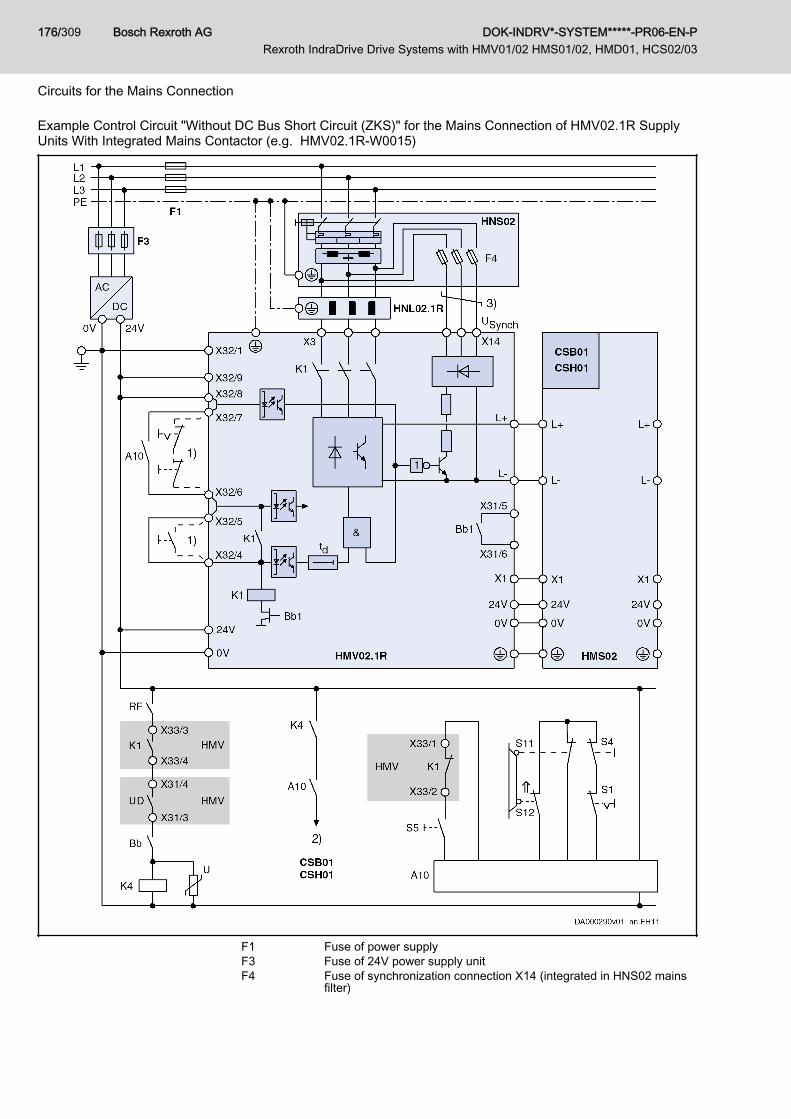
Example Control Circuit "Without DC Bus Short Circuit (ZKS)" for the Mains Connection of HMV02.1R SupplyUnits With Integrated Mains Contactor (e.g. HMV02.1R-W0015)
F1 Fuse of power supplyF3 Fuse of 24V power supply unitF4 Fuse of synchronization connection X14 (integrated in HNS02 mains
filter)
Bosch Rexroth AG DOK-INDRV*-SYSTEM*****-PR06-EN-P Rexroth IndraDrive Drive Systems with HMV01/02 HMS01/02, HMD01, HCS02/03
176/309
Circuits for the Mains Connection

1) Control of K1, if A10 is not used2) Drive enable (via input at control section or via master communica‐
tion); see parameter "P-0-4028, Device control word"3) Twist wiresA10 Emergency stop relay (example of circuit)Bb1 Readiness for operation of supply unitBb Readiness for operation of drive controllers (see control section X31.1
and X31.2)K1 Integrated mains contactorK4 Control of drive enableS1 Emergency stopS4 Power OffS5 Power OnS11, S12 Safety door monitorZKS DC bus short circuitFig.9-16: Control Circuit Without DC Bus Short Circuit (ZKS) for HMV02.1R
Supply Units With Integrated Mains Contactor
9.4.5 Signal Sequences When Switching HMV Supply Units ON and OFFSwitching On
Risk of damage to the supply units when theyare switched on simultaneously!
NOTICE
With 3 or more HMV supply units at common supply mains: Switch on supplyunits one after the other with a time interval of at least 0.5 seconds so thatthe inrush currents are not added.In the switch-on sequence of the supply unit, the supplying mains is loadedwith the current IL_trans_max_on for the purpose of analysis. During the unloadingprocess, voltage overshoot can occur at the mains components connected inthe incoming circuit (e.g. mains filters) due to inductances connected in theincoming circuit, e.g. the leakage inductance of the mains transformer.
DOK-INDRV*-SYSTEM*****-PR06-EN-P Rexroth IndraDrive Drive Systems with HMV01/02 HMS01/02, HMD01, HCS02/03
Bosch Rexroth AG 177/309
Circuits for the Mains Connection
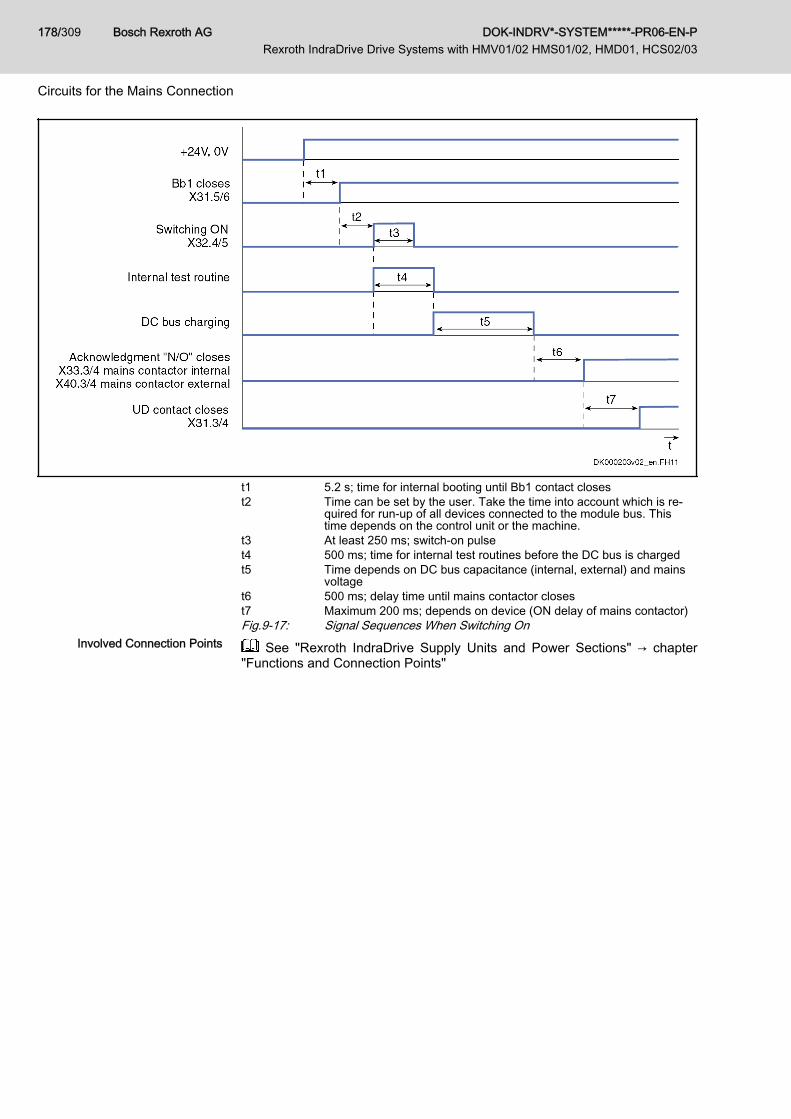
t1 5.2 s; time for internal booting until Bb1 contact closest2 Time can be set by the user. Take the time into account which is re‐
quired for run-up of all devices connected to the module bus. Thistime depends on the control unit or the machine.
t3 At least 250 ms; switch-on pulset4 500 ms; time for internal test routines before the DC bus is chargedt5 Time depends on DC bus capacitance (internal, external) and mains
voltaget6 500 ms; delay time until mains contactor closest7 Maximum 200 ms; depends on device (ON delay of mains contactor)Fig.9-17: Signal Sequences When Switching On
Involved Connection Points See "Rexroth IndraDrive Supply Units and Power Sections" → chapter"Functions and Connection Points"
Bosch Rexroth AG DOK-INDRV*-SYSTEM*****-PR06-EN-P Rexroth IndraDrive Drive Systems with HMV01/02 HMS01/02, HMD01, HCS02/03
178/309
Circuits for the Mains Connection
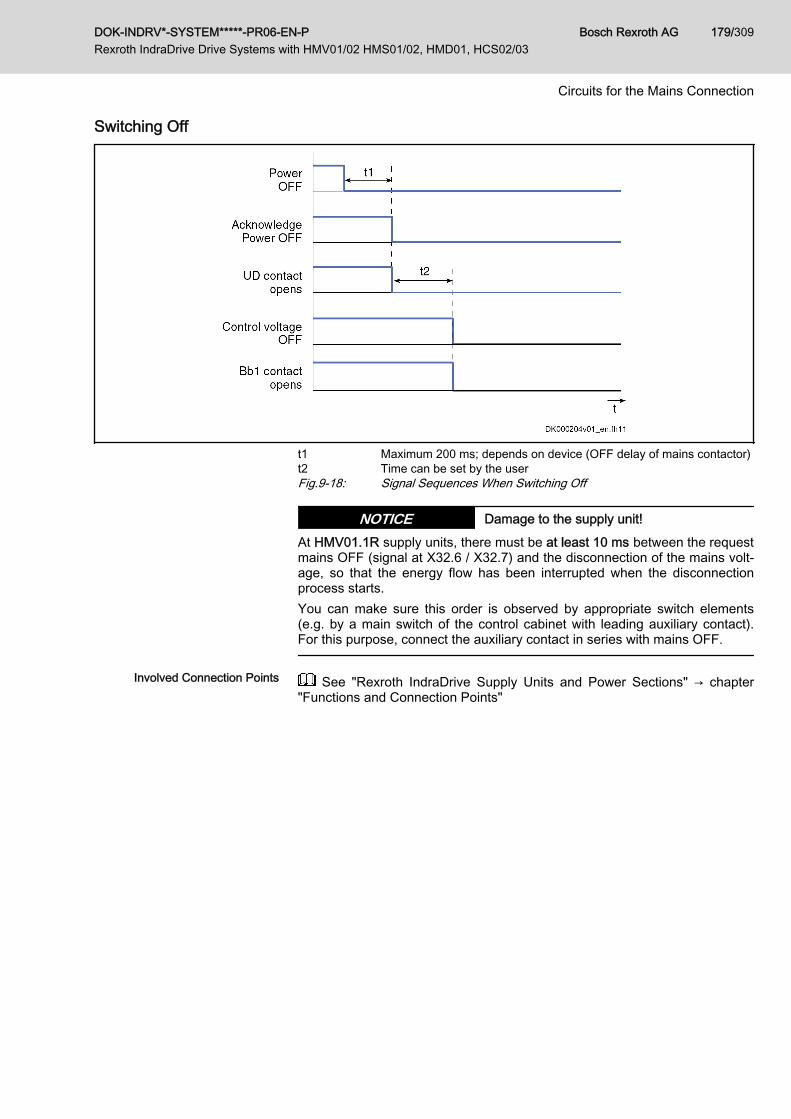
Switching Off
t1 Maximum 200 ms; depends on device (OFF delay of mains contactor)t2 Time can be set by the userFig.9-18: Signal Sequences When Switching Off
Damage to the supply unit!NOTICEAt HMV01.1R supply units, there must be at least 10 ms between the requestmains OFF (signal at X32.6 / X32.7) and the disconnection of the mains volt‐age, so that the energy flow has been interrupted when the disconnectionprocess starts.You can make sure this order is observed by appropriate switch elements(e.g. by a main switch of the control cabinet with leading auxiliary contact).For this purpose, connect the auxiliary contact in series with mains OFF.
Involved Connection Points See "Rexroth IndraDrive Supply Units and Power Sections" → chapter"Functions and Connection Points"
DOK-INDRV*-SYSTEM*****-PR06-EN-P Rexroth IndraDrive Drive Systems with HMV01/02 HMS01/02, HMD01, HCS02/03
Bosch Rexroth AG 179/309
Circuits for the Mains Connection

Bosch Rexroth AG DOK-INDRV*-SYSTEM*****-PR06-EN-P Rexroth IndraDrive Drive Systems with HMV01/02 HMS01/02, HMD01, HCS02/03
180/309
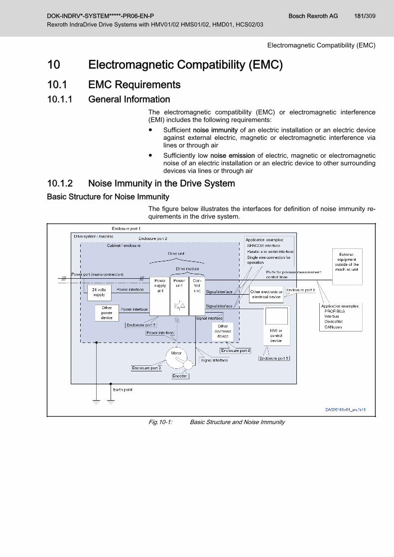
10 Electromagnetic Compatibility (EMC)10.1 EMC Requirements10.1.1 General Information
The electromagnetic compatibility (EMC) or electromagnetic interference(EMI) includes the following requirements:● Sufficient noise immunity of an electric installation or an electric device
against external electric, magnetic or electromagnetic interference vialines or through air
● Sufficiently low noise emission of electric, magnetic or electromagneticnoise of an electric installation or an electric device to other surroundingdevices via lines or through air
10.1.2 Noise Immunity in the Drive SystemBasic Structure for Noise Immunity
The figure below illustrates the interfaces for definition of noise immunity re‐quirements in the drive system.
Fig.10-1: Basic Structure and Noise Immunity
DOK-INDRV*-SYSTEM*****-PR06-EN-P Rexroth IndraDrive Drive Systems with HMV01/02 HMS01/02, HMD01, HCS02/03
Bosch Rexroth AG 181/309
Electromagnetic Compatibility (EMC)

Limit Values for Noise Immunity
No Place of effect Phenom‐enon Standard Conditions Coupling
Test values accord‐ing standard EN
61800-3
Perform‐ance level
Enclosure port IEC 61000-4-2 CD, AD 6 kV CD, 8 kV AD, ifCD not possible B
RF Field IEC 61000-4-3 Via antenna onEUT 10 V / m A
Power port Burst IEC 61000-4-4 length > 3 m
mains connectionI < 100 A: discou‐
pling networkI > 100 A: clamp
4 kV / 2.5 kHz(clamp) B
Surge IEC 61000-4-5
Only mainsconnection;
I < 63 A,light load test
Line – line 1 kV(2 Ohm)
Line – earth 2 kV(12 Ohm)
B
IEC 61000-4-6 length > 3 m clamp 10 V, 0.15–80 MHz A
Power Interface Burst IEC 61000-4-4 length > 3 m clamp B
Signal Interface Burst IEC 61000-4-4 length > 3 m clamp B
IEC 61000-4-6 length > 3 m Clamp or CDN 10 V, 0.15–80 MHz B
Ports of process;
measurementcontrol lines
Burst IEC 61000-4-4 length > 3 m clamp B
IEC 61000-4-6 length > 3 m Clamp or CDN 10 V, 0.15–80 MHz A
Tab.10-1: Noise Immunity Limit Values
Evaluation Criterion Explanation (abbreviated form from EN61800-3)
A Deviations within allowed range
B Automatic recovery after interference
C Switched off without automatic recovery.Device remains undamaged.
Tab.10-2: Evaluation Criterion
10.1.3 Noise Emission of the Drive SystemCauses of Noise Emission
Controlled variable-speed drives contain converters containing snappy semi‐conductors. The advantage of modifying the speed with high precision is ach‐ieved by means of pulse width modulation of the converter voltage. This cangenerate sinusoidal currents with variable amplitude and frequency in themotor.The steep voltage rise, the high clock rate and the resulting harmonics causeunwanted but physically unavoidable emission of interference voltage and in‐terference fields (wide band interference). The interference mainly is asym‐metric interference against ground.The propagation of this interference strongly depends on:
Bosch Rexroth AG DOK-INDRV*-SYSTEM*****-PR06-EN-P Rexroth IndraDrive Drive Systems with HMV01/02 HMS01/02, HMD01, HCS02/03
182/309
Electromagnetic Compatibility (EMC)
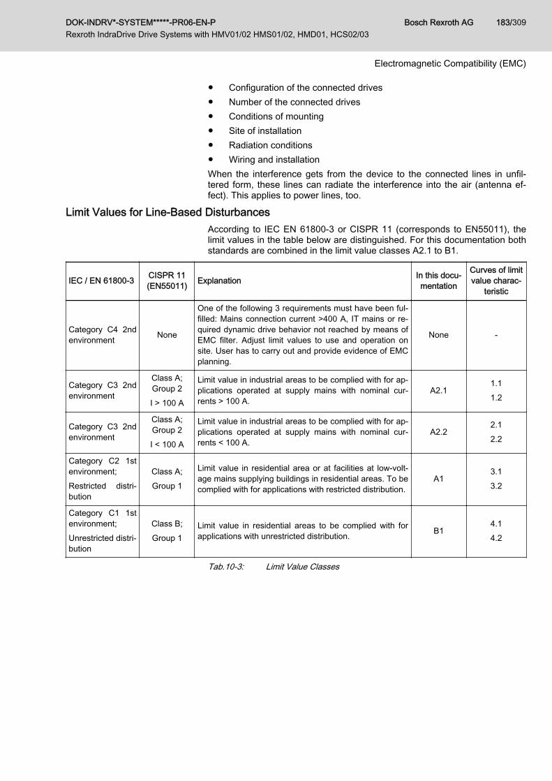
● Configuration of the connected drives● Number of the connected drives● Conditions of mounting● Site of installation● Radiation conditions● Wiring and installationWhen the interference gets from the device to the connected lines in unfil‐tered form, these lines can radiate the interference into the air (antenna ef‐fect). This applies to power lines, too.
Limit Values for Line-Based DisturbancesAccording to IEC EN 61800-3 or CISPR 11 (corresponds to EN55011), thelimit values in the table below are distinguished. For this documentation bothstandards are combined in the limit value classes A2.1 to B1.
IEC / EN 61800-3 CISPR 11(EN55011) Explanation In this docu‐
mentation
Curves of limitvalue charac‐
teristic
Category C4 2ndenvironment None
One of the following 3 requirements must have been ful‐filled: Mains connection current >400 A, IT mains or re‐quired dynamic drive behavior not reached by means ofEMC filter. Adjust limit values to use and operation onsite. User has to carry out and provide evidence of EMCplanning.
None -
Category C3 2ndenvironment
Class A;Group 2I > 100 A
Limit value in industrial areas to be complied with for ap‐plications operated at supply mains with nominal cur‐rents > 100 A.
A2.11.11.2
Category C3 2ndenvironment
Class A;Group 2I < 100 A
Limit value in industrial areas to be complied with for ap‐plications operated at supply mains with nominal cur‐rents < 100 A.
A2.22.12.2
Category C2 1stenvironment;Restricted distri‐bution
Class A;Group 1
Limit value in residential area or at facilities at low-volt‐age mains supplying buildings in residential areas. To becomplied with for applications with restricted distribution.
A13.13.2
Category C1 1stenvironment;Unrestricted distri‐bution
Class B;Group 1
Limit value in residential areas to be complied with forapplications with unrestricted distribution. B1
4.14.2
Tab.10-3: Limit Value Classes
DOK-INDRV*-SYSTEM*****-PR06-EN-P Rexroth IndraDrive Drive Systems with HMV01/02 HMS01/02, HMD01, HCS02/03
Bosch Rexroth AG 183/309
Electromagnetic Compatibility (EMC)
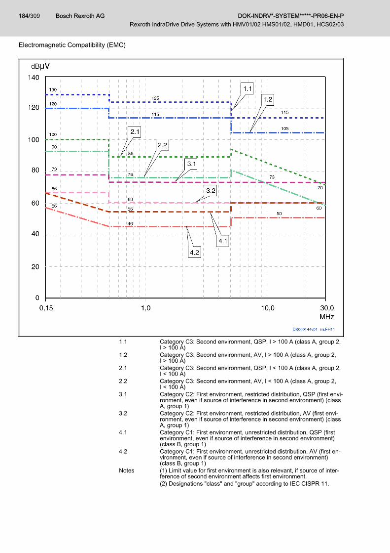
1.1 Category C3: Second environment, QSP, I > 100 A (class A, group 2,I > 100 A)
1.2 Category C3: Second environment, AV, I > 100 A (class A, group 2,I > 100 A)
2.1 Category C3: Second environment, QSP, I < 100 A (class A, group 2,I < 100 A)
2.2 Category C3: Second environment, AV, I < 100 A (class A, group 2,I < 100 A)
3.1 Category C2: First environment, restricted distribution, QSP (first envi‐ronment, even if source of interference in second environment) (classA, group 1)
3.2 Category C2: First environment, restricted distribution, AV (first envi‐ronment, even if source of interference in second environment) (classA, group 1)
4.1 Category C1: First environment, unrestricted distribution, QSP (firstenvironment, even if source of interference in second environment)(class B, group 1)
4.2 Category C1: First environment, unrestricted distribution, AV (first en‐vironment, even if source of interference in second environment)(class B, group 1)
Notes (1) Limit value for first environment is also relevant, if source of inter‐ference of second environment affects first environment.(2) Designations "class" and "group" according to IEC CISPR 11.
Bosch Rexroth AG DOK-INDRV*-SYSTEM*****-PR06-EN-P Rexroth IndraDrive Drive Systems with HMV01/02 HMS01/02, HMD01, HCS02/03
184/309
Electromagnetic Compatibility (EMC)

QSP: Measuring method quasi peak measurement; AV: Measuringmethod arithmetic averaging
Fig.10-2: Limit Values for Line-Based Disturbances (IEC 61800-3); Limit ValueCharacteristic through Frequency Range
Second Environment, IndustrialArea
Facilities not directly connected to a low-voltage mains to supply buildings inresidential areas.If the limit values in an industrial area separated from public supply by atransformer station only have to be complied with at the property boundary orin the neighboring low-voltage mains, the filter might not be necessary. In thevicinity of broadcast receivers or other sensitive devices as regards high-fre‐quency, such as measuring sensors, measuring lines or measuring devices,it is normally required to use the interference suppression filter.Increasing the noise immunity of a sensitive device can often be the econom‐ically better solution compared to measures of interference suppression atthe drive system of the installation.
First Environment Environment containing residential areas and facilities directly connected,without interstage transformer, to a low-voltage mains supplying buildings inresidential areas.Medium-sized manufacturing plants and industrial establishments can beconnected to the public low-voltage mains together with residential buildings.In this case, there is a high risk for radio and television reception if therearen't any measures for radio interference suppression taken. Therefore, theindicated measures are generally recommended.
Nominal Current of Supply Mains The nominal current of the supply mains (> 100 A or < 100 A) is specified bythe local power supply company at the connection point of the mains. For in‐dustrial companies, for example, such connection points are the interconnect‐ing stations from the power supply system.
Unrestricted Distribution Channel of distribution for which placing on the market is independent of theEMC expert knowledge of the customer or user of electric drives.
Restricted Distribution Channel of distribution for which the placing on the market is restricted totraders, customers or users who individually or together have technical expertknowledge of EMC for the use of electric drives.Since it is impossible to obtain the lower limit values for residential areas withall applications by means of the usual measures (like for example in the caseof large and electrically not closed installations, longer motor cables or alarge number of drives), the following note included in EN 61800-3 has to beobserved.
Components of the drive system Rexroth IndraDrive are productsof category C3 (with restricted distribution) according to IEC61800-3. They are not provided for use in a public low-voltagemains supplying residential areas. If they are used in such amains, high-frequency interference is to be expected. This can re‐quire additional measures of radio interference suppression.
See the following chapters for the limit value classes (as per categories C1,C2, C3, C4 according to EN 61800‑3) which can be reached for the individualdrive systems and devices:● chapter "Mains Connection of HMV01.1E Supply Units" on page 110● chapter "Mains Connection of HMV01.1R Supply Units" on page 111● chapter "Mains Connection of HMV02.1R Supply Units" on page 112● chapter "Mains Connection for HCS02 Converters" on page 114● chapter "Mains Connection for HCS03 Converters" on page 116
DOK-INDRV*-SYSTEM*****-PR06-EN-P Rexroth IndraDrive Drive Systems with HMV01/02 HMS01/02, HMD01, HCS02/03
Bosch Rexroth AG 185/309
Electromagnetic Compatibility (EMC)
10.2 Ensuring the EMC RequirementsStandards and Laws On the European level there are the EU Directives. In the EU states these Di‐
rectives are transformed into laws valid on a national level. The relevant di‐rective for EMC is EU Directive 2004/108/EC which was transformed on thenational level in Germany into the law EMVG ("Law concerning electromag‐netic compatibility of devices") of 2008-02-26.
EMC Properties of Components Drive and control components by Rexroth are designed and built, in accord‐ance with the present state-of-the-art of standardization, according to legalregulations of the EU Directive EMC 2004/108/EC and the German EMC law.The compliance with EMC standards was tested by means of a typical ar‐rangement with a test setup conforming to standard with the indicated mainsfilters. The limit values according to product standard EN 61800-3 have beencomplied with.Apart from the internal test at the factory, a conformity test was carried out forindividual drive systems in an accredited laboratory of a CE-responsible au‐thority.
Applicability for Finished Product Measurements of the drive system with an arrangement typical for the sys‐tem are not in all cases applicable to the status as installed in a machine orinstallation. Noise immunity and noise emission strongly depend on:● Configuration of the connected drives● Number of the connected drives● Conditions of mounting● Site of installation● Radiation conditions● Wiring and installationIn addition, the required measures depend on the requirements of electricsafety technology and economic efficiency in the application.In order to prevent interference as far as possible, notes on mounting and in‐stallation are contained in the documentations of the components and in thisdocumentation.
Observe the descriptions and notes in chapter 11 Arranging theComponents in the Control Cabinet , page 189.
Cases to Distinguish for Declara‐tion of EMC Conformity
For validity of the harmonized standards, we distinguish the following cases:● Case 1: Delivery of the drive system.
According to the regulations, the product standard EN 61800-3 is com‐plied with for Rexroth drive systems. The drive system is listed in thedeclaration of EMC conformity. This fulfills the legal requirements ac‐cording to EMC directive.
● Case 2: Acceptance test of a machine or installation with the installeddrive systems.The product standard for the respective type of machine/installation, ifexisting, applies to the acceptance test of the machine or installation. Inthe last years, some new product standards were created for certainmachine types and some are being created at present. These new prod‐uct standards contain references to the product standard EN 61800-3for drives or specify higher-level requirements demanding increased fil‐ter and installation efforts. When machine manufacturers want to put themachine/installation into circulation, the product standard relevant to
Bosch Rexroth AG DOK-INDRV*-SYSTEM*****-PR06-EN-P Rexroth IndraDrive Drive Systems with HMV01/02 HMS01/02, HMD01, HCS02/03
186/309
Electromagnetic Compatibility (EMC)

their machine/installation has to be complied with for their finished prod‐uct "machine/installation". The authorities and test laboratories responsi‐ble for EMC normally refer to this product standard.
This documentation specifies the EMC properties which can be achieved, ina machine or installation, with a drive system consisting of the standard com‐ponents.It also specifies the conditions under which the indicated EMC properties canbe achieved.
10.3 Measures to Reduce Noise Emission10.3.1 General Information
To reduce noise emission, there are mainly three possible measures:● Filtering by means of mains filter● Shielding by mounting and shielded cables● Grounding by electrical bonding
Noise Emission of the Drive Sys‐tems
In order to comply with the limit values for noise emission (mainly line-basedradio interference of more than 9 kHz) at the connection points of the ma‐chine or installation, observe the notes on application contained in this docu‐mentation.
10.3.2 ShieldingSufficient metallic shielding prevents radiation into the air. This is achieved bymounting the devices in a grounded control cabinet or in a housing (metallicencapsulation). The shielding of line connections is realized by shielded ca‐bles and lines, the shield has to be grounded over a large surface area.To connect the shield at the motor, a suitable PG gland with shield connec‐tion can be used. Make sure that the connection between the motor terminalbox and the motor housing has a low impedance (if necessary, use an addi‐tional grounding strap). Never use plastic motor terminal boxes!
10.3.3 GroundingGrounding discharges interference to ground and makes it flow back to thesource of interference over the shortest distance. Realize grounding via asufficiently short connection over the largest possible surface area in order toachieve low inductive resistance with a low degree of line inductance. Thehigher the frequency of disturbances, the lower the line inductance of ground‐ing has to be.
In ungrounded mains, the measure "grounding" cannot be gener‐ally used.
10.3.4 FilteringFiltering prevents emission of noise via the lines, especially via the mainsconnection. For this purpose, there are special interference suppression fil‐ters available with which● the allowed limit values of the line-based interference emission can be
complied with in the range of 50 kHz to 30 MHz.● interference via the mains connection to devices connected near by
(e.g., control unit components) can be reduced.
DOK-INDRV*-SYSTEM*****-PR06-EN-P Rexroth IndraDrive Drive Systems with HMV01/02 HMS01/02, HMD01, HCS02/03
Bosch Rexroth AG 187/309
Electromagnetic Compatibility (EMC)

Bosch Rexroth AG DOK-INDRV*-SYSTEM*****-PR06-EN-P Rexroth IndraDrive Drive Systems with HMV01/02 HMS01/02, HMD01, HCS02/03
188/309

11 Arranging the Components in the Control Cabinet 11.1 Dimensions and Distances11.1.1 Main Dimensions of the System ComponentsGeneral Information
The mounting depths of the Rexroth IndraDrive product rangehave been optimized for mounting in control cabinets:● Mounting depths up to 265 mm: For control cabinets with a
depth of 300 mm● Mounting depths up to 322 mm: For control cabinets with a
depth of 400 mm
The figure below contains a rough overview of the main dimensions.
For other data and required mounting dimensions, see Project PlanningManual "Rexroth IndraDrive Supply Units and Power Sections" → Chapter ofthe respective device → "Technical Data" → "Mechanical System and Mount‐ing"
Device Depths and Device Heights
Fig.11-1: Main Dimensions in mm
DOK-INDRV*-SYSTEM*****-PR06-EN-P Rexroth IndraDrive Drive Systems with HMV01/02 HMS01/02, HMD01, HCS02/03
Bosch Rexroth AG 189/309
Arranging the Components in the Control Cabinet

11.1.2 DistancesGeneral Information
In addition to the mounting dimensions, the devices of the Rexroth IndraDriverange require additional mounting clearance:● To ventilate the devices● To mount accessories and connections● To take temperature limits of neighboring mounting parts, such as cable
ducts etc., into accountFor the required mounting clearance in the control cabinet, take additionaldistances between the devices and on their tops and bottoms into account.
For the distances to be complied with, dtop (distance to top of device), dbot(distance to bottom of device) and dhor (distance to side of device), see Proj‐ect Planning Manual "Rexroth IndraDrive Supply Units and Power Sec‐tions" → Chapter of the respective device → "Technical Data" → "MechanicalSystem and Mounting" → "Power Dissipation, Mounting Position, Cooling,Distances"
Distance Between the DevicesOwing to power dissipation in the devices, especially due to integrated brak‐ing resistors, the temperatures of neighboring devices are rising. In the caseof lateral mounting, trouble-free operation therefore requires the followingminimum distances (in mm) between the devices.
Minimum distance [mm]
Between
and
HCS02HCS03
(HNK01,HLR01)
HMV01 HMV02 HMS01 /HMD01 HMS02
HCS02.1E 5 -- -- --
0 (HMS to theright of HCS)5 (HMS to theleft of HCS)
0 (HMS to theright of HCS)5 (HMS to theleft of HCS)
HCS03.1E withHNK01 and HLR01 -- 0 -- -- 0 --
HMV01.1E /HMV01.1R -- -- 0 -- 0 --
HMS01.1 /HMD01.1
0 (HMS to theright of HCS)5 (HMS to theleft of HCS)
0 0 -- 0 --
HMV02.1R -- -- -- -- -- 0
HMS02.1
0 (HMS to theright of HCS)5 (HMS to theleft of HCS)
0 0 0 0 0
-- Not allowedTab.11-1: Minimum Distances
Bosch Rexroth AG DOK-INDRV*-SYSTEM*****-PR06-EN-P Rexroth IndraDrive Drive Systems with HMV01/02 HMS01/02, HMD01, HCS02/03
190/309
Arranging the Components in the Control Cabinet

For arrangement of the devices in the control cabinet, take the re‐quired minimum distances into account besides the device dimen‐sions.
Distance to the Bottom of the DevicesIn order that there is sufficient cooling air available for cooling the devices, aminimum distance to other devices must be complied with from the bottom ofthe devices. This applies both to the intake space of devices with forced cool‐ing and to devices with cooling by natural convection.In the thermal steady-state condition of the drive system, the temperature atthe air intake of the device is the ambient temperature of the device. Thetemperature at the air intake is relevant when you check whether the allowedambient temperature range Ta_work (see technical data of the respective de‐vice) has been complied with.
Keep the space at the air intake free from unnecessary barriers.Run the cables as short as possible and without loops.Do not place loads with power dissipation (e.g. mains chokes,braking resistors) near the air intake.Use barrier plates, if necessary.Form a channel which is as obstacle-free as possible and corre‐sponds at least to the cross section "dbot × mounting depth". Thechannel should lead with at least this cross section to the air in‐takes at the bottom and at the top of the devices.
If there are different minimum distances for the individual devicesin a drive system, the greatest value determines the minimum dis‐tance to be observed for the entire row in the drive system.
Distance to the Top of the DevicesIn order that the cooling systems can transport the cooling air through the de‐vices and heat does not accumulate, a minimum distance to the top of thedevices must be complied with.
Keep the space at the air outlet free from unnecessary barriers.Where possible, run the cables and lines outside the outlet aper‐tures.
The supplied cooling air is heated up due to the power dissipation generatedin the devices.In a distance of dtop above the devices, the temperature of the cooling air isup to 105 °C.Directly at the outlet holes – especially of devices with integrated braking re‐sistor and DC bus short circuit device – the temperature of the cooling air canbe significantly higher than 105 °C.
DOK-INDRV*-SYSTEM*****-PR06-EN-P Rexroth IndraDrive Drive Systems with HMV01/02 HMS01/02, HMD01, HCS02/03
Bosch Rexroth AG 191/309
Arranging the Components in the Control Cabinet

Risk of fire caused by the "sacrificing behav‐ior" of the ZKS stage!
NOTICE
The "ZKS" input activates the "DC bus short circuit" function, when the 24Vcontrol voltage has not been applied and when there isn't any current flowingto the input. This condition can occur in the following situations:● Failure of 24V control voltage● Wire break● Activation of serially connected contacts (e.g. axis limit switches)If the kinetic energy of the mechanical axis system regenerated when brakingis greater than the energy absorption capacity of HLB, the HLB device re‐mains active when braking via ZKS takes place, until it is thermally destroyed(sacrificing behavior). Risk of fire! In this case, braking via ZKS may onlycome into effect in the case of an emergency (e.g. activation of an axis limitswitch causes the mains supply to be cut off and simultaneously causes the24V supply of the ZKS input to be interrupted).Install a 24V UPS, if the "sacrificing behavior" of HLB is relevant to your drivesystem in the case of an emergency. This prevents the braking via ZKSwhich causes HLB to be destroyed due to the failure of the 24V control volt‐age. Braking via ZKS then will only take place in cases of emergency.
Property damage due to temperatures higherthan 105 ℃!
NOTICE
Observe the indicated minimum distances!Above the devices there may only be such materials which● are not combustible● are insensitive to the occurring high temperatures
A Air intakeB Air outletC Mounting surface in control cabinetdtop Distance topdbot Distance bottomdhor Distance horizontalFig.11-2: Air Intake and Air Outlet at Device
Bosch Rexroth AG DOK-INDRV*-SYSTEM*****-PR06-EN-P Rexroth IndraDrive Drive Systems with HMV01/02 HMS01/02, HMD01, HCS02/03
192/309
Arranging the Components in the Control Cabinet
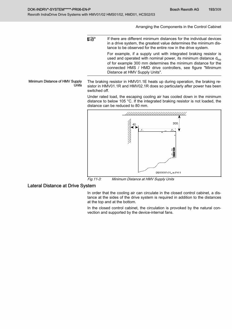
If there are different minimum distances for the individual devicesin a drive system, the greatest value determines the minimum dis‐tance to be observed for the entire row in the drive system.For example, if a supply unit with integrated braking resistor isused and operated with nominal power, its minimum distance dtopof for example 300 mm determines the minimum distance for theconnected HMS / HMD drive controllers, see figure "MinimumDistance at HMV Supply Units".
Minimum Distance of HMV SupplyUnits
The braking resistor in HMV01.1E heats up during operation, the braking re‐sistor in HMV01.1R and HMV02.1R does so particularly after power has beenswitched off.Under rated load, the escaping cooling air has cooled down in the minimumdistance to below 105 °C. If the integrated braking resistor is not loaded, thedistance can be reduced to 80 mm.
Fig.11-3: Minimum Distance at HMV Supply Units
Lateral Distance at Drive SystemIn order that the cooling air can circulate in the closed control cabinet, a dis‐tance at the sides of the drive system is required in addition to the distancesat the top and at the bottom.In the closed control cabinet, the circulation is provoked by the natural con‐vection and supported by the device-internal fans.
DOK-INDRV*-SYSTEM*****-PR06-EN-P Rexroth IndraDrive Drive Systems with HMV01/02 HMS01/02, HMD01, HCS02/03
Bosch Rexroth AG 193/309
Arranging the Components in the Control Cabinet

11.1.3 Boring Dimensions for the Mounting PlateIndividually Arranged Devices
Fig.11-4: Boring dimensions
The figure shows the back of a device.
Device K[mm]
L[mm]
M[mm]
P[mm]
R[mm]
Notes
HCS02.1E-W0012 0 316 32,5 13 7 Observe additional distance to lateralneighboring devices
HCS02.1E-W0028 0 378 32,5 13 7 Observe additional distance to lateralneighboring devices
HCS02.1E-W0054 55 378 25 13 7 Observe additional distance to lateralneighboring devices
HCS02.1E-W0070 55 378 25 13 7 Observe additional distance to lateralneighboring devices
HCS03.1E-W0070 75 466 25 13 7
HCS03.1E-W0100 175 466 25 13 7
HCS03.1E-W0150 175 466 25 13 7
Bosch Rexroth AG DOK-INDRV*-SYSTEM*****-PR06-EN-P Rexroth IndraDrive Drive Systems with HMV01/02 HMS01/02, HMD01, HCS02/03
194/309
Arranging the Components in the Control Cabinet

Device K[mm]
L[mm]
M[mm]
P[mm]
R[mm]
Notes
HCS03.1E-W0210 250 466 50 13 7
HMV01.1E-W0030 100 466 25 13 7
HMV01.1E-W0075 200 466 25 13 7
HMV01.1E-W0120 300 466 25 13 7
HMV01.1R-W0018 125 466 25 13 7
HMV01.1R-W0045 200 466 25 13 7
HMV01.1R-W0065 300 466 25 13 7
HMV01.1R-W0120 300 466 25 13 7
HMV02.1R-W0015 100 378 25 13 7
HMS01.1N-W0020 0 466 25 13 7
HMS01.1N-W0036 0 466 25 13 7
HMS01.1N-W0054 0 466 25 13 7
HMS01.1N-W0070 50 466 25 13 7
HMS01.1N-W0150 100 466 25 13 7
HMS01.1N-W0210 150 466 25 13 7
HMS01.1N-W0350 300 466 25 13 7
HMS02.1N-W0028 0 378 25 13 7
HMS02.1N-W0054 0 378 25 13 7
HMD01.1N-W0012 0 466 25 13 7
HMD01.1N-W0020 0 466 25 13 7
HMD01.1N-W0036 0 466 25 13 7
HNL02.1 100 378 20 13 7
HNS02.1 0 378 55 13 7
HLB01.1C 0 378 32,5 13 7
HLB01.1D 50 466 25 13 7
HLC01.1C-01M0 0 378 25 13 7
HLC01.1C-02M4 0 378 25 13 7
HLC01.1D-05M0 0 466 25 13 7
Tab.11-2: Boring dimensions
Ground the housings of the devices!1. Connect the bare metal back panel of the device in conductive form to
the mounting surface in the control cabinet.2. Use the supplied mounting screws and fix the screws with a tightening
torque of typically 6 Nm.3. Connect the mounting surface of the control cabinet in conductive form
to the equipment grounding system.
DOK-INDRV*-SYSTEM*****-PR06-EN-P Rexroth IndraDrive Drive Systems with HMV01/02 HMS01/02, HMD01, HCS02/03
Bosch Rexroth AG 195/309
Arranging the Components in the Control Cabinet
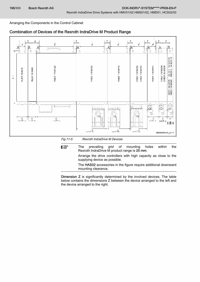
Combination of Devices of the Rexroth IndraDrive M Product Range
Fig.11-5: Rexroth IndraDrive M Devices
The prevailing grid of mounting holes within theRexroth IndraDrive M product range is 25 mm.Arrange the drive controllers with high capacity as close to thesupplying device as possible.The HAS02 accessories in the figure require additional downwardmounting clearance.
Dimension Z is significantly determined by the involved devices. The tablebelow contains the dimensions Z between the device arranged to the left andthe device arranged to the right.
Bosch Rexroth AG DOK-INDRV*-SYSTEM*****-PR06-EN-P Rexroth IndraDrive Drive Systems with HMV01/02 HMS01/02, HMD01, HCS02/03
196/309
Arranging the Components in the Control Cabinet

Device to the left Device to the right Dimension Z[mm]
HMV01.1E-W0030HMV01.1E-W0075HMV01.1E-W0120HMV01.1R-W0018HMV01.1R-W0045HMV01.1R-W0065HMV01.1R-W0120HMS01.1N-W0020HMS01.1N-W0036HMS01.1N-W0070HMS01.1N-W0110HMS01.1N-W0150HMS01.1N-W0210HMS01.1N-W0350HMD01.1N-W0012HMD01.1N-W0020
HMS01.1N-W0020HMS01.1N-W0036HMS01.1N-W0054HMS01.1N-W0070HMS01.1N-W0110HMS01.1N-W0150HMS01.1N-W0210HMS01.1N-W0350HMD01.1N-W0012HMD01.1N-W0020HMD01.1N-W0036HLC01.1D-05M0
HLB01.1D
50
HMV01.1E-W0030HMV01.1E-W0075HMV01.1E-W0120HMV01.1R-W0018HMV01.1R-W0045HMV01.1R-W0065HMV01.1R-W0120HMS01.1N-W0020HMS01.1N-W0036HMS01.1N-W0070HMS01.1N-W0110HMS01.1N-W0150HMS01.1N-W0210HMS01.1N-W0350HMD01.1N-W0012HMD01.1N-W0020
HLB01.1C 57,5
DOK-INDRV*-SYSTEM*****-PR06-EN-P Rexroth IndraDrive Drive Systems with HMV01/02 HMS01/02, HMD01, HCS02/03
Bosch Rexroth AG 197/309
Arranging the Components in the Control Cabinet
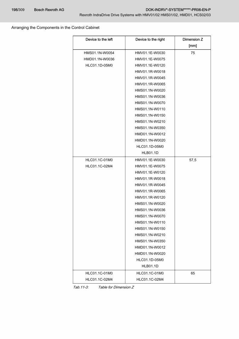
Device to the left Device to the right Dimension Z[mm]
HMS01.1N-W0054HMD01.1N-W0036HLC01.1D-05M0
HMV01.1E-W0030HMV01.1E-W0075HMV01.1E-W0120HMV01.1R-W0018HMV01.1R-W0045HMV01.1R-W0065HMS01.1N-W0020HMS01.1N-W0036HMS01.1N-W0070HMS01.1N-W0110HMS01.1N-W0150HMS01.1N-W0210HMS01.1N-W0350HMD01.1N-W0012HMD01.1N-W0020HLC01.1D-05M0
HLB01.1D
75
HLC01.1C-01M0HLC01.1C-02M4
HMV01.1E-W0030HMV01.1E-W0075HMV01.1E-W0120HMV01.1R-W0018HMV01.1R-W0045HMV01.1R-W0065HMV01.1R-W0120HMS01.1N-W0020HMS01.1N-W0036HMS01.1N-W0070HMS01.1N-W0110HMS01.1N-W0150HMS01.1N-W0210HMS01.1N-W0350HMD01.1N-W0012HMD01.1N-W0020HLC01.1D-05M0
HLB01.1D
57,5
HLC01.1C-01M0HLC01.1C-02M4
HLC01.1C-01M0HLC01.1C-02M4
65
Tab.11-3: Table for Dimension Z
Bosch Rexroth AG DOK-INDRV*-SYSTEM*****-PR06-EN-P Rexroth IndraDrive Drive Systems with HMV01/02 HMS01/02, HMD01, HCS02/03
198/309
Arranging the Components in the Control Cabinet

Combination of Drive Controllers of the Rexroth IndraDrive C Product Range
Fig.11-6: Rexroth IndraDrive C Devices
The accessory HAS04 requires additional mounting clearance atthe HCS arranged at the utmost left position.Rexroth IndraDrive devices are arranged in line to the right start‐ing from the supplying device. Arrange the drive controllers withhigh capacity as close to the supplying device as possible.The HAS02 accessories in the figure require additional downwardmounting clearance.
Dimension Z is significantly determined by the involved devices. The tablebelow contains the dimensions Z between the device arranged to the left andthe device arranged to the right.
DOK-INDRV*-SYSTEM*****-PR06-EN-P Rexroth IndraDrive Drive Systems with HMV01/02 HMS01/02, HMD01, HCS02/03
Bosch Rexroth AG 199/309
Arranging the Components in the Control Cabinet

Device to the left Device to the right Dimension Z[mm]
HCS02.1E-W0012HCS02.1E-W0028
HLB01.1C
HCS02.1E-W0012HCS02.1E-W0028
HLB01.1C
70
HCS02.1E-W0054HCS02.1E-W0070
HCS02.1E-W0054HCS02.1E-W0070
55
HLC01.1C-01M0HLC01.1C-02M4
HCS02.1E-W0054HCS02.1E-W0070
HLC01.1C-01M0HLC01.1C-02M4
50(without a distancebetween the devi‐
ces)
HCS02.1E-W0012HCS02.1E-W0028
HLB01.1C
HLC01.1C-01M0HLC01.1C-02M4
57,5(without a distancebetween the devi‐
ces)
HCS02.1E-W0054HCS02.1E-W0070HLC01.1C-01M0HLC01.1C-02M4
HCS02.1E-W0012HCS02.1E-W0028
HLB01.1C
62,5
HCS03.1E-W0070HCS03.1E-W0100HCS03.1E-W0150
HCS03.1E-W0070HCS03.1E-W0100HCS03.1E-W0150
50(without a distancebetween the devi‐
ces)
HCS03.1E-W0210 HCS03.1E-W0210 100(without a distancebetween the devi‐
ces)
HCS03.1E-W0070HCS03.1E-W0100HCS03.1E-W0150
HCS03.1E-W0210 75(without a distancebetween the devi‐
ces)
HCS03.1E-W0210 HCS03.1E-W0070HCS03.1E-W0100HCS03.1E-W0150
75(without a distancebetween the devi‐
ces)
Tab.11-4: Table for Dimension Z
Combination of Drive Controllers of the Rexroth IndraDrive C and M Product Ranges
The accessory HAS04 requires additional mounting clearance atthe HCS arranged at the utmost left position.Rexroth IndraDrive M devices are arranged in line to the rightstarting from the supplying drive controller HCS.
Bosch Rexroth AG DOK-INDRV*-SYSTEM*****-PR06-EN-P Rexroth IndraDrive Drive Systems with HMV01/02 HMS01/02, HMD01, HCS02/03
200/309
Arranging the Components in the Control Cabinet

Dimension Z is significantly determined by the involved devices. The tablebelow contains the dimensions Z between the device arranged to the left andthe device arranged to the right.
HCS02 Drive Controllers Device to the left Device to the right Dimension Z[mm]
HCS02.1E-W0054HCS02.1E-W0070
HMS01.1N-W0020HMS01.1N-W0036HMS01.1N-W0054HMS02.1N-W0028HMS02.1N-W0054HMD01.1N-W0012HMD01.1N-W0020HMD01.1N-W0036HLC01.1D-05M0
HLB01.1D
50(without a distancebetween the devi‐
ces)
Tab.11-5: Table for Dimension ZHCS03 Drive Controllers Device to the left Device to the right Dimension Z
[mm]
HCS03.1E-W0070HCS03.1E-W0100HCS03.1E-W0150
HMS01.1N-W0020HMS01.1N-W0036HMS01.1N-W0054HMS01.1N-W0070HMD01.1N-W0012HMD01.1N-W0020HMD01.1N-W0036
50(without a distancebetween the devi‐
ces)
HCS03.1E-W0210 HMS01.1N-W0020HMS01.1N-W0036HMS01.1N-W0054HMS01.1N-W0070HMS01.1N-W0110HMS01.1N-W0150HMD01.1N-W0012HMD01.1N-W0020HMD01.1N-W0036
75(without a distancebetween the devi‐
ces)
Tab.11-6: Table for Dimension Z
For the dimensions Z between other combinations see previoustables.
11.2 Arranging Components From Electrical Point of View11.2.1 General Information
The section below contains information and recommendations on the ar‐rangement of the devices in the control cabinet from mainly electrical points
DOK-INDRV*-SYSTEM*****-PR06-EN-P Rexroth IndraDrive Drive Systems with HMV01/02 HMS01/02, HMD01, HCS02/03
Bosch Rexroth AG 201/309
Arranging the Components in the Control Cabinet
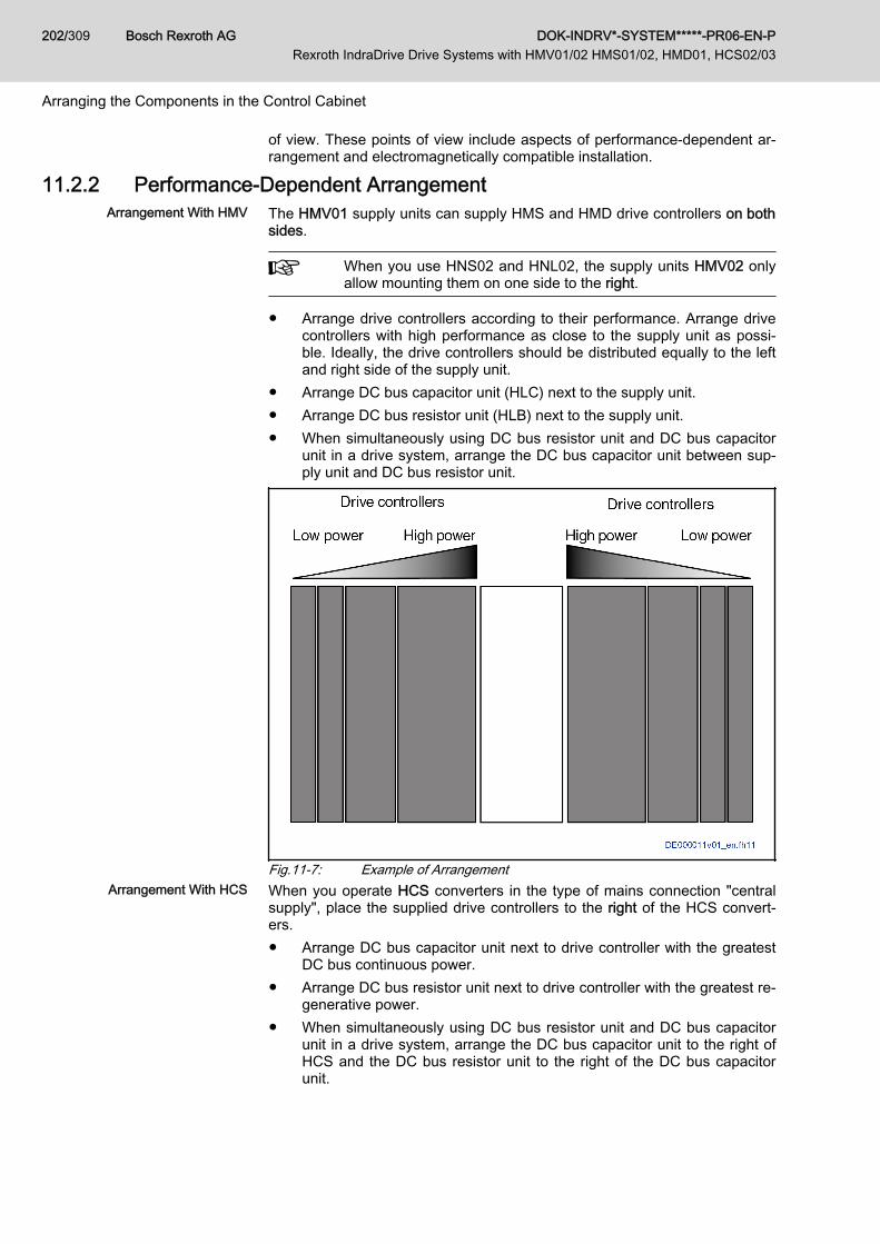
of view. These points of view include aspects of performance-dependent ar‐rangement and electromagnetically compatible installation.
11.2.2 Performance-Dependent Arrangement Arrangement With HMV The HMV01 supply units can supply HMS and HMD drive controllers on both
sides.
When you use HNS02 and HNL02, the supply units HMV02 onlyallow mounting them on one side to the right.
● Arrange drive controllers according to their performance. Arrange drivecontrollers with high performance as close to the supply unit as possi‐ble. Ideally, the drive controllers should be distributed equally to the leftand right side of the supply unit.
● Arrange DC bus capacitor unit (HLC) next to the supply unit.● Arrange DC bus resistor unit (HLB) next to the supply unit.● When simultaneously using DC bus resistor unit and DC bus capacitor
unit in a drive system, arrange the DC bus capacitor unit between sup‐ply unit and DC bus resistor unit.
Fig.11-7: Example of ArrangementArrangement With HCS When you operate HCS converters in the type of mains connection "central
supply", place the supplied drive controllers to the right of the HCS convert‐ers.● Arrange DC bus capacitor unit next to drive controller with the greatest
DC bus continuous power.● Arrange DC bus resistor unit next to drive controller with the greatest re‐
generative power.● When simultaneously using DC bus resistor unit and DC bus capacitor
unit in a drive system, arrange the DC bus capacitor unit to the right ofHCS and the DC bus resistor unit to the right of the DC bus capacitorunit.
Bosch Rexroth AG DOK-INDRV*-SYSTEM*****-PR06-EN-P Rexroth IndraDrive Drive Systems with HMV01/02 HMS01/02, HMD01, HCS02/03
202/309
Arranging the Components in the Control Cabinet

● Arrange HLR braking resistors in "standard" design above the HCS03drive controller.
11.2.3 EMC Measures for Design and InstallationRules for Design of Installations With Drive Controllers in Compliance With EMC
The following rules are the basics for designing and installing drives in com‐pliance with EMC.
Mains filter Correctly use a mains filter recommended by Rexroth for radio interferencesuppression in the supply feeder of the drive system.
Control Cabinet Grounding Connect all metal parts of the cabinet with one another over the largest possi‐ble surface area to establish a good electrical connection. This, too, appliesto the mounting of the mains filter. If required, use serrated washers whichcut through the paint surface. Connect the cabinet door to the control cabinetusing the shortest possible grounding straps.
Line Routing Avoid coupling routes between lines with high potential of noise and noise-free lines; therefore, signal, mains and motor lines and power cables have tobe routed separately from another. Minimum distance: 10 cm. Provide sepa‐rating sheets between power and signal lines. Ground separating sheets sev‐eral times.The lines with high potential of noise include:● Lines at the mains connection (incl. synchronization connection)● Lines at the motor connection● Lines at the DC bus connectionGenerally, interference injections are reduced by routing cables close togrounded sheet steel plates. For this reason, cables and wires should not berouted freely in the cabinet, but close to the cabinet housing or mounting pan‐els. Separate the incoming and outgoing cables of the radio interference sup‐pression filter.
Interference Suppression Ele‐ments
Provide the following components in the control cabinet with interference sup‐pression combinations:● Contactors● Relays● Solenoid valves● Electromechanical operating hours countersConnect these combinations directly at each coil.
Twisted Wires Twist unshielded wires belonging to the same circuit (feeder and return ca‐ble) or keep the surface between feeder and return cable as small as possi‐ble. Wires that are not used have to be grounded at both ends.
Lines of Measuring Systems Lines of measuring systems must be shielded. Connect the shield to groundat both ends and over the largest possible surface area. The shield may notbe interrupted, e.g. using intermediate terminals.
Digital Signal Lines Ground the shields of digital signal lines at both ends (transmitter and receiv‐er) over the largest possible surface area and with low impedance. In thecase of bad ground connection between transmitter and receiver, additionallyroute a bonding conductor (min. 10 mm2). Braided shields are better than foilshields.
Analog Signal Lines Ground the shields of analog signal lines at one end (transmitter or receiver)over the largest possible surface area and with low impedance. This avoidslow-frequency interference current (in the mains frequency range) on theshield.
DOK-INDRV*-SYSTEM*****-PR06-EN-P Rexroth IndraDrive Drive Systems with HMV01/02 HMS01/02, HMD01, HCS02/03
Bosch Rexroth AG 203/309
Arranging the Components in the Control Cabinet

Connecting the Mains Choke Keep connection lines of the mains choke at the drive controller as short aspossible and twist them.
Installing the Motor Power Cable ● Use shielded motor power cables or run motor power cables in a shiel‐ded duct
● Use the shortest possible motor power cables● Ground shield of motor power cable at both ends over the largest possi‐
ble surface area to establish a good electrical connection● Run motor lines in shielded form inside the control cabinet● Do not use any steel-shielded lines● The shield of the motor power cable mustn't be interrupted by mounted
components, such as output chokes, sine filters or motor filters
EMC-Optimal Installation in Facility and Control CabinetGeneral InformationFor EMC-optimal installation, a spatial separation of the interference-freearea (mains connection) and the interference-susceptible area (drive compo‐nents) is recommended, as shown in the figures below.
Recommendation: For EMC-optimal installation in the control cab‐inet, use a separate control cabinet panel for the drive compo‐nents.
Division Into Areas (Zones)Exemplary arrangements in the control cabinet: See section Control CabinetDesign According to Interference Areas - Exemplary Arrangements,page 205.We distinguish three areas:
1. Interference-free area of control cabinet (area A):This includes:● Supply feeder, input terminals, fuse, main switch, mains side of
mains filter for drives and corresponding connecting lines● Control voltage or auxiliary voltage connection with power supply
unit, fuse and other parts unless connection is run via the mains fil‐ter of the AC drives
● All components that are not electrically connected with the drivesystem
2. Interference-susceptible area (area B):● Mains connections between drive system and mains filter for
drives, mains contactor● Interface lines of drive controller
3. Strongly interference-susceptible area (area C):● Motor power cables including single cores
Never run lines of one of these areas in parallel with lines of another area sothat there isn't any unwanted interference injection from one area to the otherand that the filter is jumpered with regard to high frequency. Use the shortestpossible connecting lines.Recommendation for complex systems: Install drive components in one cabi‐net and the control units in a second, separate cabinet.
Bosch Rexroth AG DOK-INDRV*-SYSTEM*****-PR06-EN-P Rexroth IndraDrive Drive Systems with HMV01/02 HMS01/02, HMD01, HCS02/03
204/309
Arranging the Components in the Control Cabinet

Badly grounded control cabinet doors act as antennas. Therefore, connectthe control cabinet doors to the cabinet on top, in the middle and on the bot‐tom via short equipment grounding conductors with a cross section of at least6 mm2 or, even better, via grounding straps with the same cross section.Make sure connection points have good contact.
Control Cabinet Design According to Interference Areas - ExemplaryArrangements
Do not operate any additional loads at the mains filter!Do not operate any other loads at the connection from the mainsfilter output to the mains connection of the supply unit.For motor fans and power supply units, for example, use separatemains filters.
DOK-INDRV*-SYSTEM*****-PR06-EN-P Rexroth IndraDrive Drive Systems with HMV01/02 HMS01/02, HMD01, HCS02/03
Bosch Rexroth AG 205/309
Arranging the Components in the Control Cabinet

DR1 Mains chokeE1…E5 Equipment grounding conductor of the componentsK1 External mains contactor for supply units without integrated mains
contactor
Bosch Rexroth AG DOK-INDRV*-SYSTEM*****-PR06-EN-P Rexroth IndraDrive Drive Systems with HMV01/02 HMS01/02, HMD01, HCS02/03
206/309
Arranging the Components in the Control Cabinet
ML Motor fanNT Power supply unitQ1, Q2, Q3 FusingT TransformerZ1, Z2 Shield connection points for cablesFig.11-8: EMC Areas in the Control Cabinet
Design and Installation in Area A - Interference-Free Area of ControlCabinet
Arranging the Components in theControl Cabinet
Comply with recommended distance of at least 200 mm (distance d1 in thefigure):● Between components and electrical elements (switches, pushbuttons,
fuses, terminal connectors) in the interference-free area A and the com‐ponents in the two other areas B and C
Comply with recommended distance of at least 400 mm (distance d4 in thefigure):● Between magnetic components (such as transformers, mains chokes
and DC bus chokes that are directly connected to the power connec‐tions of the drive system) and the interference-free components andlines between mains and filter including the mains filter in area A
If these distances are not kept, the magnetic leakage fields are injected to theinterference-free components and lines connected to the mains and the limitvalues at the mains connection are exceeded in spite of the installed filter.
Cable Routing of the Interference-Free Lines to the Mains Connec‐
tion
Comply with recommended distance of at least 200 mm (distance d1 and d3in the figure):● Between supply feeder or lines between filter and exit point from the
control cabinet in area A and the lines in area B and CIf this is impossible, there are two alternatives:1. Install lines in shielded form and connect the shield at several points (at
least at the beginning and at the end of the line) to the mounting plate orthe control cabinet housing over a large surface area.
2. Separate lines from the other interference-susceptible lines in areas Band C by means of a grounded distance plate vertically attached to themounting plate.
Install the shortest possible lines within the control cabinet and install themdirectly on the grounded metal surface of the mounting plate or of the controlcabinet housing.Mains supply lines from areas B and C must not be connected to the mainswithout a filter.
In case you do not observe the information on cable routing givenin this section, the effect of the mains filter is totally or partly neu‐tralized. This will cause the noise level of the interference emis‐sion to be higher within the range of 150 kHz to 40 MHz and thelimit values at the connection points of the machine or installationwill thereby be exceeded. Consider the specified distances to berecommended data, provided that the dimensions of the controlcabinet allow installing the lines accordingly.
Routing and Connecting a NeutralConductor (N)
If a neutral conductor is used together with a three-phase connection, it mustnot be installed unfiltered in zones B and C, in order to keep interference offthe mains.
DOK-INDRV*-SYSTEM*****-PR06-EN-P Rexroth IndraDrive Drive Systems with HMV01/02 HMS01/02, HMD01, HCS02/03
Bosch Rexroth AG 207/309
Arranging the Components in the Control Cabinet
Motor Fan at Mains Filter Single-phase or three-phase supply lines of motor fans, that are usually rout‐ed in parallel with motor power cables or interference-susceptible lines, mustbe filtered:● In drive systems with regenerative supply units, via a separate single-
phase (NFE type) or three-phase filter (HNF type) near the mains con‐nection of the control cabinet
● In drive systems with only infeeding supply units, via the available three-phase filter of the drive system
When switching power off, make sure the fan is not switched off.When switching power off, make sure the fan is not switched off.
Loads at Mains Filter of Drive Sys‐tem Only operate allowed loads at the mains filter of the drive system!
At the three-phase filter for the power connection of regenerativesupply units, it is only allowed to operate the following loads:● HMV supply unit with mains choke and, if necessary, mains
contactorDo not operate any motor fans, power supply units etc. at themains filter of the drive system.
Shielding Mains Supply Lines inControl Cabinet
If there is a high degree of interference injection to the mains supply line with‐in the control cabinet, although you have observed the above instructions (tobe found out by EMC measurement according to standard), proceed as fol‐lows:● Only use shielded lines in area A● Connect shields to the mounting plate at the beginning and the end of
the line by means of clipsThe same procedure may be required for long cables of more than 2 m be‐tween the point of power supply connection of the control cabinet and the fil‐ter within the control cabinet.
Mains Filters for AC Drives Ideally mount the mains filter on the parting line between the areas A and B.Make sure the ground connection between filter housing and housing of thedrive controllers has good electrically conductive properties.If single-phase loads are connected on the load side of the filter, their currentmay be a maximum of 10% of the three-phase operating current. A highly im‐balanced load of the filter would deteriorate its interference suppression ca‐pacity.If the mains voltage is more than 480 V, connect the filter to the output side ofthe transformer and not to the supply side of the transformer.
Grounding In the case of bad ground connections in the installation, the distance be‐tween the lines to the grounding points E1, E2 in area A and the othergrounding points of the drive system should be at least d4 = 400 mm, in orderto minimize interference injection from ground and ground cables to the pow‐er input lines.See also Division Into Areas (Zones), page 204.
Point of Connection for EquipmentGrounding Conductor at Machine,
Installation, Control Cabinet
The equipment grounding conductor of the power cable of the machine, in‐stallation or control cabinet has to be permanently connected at point PE andhave a cross section of at least 10 mm2 or to be complemented by a secondequipment grounding conductor via separate terminal connectors (accordingto EN 61800-5-1:2007, section 4.3.5.5.2). If the cross section of the outerconductor is bigger, the cross section of the equipment grounding conductormust be accordingly bigger.
Bosch Rexroth AG DOK-INDRV*-SYSTEM*****-PR06-EN-P Rexroth IndraDrive Drive Systems with HMV01/02 HMS01/02, HMD01, HCS02/03
208/309
Arranging the Components in the Control Cabinet
Design and Installation in Area B - Interference-Susceptible Area ofControl Cabinet
Arranging Components and Lines Modules, components and lines in area B should be placed at a distance ofat least d1 = 200 mm from modules and lines in area A.Alternative: Shield modules, components and lines in area B by distanceplates mounted vertically on the mounting plate from modules and lines inarea A or use shielded lines.Only connect power supply units for auxiliary or control voltage connectionsin the drive system to the mains via a mains filter. See Division Into Areas(Zones), page 204.Install the shortest possible lines between drive controller and filter.
Control Voltage or Auxiliary Volt‐age Connection
Only in exceptional cases should you connect power supply unit and fusingfor the control voltage connection to phase and neutral conductor. In thiscase, mount and install these components in area A far away from the areasB and C of the drive system. For details see section Design and Installation inArea A - Interference-Free Area of Control Cabinet, page 207.Run the connection between control voltage connection of the drive systemand power supply unit used through area B over the shortest distance.
Line Routing Run the lines along grounded metal surfaces, in order to minimize radiationof interference fields to area A (transmitting antenna effect).
Design and Installation in Area C - Strongly Interference-SusceptibleArea of Control CabinetArea C mainly concerns the motor power cables, especially at the connectionpoint at the drive controller.
Influence of the Motor Power Ca‐ble
The longer the motor power cable, the greater its leakage capacitance. Tocomply with a certain EMC limit value, the allowed leakage capacitance ofthe mains filter is limited. For the calculation of the leakage capacitance, seethe documentation on the drive system of the drive controller used.
● Run the shortest possible motor power cables.● Only use shielded motor power cables by Rexroth.
Routing the Motor Power Cablesand Motor Encoder Cables
Route the motor power cables and motor encoder cables along groundedmetal surfaces, both inside the control cabinet and outside of it, in order tominimize radiation of interference fields. If possible, route the motor powercables and motor encoder cables in metal-grounded cable ducts.Route the motor power cables and motor encoder cables● with a distance of at least d5 = 100 mm to interference-free lines, as
well as to signal cables and signal lines(alternatively separated by a grounded distance plate)
● in separate cable ducts, if possibleRouting the Motor Power Cables
and Mains Connection LinesFor converters (drive controllers with individual mains connection), route mo‐tor power cables and (unfiltered) mains connection lines in parallel for a maxi‐mum distance of 300 mm. After that distance, route motor power cables andpower supply cables in opposite directions and preferably in separate cableducts.Ideally, the outlet of the motor power cables at the control cabinet should beprovided in a distance of at least d3 = 200 mm from the (filtered) power sup‐ply cable.
DOK-INDRV*-SYSTEM*****-PR06-EN-P Rexroth IndraDrive Drive Systems with HMV01/02 HMS01/02, HMD01, HCS02/03
Bosch Rexroth AG 209/309
Arranging the Components in the Control Cabinet
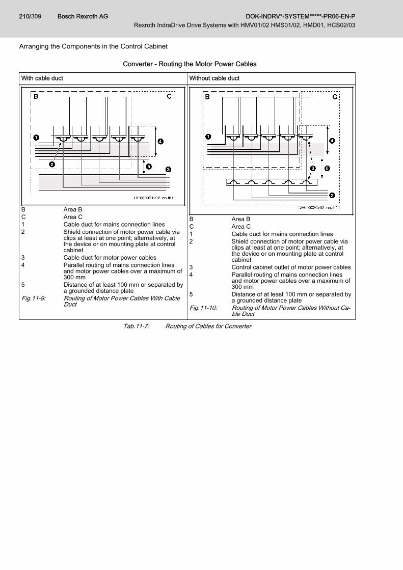
Converter - Routing the Motor Power Cables
With cable duct Without cable duct
B Area BC Area C1 Cable duct for mains connection lines2 Shield connection of motor power cable via
clips at least at one point; alternatively, atthe device or on mounting plate at controlcabinet
3 Cable duct for motor power cables4 Parallel routing of mains connection lines
and motor power cables over a maximum of300 mm
5 Distance of at least 100 mm or separated bya grounded distance plate
Fig.11-9: Routing of Motor Power Cables With CableDuct
B Area BC Area C1 Cable duct for mains connection lines2 Shield connection of motor power cable via
clips at least at one point; alternatively, atthe device or on mounting plate at controlcabinet
3 Control cabinet outlet of motor power cables4 Parallel routing of mains connection lines
and motor power cables over a maximum of300 mm
5 Distance of at least 100 mm or separated bya grounded distance plate
Fig.11-10: Routing of Motor Power Cables Without Ca‐ble Duct
Tab.11-7: Routing of Cables for Converter
Bosch Rexroth AG DOK-INDRV*-SYSTEM*****-PR06-EN-P Rexroth IndraDrive Drive Systems with HMV01/02 HMS01/02, HMD01, HCS02/03
210/309
Arranging the Components in the Control Cabinet

Inverter - Routing the Motor Power Cables
With cable duct Without cable duct
B Area BC Area C1 Cable duct for mains connection lines2 Shield connection of motor power cable via
clips at least at one point; alternatively, atthe device or on mounting plate at controlcabinet
3 Cable duct for motor power cablesFig.11-11: Routing of Motor Power Cables With Cable
Duct
B Area BC Area C1 Cable duct for mains connection lines2 Shield connection of motor power cable via
clips at least at one point; alternatively, atthe device or on mounting plate at controlcabinet
3 Control cabinet outlet of motor power cablesFig.11-12: Routing of Motor Power Cables Without Ca‐
ble Duct
Tab.11-8: Routing of Cables for Inverter
Ground ConnectionsHousing and Mounting Plate By means of appropriate ground connections, it is possible to avoid the emis‐
sion of interference, because interference is discharged to ground on theshortest possible way.Ground connections of the metal housings of EMC-critical components (suchas filters, devices of the drive system, connection points of the cable shields,devices with microprocessor and switching power supply units) have to bewell contacted over a large surface area. This also applies to all screw con‐nections between mounting plate and control cabinet wall and to the mount‐ing of a ground bus to the mounting plate.The best solution is to use a zinc-coated mounting plate. Compared to a var‐nished plate, the connections in this case have a good long-time stability.
Connection Elements For varnished mounting plates, always use screw connections with tooth lockwashers and zinc-coated, tinned screws as connection elements. At the con‐nection points, remove the varnish so that there is safe electrical contact overa large surface area. You achieve contact over a large surface area bymeans of bare connection surfaces or several connection screws. For screwconnections, you can establish the contact to varnished surfaces by usingtooth lock washers.
Metal Surfaces Always use connection elements (screws, nuts, plain washers) with goodelectroconductive surface.Bare zinc-coated or tinned metal surfaces have good electroconductive prop‐erties.
DOK-INDRV*-SYSTEM*****-PR06-EN-P Rexroth IndraDrive Drive Systems with HMV01/02 HMS01/02, HMD01, HCS02/03
Bosch Rexroth AG 211/309
Arranging the Components in the Control Cabinet
Anodized, yellow chromatized, black gunmetal finish or lacquered metal sur‐faces have bad electroconductive properties.
Ground Wires and Shield Connec‐tions
For connecting ground wires and shield connections, it is not the cross sec‐tion but the size of contact surface that is important, as the high-frequency in‐terference currents mainly flow on the surface of the conductor.Always connect cable shields, especially shields of the motor power cables,to ground potential over a large surface area.
Installing Signal Lines and Signal CablesLine Routing For measures to prevent interference, see the Project Planning Manuals of
the respective device. In addition, we recommend the following measures:● Route signal and control lines separately from the power cables with a
minimum distance of d5 = 100 mm (see Division Into Areas (Zones),page 204) or with a grounded separating sheet. The optimum way is toroute them in separate cable ducts. If possible, lead signal lines into thecontrol cabinet at one point only.
● If signal lines are crossing power cables, route them in an angle of 90°in order to avoid interference injection.
● Ground spare cables, that are not used and have been connected, atleast at both ends so that they do not have any antenna effect.
● Avoid unnecessary line lengths.● Run cables as close as possible to grounded metal surfaces (reference
potential). The ideal solution are closed, grounded cable ducts or metalpipes which, however, is only obligatory for high requirements (sensitiveinstrument leads).
● Avoid suspended lines or lines routed along synthetic carriers, becausethey are functioning like reception antennas (noise immunity) and liketransmitting antennas (emission of interference). Exceptional cases areflexible cable tracks over short distances of a maximum of 5 m.
Shielding Connect the cable shield immediately at the devices in the shortest and mostdirect possible way and over the largest possible surface area.Connect the shield of analog signal lines at one end over a large surfacearea, normally in the control cabinet at the analog device. Make sure the con‐nection to ground/housing is short and over a large surface area.Connect the shield of digital signal lines at both ends over a large surfacearea and in short form. In the case of potential differences between beginningand end of the line, run an additional bonding conductor in parallel. This pre‐vents compensating current from flowing via the shield. The guide value forthe cross section is 10 mm2.You absolutely have to equip separable connections with connectors withgrounded metal housing.In the case of non-shielded lines belonging to the same circuit, twist feederand return cable.
General Measures of Radio Interference Suppression for Relays, Contactors, Switches,Chokes and Inductive Loads
If, in conjunction with electronic devices and components, inductive loads,such as chokes, contactors, relays are switched by contacts or semiconduc‐tors, appropriate interference suppression has to be provided for them:● By arranging free-wheeling diodes in the case of d.c. operation
Bosch Rexroth AG DOK-INDRV*-SYSTEM*****-PR06-EN-P Rexroth IndraDrive Drive Systems with HMV01/02 HMS01/02, HMD01, HCS02/03
212/309
Arranging the Components in the Control Cabinet

● In the case of a.c. operation, by arranging usual RC interference sup‐pression elements depending on the contactor type, immediately at theinductance
Only the interference suppression element arranged immediately at the in‐ductance does serve this purpose. Otherwise, the emitted noise level is toohigh which can affect the function of the electronic system and of the drive.
DOK-INDRV*-SYSTEM*****-PR06-EN-P Rexroth IndraDrive Drive Systems with HMV01/02 HMS01/02, HMD01, HCS02/03
Bosch Rexroth AG 213/309
Arranging the Components in the Control Cabinet

Bosch Rexroth AG DOK-INDRV*-SYSTEM*****-PR06-EN-P Rexroth IndraDrive Drive Systems with HMV01/02 HMS01/02, HMD01, HCS02/03
214/309

12 Project Planning of Cooling System12.1 Control Cabinet12.1.1 Control Cabinet Design and Cooling
The only mounting position allowed for supply units and drivecontrollers to be installed in control cabinets is G1.
Possibilities of Heat Dissipation
Closed control cabinet withair circulation
Closed control cabinet withheat exchanger
Control cabinet with fan Closed control cabinet withair conditioning unit
PQ ~ 400 W PQ ~ 1700 W PQ ~ 2700 W PQ ~ 4000 W
PQ Dissipated heat outputTab.12-1: Possibilities of Heat DissipationThe section below describes the "control cabinet with fan".
Requirements for Control Cabinetswith Fan Risk of damage by unclean air in the control
cabinet!NOTICE
Operating a control cabinet with a fan, but without the corresponding filters,can damage the devices or cause malfunction.
● Install filters at the air intake opening of the control cabinet so that im‐pure air cannot get into the control cabinet.
● Service the filters at regular intervals according to the dust loading in theenvironment.
● Only replace the filters when the fan has been switched off, becauseotherwise the fan sucks in the dirt coming off the filter and the dirt getsinto the control cabinet.
DOK-INDRV*-SYSTEM*****-PR06-EN-P Rexroth IndraDrive Drive Systems with HMV01/02 HMS01/02, HMD01, HCS02/03
Bosch Rexroth AG 215/309
Project Planning of Cooling System
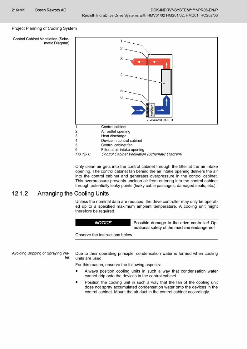
Control Cabinet Ventilation (Sche‐matic Diagram)
1 Control cabinet2 Air outlet opening3 Heat discharge4 Device in control cabinet5 Control cabinet fan6 Filter at air intake openingFig.12-1: Control Cabinet Ventilation (Schematic Diagram) Only clean air gets into the control cabinet through the filter at the air intakeopening. The control cabinet fan behind the air intake opening delivers the airinto the control cabinet and generates overpressure in the control cabinet.This overpressure prevents unclean air from entering into the control cabinetthrough potentially leaky points (leaky cable passages, damaged seals, etc.).
12.1.2 Arranging the Cooling UnitsUnless the nominal data are reduced, the drive controller may only be operat‐ed up to a specified maximum ambient temperature. A cooling unit mighttherefore be required.
Possible damage to the drive controller! Op‐erational safety of the machine endangered!
NOTICE
Observe the instructions below.
Avoiding Dripping or Spraying Wa‐
terDue to their operating principle, condensation water is formed when coolingunits are used.For this reason, observe the following aspects:● Always position cooling units in such a way that condensation water
cannot drip onto the devices in the control cabinet.● Position the cooling unit in such a way that the fan of the cooling unit
does not spray accumulated condensation water onto the devices in thecontrol cabinet. Mount the air duct in the control cabinet accordingly.
Bosch Rexroth AG DOK-INDRV*-SYSTEM*****-PR06-EN-P Rexroth IndraDrive Drive Systems with HMV01/02 HMS01/02, HMD01, HCS02/03
216/309
Project Planning of Cooling System

Cooling Unit on Top of the Control Cabinet Cooling Unit at the Front of the Control Cabinet
1 Cooling unit2 Interior of control cabinet3 Air duct (protects devices against condensation water)4 Device in control cabinetTab.12-2: Arranging the Cooling Units
Avoiding Moisture Condensation Moisture condensation occurs when the temperature of the device is lowerthan the ambient temperature.● Set cooling units with temperature adjustment to the maximum sur‐
rounding temperature and not lower!● Set cooling units with follow-up temperature in such a way that the inte‐
rior temperature of the control cabinet is not lower than the temperatureof the surrounding air. Set the temperature limitation to the maximumsurrounding temperature!
● Only use well-sealed control cabinets so that moisture condensationcannot arise as a result of warm and moist external air entering the cabi‐net.
● In the event that control cabinets are operated with the doors open(commissioning, servicing etc.), it is essential to ensure that after thedoors are closed the drive controllers cannot at any time be cooler thanthe air in the control cabinet. For this reason, sufficient circulation mustbe provided inside the control cabinet.
DOK-INDRV*-SYSTEM*****-PR06-EN-P Rexroth IndraDrive Drive Systems with HMV01/02 HMS01/02, HMD01, HCS02/03
Bosch Rexroth AG 217/309
Project Planning of Cooling System
12.1.3 Multiple-Line Design of the Control Cabinet
Arrangement of the devices, air guides/drip protections, fansPay particular attention to the maximum allowed air intake tem‐perature of devices when they are arranged in multiple lines in thecontrol cabinet.If possible, place devices with a high degree of power dissipation(e.g. supply units with braking resistors, DC bus resistor units)● in the top line and● near the outlet air aperture to the cooling unitMount air guides between the lines to● protect the devices in the upper lines against the warm outlet
air of the devices beneath and● protect the devices beneath against penetration of liquids
(e.g. dripping condensation water or leaking cooling liquid)Additional fans convey the outlet air to the cooling unit and cool‐ing air to the upper lines.At the installed control cabinet, check the air intake temperatureof all devices.
To extend the module bus connection, the accessory RKB0001 isavailable. Observe the assignment.
Bosch Rexroth AG DOK-INDRV*-SYSTEM*****-PR06-EN-P Rexroth IndraDrive Drive Systems with HMV01/02 HMS01/02, HMD01, HCS02/03
218/309
Project Planning of Cooling System
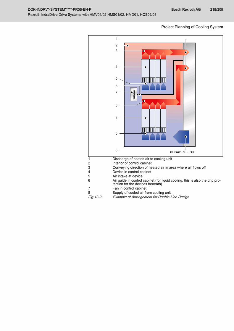
1 Discharge of heated air to cooling unit2 Interior of control cabinet3 Conveying direction of heated air in area where air flows off4 Device in control cabinet5 Air intake at device6 Air guide in control cabinet (for liquid cooling, this is also the drip pro‐
tection for the devices beneath)7 Fan in control cabinet8 Supply of cooled air from cooling unitFig.12-2: Example of Arrangement for Double-Line Design
DOK-INDRV*-SYSTEM*****-PR06-EN-P Rexroth IndraDrive Drive Systems with HMV01/02 HMS01/02, HMD01, HCS02/03
Bosch Rexroth AG 219/309
Project Planning of Cooling System

Bosch Rexroth AG DOK-INDRV*-SYSTEM*****-PR06-EN-P Rexroth IndraDrive Drive Systems with HMV01/02 HMS01/02, HMD01, HCS02/03
220/309

13 Connections of the Components in the Drive System13.1 System Connections of the Components13.1.1 General Information
Electrical connections for operating the drive system Rexroth IndraDrive:In the System Environment ● Connection X3 or PE to equipment grounding system
● Connection X3 to supply with power voltage● Connection X13 or terminal block 0V / +24V to supply with control volt‐
age● Connection to control unit and/or master communication
Within the Drive System ● Equipment grounding conductor connections PE to X3 or joint bars atthe devices
● DC bus connections L+ with bars● DC bus connections L- with bars● Control voltage connections 0V with bars● Control voltage connections +24V with bars● Module bus connections X1 with ribbon cable● Motor power connections via motor power cable at X5● Connections for motor temperature monitoring and motor holding brake
via motor power cable at X6
DOK-INDRV*-SYSTEM*****-PR06-EN-P Rexroth IndraDrive Drive Systems with HMV01/02 HMS01/02, HMD01, HCS02/03
Bosch Rexroth AG 221/309
Connections of the Components in the Drive System
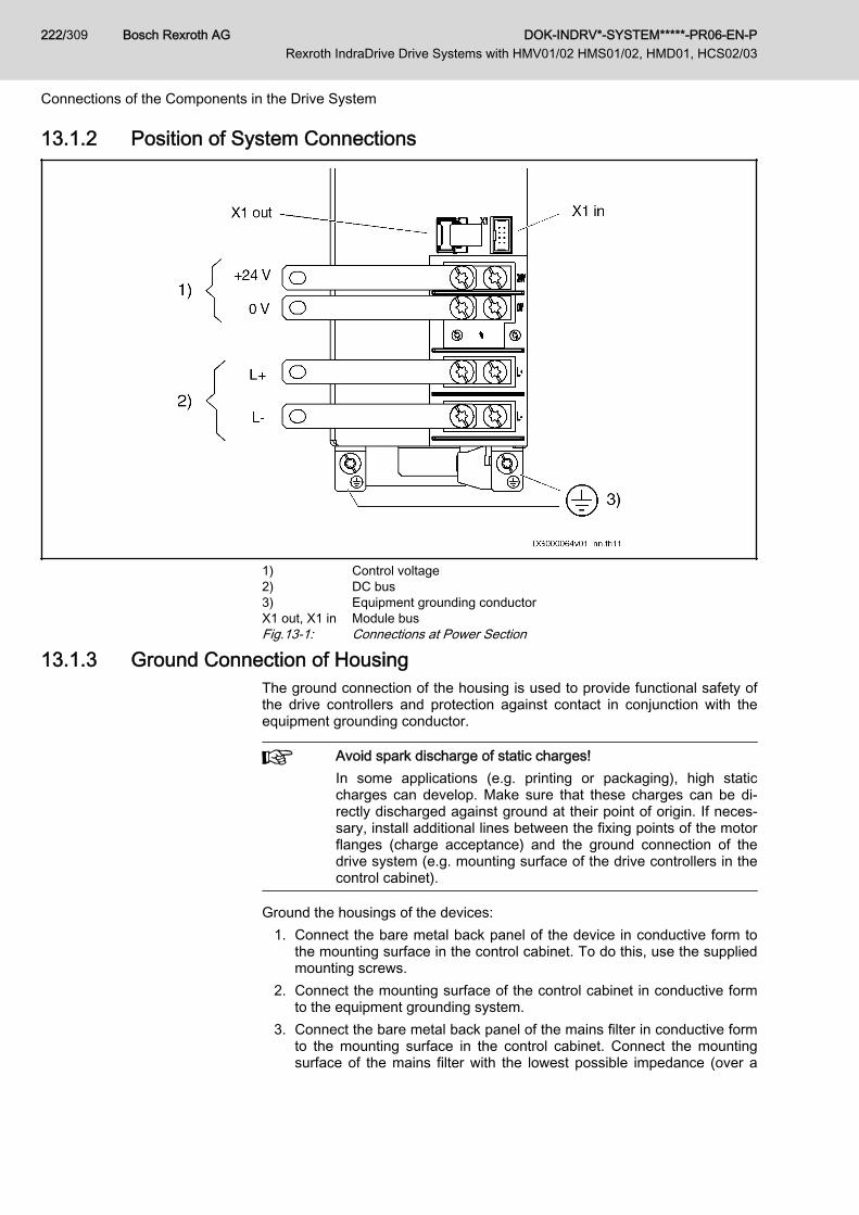
13.1.2 Position of System Connections
1) Control voltage2) DC bus3) Equipment grounding conductorX1 out, X1 in Module busFig.13-1: Connections at Power Section
13.1.3 Ground Connection of HousingThe ground connection of the housing is used to provide functional safety ofthe drive controllers and protection against contact in conjunction with theequipment grounding conductor.
Avoid spark discharge of static charges!In some applications (e.g. printing or packaging), high staticcharges can develop. Make sure that these charges can be di‐rectly discharged against ground at their point of origin. If neces‐sary, install additional lines between the fixing points of the motorflanges (charge acceptance) and the ground connection of thedrive system (e.g. mounting surface of the drive controllers in thecontrol cabinet).
Ground the housings of the devices:1. Connect the bare metal back panel of the device in conductive form to
the mounting surface in the control cabinet. To do this, use the suppliedmounting screws.
2. Connect the mounting surface of the control cabinet in conductive formto the equipment grounding system.
3. Connect the bare metal back panel of the mains filter in conductive formto the mounting surface in the control cabinet. Connect the mountingsurface of the mains filter with the lowest possible impedance (over a
Bosch Rexroth AG DOK-INDRV*-SYSTEM*****-PR06-EN-P Rexroth IndraDrive Drive Systems with HMV01/02 HMS01/02, HMD01, HCS02/03
222/309
Connections of the Components in the Drive System
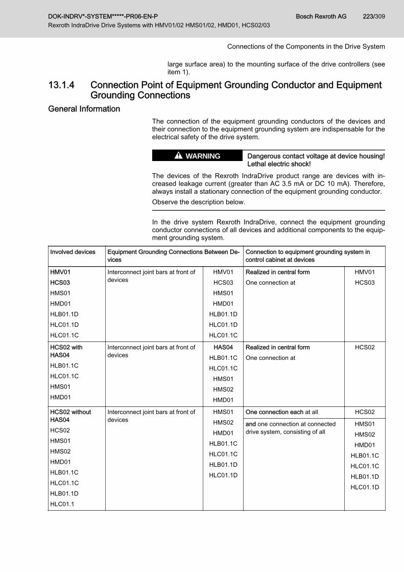
large surface area) to the mounting surface of the drive controllers (seeitem 1).
13.1.4 Connection Point of Equipment Grounding Conductor and EquipmentGrounding Connections
General InformationThe connection of the equipment grounding conductors of the devices andtheir connection to the equipment grounding system are indispensable for theelectrical safety of the drive system.
Dangerous contact voltage at device housing!Lethal electric shock!
WARNING
The devices of the Rexroth IndraDrive product range are devices with in‐creased leakage current (greater than AC 3.5 mA or DC 10 mA). Therefore,always install a stationary connection of the equipment grounding conductor.Observe the description below.
In the drive system Rexroth IndraDrive, connect the equipment groundingconductor connections of all devices and additional components to the equip‐ment grounding system.
Involved devices Equipment Grounding Connections Between De‐vices
Connection to equipment grounding system incontrol cabinet at devices
HMV01HCS03HMS01HMD01HLB01.1DHLC01.1DHLC01.1C
Interconnect joint bars at front ofdevices
HMV01HCS03HMS01HMD01
HLB01.1DHLC01.1DHLC01.1C
Realized in central formOne connection at
HMV01HCS03
HCS02 withHAS04HLB01.1CHLC01.1CHMS01HMD01
Interconnect joint bars at front ofdevices
HAS04HLB01.1CHLC01.1C
HMS01HMS02HMD01
Realized in central formOne connection at
HCS02
HCS02 withoutHAS04HCS02HMS01HMS02HMD01HLB01.1CHLC01.1CHLB01.1DHLC01.1
Interconnect joint bars at front ofdevices
HMS01HMS02HMD01
HLB01.1CHLC01.1CHLB01.1DHLC01.1D
One connection each at all HCS02
and one connection at connecteddrive system, consisting of all
HMS01HMS02HMD01
HLB01.1CHLC01.1CHLB01.1DHLC01.1D
DOK-INDRV*-SYSTEM*****-PR06-EN-P Rexroth IndraDrive Drive Systems with HMV01/02 HMS01/02, HMD01, HCS02/03
Bosch Rexroth AG 223/309
Connections of the Components in the Drive System
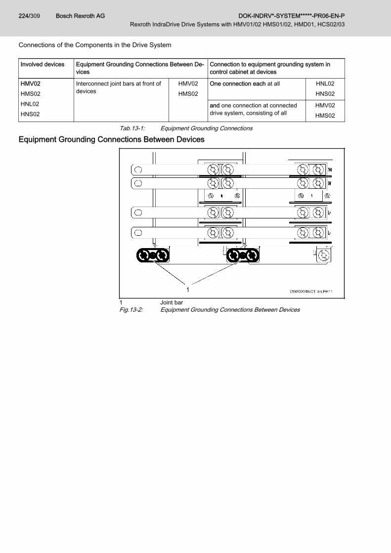
Involved devices Equipment Grounding Connections Between De‐vices
Connection to equipment grounding system incontrol cabinet at devices
HMV02HMS02HNL02HNS02
Interconnect joint bars at front ofdevices
HMV02HMS02
One connection each at all HNL02HNS02
and one connection at connecteddrive system, consisting of all
HMV02HMS02
Tab.13-1: Equipment Grounding Connections
Equipment Grounding Connections Between Devices
1 Joint barFig.13-2: Equipment Grounding Connections Between Devices
Bosch Rexroth AG DOK-INDRV*-SYSTEM*****-PR06-EN-P Rexroth IndraDrive Drive Systems with HMV01/02 HMS01/02, HMD01, HCS02/03
224/309
Connections of the Components in the Drive System

Connection to Equipment Grounding System in Control Cabinet
1 Joint bar2 Connection point for connection to equipment grounding system in
control cabinetFig.13-3: Equipment Grounding Connections
1 Joint bar2 Connection to equipment grounding systemFig.13-4: Equipment Grounding Connection in the Case of Supply via HMV01,
HMV02 or HCS03
DOK-INDRV*-SYSTEM*****-PR06-EN-P Rexroth IndraDrive Drive Systems with HMV01/02 HMS01/02, HMD01, HCS02/03
Bosch Rexroth AG 225/309
Connections of the Components in the Drive System

1 Joint bar2 Connection to equipment grounding systemFig.13-5: Equipment Grounding Conductor Connection for Supply via HCS02
Equipment grounding conductor: Material and cross sectionFor the equipment grounding conductor, use the same metal (e.g.copper) as for the outer conductors.For the connections from the equipment grounding conductorconnection of the device to the equipment grounding conductorsystem in the control cabinet, make sure the cross sections of thelines are sufficient.Cross sections of the equipment grounding connections:● For HCS03.1E drive controllers, HMV01 and HMV02 supply
units at least 10 mm2 (AWG 8), but not smaller than thecross sections of the outer conductors of the mains supplyfeeder
● For HCS02.1E drive controllers, at least 4 mm2 (AWG 10),but not smaller than the cross sections of the outer conduc‐tors of the mains supply feederAdditionally, mount the housing of HCS02.1E to a bare met‐al mounting plate. Connect the mounting plate, too, with atleast the same cross section to the equipment groundingconductor system in the control cabinet.
For outer conductors with a cross section greater than 16 mm²,you can reduce the cross section of the equipment groundingconnection according to the table "Equipment Grounding Conduc‐tor Cross Section".
Cross-sectional area A of outer conduc‐tors
Minimum cross-sectional area APE ofequipment grounding connection
A ≤ 16 mm² A
16 mm² < A ≤ 35 mm² 16
35 mm² < A A / 2
Tab.13-2: Equipment Grounding Conductor Cross Section
13.1.5 Connection to Mains Choke and Mains Filter Order of the connections to the supply mains:
Bosch Rexroth AG DOK-INDRV*-SYSTEM*****-PR06-EN-P Rexroth IndraDrive Drive Systems with HMV01/02 HMS01/02, HMD01, HCS02/03
226/309
Connections of the Components in the Drive System

Supply mains → mains filter → mains choke → supply unit or drive controller
Only operate allowed loads at the mains filter of the drive system!At the three-phase filter for the power connection of regenerativesupply units, it is only allowed to operate the following loads:● HMV supply unit with mains choke and, if necessary, mains
contactorDo not operate any motor fans, power supply units etc. at themains filter of the drive system.
The cables to the mains choke and mains filter carry a high potential of inter‐ference; you should therefore keep them as short as possible and twist them.
Allowed cable length between the components mains filter ↔mains choke and mains choke ↔ supply unit (X3, X14):At most 2 m for each cable (unshielded; twisted or run in groun‐ded, metallic channel)Shielded cables (with a cable shield connected over a large sur‐face are at both ends) may be longer than 2 m. In total, the entirecable length ([mains filter ↔ mains choke] + [mains choke ↔ sup‐ply unit]) must be less than 10 m.
1) Fusing of connection X142) Mains choke3) Mains filterFig.13-6: Synchronizing Voltage by the Example of HMV01.1ROther circuits for the mains connection: See chapter 9 "Circuits for the MainsConnection" on page 141
DOK-INDRV*-SYSTEM*****-PR06-EN-P Rexroth IndraDrive Drive Systems with HMV01/02 HMS01/02, HMD01, HCS02/03
Bosch Rexroth AG 227/309
Connections of the Components in the Drive System

13.1.6 Connection of the DC Bus ConnectionsGeneral Information
Property damage in case of error caused bytoo small line cross section!
NOTICE
Observe the current carrying capacity of the connection lines at the DC busconnections of the components used; see chapter "DC Bus Connection (L+,L-)" in the Project Planning Manual "Rexroth IndraDrive Supply Units andPower Sections".Install connection lines at the DC bus connections in such a way that they areprotected by the line protection at the mains connection of the supply unit orby additional fuses before the connection line.
Technical Data of the Connection Point
View Identifica‐tion
Function
L+ Connection points for connecting DC bus connections
L-
Screw connectionM6 thread at device (terminal block)
Unit Min. Max.
Tightening torque Nm 5,5 6,5
Short circuit protection Via fusing elements connected in the incoming circuit to themains connection
Overload protection Via fusing elements connected in the incoming circuit to themains connection
Current carrying capacity "looping through" from L+ to L+, L- to L-(contact bars in scope of supply of accessory HAS01)
With contact bars -072 A 220
Additionally with contact bars ‑042 and endpiece
A 245
Tab.13-3: Function, Pin Assignment, PropertiesSingle-Line Arrangement The figure below illustrates the connection point and connection of the DC
bus connections in the case of single-line arrangement with contact bars forthe system components● HMV01● HMS01● HMD01
Bosch Rexroth AG DOK-INDRV*-SYSTEM*****-PR06-EN-P Rexroth IndraDrive Drive Systems with HMV01/02 HMS01/02, HMD01, HCS02/03
228/309
Connections of the Components in the Drive System

● HLB01.1D● HCS03
Design
Fig.13-7: Contact barsMultiple-Line Arrangement For multiple-line arrangement of drive controllers, the connection for DC bus
and control voltage supply is realized with twisted cables.
Risk of damage to the drive controller!NOTICE● The DC bus connections of stacked drive controllers must be correctly
interconnected.● Connect L+ connections only to other L+ connections and L- connec‐
tions only to other L- connections.● Observe the measures regarding maximum allowed line lengths and
minimum required line cross sections.
Minimum Requirements to Connection LinesDielectric Strength The connection lines from the supply unit to the drive systems and between
the drive systems must have a dielectric strength of at least:● 1000 V against each other● 700 V against ground
Line Cross Section Determine the minimum line cross section from supply unit to drive systemsand between drive systems by means of the rated current. For rated current,use the higher value from the following calculations:● Calculate the mains-side phase current● Calculate the current in the branch with the greatest DC bus power
Minimum cross section ULUse in the scope of UL requires the line cross section A ≥ 35 mm2
(AWG2).
DOK-INDRV*-SYSTEM*****-PR06-EN-P Rexroth IndraDrive Drive Systems with HMV01/02 HMS01/02, HMD01, HCS02/03
Bosch Rexroth AG 229/309
Connections of the Components in the Drive System

For connecting line cross sections of 35 mm² (AWG2) and50 mm² (AWG1/0), use the accessory HAS05.1-004.
Routing Routing of the connection lines from the supply unit to drive systems and be‐tween the drive systems:● Twist the lines with the minimum possible length of lay, but 120 mm as a
maximum● With minimum mechanical distance to ground potential● With a distance of at least 200 mm to control voltage linesThe figures below illustrate the correct DC bus connection for stacked drivecontrollers. The illustrated way of connection keeps bare wire sections frombeing situated directly vis-à-vis. This avoids voltage arcing.
Maximum Allowed Line Length at DC Bus ConnectionThe line length at the DC bus connection is limited to protect the devices. Forthe maximum allowed line lengths between the electrical connections, see ta‐ble below.
Allowed line length / m
From To
HMV01 HMV02 HCS03 HCS02 HMS01 /HMD01 HMS02 HLB01 HLC01
HMV01 0,5 -- -- -- 21) -- 0,35 0,35
HMV02 -- 0,5 -- -- -- 0,35 0,35 0,35
HCS03 -- -- 0,5 -- 21) -- -- 0,35
HCS02 -- -- -- 0,5 21) 0,35 0,35 0,35
HMS01 /HMD01 -- -- -- -- 21) -- 0,35 0,35
HMS02 -- -- -- -- -- 21) 0,35 0,35
HLB01 -- -- -- -- -- 0,35 0,35
HLC01 -- -- -- -- -- -- 0,35
HLL02 - 2 - - - 2 - -
1) Additional lateral distance requires the module bus connectionRKB0001
Tab.13-4: Maximum Allowed Line Lengths at DC Bus
Line length > 2 m between supply unit and drive controllerFor arrangements of supply units which supply, for example, drivecontrollers over line lengths > 2 m, take special measures:● Use HLC01 DC bus capacitor units at every drive system.● Dimension the minimum size of HLC01 according to the pro‐
jected continuous power of the respective drive system:47 μF per kilowatt [kW] of continuous power.Example: 50 kW calculated continuous power in DC bus re‐quires 2350 μF at this system, thus at least 1HLC01.1D-02M4.
Bosch Rexroth AG DOK-INDRV*-SYSTEM*****-PR06-EN-P Rexroth IndraDrive Drive Systems with HMV01/02 HMS01/02, HMD01, HCS02/03
230/309
Connections of the Components in the Drive System

Maximum length between drive systems and drive controllersMultiple-line arrangement or distance between the devices re‐quires the accessory RKB0001 for the module bus connection be‐tween the devices.The maximum length of the accessory RBK0001 limits the lengthof the DC bus connection to be achieved between drive systems.
Cable Routing to the Left
Damage caused by voltage arcing!NOTICEInsulate ring terminals and connection lines with a heat-shrinkable sleeve. Af‐terwards, only strip the insulation of the contact surface of the ring terminal.Make connections according to figure.
Fig.13-8: DC Bus Connections for Cable Routing to the Left
Cable Routing to the Right
Damage caused by voltage arcing!NOTICEInsulate ring terminals and connection lines with a heat-shrinkable sleeve. Af‐terwards, only strip the insulation of the contact surface of the ring terminal.
DOK-INDRV*-SYSTEM*****-PR06-EN-P Rexroth IndraDrive Drive Systems with HMV01/02 HMS01/02, HMD01, HCS02/03
Bosch Rexroth AG 231/309
Connections of the Components in the Drive System

Fig.13-9: DC Bus Connections for Cable Routing to the Right
13.1.7 Connection of the Control Voltage ConnectionsGeneral Information
Property damage in case of error caused bytoo small line cross section!
NOTICE
Make use of the contact bars provided to loop-through.Observe the current carrying capacity of the connections for 24V supply atthe devices used; see sections "Terminal Block, 24 - 0V (24V Supply)" and"X13, Control Voltage" in the "Project Planning Manual "Rexroth IndraDriveSupply Units and Power Sections"".
Connect the connections X13 of components with connector for24V supply individually and in star-shaped form to the 24V supplyin the control cabinet.
Bosch Rexroth AG DOK-INDRV*-SYSTEM*****-PR06-EN-P Rexroth IndraDrive Drive Systems with HMV01/02 HMS01/02, HMD01, HCS02/03
232/309
Connections of the Components in the Drive System

Technical Data of the Connection Point
View Identifica‐tion
Function
+24V Power supplyConnection to neighboring devices with contact bars fromaccessory HAS01.1
0V Reference potential for power supplyConnection to neighboring devices with contact bars fromaccessory HAS01.1
Screw connectionM6 thread at device (terminal block)
Unit Min. Max.
Tightening torque Nm 5,5 6,5
Power consumption W PN3 (see technical data)
Voltage load capacity V UN3 (see technical data)
Polarity reversal protection Within the allowed voltage range by internal protective diode
Current carrying capacity "looping through" from 24V to 24V, 0V to 0V(contact bars in scope of supply of accessory HAS01)
With contact bars -072 A 220
Tab.13-5: Function, Pin Assignment, PropertiesSingle-Line Arrangement The figure below illustrates the connection point and connection of the control
voltage connections for devices HMV01, HMV02, HMS01, HMS02, HMD01HLB01.1D and HCS03 in single-line arrangement.
A Cable (to source of control voltage supply)B Contact barsFig.13-10: Connection Points and Connections of Control Voltage
DOK-INDRV*-SYSTEM*****-PR06-EN-P Rexroth IndraDrive Drive Systems with HMV01/02 HMS01/02, HMD01, HCS02/03
Bosch Rexroth AG 233/309
Connections of the Components in the Drive System
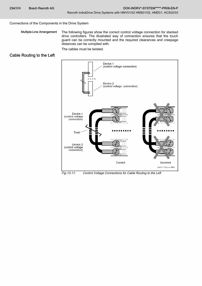
Multiple-Line Arrangement The following figures show the correct control voltage connection for stackeddrive controllers. The illustrated way of connection ensures that the touchguard can be correctly mounted and the required clearances and creepagedistances can be complied with.The cables must be twisted.
Cable Routing to the Left
Fig.13-11: Control Voltage Connections for Cable Routing to the Left
Bosch Rexroth AG DOK-INDRV*-SYSTEM*****-PR06-EN-P Rexroth IndraDrive Drive Systems with HMV01/02 HMS01/02, HMD01, HCS02/03
234/309
Connections of the Components in the Drive System
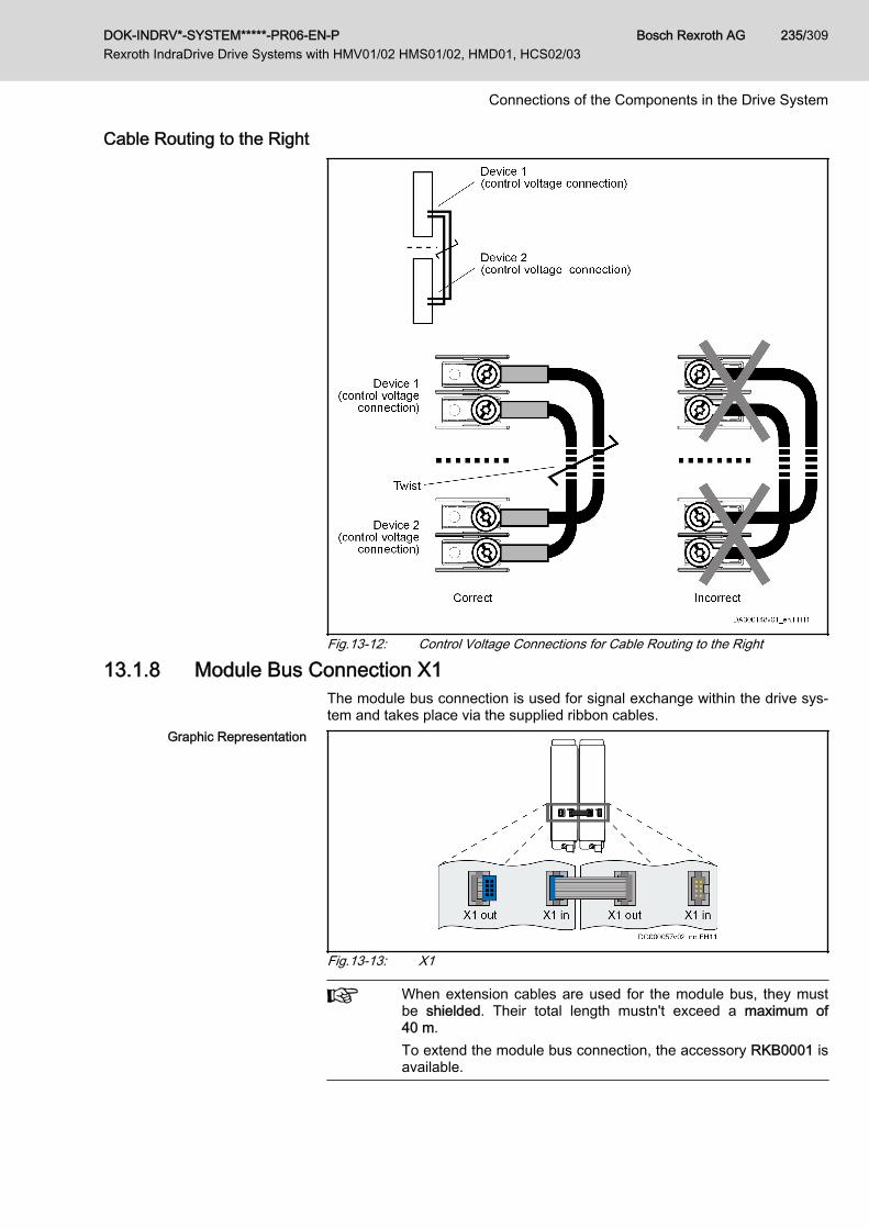
Cable Routing to the Right
Fig.13-12: Control Voltage Connections for Cable Routing to the Right
13.1.8 Module Bus Connection X1The module bus connection is used for signal exchange within the drive sys‐tem and takes place via the supplied ribbon cables.
Graphic Representation
Fig.13-13: X1
When extension cables are used for the module bus, they mustbe shielded. Their total length mustn't exceed a maximum of40 m.To extend the module bus connection, the accessory RKB0001 isavailable.
DOK-INDRV*-SYSTEM*****-PR06-EN-P Rexroth IndraDrive Drive Systems with HMV01/02 HMS01/02, HMD01, HCS02/03
Bosch Rexroth AG 235/309
Connections of the Components in the Drive System
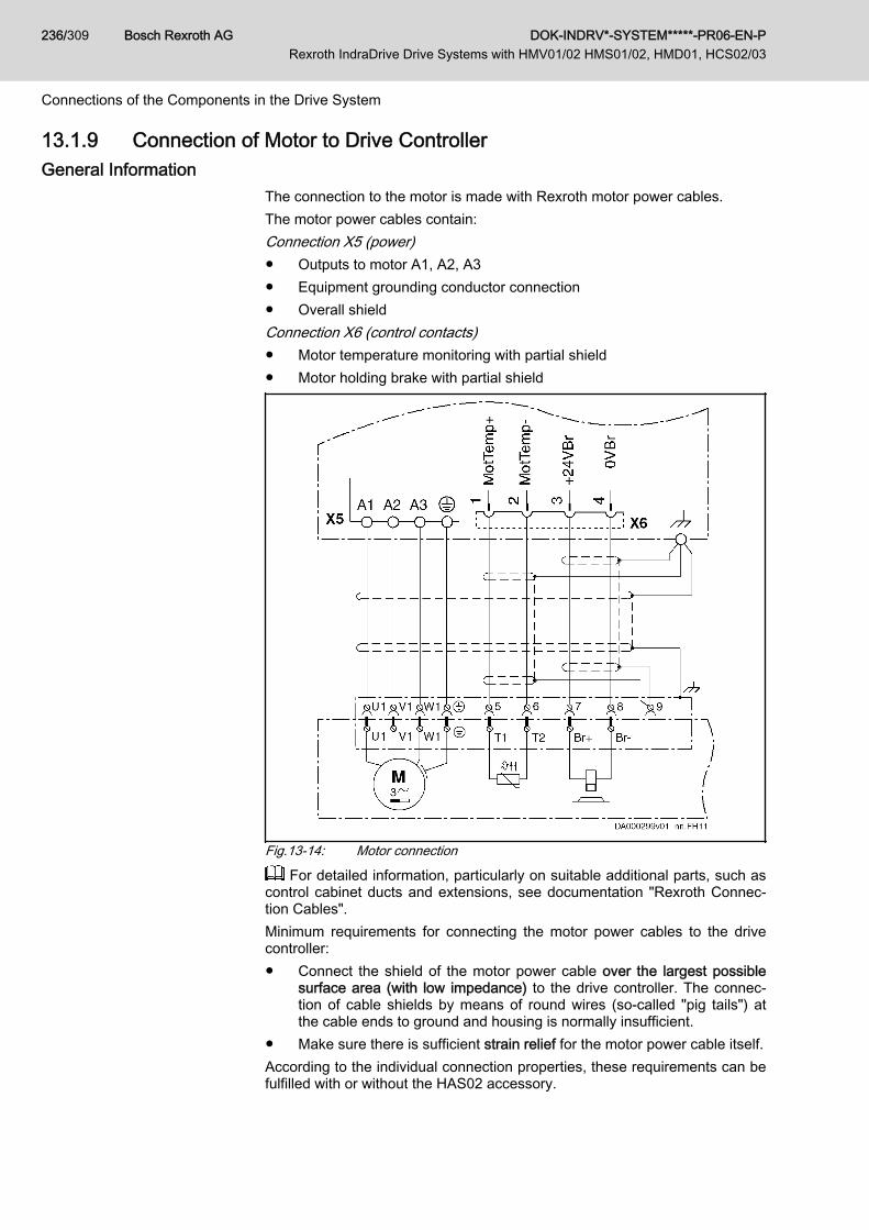
13.1.9 Connection of Motor to Drive ControllerGeneral Information
The connection to the motor is made with Rexroth motor power cables.The motor power cables contain:Connection X5 (power)● Outputs to motor A1, A2, A3● Equipment grounding conductor connection● Overall shieldConnection X6 (control contacts)● Motor temperature monitoring with partial shield● Motor holding brake with partial shield
Fig.13-14: Motor connection
For detailed information, particularly on suitable additional parts, such ascontrol cabinet ducts and extensions, see documentation "Rexroth Connec‐tion Cables".Minimum requirements for connecting the motor power cables to the drivecontroller:● Connect the shield of the motor power cable over the largest possible
surface area (with low impedance) to the drive controller. The connec‐tion of cable shields by means of round wires (so-called "pig tails") atthe cable ends to ground and housing is normally insufficient.
● Make sure there is sufficient strain relief for the motor power cable itself.According to the individual connection properties, these requirements can befulfilled with or without the HAS02 accessory.
Bosch Rexroth AG DOK-INDRV*-SYSTEM*****-PR06-EN-P Rexroth IndraDrive Drive Systems with HMV01/02 HMS01/02, HMD01, HCS02/03
236/309
Connections of the Components in the Drive System

Shield Connection with Accessory HAS02Using the optional accessory HAS02 with connection over a large surfacearea directly to the device is the best solution for shield connection. The fig‐ure below illustrates this by the example of HCS02 drive controllers:
Fig.13-15: Connecting HAS02 to HCS02
For information on the available accessory HAS02 and how to mount it,see Project Planning Manual "Rexroth IndraDrive Additional Componentsand Accessories".
Shield Connection without Accessory HAS02For shield connection without HAS02 accessory, connect the cable shieldwith the lowest possible impedance to the drive controller.The following paragraphs describe two basic alternatives of this kind of con‐nection.
Alternative 1 Connect cable shield to a ground bus. The maximum distance betweenground bus and device connection is 100 mm. For this purpose, take the giv‐en length of the single strands at the cable end into account for ready-madeRexroth motor power cables.
DOK-INDRV*-SYSTEM*****-PR06-EN-P Rexroth IndraDrive Drive Systems with HMV01/02 HMS01/02, HMD01, HCS02/03
Bosch Rexroth AG 237/309
Connections of the Components in the Drive System

1 Drive controller2 Clip for shield contact3 Overall shield of the motor power cable folded back4 Ground bus in control cabinet5 Single strands of motor power cable6 Connection of ground bus to supplying device7 Strain relief (as near as possible to exit point from control cabinet)Fig.13-16: Shield Connection, Alternative 1● With a clip (2), connect overall shield of motor power cable (3) to ground
bus (4). (If you use your own cable, make sure the shields of the two in‐ner pairs of wires are in contact with the overall shield.)
● With a cable (6) (line cross section: at least 10 mm2), connect groundbus (4) to ground connection at supplying device (Rexroth IndraDrivesupply unit or Rexroth IndraDrive drive controller HCS).
Alternative 2 Connect cable shield to a ground bus. The cable length between device andground bus mustn't be more than a maximum of 1 m. For this purpose, pre‐pare the motor cable in accordance with the description below:
Bosch Rexroth AG DOK-INDRV*-SYSTEM*****-PR06-EN-P Rexroth IndraDrive Drive Systems with HMV01/02 HMS01/02, HMD01, HCS02/03
238/309
Connections of the Components in the Drive System

1 Drive controller2 Cable tie3 Overall shield of the motor power cable folded back4 Ground bus in control cabinet5 Connection between overall shield of motor power cable laying bare
and ground bus6 Connection of ground bus to supplying device7 Strain relief (as near as possible to the drive-side cable end)8 Strain relief (as near as possible to exit point from control cabinet)A Cable length between ground bus and device: < 1 mFig.13-17: Shield Connection, Alternative 2● With a cable tie (2), press drive-side cable end in such a way that
shields of two inner pairs of wires (motor temperature, holding brake)have good contact with overall shield of motor power cable (3). (If youuse your own cable, make sure the shields of the two inner pairs ofwires are in contact with the overall shield.)
● On level of ground bus in control cabinet, remove a piece of cablesheath from motor power cable in order to lay bare the overall shield (5).
● Connect overall shield (5) to ground bus in control cabinet with an ap‐propriate connection (clip). The connection must have a cross section ofat least 10 mm2.
● With a cable (6) (line cross section: at least 10 mm2), connect groundbus (4) to ground connection at supplying device (Rexroth IndraDrivesupply unit or Rexroth IndraDrive drive controller HCS).
● Make sure there is sufficient strain relief for motor power cable as nearas possible to drive-side cable end (7).
● In addition, make sure there is sufficient strain relief for motor power ca‐ble as near as possible to exit point from control cabinet of motor powercable (8).
DOK-INDRV*-SYSTEM*****-PR06-EN-P Rexroth IndraDrive Drive Systems with HMV01/02 HMS01/02, HMD01, HCS02/03
Bosch Rexroth AG 239/309
Connections of the Components in the Drive System

Do not remove the shield of the motor cable between ground busand device.
If the motor power cables are routed to the control cabinet via flange sockets,directly connect the shield to the wall of the control cabinet over a large sur‐face area via the housing of the flange socket. Make sure there is sufficientseparate strain relief.
Bonding Conductor Bad ground connection between motor housing and control cabinet housing,as well as long motor cables, can require additional routing of a bonding con‐ductor of a cross section of normally 10 mm2 between control cabinet hous‐ing and motor housing.
For cable lengths of more than 50 m, the cross section should beat least 35 mm2.
Shield Connection of Kit Motors For kit motors, make sure that the connection lines are run in shielded formor under metal between winding and terminal box, if the terminal box is notdirectly mounted on the spindle case.
Shield Connection of Linear Mo‐tors
For linear motors, connect the shield of the connection cable between pri‐mary part and terminal box via clips to machine housing or metal shell.
Shielding of Motor TemperatureMonitoring and Motor Holding
Brake
The inner shields of motor temperature monitor and motor holding brake inthe motor cable are connected to the drive controller at one end.
13.2 Overall Connection Diagrams of Drive SystemsOverall connection diagrams of Rexroth IndraDrive systems: See chapter 9 "Circuits for the Mains Connection" on page 141.To draw up the overall connection diagrams there are ePlan macros of thedevices available. Please ask our sales representative.
Bosch Rexroth AG DOK-INDRV*-SYSTEM*****-PR06-EN-P Rexroth IndraDrive Drive Systems with HMV01/02 HMS01/02, HMD01, HCS02/03
240/309
Connections of the Components in the Drive System

14 Third-Party Motors at Rexroth IndraDrive Controllers14.1 General Information on Third-Party Motors14.1.1 Why Use Third-Party Motors at Rexroth IndraDrive Controllers?
Today, machine axes are mainly moved with electric drives. Motors of stand‐ard design are used in most cases, as this is the most cost-efficient solution.
Special Requirements Due to special requirements at machine axes, constructional or safety-relatedaspects, it may be necessary for the machine manufacturer to use a motorconstruction diverging from the standard.
Motor Designs not Included inProduct Range
For these cases, there is the demand on drive suppliers to realize drives withmotors that are not included in their own product ranges due to the specialdesign.
Check Before Using Third-PartyMotors
At drive controllers of the Rexroth IndraDrive range, it is possible to use third-party motors. For this purpose, check whether the third-party motor complieswith the requirements of use.The Functional Description of the firmware contains forms for motor data.Procure the completed forms for the performance test of a third-party motor.
14.1.2 Which are the Important Directives?In accordance with the legal regulations (EU Directive EMC 89/336/EEC andthe German EMC laws), installations and machines must be designed andbuilt in accordance with the present state-of-the-art of standardization.In order to comply with the machine directives regarding "electromagneticcompatibility (EMC)", a conformity test of the drive system (motor with con‐troller and connection design) must be carried out. The machine manufactur‐er must guarantee the test of the drive system and compliance with the direc‐tives.
14.1.3 Third-Party Motors to be ControlledMotor Types The following motor types can be controlled:
● Asynchronous motors, rotary● Asynchronous motors, linear● Synchronous motors, rotary● Synchronous motors, linearThese motors can be operated within the scope of the technical data of theselected Rexroth IndraDrive controller. If motors have been provided with aholding brake, it should be controlled via the drive controller. Make sure thatthe relevant technical data of the motor holding brake are complying withthose of the holding brake output!
For third-party motors Rexroth, as a matter of principle, does notassume the guarantee for the power data at the motor shaft!
Synchronous Motors For synchronous motors, the commutation offset must be set during commis‐sioning. The drive firmware provides several methods for determining this off‐set so that it is possible to determine the value for different motor characteris‐tics.
DOK-INDRV*-SYSTEM*****-PR06-EN-P Rexroth IndraDrive Drive Systems with HMV01/02 HMS01/02, HMD01, HCS02/03
Bosch Rexroth AG 241/309
Third-Party Motors at Rexroth IndraDrive Controllers

Observe the restrictions in conjunction with the commutation off‐set determination when using synchronous motors! See firmwaredocumentation, chapter "Drive Control", "Commutation Setting".Possibly available reluctance property cannot be used for syn‐chronous third-party motors! For third-party motors, it is impossi‐ble to determine fail-safe motor parameter values for using the re‐luctance property. The respective bit of "P‑0‑4014, Type of con‐struction of motor" therefore mustn't be set!
14.2 Requirements on Third-Party Motors14.2.1 General Information
For successful and fail-safe use of a third-party motor, check● whether the third-party motor to be controlled satisfies the voltage loads● which controller, including supply, is suitable due to the motor power to
be delivered● whether the third-party motor has the required minimum inductance● whether the motor can be protected against inadmissible temperature
rise in the case of overload (temperature evaluation)● whether the mounted position measuring system can be evaluated by
the drive controller or which position measuring system can be selectedfor kit motors
14.2.2 Voltage Load of the Third-Party MotorThe voltage load of the insulation system of a motor occurring in practical ap‐plication is mainly influenced by the following characteristics:● The output variables of the drive controller which is used (feed the trans‐
mission distance)● Cable parameters depending on cable design and length (determine the
properties of the transmission distance, such as the attenuation)● The motor design regarding capacitive and inductive properties (form
the end of the transmission distance)As a result of the variables, the insulation system of the third-party motor, asregards voltage, is loaded by the following values:● Peak voltage Upp and● Voltage change dv/dtThe occurring peak voltages at the motor are caused by reflections in the mo‐tor cable. The insulation of the motor is thereby loaded with other peak vol‐tages and voltage changes than the ones occurring at the output of the pow‐er section.
Determine the occurring voltage load at the terminals of the third-party motor in the application with all involved components.
Using the HMF Motor Filter Use voltage-reducing components (e.g. motor filter HMF), if one of the follow‐ing criteria applies:● Allowed voltage change (dv/dt) of third-party motor: < 5 kV/μs● Allowed peak voltage (crest value) of third-party motor between phase-
phase and phase-housing: < 1,500 V
Bosch Rexroth AG DOK-INDRV*-SYSTEM*****-PR06-EN-P Rexroth IndraDrive Drive Systems with HMV01/02 HMS01/02, HMD01, HCS02/03
242/309
Third-Party Motors at Rexroth IndraDrive Controllers

● Both values (voltage change, peak voltage) are influenced by:– DC bus voltage:
The higher the DC bus voltage at which the drive system is operat‐ed, the higher the value of the voltage change and the occurringpeak voltage.
– Length and electrical properties of the motor cable:The shorter the motor cable, the less the attenuation effects.The longer the motor cable, the higher the degree of voltage over‐shoot at the motor-side cable end.
– For a motor cable length l < 25 m and mains voltageUN3 > AC 440 V, it is recommended that you use voltage-reducingcomponents.
Apart from the nominal current IN, especially take the maximumallowed switching frequency of the power output stage (fs) into ac‐count with which the motor filter HMF may be operated.Verify the success of the voltage-reducing measures.
14.2.3 Minimum Inductance of Third-Party MotorDepending on the drive controller used, the motor has to have a minimumvalue for inductance. The actually available inductance of a motor can bemeasured directly between two motor terminals by means of an inductancemeasuring bridge. The measurement has to be made for a complete motorwired for normal operation but not yet connected. During the measurement,one motor terminal remains open! For asynchronous motors, the measuredvalue can only be used if the rotor doesn't have closed slots!
Drive controller Minimum required motor inductance
HCS at 3 × AC 230 V LU-V = 60 × 4 / (√2 × ITyp × fs) (in mH)
HMS, HMD at HMV (3 × AC 400 V)HMS, HMD at HCS (3 × AC 400 V)HCS at 3 × AC 400 V
LU-V = 80 × 4 / (√2 × ITyp × fs) (in mH)
HMS, HMD at HMV (3 × AC 480 V)HMS, HMD at HCS (3 × AC 480 V)HCS at 3 × AC 480 V
LU-V = 116 × 4 / (√2 × ITyp × fs) (in mH)
ITyp Maximum current of drive controller according to type code (rms val‐ue)
fs Desired switching frequency in kHzTab.14-1: Minimum Inductances Depending on Drive Controller Data, Supply
Units and Supply VoltageInstall a three-phase choke in the motor feed wire, if the inductance of thethird-party motor is smaller than indicated in the table above. This choke hasto increase the inductance that can be measured between two motor termi‐nals to the minimum value.
DOK-INDRV*-SYSTEM*****-PR06-EN-P Rexroth IndraDrive Drive Systems with HMV01/02 HMS01/02, HMD01, HCS02/03
Bosch Rexroth AG 243/309
Third-Party Motors at Rexroth IndraDrive Controllers
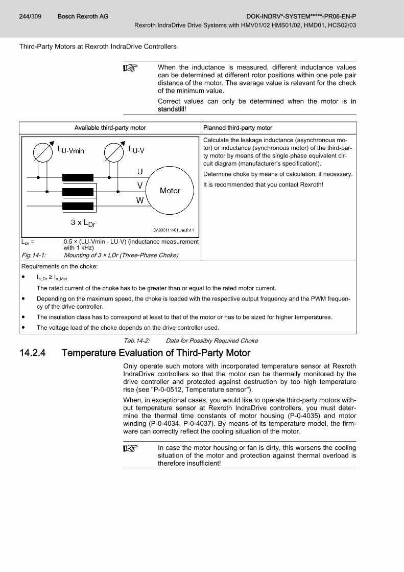
When the inductance is measured, different inductance valuescan be determined at different rotor positions within one pole pairdistance of the motor. The average value is relevant for the checkof the minimum value.Correct values can only be determined when the motor is instandstill!
Available third-party motor Planned third-party motor
LDr = 0.5 × (LU-Vmin - LU-V) (inductance measurementwith 1 kHz)
Fig.14-1: Mounting of 3 × LDr (Three-Phase Choke)
Calculate the leakage inductance (asynchronous mo‐tor) or inductance (synchronous motor) of the third-par‐ty motor by means of the single-phase equivalent cir‐cuit diagram (manufacturer's specification!).Determine choke by means of calculation, if necessary.It is recommended that you contact Rexroth!
Requirements on the choke:● In_Dr ≥ In_Mot
The rated current of the choke has to be greater than or equal to the rated motor current.● Depending on the maximum speed, the choke is loaded with the respective output frequency and the PWM frequen‐
cy of the drive controller.● The insulation class has to correspond at least to that of the motor or has to be sized for higher temperatures.● The voltage load of the choke depends on the drive controller used.
Tab.14-2: Data for Possibly Required Choke
14.2.4 Temperature Evaluation of Third-Party MotorOnly operate such motors with incorporated temperature sensor at RexrothIndraDrive controllers so that the motor can be thermally monitored by thedrive controller and protected against destruction by too high temperaturerise (see "P‑0‑0512, Temperature sensor").When, in exceptional cases, you would like to operate third-party motors with‐out temperature sensor at Rexroth IndraDrive controllers, you must deter‐mine the thermal time constants of motor housing (P‑0‑4035) and motorwinding (P‑0‑4034, P‑0‑4037). By means of its temperature model, the firm‐ware can correctly reflect the cooling situation of the motor.
In case the motor housing or fan is dirty, this worsens the coolingsituation of the motor and protection against thermal overload istherefore insufficient!
Bosch Rexroth AG DOK-INDRV*-SYSTEM*****-PR06-EN-P Rexroth IndraDrive Drive Systems with HMV01/02 HMS01/02, HMD01, HCS02/03
244/309
Third-Party Motors at Rexroth IndraDrive Controllers

14.3 Requirements on the Encoder of the Third-Party Motor14.3.1 Motor Encoder of Asynchronous Third-Party Motor
Asynchronous motors can also be controlled by Rexroth IndraDrive control‐lers in "open-loop" operation (without motor encoder). In "closed-loop" opera‐tion (with motor encoder), a relative measuring system is sufficient for asyn‐chronous motors.
14.3.2 Motor Encoder of Synchronous Third-Party MotorFor fail-safe drives with synchronous third-party motors at Rexroth IndraDrivecontrollers, the following possible combinations or restrictions have to be tak‐en into account when selecting the measuring system:
Drive range Motor measuring system Synchronous third-partymotor
Rexroth IndraDriveAbsolute ■
Relative □
■ Advantageous combination□ Combination is possible (restrictions specific to application), commis‐
sioning may be more complicated!Tab.14-3: Possible Combinations of Synchronous Third-Party Motor and Motor
Measuring System
The control section integrated in the drive controller can evaluatemeasuring systems as a motor encoder, if they are contained in"P‑0‑0074, Encoder type 1 (motor encoder)" (see also ProjectPlanning Manual "Rexroth IndraDrive Drive Controllers ControlSections").For information on absolute and relative measuring systems, seesection "Measuring Systems" of firmware documentation!
14.3.3 Motor Encoder Resolver - Notes on SelectionFor operating "resolver" encoder types, there is the optional module EN1available (see also Project Planning Manual "Rexroth IndraDrive Drive Con‐trollers Control Sections").Observe:● Data of resolver system to be compared must be available at 4 kHz● Ratio● Current consumption● DC resistance of stator● Number of poles● Phase shiftYou can get more detailed information on request.
14.4 Notes on Selection and Commissioning14.4.1 Selecting the Controller as Regards Continuous Current
The drive controller required for the respective motor and the supply unit aredetermined by comparing the motor data to the data of these devices (see
DOK-INDRV*-SYSTEM*****-PR06-EN-P Rexroth IndraDrive Drive Systems with HMV01/02 HMS01/02, HMD01, HCS02/03
Bosch Rexroth AG 245/309
Third-Party Motors at Rexroth IndraDrive Controllers
Project Planning Manual "Rexroth IndraDrive Supply Units and Power Sec‐tions").
The continuous current of the drive controller should be greaterthan the one of the motor. The continuous power of the supplymust be greater than the sum of all average powers of the axes ofthe drive system!
14.4.2 Selecting the Connection TechniqueFor the available power cables and encoder cables, see documentation"Rexroth Connection Cables".
14.4.3 Notes on Commissioning
For further information, notes on commissioning and supportingdocuments (e.g., forms for entering the required data) see firm‐ware documentation.
Bosch Rexroth AG DOK-INDRV*-SYSTEM*****-PR06-EN-P Rexroth IndraDrive Drive Systems with HMV01/02 HMS01/02, HMD01, HCS02/03
246/309
Third-Party Motors at Rexroth IndraDrive Controllers

15 Calculations15.1 Determining the Appropriate Drive Controller15.1.1 Introduction
Supply for the drive system Rexroth IndraDrive takes place by means of com‐pact HCS converters or HMV supply units. According to the drive task, designof drive controller and operating conditions, chokes, additional capacitors,braking resistors, transformers, etc., may be required.The drive controller or supply unit has to supply the DC bus continuous pow‐er and for acceleration the DC bus peak power. With regenerative operation,they must be able to absorb the continuous recovery power and peak recov‐ery power.Before the drive controller or supply unit and the additional components canbe selected, the motors and drive controllers to be used must be defined.To ensure correct sizing of the drive system, you should do the calculationsin the order described in the following chapters.
15.1.2 DC Bus Continuous PowerThe DC bus continuous power is calculated from the mechanical power, tak‐ing the following aspects into consideration:● Motor and controller efficiency● Simultaneity Factors
Mechanical Power
Pm Mechanical powerM Torque [Nm]ω Angular velocity [min-1]n Motor speed [min-1]Fig.15-1: Mechanical Power
Mechanical Continuous Power forServo Drives
To calculate the mechanical continuous power of a servo drive, you need theeffective motor torque and the average motor speed.The effective motor torque can be taken from the servo drive calculation. Theaverage motor speed is determined as follows:
Average Motor Speed For servo drive tasks at common NC machine tools, the average motorspeed is approx. 25% of the rapid traverse speed. In some cases, however,this rough estimation is not sufficient. An exact calculation of the average mo‐tor speed is required.
Average Speed With Run-Up andBraking Times not Taken Into Ac‐
count
If the period during which the motor is run at constant speed is significantlygreater than the run-up and braking time, the following applies:
DOK-INDRV*-SYSTEM*****-PR06-EN-P Rexroth IndraDrive Drive Systems with HMV01/02 HMS01/02, HMD01, HCS02/03
Bosch Rexroth AG 247/309
Calculations

nav Average motor speed [min-1]n1 ... nn Motor speed [min-1]t1 ... tn Duty cycle [s]Fig.15-2: Average Speed; Effects of Run-Up and Braking Times not Taken Into
Account
Fig.15-3: Speed Characteristic; Effects of Run-Up and Braking Times not TakenInto Account
In dynamic applications with short cycle times, e.g. roll feeds and nibblingmachines, run-up and braking times must be taken into account.
Damage to the drive controller!NOTICE● The DC bus capacitors in the drive controller have been dimensioned
for loading with continuous power.● If loaded with cyclic charging and discharging processes of high energy
content, the DC bus capacitors can be overloaded, especially with de‐creasing mains connection voltage.
Operate additional capacitors at the DC bus.
Average Speed With Run-Up andBraking Times Taken Into Account
nav Average motor speed [min-1]n Motor speed [min-1]t Time [s]tH Run-up time [s]tB Braking time [s]Fig.15-4: Average Speed; Effects of Run-Up and Braking Times Taken Into Ac‐
count
Bosch Rexroth AG DOK-INDRV*-SYSTEM*****-PR06-EN-P Rexroth IndraDrive Drive Systems with HMV01/02 HMS01/02, HMD01, HCS02/03
248/309
Calculations

Fig.15-5: Average Speed; Effects of Run-Up and Braking Times Taken Into Ac‐count
Mechanical Power for ServoDrives
PmSe Mechanical continuous power for servo drives [kW]Mrms Effective motor torque [Nm]nav Average motor speed [min-1]Fig.15-6: Mechanical Power for Servo Drives
Mechanical Power for Main Drives Main drives are drives which are mainly used in the constant power speedrange. Thus, nominal power is decisive for sizing the mains supply. The me‐chanical nominal power of the main drives can be taken from the operatingcharacteristic or calculated from nominal speed and nominal torque.
PmHa Mechanical nominal power for main drives (shaft output) [kW]Mn Nominal motor torque [Nm]nn Nominal motor speed [min-1]Fig.15-7: Mechanical Power for Main Drives
DC Bus Continuous Power forServo Drives
The drive controller or the group of drive controllers has to make available theDC bus power. However, in most applications, simultaneous loading of alldrives will not occur; thus, only the simultaneously occurring power must beconsidered for calculating the DC bus continuous power to be made availablefor servo drives. To calculate the DC bus continuous power to be made avail‐able for typical NC feed axes at machine tools, inclusion of a so-called simul‐taneity factor has proved to be favorable in practical application:
Number of ax‐es 1 2 3 4 5 6 7 n = n + 1
Simultaneityfactor (FG) 1 1,15 1,32 1,75 2,0 2,25 FG=2,5 FGn = FG + 0,25
Tab.15-1: Simultaneity Factors
DOK-INDRV*-SYSTEM*****-PR06-EN-P Rexroth IndraDrive Drive Systems with HMV01/02 HMS01/02, HMD01, HCS02/03
Bosch Rexroth AG 249/309
Calculations
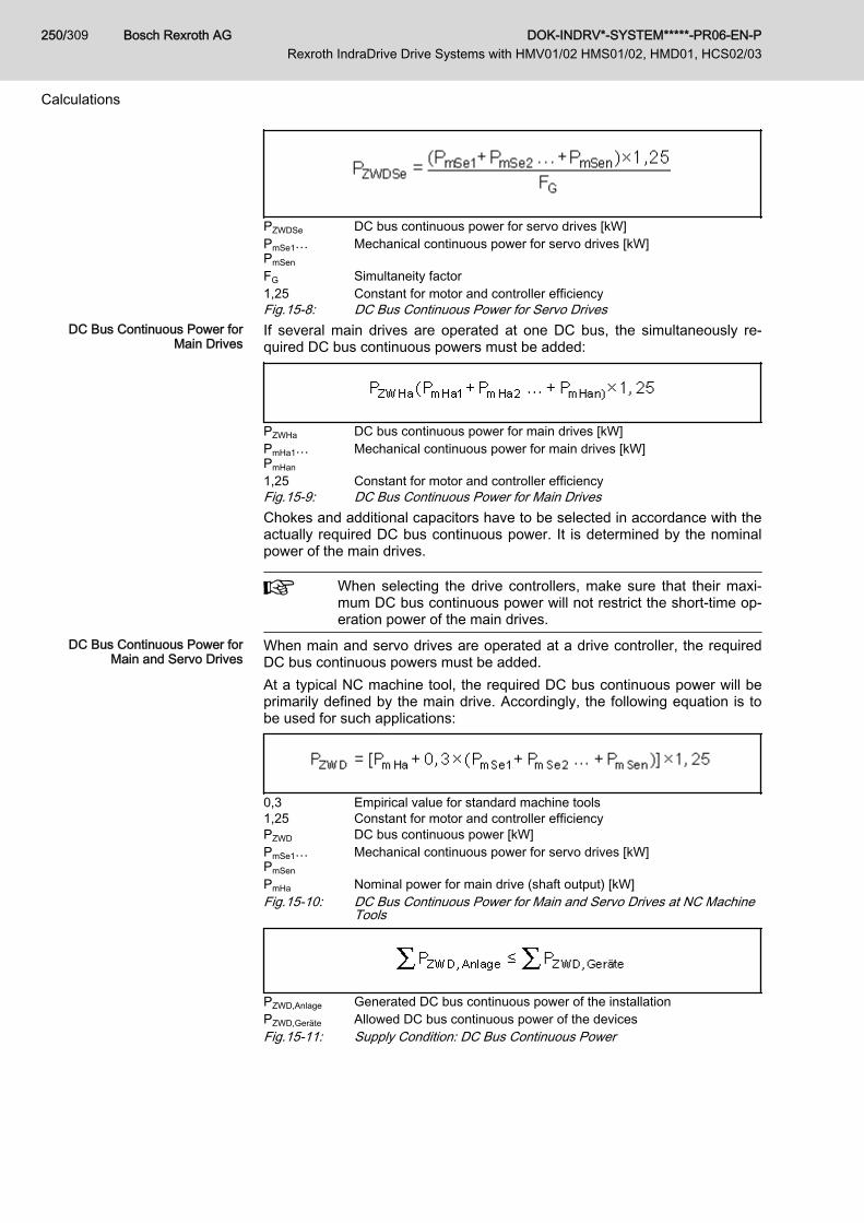
PZWDSe DC bus continuous power for servo drives [kW]PmSe1…PmSen
Mechanical continuous power for servo drives [kW]
FG Simultaneity factor1,25 Constant for motor and controller efficiencyFig.15-8: DC Bus Continuous Power for Servo Drives
DC Bus Continuous Power forMain Drives
If several main drives are operated at one DC bus, the simultaneously re‐quired DC bus continuous powers must be added:
PZWHa DC bus continuous power for main drives [kW]PmHa1…PmHan
Mechanical continuous power for main drives [kW]
1,25 Constant for motor and controller efficiencyFig.15-9: DC Bus Continuous Power for Main DrivesChokes and additional capacitors have to be selected in accordance with theactually required DC bus continuous power. It is determined by the nominalpower of the main drives.
When selecting the drive controllers, make sure that their maxi‐mum DC bus continuous power will not restrict the short-time op‐eration power of the main drives.
DC Bus Continuous Power forMain and Servo Drives
When main and servo drives are operated at a drive controller, the requiredDC bus continuous powers must be added.At a typical NC machine tool, the required DC bus continuous power will beprimarily defined by the main drive. Accordingly, the following equation is tobe used for such applications:
0,3 Empirical value for standard machine tools1,25 Constant for motor and controller efficiencyPZWD DC bus continuous power [kW]PmSe1…PmSen
Mechanical continuous power for servo drives [kW]
PmHa Nominal power for main drive (shaft output) [kW]Fig.15-10: DC Bus Continuous Power for Main and Servo Drives at NC Machine
Tools
PZWD,Anlage Generated DC bus continuous power of the installationPZWD,Geräte Allowed DC bus continuous power of the devicesFig.15-11: Supply Condition: DC Bus Continuous Power
Bosch Rexroth AG DOK-INDRV*-SYSTEM*****-PR06-EN-P Rexroth IndraDrive Drive Systems with HMV01/02 HMS01/02, HMD01, HCS02/03
250/309
Calculations

15.1.3 DC Bus Peak PowerThe drive controller or combination of drive controllers has to produce DCbus peak power for example when several axes of a machine tool simultane‐ously accelerate to rapid traverse rate after a tool change, approaching theworkpiece.
Damage due to supply unit overload!NOTICETo avoid damage to the drive controller, the sum of peak powers of all drivesmustn't exceed the DC bus peak power of the supplying drive controller (cen‐tral supply).
MNC Acceleration torque in the drive [Nm]MG Torque due to weight for vertical axes [Nm]neil Speed at rapid traverse rate [min-1]PZWS DC bus peak power [kW]1,25 Constant for motor and controller efficiencyFig.15-12: DC Bus Peak Power per Drive
PZWS,Anlage Generated DC bus peak power of the installationPZWS,Geräte Allowed DC bus peak power of the devicesFig.15-13: Supply Condition: DC Bus Peak Power
15.1.4 Regenerative PowerWhen all main and servo drives connected to a drive controller or combina‐tion of drive controllers brake simultaneously, the generated regenerativepower must not be greater than the maximum regenerative power of the drivecontroller or combination of drive controllers. If this is not taken into consider‐ation in sizing the system, thermal destruction of the braking resistors in thedrive controllers may occur.
Destruction due to braking resistor overload!NOTICEDo the project planning for drive controllers or combinations of drive control‐lers in such a way that the resulting regenerative power can be absorbedwhen all main and servo drives connected to the drive controller or combina‐tion of drive controllers brake simultaneously.
Wrot Rotary energy [Ws]neil Speed at rapid traverse rate [min-1]JG Motor inertia and load inertia reduced to the motor shaft [kgm²]Fig.15-14: Regenerative Power per Drive
DOK-INDRV*-SYSTEM*****-PR06-EN-P Rexroth IndraDrive Drive Systems with HMV01/02 HMS01/02, HMD01, HCS02/03
Bosch Rexroth AG 251/309
Calculations
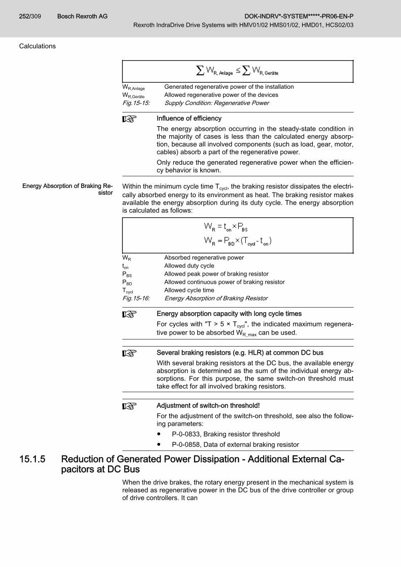
WR,Anlage Generated regenerative power of the installationWR,Geräte Allowed regenerative power of the devicesFig.15-15: Supply Condition: Regenerative Power
Influence of efficiencyThe energy absorption occurring in the steady-state condition inthe majority of cases is less than the calculated energy absorp‐tion, because all involved components (such as load, gear, motor,cables) absorb a part of the regenerative power.Only reduce the generated regenerative power when the efficien‐cy behavior is known.
Energy Absorption of Braking Re‐sistor
Within the minimum cycle time Tcycl, the braking resistor dissipates the electri‐cally absorbed energy to its environment as heat. The braking resistor makesavailable the energy absorption during its duty cycle. The energy absorptionis calculated as follows:
WR Absorbed regenerative powerton Allowed duty cyclePBS Allowed peak power of braking resistorPBD Allowed continuous power of braking resistorTcycl Allowed cycle timeFig.15-16: Energy Absorption of Braking Resistor
Energy absorption capacity with long cycle timesFor cycles with "T > 5 × Tcycl", the indicated maximum regenera‐tive power to be absorbed WR_max can be used.
Several braking resistors (e.g. HLR) at common DC busWith several braking resistors at the DC bus, the available energyabsorption is determined as the sum of the individual energy ab‐sorptions. For this purpose, the same switch-on threshold musttake effect for all involved braking resistors.
Adjustment of switch-on threshold!For the adjustment of the switch-on threshold, see also the follow‐ing parameters:● P-0-0833, Braking resistor threshold● P-0-0858, Data of external braking resistor
15.1.5 Reduction of Generated Power Dissipation - Additional External Ca‐pacitors at DC Bus
When the drive brakes, the rotary energy present in the mechanical system isreleased as regenerative power in the DC bus of the drive controller or groupof drive controllers. It can
Bosch Rexroth AG DOK-INDRV*-SYSTEM*****-PR06-EN-P Rexroth IndraDrive Drive Systems with HMV01/02 HMS01/02, HMD01, HCS02/03
252/309
Calculations

● be converted into dissipation heat via the braking resistor integrated inthe drive controller or the additional braking resistor
or● be stored as energy in the drive controllers and possibly available addi‐
tional capacitors and reused for following acceleration processes. Thisreduces the power dissipation generated in the control cabinet and low‐ers the energy consumption.
The following applies to successful use of additional capacitors to avoid un‐necessary power dissipation in the control cabinet:
WR,Anlage Generated regenerative power of the installationWZW,Geräte Storable energy of the DC bus capacitorsFig.15-17: Condition to Avoid Power Dissipation From the Regenerative Power
Additional Capacitors as EnergyStores
Many acceleration and deceleration processes are typical for applicationswith servo drives (e.g. nibbling machines or roll feeds). This is why it can beuseful for such applications to connect additional capacitors to the DC bus ofthe drive controllers. This provides the following advantages:● For drive controllers without mains regeneration function, this prevents
the braking resistor in the drive controller from being switched on whenthe drives brake. The dissipation heat in the control cabinet is consider‐ably reduced.
● The energy stored in the DC bus capacitors can be used for accelera‐tion. The energy demand of the installation is reduced.
Storable Energy in DC Bus The specific energy absorption capacity of the drive controllers can be deter‐mined with the formula below.
WDC Storable energy in DC busCDC DC bus capacitance in device [F]CDCext External DC bus capacitance [F]UR_DC On Braking resistor switch-on thresholdUDC DC bus voltageFig.15-18: Storable Energy in DC BusThe additional capacitor has to be sized in such a way that it can store therotary drive energy:
UR_DC On Braking resistor switch-on thresholdUDC DC bus voltageWrot Rotary energy [Ws]CDC Internal capacitance [F]CDCext Required external DC bus capacitance [F]Fig.15-19: Required Additional Capacitance [F]
DOK-INDRV*-SYSTEM*****-PR06-EN-P Rexroth IndraDrive Drive Systems with HMV01/02 HMS01/02, HMD01, HCS02/03
Bosch Rexroth AG 253/309
Calculations
Property damage caused by overload of HMVand HCS devices!
NOTICE
Comply with maximum allowed external DC bus capacitances! See electricaldata of the HMV and HCS components.
Property damage caused by overload of theadditional external capacitors!
NOTICE
● Only use allowed components.● The properties of the additional capacitors have to comply with minimum
requirements:
– Min. dielectric strength: DC 900 V– Max. discharge time: 30 min– Take measures against fire in the case of overload, e.g. by housing
the capacitors.● Connect correct polarity: Connect L+ to positive pole and L- to negative
pole of the additional capacitors.
● For additional external capacitors, observe that the seriesconnection of these units can require a balancing device.
● Size additional capacitors at the DC bus for 10% overvoltageat the mains connection.
● As the supply voltage increases the storable energy in theDC bus decreases, because the differential voltage betweenbraking resistor switch-on threshold UB and DC bus voltageUZW (crest value of supply voltage) is reduced.
● Take the service life of external capacitors into account.
The figure below illustrates the characteristic of the storable energy in the DCbus versus mains voltage with fixed braking resistor switch-on threshold UBby the example of HCS02.1E devices.
Bosch Rexroth AG DOK-INDRV*-SYSTEM*****-PR06-EN-P Rexroth IndraDrive Drive Systems with HMV01/02 HMS01/02, HMD01, HCS02/03
254/309
Calculations

Fig.15-20: Storable Energy in DC Bus
15.1.6 Continuous Regenerative Power
In terms of average period of time, the sum of the continuous re‐generative power of all drives mustn't exceed the allowed continu‐ous power of the regenerative device (regeneration of supplyunits or braking resistors of converters).
In applications with servo drives at typical NC machine tools, machining timeis relatively long relative to the cycle time. Accordingly, the continuous regen‐erative powers are small. For this type of applications, exact calculation is notrequired. It is sufficient to make sure that the regenerative peak power is notexceeded.Exact calculation is required, for example, for one of the following applica‐tions:● Applications with servo drives which are characterized by many acceler‐
ation and deceleration processes (e.g. nibbling machines or roll feeds)● Machine tools with modular main drive● Applications which involve lowering of large masses, e.g. loading
bridges, warehousing and transport systemsBefore the continuous regenerative power can be calculated, the rotary ener‐gy of the drives and the potential energy of non-balanced masses must becalculated.
Wrot Rotary energy [Ws]neil Speed at rapid traverse rate [min-1]Jg Inertia (motor + load) [kgm²]z Number of braking processes per cycleFig.15-21: Rotary Energy of the Drives
DOK-INDRV*-SYSTEM*****-PR06-EN-P Rexroth IndraDrive Drive Systems with HMV01/02 HMS01/02, HMD01, HCS02/03
Bosch Rexroth AG 255/309
Calculations
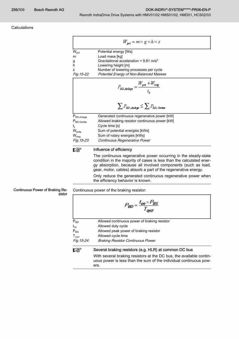
Wpot Potential energy [Ws]m Load mass [kg]g Gravitational acceleration = 9.81 m/s²h Lowering height [m]z Number of lowering processes per cycleFig.15-22: Potential Energy of Non-Balanced Masses
PRD,Anlage Generated continuous regenerative power [kW]PBD,Geräte Allowed braking resistor continuous power [kW]tz Cycle time [s]Wpotg Sum of potential energies [kWs]Wrotg Sum of rotary energies [kWs]Fig.15-23: Continuous Regenerative Power
Influence of efficiencyThe continuous regenerative power occurring in the steady-statecondition in the majority of cases is less than the calculated ener‐gy absorption, because all involved components (such as load,gear, motor, cables) absorb a part of the regenerative energy.Only reduce the generated continuous regenerative power whenthe efficiency behavior is known.
Continuous Power of Braking Re‐sistor
Continuous power of the braking resistor:
PBD Allowed continuous power of braking resistorton Allowed duty cyclePBS Allowed peak power of braking resistorTcycl Allowed cycle timeFig.15-24: Braking Resistor Continuous Power
Several braking resistors (e.g. HLR) at common DC busWith several braking resistors at the DC bus, the available contin‐uous power is less than the sum of the individual continuous pow‐ers.
Bosch Rexroth AG DOK-INDRV*-SYSTEM*****-PR06-EN-P Rexroth IndraDrive Drive Systems with HMV01/02 HMS01/02, HMD01, HCS02/03
256/309
Calculations

PBD_1,PBD_2, PBD_n
Data sheet data of the braking resistors
f Balancing factor for PDB (f = 0.8 (guide value); see also technical dataof converter and supply unit)
Fig.15-25: Sum of Braking Resistor Continuous PowersRelative Duty Cycle of Braking Re‐
sistorThe quotient of ton and Tcycl is understood by the duty cycle ED. The maxi‐mum allowed relative duty cycle EDmax is calculated from the nominal data forHLR braking resistors:
EDmax Maximum allowed relative duty cycleton Allowed duty cycleTcycl Allowed cycle timeFig.15-26: Relative Duty Cycle of Braking Resistor
Braking timesWithin the indicated minimum cycle time Tcycl, the braking resistormay be switched on, as a maximum, for the time ton.
15.1.7 Peak Regenerative PowerUsually, peak regenerative power will occur when an E-Stop signal is trig‐gered and all axes brake simultaneously.
Risk of damage due to extended brakingtimes and distances!
NOTICE
Select the supply unit such that the sum of peak regenerative powers of alldrives does not exceed braking resistor peak power of the supply unit.
See the respective motor selection data for the peak regenerative powers.Peak regenerative power can be roughly calculated by the following equa‐tion:
PRS,Anlage Generated peak regenerated power [kW]PBS,Geräte Allowed braking resistor peak power [kW]Mmax Maximum drive torque [Nm]nmax Maximum NC useful speed [min-1]1,25 Constant for motor and controller efficiencyFig.15-27: Peak Regenerative Power
DOK-INDRV*-SYSTEM*****-PR06-EN-P Rexroth IndraDrive Drive Systems with HMV01/02 HMS01/02, HMD01, HCS02/03
Bosch Rexroth AG 257/309
Calculations
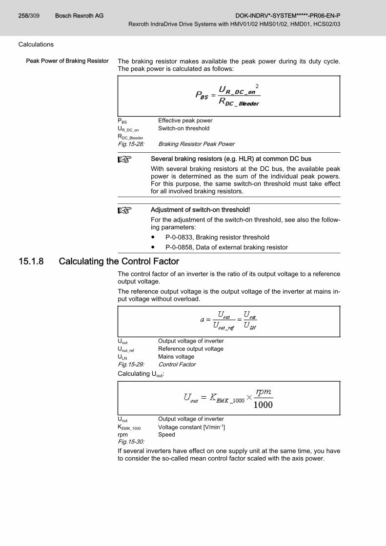
Peak Power of Braking Resistor The braking resistor makes available the peak power during its duty cycle.The peak power is calculated as follows:
PBS Effective peak powerUR_DC_on Switch-on thresholdRDC_BleederFig.15-28: Braking Resistor Peak Power
Several braking resistors (e.g. HLR) at common DC busWith several braking resistors at the DC bus, the available peakpower is determined as the sum of the individual peak powers.For this purpose, the same switch-on threshold must take effectfor all involved braking resistors.
Adjustment of switch-on threshold!For the adjustment of the switch-on threshold, see also the follow‐ing parameters:● P-0-0833, Braking resistor threshold● P-0-0858, Data of external braking resistor
15.1.8 Calculating the Control FactorThe control factor of an inverter is the ratio of its output voltage to a referenceoutput voltage.The reference output voltage is the output voltage of the inverter at mains in‐put voltage without overload.
Uout Output voltage of inverterUout_ref Reference output voltageULN Mains voltageFig.15-29: Control FactorCalculating Uout:
Uout Output voltage of inverterKEMK_1000 Voltage constant [V/min-1]rpm SpeedFig.15-30:If several inverters have effect on one supply unit at the same time, you haveto consider the so-called mean control factor scaled with the axis power.
Bosch Rexroth AG DOK-INDRV*-SYSTEM*****-PR06-EN-P Rexroth IndraDrive Drive Systems with HMV01/02 HMS01/02, HMD01, HCS02/03
258/309
Calculations

n Number of invertersai Several control factorsPZWD DC bus continuous power [kW]Pmi Mechanical continuous power [kW]Fig.15-31: Mean, Scaled Control FactorWhen the control factor falls below the given value (see data PDC_cont in thetechnical data of the corresponding supply unit), additional wattless poweroccurs. The additional wattless power can be compensated with additionalcapacitors in the DC bus. The required additional capacitance can be approx‐imately calculated with the following formula.Applies to a ≤ a0!
CDC_ext Required additional capacitance in DC bus in μFa0 Minimum required control factora Calculated mean control factorPDC_nenn Nominal power of supply unit [kW]ka 200 (preliminary); factor capacitance [μF] / nominal power [kW]Fig.15-32: Required Additional Capacitances When Control Factor Falls Below
Minimum Value
DOK-INDRV*-SYSTEM*****-PR06-EN-P Rexroth IndraDrive Drive Systems with HMV01/02 HMS01/02, HMD01, HCS02/03
Bosch Rexroth AG 259/309
Calculations
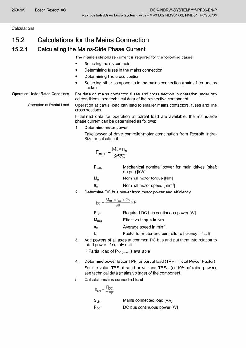
15.2 Calculations for the Mains Connection15.2.1 Calculating the Mains-Side Phase Current
The mains-side phase current is required for the following cases:● Selecting mains contactor● Determining fuses in the mains connection● Determining line cross section● Selecting other components in the mains connection (mains filter, mains
choke)Operation Under Rated Conditions For data on mains contactor, fuses and cross section in operation under rat‐
ed conditions, see technical data of the respective component.Operation at Partial Load Operation at partial load can lead to smaller mains contactors, fuses and line
cross sections.If defined data for operation at partial load are available, the mains-sidephase current can be determined as follows:1. Determine motor power
Take power of drive controller-motor combination from Rexroth Indra‐Size or calculate it.
PmHa Mechanical nominal power for main drives (shaftoutput) [kW]
Mn Nominal motor torque [Nm]nn Nominal motor speed [min-1]
2. Determine DC bus power from motor power and efficiency
PDC Required DC bus continuous power [W]Mrms Effective torque in Nmnm Average speed in min-1
k Factor for motor and controller efficiency = 1.253. Add powers of all axes at common DC bus and put them into relation to
rated power of supply unit⇒ Partial load of PDC_cont is available
4. Determine power factor TPF for partial load (TPF = Total Power Factor)For the value TPF at rated power and TPF10 (at 10% of rated power),see technical data (mains voltage) of the component.
5. Calculate mains connected load
SLN Mains connected load [VA]PDC DC bus continuous power [W]
Bosch Rexroth AG DOK-INDRV*-SYSTEM*****-PR06-EN-P Rexroth IndraDrive Drive Systems with HMV01/02 HMS01/02, HMD01, HCS02/03
260/309
Calculations

TPF Total Power Factor λ6. Calculate mains-side phase current
3-phase:
1-phase: ILN Mains-side phase current in [A]SLN Mains connected load [VA]ULN Voltage between phases of mains [V]
7. Select mains contactor8. Determine mains circuit breaker and line cross section
See chapter 15.3.5 "Dimensioning the Line Cross Sections and Fuses "on page 266
15.2.2 Calculating the Inrush CurrentFor calculating the inrush current, take all devices connected to mains volt‐age into account. The resulting inrush current is the sum of the inrush cur‐rents of the individual devices.
For the data of the inrush current IL_trans_max_on, see Project Planning Man‐ual "Rexroth IndraDrive Supply Units and Power Sections" → Chapter of therespective device → "Technical Data" → "Basic Data" → table "Data for MainsVoltage Supply".
Duration of Inrush Current For components with resistance charge, the inrush current profile is accord‐ing to an exponential function. After the delay td is over, the charging processis completed.Data for calculating the delay td: See chapter 15.4.1 "Charging the DC Bus"on page 276
15.2.3 Calculations for the Mains HarmonicsHarmonic Load THD
The harmonic load of the mains is described by the THD (total harmonic dis‐tortion):
In Harmonic current of the n-th harmonicI1 rms value of the 1st harmonic (fundamental wave)I2 rms value of the 2nd harmonicIn rms value of the n-th harmonicFig.15-33: THD (Total Harmonic Distortion)
Harmonic Content / Distortion Factor kThe harmonic content of, for example, the mains current is described by thedistortion factor k. The distortion factor contains all alternating components,both those of the fundamental wave (I1) and of the harmonics (Ik). Direct com‐ponents (I0) are not contained.
DOK-INDRV*-SYSTEM*****-PR06-EN-P Rexroth IndraDrive Drive Systems with HMV01/02 HMS01/02, HMD01, HCS02/03
Bosch Rexroth AG 261/309
Calculations

ki Distortion factor or harmonic contentIk Harmonic current of the k-th harmonicI1 rms value of the 1st harmonic (fundamental wave)I2 rms value of the 2nd harmonicFig.15-34: Distortion Factor k or Harmonic Content
Power Factor cosφ1 or DPF for Calculating the Wattless Power Load of the MainsThe power factor cosφ1 or DPF (distortion power factor) is used to calculatethe wattless power load of the mains:
Pnetz Effective mains powerS1LN Apparent mains power of fundamental waveFig.15-35: Power Factor cosφ1 / DPF
Power Factor cosφ or TPF (λ)The power factor cosφ or TPF is used for dimensioning mains components(transformer, fuse, etc.):
Pnetz Effective mains powerSLN Apparent mains powerFig.15-36: Power Factor cosφ / TPF/ λ
Only for sinusoidal values does the power factor cosφ equal thetotal power factor TPF (λ).
15.2.4 Mains Voltage UnbalanceThe voltage unbalance is described by a three-phase system consisting ofthe combination of the following systems:● Clockwise AC system (positive-sequence system Um)● Counter-clockwise AC system (negative-sequence system Ug)● DC system (U0)
Bosch Rexroth AG DOK-INDRV*-SYSTEM*****-PR06-EN-P Rexroth IndraDrive Drive Systems with HMV01/02 HMS01/02, HMD01, HCS02/03
262/309
Calculations
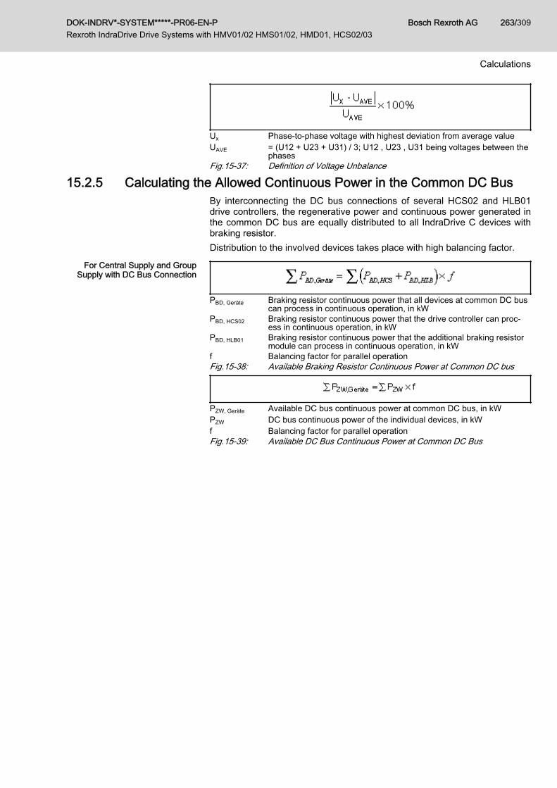
Ux Phase-to-phase voltage with highest deviation from average valueUAVE = (U12 + U23 + U31) / 3; U12 , U23 , U31 being voltages between the
phasesFig.15-37: Definition of Voltage Unbalance
15.2.5 Calculating the Allowed Continuous Power in the Common DC BusBy interconnecting the DC bus connections of several HCS02 and HLB01drive controllers, the regenerative power and continuous power generated inthe common DC bus are equally distributed to all IndraDrive C devices withbraking resistor.Distribution to the involved devices takes place with high balancing factor.
For Central Supply and GroupSupply with DC Bus Connection
PBD, Geräte Braking resistor continuous power that all devices at common DC buscan process in continuous operation, in kW
PBD, HCS02 Braking resistor continuous power that the drive controller can proc‐ess in continuous operation, in kW
PBD, HLB01 Braking resistor continuous power that the additional braking resistormodule can process in continuous operation, in kW
f Balancing factor for parallel operationFig.15-38: Available Braking Resistor Continuous Power at Common DC bus
PZW, Geräte Available DC bus continuous power at common DC bus, in kWPZW DC bus continuous power of the individual devices, in kWf Balancing factor for parallel operationFig.15-39: Available DC Bus Continuous Power at Common DC Bus
DOK-INDRV*-SYSTEM*****-PR06-EN-P Rexroth IndraDrive Drive Systems with HMV01/02 HMS01/02, HMD01, HCS02/03
Bosch Rexroth AG 263/309
Calculations

15.3 Determining Components in the Mains Connection15.3.1 Determining the Mains Choke
When using mains chokes, take their effect on the connected drive control‐lers into account. Due to their inductance, mains chokes have a smoothingeffect on the current and thereby reduce harmonics.Take the nominal current of the mains choke into account to have the induc‐tance of the mains choke available.Some mains chokes are assigned to certain drive controllers (see technicaldata of the drive controller "Data for mains voltage supply → Assigned type ofmains choke").
15.3.2 Determining the Mains FilterCriteria for Selecting the Mains Fil‐
terTake the following criteria into account for selecting the appropriate mains fil‐ter:● EMC limit value class on site● Ambient conditions on site● Harmonics on mains voltage on site● Loading by mains voltage and mains frequency on site● Loading by harmonics on site● Loading by mains-side phase current● Total length of connected power cables● Sum of leakage capacitances● Clock frequency of drive controller
How to Proceed for Selecting theMains Filter
The selection of the mains filter is significantly determined by the operatingconditions. How to proceed for selecting the mains filter:1. Determine the required EMC limit value class for the application.2. Determine the maximum applied mains voltage.
Observe that not all Rexroth IndraDrive mains filters are suited for amains voltage of 3 AC 500 V.Check whether the mains voltage of the mains filter is loaded with har‐monics and still allowed for the mains filter.Allowed operating data depending on existing harmonics: See chapter18.3 "Emitted Harmonics on Mains Current and Mains Voltage" onpage 290If necessary, reduce the harmonics on site.
3. Determine the kind of mains connection, such as central supply, groupsupply etc. (to do this, it is useful to outline the involved componentsand their interaction).
4. Calculate the mains-side phase current of the mains filter.Procedure for calculating the mains-side phase current: See chapter15.2.1 "Calculating the Mains-Side Phase Current " on page 260For selecting the components, calculate the effective rms value.Check or determine the maximum occurring ambient temperature. Se‐lect a mains filter with higher nominal current, when the ambient temper‐ature is above 45 °C.
5. Select a mains contactor the nominal current of which does not exceednominal current of the mains filter.
Bosch Rexroth AG DOK-INDRV*-SYSTEM*****-PR06-EN-P Rexroth IndraDrive Drive Systems with HMV01/02 HMS01/02, HMD01, HCS02/03
264/309
Calculations

6. Determine the number of drive axes.An HMD drive controller, for example, counts as two drive axes.
7. Determine the total length of the connected power cables.8. Determine the sum of the leakage capacitances on the load side of the
mains filter. The sum of the leakage capacitances results from the num‐ber of operated axes and the length of the connected power cables.Procedure for determining the leakage capacitance: See chapter 15.3.6 "Determining the Leakage Capacitance" on page 272
9. Select the appropriate mains connection (supply unit/converter, mainschoke, mains filter) from the corresponding tables in chapter 8.3 "MainsConnection Supply Units and Converters" on page 106.
The capacity of the mains filters regarding the maximum allowed number ofdrive controllers and the maximum allowed total power cable length dependson whether you use an HMV supply unit or supply other drive controllers withHCS drive controllers. For supply by an HMV supply unit, the allowed numberand allowed total length are higher.
Notes on Installation When using HNF01, NFD03, HNS02 or HNK01 mains filters atmains grounded via outer conductor, install an isolating trans‐former between mains and mains filter.
15.3.3 Determining Mains Transformer DLT
When using HNF01, NFD03, HNS02 or HNK01 mains filters atmains grounded via outer conductor, install an isolating trans‐former between mains and mains filter.
How to Proceed for Selecting theMains Transformer
The selection of the mains transformer is significantly determined by the con‐ditions at the connection point and the supply unit used.
Procedure1. Determine Sk_min (minimum short circuit power of the mains for failure-
free operation) of the supply unit used.See Project Planning Manual "Rexroth IndraDrive Supply Units andPower Sections", "Data for Mains Voltage Supply"
2. In the table "Mains Classified According to Mains Short Circuit Powerand Mains Internal Resistance", read the inductance Lk_min of the mainsphase in row of Sk_min.
3. Determine the short circuit power Sk present at the connection point.4. In the table "Mains Classified According to Mains Short Circuit Power
and Mains Internal Resistance", read the inductance of the mains phasein row of Sk.
5. Calculate difference L: Lk_min - Lk
6. Calculate apparent power STrafo:STrafo = (U2
LN × uk) / (L × 6.28 × fLN)Relative short-circuit voltage uk of DLT transformers is approx. 4%.
15.3.4 Mains Contactor and Fusing To protect the supply mains and the components in the supply feeder (lines,mains contactor, mains filter, mains choke, converter, supply unit, etc.) for thecase of a short circuit, install fuses in the supply feeder.
DOK-INDRV*-SYSTEM*****-PR06-EN-P Rexroth IndraDrive Drive Systems with HMV01/02 HMS01/02, HMD01, HCS02/03
Bosch Rexroth AG 265/309
Calculations

Operation Under Rated Conditions In operation under rated conditions, the component is operated in individualsupply with the rated power PDC_cont.
For the data of mains contactor, fusing and the required connection crosssection in operation under rated conditions, see Project Planning Manual"Rexroth IndraDrive Supply Units and Power Sections" → Chapter of the re‐spective device → "Technical Data" → "Basic Data" → table "Data for MainsVoltage Supply".
Operation at Partial Load If several drive controllers are to be operated at partial load (power smallerthan rated power) at one mains circuit breaker and one mains contactor only,add the mains-side phase currents and inrush currents calculated for the indi‐vidual drives and therefor determine the mains circuit breaker.
Dimensioning the fuse for operation at partial loadThe nominal current of the selected fuse before the drive systemmustn't be greater than the mains circuit breaker of the smallestconverter or supply unit.Use more powerful converters or supply units in the drive system.For dimensioning line cross sections and fuses, see also chapter15.3.5 "Dimensioning the Line Cross Sections and Fuses " onpage 266.
Fusing Branches within the Con‐trol Cabinet
In the wiring of the drive system devices, there are branches run from mainlines to short circuit protection devices.In accordance with EN 60204-1:2005, 7.2.8, such supply lines to short circuitprotection devices branching off main lines do not need to be especially pro‐tected against short circuit, when the following requirements have been fulfil‐led:● The supply lines to the short circuit protection device have at least the
cross section of the conductors continuing the line from the short circuitprotection device (line cross sections from and to motor circuit breakerhave the same size).
● No supply line to the short circuit protection device is longer than 3 m.● The lines are protected against external influence by a housing or a wir‐
ing duct.● The lines are not run close to combustible material.
15.3.5 Dimensioning the Line Cross Sections and Fuses Dimensioning the line cross sections and fuses in the supply feederand branches to the drive system:
1. Determine current in supply feeder of drive system and correct it withcorrection factors for ambient temperature and bundling.(In the technical data of the components in section "Data for Mains Volt‐age Supply", you can find standardized data for connection cross sec‐tion and mains circuit breaker at operation under rated conditions.)
2. Determine country of use ("international except for USA/Canada" or"USA/Canada")
3. Determine installation type (e.g. B1 or B2)4. In table row "Current I", select value immediately above the value deter‐
mined in the first step5. In table row "Nominal current fuse", read corresponding fuse
Bosch Rexroth AG DOK-INDRV*-SYSTEM*****-PR06-EN-P Rexroth IndraDrive Drive Systems with HMV01/02 HMS01/02, HMD01, HCS02/03
266/309
Calculations

6. In table row "Cross section A …", read corresponding required crosssection
Country of use: International except for USA/Canada
Current I Nominal current fuse Cross section Afor installation type B1
A A mm2
1,6 2 1,5Minimum cross section acc. to
EN 60204‑1:2006, table 5(Main circuits; outside of hous‐ings; permanently installed; sin‐gle-core lines; stranded wire de‐
sign class 2)
3,3 4
5,0 6
8,6 10
10,3 16
13,5 16
18,3 20 2,5
22 25 4
28 32 6
31 40 6
35 40 10
44 50 10
59 63 16
77 80 25
96 100 35
117 125 50
149 160 70
180 200 95
208 250 120
227 250 150
257 315 185
301 355 240
342 400 300
Tab.15-2: Line Cross Sections and Fuses, B1 According to EN 60204-1:2006,Table 6, as of 150mm² DIN IEC 60364-5-52:2004, Table B.52-4
DOK-INDRV*-SYSTEM*****-PR06-EN-P Rexroth IndraDrive Drive Systems with HMV01/02 HMS01/02, HMD01, HCS02/03
Bosch Rexroth AG 267/309
Calculations
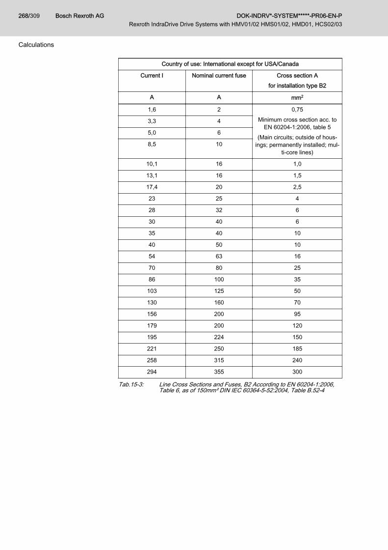
Country of use: International except for USA/Canada
Current I Nominal current fuse Cross section Afor installation type B2
A A mm2
1,6 2 0,75Minimum cross section acc. to
EN 60204‑1:2006, table 5(Main circuits; outside of hous‐
ings; permanently installed; mul‐ti-core lines)
3,3 4
5,0 6
8,5 10
10,1 16 1,0
13,1 16 1,5
17,4 20 2,5
23 25 4
28 32 6
30 40 6
35 40 10
40 50 10
54 63 16
70 80 25
86 100 35
103 125 50
130 160 70
156 200 95
179 200 120
195 224 150
221 250 185
258 315 240
294 355 300
Tab.15-3: Line Cross Sections and Fuses, B2 According to EN 60204-1:2006,Table 6, as of 150mm² DIN IEC 60364-5-52:2004, Table B.52-4
Bosch Rexroth AG DOK-INDRV*-SYSTEM*****-PR06-EN-P Rexroth IndraDrive Drive Systems with HMV01/02 HMS01/02, HMD01, HCS02/03
268/309
Calculations
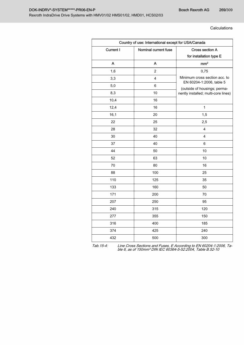
Country of use: International except for USA/Canada
Current I Nominal current fuse Cross section Afor installation type E
A A mm2
1,6 2 0,75Minimum cross section acc. to
EN 60204‑1:2006, table 5(outside of housings; perma‐
nently installed; multi-core lines)
3,3 4
5,0 6
8,3 10
10,4 16
12,4 16 1
16,1 20 1,5
22 25 2,5
28 32 4
30 40 4
37 40 6
44 50 10
52 63 10
70 80 16
88 100 25
110 125 35
133 160 50
171 200 70
207 250 95
240 315 120
277 355 150
316 400 185
374 425 240
432 500 300
Tab.15-4: Line Cross Sections and Fuses, E According to EN 60204-1:2006, Ta‐ble 6, as of 150mm² DIN IEC 60364-5-52:2004, Table B.52-10
DOK-INDRV*-SYSTEM*****-PR06-EN-P Rexroth IndraDrive Drive Systems with HMV01/02 HMS01/02, HMD01, HCS02/03
Bosch Rexroth AG 269/309
Calculations

Country of use: USA/Canada
Current I Nominal current fuse Cross section A
A A AWG
1,6 2 14Minimum cross section acc. toUL 508 A:2007, chapter 29.6
3,3 4 14
5,0 6 14
8,3 10 14
13 15 14
15 20 14
20 25 12
30 40 10
50 70 8
65 80 6
85 100 4
100 110 3
115 125 2
130 150 1
150 175 1/0
175 200 2/0
200 225 3/0
230 250 4/0
255 300 250 kcmil
285 300 300 kcmil
310 350 350 kcmil
335 350 400 kcmil
380 400 500 kcmil
420 450 600 kcmil
Tab.15-5: Line Cross Sections and Fuses According to UL508A:2007, Table28.1
Dimensioning variables of the table values1. Ambient temperature TA of routed lines ≤ 40 °C2. Temperature TL at conductor at nominal current: 90 °C for UL-listed
lines (USA/Canada) or 70 °C for PVC lines3. The nominal current of the fuse is approx. 10-20% above the nominal
current ILN of the converter/supply unit or the determined current of thedrive system.
4. Installation types:
Bosch Rexroth AG DOK-INDRV*-SYSTEM*****-PR06-EN-P Rexroth IndraDrive Drive Systems with HMV01/02 HMS01/02, HMD01, HCS02/03
270/309
Calculations
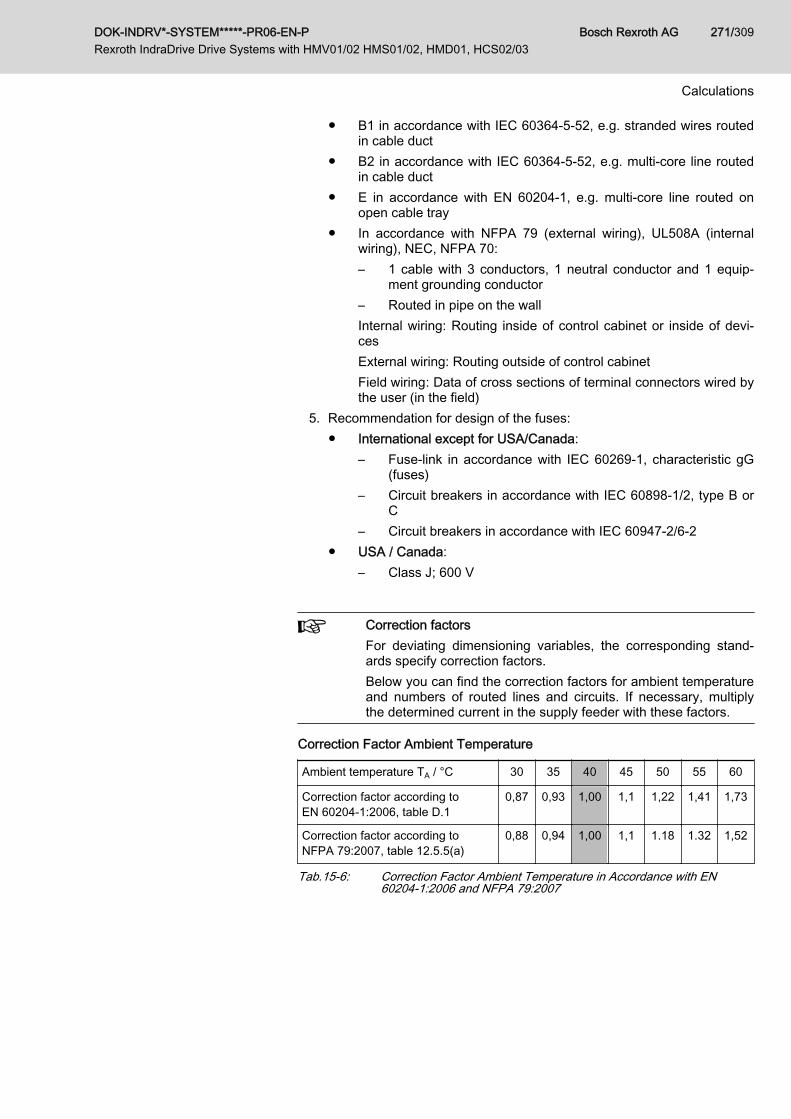
● B1 in accordance with IEC 60364-5-52, e.g. stranded wires routedin cable duct
● B2 in accordance with IEC 60364-5-52, e.g. multi-core line routedin cable duct
● E in accordance with EN 60204-1, e.g. multi-core line routed onopen cable tray
● In accordance with NFPA 79 (external wiring), UL508A (internalwiring), NEC, NFPA 70:– 1 cable with 3 conductors, 1 neutral conductor and 1 equip‐
ment grounding conductor– Routed in pipe on the wallInternal wiring: Routing inside of control cabinet or inside of devi‐cesExternal wiring: Routing outside of control cabinetField wiring: Data of cross sections of terminal connectors wired bythe user (in the field)
5. Recommendation for design of the fuses: ● International except for USA/Canada:
– Fuse-link in accordance with IEC 60269-1, characteristic gG(fuses)
– Circuit breakers in accordance with IEC 60898-1/2, type B orC
– Circuit breakers in accordance with IEC 60947-2/6-2● USA / Canada:
– Class J; 600 V
Correction factorsFor deviating dimensioning variables, the corresponding stand‐ards specify correction factors.Below you can find the correction factors for ambient temperatureand numbers of routed lines and circuits. If necessary, multiplythe determined current in the supply feeder with these factors.
Correction Factor Ambient Temperature
Ambient temperature TA / °C 30 35 40 45 50 55 60
Correction factor according toEN 60204‑1:2006, table D.1
0,87 0,93 1,00 1,1 1,22 1,41 1,73
Correction factor according toNFPA 79:2007, table 12.5.5(a)
0,88 0,94 1,00 1,1 1.18 1.32 1,52
Tab.15-6: Correction Factor Ambient Temperature in Accordance with EN60204-1:2006 and NFPA 79:2007
DOK-INDRV*-SYSTEM*****-PR06-EN-P Rexroth IndraDrive Drive Systems with HMV01/02 HMS01/02, HMD01, HCS02/03
Bosch Rexroth AG 271/309
Calculations
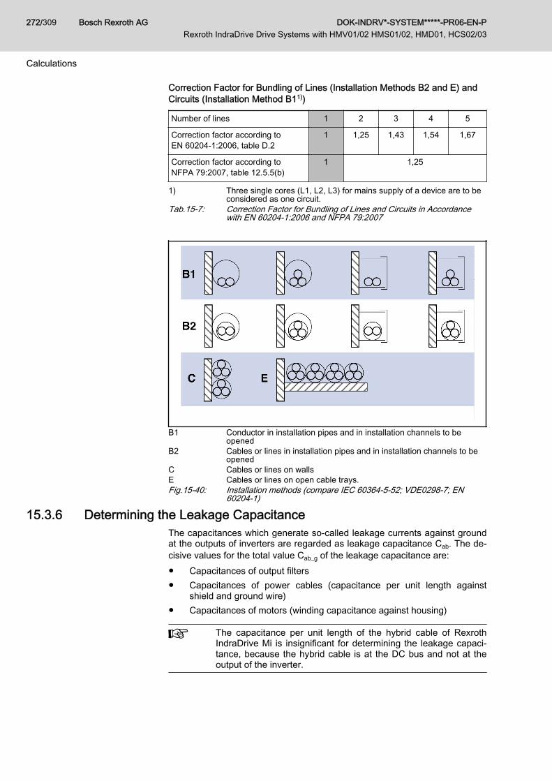
Correction Factor for Bundling of Lines (Installation Methods B2 and E) andCircuits (Installation Method B11))
Number of lines 1 2 3 4 5
Correction factor according toEN 60204‑1:2006, table D.2
1 1,25 1,43 1,54 1,67
Correction factor according toNFPA 79:2007, table 12.5.5(b)
1 1,25
1) Three single cores (L1, L2, L3) for mains supply of a device are to beconsidered as one circuit.
Tab.15-7: Correction Factor for Bundling of Lines and Circuits in Accordancewith EN 60204-1:2006 and NFPA 79:2007
B1 Conductor in installation pipes and in installation channels to beopened
B2 Cables or lines in installation pipes and in installation channels to beopened
C Cables or lines on wallsE Cables or lines on open cable trays.Fig.15-40: Installation methods (compare IEC 60364-5-52; VDE0298-7; EN
60204-1)
15.3.6 Determining the Leakage CapacitanceThe capacitances which generate so-called leakage currents against groundat the outputs of inverters are regarded as leakage capacitance Cab. The de‐cisive values for the total value Cab_g of the leakage capacitance are:● Capacitances of output filters● Capacitances of power cables (capacitance per unit length against
shield and ground wire)● Capacitances of motors (winding capacitance against housing)
The capacitance per unit length of the hybrid cable of RexrothIndraDrive Mi is insignificant for determining the leakage capaci‐tance, because the hybrid cable is at the DC bus and not at theoutput of the inverter.
Bosch Rexroth AG DOK-INDRV*-SYSTEM*****-PR06-EN-P Rexroth IndraDrive Drive Systems with HMV01/02 HMS01/02, HMD01, HCS02/03
272/309
Calculations
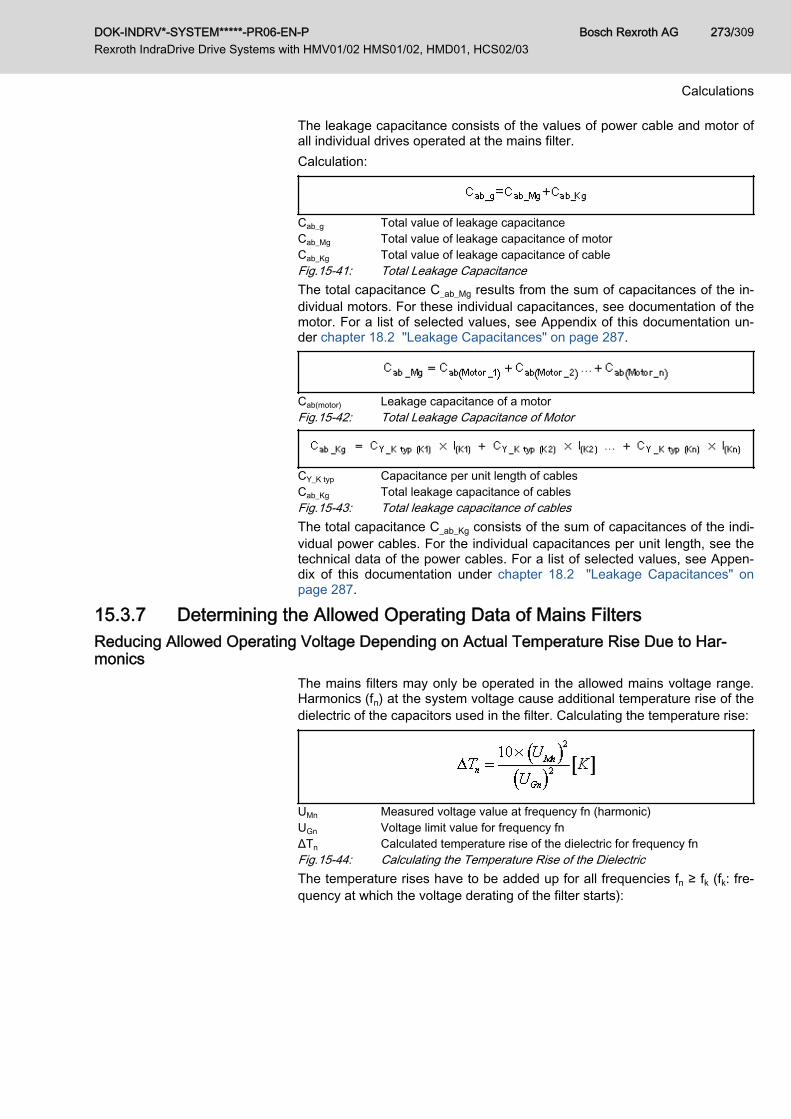
The leakage capacitance consists of the values of power cable and motor ofall individual drives operated at the mains filter.Calculation:
Cab_g Total value of leakage capacitanceCab_Mg Total value of leakage capacitance of motorCab_Kg Total value of leakage capacitance of cableFig.15-41: Total Leakage CapacitanceThe total capacitance C_ab_Mg results from the sum of capacitances of the in‐dividual motors. For these individual capacitances, see documentation of themotor. For a list of selected values, see Appendix of this documentation un‐der chapter 18.2 "Leakage Capacitances" on page 287.
Cab(motor) Leakage capacitance of a motorFig.15-42: Total Leakage Capacitance of Motor
CY_K typ Capacitance per unit length of cablesCab_Kg Total leakage capacitance of cablesFig.15-43: Total leakage capacitance of cablesThe total capacitance C_ab_Kg consists of the sum of capacitances of the indi‐vidual power cables. For the individual capacitances per unit length, see thetechnical data of the power cables. For a list of selected values, see Appen‐dix of this documentation under chapter 18.2 "Leakage Capacitances" onpage 287.
15.3.7 Determining the Allowed Operating Data of Mains FiltersReducing Allowed Operating Voltage Depending on Actual Temperature Rise Due to Har‐monics
The mains filters may only be operated in the allowed mains voltage range.Harmonics (fn) at the system voltage cause additional temperature rise of thedielectric of the capacitors used in the filter. Calculating the temperature rise:
UMn Measured voltage value at frequency fn (harmonic)UGn Voltage limit value for frequency fnΔTn Calculated temperature rise of the dielectric for frequency fnFig.15-44: Calculating the Temperature Rise of the DielectricThe temperature rises have to be added up for all frequencies fn ≥ fk (fk: fre‐quency at which the voltage derating of the filter starts):
DOK-INDRV*-SYSTEM*****-PR06-EN-P Rexroth IndraDrive Drive Systems with HMV01/02 HMS01/02, HMD01, HCS02/03
Bosch Rexroth AG 273/309
Calculations
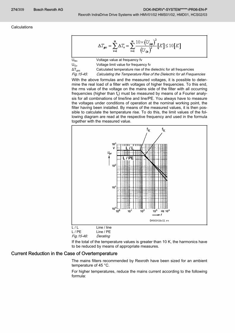
UMv Voltage value at frequency fvUGv Voltage limit value for frequency fvΔTges Calculated temperature rise of the dielectric for all frequenciesFig.15-45: Calculating the Temperature Rise of the Dielectric for all FrequenciesWith the above formulas and the measured voltages, it is possible to deter‐mine the real load of a filter with voltages of higher frequencies. To this end,the rms value of the voltage on the mains side of the filter with all occurringfrequencies (higher than fk) must be measured by means of a Fourier analy‐sis for all combinations of line/line and line/PE. You always have to measurethe voltages under conditions of operation at the nominal working point, thefilter having been installed. By means of the measured values, it is then pos‐sible to calculate the temperature rise. To do this, the limit values of the fol‐lowing diagram are read at the respective frequency and used in the formulatogether with the measured value.
L / L Line / lineL / PE Line / PEFig.15-46: DeratingIf the total of the temperature values is greater than 10 K, the harmonics haveto be reduced by means of appropriate measures.
Current Reduction in the Case of OvertemperatureThe mains filters recommended by Rexroth have been sized for an ambienttemperature of 45 °C.For higher temperatures, reduce the mains current according to the followingformula:
Bosch Rexroth AG DOK-INDRV*-SYSTEM*****-PR06-EN-P Rexroth IndraDrive Drive Systems with HMV01/02 HMS01/02, HMD01, HCS02/03
274/309
Calculations

INetz Nominal current of filter at 45 °CTamb Ambient temperature on siteFig.15-47: Current Reduction in the Case of Overtemperature
DOK-INDRV*-SYSTEM*****-PR06-EN-P Rexroth IndraDrive Drive Systems with HMV01/02 HMS01/02, HMD01, HCS02/03
Bosch Rexroth AG 275/309
Calculations
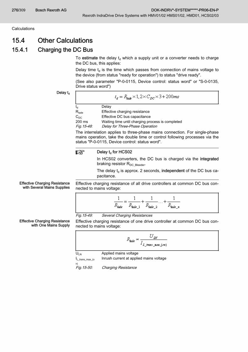
15.4 Other Calculations15.4.1 Charging the DC Bus
To estimate the delay td which a supply unit or a converter needs to chargethe DC bus, this applies:Delay time td is the time which passes from connection of mains voltage tothe device (from status "ready for operation") to status "drive ready".(See also parameter "P-0-0115, Device control: status word" or "S-0-0135,Drive status word")
Delay td
td DelayRlade Effective charging resistanceCDC Effective DC bus capacitance200 ms Waiting time until charging process is completedFig.15-48: Delay for Three-Phase OperationThe interrelation applies to three-phase mains connection. For single-phasemains operation, take the double time or control following processes via thestatus "P-0-0115, Device control: status word".
Delay td for HCS02In HCS02 converters, the DC bus is charged via the integratedbraking resistor RDC_Bleeder. The delay td is approx. 2 seconds, independent of the DC bus ca‐pacitance.
Effective Charging Resistancewith Several Mains Supplies
Effective charging resistance of all drive controllers at common DC bus con‐nected to mains voltage:
Fig.15-49: Several Charging ResistancesEffective Charging Resistance
with One Mains SupplyEffective charging resistance of one drive controller at common DC bus con‐nected to mains voltage:
ULN Applied mains voltageIL_trans_max_(on)
Inrush current at applied mains voltage
Fig.15-50: Charging Resistance
Bosch Rexroth AG DOK-INDRV*-SYSTEM*****-PR06-EN-P Rexroth IndraDrive Drive Systems with HMV01/02 HMS01/02, HMD01, HCS02/03
276/309
Calculations

Charging resistance of HCS03 convertersIn HCS03.1E-W0070…0150 converters, the DC bus is chargedvia integrated resistors for charging current limitation, and inHCS03.1E-W0210 converters, it is charged via a thyristor circuit:
The charging ability is limited by the properties of the integratedresistor; its resistance value clearly rises with increasing thermalload.
For the data of the inrush current IL_trans_max_on and the mains voltage ULN,see Project Planning Manual "Rexroth IndraDrive Supply Units and PowerSections" → Chapter of the respective device → "Technical Data" → "BasicData" → table "Data for Mains Voltage Supply".
Resulting DC Bus Capacitance Effective DC bus capacitance of all devices at common DC bus:
CDC Capacitance in DC busFig.15-51: DC Bus Capacitance
For the data of the capacitance in DC bus CDC, see Project PlanningManual "Rexroth IndraDrive Supply Units and Power Sections" → Chapter ofthe respective device → "Technical Data" → "Basic Data" → table "Data ofPower Section - DC bus".
15.4.2 Calculating Speed Characteristic and Braking Time With DC BusShort Circuit (ZKS)
Components equipped with the ZKS function (e.g HLB01) short-circuit the DCbus via the braking resistor when the DC bus short circuit (ZKS) is active. Atsynchronous motors with permanent magnet excitation, the short circuit cau‐ses speed-dependent braking torque.The braking torque and the braking time can be estimated with the followingformulas.
The calculation formulas below can only be applied to rotary mo‐tors for which, in addition, the relation Ld / Lq must be approx. 1.
Basic Formula 1
ω0 [Initial angular velocity motor] = s-1
n0 [Motor speed at beginning of ZKS] = min-1
Fig.15-52: Initial Angular Velocity
DOK-INDRV*-SYSTEM*****-PR06-EN-P Rexroth IndraDrive Drive Systems with HMV01/02 HMS01/02, HMD01, HCS02/03
Bosch Rexroth AG 277/309
Calculations

Basic Formula 2
R´ [Transformed resistance] = ΩRS [Winding resistance motor] = Ω; see P-0-4048 *0.5RDC_Bleeder [Effective braking resistance with ZKS] = ΩFig.15-53: Transformed ResistanceOccurring Torque
Mmax Maximum occurring torque (friction not taken into account)KM [Torque constant motor] = Nm/A; see P-0-0051L [Winding inductance motor] = H; see P-0-4016zp Number of pole pairs motor; see P-0-0018Fig.15-54: Occurring TorqueBraking Torque vs. Angular Velocity
KM [Torque constant motor] = Nm/A; see P-0-0051ω [Angular velocity motor] = s-1
R´ [Transformed resistance] = ΩL [Winding inductance motor] = H; see P-0-4016zp Number of pole pairs motor; see P-0-0018Fig.15-55: Braking Torque Depending on Angular VelocityBraking Torque vs. Speed
KM [Torque constant motor] = Nm/A; see P-0-0051n [Motor speed] = min-1
R´ [Transformed resistance] = ΩL [Winding inductance motor] = H; see P-0-4016zp Number of pole pairs motor; see P-0-0018Fig.15-56: Braking Torque Depending on Motor Speed
Bosch Rexroth AG DOK-INDRV*-SYSTEM*****-PR06-EN-P Rexroth IndraDrive Drive Systems with HMV01/02 HMS01/02, HMD01, HCS02/03
278/309
Calculations
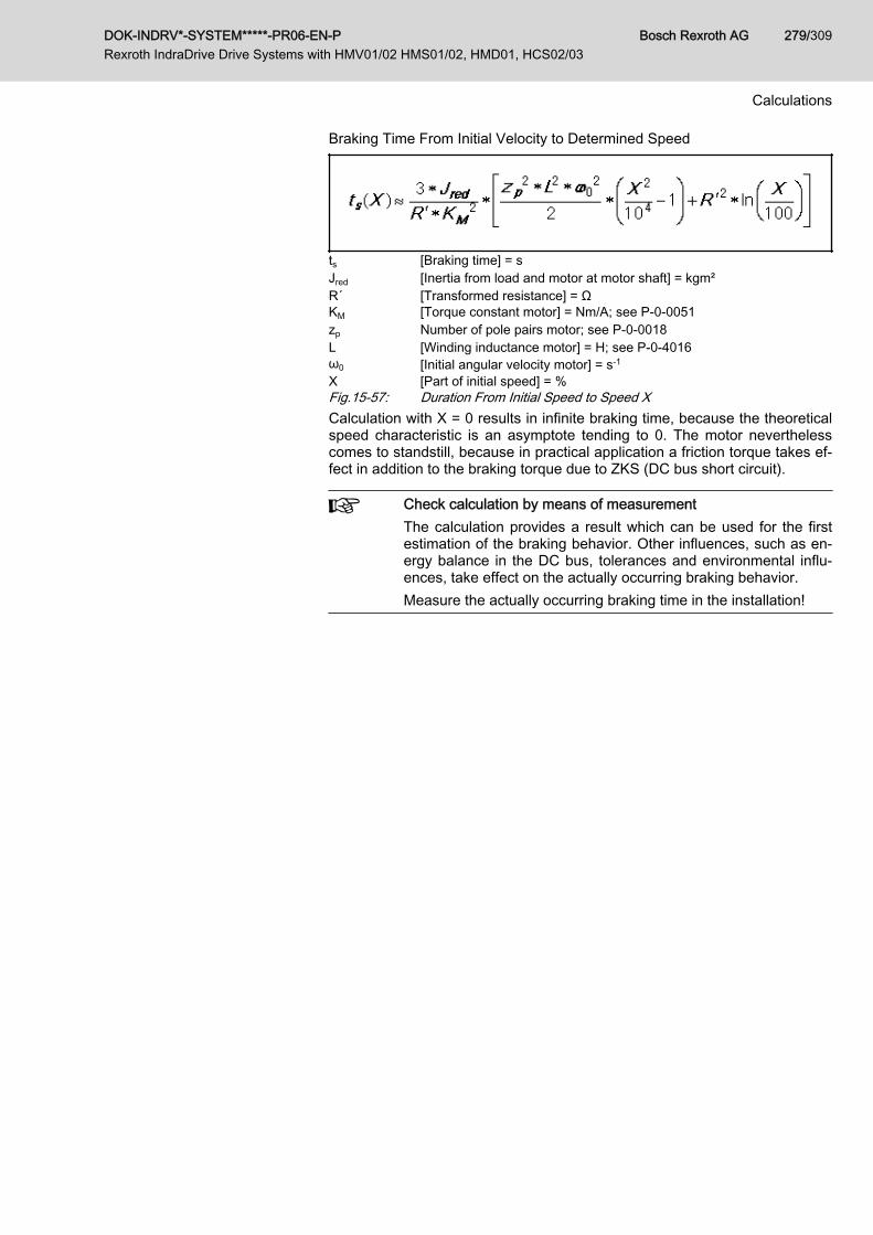
Braking Time From Initial Velocity to Determined Speed
ts [Braking time] = sJred [Inertia from load and motor at motor shaft] = kgm²R´ [Transformed resistance] = ΩKM [Torque constant motor] = Nm/A; see P-0-0051zp Number of pole pairs motor; see P-0-0018L [Winding inductance motor] = H; see P-0-4016ω0 [Initial angular velocity motor] = s-1
X [Part of initial speed] = %Fig.15-57: Duration From Initial Speed to Speed XCalculation with X = 0 results in infinite braking time, because the theoreticalspeed characteristic is an asymptote tending to 0. The motor neverthelesscomes to standstill, because in practical application a friction torque takes ef‐fect in addition to the braking torque due to ZKS (DC bus short circuit).
Check calculation by means of measurementThe calculation provides a result which can be used for the firstestimation of the braking behavior. Other influences, such as en‐ergy balance in the DC bus, tolerances and environmental influ‐ences, take effect on the actually occurring braking behavior.Measure the actually occurring braking time in the installation!
DOK-INDRV*-SYSTEM*****-PR06-EN-P Rexroth IndraDrive Drive Systems with HMV01/02 HMS01/02, HMD01, HCS02/03
Bosch Rexroth AG 279/309
Calculations

Bosch Rexroth AG DOK-INDRV*-SYSTEM*****-PR06-EN-P Rexroth IndraDrive Drive Systems with HMV01/02 HMS01/02, HMD01, HCS02/03
280/309
16 Environmental Protection and Disposal16.1 Environmental Protection
Production Processes The products are made with energy- and resource-optimized production pro‐cesses which allow re-using and recycling the resulting waste. We regularlytry to replace pollutant-loaded raw materials and supplies by more environ‐ment-friendly alternatives.
No Release of Hazardous Sub‐stances
Our products do not contain any hazardous substances which may be re‐leased in the case of appropriate use. Normally, our products will not haveany negativ influences on the environment.
Significant Components Basically, our products contain the following components:Electronic devices Motors∙ steel ∙ steel∙ aluminum ∙ aluminum∙ copper ∙ copper∙ synthetic materials ∙ brass∙ electronic components and modules ∙ magnetic materials ∙ electronic components and modules
16.2 DisposalReturn of Products Our products can be returned to our premises free of charge for disposal. It is
a precondition, however, that the products are free of oil, grease or other dirt.Furthermore, the products returned for disposal must not contain any undueforeign material or foreign components.Send the products ”free domicile” to the following address: Bosch Rexroth AG Electric Drives and Controls Buergermeister-Dr.-Nebel-Strasse 2 97816 Lohr am Main, Germany
Packaging The packaging materials consist of cardboard, wood and polystyrene. Thesematerials can be recycled anywhere without any problem.For ecological reasons, please refrain from returning the empty packages tous.
Batteries and Accumulators Batteries and accumulators can be labeled with this symbol.
The symbol indicating "separate collection" for all batteries and accu‐mulators is the crossed-out wheeled bin.The end user within the EU is legally obligated to return used batteries. Out‐side the validity of the EU Directive 2006/66/EC keep the stipulated direc‐tives.Used batteries can contain hazardous substances, which can harm the envi‐ronment or the people´s health when they are improper stored or disposed of.After use, the batteries or accumulators contained in Rexroth products haveto be properly disposed of according to the country-specific collection.
Recycling Most of the products can be recycled due to their high content of metal. Inorder to recycle the metal in the best possible way, the products must be dis‐assembled into individual modules.
DOK-INDRV*-SYSTEM*****-PR06-EN-P Rexroth IndraDrive Drive Systems with HMV01/02 HMS01/02, HMD01, HCS02/03
Bosch Rexroth AG 281/309
Environmental Protection and Disposal

Metals contained in electric and electronic modules can also be recycled bymeans of special separation processes.Products made of plastics can contain flame retardants. These plastic partsare labeled according to EN ISO 1043. They have to be recycled separatelyor disposed of according to the valid legal requirements.
Bosch Rexroth AG DOK-INDRV*-SYSTEM*****-PR06-EN-P Rexroth IndraDrive Drive Systems with HMV01/02 HMS01/02, HMD01, HCS02/03
282/309
Environmental Protection and Disposal

17 Service and SupportOur worldwide service network provides an optimized and efficient support.Our experts offer you advice and assistance should you have any queries.You can contact us 24/7.
Service Germany Our technology-oriented Competence Center in Lohr, Germany, is responsi‐ble for all your service-related queries for electric drive and controls.Contact the Service Helpdesk & Hotline under:
Phone: +49 9352 40 5060Fax: +49 9352 18 4941E-mail: [email protected]: http://www.boschrexroth.com
Additional information on service, repair (e.g. delivery addresses) and trainingcan be found on our internet sites.
Service worldwide Outside Germany, please contact your local service office first. For hotlinenumbers, refer to the sales office addresses on the internet.
Preparing information To be able to help you more quickly and efficiently, please have the followinginformation ready:● Detailed description of malfunction and circumstances resulting in the
malfunction● Type plate name of the affected products, in particular type codes and
serial numbers● Your contact data (phone and fax number as well as your email ad‐
dress)
DOK-INDRV*-SYSTEM*****-PR06-EN-P Rexroth IndraDrive Drive Systems with HMV01/02 HMS01/02, HMD01, HCS02/03
Bosch Rexroth AG 283/309
Service and Support

Bosch Rexroth AG DOK-INDRV*-SYSTEM*****-PR06-EN-P Rexroth IndraDrive Drive Systems with HMV01/02 HMS01/02, HMD01, HCS02/03
284/309
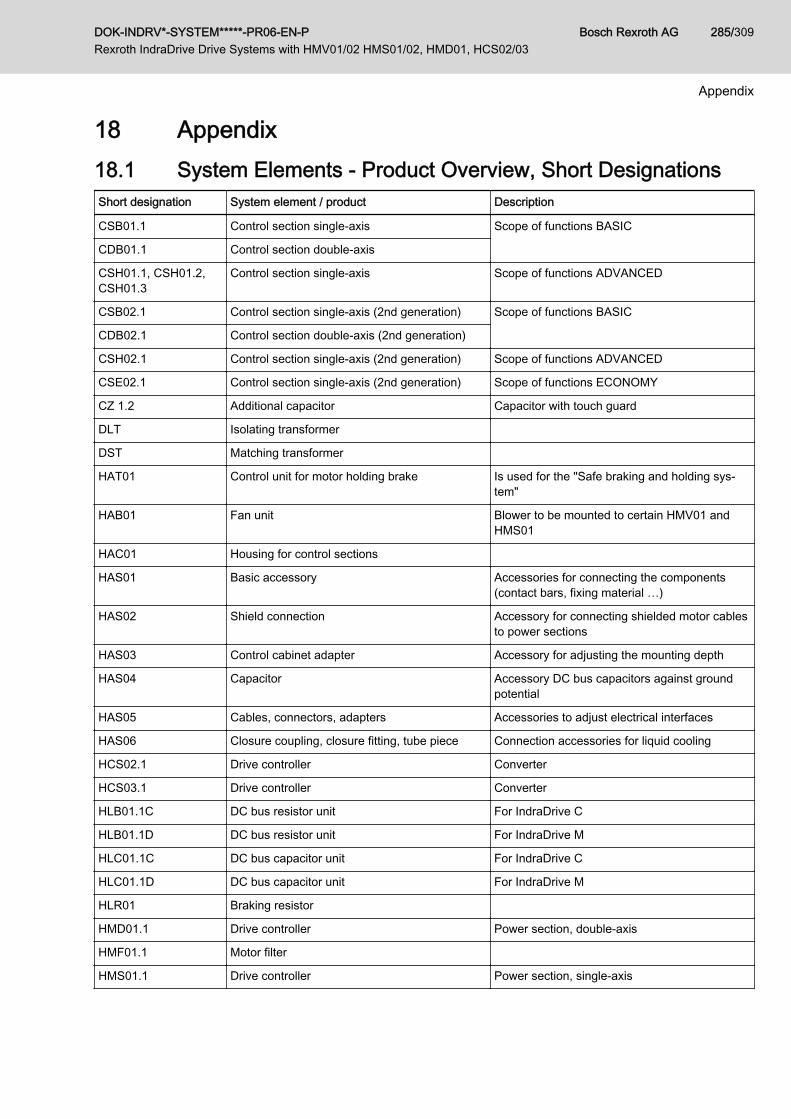
18 Appendix18.1 System Elements - Product Overview, Short DesignationsShort designation System element / product Description
CSB01.1 Control section single-axis Scope of functions BASIC
CDB01.1 Control section double-axis
CSH01.1, CSH01.2,CSH01.3
Control section single-axis Scope of functions ADVANCED
CSB02.1 Control section single-axis (2nd generation) Scope of functions BASIC
CDB02.1 Control section double-axis (2nd generation)
CSH02.1 Control section single-axis (2nd generation) Scope of functions ADVANCED
CSE02.1 Control section single-axis (2nd generation) Scope of functions ECONOMY
CZ 1.2 Additional capacitor Capacitor with touch guard
DLT Isolating transformer
DST Matching transformer
HAT01 Control unit for motor holding brake Is used for the "Safe braking and holding sys‐tem"
HAB01 Fan unit Blower to be mounted to certain HMV01 andHMS01
HAC01 Housing for control sections
HAS01 Basic accessory Accessories for connecting the components(contact bars, fixing material …)
HAS02 Shield connection Accessory for connecting shielded motor cablesto power sections
HAS03 Control cabinet adapter Accessory for adjusting the mounting depth
HAS04 Capacitor Accessory DC bus capacitors against groundpotential
HAS05 Cables, connectors, adapters Accessories to adjust electrical interfaces
HAS06 Closure coupling, closure fitting, tube piece Connection accessories for liquid cooling
HCS02.1 Drive controller Converter
HCS03.1 Drive controller Converter
HLB01.1C DC bus resistor unit For IndraDrive C
HLB01.1D DC bus resistor unit For IndraDrive M
HLC01.1C DC bus capacitor unit For IndraDrive C
HLC01.1D DC bus capacitor unit For IndraDrive M
HLR01 Braking resistor
HMD01.1 Drive controller Power section, double-axis
HMF01.1 Motor filter
HMS01.1 Drive controller Power section, single-axis
DOK-INDRV*-SYSTEM*****-PR06-EN-P Rexroth IndraDrive Drive Systems with HMV01/02 HMS01/02, HMD01, HCS02/03
Bosch Rexroth AG 285/309
Appendix

Short designation System element / product Description
HMS02.1 Drive controller Power section, single-axis
HMV01.1E Supply unit Supply unit, infeeding
HMV01.1R Supply unit Supply unit, infeeding and regenerative
HMV02.1R Supply unit Supply unit, infeeding and regenerative
HMV02.1E Supply unit Supply unit, infeeding
HNF01.1 Mains filter
HNL01.1 Mains choke Designs for infeeding systems (E)Regenerative systems (R)in current-compensated design
HNL02.1 Mains choke Mains choke with housing for control cabinetmounting
HNS02.1 Mains filter Mains filter with integrated switch-disconnectorand motor circuit breaker
HNK01.1 Mains filter Mains filter with integrated mains choke, variantfor mounting
KCU01 Drive connection box Additional component of IndraDrive Mi productrange, to connect KSM01 or KMS01 to HMVsupply units or HCS converters
KCU02 Drive connection box Additional component of IndraDrive Mi productrange, to connect KSM02 or KMS02 to HMVsupply units or HCS converters
KSM01KSM02
Motor-integrated servo drive Motor-integrated servo drive of IndraDrive Miproduct range
KMS01KMS02
Near motor servo drive Near motor servo drive of IndraDrive Mi productrange
MPB Firmware Scope of functions BASIC
MPD Firmware Scope of functions BASIC, double-axis
MPH Firmware Scope of functions ADVANCED
MSK Synchronous motor
NFD03.1 Mains filter
RKL Ready-made cable Ready-made motor power cable
RKS Ready-made cable Ready-made control cable
RKG Ready-made cable Ready-made encoder cable
RKH Ready-made cable System cable of IndraDrive Mi product range
VCP01 Comfort operator terminal Variant to be plugged on
VCP02 Operator terminal Variant for assembly
VCP05 Operator terminal Variant for assembly
VCP08 Operator terminal Variant for assembly
Bosch Rexroth AG DOK-INDRV*-SYSTEM*****-PR06-EN-P Rexroth IndraDrive Drive Systems with HMV01/02 HMS01/02, HMD01, HCS02/03
286/309
Appendix
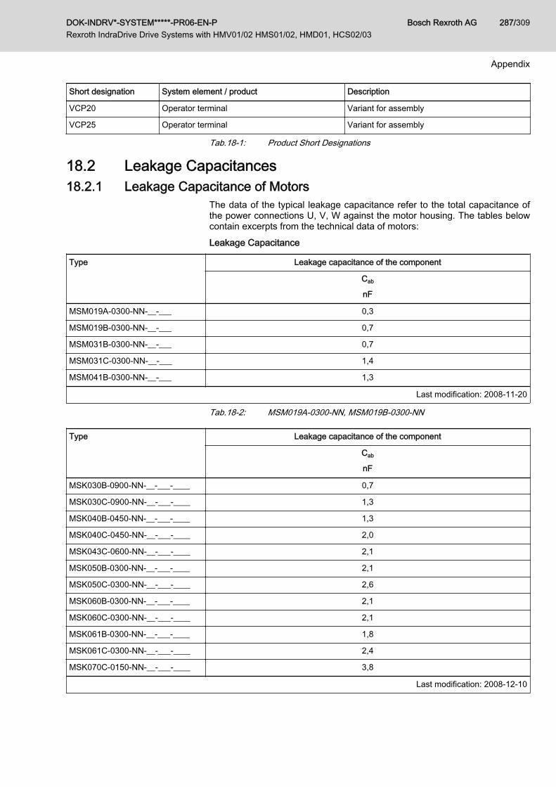
Short designation System element / product Description
VCP20 Operator terminal Variant for assembly
VCP25 Operator terminal Variant for assembly
Tab.18-1: Product Short Designations
18.2 Leakage Capacitances18.2.1 Leakage Capacitance of Motors
The data of the typical leakage capacitance refer to the total capacitance ofthe power connections U, V, W against the motor housing. The tables belowcontain excerpts from the technical data of motors:Leakage Capacitance
Type Leakage capacitance of the component
Cab
nF
MSM019A-0300-NN-__-___ 0,3
MSM019B-0300-NN-__-___ 0,7
MSM031B-0300-NN-__-___ 0,7
MSM031C-0300-NN-__-___ 1,4
MSM041B-0300-NN-__-___ 1,3
Last modification: 2008-11-20
Tab.18-2: MSM019A-0300-NN, MSM019B-0300-NN
Type Leakage capacitance of the component
Cab
nF
MSK030B-0900-NN-__-___-____ 0,7
MSK030C-0900-NN-__-___-____ 1,3
MSK040B-0450-NN-__-___-____ 1,3
MSK040C-0450-NN-__-___-____ 2,0
MSK043C-0600-NN-__-___-____ 2,1
MSK050B-0300-NN-__-___-____ 2,1
MSK050C-0300-NN-__-___-____ 2,6
MSK060B-0300-NN-__-___-____ 2,1
MSK060C-0300-NN-__-___-____ 2,1
MSK061B-0300-NN-__-___-____ 1,8
MSK061C-0300-NN-__-___-____ 2,4
MSK070C-0150-NN-__-___-____ 3,8
Last modification: 2008-12-10
DOK-INDRV*-SYSTEM*****-PR06-EN-P Rexroth IndraDrive Drive Systems with HMV01/02 HMS01/02, HMD01, HCS02/03
Bosch Rexroth AG 287/309
Appendix

Type Leakage capacitance of the component
Cab
nF
MSK070D-0150-NN-__-___-____ 5,0
MSK070E-0150-NN-__-___-____ 6,3
MSK071C-0200-FN-__-___-____ 4,6
MSK071D-0200-FN-__-___-____ 6,9
MSK071E-0200-FN-__-___-____ 8,9
MSK075C-0200-NN-__-___-____
MSK075D-0200-NN-__-___-____ 4,6
MSK075E-0200-NN-__-___-____ 5,8
MSK076C-0300-NN-__-___-____ 6,5
MSK100A-0200-NN-__-___-____ 4,8
MSK100B-0200-NN-__-___-____ 10,3
MSK100C-0200-NN-__-___-____ 12,8
MSK100D-0200-NN-__-___-____ 17,6
MSK101C-0200-FN-__-___-____ 6,2
MSK101D-0200-FN-__-___-____ 13,2
MSK101E-0200-FN-__-___-____ 15,2
MSK103A-0300-NN-__-___-____ 1,5
MSK103B-0300-NN-__-___-____ 2,1
MSK103D-0300-NN-__-___-____ 6,0
MSK131B-0200-NN-__-___-____ 14,3
MSK131D-0200-NN-__-___-____ 27,7
Last modification: 2008-12-10
Tab.18-3: MSK - Leakage Capacitance (Excerpt)See also Rexroth IndraDyn - Technical Data.
18.2.2 Leakage Capacitance of Power Cables The power cables (bulk cables) of the "RKL" line by Rexroth have the capaci‐tances per unit length listed below. The values refer to the sum of the singlecapacitances of power cores 1, 2 and 3 against the overall shield.For power cables of the "RKH" line (hybrid cable of IndraDrive Mi), the valuerefers to the power cores L+, L- against the overall shield.See also Rexroth Connection Cables - Data Sheet Bulk Cables.
Bosch Rexroth AG DOK-INDRV*-SYSTEM*****-PR06-EN-P Rexroth IndraDrive Drive Systems with HMV01/02 HMS01/02, HMD01, HCS02/03
288/309
Appendix

Data Sheet Excerpt- Bulk Cables
Type Cross section of power core Leakage capacitance
mm2CY_K_typ
nF/m
INK0653 1,0 0,6
INK0650 1,5 0,8
INK0602 2,5 0,7
INK0603 4,0 0,8
INK0604 6,0 0,8
INK0605 10,0 1,0
INK0606 16,0 1,2
INK0607 25,0 1,1
INK0667 35,0 1,2
INK0668 50,0 1,3
Last modification: 2007-11-08
Tab.18-4: INK - Technical Data (Excerpt)Data Sheet Excerpt- Bulk Cables
Type Cross section of power core Leakage capacitanceCY_K_typ
mm2 nF/m
REH0800 2,5 0,2
Tab.18-5: REH - Technical Data (Excerpt)
Approximate calculation is allowed with the following values:● Cross section 1 … 6 mm2: 1 nF/m● Cross section 10 … 50 mm2: 1.2 nF/m
DOK-INDRV*-SYSTEM*****-PR06-EN-P Rexroth IndraDrive Drive Systems with HMV01/02 HMS01/02, HMD01, HCS02/03
Bosch Rexroth AG 289/309
Appendix

18.3 Emitted Harmonics on Mains Current and Mains Voltage18.3.1 General Information
Due to their electric design, the drive controllers and supply units generateharmonics in the mains current and on the mains voltage during operation atthe mains. Using appropriate mains chokes decisively influences power fac‐tors and mains harmonics.
18.3.2 Harmonics of Mains CurrentHarmonics of Supply Units, In‐
feeding (HMV…E and HCS) The harmonics of the mains current are decisively reduced by theuse of mains chokes.
For mains with mains frequency fLN = 60 Hz, the values accord‐ingly are multiples of fLN = 60 Hz.
Formulas see chapter "Calculations".
Without mains choke With HNL Mains chokeWith mains choke of higher in‐
ductance1.7 x LN of HNL
IL_cont 5% 50% 100% 5% 50% 100% 5% 50% 100%
k f Ik/I1 Ik/I1 Ik/I1 Ik/I1 Ik/I1 Ik/I1 Ik/I1 Ik/I1 Ik/I1
Hz % % % % % % % % %
1 50 100% 100% 100% 100% 100% 100% 100% 100% 100%
2 100 3 2 1 2 1 0,2 2 1 0,5
3 150 9 3 2 8 2 1 7 2 1
4 200 1 2 1 1 1 0,2 1 1 0,5
5 250 95 90 85 84 70 61 71 55 38
6 300 3 2 1 2 2 0,5 2 1 0,5
7 350 85 80 75 71 40 36 58 28 13
8 400 3 3 1 1 2 0,5 1 2 0,5
9 450 2 2 1 6 1 1 5 1 0,5
10 500 1 1 1 1 1 0,5 1 1 0,5
11 550 70 60 50 40 6 4,2 27 7 6,5
12 600 1 1 1 1 1 0,5 1 1 1
13 650 46 55 45 28 5 5,1 17 5 3
14 700 2 2 1 1 1 1 2 1 1
15 750 2 1 1 1 1 1 2 1 1
16 800 1 1 1 1 1 0,5 2 1 1
17 850 30 25 20 1 0,5 0,5 6 3 2,5
18 900 1 1 1 1 0,5 0,5 1 1 1
19 950 20 13 10 1 0,5 0,5 7 1 2
Bosch Rexroth AG DOK-INDRV*-SYSTEM*****-PR06-EN-P Rexroth IndraDrive Drive Systems with HMV01/02 HMS01/02, HMD01, HCS02/03
290/309
Appendix
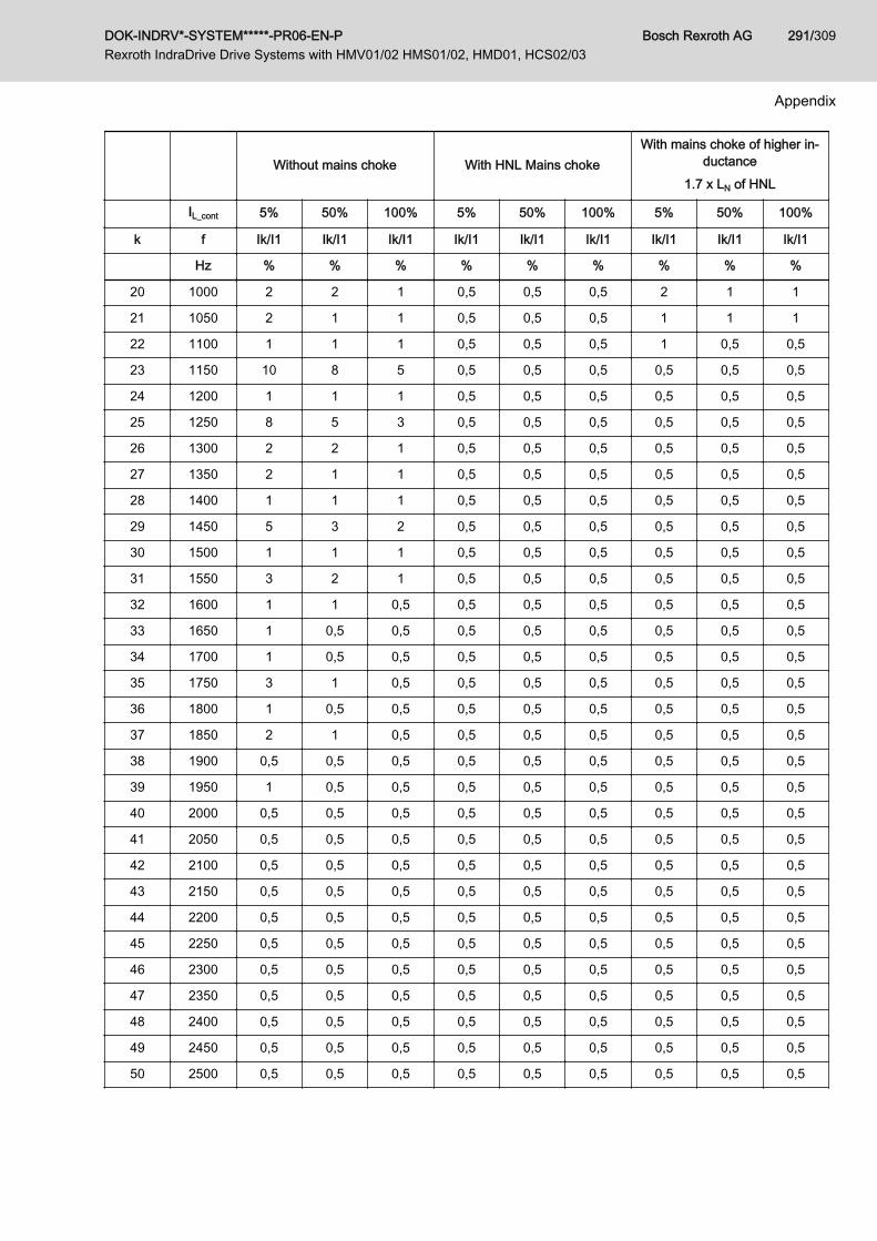
Without mains choke With HNL Mains chokeWith mains choke of higher in‐
ductance1.7 x LN of HNL
IL_cont 5% 50% 100% 5% 50% 100% 5% 50% 100%
k f Ik/I1 Ik/I1 Ik/I1 Ik/I1 Ik/I1 Ik/I1 Ik/I1 Ik/I1 Ik/I1
Hz % % % % % % % % %
20 1000 2 2 1 0,5 0,5 0,5 2 1 1
21 1050 2 1 1 0,5 0,5 0,5 1 1 1
22 1100 1 1 1 0,5 0,5 0,5 1 0,5 0,5
23 1150 10 8 5 0,5 0,5 0,5 0,5 0,5 0,5
24 1200 1 1 1 0,5 0,5 0,5 0,5 0,5 0,5
25 1250 8 5 3 0,5 0,5 0,5 0,5 0,5 0,5
26 1300 2 2 1 0,5 0,5 0,5 0,5 0,5 0,5
27 1350 2 1 1 0,5 0,5 0,5 0,5 0,5 0,5
28 1400 1 1 1 0,5 0,5 0,5 0,5 0,5 0,5
29 1450 5 3 2 0,5 0,5 0,5 0,5 0,5 0,5
30 1500 1 1 1 0,5 0,5 0,5 0,5 0,5 0,5
31 1550 3 2 1 0,5 0,5 0,5 0,5 0,5 0,5
32 1600 1 1 0,5 0,5 0,5 0,5 0,5 0,5 0,5
33 1650 1 0,5 0,5 0,5 0,5 0,5 0,5 0,5 0,5
34 1700 1 0,5 0,5 0,5 0,5 0,5 0,5 0,5 0,5
35 1750 3 1 0,5 0,5 0,5 0,5 0,5 0,5 0,5
36 1800 1 0,5 0,5 0,5 0,5 0,5 0,5 0,5 0,5
37 1850 2 1 0,5 0,5 0,5 0,5 0,5 0,5 0,5
38 1900 0,5 0,5 0,5 0,5 0,5 0,5 0,5 0,5 0,5
39 1950 1 0,5 0,5 0,5 0,5 0,5 0,5 0,5 0,5
40 2000 0,5 0,5 0,5 0,5 0,5 0,5 0,5 0,5 0,5
41 2050 0,5 0,5 0,5 0,5 0,5 0,5 0,5 0,5 0,5
42 2100 0,5 0,5 0,5 0,5 0,5 0,5 0,5 0,5 0,5
43 2150 0,5 0,5 0,5 0,5 0,5 0,5 0,5 0,5 0,5
44 2200 0,5 0,5 0,5 0,5 0,5 0,5 0,5 0,5 0,5
45 2250 0,5 0,5 0,5 0,5 0,5 0,5 0,5 0,5 0,5
46 2300 0,5 0,5 0,5 0,5 0,5 0,5 0,5 0,5 0,5
47 2350 0,5 0,5 0,5 0,5 0,5 0,5 0,5 0,5 0,5
48 2400 0,5 0,5 0,5 0,5 0,5 0,5 0,5 0,5 0,5
49 2450 0,5 0,5 0,5 0,5 0,5 0,5 0,5 0,5 0,5
50 2500 0,5 0,5 0,5 0,5 0,5 0,5 0,5 0,5 0,5
DOK-INDRV*-SYSTEM*****-PR06-EN-P Rexroth IndraDrive Drive Systems with HMV01/02 HMS01/02, HMD01, HCS02/03
Bosch Rexroth AG 291/309
Appendix
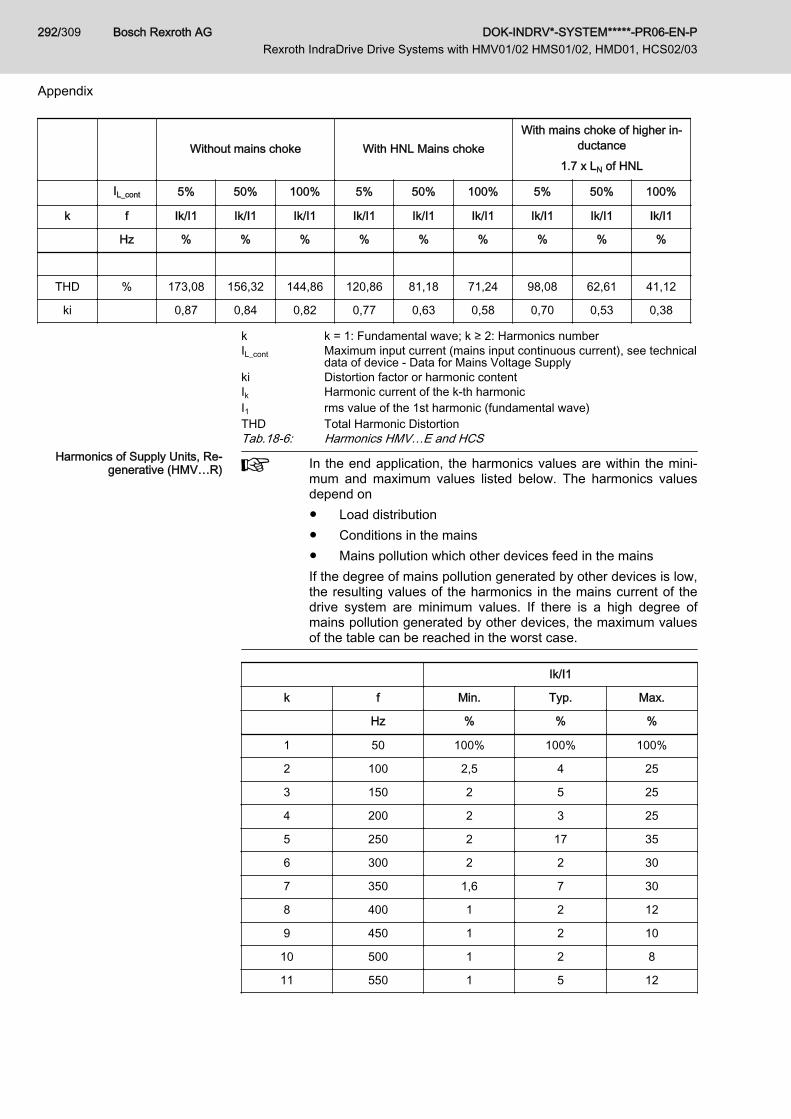
Without mains choke With HNL Mains chokeWith mains choke of higher in‐
ductance1.7 x LN of HNL
IL_cont 5% 50% 100% 5% 50% 100% 5% 50% 100%
k f Ik/I1 Ik/I1 Ik/I1 Ik/I1 Ik/I1 Ik/I1 Ik/I1 Ik/I1 Ik/I1
Hz % % % % % % % % %
THD % 173,08 156,32 144,86 120,86 81,18 71,24 98,08 62,61 41,12
ki 0,87 0,84 0,82 0,77 0,63 0,58 0,70 0,53 0,38
k k = 1: Fundamental wave; k ≥ 2: Harmonics numberIL_cont Maximum input current (mains input continuous current), see technical
data of device - Data for Mains Voltage Supplyki Distortion factor or harmonic contentIk Harmonic current of the k-th harmonicI1 rms value of the 1st harmonic (fundamental wave)THD Total Harmonic DistortionTab.18-6: Harmonics HMV…E and HCS
Harmonics of Supply Units, Re‐generative (HMV…R) In the end application, the harmonics values are within the mini‐
mum and maximum values listed below. The harmonics valuesdepend on● Load distribution● Conditions in the mains● Mains pollution which other devices feed in the mainsIf the degree of mains pollution generated by other devices is low,the resulting values of the harmonics in the mains current of thedrive system are minimum values. If there is a high degree ofmains pollution generated by other devices, the maximum valuesof the table can be reached in the worst case.
Ik/I1
k f Min. Typ. Max.
Hz % % %
1 50 100% 100% 100%
2 100 2,5 4 25
3 150 2 5 25
4 200 2 3 25
5 250 2 17 35
6 300 2 2 30
7 350 1,6 7 30
8 400 1 2 12
9 450 1 2 10
10 500 1 2 8
11 550 1 5 12
Bosch Rexroth AG DOK-INDRV*-SYSTEM*****-PR06-EN-P Rexroth IndraDrive Drive Systems with HMV01/02 HMS01/02, HMD01, HCS02/03
292/309
Appendix
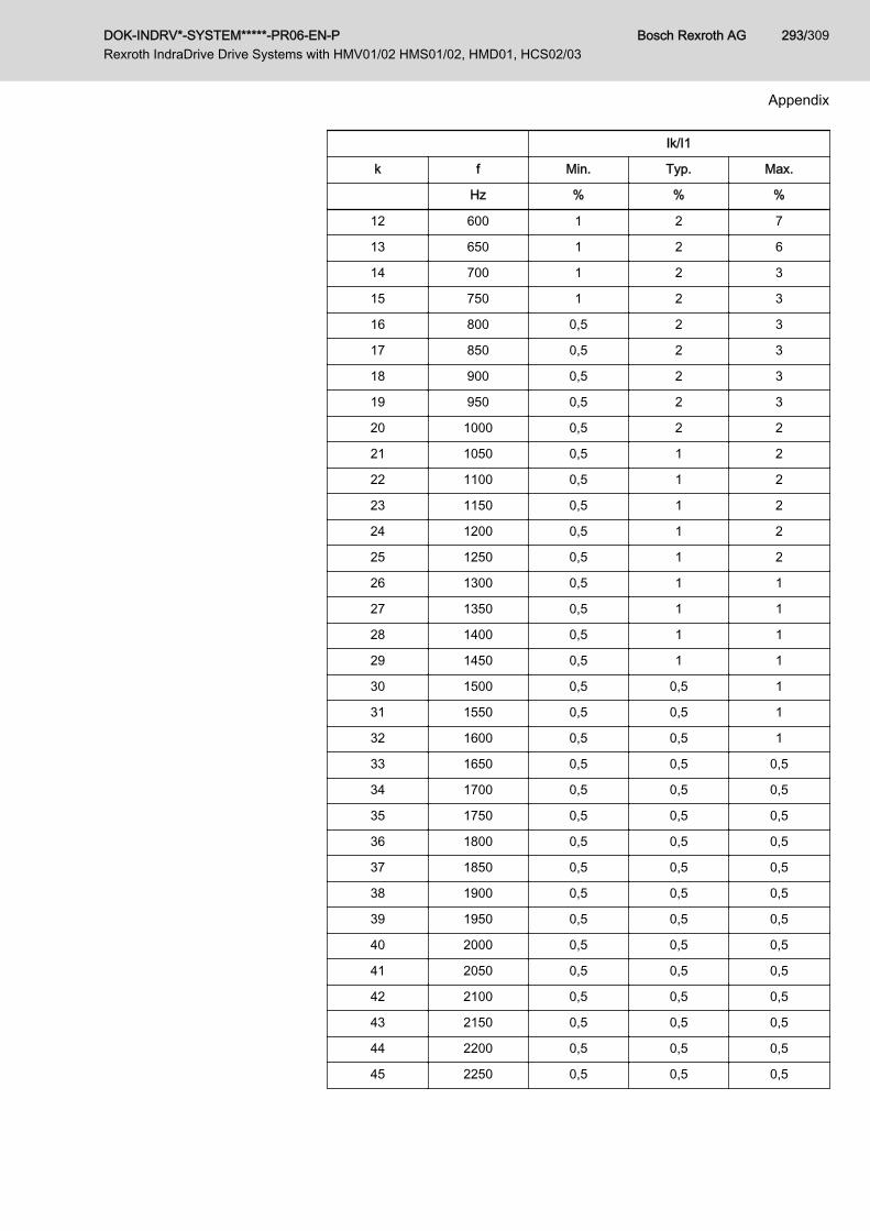
Ik/I1
k f Min. Typ. Max.
Hz % % %
12 600 1 2 7
13 650 1 2 6
14 700 1 2 3
15 750 1 2 3
16 800 0,5 2 3
17 850 0,5 2 3
18 900 0,5 2 3
19 950 0,5 2 3
20 1000 0,5 2 2
21 1050 0,5 1 2
22 1100 0,5 1 2
23 1150 0,5 1 2
24 1200 0,5 1 2
25 1250 0,5 1 2
26 1300 0,5 1 1
27 1350 0,5 1 1
28 1400 0,5 1 1
29 1450 0,5 1 1
30 1500 0,5 0,5 1
31 1550 0,5 0,5 1
32 1600 0,5 0,5 1
33 1650 0,5 0,5 0,5
34 1700 0,5 0,5 0,5
35 1750 0,5 0,5 0,5
36 1800 0,5 0,5 0,5
37 1850 0,5 0,5 0,5
38 1900 0,5 0,5 0,5
39 1950 0,5 0,5 0,5
40 2000 0,5 0,5 0,5
41 2050 0,5 0,5 0,5
42 2100 0,5 0,5 0,5
43 2150 0,5 0,5 0,5
44 2200 0,5 0,5 0,5
45 2250 0,5 0,5 0,5
DOK-INDRV*-SYSTEM*****-PR06-EN-P Rexroth IndraDrive Drive Systems with HMV01/02 HMS01/02, HMD01, HCS02/03
Bosch Rexroth AG 293/309
Appendix

Ik/I1
k f Min. Typ. Max.
Hz % % %
46 2300 0,5 0,5 0,5
47 2350 0,5 0,5 0,5
48 2400 0,5 0,5 0,5
49 2450 0,5 0,5 0,5
50 2500 0,5 0,5 0,5
THD % 6,45 21,89 74,34
ki 0,06 0,21 0,60
Min. Values in the case of a low degree of mains pollution by other devicesTyp. Values in the case of standard applications in industrial mainsMax. Values in the case of a high degree of mains pollution by other devi‐
cesk k = 1: Fundamental wave; k ≥ 2: Harmonics numberIL_cont Maximum input current (mains input continuous current), see technical
data of device - Data for Mains Voltage Supplyki Distortion factor or harmonic contentIk Harmonic current of the k-th harmonicI1 rms value of the 1st harmonic (fundamental wave)THD Total Harmonic DistortionTab.18-7: Harmonics HMV01.1R
18.3.3 Harmonics on Mains VoltageThe voltage harmonics depend on the structure of the mains, especially onthe mains inductance or the mains short-circuit power at the connection point.At different mains and mains connection points, one device can cause differ‐ent voltage harmonics.For a normal mains, the harmonics content of the mains voltage when ope‐rating drives generally is below 10%. Short-time drops in mains voltage arebelow 20%.More precise values can only be calculated with exact knowledge of themains data (mains topology), such as line inductance and line capacitancerelated to the connection point.These values, however, can temporally vary quite strongly, according to theswitch status of the mains. The harmonics of the mains voltage therebychange, too.Rough estimated values of the mains data are not sufficient for pre-calcula‐tion of the harmonics, as mainly the resonance points always present in themains have a strong influence on the harmonics content.In order to keep the degree of mains voltage harmonics as low as possible,you should, if possible, not connect capacitors or compensation units (capaci‐tor batteries) directly to the mains. If capacitors or compensation units are ab‐solutely required, you should only connect them to the mains via chokes.
18.4 Voltage Pulse for Test According to EN61000The figure below shows the voltage pulse for defining the impulse withstandvoltage according to EN61000.
Bosch Rexroth AG DOK-INDRV*-SYSTEM*****-PR06-EN-P Rexroth IndraDrive Drive Systems with HMV01/02 HMS01/02, HMD01, HCS02/03
294/309
Appendix

Fig.18-1: Impulse Withstand Voltage 1.2 / 50 μs and 8 / 20 μs According to EN61000
DOK-INDRV*-SYSTEM*****-PR06-EN-P Rexroth IndraDrive Drive Systems with HMV01/02 HMS01/02, HMD01, HCS02/03
Bosch Rexroth AG 295/309
Appendix

18.5 Discharging of Capacitors18.5.1 Discharging DC Bus Capacitors
Capacitors as Energy Stores In the drive system Rexroth IndraDrive, capacitors are used in the DC bus asenergy stores. In drive controllers and particularly in supply units, such ca‐pacitors have already been integrated.Energy stores maintain their energy even when the supply voltage has beencut off and have to be discharged before somebody gets in contact withthem.If additional capacitors (such as DC bus capacitor units) are connected, thesecapacitors, too, have to be discharged before somebody gets in contact withthem.
Discharge Time Discharging devices have been integrated in the components of the drivesystem Rexroth IndraDrive; within the indicated discharge time, these devi‐ces discharge the voltage below the allowed 50 V.Due to the operating principle, the discharge time is the longer● the bigger the energy store (the capacitance value)● the higher the voltage to which the energy store has been charged● the greater the resistance for discharging the capacitorsComponents of the drive system Rexroth IndraDrive have been dimensionedin such a way that after the supply voltage was cut off, the voltage value fallsbelow 50 V within a discharge time of a maximum of 30 minutes.
HMV01 and ZKS When using HMV01 supply units (exception: HMV01.1R-W0120), you cantake the following measure to shorten the waiting time until the voltage hasfallen below 50 V:Activate the "ZKS" function (ZKS = DC bus short circuit)
Bosch Rexroth AG DOK-INDRV*-SYSTEM*****-PR06-EN-P Rexroth IndraDrive Drive Systems with HMV01/02 HMS01/02, HMD01, HCS02/03
296/309
Appendix
Glossary, Definitions of Terms, Abbreviations
AccessoriesThe accessories are assigned to the corresponding device in order to supportits functioning. For example, the basic accessories belong to each drive con‐troller and supply unit to fasten them and connect them electrically.
Additional componentsAdditional components complement supply units, converters and inverters.Typical additional components are mains chokes, mains filters and brakingresistors, for example.
Basic control section circuit boardThe basic control section circuit board is the main part of the control section.It has its own interfaces and, in the case of configurable control sections, ad‐ditional optional slots for optional modules.
Brake chopperElectronics used to control a braking resistor.
Braking resistorDuring deceleration, a braking resistor converts the kinetic energy of a motorinto thermal energy. When the response voltage is exceeded, the braking re‐sistor is connected to the DC bus voltage by the brake chopper.
CableA cable is a combination of several strands which is kept together by the ca‐ble jacket. A typical type of cable is the cable for the motor connection.
Capacitance against housingDrive controllers and supply units have capacitances against housing Cywhich are primarily determined by capacitors at the DC bus (L+, L-). In thedrive system, these capacitors form a low-impedance path back to the devicefor the leakage currents.
Closed-loop (CL)Closed-loop describes the closed-loop-controlled operation of motors, for ex‐ample with field-oriented control. This operation is possible both in sensorlessform and with encoder and is distinguished with regard to its applications.Sensorless, i.e. without additional encoder, for velocity control, for exampleby means of observer.With encoder, i.e. with additional encoder, for velocity and position control ofsynchronous motors and asynchronous motors in field-oriented operation.
DOK-INDRV*-SYSTEM*****-PR06-EN-P Rexroth IndraDrive Drive Systems with HMV01/02 HMS01/02, HMD01, HCS02/03
Bosch Rexroth AG 297/309
Glossary, Definitions of Terms, Abbreviations
CombinationCombination refers to a combination of components which is formed via acommon DC bus or common mains connection. Components such as mainschoke, mains transformer and mains filter are used in common.
Common DC busVoltage source backed up with powerful capacitors to supply drive controllerswith power voltage. "Common" means that the DC bus connections of the in‐volved devices are interconnected.
ConfigurationConfiguration describes a specific combination of optional modules to form aconfigured control section which is ideally suited for the intended application.
Connection point of equipment grounding conductorThe connection point of the equipment grounding conductor is the connectionpoint at which the equipment grounding conductor is fixed to the component;
the connection point is identified with the symbol .
Control panelA control panel is a unit for operating a device. A control panel has input andoutput elements, such as a key panel and a display.
Control sectionThe control section is a separate component which is plugged into the powersection. The control section processes the signals of the connected compo‐nents (field bus, encoder system, control panel, etc.). Control sections differwith regard to their performance, function and configuration.
Converter, frequency converterDrive controller which generates three-phase alternating voltage with variableamplitude and frequency from the mains voltage with fixed amplitude and fre‐quency in order to set the speed of three-phase a.c. motors, for example.Contains the fundamental stages mains rectifier, DC bus and inverter.
DisplayThe display is part of the control panel for visual output of information.
Drive controllerDevice with which a motor can be operated. Umbrella term for converter orinverter.
Electric drive systemAn electric drive system is the entirety of interconnected hardware, firmwareand software components that have an influence on the sequence of motionsof an installation or machine. The electric drive system consists of, for exam‐ple, supply units, drive controllers, plug-in control units, motors, encoder sys‐
Bosch Rexroth AG DOK-INDRV*-SYSTEM*****-PR06-EN-P Rexroth IndraDrive Drive Systems with HMV01/02 HMS01/02, HMD01, HCS02/03
298/309
Glossary, Definitions of Terms, Abbreviations

tems, as well as auxiliary and additional components (mains filter, mainschoke, braking resistors, etc.).
EncoderPart of an electric drive system which determines the actual value of a valueto be controlled.
Equipment grounding conductorThe equipment grounding conductor establishes the conductive connectionfrom the connection point of the equipment grounding conductor of the com‐ponent to the equipment grounding system.
Equipment grounding systemThe equipment grounding system is the entire equipment by which the equip‐ment grounding conductors of components are connected to the equipmentgrounding conductor of the mains. In the majority of cases, an earth-circuitconnector belongs to the equipment grounding system.
FMEAFailure Mode and Effects Analysis
Hybrid cableIn a hybrid cable, both electrical signals are transmitted on copper wires andoptical signals are transmitted on fiber optic cables.
InverterDevice which generates three-phase alternating voltage with variable ampli‐tude and frequency from the DC bus direct voltage.
Leakage capacitanceThe capacitances which generate so-called leakage currents against groundat the outputs of inverters are regarded as leakage capacitance Cab.The total value of the leakage capacitance is mainly determined by the ca‐pacitances in output filters, capacitances of the motor cables (capacitanceper unit length against shield and ground wire) and the capacitances of mo‐tors (winding capacitance against housing).
LineA line consists of an electric conductor and its insulation. Sheathed lines arealso called cables.
Master communicationMaster communication is the specific communication between hierarchicalcommunication levels. By means of master communication, command varia‐bles (e.g., command values) are transmitted from a higher-level control unitto receivers, and actual values, for example, are transmitted back to the con‐trol unit.
DOK-INDRV*-SYSTEM*****-PR06-EN-P Rexroth IndraDrive Drive Systems with HMV01/02 HMS01/02, HMD01, HCS02/03
Bosch Rexroth AG 299/309
Glossary, Definitions of Terms, Abbreviations

Open-loop (OL)Open-loop describes the open-loop-controlled operation of asynchronousmotors at frequency converters in V/Hz [U/f] operation without encoder at themotor. This is the simplest operation of asynchronous motors.
Optional moduleBy means of optional modules, configurable control sections are equippedwith various functions. For example, there are optional modules for mastercommunications (e.g., SERCOS), encoder evaluations, I/O extensions, safetytechnologies, control panels and storage media.
Optional slotSlot in the control section into which an optional module can be plugged. On‐ly configurable control sections have optional slots.
PELV"Protectiv Extra Low Voltage" circuits provide protection against electricshock and according to standard must comply with specific requirements.Among other things, live parts and exposed conductive parts of PELV circuitsmust be separated from the primary circuit by means of double or reinforcedinsulation.
Power sectionThe power section is a separate component which contains all the importantpower elements of the drive controller. Power section and control sectionform a drive controller.
SCCRShort Circuit Current Ratio
SMPSSwitched Mode Power Supply
Supply unitDevice which provides power supply to drive controllers. For disconnectionfrom the supply mains, it often contains a mains contactor or provides the sig‐nals required to control an external mains contactor.
Third-party supply unitSupply units which do not belong to the "Rexroth IndraDrive" product range.
UPSAn uninterruptible power supply is used to ensure the supply of electric loadsin the case of disturbances in the power network.
V/Hz [U/f] operationOperation in which the drive controller generates variable voltage and fre‐quency in order to set the speed of three-phase a.c. motors, for example.
Bosch Rexroth AG DOK-INDRV*-SYSTEM*****-PR06-EN-P Rexroth IndraDrive Drive Systems with HMV01/02 HMS01/02, HMD01, HCS02/03
300/309
Glossary, Definitions of Terms, Abbreviations

Index0 … 924V control voltage supply.................................. 6724V supply
Continuous power.......................................... 69Determining the data for selection................. 67Installation...................................................... 70Peak current................................................... 69Specification................................................... 65
AAbbreviations.................................................... 285Acceptance tests................................................. 55Accessories HAS
Brief description............................................. 52Accumulators.................................................... 281Additional components
Arrangement................................................ 202At the DC Bus.............................................. 120At the motor output...................................... 125For supply units and converters................... 120
Additional documentations.................................. 29Additional external capacitors
Calculations................................................. 252Ambient conditions.............................................. 58ANAX................................................................ 136Applications
Drive system Rexroth IndraDrive................... 47Appropriate use................................................... 35
Applications.................................................... 35Approvals............................................................ 55Arrangement
Performance-dependent.............................. 202
BBatteries............................................................ 281Bb contact
Circuit........................................................... 141Configuration Rel 1...................................... 145Properties..................................................... 142
Bb ContactLoad capability limits.................................... 142
Bonding conductor............................................ 240Boring dimensions
For the mounting plate................................. 194Braking resistor
Continuous power........................................ 256Duty cycle.................................................... 257Duty cycle, relative....................................... 257Energy absorption........................................ 252Peak power.................................................. 258
Braking resistor HLR01Brief description............................................. 51
BranchFusing.......................................................... 266
CC-UL-US listing................................................... 55C-UR-US listing................................................... 56Cables
Capacitance................................................. 288Connection cables to motor......................... 137Documentation............................................... 31Leakage capacitance................................... 288
Calculations...................................................... 247Additional external capacitors...................... 252Charging the DC bus................................... 276Continuous power in the common DC bus. . 263Continuous regenerative power................... 255Control factor............................................... 258DC bus continuous power............................ 247DC bus peak power..................................... 251Distortion factor............................................ 261DPF.............................................................. 262Harmonic content......................................... 261Inrush current............................................... 261Leakage capacitance................................... 272Mains choke HNL......................................... 264Mains connection......................................... 260Mains filter: Allowed operating data............. 273Mains harmonics.......................................... 261Mains-side phase current............................. 260Peak regenerative power............................. 257Phase current............................................... 260Power dissipation......................................... 252Power factor cosφ........................................ 262Power factor cosφ1...................................... 262Regenerative power..................................... 251Speed characteristic and braking timewith DC bus short circuit (ZKS).................... 277TPF (λ)......................................................... 262Wattless power load..................................... 262
CapacitanceAgainst housing Cy...................................... 113Capacitance per unit length (motor powercable)........................................................... 139Motors.......................................................... 287Power cables............................................... 288
CapacitorsDischarging.................................................. 296
CCC, China Compulsory Certification................. 57CDB
Brief description............................................. 49CDB control section
Usage............................................................. 50CE label.............................................................. 55Central supply
HCS............................................................... 99HMV............................................................... 96
Certifications....................................................... 55Changes
DOK-INDRV*-SYSTEM*****-PR06-EN-P Rexroth IndraDrive Drive Systems with HMV01/02 HMS01/02, HMD01, HCS02/03
Bosch Rexroth AG 301/309
Index

Documentation............................................... 28Characteristic
Fuses........................................................... 271Charging resistance
HCS02......................................................... 276HCS03......................................................... 277
Charging the DC busCalculations................................................. 276
China Compulsory Certification (CCC)............... 57Circuit
Deceleration in the case of disturbedelectronic system of drive (DC bus shortcircuit is activated)....................................... 155Deceleration in the case of emergencystop or mains failure..................................... 166For mains connection ofRexroth IndraDrive C drive controllers......... 145For mains connection ofRexroth IndraDrive M supply units............... 154For mains connection; HCS02 with DCbus resistor unit HLB01.1C.......................... 148For mains connection; HCS03 with DCbus resistor unit HLB01.1D.......................... 148For the mains connection............................. 141
Circulation......................................................... 193Combination
Firmware, control section, power section..... 126With components of the control rangeRexroth IndraControl V................................ 136With motor filters HMF01............................. 126
Commutation dips............................................... 74Compatibility
With foreign matters....................................... 63Components
Arranging the components in the controlcabinet......................................................... 189Documentations............................................. 29Main dimensions of the system compo‐nents............................................................ 189Mounting positions......................................... 62Performance-dependent arrangement......... 202Short designations....................................... 285
ConditionsAmbient and operating conditions.................. 58
Configuration Rel 1 as Bb contact.................... 145Connected load
Mains, maximum............................................ 82Connection
Control voltage............................................. 232Control voltage connections......................... 232DC bus......................................................... 228DC bus connections..................................... 228Equipment grounding conductor.................. 223Ground connection....................................... 222Mains choke................................................. 226Module bus.................................................. 235Motor............................................................ 236Motor and drive controller............................ 236
Connection cablesTo motor....................................................... 137
Connection linesMinimum requirements................................ 229
ConnectionsIn the drive system....................................... 221
ContactorSelecting...................................................... 265
Contained substancessee "Significant components"...................... 281
Continuous powers in the common DC busCalculations................................................. 263
Continuous regenerative powerCalculations................................................. 255
ControlBy emergency stop relay............................. 169External mains contactor for HCS02 andHCS03......................................................... 145
Control cabinetArea A, interference-free.............................. 207Area B, interference-susceptible.................. 209Area C, strongly interference-susceptible.... 209Arranging the components........................... 189Avoiding moisture condensation.................. 217Cooling......................................................... 215Cooling unit.................................................. 216Design.......................................................... 215Interference areas........................................ 205Multiple-line arrangement of drive con‐trollers.......................................................... 218
Control circuitDeceleration in the case of disturbedelectronic system of drive (DC bus shortcircuit is activated)....................................... 155Deceleration in the case of emergencystop or mains failure..................................... 166For mains connection ofRexroth IndraDrive C drive controllers......... 145For mains connection ofRexroth IndraDrive M supply units............... 154For mains connection; HCS02 with DCbus resistor unit HLB01.1C.......................... 148For mains connection; HCS03 with DCbus resistor unit HLB01.1D.......................... 148For the mains connection............................. 141HCS02 converter and HLB01.1C................. 149HCS02 converter and HLB01.1C andemergency stop relay................................... 151HCS03 converter......................................... 153Parallel operation......................................... 155
Control circuit position-controlled shutdownHMV01.1R supply unit with integratedmains contactor............................................ 168
Control circuit with DC bus short circuit (ZKS)HMV01.1R-W0120 supply unit with exter‐nal mains contactor...................................... 165Supply unit HMV01.1E with integratedmains contactor............................................ 159
Bosch Rexroth AG DOK-INDRV*-SYSTEM*****-PR06-EN-P Rexroth IndraDrive Drive Systems with HMV01/02 HMS01/02, HMD01, HCS02/03
302/309
Index

Supply unit HMV01.1R with integratedmains contactor.................................... 161, 163
Control circuit without DC bus short circuit (ZKS)HMV01.1E supply unit with integratedmains contactor............................................ 170HMV01.1R supply unit with integratedmains contactor............................................ 172HMV01.1R supply unit without integratedmains contactor............................................ 174HMV02.1R supply unit with integratedmains contactor............................................ 176
Control factorCalculations................................................. 258
Control sectionIn drive controller........................................... 25
Control sectionsBrief description............................................. 49
Control voltageConnection................................................... 232Specification................................................... 65Supply with control voltage 24 V.................... 67
Control voltage supplyBuffering, UPS............................................... 67Loop-through contacts................................... 71
Convection........................................................ 193Cooling system
Project planning........................................... 215Cooling unit
Arrangement................................................ 216Corner-grounded delta mains............................. 79CSB
Brief description............................................. 49CSB control section
Usage............................................................. 50CSE
Brief description............................................. 49CSE control section
Usage............................................................. 50CSH
Brief description............................................. 49CSH control section
Usage............................................................. 50Cy
Capacitance against housing....................... 113
DData
Ambient conditions......................................... 58Operating conditions...................................... 58
DC busConnection................................................... 228
DC bus capacitor unit HLC01Brief description............................................. 52
DC bus capacitorsDischarging.................................................. 296
DC bus continuous powerCalculations................................................. 247
DC bus peak powerCalculations................................................. 251
DC bus resistor unitHLB01, brief description................................. 51
DC bus short circuit (ZKS)Calculating speed characteristic andbraking time................................................. 277
DC bus short circuit ZKS................................... 155Deceleration
In the case of disturbed electronic systemof drive (DC bus short circuit is activated). . . 155In the case of emergency stop; controlcircuit............................................................ 166In the case of mains failure; control circuit... 166
Declaration of conformity.................................... 55Derating vs. installation altitude
Overvoltage limiter................................... 60, 61Devices
Mounting positions......................................... 62Short designations....................................... 285
DimensioningLine cross sections and fuses...................... 266
DimensionsMain dimensions of the system compo‐nents............................................................ 189
DischargingDC bus capacitors........................................ 296
Disposal............................................................ 281Distance
Between the devices.................................... 190Lateral.......................................................... 193To the bottom of the devices........................ 191To the top of the devices.............................. 191
Distortion factor........................................... 83, 290Calculations................................................. 261
DLT................................................................... 265Brief description............................................. 47Selection...................................................... 265
DocumentationCables............................................................ 31Changes......................................................... 28Drive systems................................................ 29Firmware........................................................ 31Motors............................................................ 30Overview........................................................ 29Purpose.......................................................... 28Reference documentations............................ 29System components...................................... 29
DPFCalculations................................................. 262
Drive controllerBasic design................................................... 24Control section............................................... 25Determine appropriate drive controller......... 247HCS02, brief description................................ 50HCS03, brief description................................ 50HMD01, brief description............................... 49HMS01, brief description................................ 49
DOK-INDRV*-SYSTEM*****-PR06-EN-P Rexroth IndraDrive Drive Systems with HMV01/02 HMS01/02, HMD01, HCS02/03
Bosch Rexroth AG 303/309
Index

HMS02, brief description................................ 49Power section................................................ 24
Drive controllersMultiple-line arrangement............................ 218
Drive system....................................................... 37Combination of components.......................... 93Configuration.................................................. 93Connections................................................. 221Rexroth IndraDrive C..................................... 12Rexroth IndraDrive M..................................... 14Rexroth IndraDrive Mi.................................... 17
Drive system Rexroth IndraDriveApplications.................................................... 47
DSTBrief description............................................. 47
Duty cycle EDRelative........................................................ 257
EElectric drive system........................................... 37Electromagnetic compatibility (EMC)................ 181EMC
Declaration of EMC conformity.................... 186Electromagnetic compatibility...................... 181Ensuring the requirements........................... 186Filtering........................................................ 187Grounding.................................................... 187Limit values for line-based disturbances...... 183Measures for design and installation........... 203Measures to reduce noise emission............ 187Noise emission of the drive system............. 182Noise immunity............................................ 181Requirements............................................... 181Shielding...................................................... 187
Emergency stop relayControl without DC bus short circuit (ZKS). . 169
EMIElectromagnetic interference....................... 181
EncoderCables.......................................................... 140Optional module encoder evaluation........... 133
EnDatEncoder evaluation...................................... 133
Environmental protection.................................. 281ePlan macros.................................................... 240Equipment grounding conductor
Connection............................................. 89, 223Connections................................................. 223Cross section............................................... 225
External wiring.................................................. 271
FFan unit HAB01
Brief description............................................. 52Field wiring........................................................ 271Fields of application
Drive system Rexroth IndraDrive................... 47
File numbersUL.................................................................. 55
FirmwareDocumentation............................................... 31KMS01......................................................... 132KMS02......................................................... 132KSM01......................................................... 132KSM02......................................................... 132
Firmware versionConverter HCS01......................................... 130Converters HCS02, HCS03, HCS04............ 131HCQ02......................................................... 132IndraDrive Mi................................................ 132Inverters HMS01, HMS02, HMD01.............. 128KMS01......................................................... 132KMS02......................................................... 132KSM01......................................................... 132KSM02......................................................... 132Required for control section......................... 127Required for motor....................................... 133Required for power section.......................... 128
FNN2Supply unit..................................................... 97
Foreign mattersCompatibility.................................................. 63
Functions............................................................ 28Fuses
Characteristic............................................... 271Circuit breaker.............................................. 271Design.......................................................... 271Dimensioning............................................... 266
FusingAnd mains contactor.................................... 265Selecting...................................................... 265
GG1, G2, G3, G4, G5
Mounting positions......................................... 62Glossary............................................................... IXGround connection
Of Housing................................................... 222Ground connections.......................................... 211
HHAB01
Brief description............................................. 52HAC01
Brief description............................................. 52Hall sensor box SHL
Brief description............................................. 52Encoder evaluation...................................... 133
Harmonic content.............................................. 290Calculations................................................. 261
HarmonicsEmitted......................................................... 290Mains current............................................... 290Mains voltage............................................... 294
Bosch Rexroth AG DOK-INDRV*-SYSTEM*****-PR06-EN-P Rexroth IndraDrive Drive Systems with HMV01/02 HMS01/02, HMD01, HCS02/03
304/309
Index
HASBrief description............................................. 52
HAS02Shield connection with accessory HAS02.... 237
HAS04Use............................................................... 113
Hazardous substances..................................... 281HCS
Central supply................................................ 99Parallel operation......................................... 104Supply unit..................................................... 99
HCS02Brief description............................................. 50Supply unit for HMS/HMD............................ 101Supply unit for KCU and KSM/KMS............. 101
HCS03Brief description............................................. 50Supply unit for HMS01/HMD01.................... 102
Hierarchical levelsRexroth IndraDrive......................................... 11
HIPERFACE..................................................... 133HLB
Selection aid................................................ 122HLB01
Brief description............................................. 51HLC01
Brief description............................................. 52HLR
Selection aid................................................ 122HLR01
Brief description............................................. 51For HCS02................................................... 124For HCS03................................................... 124
HMD01Brief description............................................. 49
HMF01Motor filter, assignment................................ 126Motor filter, brief description........................... 52
HMS01Brief description............................................. 49
HMS02Brief description............................................. 49
HMVCentral supply................................................ 96
HMV01Brief description............................................. 49
HMV02Brief description............................................. 49
HNFBrief description............................................. 47
HNF01HAS04 required........................................... 113Minimum capacitance.................................. 113
HNKBrief description............................................. 47
HNLBrief description............................................. 48
HNS02
Brief description............................................. 47Housing for control sections HAC01
Brief description............................................. 52
IImpulse withstand voltage................................. 294Inappropriate use................................................ 36
Consequences, exclusion of liability.............. 35IndraDyn H........................................................ 140Inductance per unit length................................. 139Industrial sectors................................................. 47Inrush current
Calculations................................................. 261Installation
EMC measures............................................ 203Ground connections..................................... 211Signal lines................................................... 212
Installation conditions.......................................... 58Installation methods.......................................... 272Installation type
B1......................................................... 267, 270B2......................................................... 268, 270E........................................................... 269, 270NFPA........................................................... 270UL508A........................................................ 270
Insulation monitoring........................................... 66Insulation monitoring devices.............................. 92Insulation resistance test.................................... 64Internal wiring.................................................... 271ISCCR
Short-circuit current ratio................................ 80Isolating transformer
DLT.............................................................. 265IT mains type...................................................... 77
Kk
Distortion factor............................................ 290KCU02
Supplied by HCS02...................................... 101
LLeakage capacitance........................................ 299
Calculations................................................. 272Determining.................................................. 272Motors.......................................................... 287Power cables............................................... 288
Leakage currentsCause............................................................. 90
Limit valuesFor line-based disturbances......................... 183For noise immunity....................................... 182
LineCorrection factor.......................................... 271Cross sections, dimensioning...................... 266Fuses, dimensioning.................................... 266
Listing
DOK-INDRV*-SYSTEM*****-PR06-EN-P Rexroth IndraDrive Drive Systems with HMV01/02 HMS01/02, HMD01, HCS02/03
Bosch Rexroth AG 305/309
Index

C-UL-US........................................................ 55C-UR-US........................................................ 56
MMains
Grounded via outer conductor....................... 79Maximum connected load.............................. 82Measures for compliance with allowedTHD or distortion factor.................................. 83Selecting mains connection components....... 84
Mains chokeBrief description............................................. 48Connection................................................... 226Determining.................................................. 264Selection...................................................... 264
Mains circuit breakerSelecting...................................................... 265
Mains classes..................................................... 80Mains connection
Calculations................................................. 260Circuit........................................................... 141Circuit for Rexroth IndraDrive C drivecontrollers.................................................... 145Circuit for Rexroth IndraDrive M drivecontrollers.................................................... 154Control circuit............................................... 141Control circuit for Rexroth IndraDrive Cdrive controllers............................................ 145Control circuit for Rexroth IndraDrive Mdrive controllers............................................ 154HCS converters............................................ 113HMV supply units......................................... 109Mains connected load.................................... 81Project planning............................................. 73Protection systems......................................... 84Requirements................................................. 73Transformer, mains filter, mains choke........ 106With HNL mains chokes, HNF mains fil‐ters and HNK mains chokes........................ 106
Mains contactorAdditional..................................................... 144And Fusing................................................... 265Circuit........................................................... 141Control of external mains contactor forHCS02 und HCS03...................................... 145Redundant................................................... 144Selecting...................................................... 265Suppressor circuit........................................ 143
Mains filterBrief description............................................. 47Connection................................................... 226Determining.................................................. 264Motor fan...................................................... 208Operating data, allowed............................... 273Other loads.................................................. 208Selection...................................................... 264
Mains harmonics................................................. 74
Calculations................................................. 261Emitted......................................................... 290
Mains overvoltagesMaximum allowed.......................................... 75
Mains short circuitMains short circuit ratio.................................. 82Mains short-circuit current.............................. 80Mains short-circuit power............................... 80
Mains transformerSelection...................................................... 265
Mains transformersBrief description............................................. 47
Mains types......................................................... 76Mains voltage
Harmonics.................................................... 294Mains voltage unbalance.................................. 262Mains-side phase current
Calculating................................................... 260Master-slave..................................................... 155Measures of radio interference suppression
For relays, contactors, switches, chokes,inductive loads............................................. 212
Minimum capacitanceAt the DC bus............................................... 113Use of HNF01.............................................. 113
Minimum inductance........................................... 81Module bus
Connection................................................... 235Moisture condensation
Avoiding....................................................... 217Motor
Capacitance................................................. 287Connection................................................... 236Documentation............................................... 30Encoder evaluation...................................... 133IndraDyn H................................................... 140Leakage capacitance................................... 287Third-party motors........................................ 241
Motor cableAllowed length.............................................. 138Connection at drive controller...................... 236Power cable selection.................................. 138
Motor cablesCapacitance per unit length......................... 139Connected in parallel................................... 139Inductance per unit length............................ 139Selection of encoder cables......................... 140Unshielded................................................... 139
Motor cables connected in parallel................... 139Motor fan
Mains filter.................................................... 208Motor filter HMF01
Assignment to HCS...................................... 126Brief description............................................. 52With IndraDyn.............................................. 126
Motor holding brakeVoltage drop................................................. 139
Motor output
Bosch Rexroth AG DOK-INDRV*-SYSTEM*****-PR06-EN-P Rexroth IndraDrive Drive Systems with HMV01/02 HMS01/02, HMD01, HCS02/03
306/309
Index

Additional components................................. 125Motor paint coat
Additional paint coat....................................... 64Mounting
Boring dimensions for the mounting plate.... 194Mounting position
Definition (G1, G2, G3, G4, G5)..................... 62IM B5.............................................................. 63IM V1.............................................................. 63IM V3.............................................................. 63Motor-integrated servo drive.......................... 63
Multiple-line arrangement of drive controllers... 218
NNFD
Brief description............................................. 47NFE
Brief description............................................. 47Noise emission
Measures for reduction................................ 187Of the drive system...................................... 182
Noise immunityLimit values.................................................. 182
Noise immunity in the drive system.................. 181Number of axes
At HMV01..................................................... 111At HMV02..................................................... 112Capacitance against housing Cy................... 95HCS02......................................................... 114HCS03......................................................... 117Orientation guide............................................ 95
OOperating conditions........................................... 58Operation at partial load............................ 260, 266Operation under rated conditions...................... 266Operator terminals
VCP.............................................................. 136Overvoltage limitation
Note on project planning................................ 75Overvoltage limiter
Derating vs. installation altitude............... 60, 61Overvoltage limiters............................................ 75
PPackaging......................................................... 281Parallel operation
HCS02 with HCS02..................................... 102HCS03 with HCS03..................................... 102HMV............................................................... 98HMV01, control circuit.................................. 155Number of components HCS....................... 104
Peak regenerative powerCalculations................................................. 257
PELV................................................................... 41Phase current
Calculating................................................... 260
Power consumptionMaximum....................................................... 69Typical............................................................ 69
Power dissipationCalculations................................................. 252
Power factor cosφCalculations................................................. 262
Power factor cosφ1Calculations................................................. 262
Power factors.................................................... 290Power supply
Switching off................................................. 143Switching on................................................. 143
Power voltagePower voltage supply..................................... 73
Production processes....................................... 281Products
Short designations....................................... 285Project planning
Of cooling system........................................ 215Project Planning Manuals................................... 29Protection systems
At the mains connection................................. 84Protective extra-low voltage................................ 41Protective grounding........................................... 85
RRCCB.................................................................. 89RCD.................................................................... 89RD500
Supply unit................................................... 105Recycling.......................................................... 281Reference documentations................................. 29Regenerative power
Calculations................................................. 251Rel 1
Configuration as Bb contact......................... 145Residual-current-operated circuit breakers......... 89Resolver............................................................ 133Return of products............................................ 281Rexroth IndraDrive
Hierarchical levels.......................................... 11System platform............................................. 11System presentation...................................... 11
Rexroth IndraDrive CDrive system.................................................. 12
Rexroth IndraDrive MDrive system.................................................. 14
Rexroth IndraDrive MiDrive system.................................................. 17
SSafety instructions for electric drives andcontrols............................................................... 37Selection aid
HLB.............................................................. 122HLR.............................................................. 122
DOK-INDRV*-SYSTEM*****-PR06-EN-P Rexroth IndraDrive Drive Systems with HMV01/02 HMS01/02, HMD01, HCS02/03
Bosch Rexroth AG 307/309
Index
sercos analog converter.................................... 136Shield connection
Motor cable.................................................. 236SHL
Brief description............................................. 52Hall sensor box............................................ 133
Short designations............................................ 285Short-circuit current
Symmetrical................................................... 80Short-time interruptions....................................... 74Signal lines
Installation.................................................... 212Signal sequence
When switching on and off........................... 177Significant components..................................... 281Simultaneity factor............................................ 249Smart Energy Mode
Supply unit..................................................... 97Specifications
Of the components......................................... 55Standard motors
Voltage load................................................. 126State-of-the-art.................................................... 35Storage
Of the components......................................... 58Supply
With control voltage 24 V............................... 67With mains voltage......................................... 73With power voltage........................................ 73
Supply unitFNN2 design.................................................. 97HMV01, brief description................................ 49HMV02, brief description................................ 49Smart Energy Mode....................................... 97
SupportSee service hotline....................................... 283
Switching offPower supply............................................... 143Signal sequence.......................................... 177
Switching onPower supply............................................... 143Signal sequence.......................................... 177
System connections.......................................... 221Position........................................................ 222
System elementsProduct overview......................................... 285Short designations....................................... 285
System impedance............................................. 80System platform.................................................. 11System presentation........................................... 11
TTest
Factory-side................................................... 64Insulation resistance...................................... 64Voltage test.................................................... 64
THD..................................................... 83, 261, 290
Third-party motorsAt drive controllers....................................... 241
Third-party supply units..................................... 105Time behaviour
When switching on and off........................... 177TN-C mains type................................................. 76TN-S mains type................................................. 76Total Harmonic Distortion (THD)....................... 261TPF (λ)
Calculations................................................. 262Transport
Of the components......................................... 57TT system........................................................... 78Type current........................................................ 26Type of supply
For power sections......................................... 93Type performance............................................... 26
UUL
File numbers.................................................. 55Listing....................................................... 55, 56Requirement SCCR....................................... 80
Ungrounded mains.............................................. 77UPS
Control voltage supply................................... 67Use
Appropriate use.............................................. 35Inappropriate use........................................... 36
VVCP
Operator terminals....................................... 136Voltage dips........................................................ 74Voltage drop
Connection to motor holding brake.............. 139Voltage pulse.................................................... 294Voltage test......................................................... 64
WWattless power load
Calculations................................................. 262
ZZKS
DC bus short circuit...................................... 155
Bosch Rexroth AG DOK-INDRV*-SYSTEM*****-PR06-EN-P Rexroth IndraDrive Drive Systems with HMV01/02 HMS01/02, HMD01, HCS02/03
308/309
Index

Notes
DOK-INDRV*-SYSTEM*****-PR06-EN-P Rexroth IndraDrive Drive Systems with HMV01/02 HMS01/02, HMD01, HCS02/03
Bosch Rexroth AG 309/309

DOK-INDRV*-SYSTEM*****-PR06-EN-P
Bosch Rexroth AG Electric Drives and Controls P.O. Box 13 57 97803 Lohr, Germany Bgm.-Dr.-Nebel-Str. 2 97816 Lohr, Germany Tel. +49 9352 18 0 Fax +49 9352 18 8400 www.boschrexroth.com/electrics