rf-5800m hh ops manual
DESCRIPTION
Radio comunicacion HF HarrisExcelente manual de operacion del radio de HF Harris 5800TRANSCRIPT

7/21/2019 RF-5800M HH Ops Manual
http://slidepdf.com/reader/full/rf-5800m-hh-ops-manual 1/199
PUBLICATION NUMBER: 10515-0234-4200JULY 2007
Rev. C
RF-5800M-HH EXPORT MULTIBAND
HANDHELD RADIO
OPERATION MANUAL
The material contained herein is subject to U.S. export approval. No export or re-export is permitted without written approval from the U.S. Government.
R

7/21/2019 RF-5800M HH Ops Manual
http://slidepdf.com/reader/full/rf-5800m-hh-ops-manual 2/199

7/21/2019 RF-5800M HH Ops Manual
http://slidepdf.com/reader/full/rf-5800m-hh-ops-manual 3/199
The default Security Level 3 password for this radio is:
2445830
This password can be modified by a Security Level 3 user.
Zeroizing the radio will reset the password to that shown above
(2445830).
For more information on security levels and passwords, refer to
Paragraph 4.4.
CUT HERE
ATTENTION

7/21/2019 RF-5800M HH Ops Manual
http://slidepdf.com/reader/full/rf-5800m-hh-ops-manual 4/199
This page intentionally left blank.

7/21/2019 RF-5800M HH Ops Manual
http://slidepdf.com/reader/full/rf-5800m-hh-ops-manual 5/199
PUBLICATION NUMBER: 10515-0234-4200JULY 2007
Rev. C
RF-5800M-HHEXPORT HANDHELD RADIOOPERATION MANUAL
The material contained herein is subject to U.S. export approval. No export or re-export is permitted without written approval from the U.S. Government.
Copyright © 2007By Harris Corporation
All Rights Reserved
FIRMWARE RELEASE: V6.5
HARRIS CORPORATION RF COMMUNICATIONS DIVISION1680 University Avenue Rochester, New York 14610-1887 USA
Tel: 585-244-5830. Fax: 585-242-4755. http://www.harris.com
R

7/21/2019 RF-5800M HH Ops Manual
http://slidepdf.com/reader/full/rf-5800m-hh-ops-manual 6/199
7/21/2019 RF-5800M HH Ops Manual
http://slidepdf.com/reader/full/rf-5800m-hh-ops-manual 7/199
TABLE OF CONTENTS
Paragraph Page
CHAPTER 1 – EQUIPMENT DESCRIPTION
1.1 SAFETY PRECAUTIONS . . . . . . . . . . . . . . . . . . . . . . . . . . . . . . . . . . . . . . . 1-1
1.2 PURPOSE OF THIS MANUAL. . . . . . . . . . . . . . . . . . . . . . . . . . . . . . . . . . . . 1-2
1.3 EQUIPMENT DESCRIPTION . . . . . . . . . . . . . . . . . . . . . . . . . . . . . . . . . . . . 1-2
1.4 FEATURES . . . . . . . . . . . . . . . . . . . . . . . . . . . . . . . . . . . . . . . . . . . . . . . . . . 1-4
1.5 CONFIGURATIONS. . . . . . . . . . . . . . . . . . . . . . . . . . . . . . . . . . . . . . . . . . . . 1-5
1.6 SPECIFICATIONS . . . . . . . . . . . . . . . . . . . . . . . . . . . . . . . . . . . . . . . . . . . . . 1-6
1.7 VOICE/DATA COMPATIBILITY . . . . . . . . . . . . . . . . . . . . . . . . . . . . . . . . . . . 1-7
1.8 COMPATIBILITY . . . . . . . . . . . . . . . . . . . . . . . . . . . . . . . . . . . . . . . . . . . . . . 1-8
1.9 COMPATIBLE CABLES AND CONNECTORS . . . . . . . . . . . . . . . . . . . . . . . 1-9
CHAPTER 2 – SETUP AND TEARDOWN
2.1 ITEMS INCLUDED WITH THE RF-5800M-HH . . . . . . . . . . . . . . . . . . . . . . . 2-1
2.1.1 Optional Items . . . . . . . . . . . . . . . . . . . . . . . . . . . . . . . . . . . . . . . . . . . . . . . . 2-5
2.2 BATTERY INSTALLATION. . . . . . . . . . . . . . . . . . . . . . . . . . . . . . . . . . . . . . . 2-62.2.1 Battery Safety. . . . . . . . . . . . . . . . . . . . . . . . . . . . . . . . . . . . . . . . . . . . . . . . . 2-6
2.2.2 Antenna Connections. . . . . . . . . . . . . . . . . . . . . . . . . . . . . . . . . . . . . . . . . . . 2-8
2.2.3 Data Cable Connections . . . . . . . . . . . . . . . . . . . . . . . . . . . . . . . . . . . . . . . . 2-8
2.2.4 Audio Connections . . . . . . . . . . . . . . . . . . . . . . . . . . . . . . . . . . . . . . . . . . . . . 2-8
2.2.5 GPS Connections. . . . . . . . . . . . . . . . . . . . . . . . . . . . . . . . . . . . . . . . . . . . . . 2-8
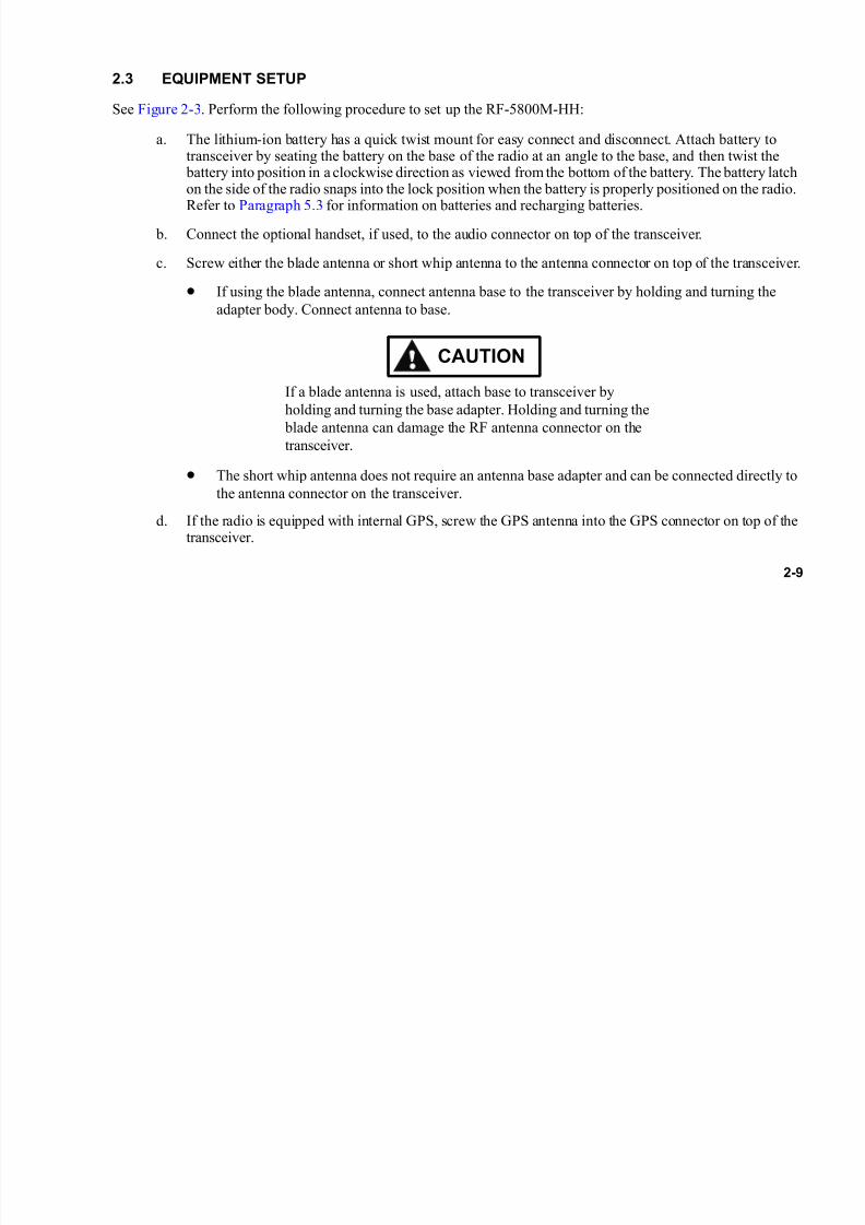
2.3 EQUIPMENT SETUP. . . . . . . . . . . . . . . . . . . . . . . . . . . . . . . . . . . . . . . . . . . 2-9
2.4 EQUIPMENT TEARDOWN . . . . . . . . . . . . . . . . . . . . . . . . . . . . . . . . . . . . . . 2-10
7/21/2019 RF-5800M HH Ops Manual
http://slidepdf.com/reader/full/rf-5800m-hh-ops-manual 8/199
ii
TABLE OF CONTENTS – Continued
Paragraph Page
CHAPTER 3 – RADIO OPERATION
3.1 INTRODUCTION . . . . . . . . . . . . . . . . . . . . . . . . . . . . . . . . . . . . . . . . . . . . . . 3-1
3.2 OPERATION TASK SUMMARY. . . . . . . . . . . . . . . . . . . . . . . . . . . . . . . . . . . 3-1
3.3 CONTROLS, INDICATORS, AND CONNECTORS. . . . . . . . . . . . . . . . . . . . 3-2
3.3.1 Number Entry. . . . . . . . . . . . . . . . . . . . . . . . . . . . . . . . . . . . . . . . . . . . . . . . . 3-8
3.4 RADIO POWER-ON. . . . . . . . . . . . . . . . . . . . . . . . . . . . . . . . . . . . . . . . . . . . 3-9
3.5 RADIO LOCK. . . . . . . . . . . . . . . . . . . . . . . . . . . . . . . . . . . . . . . . . . . . . . . . . 3-9
3.5.1 Locking the Radio . . . . . . . . . . . . . . . . . . . . . . . . . . . . . . . . . . . . . . . . . . . . . 3-9
3.5.2 Unlocking the Radio. . . . . . . . . . . . . . . . . . . . . . . . . . . . . . . . . . . . . . . . . . . . 3-10
3.6 KEYPAD LOCK . . . . . . . . . . . . . . . . . . . . . . . . . . . . . . . . . . . . . . . . . . . . . . . 3-10
3.6.1 Locking the Keypad . . . . . . . . . . . . . . . . . . . . . . . . . . . . . . . . . . . . . . . . . . . . 3-10
3.6.2 Unlocking the Keypad . . . . . . . . . . . . . . . . . . . . . . . . . . . . . . . . . . . . . . . . . . 3-11
3.7 INITIAL TESTS. . . . . . . . . . . . . . . . . . . . . . . . . . . . . . . . . . . . . . . . . . . . . . . . 3-11
3.7.1 Automatic Test . . . . . . . . . . . . . . . . . . . . . . . . . . . . . . . . . . . . . . . . . . . . . . . . 3-12
3.7.2 Optional Manual Tests . . . . . . . . . . . . . . . . . . . . . . . . . . . . . . . . . . . . . . . . . . 3-12
3.7.3 Battery Test . . . . . . . . . . . . . . . . . . . . . . . . . . . . . . . . . . . . . . . . . . . . . . . . . . 3-143.7.4 Optional Version Tests . . . . . . . . . . . . . . . . . . . . . . . . . . . . . . . . . . . . . . . . . . 3-15
3.8 LT BUTTON OPERATION . . . . . . . . . . . . . . . . . . . . . . . . . . . . . . . . . . . . . . . 3-15
3.9 BEFORE OPERATING THE RF-5800M-HH . . . . . . . . . . . . . . . . . . . . . . . . . 3-16
3.9.1 Voice/Data and Cipher Text Compatibility . . . . . . . . . . . . . . . . . . . . . . . . . . . 3-17
3.9.2 Cipher Text Compatibility . . . . . . . . . . . . . . . . . . . . . . . . . . . . . . . . . . . . . . . . 3-18
3.10 SELECTING PT OR CT. . . . . . . . . . . . . . . . . . . . . . . . . . . . . . . . . . . . . . . . . 3-18
3.11 BASIC OPERATION FROM NET PRESET. . . . . . . . . . . . . . . . . . . . . . . . . . 3-18
7/21/2019 RF-5800M HH Ops Manual
http://slidepdf.com/reader/full/rf-5800m-hh-ops-manual 9/199
ii
TABLE OF CONTENTS – Continued
Paragraph Page
CHAPTER 3 – RADIO OPERATION - CONTINUED
3.11.1 Overview - Contents of a Net Preset . . . . . . . . . . . . . . . . . . . . . . . . . . . . . . . 3-19
3.11.2 LCD Display - Preset Screens . . . . . . . . . . . . . . . . . . . . . . . . . . . . . . . . . . . . 3-19
3.11.3 Select a Net Preset . . . . . . . . . . . . . . . . . . . . . . . . . . . . . . . . . . . . . . . . . . . . 3-23
3.11.4 Data/Voice (D/V) Settings. . . . . . . . . . . . . . . . . . . . . . . . . . . . . . . . . . . . . . . . 3-23
3.11.5 Squelch (SQL) Settings . . . . . . . . . . . . . . . . . . . . . . . . . . . . . . . . . . . . . . . . . 3-23
3.11.6 Radio Programming Versus Temporary Overrides. . . . . . . . . . . . . . . . . . . . . 3-24
3.12 ZERO OPERATION . . . . . . . . . . . . . . . . . . . . . . . . . . . . . . . . . . . . . . . . . . . . 3-25
3.13 RADIO OPTIONS. . . . . . . . . . . . . . . . . . . . . . . . . . . . . . . . . . . . . . . . . . . . . . 3-27
3.13.1 SAVE . . . . . . . . . . . . . . . . . . . . . . . . . . . . . . . . . . . . . . . . . . . . . . . . . . . . . . . 3-28
3.13.2 COMSEC . . . . . . . . . . . . . . . . . . . . . . . . . . . . . . . . . . . . . . . . . . . . . . . . . . . . 3-28
3.13.3 Speaker (SPKR). . . . . . . . . . . . . . . . . . . . . . . . . . . . . . . . . . . . . . . . . . . . . . . 3-28
3.13.4 GPS . . . . . . . . . . . . . . . . . . . . . . . . . . . . . . . . . . . . . . . . . . . . . . . . . . . . . . . . 3-29
3.13.5 RADIO . . . . . . . . . . . . . . . . . . . . . . . . . . . . . . . . . . . . . . . . . . . . . . . . . . . . . . 3-29
3.13.6 SMS . . . . . . . . . . . . . . . . . . . . . . . . . . . . . . . . . . . . . . . . . . . . . . . . . . . . . . . . 3-29
3.13.7 POWER . . . . . . . . . . . . . . . . . . . . . . . . . . . . . . . . . . . . . . . . . . . . . . . . . . . . . 3-293.13.8 ALERTS . . . . . . . . . . . . . . . . . . . . . . . . . . . . . . . . . . . . . . . . . . . . . . . . . . . . . 3-30
3.13.9 HQTOD . . . . . . . . . . . . . . . . . . . . . . . . . . . . . . . . . . . . . . . . . . . . . . . . . . . . . 3-30
3.13.10 LOCKSETS (Hopping Only) . . . . . . . . . . . . . . . . . . . . . . . . . . . . . . . . . . . . . . 3-30
3.14 NET SCANNING . . . . . . . . . . . . . . . . . . . . . . . . . . . . . . . . . . . . . . . . . . . . . . 3-31
3.15 OPERATIONAL MODE MENU . . . . . . . . . . . . . . . . . . . . . . . . . . . . . . . . . . . 3-35
3.15.1 Remote Control . . . . . . . . . . . . . . . . . . . . . . . . . . . . . . . . . . . . . . . . . . . . . . . 3-36
3.15.2 Beacon Mode . . . . . . . . . . . . . . . . . . . . . . . . . . . . . . . . . . . . . . . . . . . . . . . . . 3-36

7/21/2019 RF-5800M HH Ops Manual
http://slidepdf.com/reader/full/rf-5800m-hh-ops-manual 10/199
iv
TABLE OF CONTENTS – Continued
Paragraph Page
CHAPTER 3 – RADIO OPERATION - CONTINUED
3.15.3 Retransmit Mode . . . . . . . . . . . . . . . . . . . . . . . . . . . . . . . . . . . . . . . . . . . . . . 3-37
3.15.3.1 Black Digital Retransmit Operation . . . . . . . . . . . . . . . . . . . . . . . . . . . . . . . . 3-38
3.15.3.2 Red Analog Retransmit Operation . . . . . . . . . . . . . . . . . . . . . . . . . . . . . . . . . 3-40
3.15.3.3 Repeater Retransmission Operation . . . . . . . . . . . . . . . . . . . . . . . . . . . . . . . 3-42
3.15.3.4 Hardware for Retransmission/Repeater Setup . . . . . . . . . . . . . . . . . . . . . . . 3-44
3.15.3.5 Frequency Separation . . . . . . . . . . . . . . . . . . . . . . . . . . . . . . . . . . . . . . . . . . 3-44
3.15.3.6 Retransmit Settings . . . . . . . . . . . . . . . . . . . . . . . . . . . . . . . . . . . . . . . . . . . . 3-46
3.15.4 Clone Mode . . . . . . . . . . . . . . . . . . . . . . . . . . . . . . . . . . . . . . . . . . . . . . . . . . 3-47
3.15.4.1 Receiving Wireless Cloning Information . . . . . . . . . . . . . . . . . . . . . . . . . . . . 3-47
3.15.4.2 Transmitting Wireless Cloning Information. . . . . . . . . . . . . . . . . . . . . . . . . . . 3-49
3.15.4.3 Verifying The Status Of A Wireless Cloning Transfer. . . . . . . . . . . . . . . . . . . 3-50
3.15.5 Keypad Lock . . . . . . . . . . . . . . . . . . . . . . . . . . . . . . . . . . . . . . . . . . . . . . . . . 3-50
3.15.6 Radio Lock . . . . . . . . . . . . . . . . . . . . . . . . . . . . . . . . . . . . . . . . . . . . . . . . . . . 3-50
3.15.7 Test Mode. . . . . . . . . . . . . . . . . . . . . . . . . . . . . . . . . . . . . . . . . . . . . . . . . . . . 3-50
3.15.8 VAA Mode . . . . . . . . . . . . . . . . . . . . . . . . . . . . . . . . . . . . . . . . . . . . . . . . . . . 3-50
CHAPTER 4 – RADIO PROGRAMMING
4.1 PROGRAMMING TASK SUMMARY . . . . . . . . . . . . . . . . . . . . . . . . . . . . . . . 4-1
4.2 ATTACHING A PC TO RADIO FOR VHF-UHF RPA PROGRAMMING . . . . 4-2
4.3 PROGRAMMING MENU TREE . . . . . . . . . . . . . . . . . . . . . . . . . . . . . . . . . . . 4-3
4.4 SECURITY MENU (SECUR) . . . . . . . . . . . . . . . . . . . . . . . . . . . . . . . . . . . . . 4-10
7/21/2019 RF-5800M HH Ops Manual
http://slidepdf.com/reader/full/rf-5800m-hh-ops-manual 11/199
v
TABLE OF CONTENTS – Continued
Paragraph Page
CHAPTER 4 – RADIO PROGRAMMING - CONTINUED
4.4.1 Level Access . . . . . . . . . . . . . . . . . . . . . . . . . . . . . . . . . . . . . . . . . . . . . . . . . 4-10
4.4.2 Password Programming . . . . . . . . . . . . . . . . . . . . . . . . . . . . . . . . . . . . . . . . . 4-11
4.4.3 BYPASS Programming. . . . . . . . . . . . . . . . . . . . . . . . . . . . . . . . . . . . . . . . . . 4-12
4.5 NORM MENU. . . . . . . . . . . . . . . . . . . . . . . . . . . . . . . . . . . . . . . . . . . . . . . . . 4-12
4.5.1 GENERAL Programming . . . . . . . . . . . . . . . . . . . . . . . . . . . . . . . . . . . . . . . . 4-12
4.5.1.1 NAME Programming . . . . . . . . . . . . . . . . . . . . . . . . . . . . . . . . . . . . . . . . . . . 4-13
4.5.1.2 ENCKEY Programming . . . . . . . . . . . . . . . . . . . . . . . . . . . . . . . . . . . . . . . . . 4-13
4.5.1.3 HOPSET Programming . . . . . . . . . . . . . . . . . . . . . . . . . . . . . . . . . . . . . . . . . 4-14
4.5.1.4 LOCKSET Programming . . . . . . . . . . . . . . . . . . . . . . . . . . . . . . . . . . . . . . . . 4-15
4.5.2 Net Programming . . . . . . . . . . . . . . . . . . . . . . . . . . . . . . . . . . . . . . . . . . . . . . 4-16
4.5.2.1 Net Programming Considerations . . . . . . . . . . . . . . . . . . . . . . . . . . . . . . . . . 4-16
4.5.2.2 Fixed Frequency Net Programming . . . . . . . . . . . . . . . . . . . . . . . . . . . . . . . . 4-17
4.5.2.3 Frequency Hopping Net Programming. . . . . . . . . . . . . . . . . . . . . . . . . . . . . . 4-19
4.6 SCAN MENU . . . . . . . . . . . . . . . . . . . . . . . . . . . . . . . . . . . . . . . . . . . . . . . . . 4-20
4.6.1 Scan List Programming . . . . . . . . . . . . . . . . . . . . . . . . . . . . . . . . . . . . . . . . . 4-214.6.2 PRIORITY Programming . . . . . . . . . . . . . . . . . . . . . . . . . . . . . . . . . . . . . . . . 4-21
4.6.2.1 CONFIG Programming. . . . . . . . . . . . . . . . . . . . . . . . . . . . . . . . . . . . . . . . . . 4-22
4.7 PORTS MENU . . . . . . . . . . . . . . . . . . . . . . . . . . . . . . . . . . . . . . . . . . . . . . . . 4-22
4.7.1 REMOTE Port Programming . . . . . . . . . . . . . . . . . . . . . . . . . . . . . . . . . . . . . 4-23
4.7.2 View Data Port Setting . . . . . . . . . . . . . . . . . . . . . . . . . . . . . . . . . . . . . . . . . . 4-23
4.8 CFIG MENU . . . . . . . . . . . . . . . . . . . . . . . . . . . . . . . . . . . . . . . . . . . . . . . . . . 4-24
4.8.1 GENERAL Settings . . . . . . . . . . . . . . . . . . . . . . . . . . . . . . . . . . . . . . . . . . . . 4-24

7/21/2019 RF-5800M HH Ops Manual
http://slidepdf.com/reader/full/rf-5800m-hh-ops-manual 12/199
vi
TABLE OF CONTENTS – Continued
Paragraph Page
CHAPTER 4 – RADIO PROGRAMMING - CONTINUED
4.8.2 Programming Beacon Settings . . . . . . . . . . . . . . . . . . . . . . . . . . . . . . . . . . . 4-25
4.8.3 Programming Clock Settings . . . . . . . . . . . . . . . . . . . . . . . . . . . . . . . . . . . . . 4-27
4.8.4 Programming External Device (EXT_DEV) Settings . . . . . . . . . . . . . . . . . . . 4-27
4.8.5 Programming RF-6010 Basestation Settings. . . . . . . . . . . . . . . . . . . . . . . . . 4-28
4.8.6 Programming Situational Awareness Settings . . . . . . . . . . . . . . . . . . . . . . . . 4-28
4.8.7 Programming Wireless IP Network Settings . . . . . . . . . . . . . . . . . . . . . . . . . 4-28
4.8.8 Programming Short Messaging Service Settings. . . . . . . . . . . . . . . . . . . . . . 4-28
4.8.9 Programming Falcon Watch™ Sensor Alert Settings . . . . . . . . . . . . . . . . . . 4-28
CHAPTER 5 – PREVENTIVE AND CORRECTIVE MAINTENANCE
5.1 PREVENTIVE MAINTENANCE . . . . . . . . . . . . . . . . . . . . . . . . . . . . . . . . . . . 5-1
5.2 CORRECTIVE MAINTENANCE . . . . . . . . . . . . . . . . . . . . . . . . . . . . . . . . . . 5-2
5.2.1 Troubleshooting Procedures . . . . . . . . . . . . . . . . . . . . . . . . . . . . . . . . . . . . . 5-3
5.2.1.1 BIT Faults. . . . . . . . . . . . . . . . . . . . . . . . . . . . . . . . . . . . . . . . . . . . . . . . . . . . 5-35.2.1.2 Non-BIT Faults. . . . . . . . . . . . . . . . . . . . . . . . . . . . . . . . . . . . . . . . . . . . . . . . 5-3
5.3 BATTERIES. . . . . . . . . . . . . . . . . . . . . . . . . . . . . . . . . . . . . . . . . . . . . . . . . . 5-6
5.3.1 Battery Life. . . . . . . . . . . . . . . . . . . . . . . . . . . . . . . . . . . . . . . . . . . . . . . . . . . 5-6
5.3.2 Recharging the Li-ION Battery Packs . . . . . . . . . . . . . . . . . . . . . . . . . . . . . . 5-7
5.3.3 Disposing of Li-ION Batteries. . . . . . . . . . . . . . . . . . . . . . . . . . . . . . . . . . . . . 5-8
5.3.4 Battery Storage and Maintenance . . . . . . . . . . . . . . . . . . . . . . . . . . . . . . . . . 5-9

7/21/2019 RF-5800M HH Ops Manual
http://slidepdf.com/reader/full/rf-5800m-hh-ops-manual 13/199
vi
TABLE OF CONTENTS – Continued
Paragraph Page
APPENDIX A
A.1 CHASSIS CONNECTOR PINOUT DATA . . . . . . . . . . . . . . . . . . . . . . . . . . . A-1
APPENDIX B - ADVANCED FEATURES
B.1 INTRODUCTION . . . . . . . . . . . . . . . . . . . . . . . . . . . . . . . . . . . . . . . . . . . . . . B-1
B.2 RF-6010 BASESTATION . . . . . . . . . . . . . . . . . . . . . . . . . . . . . . . . . . . . . . . . B-5
B.3 DIRECTED CALLING. . . . . . . . . . . . . . . . . . . . . . . . . . . . . . . . . . . . . . . . . . . B-6
B.3.1 Description . . . . . . . . . . . . . . . . . . . . . . . . . . . . . . . . . . . . . . . . . . . . . . . . . . . B-6
B.3.2 Initiating a Directed Call Using a Radio ID . . . . . . . . . . . . . . . . . . . . . . . . . . . B-7
B.3.2.1 Terminating a Directed Call . . . . . . . . . . . . . . . . . . . . . . . . . . . . . . . . . . . . . . B-8
B.3.2.2 Breaking into a Directed Call . . . . . . . . . . . . . . . . . . . . . . . . . . . . . . . . . . . . . B-8
B.3.2.3 Busy State . . . . . . . . . . . . . . . . . . . . . . . . . . . . . . . . . . . . . . . . . . . . . . . . . . . B-9
B.3.2.4 Radio Call Inactivity Timer . . . . . . . . . . . . . . . . . . . . . . . . . . . . . . . . . . . . . . . B-9
B.3.3 Directed Calling Programming . . . . . . . . . . . . . . . . . . . . . . . . . . . . . . . . . . . . B-9
B.3.3.1 Net Programming . . . . . . . . . . . . . . . . . . . . . . . . . . . . . . . . . . . . . . . . . . . . . . B-9B.3.4 Error Messages and Corrective Actions. . . . . . . . . . . . . . . . . . . . . . . . . . . . . B-11
B.4 SITUATIONAL AWARENESS (SA) . . . . . . . . . . . . . . . . . . . . . . . . . . . . . . . . B-12
B.4.1 Description . . . . . . . . . . . . . . . . . . . . . . . . . . . . . . . . . . . . . . . . . . . . . . . . . . . B-12
B.4.2 SA Features . . . . . . . . . . . . . . . . . . . . . . . . . . . . . . . . . . . . . . . . . . . . . . . . . . B-13
B.4.3 SA Operation . . . . . . . . . . . . . . . . . . . . . . . . . . . . . . . . . . . . . . . . . . . . . . . . . B-14
B.4.3.1 SA Configuration - Internal GPS . . . . . . . . . . . . . . . . . . . . . . . . . . . . . . . . . . B-14
B.4.3.2 SA Configuration - External GPS . . . . . . . . . . . . . . . . . . . . . . . . . . . . . . . . . . B-24
7/21/2019 RF-5800M HH Ops Manual
http://slidepdf.com/reader/full/rf-5800m-hh-ops-manual 14/199
viii
TABLE OF CONTENTS – Continued
Paragraph Page
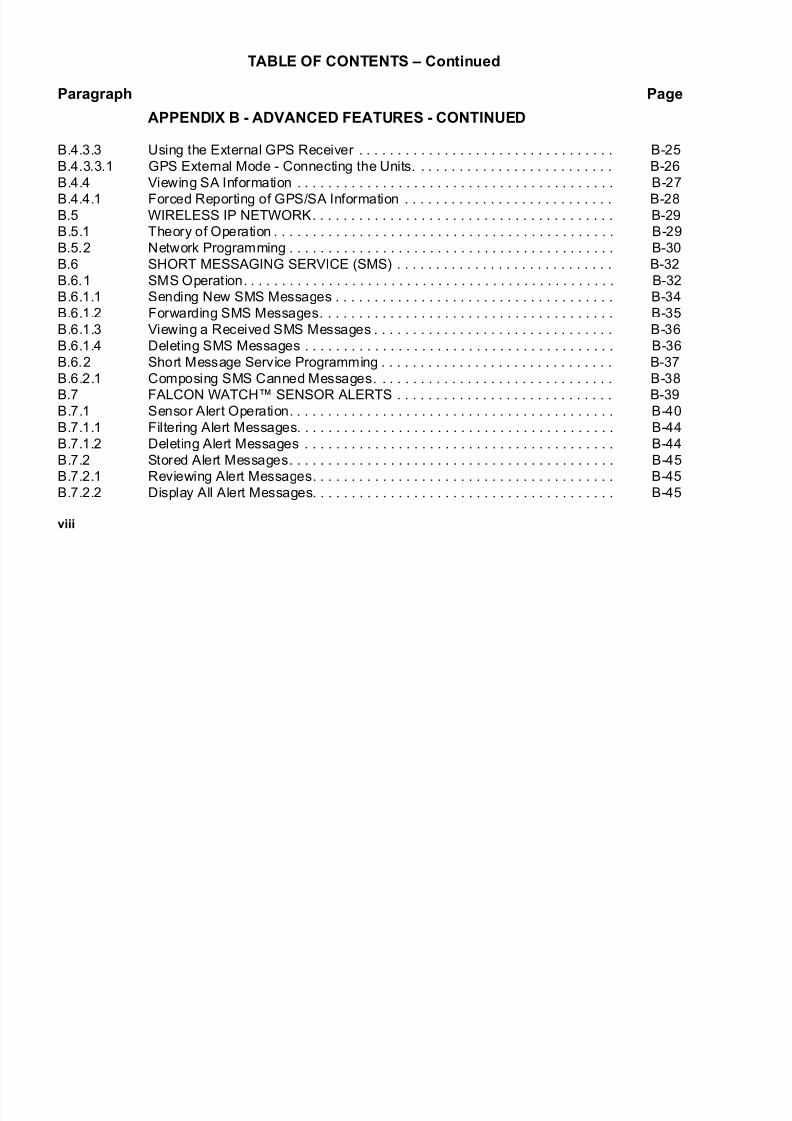
APPENDIX B - ADVANCED FEATURES - CONTINUED
B.4.3.3 Using the External GPS Receiver . . . . . . . . . . . . . . . . . . . . . . . . . . . . . . . . . B-25
B.4.3.3.1 GPS External Mode - Connecting the Units. . . . . . . . . . . . . . . . . . . . . . . . . . B-26
B.4.4 Viewing SA Information . . . . . . . . . . . . . . . . . . . . . . . . . . . . . . . . . . . . . . . . . B-27
B.4.4.1 Forced Reporting of GPS/SA Information . . . . . . . . . . . . . . . . . . . . . . . . . . . B-28
B.5 WIRELESS IP NETWORK. . . . . . . . . . . . . . . . . . . . . . . . . . . . . . . . . . . . . . . B-29
B.5.1 Theory of Operation . . . . . . . . . . . . . . . . . . . . . . . . . . . . . . . . . . . . . . . . . . . . B-29
B.5.2 Network Programming . . . . . . . . . . . . . . . . . . . . . . . . . . . . . . . . . . . . . . . . . . B-30
B.6 SHORT MESSAGING SERVICE (SMS) . . . . . . . . . . . . . . . . . . . . . . . . . . . . B-32
B.6.1 SMS Operation. . . . . . . . . . . . . . . . . . . . . . . . . . . . . . . . . . . . . . . . . . . . . . . . B-32
B.6.1.1 Sending New SMS Messages . . . . . . . . . . . . . . . . . . . . . . . . . . . . . . . . . . . . B-34
B.6.1.2 Forwarding SMS Messages. . . . . . . . . . . . . . . . . . . . . . . . . . . . . . . . . . . . . . B-35
B.6.1.3 Viewing a Received SMS Messages . . . . . . . . . . . . . . . . . . . . . . . . . . . . . . . B-36
B.6.1.4 Deleting SMS Messages . . . . . . . . . . . . . . . . . . . . . . . . . . . . . . . . . . . . . . . . B-36
B.6.2 Short Message Service Programming . . . . . . . . . . . . . . . . . . . . . . . . . . . . . . B-37
B.6.2.1 Composing SMS Canned Messages. . . . . . . . . . . . . . . . . . . . . . . . . . . . . . . B-38B.7 FALCON WATCH™ SENSOR ALERTS . . . . . . . . . . . . . . . . . . . . . . . . . . . . B-39
B.7.1 Sensor Alert Operation. . . . . . . . . . . . . . . . . . . . . . . . . . . . . . . . . . . . . . . . . . B-40
B.7.1.1 Filtering Alert Messages. . . . . . . . . . . . . . . . . . . . . . . . . . . . . . . . . . . . . . . . . B-44
B.7.1.2 Deleting Alert Messages . . . . . . . . . . . . . . . . . . . . . . . . . . . . . . . . . . . . . . . . B-44
B.7.2 Stored Alert Messages. . . . . . . . . . . . . . . . . . . . . . . . . . . . . . . . . . . . . . . . . . B-45
B.7.2.1 Reviewing Alert Messages. . . . . . . . . . . . . . . . . . . . . . . . . . . . . . . . . . . . . . . B-45
B.7.2.2 Display All Alert Messages. . . . . . . . . . . . . . . . . . . . . . . . . . . . . . . . . . . . . . . B-45

7/21/2019 RF-5800M HH Ops Manual
http://slidepdf.com/reader/full/rf-5800m-hh-ops-manual 15/199
ix
TABLE OF CONTENTS – Continued
Paragraph Page
APPENDIX B - ADVANCED FEATURES - CONTINUED
B.7.2.3 Deleting All Alert Messages . . . . . . . . . . . . . . . . . . . . . . . . . . . . . . . . . . . . . . B-46
B.7.3 Sensor Alert Programming. . . . . . . . . . . . . . . . . . . . . . . . . . . . . . . . . . . . . . . B-46
B.7.4 Tamper Alert Reports . . . . . . . . . . . . . . . . . . . . . . . . . . . . . . . . . . . . . . . . . . . B-47
B.7.5 Low Battery Alert . . . . . . . . . . . . . . . . . . . . . . . . . . . . . . . . . . . . . . . . . . . . . . B-47
GLOSSARY
INDEX
7/21/2019 RF-5800M HH Ops Manual
http://slidepdf.com/reader/full/rf-5800m-hh-ops-manual 16/199
x
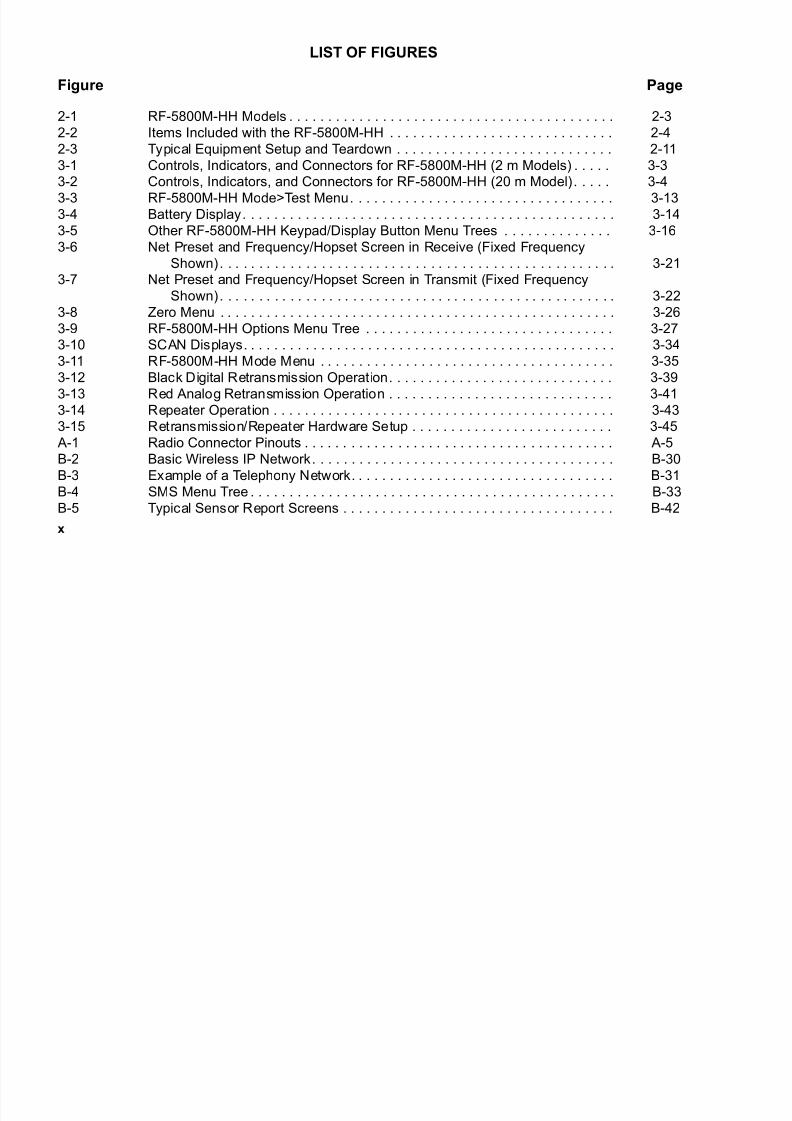
LIST OF FIGURES
Figure Page
2-1 RF-5800M-HH Models . . . . . . . . . . . . . . . . . . . . . . . . . . . . . . . . . . . . . . . . . . 2-3
2-2 Items Included with the RF-5800M-HH . . . . . . . . . . . . . . . . . . . . . . . . . . . . . 2-4
2-3 Typical Equipment Setup and Teardown . . . . . . . . . . . . . . . . . . . . . . . . . . . . 2-11
3-1 Controls, Indicators, and Connectors for RF-5800M-HH (2 m Models) . . . . . 3-3
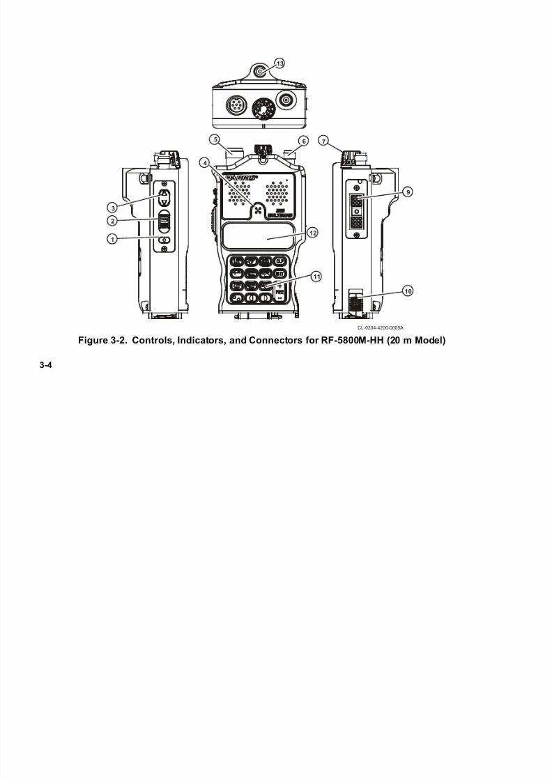
3-2 Controls, Indicators, and Connectors for RF-5800M-HH (20 m Model). . . . . 3-4
3-3 RF-5800M-HH Mode>Test Menu. . . . . . . . . . . . . . . . . . . . . . . . . . . . . . . . . . 3-13
3-4 Battery Display. . . . . . . . . . . . . . . . . . . . . . . . . . . . . . . . . . . . . . . . . . . . . . . . 3-14
3-5 Other RF-5800M-HH Keypad/Display Button Menu Trees . . . . . . . . . . . . . . 3-16
3-6 Net Preset and Frequency/Hopset Screen in Receive (Fixed Frequency
Shown). . . . . . . . . . . . . . . . . . . . . . . . . . . . . . . . . . . . . . . . . . . . . . . . . . . 3-21
3-7 Net Preset and Frequency/Hopset Screen in Transmit (Fixed Frequency
Shown). . . . . . . . . . . . . . . . . . . . . . . . . . . . . . . . . . . . . . . . . . . . . . . . . . . 3-22
3-8 Zero Menu . . . . . . . . . . . . . . . . . . . . . . . . . . . . . . . . . . . . . . . . . . . . . . . . . . . 3-26
3-9 RF-5800M-HH Options Menu Tree . . . . . . . . . . . . . . . . . . . . . . . . . . . . . . . . 3-27
3-10 SCAN Displays. . . . . . . . . . . . . . . . . . . . . . . . . . . . . . . . . . . . . . . . . . . . . . . . 3-34
3-11 RF-5800M-HH Mode Menu . . . . . . . . . . . . . . . . . . . . . . . . . . . . . . . . . . . . . . 3-35
3-12 Black Digital Retransmission Operation. . . . . . . . . . . . . . . . . . . . . . . . . . . . . 3-393-13 Red Analog Retransmission Operation . . . . . . . . . . . . . . . . . . . . . . . . . . . . . 3-41
3-14 Repeater Operation . . . . . . . . . . . . . . . . . . . . . . . . . . . . . . . . . . . . . . . . . . . . 3-43
3-15 Retransmission/Repeater Hardware Setup . . . . . . . . . . . . . . . . . . . . . . . . . . 3-45
A-1 Radio Connector Pinouts . . . . . . . . . . . . . . . . . . . . . . . . . . . . . . . . . . . . . . . . A-5
B-2 Basic Wireless IP Network. . . . . . . . . . . . . . . . . . . . . . . . . . . . . . . . . . . . . . . B-30
B-3 Example of a Telephony Network. . . . . . . . . . . . . . . . . . . . . . . . . . . . . . . . . . B-31
B-4 SMS Menu Tree . . . . . . . . . . . . . . . . . . . . . . . . . . . . . . . . . . . . . . . . . . . . . . . B-33
B-5 Typical Sensor Report Screens . . . . . . . . . . . . . . . . . . . . . . . . . . . . . . . . . . . B-42
7/21/2019 RF-5800M HH Ops Manual
http://slidepdf.com/reader/full/rf-5800m-hh-ops-manual 17/199
x
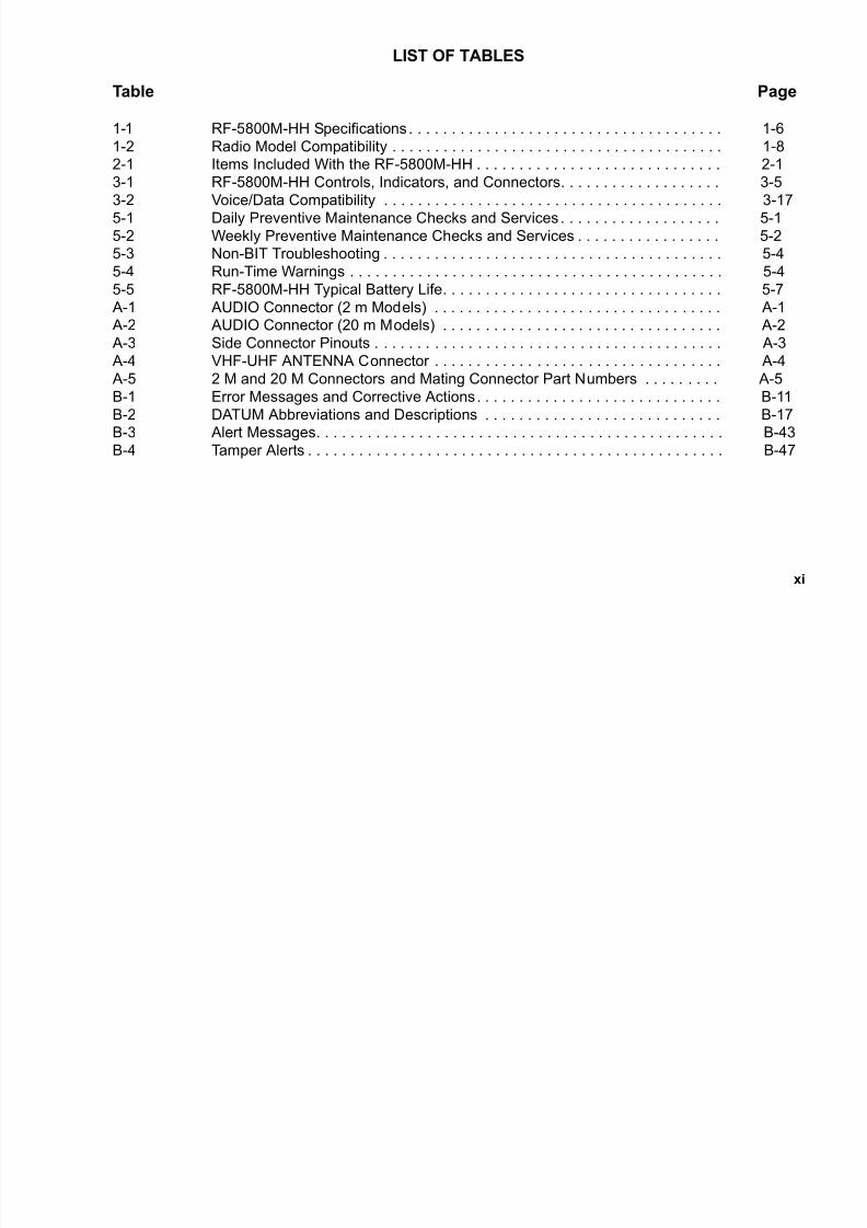
LIST OF TABLES
Table Page
1-1 RF-5800M-HH Specifications . . . . . . . . . . . . . . . . . . . . . . . . . . . . . . . . . . . . . 1-6
1-2 Radio Model Compatibility . . . . . . . . . . . . . . . . . . . . . . . . . . . . . . . . . . . . . . . 1-8
2-1 Items Included With the RF-5800M-HH . . . . . . . . . . . . . . . . . . . . . . . . . . . . . 2-1
3-1 RF-5800M-HH Controls, Indicators, and Connectors. . . . . . . . . . . . . . . . . . . 3-5
3-2 Voice/Data Compatibility . . . . . . . . . . . . . . . . . . . . . . . . . . . . . . . . . . . . . . . . 3-17
5-1 Daily Preventive Maintenance Checks and Services . . . . . . . . . . . . . . . . . . . 5-1
5-2 Weekly Preventive Maintenance Checks and Services . . . . . . . . . . . . . . . . . 5-2
5-3 Non-BIT Troubleshooting . . . . . . . . . . . . . . . . . . . . . . . . . . . . . . . . . . . . . . . . 5-4
5-4 Run-Time Warnings . . . . . . . . . . . . . . . . . . . . . . . . . . . . . . . . . . . . . . . . . . . . 5-4
5-5 RF-5800M-HH Typical Battery Life. . . . . . . . . . . . . . . . . . . . . . . . . . . . . . . . . 5-7
A-1 AUDIO Connector (2 m Models) . . . . . . . . . . . . . . . . . . . . . . . . . . . . . . . . . . A-1
A-2 AUDIO Connector (20 m Models) . . . . . . . . . . . . . . . . . . . . . . . . . . . . . . . . . A-2
A-3 Side Connector Pinouts . . . . . . . . . . . . . . . . . . . . . . . . . . . . . . . . . . . . . . . . . A-3
A-4 VHF-UHF ANTENNA Connector . . . . . . . . . . . . . . . . . . . . . . . . . . . . . . . . . . A-4
A-5 2 M and 20 M Connectors and Mating Connector Part Numbers . . . . . . . . . A-5
B-1 Error Messages and Corrective Actions. . . . . . . . . . . . . . . . . . . . . . . . . . . . . B-11
B-2 DATUM Abbreviations and Descriptions . . . . . . . . . . . . . . . . . . . . . . . . . . . . B-17B-3 Alert Messages. . . . . . . . . . . . . . . . . . . . . . . . . . . . . . . . . . . . . . . . . . . . . . . . B-43
B-4 Tamper Alerts . . . . . . . . . . . . . . . . . . . . . . . . . . . . . . . . . . . . . . . . . . . . . . . . . B-47

7/21/2019 RF-5800M HH Ops Manual
http://slidepdf.com/reader/full/rf-5800m-hh-ops-manual 18/199
xii
This page intentionally left blank.

7/21/2019 RF-5800M HH Ops Manual
http://slidepdf.com/reader/full/rf-5800m-hh-ops-manual 19/199
1-1
CHAPTER 1
EQUIPMENT DESCRIPTION
1.1 SAFETY PRECAUTIONS
All safety precautions necessary for the protection of personnel and equipment are cross-referenced in the following
list. The WARNING or CAUTION is referenced to the paragraph number where it is used in the manual, and a briefsubject phrase indicating the content is provided. Read these items in their entirety before performing the referenced
procedure.
• WARNING - Paragraph 2.2.1 - Do not crush, disassemble, reverse polarity incinerate, or mutilate the
lithium-ion battery.
• WARNING - Paragraph 2.2.1 - If the battery becomes hot, a hissing sound is heard, and an irritating smell
occurs; move the equipment to a well-ventilated area if possible.
• WARNING - Paragraph 2.2.1 - Use only battery chargers approved by Harris, and never modify the battery
or charger.
• CAUTION - Paragraph 2.2.1 - Acid contaminates lithium-ion batteries.
• CAUTION - Paragraph 2.3 - If using the blade antenna, tighten onto radio by turning the base adapter to
avoid damage to Radio Frequency (RF) antenna connector on the transceiver.
• CAUTION - Paragraph 2.4 - If using the blade antenna, loosen from the radio by turning the base adapter
to avoid damage to Radio Frequency (RF) antenna connector on the transceiver.
• WARNING - Paragraph 3.7 - To avoid hearing damage, check the volume level before using the radio.
7/21/2019 RF-5800M HH Ops Manual
http://slidepdf.com/reader/full/rf-5800m-hh-ops-manual 20/199
1-2
• WARNING - Paragraph 3.15.3 - Avoid contact with antennas in retransmit mode to prevent electrical shock
and RF burns.
• WARNING - Paragraph 5.3.2 - Do not attempt to recharge a disposable lithium battery.
• WARNING - Paragraph 5.3.3 - Do not dispose of lithium-ion batteries in uncontrolled trash.
1.2 PURPOSE OF THIS MANUAL
This operation manual provides the user with operating instructions for the RF-5800M-HH Export Multiband
Handheld Radio (often referred to throughout this manual as RF-5800M-HH), as well as technical information
required to support Level I (operator) Maintenance.
1.3 EQUIPMENT DESCRIPTION
The RF-5800M-HH is an advanced mulitband handheld radio which provides reliable tactical communications
performance in a small, lightweight package that maximizes user mobility. The RF-5800M-HH can quickly shift
between Line-of-Sight (LOS), ground-to-ground, and Ultra High Frequency (UHF) ground-to-air communications
in the frequency band of 30 MHz to 512 MHz. Supported modulation modes are Frequency Modulation (FM),
Amplitude Modulation (AM), 16 kbps Wideband Frequency Shift Keying (WBFSK), and Amplitude Shift Keying
(ASK) data. Communications can take place with handheld, manpack, mobile, and fixed-site stations in either
encrypted or unencrypted modes. The RF-5800M-HH allows selectable transmit power levels, and operates from a
single, rechargeable Lithium-Ion (Li-ION) handheld battery.
NOTE
The radio supports Continuously Variable Slope Delta
(CVSD) voice and data communications only with other
Harris Falcon II radios that use this mode.
7/21/2019 RF-5800M HH Ops Manual
http://slidepdf.com/reader/full/rf-5800m-hh-ops-manual 21/199
1-3
A menu driven interface is used to access the radio operation and features. Up to 25 user-defined net presets provide
complete frequency programming and other radio parameters including radio operating mode, Communications
Security (COMSEC) keys, and Transmission Security (TRANSEC) keys. Quick selection of five nets can be done
using the knob on top of the radio. The radio also supports remote control operation from a separate terminal.
The RF-5800M-HH supports two types of radio net structures. A fixed frequency net is made up of a frequency,
mode of operation, squelch setting, transmit power level, and a net name. A frequency hopping net is similar to a
fixed frequency net except that the radio continuously changes the operating frequency, which must be synchronized
between the transmitter and receiver.
Additionally, the RF-5800M-HH provides Built-In Test Equipment (BITE) for radio operational test and battery
checks, as well as a hold-up battery circuit to maintain programmed information when powered off.
The RF-5800M-HH is available in several model configurations including: with or without Global Positioning
System (GPS), green or black finish, Harris Citadel I®
or Citadel II®
encryption for secure voice and data, and 2
meter (m) or 20 meter (m) submersible ratings.
NOTE
Whenever 2 m or 20 m is discussed in this manual, it is
referring to the salt water submersion rating in meters (not
wavelength).

7/21/2019 RF-5800M HH Ops Manual
http://slidepdf.com/reader/full/rf-5800m-hh-ops-manual 22/199
1-4
1.4 FEATURES
The RF-5800M-HH offers the following features:
• Fixed frequency and Quicklook 1A frequency hopping operation
• Optional Havequick frequency hopping
• Harris Citadel I®
or Citadel II®
encryption for secure voice and data operation
• Wireless cloning of radio configuration
• Net Scanning mode
• Situational Awareness position reporting
• Directed Calling
• Wireless Internet Protocol (IP)
• Short Messaging Service (SMS)
• Falcon Watch™ Sensor Alert Messaging
• DC Antenna Bias menu to support the RF-3162-AT001 VHF-UHF Dipole antenna
• Automatic whisper operation
• Cross-band and cross-mode retransmit operation
• Search and Rescue (SAR) beacon
• Operation with optional RF-5800M-V520 Vehicle Adapter Amplifier (VAA)
• Operation with optional RF-5800M-V500 Vehicle Adapter Amplifier (VAA)

7/21/2019 RF-5800M HH Ops Manual
http://slidepdf.com/reader/full/rf-5800m-hh-ops-manual 23/199
1-5
• Radio lock entered from front panel for RF-5800M-HH, available in both 2 meter (m) or 20 meter (m) model
configurations
• Direct Point-to-Point Protocol (PPP) network connection to Harris RF-6010 for both telephony and IP data
transfer
• RF-5800M-HH supports telephony calls when connected to a RF-6010 Basestation
• Jerk and Run cable sense functionality for vehicle mounted RF-5800M-V520 VAA
1.5 CONFIGURATIONS
The RF-5800M-HH radio is available in the following configurations:
• RF-5800M-HH001 Multiband radio, no internal GPS, green finish
• RF-5800M-HH002 Multiband radio, 20 meter submersible, no internal GPS, green finish
• RF-5800M-HH004 Multiband radio, no internal GPS, green finish
• RF-5800M-HH011 Multiband radio, no internal GPS, black finish
• RF-5800M-HH101 Multiband radio, with internal GPS, green finish
• RF-5800M-HH104 Multiband radio, with GPS, green finish
• RF-5800M-HH111 Multiband radio, with internal GPS, black finish
• RF-5800M-HH114 Multiband radio, with GPS, black finish
• RF-5800M-HH115 Multiband radio, 20 meter submersible, with GPS, black finish
7/21/2019 RF-5800M HH Ops Manual
http://slidepdf.com/reader/full/rf-5800m-hh-ops-manual 24/199
1-6
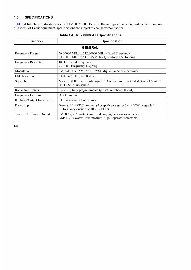
1.6 SPECIFICATIONS
Table 1-1 lists the specifications for the RF-5800M-HH. Because Harris engineers continuously strive to improve
all aspects of Harris equipment, specifications are subject to change without notice.
Table 1-1. RF-5800M-HH Specifications
Function Specification
GENERAL
Frequency Range 30.00000 MHz to 512.00000 MHz - Fixed Frequency30.00000 MHz to 511.975 MHz - Quicklook 1A Hopping
Frequency Resolution 10 Hz - Fixed Frequency25 kHz - Frequency Hopping
Modulation FM, WBFSK, AM, ASK, CVSD digital voice or clear voice
FM Deviation 5 kHz, 6.5 kHz, and 8 kHz
Squelch Noise, 150 Hz tone, digital squelch, Continuous Tone Coded Squelch System(CTCSS), or no squelch
Radio Net Presets Up to 25, fully programmable (presets numbered 0 - 24)
Frequency Hopping Quicklook 1A
RF Input/Output Impedance 50 ohms nominal, unbalanced
Power Input Battery, 10.8 VDC nominal (Acceptable range: 9.6 - 14 VDC; degraded performance outside of 10 - 13 VDC)
Transmitter Power Output FM: 0.25, 2, 5 watts; (low, medium, high - operator selectable)AM: 1, 2, 5 watts; (low, medium, high - operator selectable)
7/21/2019 RF-5800M HH Ops Manual
http://slidepdf.com/reader/full/rf-5800m-hh-ops-manual 25/199
1-7
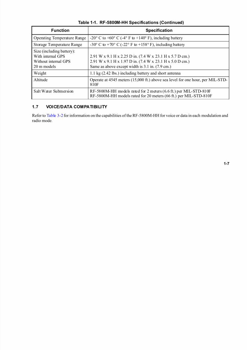
1.7 VOICE/DATA COMPATIBILITY
Refer to Table 3-2 for information on the capabilities of the RF-5800M-HH for voice or data in each modulation and
radio mode.
Operating Temperature Range -20° C to +60° C (-4° F to +140° F), including battery
Storage Temperature Range -30° C to +70° C (-22° F to +158° F), including battery
Size (including battery):
With internal GPS
Without internal GPS
20 m models
2.91 W x 9.1 H x 2.25 D in. (7.4 W x 23.1 H x 5.7 D cm.)
2.91 W x 9.1 H x 1.97 D in. (7.4 W x 23.1 H x 5.0 D cm.)
Same as above except width is 3.1 in. (7.9 cm.)
Weight 1.1 kg (2.42 lbs.) including battery and short antenna
Altitude Operate at 4545 meters (15,000 ft.) above sea level for one hour, per MIL-STD-810F
Salt Water Submersion RF-5800M-HH models rated for 2 meters (6.6 ft.) per MIL-STD-810FRF-5800M-HH models rated for 20 meters (66 ft.) per MIL-STD-810F
Table 1-1. RF-5800M-HH Specifications (Continued)
Function Specification

7/21/2019 RF-5800M HH Ops Manual
http://slidepdf.com/reader/full/rf-5800m-hh-ops-manual 26/199
1-8
1.8 COMPATIBILITY
Successful communications depends on using the correct encryption type and compatible radios. Table 1-2 provides
a list of compatible Harris radio models and radio modulation types and modes.
The RF-5800M-HH is interoperable in non-secure, fixed-frequency modes with other UHF and Very High
Frequency (VHF) radio systems. When communicating with older radio equipment, several net compatibility issues
must be considered when planning the net:
• Frequency - Older radio equipment does not support 10 Hz frequency resolution of the RF-5800M-HH in
fixed mode. When introducing older radio equipment to the net, only use frequencies that ALL radios can
support.
• Data/Voice Mode - Older radio equipment may not support data or digital voice operating modes. When
introducing older radio equipment to the net, only utilize operating modes that ALL radios can support.
• Squelch - Older radio equipment does not support digital squelch. When introducing older radio equipment
to the net, only utilize squelch types that ALL radios can support.
Table 1-2. Radio Model Compatibility
Radio Model
Encryption Modulation/Mode
Citadel** Voice
CVSD
VoiceData Frequency
HoppingFM AM FSK ASK FSK ASK
RF-5800M-HH
RF-5800U-HH * * * * * * *
RF-5800U-MP * * * * * * *

7/21/2019 RF-5800M HH Ops Manual
http://slidepdf.com/reader/full/rf-5800m-hh-ops-manual 27/199
1-9
= Compatible * = Compatible when using compatible frequencies
**RF-5800M-HH radios provide support for both Harris Citadel I®
and Harris Citadel II®
encryption and
Citadel II®
is backwards compatible with Citadel I®
.
1.9 COMPATIBLE CABLES AND CONNECTORS
Several cables are available for connecting external equipment to the RF-5800M-HH. Refer to Paragraph 2.1.1 for
a list of Harris cables.
Refer to Paragraph A.1 for connector pinout information. For mating connector part numbers, refer to Table A-5.
RF-5800M-MP RF-5800V-HH * * * *
RF-5800V-MP * * * *
Table 1-2. Radio Model Compatibility (Continued)
Radio Model
Encryption Modulation/Mode
Citadel** Voice
CVSD
VoiceData Frequency
HoppingFM AM FSK ASK FSK ASK

7/21/2019 RF-5800M HH Ops Manual
http://slidepdf.com/reader/full/rf-5800m-hh-ops-manual 28/199
1-10
This page intentionally left blank.
7/21/2019 RF-5800M HH Ops Manual
http://slidepdf.com/reader/full/rf-5800m-hh-ops-manual 29/199
2-1
CHAPTER 2
SETUP AND TEARDOWN
NOTE
In applications where the RF-5800M-HH is installed in a radio
system that includes other equipment, the system level
documentation takes precedence.
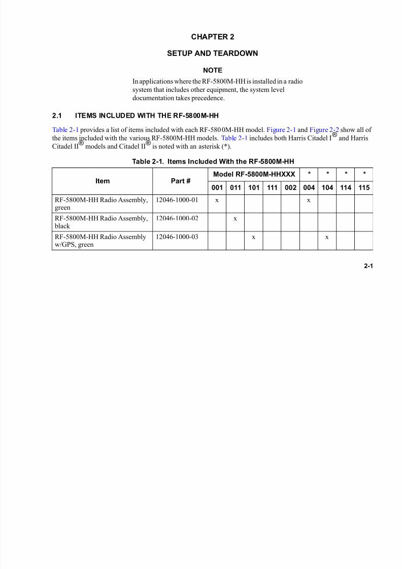
2.1 ITEMS INCLUDED WITH THE RF-5800M-HH
Table 2-1 provides a list of items included with each RF-5800M-HH model. Figure 2-1 and Figure 2-2 show all of
the items included with the various RF-5800M-HH models. Table 2-1 includes both Harris Citadel I®
and Harris
Citadel II®
models and Citadel II®
is noted with an asterisk (*).
Table 2-1. Items Included With the RF-5800M-HH
Item Part #Model RF-5800M-HHXXX * * * *
001 011 101 111 002 004 104 114 115
RF-5800M-HH Radio Assembly,green
12046-1000-01 x x
RF-5800M-HH Radio Assembly, black
12046-1000-02 x
RF-5800M-HH Radio Assemblyw/GPS, green
12046-1000-03 x x

7/21/2019 RF-5800M HH Ops Manual
http://slidepdf.com/reader/full/rf-5800m-hh-ops-manual 30/199
2-2
RF-5800M-HH Radio Assemblyw/GPS, black
12046-1000-08 x x
RF-5800M-HH Radio Assembly20 m
12046-6500-01 x x
MB-HH Short Whip Antenna 12041-2700-01 x x x x
MB-HH Short Whip Antenna, 20m submersible
12046-2700-01 x
MB-HH Blade Antenna 12011-2700-01 x x x x x x x x x
Rechargeable Lithium-Ion (Li-ION) Battery, Green
12041-2100-02 x x x x x
Rechargeable Lithium-Ion (Li-ION) Battery, Black
12041-2100-01 x x x x
Operator Card 10515-0234-
4100
x x x x x x x x x
MB-HH GPS Antenna 12041-6550-01 x x x x x
Table 2-1. Items Included With the RF-5800M-HH (Continued)
Item Part #Model RF-5800M-HHXXX * * * *
001 011 101 111 002 004 104 114 115
7/21/2019 RF-5800M HH Ops Manual
http://slidepdf.com/reader/full/rf-5800m-hh-ops-manual 31/199
2-3
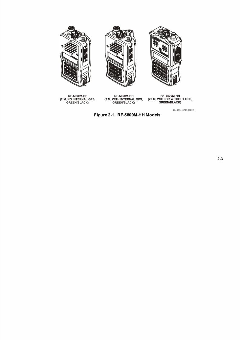
Figure 2-1. RF-5800M-HH Models
RF-5800M-HH(2 M, NO INTERNAL GPS,
GREEN/BLACK)
CL-0234-4200-0001B
RF-5800M-HH(2 M, WITH INTERNAL GPS,
GREEN/BLACK)
RF-5800M-HH(20 M, WITH OR WITHOUT GPS,
GREEN/BLACK)
7/21/2019 RF-5800M HH Ops Manual
http://slidepdf.com/reader/full/rf-5800m-hh-ops-manual 32/199
2-4
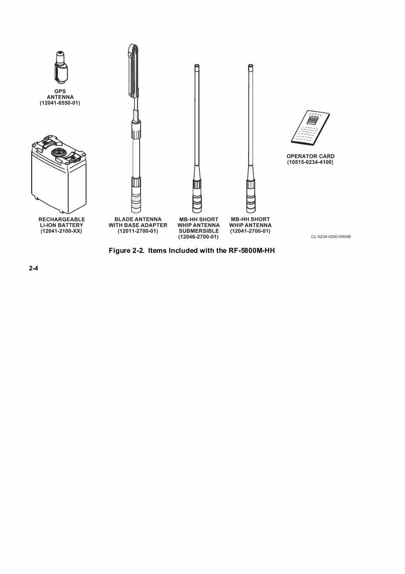
Figure 2-2. Items Included with the RF-5800M-HH
CL-0234-4200-0004B
RECHARGEABLELi-ION BATTERY(12041-2100-XX)
MB-HH SHORTWHIP ANTENNA(12041-2700-01)
OPERATOR CARD(10515-0234-4100)
MB-HH SHORTWHIP ANTENNASUBMERSIBLE(12046-2700-01)
GPS
ANTENNA(12041-6550-01)
BLADE ANTENNAWITH BASE ADAPTER
(12011-2700-01)

7/21/2019 RF-5800M HH Ops Manual
http://slidepdf.com/reader/full/rf-5800m-hh-ops-manual 33/199
2-5
2.1.1 Optional Items
Optional items available for the RF-5800M-HH include:
• RF-3161-AT001 Body worn dipole antenna (12006-2400-02)
• Modified H-250 Handset (10075-1399)
• Headset (12011-0400-xx)
• RF-5853-CH001 Single-bay charger (12011-2400-01)
• RF-5853-CH002 Two-bay charger (12011-3100-01)
• RF-5853-CH006 Six-bay charger (12011-2300-01)
• Black or Green Battery options for RF-5800M-HH radio models (12011-2100-01 and -02)
• Data Cable, Side Connector to DB25 Synchronous (12011-0210-A006)
• Config/Fill Cable, Side Connector to DB9 Remote (12011-0200-A006)
• Retransmit cable (12011-0230-A050)
• Tactical Internet, Point-to-Point Protocol (PPP) Cable (12011-0775-A003/A006/A007)
• RF-6550V-PK002 Radio Programming Kit
• Radio Holster (RF-5932-CA001 Camo) (RF-5932-CA002 Black)
• Flipdown Radio Holster (RF-5933-CA001 Camo) (RF-5933-CA002 Black)
• Handset Radio Accessory bag (12041-1595-01)
• GPS Antenna Assembly (12041-6550-01)

7/21/2019 RF-5800M HH Ops Manual
http://slidepdf.com/reader/full/rf-5800m-hh-ops-manual 34/199
2-6
• RF-5852-CH001 Vehicular Charger/Power Supply
• Broadband Antenna 30 - 512 MHz
The RF-5800M-HH can operate with the whip antenna over the entire 30 MHz to 512 MHz range of the radio. The
blade antenna is designed for use over the range of 30 MHz to 108 MHz. Other antennas may be used if they have
a 50-ohm input impedance and use a Threaded N-Connector (TNC). For the GPS antenna, other antennas may be
used if they have a 50-ohm input impedance and use a Sub-Miniature B (SMB) connector.
2.2 BATTERY INSTALLATION
The RF-5800M-HH includes a rechargeable Li-ION battery pack. The following paragraphs contain operating
warnings and cautions about the battery. Refer to Paragraph 5.3 for battery maintenance information.
2.2.1 Battery Safety
Observe the following warnings and cautions:
WARNING
Do not crush, disassemble, reverse polarity, incinerate, ormutilate the lithium-ion battery. Do not expose to fire or
temperatures above 160° F (71° C).
7/21/2019 RF-5800M HH Ops Manual
http://slidepdf.com/reader/full/rf-5800m-hh-ops-manual 35/199
2-7
WARNING
If the battery becomes hot, a hissing sound is heard, or an
irritating smell occurs, clear the area. Contact your local
authority for clean up instructions.
WARNING
Use only chargers approved by Harris, and never attempt to
modify the battery or charger, or attempt to charge a
disposable battery. Doing so may result in injury or death
and/or damage to the battery and the radio.
CAUTIONCAUTION
ACID CONTAMINATES LITHIUM-ION BATTERIES.
Every effort must be made to keep lithium-ion batteries
isolated from lead-acid batteries because lead-acid batteriescontain sulfuric acid. DO NOT use the same tools and
materials, such as screwdrivers, wrenches, syringes,
hydrometers, and gloves for both types of batteries. Any trace
of acid or acid fumes will permanently damage lithium-ion
(Li-ION) batteries on contact.
7/21/2019 RF-5800M HH Ops Manual
http://slidepdf.com/reader/full/rf-5800m-hh-ops-manual 36/199
2-8
2.2.2 Antenna Connections
Several types of antennas may be connected to the top of the RF-5800M-HH. The GPS antenna (12041-6550-01) is
only available for RF-5800M-HH models that support GPS capability. Likewise, the 20 m Short Whip Antenna
(12046-2700-01) is only available for RF-5800M-HH 20 m models. The Blade Antenna with Base Adapter (12011-
2700-01) and the MB-HH Short Whip Antenna (12041-2700-01) are available to all RF-5800M-HH models. Refer
to Table 2-1 for a list of items included with each RF-5800M-HH model type and see Figure 2-2.
2.2.3 Data Cable Connections
Several types of data cables may be connected for programming the RF-5800M-HH. There is a side connector on
the RF-5800M-HH for data cable connection. Refer to Table 2-1 for a list of items included with each RF-5800M-
HH model type.
2.2.4 Audio Connections
A six pin audio connector, located on the top of the RF-5800M-HH, is available for audio (microphone) connections.
Refer to Table 2-1 for a list of items included with each RF-5800M-HH model type.
2.2.5 GPS Connections
If equipped with internal GPS functionality, the GPS antenna (12041-6550-01) connects to the top of the RF-
5800M-HH. GPS is an optional configuration. Refer to Table 2-1 for a list of items included with each RF-5800M-
HH model type and see Figure 2-2.
7/21/2019 RF-5800M HH Ops Manual
http://slidepdf.com/reader/full/rf-5800m-hh-ops-manual 37/199
2-9
2.3 EQUIPMENT SETUP
See Figure 2-3. Perform the following procedure to set up the RF-5800M-HH:
a. The lithium-ion battery has a quick twist mount for easy connect and disconnect. Attach battery totransceiver by seating the battery on the base of the radio at an angle to the base, and then twist the battery into position in a clockwise direction as viewed from the bottom of the battery. The battery latchon the side of the radio snaps into the lock position when the battery is properly positioned on the radio.
Refer to Paragraph 5.3 for information on batteries and recharging batteries.
b. Connect the optional handset, if used, to the audio connector on top of the transceiver.
c. Screw either the blade antenna or short whip antenna to the antenna connector on top of the transceiver
• If using the blade antenna, connect antenna base to the transceiver by holding and turning the
adapter body. Connect antenna to base.
CAUTIONCAUTION
If a blade antenna is used, attach base to transceiver by
holding and turning the base adapter. Holding and turning the
blade antenna can damage the RF antenna connector on the
transceiver.
• The short whip antenna does not require an antenna base adapter and can be connected directly to
the antenna connector on the transceiver.
d. If the radio is equipped with internal GPS, screw the GPS antenna into the GPS connector on top of thetransceiver.

7/21/2019 RF-5800M HH Ops Manual
http://slidepdf.com/reader/full/rf-5800m-hh-ops-manual 38/199
2-10
2.4 EQUIPMENT TEARDOWN
See Figure 2-3. Perform the following procedure to tear down the RF-5800M-HH:
a. Zeroize the radio to erase communications plan, Transmission Security (TRANSEC) information, andCommunication Security (COMSEC) information. Refer to Paragraph 3.12.
b. Turn the radio function switch to the OFF position.
c. Disconnect the antenna from the antenna base (if used). If no antenna base is used, disconnect theantenna from the antenna connector on the radio.
CAUTIONCAUTION
If a blade antenna is used, remove base from transceiver by
holding and turning the adapter. See Figure 2-2. Holding and
turning the blade antenna can damage the RF antenna
connector on the transceiver.
d. Disconnect the antenna base (if used) from the antenna connector.
e. Disconnect the handset (if used) from the audio connector.
f. If equipped with internal GPS, disconnect the GPS antenna from the GPS antenna connector.
g. Remove battery from the transceiver by sliding the battery latch up towards the data connector. Holdthe battery latch in this raised position while rotating the battery in the counterclockwise direction asviewed from the bottom of the battery. Refer to Paragraph 5.3 for information on battery life, recharging batteries, and proper handling and disposal of batteries.

7/21/2019 RF-5800M HH Ops Manual
http://slidepdf.com/reader/full/rf-5800m-hh-ops-manual 39/199
2-11
Figure 2-3. Typical Equipment Setup and Teardown
CL-0234-4200-0002
HANDHELDWHIP ANTENNA
GPS ANTENNA
RF-5800M-HHMULTIBAND
TRANSCEIVER
RECHARGEABLELi-ION BATTERY
BATTERYLATCH

7/21/2019 RF-5800M HH Ops Manual
http://slidepdf.com/reader/full/rf-5800m-hh-ops-manual 40/199
2-12
This page intentionally left blank.
7/21/2019 RF-5800M HH Ops Manual
http://slidepdf.com/reader/full/rf-5800m-hh-ops-manual 41/199
3-1
CHAPTER 3
RADIO OPERATION
3.1 INTRODUCTION
This chapter provides instructions on how to operate the RF-5800M-HH. The user should first review Paragraph 3.3
to become familiar with the radio controls, indicators and connectors.
3.2 OPERATION TASK SUMMARY
Radio operation tasks, in general, are performed in the following order:
• Power on radio - Paragraph 3.4
• Radio lock/unlock - Paragraph 3.5
• Keypad lock/unlock - Paragraph 3.6
• Test radio - Paragraph 3.7
• Select Plain Text (PT) or Cipher Text (CT) - Paragraph 3.10
• Perform basic operations using net presets - Paragraph 3.11
Some operations can be performed at any time during normal operations and consist of:
• Optional tests - Paragraph 3.7.2, Paragraph 3.7.3, Paragraph 3.7.4
• Display lamp operation - Paragraph 3.8
• Zeroize radio - Paragraph 3.12

7/21/2019 RF-5800M HH Ops Manual
http://slidepdf.com/reader/full/rf-5800m-hh-ops-manual 42/199
3-2
• Set radio options - Paragraph 3.13
• Net scanning - Paragraph 3.14
• Remote control mode - Paragraph 3.15.1
• Retransmit mode - Paragraph 3.15.3
• Clone mode - Paragraph 3.15.4
NOTE
Advanced features covered in Appendix B include Directed
Calling, RF-6010 Basestation support, Situational Awareness
(SA), Wireless IP Network, Short Messaging Service (SMS),
and Falcon Watch™ Sensor Alerts.
3.3 CONTROLS, INDICATORS, AND CONNECTORS
Figure 3-1 show the controls, indicators, and connectors for the 2 m models of the RF-5800M-HH. Figure 3-2 shows
the controls, indicators, and connectors for the 20 m models of the RF-5800M-HH. Table 3-1 describes the controls,
indicators, and connectors for all models.
NOTE
Whenever 2 m or 20 m is discussed in this manual, it is
referring to the salt water submersion rating in meters (not
wavelength).

7/21/2019 RF-5800M HH Ops Manual
http://slidepdf.com/reader/full/rf-5800m-hh-ops-manual 43/199
3-3
Figure 3-1. Controls, Indicators, and Connectors for RF-5800M-HH (2 m Models)
CL-0234-4200-0003
12
11
9
10
3
1
2
4 75 6
8
13
7/21/2019 RF-5800M HH Ops Manual
http://slidepdf.com/reader/full/rf-5800m-hh-ops-manual 44/199
3-4
Figure 3-2. Controls, Indicators, and Connectors for RF-5800M-HH (20 m Model)
CL-0234-4200-0005A
12
11
3
1
2
4
75 6
9
10
13

7/21/2019 RF-5800M HH Ops Manual
http://slidepdf.com/reader/full/rf-5800m-hh-ops-manual 45/199
3-5
Table 3-1. RF-5800M-HH Controls, Indicators, and Connectors
Key(Figure 3-1,Figure 3-2)
Control/Indicator Function
1 Monitor Toggles squelch on and off.
2 PTT Push-To-Talk switch.
3 Volume Control UP arrow increases volume.DOWN arrow decreases volume.
4 Microphone Built-in microphone.
5 Audio Connector Provides a connection for an optional handset or headset.
6 Antenna Connector Provides a 50-ohm antenna port for a Threaded N-Connector(TNC).
7 Function Switch
OFF Turns RF-5800M-HH off.
1 through 5 Selects radio presets 1 through 5.
SCAN Places the radio in Scan mode, if scan is enabled.
FP Places the radio in Front Panel (FP), permitting access to all netsand keypad functions.
Z-ALL Zeroizes all programmed variables, including encryptionvariables; requires momentarily moving toggle switch to the “Z” position. (2 m models only) (Z-ALL brings up the ZERO ALLMENU on 20 m models only.)

7/21/2019 RF-5800M HH Ops Manual
http://slidepdf.com/reader/full/rf-5800m-hh-ops-manual 46/199
3-6
8 Toggle Switch (2 m models only)
PT Places the radio in Plain Text (PT) mode.
CT Places the radio in the Cipher Text (CT) encryption mode.Z Zeroizes all programmed values, including COMSEC and
TRANSEC variables. Also requires function switch in Z-ALL position to zeroize (Momentary).
9 Side Connector Provides connection for remote control operations, external GPS,or data device.
10 Battery Latch Releases battery for removal.
11 Keypad Buttons
0 (zero) The Circular Arrow button shows alternate displays. Refer toParagraph 3.11.
[CALL] (1 ABC) Used for Wireless IP, Directed Calling. Refer to Paragraph B.3.[LT] (2 DEF) Provides access to the Keypad/Display backlight control menu.
Refer to Paragraph 3.8 and see Figure 3-5.
[MODE] (3 GHI) Allows the operator to change the radio's operating mode. SeeFigure 3-3.
[ZERO] (5 MNO) Provides access to the radio's zeroize menus. See Figure 3-8.
[OPT] (7 STU) Provides access to the radio's options menus. See Figure 3-9.
Table 3-1. RF-5800M-HH Controls, Indicators, and Connectors (Continued)
Key(Figure 3-1,Figure 3-2)
Control/Indicator Function

7/21/2019 RF-5800M HH Ops Manual
http://slidepdf.com/reader/full/rf-5800m-hh-ops-manual 47/199
3-7
[PGM] (8 VWX) Provides access to the radio's programming menus. SeeFigure 4-1.
[CLR] Returns a field to its previous value, and activates the previousmenu. Also will terminate a call while in a Directed Call.
[ENT] Enter. Selects scroll field choices or locks in entry field data.
[PRE +/-] Scrolls the operator through the programmed nets when the modeswitch is in the FP position.
and buttons Allows the operator to move the cursor to the left or right, or toselect a new menu field.
and buttons Allows the operator to step through a scroll field list.
12 Display Displays operational and programming screens.
13 GPS Antenna Connector Antenna connector for internal GPS.
Table 3-1. RF-5800M-HH Controls, Indicators, and Connectors (Continued)
Key(Figure 3-1,Figure 3-2)
Control/Indicator Function
7/21/2019 RF-5800M HH Ops Manual
http://slidepdf.com/reader/full/rf-5800m-hh-ops-manual 48/199
3-8
3.3.1 Number Entry
Alphanumeric fields are used to enter alphanumeric strings such as net names, security, and passwords. When
selecting an alphanumeric field, the entire field flashes. Once a character is entered, only the next character to be
updated flashes. This flashing character is the cursor.
• Each numeric button on the keypad (except 0) is assigned up to three letters of the alphabet. For example,
the 1 button is also assigned the letters A, B, and C. To enter a 1 in a field, press the 1 button once, to enter
an A, press the 1 button twice, etc.
NOTE
When using SMS, the button sequence is slightly different.
Press the 1 button once to enter an A, press the 1 button twice
to enter B, press the 1 button three times to enter a C, and press
the 1 button four times to enter a 1.
• To advance the cursor to the next position, another button must be pressed. This automatically advances the
cursor to the next position.
• If two consecutive letters need to be entered from the same button, the right arrow button must be pressed
to advance the cursor.
• Blank spaces in a text string are entered by pressing the 0 button twice.
• The CLR button backspaces one digit and then clears all digits to the right of the cursor.
NOTE
When using SMS, the CLR button deletes all digits.

7/21/2019 RF-5800M HH Ops Manual
http://slidepdf.com/reader/full/rf-5800m-hh-ops-manual 49/199
3-9
3.4 RADIO POWER-ON
To power on the RF-5800M-HH, rotate the function switch from OFF to either the 1 - 5, SCAN, or FP position.
This initializes the radio and performs a self-test. When the test is complete, the net preset screen is displayed.
NOTE
The keypad may be locked to prevent accidental button
operation. Before proceeding with keypad functions, unlock
the keypad as described in Paragraph 3.6.2.
When using the RF-5800M-HH with the optional RF-5800M-V520 Vehicular Adapter Amplifier (VAA), set the
operating mode to VAA (refer to Paragraph 3.15.8). This allows the radio to be used with simple “Jerk and Run”
operation.
3.5 RADIO LOCK
The Radio Lock function provides the capability to completely disable all keypad and all push-button functions of
the radio. This eliminates the potential for any inadvertent key presses while the radio is turned on. The top function
switch will remain operable even with the radio locked, allowing for CT and PT audio connections. See Figure 3-11
3.5.1 Locking the Radio
Perform the following procedure to lock the radio:
a. Press the [MODE] button.
b. Use the up/down arrow buttons to select RADIO LOCK, and press [ENT].
c. RADIO LOCKED will be seen on the display.

7/21/2019 RF-5800M HH Ops Manual
http://slidepdf.com/reader/full/rf-5800m-hh-ops-manual 50/199
3-10
3.5.2 Unlocking the Radio
Perform the following procedure to unlock the radio:
a. Press the [CLR] button five times.
b. The radio controls will be unlocked.
3.6 KEYPAD LOCK
The Keypad Lock function provides the capability to lock the radio keypad, while still allowing the PTT, squelch
and volume controls to operate. The Keypad Lock security function reduces the potential for inadvertent key presses
that may adversely affect radio operation or programming. See Figure 3-11.
3.6.1 Locking the Keypad
Perform the following procedure to lock the keypad:
a. Press the [MODE] button.
b. Use the up/down arrow buttons to select KEYPAD LOCK, and press [ENT].
NOTE
Locking the keypad does not disable the Monitor (squelch
button), MIC Push-to-Talk (PTT), Volume controls, or Zero
(0) button.
7/21/2019 RF-5800M HH Ops Manual
http://slidepdf.com/reader/full/rf-5800m-hh-ops-manual 51/199
3-11
3.6.2 Unlocking the Keypad
Perform the following procedure to unlock the keypad:
a. Press the [MODE] button.
b. Enter the programmed operator security level 0 password and press [ENT] to unlock the keypad. Ifthere is no password, simply press [ENT] to unlock.
NOTE
If remote control and keypad lock are both enabled, remote
control should be turned off prior to turning off keypad lock.
Refer to Paragraph 3.15.1 for information on remote control.
3.7 INITIAL TESTS
The following paragraphs provide tests that should be performed to ensure operational readiness of the
RF-5800M-HH.
WARNING
To avoid damage to hearing, check the volume level before
using the radio.

7/21/2019 RF-5800M HH Ops Manual
http://slidepdf.com/reader/full/rf-5800m-hh-ops-manual 52/199
3-12
WARNING
To prevent electrical shock and Radio Frequency (RF) burns
avoid making RF power output connections or touching the
antenna while in transmit mode.
3.7.1 Automatic Test
See Figure 3-3 for the Mode>Test menu tree. Use the following procedure to perform an automatic test:
a. Press the [MODE] button.
b. Use the up/down arrow buttons to select TEST and press [ENT].
c. Select AUTO and press [ENT].
d. If the radio displays a fault code, refer to Chapter 5 for troubleshooting. If no fault codes are displayed,the radio is ready for operation.
3.7.2 Optional Manual Tests
See Figure 3-3 for the Mode>Test menu tree. Use the following procedure to perform manual tests:
a. Press the [MODE] button.
b. Use the up/down arrow buttons to select TEST and press [ENT].
c. Select MANUAL and press [ENT].
7/21/2019 RF-5800M HH Ops Manual
http://slidepdf.com/reader/full/rf-5800m-hh-ops-manual 53/199
3-13
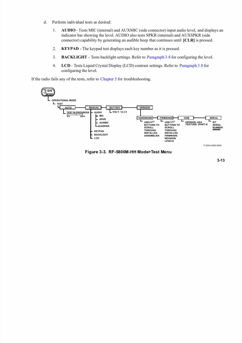
d. Perform individual tests as desired:
1. AUDIO - Tests MIC (internal) and AUXMIC (side connector) input audio level, and displays an
indicator bar showing the level. AUDIO also tests SPKR (internal) and AUXSPKR (side
connector) capability by generating an audible beep that continues until [CLR] is pressed.
2. KEYPAD - The keypad test displays each key number as it is pressed.
3. BACKLIGHT - Tests backlight settings. Refer to Paragraph 3.8 for configuring the level.
4. LCD - Tests Liquid Crystal Display (LCD) contrast settings. Refer to Paragraph 3.8 for
configuring the level.
If the radio fails any of the tests, refer to Chapter 5 for troubleshooting.
Figure 3-3. RF-5800M-HH Mode>Test Menu
F-0234-4200-0004
OPERATIONAL MODE
TEST
TEST IN PROGRESS
0% 100%
USEBUTTONS TOSCROLL
THROUGHINSTALLED
ASSEMBLIES
USEBUTTONS TOSCROLL
THROUGHINSTALLED
FIRMWAREREVISIONLEVELS
VERSION: V#.#FEATURE: (PART #)
R/TSERIALNUMBER######
KEYPAD
BACKLIGHT
LCD
AUDIO
MIC
SPKR
AUXMIC
AUXSPKR
VOLT: 12.3 V
HARDWARE FIRMWARE OVM SERIAL
AUTO MANUAL BATTERY VERSION
3 GHI
MODE

7/21/2019 RF-5800M HH Ops Manual
http://slidepdf.com/reader/full/rf-5800m-hh-ops-manual 54/199
3-14
3.7.3 Battery Test
See Figure 3-3 for the Mode>Test menu tree.
The RF-5800M-HH uses the smart features of the Li-ION battery to indicate the absolute (or true) state of charge.
The true capacity of a battery will lessen with age. This means that while a charger may indicate a full charge, an
old battery may not have the same capacity (or operating time) as a new battery. The battery display shown in
Figure 3-4 bases the 100% level on a new, fully charged battery. An older battery may not indicate 100% even if
fully charged. The battery may still be used, but operating time may be less than expected.
For more information on using the battery, refer to Paragraph 5.3. Do the following to perform a battery test:
a. Press the [MODE] button.
b. Use the up/down arrow buttons to select TEST and press [ENT].
c. Use the left/right arrow buttons to select BATTERY and press [ENT]. The radio displays actual chargecapacity in percentage form with a graphical intensity meter display. Battery voltage level is alsodisplayed numerically. See Figure 3-4.
Figure 3-4. Battery Display
F-0234-4200-0005
0%
BATTERY
73%12.3 V
100%

7/21/2019 RF-5800M HH Ops Manual
http://slidepdf.com/reader/full/rf-5800m-hh-ops-manual 55/199
3-15
3.7.4 Optional Version Tests
See Figure 3-3 for the Mode>Test menu tree. Use the following procedure to perform version tests:
a. Press the [MODE] button.
b. Use the up/down arrow buttons to select TEST and press [ENT].
c. Use the left/right arrow buttons to select VERSION and press [ENT].
d. Select and check individual versions as desired:
1. HARDWARE
2. FIRMWARE
3. OVM (Option Validation Matrix)
4. SERIAL (serial number of radio)
3.8 LT BUTTON OPERATION
See Figure 3-5. To configure the Keypad/Display backlight operation, intensity and contrast, press the LT button.
a. To have the backlight remain on for a short time after any button is pressed, use the up/down arrow buttons to select MOMENTARY, then press [ENT]. To have the backlight remain continuously on,select ON, then press [ENT]. To disable the backlight, select OFF, then press [ENT].
b. Use the left/right arrow buttons to adjust the backlight intensity, then press [ENT].
c. Use the left/right arrow buttons to adjust the display contrast, then press [ENT] to exit.

7/21/2019 RF-5800M HH Ops Manual
http://slidepdf.com/reader/full/rf-5800m-hh-ops-manual 56/199
3-16
3.9 BEFORE OPERATING THE RF-5800M-HH
Before operating the RF-5800M-HH, the net presets, traffic encryption keys, addresses, etc. must be established.
Parameters can be programmed through the radio front panel per Chapter 4, or by using RF-6550V VHF-UHF Radio
Programming Application software (supplied separately).
Figure 3-5. Other RF-5800M-HH Keypad/Display Button Menu Trees
LIGHT OPERATION
OFF
MOMENTARY
ON
LIGHT INTENSITY
CONTRAST
2DEF
LT
F-0234-4200-0006

7/21/2019 RF-5800M HH Ops Manual
http://slidepdf.com/reader/full/rf-5800m-hh-ops-manual 57/199
3-17
3.9.1 Voice/Data and Cipher Text Compatibility
Table 3-2 shows the operational mode capabilities of the RF-5800M-HH.
Table 3-2. Voice/Data Compatibility
Operating
Mode
Intended
Operation
Data/Voice
(D/V)Voice
Fixed
Frequency
Modulation
PT
SimpleVOC CLEAR FM
D/V CLEAR WBFSK
DATA NONE WBFSK
Wireless IP/Directed
VOC CVSD WBFSK
D/V CVSD WBFSK
DATA NONE WBFSK
CT Simple, Directed,Wireless IP
VOC CVSD WBFSK
D/V CVSD WBFSK
DATA NONE WBFSK

7/21/2019 RF-5800M HH Ops Manual
http://slidepdf.com/reader/full/rf-5800m-hh-ops-manual 58/199
3-18
3.9.2 Cipher Text Compatibility
Radios can communicate using Cipher Text (CT) only if they have exactly the same version of CITADEL
encryption. Perform the following procedure to determine CITADEL version number:
a. Press the [MODE] button. Select TEST and press [ENT].
b. Select VERSION and press [ENT].
c. Select HARDWARE and press [ENT].
d. Use the up/down arrow buttons to scroll to the CITADEL version menu.
e. Verify that the Harris part numbers match exactly. (e.g.: 10561-8010-XXXX; where the XXXX fieldcorresponds with the CITADEL encryption version in the radio.)
3.10 SELECTING PT OR CT
On 2 m models, place the toggle switch in the PT (plain text) or CT (encrypted) position; the selection can be viewed
on the LCD display. On 20 m submersible models, use the left/right arrow keys to scroll to the PT/CT field and then
select CT or PT using the up/down arrow keys. Refer to Paragraph 3.9.2 for the procedure to verify CT
compatibility.
3.11 BASIC OPERATION FROM NET PRESET
The RF-5800M-HH uses net presets to simplify radio operation. The following paragraphs explain how to set up
and use net presets.
7/21/2019 RF-5800M HH Ops Manual
http://slidepdf.com/reader/full/rf-5800m-hh-ops-manual 59/199
3-19
3.11.1 Overview - Contents of a Net Preset
A net preset associates an encryption key, voice/data setting, squelch setting, and power level to a fixed frequency
or a hopnet. This hierarchy lessens the amount of manually programmed parameters in the radio. For instance, a user
may use several encryption keys or data rates for a particular frequency or hopnet. All this information can be pre-
programmed into the radio and stored as a net preset for simple access.
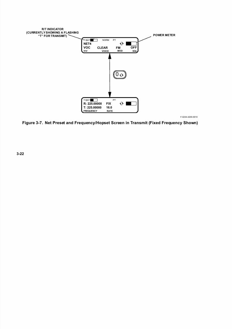
3.11.2 LCD Display - Preset Screens
The system preset screen, shown on the top of Figure 3-6 and Figure 3-7, is used to view and change net presets.
The channel preset screen, shown on the bottom of Figure 3-6 and Figure 3-7, is used to view and change frequency
or hopset settings. Some points to remember with these screens are:
• To change settings, use the and keys to scroll to the setting, use to scroll choices, and press [ENT]
to accept changes. When in FP, can only override settings when not transmitting.
• To toggle between the system preset and channel preset screen, use the key.
• The battery meter is temporarily replaced with the volume level indicator when the volume button is
pressed.
• The receive signal strength meter (S-Meter) changes to display a power level meter when the
RF-5800M-HH is transmitting.
• NORM is displayed for simple net presets.
• Only the net presets that are configured and enabled (activated in list) will be selectable. With the function
switch in FP position, use the [+PRE-] buttons to scroll through the available net presets. Net presets 1
through 5 can always be selected directly from the function switch.
0

7/21/2019 RF-5800M HH Ops Manual
http://slidepdf.com/reader/full/rf-5800m-hh-ops-manual 60/199
3-20
NOTE
Whenever the operator manually changes a preprogrammed
net parameter, the radio places an asterisk (*) to the right of the
net name on the LCD to indicate that changes have been made.
In addition to receive and transmit frequencies, the operator
can also change Data/Voice setting and squelch type.
Changing parameters in this way is called a temporary
override. For more information on temporary overrides, referto Paragraph 3.11.6.
NOTE
The radio function switch must be in the FP position to use the
[+PRE-] buttons.

7/21/2019 RF-5800M HH Ops Manual
http://slidepdf.com/reader/full/rf-5800m-hh-ops-manual 61/199
3-21
Figure 3-6. Net Preset and Frequency/Hopset Screen in Receive (Fixed Frequency Shown)
SIGNAL STRENGTH
METER
F-0234-4200-0009
VOICE MODE
DATA/VOICE
MODE
NET NAME
R/T INDICATOR
(CURRENTLY SHOWING ASTATIC“R” FOR RECEIVE)
BATTERY
METER S-METER LABEL
SQUELCH TYPE
MODULATION MODE
RECEIVE FREQUENCY
TRANSMIT FREQUENCY
NET TYPE
DATARATENOTES:1. PRESSING VOLUME BUTTONS CAUSES THE
VOLUME METER TO REPLACE THE
BATTERY METER FOR A SHORT TIME.2. THE BATTERY METER GIVES AN
INDICATION OF THE CHARGE CAPACITY OFTHE BATTERY.
VOC
NET4
D/V
PTR BAT NORM
OFFSQL
0
CLEAR FMVOICE MOD
S3 6 9+
T: 225.00000
R: 225.00000
FREQUENCY
PTR BAT
RATE
S3 6 9+
16.0
FIX
*
TEMPORARY OVERRIDE INDICATOR
CT/PT
SWITCH SETTING
MODENORM/HOP
7/21/2019 RF-5800M HH Ops Manual
http://slidepdf.com/reader/full/rf-5800m-hh-ops-manual 62/199
3-22
Figure 3-7. Net Preset and Frequency/Hopset Screen in Transmit (Fixed Frequency Shown)
F-0234-4200-0010
POWER METER
R/T INDICATOR
(CURRENTLYSHOWING A FLASHING“T” FOR TRANSMIT)
VOC
NET4
D/V
PTT BAT NORM
OFFSQL
CLEAR FMVOICE MOD
0
T: 225.00000
R: 225.00000
FREQUENCY
PTT BAT
RATE
16.0
FIX

7/21/2019 RF-5800M HH Ops Manual
http://slidepdf.com/reader/full/rf-5800m-hh-ops-manual 63/199
3-23
3.11.3 Select a Net Preset
Net presets are selected by using the [+PRE-] buttons to scroll the choices.
NOTE
Function switch must be in the FP position to use the
[+PRE-] buttons. The [+PRE-] buttons are disabled when the
function switch is placed in 1 - 5.
3.11.4 Data/Voice (D/V) Settings
The Data/Voice (D/V) field can be changed to Voice (VOC), Data/Voice (D/V), or DATA. The choices correspond
to the types of information that can be transmitted and received. Refer to Paragraph 3.9.1 for compatibility. The PTT
will be ignored if DATA is selected.
3.11.5 Squelch (SQL) Settings
The RF-5800M-HH supports digital squelch, analog tone squelch, and analog noise squelch. Noise and Tone
Squelch can be modified from the SQL field. Digital squelch requires that the radio receive a specific digital
waveform in order to break the radio's squelch. Analog tone squelch requires that a 150 Hz tone be transmitted along
with the normal radio traffic in order to break the receive radio's squelch. Analog noise squelch requires a signal thatis strong enough to break the radio's squelch be received on the radio's receive frequency.
Digital squelch is only available if the radio is in the CT position. If the radio is changed to PT from CT when VOC
or D/V is selected, the squelch type returns to the programmed analog squelch type.
The RF-5800M-HH can transmit EIA-standard Continuous Tone Coded Squelch System (CTCSS) tones in
Frequency Modulation (FM) mode, for use with repeater systems that utilize CTCSS. Refer to Paragraph 4.5.2.2 for
details on configuring the radio for CTCSS.

7/21/2019 RF-5800M HH Ops Manual
http://slidepdf.com/reader/full/rf-5800m-hh-ops-manual 64/199
3-24
3.11.6 Radio Programming Versus Temporary Overrides
It is important to understand the differences between programming and temporary overrides. The radio is
programmed either from the keypad or by loading a programming plan from VHF-UHF Radio Programming
Application (RPA) software. Programmed parameters are stored in non-volatile Random Access Memory (RAM)
until they are zeroized via user command. RAM is capacitor-backed for a short period after the main battery is
removed. A charged battery must be reinstalled within a short period to avoid losing programming data.
The operator can temporarily override some parameters from their programmed value. These changes are only validuntil the operator selects another net. Once this occurs, the temporary changes are lost. The operator must select the
SAVE command from the OPT menu in order to save the temporary overrides as programmed values. See
Figure 3-9.
NOTE
Saving temporarily overridden net parameters without
coordinating those net changes with the other net members
can compromise net and radio performance.
NOTE
Performing a temporary override may cause parameters of
lower precedence to be overridden. This is to ensure that all
radio parameters are consistent and work with one another.
The operator is not notified of these additional overrides.
7/21/2019 RF-5800M HH Ops Manual
http://slidepdf.com/reader/full/rf-5800m-hh-ops-manual 65/199
3-25
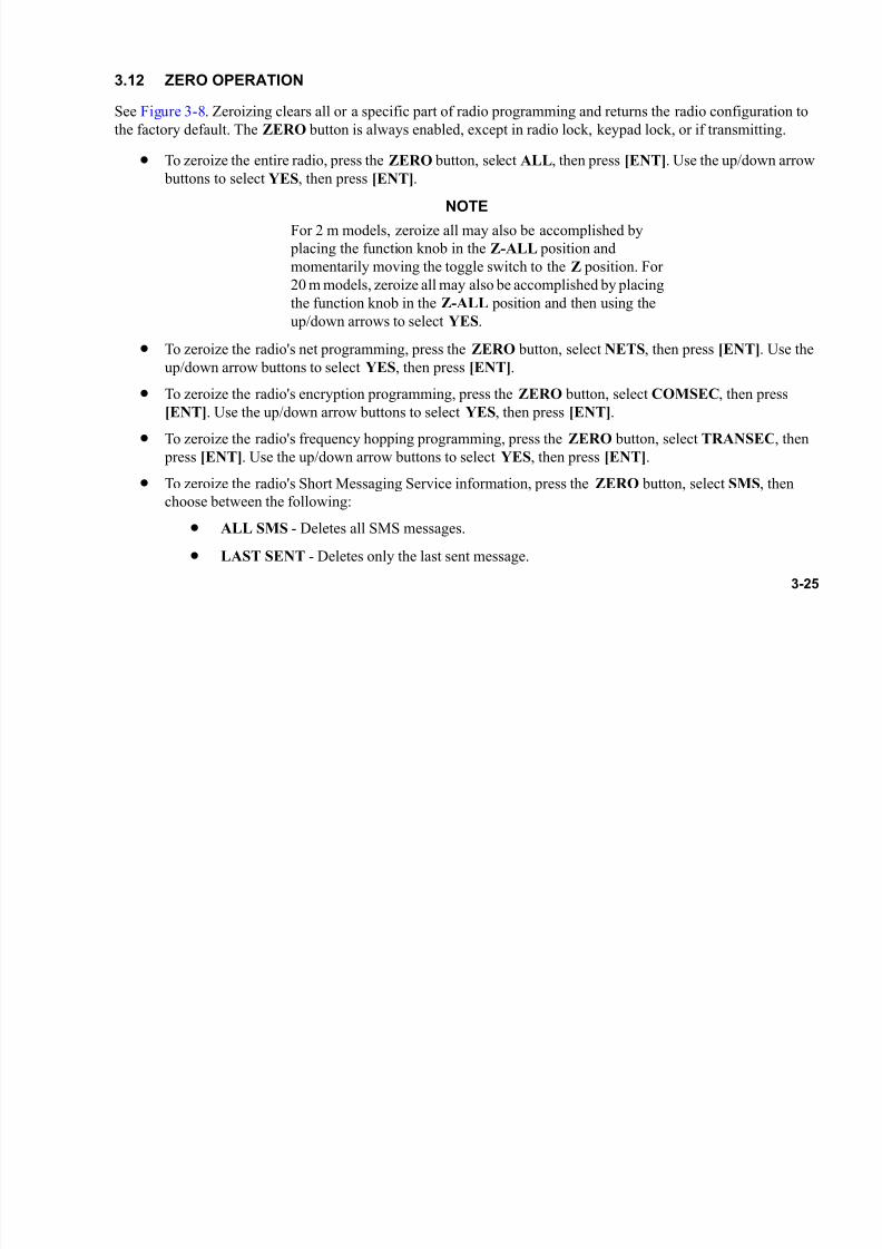
3.12 ZERO OPERATION
See Figure 3-8. Zeroizing clears all or a specific part of radio programming and returns the radio configuration to
the factory default. The ZERO button is always enabled, except in radio lock, keypad lock, or if transmitting.
• To zeroize the entire radio, press the ZERO button, select ALL, then press [ENT]. Use the up/down arrow
buttons to select YES, then press [ENT].
NOTEFor 2 m models, zeroize all may also be accomplished by
placing the function knob in the Z-ALL position and
momentarily moving the toggle switch to the Z position. For
20 m models, zeroize all may also be accomplished by placing
the function knob in the Z-ALL position and then using the
up/down arrows to select YES.
• To zeroize the radio's net programming, press the ZERO button, select NETS, then press [ENT]. Use the
up/down arrow buttons to select YES, then press [ENT].
• To zeroize the radio's encryption programming, press the ZERO button, select COMSEC, then press
[ENT]. Use the up/down arrow buttons to select YES, then press [ENT].
• To zeroize the radio's frequency hopping programming, press the ZERO button, select TRANSEC, then
press [ENT]. Use the up/down arrow buttons to select YES, then press [ENT].
• To zeroize the radio's Short Messaging Service information, press the ZERO button, select SMS, then
choose between the following:
• ALL SMS - Deletes all SMS messages.
• LAST SENT - Deletes only the last sent message.
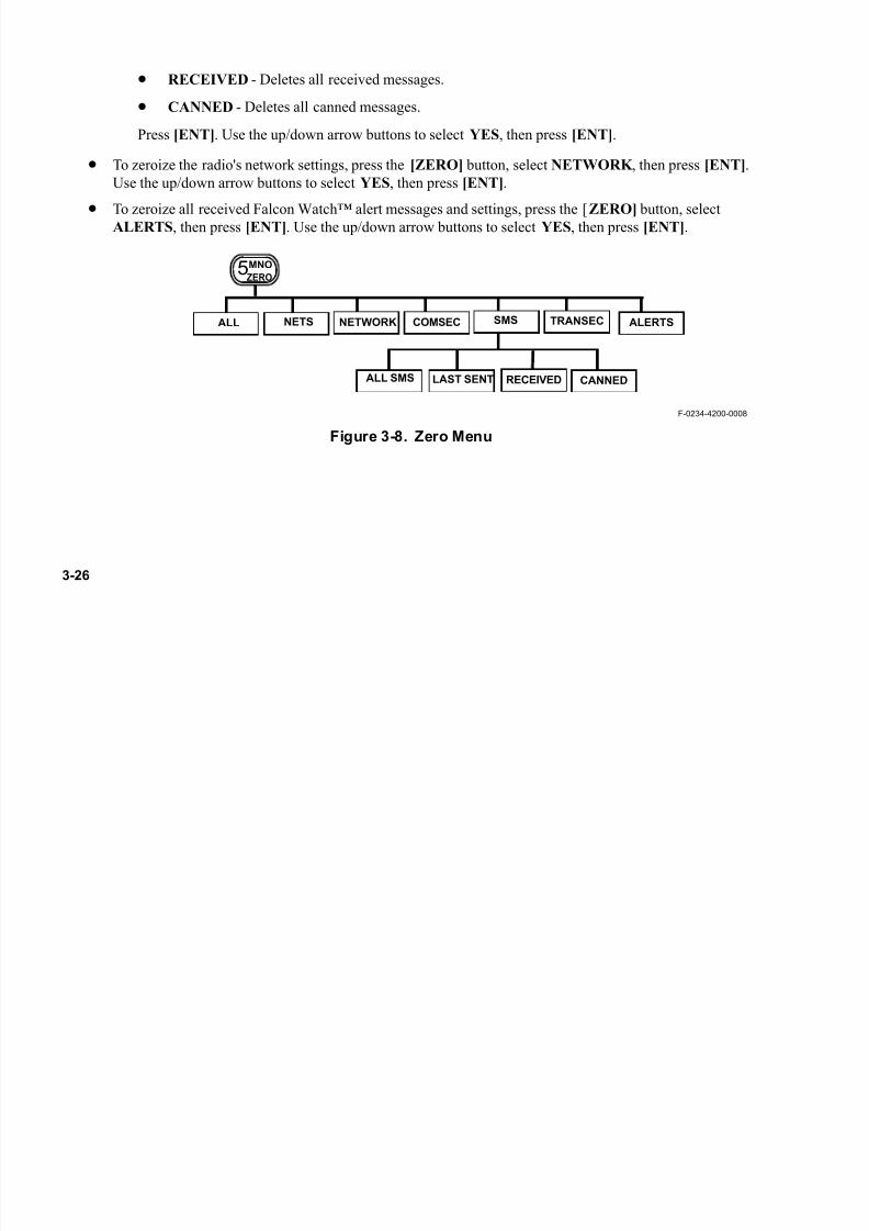
7/21/2019 RF-5800M HH Ops Manual
http://slidepdf.com/reader/full/rf-5800m-hh-ops-manual 66/199
3-26
• RECEIVED - Deletes all received messages.
• CANNED - Deletes all canned messages.
Press [ENT]. Use the up/down arrow buttons to select YES, then press [ENT].
• To zeroize the radio's network settings, press the [ZERO] button, select NETWORK , then press [ENT].
Use the up/down arrow buttons to select YES, then press [ENT].
• To zeroize all received Falcon Watch™ alert messages and settings, press the [ZERO] button, selectALERTS, then press [ENT]. Use the up/down arrow buttons to select YES, then press [ENT].
Figure 3-8. Zero Menu
5MNO
ZERO
F-0234-4200-0008
COMSECALL NETS NETWORK TRANSECSMS
ALL SMS LAST SENT RECEIVED CANNED
ALERTS

7/21/2019 RF-5800M HH Ops Manual
http://slidepdf.com/reader/full/rf-5800m-hh-ops-manual 67/199
3-27
3.13 RADIO OPTIONS
Figure 3-9 shows the RF-5800M-HH options menu tree. The following paragraphs describe the radio options
menus. Refer to Paragraph 4.3 for the complete programming menu tree.
Figure 3-9. RF-5800M-HH Options Menu Tree
TO BROWSE
REC’D MSGS
NET ## SAVED
F-0234-4200-0011
NOTES:
1. ONLY VISIBLE WHEN USING A FREQUENCY HOPPING NET.
7STU
OPT
SAVE
CAM
COMSEC
SPEAKERENABLE
SPKR
ON
OFF
GPS
VIEW
REPORT
RADIOSELF ID
RADIO
TRANSMITPOWER
POWER
HIGH
MEDIUM
LOW
LOCKSET: ##/#####.####-###.#####
LOCKSETS
(NOTE 1)
(NOTE 2)
CRYPTO MODE
MINERR
RESYNC
SMS
2. ONLY VISIBLE WHEN GPS IS CONNECTED.
SELECT
NEW
DELETE_ALL
3. ONLY USED WITH DIRECTED CALLING AND WIRELESS IP NETS. REFER TO
(NOTE 3)
PARAGRAPH B.7.
TO BROWSE
REC’D MSGS
ALERTS
SELECT
DISPLAY ALL
DELETE_ALL
(NOTE 3)
HQTOD
GPS_SYNC
USER_ENTRY
TEK
ENCRYPTION KEY
CAM LABEL

7/21/2019 RF-5800M HH Ops Manual
http://slidepdf.com/reader/full/rf-5800m-hh-ops-manual 68/199
3-28
3.13.1 SAVE
To save changes made from net preset displays, press the [OPT] button, then select SAVE and press [ENT]. For
more information on net programming, refer to Paragraph 4.5.2.
3.13.2 COMSEC
To view the Communications Security (COMSEC) setting for the active net, press the [OPT] button, select
COMSEC, then press [ENT]. The user next enters the Traffic Encryption Key (TEK) and the Citadel AlgorithmModification (CAM). CAM allows the user to add an additional layer of COMSEC encryption and is not
programmable from the RF-5800M-HH radio. CAM encryption is part of the initial programming process and is
loaded at the same time the radio plan is loaded.
For TEK, enter the encryption key and then the Crypto Mode. Valid mode options are:
• MINERR - This is the default mode. When using MINERR, the start of the transmission must be heard to
receive an encrypted transmission. There is a crypto sync that precedes the waveform. This mode is
supported across all net types: Simple, Directed Calling, and Wireless IP.
• RESYNC - This mode allows a radio on simple voice/data nets (not directed calling or wireless IP nets) to
receive an encrypted transmission already in progress. The radio does not have to hear the start of the
waveform, but can power on and start receiving in mid-transmission. RESYNC is more susceptible to noisethan MINERR.
3.13.3 Speaker (SPKR)
To toggle the radio speaker on or off, press the [OPT] button, then select SPKR . Use the up/down arrows to select
ON or OFF.

7/21/2019 RF-5800M HH Ops Manual
http://slidepdf.com/reader/full/rf-5800m-hh-ops-manual 69/199
3-29
3.13.4 GPS
To view the status of an internal or externally-connected GPS, press the [OPT] button, select GPS, then select
VIEW. Press the circular arrow key to switch between the satellite status, heading and velocity, and altitude pages.
Press the up/down arrow on each page to select status of the current radio or any radio reporting its position (refer
to Paragraph B.4.4 for information on position reporting).
3.13.5 RADIO
To view the Radio SELF ID (used for Directed Calling), press the [OPT] button, then select RADIO. Refer to
Paragraph B.3 for information about Directed Calling.
3.13.6 SMS
This menu allows the user to create and send new text messages, and to view, reply, forward and delete received text
messages. For detailed information about Short Messaging Service, refer to Paragraph B.6.
3.13.7 POWER
The transmit power level can be programmed for each net preset, or it can be set manually. To manually select either
HIGH, MEDIUM, or LOW transmit power, press the [OPT] button, then select POWER . Select the desired power
level, then press [ENT].
For FM, HIGH power is 5 watts, MEDIUM power is 2 watts, and LOW power is 0.25 watt. For Amplitude
Modulation (AM), HIGH power is 5 watts, MEDIUM power is 2 watts, and LOW power is 1 watt. Refer to
Paragraph 4.5.2 for information on how to program the power level for a net preset.

7/21/2019 RF-5800M HH Ops Manual
http://slidepdf.com/reader/full/rf-5800m-hh-ops-manual 70/199
3-30
3.13.8 ALERTS
This menu allows the user to:
• View stored Alert messages from the optional Falcon Watch™ Sensor Alarm System.
• Reset the filtering (Display All) for any Sensor Nodes that were previously filtered (Ignored).
• Delete all stored Alert messages.
For detailed information about Falcon Watch™ Sensor Alerts, refer to Paragraph B.7.
3.13.9 HQTOD
This menu allows the user to:
• Set the Time-Of-Day (TOD) manually.
• Set the TOD using Global Positioning System (GPS) and perform a GPS sync.
3.13.10 LOCKSETS (Hopping Only)
A lockset specifies frequencies that cannot be used during list or wideband frequency hopping. For more information
about locksets, refer to Paragraph 4.5.1.4. To view the frequency hopping lockset information for the active net, press the [OPT] button, select LOCKSETS, then press [ENT].
NOTE
LOCKSETS data is only available when the active net is a
frequency hopping net. LOCKSETS will not display on a
fixed frequency net.

7/21/2019 RF-5800M HH Ops Manual
http://slidepdf.com/reader/full/rf-5800m-hh-ops-manual 71/199
3-31
NOTE
Locksets that have been programmed into the radio apply to
all frequency hopping nets.
3.14 NET SCANNING
The RF-5800M-HH can be set for scan operation by placing the function switch in SCAN position. The radio will
search fixed frequency net presets for the presence of a Radio Frequency (RF) signal. The user can program a list ofup to 25 net presets into the scan list. This list is separate from the list of net presets that are activated in the list (for
use with the +PRE- button).
NOTE
Net Scanning is not available in frequency hopping modes.
The maximum number of nets that can be reliably scanned depends upon whether the radio is in PT or CT. A full
25-net scan list can be used in PT. Reliable operation in CT requires two procedural modifications because of the
preamble synchronization required by encrypted transmissions. First, the calling radio should have Robust Preamble
turned on (refer to Paragraph 4.8.1). This extends the transmitters preamble to give the scanning radio enough time
to synchronize after it scans all other nets in the scan list. Second, the number of nets in a CT scan list should be no
more than five with a sixth Receive (RX) Priority Net. It is possible to scan more nets in CT, but some calls may bemissed.
There are two ways to scan: automatic and manual. Use the [CLR] button to toggle between the two.
In automatic scan, the radio scans each net in the list for the presence of an RF signal. If a signal is present on a net,
the radio stops scanning and holds on that net for the programmed hold time. If no hold time is specified, the radio
remains on that net until signal presence is lost or the user presses [CLR] to continue automatic scan. If signal

7/21/2019 RF-5800M HH Ops Manual
http://slidepdf.com/reader/full/rf-5800m-hh-ops-manual 72/199
3-32
presence is lost during the hold time, the radio waits the programmed hang time before continuing to automatically
scan. For more information on hang time and hold time, refer to Paragraph 4.6.2.1.
To enter automatic scan, perform the following procedure:
a. Turn the function switch to the SCAN position. If SCAN is enabled, SCAN will initiate automatically.
NOTE
Pressing the PTT button while the radio is scanning causes theradio to transmit using the transmit priority net. Pressing the
PTT button while the radio is stopped on a net will cause the
radio to transmit on that net. For more information on the
transmit priority net, refer to Paragraph 4.6.2.
NOTE
Beacon mode is disabled during Scan operation. Refer to
Paragraph 3.15.2 for more information.
b. To switch to manual scan, press the [CLR] button. When not automatically scanning (the radio hasstopped on a net that has an RF signal, or has stopped because the operator has pressed the [CLR]
button), the radio is in manual scan.c. During manual scan, use the [+PRE-] button to manually scroll through the scan list.
d. To return to automatic scan, press the [CLR] button.

7/21/2019 RF-5800M HH Ops Manual
http://slidepdf.com/reader/full/rf-5800m-hh-ops-manual 73/199
3-33
NOTE
When the radio is not scanning because the [CLR] button has
been pressed or signal presence is detected, pressing the
circular arrow button switches between the scan displays. See
Figure 3-10.
e. To exit scanning, turn the Mode Switch to a position other than SCAN.
The scan displays provide information similar to the normal net preset displays. See Figure 3-10.
7/21/2019 RF-5800M HH Ops Manual
http://slidepdf.com/reader/full/rf-5800m-hh-ops-manual 74/199
3-34
Figure 3-10. SCAN Displays
F-0234-4200-0012
CLR OR SIGNAL PRESENCE IS DETECTED OR RADIO IS KEYED
AUTOMATIC SCAN
DISPLAY
MANUAL SCAN
DISPLAY
SCANNING
PRESS
PTR BAT SCAN
SCANFOR MANUALCLR
MANUAL SCAN
DISPLAY
VOC
NET4
D/V
PTR BAT SCAN
TONESQL
0
CLEAR FMVOICE MOD
S3 6 9+
T: 225.00000
R: 225.00000
FREQUENCY
PTR BAT
RATE
S3 6 9+
NONE
FIX
SCAN

7/21/2019 RF-5800M HH Ops Manual
http://slidepdf.com/reader/full/rf-5800m-hh-ops-manual 75/199
3-35
3.15 OPERATIONAL MODE MENU
Figure 3-11 shows the RF-5800M-HH MODE menu tree. The following paragraphs describe the radio MODE
menus.
Figure 3-11. RF-5800M-HH Mode Menu
F-0234-4200-0007A
REMOTE CONTROL (NOTE 1)OFF
ON
OPERATIONAL MODE
3GHIMODE
KEYPAD LOCK
RECEIVE
TRANSMIT
CLONE TYPE
NOTES:
1. ONLY APPEARS IF REMOTE CONTROL IS ENABLED.
2. TEST MENU IS SHOWN SEPARATELY IN PARAGRAPH 3.7.
BEACON
OFF
ON
RETRANSMIT
CLONE
CLONING FREQUENCY (###.##### MHz)
ENCRYPTION KEY (#####)
RADIO LOCK
TEST (NOTE 2)
OFF
ON-SYNC
ON-ASYNC
VAA
OFF
ON
7/21/2019 RF-5800M HH Ops Manual
http://slidepdf.com/reader/full/rf-5800m-hh-ops-manual 76/199
3-36
3.15.1 Remote Control
Remote control is only available when using a remote terminal or PC. Remote control can only be enabled from the
remote terminal or PC, not from the [MODE] button. Once enabled, remote control can be disabled using the
[MODE] button. See Figure 3-11.
NOTE
If remote control and keypad lock are both enabled, remote
control should be turned off before turning off keypad lock.
3.15.2 Beacon Mode
Placing the RF-5800M-HH in Beacon mode makes the radio transmit on a selected frequency by sending either a
constant tone or a user-selectable swept tone audio. The beacon can transmit on any frequency in the full range of
the radio (30 MHz to 512 MHz). Beacon mode frequency, tone type, power level, and duty cycle can be adjusted
from the PGM>CFIG>BEACON menu. Refer to Paragraph 4.8.2 for beacon configuration information.
See Figure 3-11 and perform the following procedure to activate the beacon:
a. Press the [MODE] button.
b. At the OPERATIONAL MODE prompt, use the up/down arrow buttons to select BEACON, and press[ENT].
c. At the BEACON MODE prompt, select ON and press [ENT].
d. The radio will begin transmitting on the configured beacon frequency and duty cycle. The beacontransmission is a repetitive cycle for both swept tone and tone settings.

7/21/2019 RF-5800M HH Ops Manual
http://slidepdf.com/reader/full/rf-5800m-hh-ops-manual 77/199
3-37
NOTE
Normal radio net transmission will override the beacon
transmission. If the radio is keyed while in Beacon Mode, the
beacon transmission will be stopped until the radio is
unkeyed.
NOTE
Beacon mode is disabled during Scan operation.
To exit Beacon mode:
a. Press the [MODE] button.
b. At the OPERATIONAL MODE prompt, use the up/down arrow buttons to select BEACON, and press[ENT].
c. At the BEACON MODE prompt, use the up/down arrow buttons to select OFF, and press [ENT].
3.15.3 Retransmit Mode
A retransmission or repeater station receives a signal transmitted on one frequency and retransmits that signal on
another frequency (on another radio), enabling communication over a greater range than is possible using individualradios. A retransmission or repeater station for extending communication range can be set up using two radios.
Two types of operation are available using the retransmit setup:
• Black Digital Retransmit operation - Paragraph 3.15.3.1
• Red Analog Retransmit operation - Figure 3.15.3.2
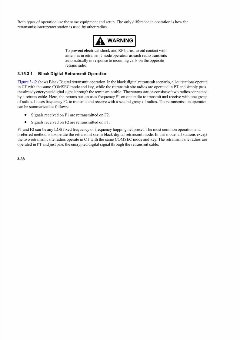
7/21/2019 RF-5800M HH Ops Manual
http://slidepdf.com/reader/full/rf-5800m-hh-ops-manual 78/199
3-38
Both types of operation use the same equipment and setup. The only difference in operation is how the
retransmission/repeater station is used by other radios.
WARNING
To prevent electrical shock and RF burns, avoid contact with
antennas in retransmit mode operation as each radio transmits
automatically in response to incoming calls on the opposite
retrans radio.
3.15.3.1 Black Digital Retransmit Operation
Figure 3-12 shows Black Digital retransmit operation. In the black digital retransmit scenario, all outstations operate
in CT with the same COMSEC mode and key, while the retransmit site radios are operated in PT and simply pass
the already encrypted digital signal through the retransmit cable. The retrans station consists of two radios connected
by a retrans cable. Here, the retrans station uses frequency F1 on one radio to transmit and receive with one group
of radios. It uses frequency F2 to transmit and receive with a second group of radios. The retransmission operation
can be summarized as follows:
• Signals received on F1 are retransmitted on F2.• Signals received on F2 are retransmitted on F1.
F1 and F2 can be any LOS fixed frequency or frequency hopping net preset. The most common operation and
preferred method is to operate the retransmit site in black digital retransmit mode. In this mode, all stations except
the two retransmit site radios operate in CT with the same COMSEC mode and key. The retransmit site radios are
operated in PT and just pass the encrypted digital signal through the retransmit cable.
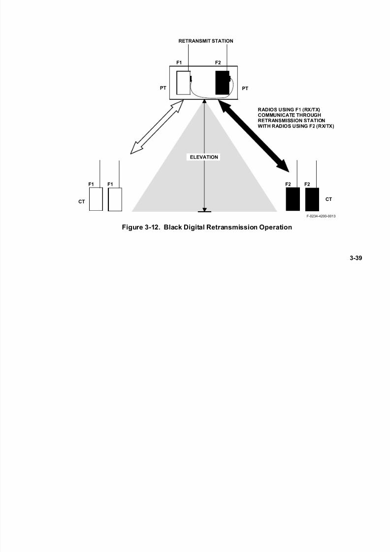
7/21/2019 RF-5800M HH Ops Manual
http://slidepdf.com/reader/full/rf-5800m-hh-ops-manual 79/199
3-39
Figure 3-12. Black Digital Retransmission Operation
F1 F1 F2 F2
F1 F2
RETRANSMIT STATION
RADIOS USING F1 (RX/TX)COMMUNICATE THROUGHRETRANSMISSION STATIONWITH RADIOS USING F2 (RX/TX)
ELEVATION
F-0234-4200-0013
PT PT
CTCT

7/21/2019 RF-5800M HH Ops Manual
http://slidepdf.com/reader/full/rf-5800m-hh-ops-manual 80/199
3-40
3.15.3.2 Red Analog Retransmit Operation
Figure 3-13 shows Red Analog retransmit operation. In Red Analog operation, all stations operate in CT mode, and
each net has its own COMSEC key and operating type. All radios are operated in CT and must be secured.
The retransmit station consists of two radios connected by a retransmit cable. The retransmit station uses frequency
F1 on one radio to transmit and receive with one group of radios. It uses frequency F2 to transmit and receive with
a second group of radios. The retransmission operation can be summarized as follows:
• Signals received on F1 are retransmitted on F2.
• Signals received on F2 are retransmitted on F1.
• Digital Squelch is used to disable PT override (if necessary).
F1 and F2 can be any LOS fixed frequency or frequency hopping net preset.

7/21/2019 RF-5800M HH Ops Manual
http://slidepdf.com/reader/full/rf-5800m-hh-ops-manual 81/199
3-41
Figure 3-13. Red Analog Retransmission Operation
F1 F1 F2 F2
F1 F2
RETRANS STATION
F-0234-4200-20
ELEVATION
CT CT
CTCT

7/21/2019 RF-5800M HH Ops Manual
http://slidepdf.com/reader/full/rf-5800m-hh-ops-manual 82/199
3-42
3.15.3.3 Repeater Retransmission Operation
Repeater operation is used when a net wants to gain extended range. All outstation radios that use the repeater station
for retransmission operate half-duplex nets, where the same frequency serves for both transmitting and receiving.
The repeater station uses simplex operation using separate transmit and receive frequencies.
Figure 3-14 shows repeater operation. The repeater receives on frequency F1 and transmits on frequency F2. With
this setup, all outstation radios transmit on F1 and receive on F2. Using this arrangement, all units must
communicate with each other through the repeater.

7/21/2019 RF-5800M HH Ops Manual
http://slidepdf.com/reader/full/rf-5800m-hh-ops-manual 83/199
3-43
Figure 3-14. Repeater Operation
F1
F2
F1RCV
F2TX
REPEATER STATION
ALL RADIOS COMMUNICATETHROUGH THE REPEATER
117F-011A
ELEVATION
ALL RADIOS:
TX-F1RCV-F2
7/21/2019 RF-5800M HH Ops Manual
http://slidepdf.com/reader/full/rf-5800m-hh-ops-manual 84/199
3-44
3.15.3.4 Hardware for Retransmission/Repeater Setup
The following equipment is used for retransmission/repeater operation:
• Two RF-5800M-HHs with antennas and battery packs
• Retransmit cable (12011-0230-A050)
NOTE
When using Retransmit mode, locking the keypad of the radio
will blank the radio’s display.
Figure 3-15 shows the retransmission/repeater hardware configuration. For optimum performance, the repeater site
should be elevated above the level of the outstations. Connect the retransmit cable to the side connector on each
radio. Separate the radio units by fully extending the retransmit cable to prevent receiver desensitization and RF
interference between units. For best retransmission performance, ensure the retransmit cable is in contact with the
ground along most of its length.
3.15.3.5 Frequency Separation
For simplex operation, F1 and F2 should not be within 20% of each other, and should not be harmonically related
(when one frequency is a whole number multiple of the second - for example: 60 MHz is the “first order” harmonic
of 30 MHz).
7/21/2019 RF-5800M HH Ops Manual
http://slidepdf.com/reader/full/rf-5800m-hh-ops-manual 85/199
3-45
Figure 3-15. Retransmission/Repeater Hardware Setup
SIDE CONNECTOR
F2
RECOMMENDED SEPARATION
DISTANCE:FULL CABLE LENGTH (50 FT.)
RETRANSMIT CABLE(12011-0230-A050)
RECOMMENDED FREQUENCY
SEPARATION: > 20%(NOT HARMONICALLY RELATED)
F1
SIDE CONNECTOR
F-0234-4200-0015
7/21/2019 RF-5800M HH Ops Manual
http://slidepdf.com/reader/full/rf-5800m-hh-ops-manual 86/199
3-46
3.15.3.6 Retransmit Settings
Determine whether Black Digital or Red Analog operation is required. Perform the following procedure to configure
the RF-5800M-HH:
a. Set the retransmit radios to the net preset that will be used for retransmission. The Robust Preamble setting (refer to Paragraph 4.8.1) should be set to ON when the RF-5800M-HH is being used inRetransmission/Repeater operation.
b. Turn radio switch to OFF.
c. Attach the retransmit cable to the side connector on both radios.
d. Turn on each RF-5800M-HH to PT position for black digital operation. Turn on each RF-5800M-HHto CT position for red analog operation.
e. Press the [MODE] button.
f. Use the up/down arrow keys to select RETRANSMIT and press [ENT].
g. Use the up/down arrow keys to select ON-SYNC or ON-ASYNC and press [ENT].
• ON-SYNC is used for backward compatibility with radio firmware prior to version 6.0.
• ON-ASYNC is used for radios with firmware version 6.0 or later.
NOTE
To determine the radio’s firmware version, press the [MODE] button then >TEST> VERSION>FIRMWARE.
7/21/2019 RF-5800M HH Ops Manual
http://slidepdf.com/reader/full/rf-5800m-hh-ops-manual 87/199
3-47
NOTE
Black frequency hopping is supported using
RETRANSMIT>ON-ASYNC mode only.
h. Begin retransmission operations. If one radio locks into continuous transmit, check for presence ofinterfering signals on the receiving radio and/or check squelch settings to determine if squelch falsingcondition exists. Digital squelch must be used in each of the retransmit radios to prevent falsingcondition where one radio is locked in transmit condition.
3.15.4 Clone Mode
The RF-5800M-HH is able to transfer most configuration parameters to identical handheld radios within a distance
of 20 feet (6 meters) using wireless cloning. The transferred data includes COMSEC keys, TRANSEC parameters,
NET PRESETS, and CONFIGURATION settings except for Wireless Internet (WIP) or Directed Call Nets. The
transferred data does not include backlight or volume settings. All clone data is transferred at LOW power in CT
mode (encrypted) regardless of the power setting and the PT/CT selection. The process requires one radio to be set
to transmit programming parameters, and the other radios set to receive them. See Figure 3-11.
3.15.4.1 Receiving Wireless Cloning Information
NOTEWhen performing the following procedure, ensure that the
radios are no more than 20 feet (6 meters) apart. This is the
maximum separation distance allowed.

7/21/2019 RF-5800M HH Ops Manual
http://slidepdf.com/reader/full/rf-5800m-hh-ops-manual 88/199
3-48
Any number of receive radios can be configured to accept cloning information. Perform the following procedure to
set up a radio for cloning receive operation:
a. Press the [MODE] button. Select CLONE and press [ENT].
b. Enter the desired frequency and press [ENT]. This defaults to the current radio frequency. This mustmatch the frequency used by the transmitting source radio.
c. Enter a six-digit numeric encryption key and press [ENT]. This key is used to encrypt the cloning data.The encryption key must match the key used by the transmitting source radio.
NOTE
This key is NOT the Traffic Encryption Key. This is only used
for the cloning process.
d. Select RECEIVE and press [ENT].
e. The radio displays AWAITING RECEIVE. A progress meter is shown on the next display line.
NOTE
Press [CLR] to abort setting up a radio for cloning receive
operation.
f. Display changes to RECEIVING as information is received. Progress meter increases to 100%.
g. On successful receipt of information, display changes to RECEIVE COMPLETE ANY KEY TOEXIT.

7/21/2019 RF-5800M HH Ops Manual
http://slidepdf.com/reader/full/rf-5800m-hh-ops-manual 89/199
3-49
h. If information is not successfully received, any of the following error messages may be seen:
1. Receive failure - data integrity failure, wrong encryption key: RECEIVE FAILURE ANY KEY
TO EXIT.
2. Software version failure - attempting to clone between dissimilar software versions: VERSION
MISMATCH ANY KEY TO EXIT.
3. Wrong radio type - attempting to clone between dissimilar radios.: INVALID RADIO TYPES
ANY KEY TO EXIT.
3.15.4.2 Transmitting Wireless Cloning Information
Verify that all target radios have been prepared to receive the cloning information. All target radios must display
AWAITING RECEIVE before cloning information is transmitted. Refer to Paragraph 3.15.4.1. Perform the
following procedure to set up the source radio for cloning transmit operation:
a. Press the [MODE] button. Select CLONE and press [ENT].
b. Enter the desired frequency and press [ENT]. This defaults to the current radio frequency. This mustmatch the frequency used by the target receiving radio(s).
c. Enter a six-digit numeric encryption key and press [ENT]. This key is used to encrypt the cloning data.The encryption key must match the key used by the target receiving radio(s).
d. Select TRANSMIT and press [ENT].
NOTE
Press [CLR] to abort clone transmission.

7/21/2019 RF-5800M HH Ops Manual
http://slidepdf.com/reader/full/rf-5800m-hh-ops-manual 90/199
3-50
e. The radio displays TRANSMITTING. A progress meter is shown on the next display line. The progress meter increases to 100%.
f. On successful transmission of information, display changes to TRANSMIT COMPLETE ANY KEYTO EXIT.
3.15.4.3 Verifying The Status Of A Wireless Cloning Transfer
After the completion of a wireless cloning data transfer, turn off each Receiver-Transmitter (R/T). Turn on the R/Ts
and perform communications checks to verify accurate cloning.
3.15.5 Keypad Lock
Refer to Paragraph 3.6.1 for complete procedures.
3.15.6 Radio Lock
Refer to Paragraph 3.5.1 for complete procedures.
3.15.7 Test Mode
Refer to Paragraph 3.7.2 for complete procedures.
3.15.8 VAA Mode
VAA Mode is used when an RF-5800M-HH is to be installed in the optional RF-5800M-V520 Vehicular Adapter
Amplifier or RF-5800V-V500 Vehicular Adapter Amplifier. See Figure 3-11 for menu tree selections. Setting VAA
MODE to ON will enable the radio for “Jerk and Run” operation. This feature allows the user to disconnect the radio
from the VAA without cycling power, and subsequently operate the RF-5800M-HH as a standalone handheld radio.
The radio may also be re-connected to the VAA with power on.
Set the VAA MODE to OFF if the RF-5800M-HH will be operated only as a standalone handheld radio.
7/21/2019 RF-5800M HH Ops Manual
http://slidepdf.com/reader/full/rf-5800m-hh-ops-manual 91/199
4-1
CHAPTER 4
RADIO PROGRAMMING
NOTE
Performing programming functions places the RF-5800M-
HH in an offline state. Radio communications are not possible
while the radio is being programmed.
4.1 PROGRAMMING TASK SUMMARY
The RF-5800M-HH can be programmed either from a Personal Computer (PC) using the Very High Frequency
(VHF)-Ultra High Frequency (UHF) Radio Programming Application (RPA) software, or directly from the radio
front panel keypad. If using the VHF-UHF RPA to program the radio, proceed to Paragraph 4.2 for setup information
and use the remainder of this chapter for reference only. Front panel programming tasks, in general, are performed
in the following order:
• Program security (access level) settings - Paragraph 4.4
• Program encryption keys - Paragraph 4.5.1.2
• Program hopsets - Paragraph 4.5.1.3
• Program locksets - Paragraph 4.5.1.4
• Program fixed frequency nets - Paragraph 4.5.2.2
• Program frequency hopping nets - Paragraph 4.5.2.3
7/21/2019 RF-5800M HH Ops Manual
http://slidepdf.com/reader/full/rf-5800m-hh-ops-manual 92/199
4-2
• Program net scanning - Paragraph 4.6
• Program port parameters - Paragraph 4.7
• Program other configuration items - Paragraph 4.8
• Program advanced features as needed - Appendix B
NOTE
Advanced features covered in Appendix B include DirectedCalling, Situational Awareness, Wireless IP Network, Short
Messaging Service (SMS), RF-6010 Basestation support, and
Falcon Watch™ Sensor Alerts.
4.2 ATTACHING A PC TO RADIO FOR VHF-UHF RPA PROGRAMMING
The RF-6550V VHF-UHF Radio Programming Application (RPA) (supplied separately) can be used to ensure
programming consistency and faster programming of multiple radio units. The RPA interfaces with a personal
computer using the serial port on the Ancillary (ANC) side connector of the radio. The Remote
Control/Programming Cable Assembly part number (12011-0200-A006) is used to make the connection.
Perform the following procedure to attach a PC to the radio:
a. Rotate function switch to 1 - 5, or FP.
b. Follow the procedure in Paragraph 4.7.1 to configure the remote port to match the serial port of the PC.
c. Follow the procedures in Appendix B to set other advanced network parameters that may be required.
d. Power the RF-5800M-HH OFF.

7/21/2019 RF-5800M HH Ops Manual
http://slidepdf.com/reader/full/rf-5800m-hh-ops-manual 93/199
4-3
e. Connect (12011-0200-A006) cable to the ANC side connector of the RF-5800M-HH. Make sure ANCis enabled on the radio. Refer to Paragraph 4.8.1 for more information on ANC.
f. Connect the other end of the cable to the appropriate serial port on the PC.
g. Function switch should be in FP, or position 1 - 5 (per Step a). The RF-5800M-HH is now ready to be programmed by the PC using the Harris VHF-UHF RPA. Refer to the RF-6550V VHF-UHF RPASoftware User’s Guide (10515-0318-4200) for more information about the RPA program.
h. When programming is complete, turn remote mode off.
4.3 PROGRAMMING MENU TREE
See Figure 4-1 for a menu tree of all the RF-5800M-HH programming menus.
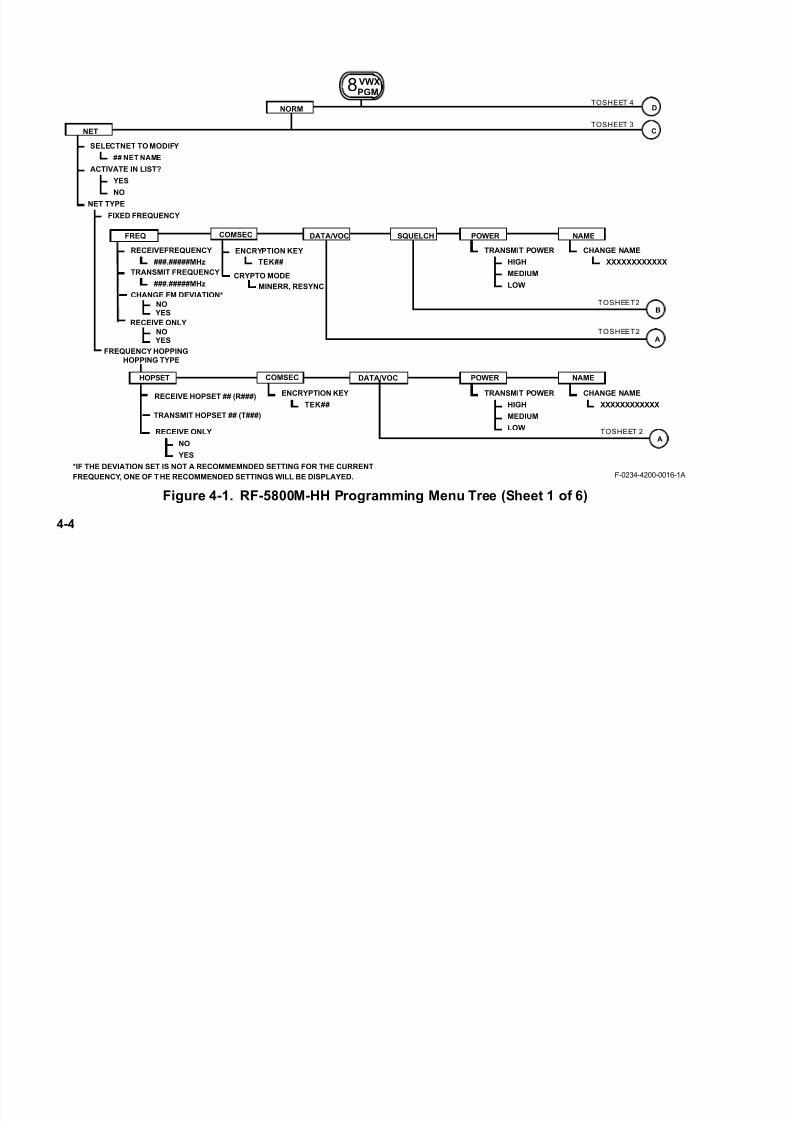
7/21/2019 RF-5800M HH Ops Manual
http://slidepdf.com/reader/full/rf-5800m-hh-ops-manual 94/199
4-4
Figure 4-1. RF-5800M-HH Programming Menu Tree (Sheet 1 of 6)
ACTIVATE IN LIST?
## NET NAME
SELECTNET TO MODIFY
RECEIVEFREQUENCY
###.#####MHz
TRANSMIT FREQUENCY
###.#####MHz
YES
NO
TOSHEET 4
NET TYPE
FIXED FREQUENCY
ENCRYPTION KEY
TEK##
TRANSMIT POWER CHANGE NAME
XXXXXXXXXXXXHIGH
MEDIUM
LOW
TOSHEET 3
FREQUENCY HOPPING
ENCRYPTION KEY
TEK##
TRANSMIT POWER CHANGE NAME
XXXXXXXXXXXXHIGH
MEDIUM
LOW
TOSHEET2
DNORM
NET C
COMSEC DATA/VOC SQUELCH POWER NAME
B
A
TOSHEET2
HOPSET COMSEC DATA/VOC POWER NAME
8VWXPGM
FREQ
CRYPTO MODE
MINERR, RESYNC
RECEIVE HOPSET ## (R###)
TRANSMIT HOPSET ## (T###)
F-0234-4200-0016-1A
RECEIVE ONLY
NO
YES
TOSHEET 2A
HOPPING TYPE
CHANGE FM DEVIATION*
NO YES
RECEIVE ONLY
NO YES
*IF THE DEVIATION SET IS NOT A RECOMMEMNDED SETTING FOR THE CURRENT
FREQUENCY, ONE OF THE RECOMMENDED SETTINGS WILL BE DISPLAYED.

7/21/2019 RF-5800M HH Ops Manual
http://slidepdf.com/reader/full/rf-5800m-hh-ops-manual 95/199
4-5
Figure 4-1. RF-5800M-HH Programming Menu Tree (Sheet 2 of 6)
F-0234-4200-0016-2A
NOTES:
FROM SHEET 1
DIGITAL SQUELCH
B
ON
OFF
FROM SHEET 1
1. NOT AVAILABLE WHEN DATA/VOC TYPE IS SET TO SIMPLE.
2. ONLY AVAILABLE WHEN D/V TYPE IS SET TO SIMPLE.
3. ONLY AVAILABLE WHEN DATA/VOC IS SET TO DATA.
DATA/VOICE
VOICE
DATA OR VOICE (D/V)
DATA
A
D/V TYPE SELECT
SIMPLEWIRELESS IP
DIRECTED
FM DEVIATION (ONLY AVAILABLE IN FM NET)
8.0 kHz
6.5 kHz
5.0 kHz
BAUD RATE (NOTE 2)
16.0 K, 1600, 2666, 8000
(REFER TO APPENDIX B.5.)
(REFER TO APPENDIX B.3.)
ANALOGSQUELCH
OFF
TONE
NOISE
MODULATION (ONLY AVAILABLE IN SIMPLE NET)
FM
AM
WBFSK
ASK
CTCSS (NOTE 2)
ONOFF
CTCSS TONE
VOICE MODE (NOTE 3)
NONE
CVSD

7/21/2019 RF-5800M HH Ops Manual
http://slidepdf.com/reader/full/rf-5800m-hh-ops-manual 96/199
4-6
Figure 4-1. RF-5800M-HH Programming Menu Tree (Sheet 3 of 6)
F-0234-4200-0016-3B
SET HOPSET INCOMPARTENT ##
ENTER HOPSET IDF###
HOPSET TYPE
WIDEBAND
ENTER START FREQ
ENTER STOP FREQ
REVIEW HOPSETIN COMPARTMENT ##
DELETE HOPSETIN COMPARTMENT ##
HOPSETCOMPARTMENTCOPY FROM ##
HOPSETCOMPARTMENT
COPY TO ##
FROM SHEET 1
###.#####MHz
LIST
###.#####MHz
COPY AS HOPSET IDF###
ENC KEY ID##
KEY:
GENERALC
ADD REVIEW DELETE
ENCKEY
DEFINE REVIEW DELETE COPY
ENTER START FREQ.###.##### MHz
ENTER STOP FREQ.###.##### MHz
NAME
RADIO NAME###################
LOCKSET ##/#####.#####-###.#####
LOCKSET ##/#####.#####-###.##### MHz
*****LOCKSET *********DELETED****
******HOPSET *************DELETED******
FREQUENCY ## OF #####.#####
(LIST)
ORHOPSET ##
###.##### - ###.#####(WIDEBAND)
ADD REVIEW
FREQUENCY TO ADD FREQUENCY ## OF ##
###.#####MHz ###.#####MHz
DELETE
*****FREQUENCY ************ADDED******
*****FREQUENCY ************DELETED******
FREQUENCY ## OF #####.##### MHz
LOCKSETHOPSET
HOPPING TYPE
DEFINE
KEY NAME:
KEY TYPE:**
###############
REVIEW
DELETE
TYPE: NAME:
DELETEKEY ##
HOPPING
TYPE: NAME:
YES
NO
**KEY TYPE ONLY VISIBLE WHENCITADEL II IS ENABLED.
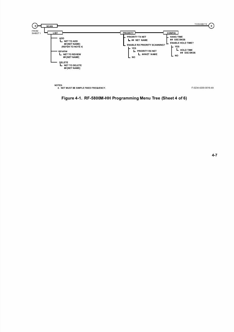
7/21/2019 RF-5800M HH Ops Manual
http://slidepdf.com/reader/full/rf-5800m-hh-ops-manual 97/199
4-7
Figure 4-1. RF-5800M-HH Programming Menu Tree (Sheet 4 of 6)
PRIORITY TX NET
## NET NAME
ENABLE RX PRIORITY SCANNING?
PRIORITY RX NET
YES
NO
##NET NAME
HANG TIME
## SECONDS
ENABLE HOLD TIME?
HOLD TIME
## SECONDS
YES
NO
TOSHEET5
NOTES:
4. NET MUST BE SIMPLE FIXED FREQUENCY.
FROMSHEET1
F-0234-4200-0016-4A
ESCAND
LIST PRIORITY CONFIG
NET TO ADD
## [NET NAME]
ADD
(REFER TO NOTE 4)
NET TO REVIEW
## [NET NAME]
REVIEW
NET TO DELETE
## [NET NAME]
DELETE
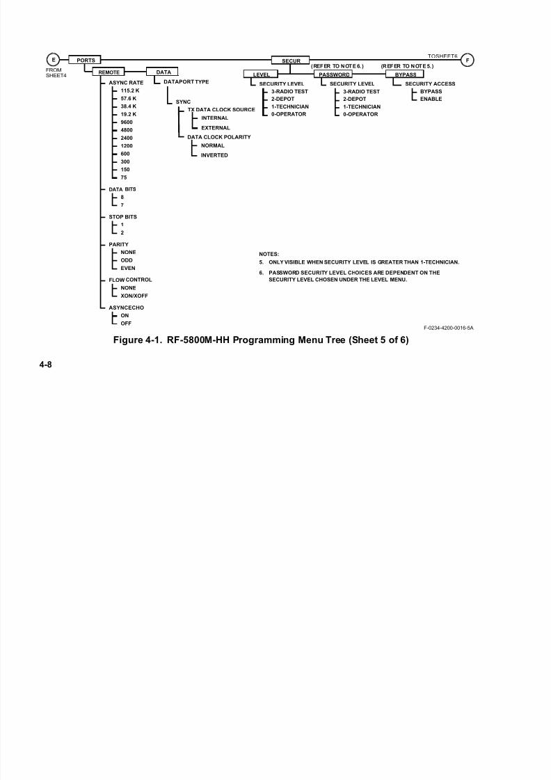
7/21/2019 RF-5800M HH Ops Manual
http://slidepdf.com/reader/full/rf-5800m-hh-ops-manual 98/199
4-8
Figure 4-1. RF-5800M-HH Programming Menu Tree (Sheet 5 of 6)
DATA BITS
8
7
FLOW CONTROL
XON/XOFF
ASYNCECHO
ON
OFF
NONE
FROM
SHEET4
ASYNC RATE
9600
4800
2400
1200
600
300
150
75
19.2 K
57.6 K
38.4 K
115.2 K
DATAPORT TYPE
DATA
PORTS
REMOTE
E
STOP BITS
1
2
PARITY
NONE
ODD
EVEN
SECURITY LEVEL
3-RADIO TEST
2-DEPOT
1-TECHNICIAN
0-OPERATOR
SECURITY LEVEL SECURITY ACCESS
(REFER TO NOTE 6.) (REFER TO NOTE 5.)SECUR
LEVEL PASSWORD BYPASS
BYPASS
ENABLE
F-0234-4200-0016-5A
NOTES:
5. ONLY VISIBLE WHEN SECURITY LEVEL IS GREATER THAN 1-TECHNICIAN.
6. PASSWORD SECURITY LEVEL CHOICES ARE DEPENDENT ON THE
SECURITY LEVEL CHOSEN UNDER THE LEVEL MENU.
TOSHEET6F
3-RADIO TEST
2-DEPOT
1-TECHNICIAN
0-OPERATOR
SYNC
TX DATA CLOCK SOURCE
INTERNAL
EXTERNAL
DATA CLOCK POLARITY
NORMAL
INVERTED

7/21/2019 RF-5800M HH Ops Manual
http://slidepdf.com/reader/full/rf-5800m-hh-ops-manual 99/199
4-9
Figure 4-1. RF-5800M-HH Programming Menu Tree (Sheet 6 of 6)
FROM
SHEET5
EXT_DEV
GPS
F
EXTERNAL 50 W PA MODE
CO-SITE ONCO-SITE OFFBYPASSED
NETWORK
NO
YES
SILENCE BEEPS?
ON
OFF
ROBUST PREAMBLE
ON
OFF
CFIG
GENERAL
POWER MANAGEMENT
ON
OFF
ANC CONNECTOR
DISABLE
ENABLE
SMS
(REFER TO
APPENDIX B.6)
F-0234-4200-0016-6D
CLCK
UTC OFFSET
±00:00
DATE FORMAT
MM-DD-YY
ZULU
YYYY-MM-DDDD-MM-YY
FM TRANSMIT TONE
NEW DATE/TIME
(REFER TO
APPENDIX B.4)
(REFER TO
APPENDIX B.5.)
BEACON
BEACON TYPE
SWEPT
START FREQ (300 - 3200 Hz)STOP FREQ (300 - 3200 Hz)SWEEP RATE (1 - 10 Hz)BEACON FREQUENCY (30 - 512 MHz)BEACON POWER LEVEL (LOW, MED, HIGH)OFF TIME (0 - 100 SECONDS)
TONE
TONE FREQ (300 - 3200 Hz)BEACON FREQ (30 - 512 MHz)BEACON POWER LEVEL (LOW, MED, HIGH)OFF TIME (0 - 100 SECONDS)
ON TIME (1 - 100 SECONDS)
ON TIME (1 - 100 SECONDS)
ALERTS
(REFER TO
APPENDIX B.7)
DC ANTENNA BIAS
OFF
ON
NEW DATE/TIME#### ## ####
NEW TOD##: ##: ##NOTE: IF ANYOTHER DATEFORMAT OTHERTHAN ZULU ISSELECTED, THISMENU OPTIONWILL APPEAR.
LNABYPASS
UHF RECEIVE PATH

7/21/2019 RF-5800M HH Ops Manual
http://slidepdf.com/reader/full/rf-5800m-hh-ops-manual 100/199
4-10
4.4 SECURITY MENU (SECUR)
The RF-5800M-HH provides four levels of security access:
• 0 - OPERATOR - is the default security level for basic radio operators. A radio operator can change radio
nets, enter scan mode, run BITE, and override net parameters. Although the operator can override
parameters such as power level, voice mode, and frequency, these changes cannot be saved. The radio net
parameters will revert back to the programmed settings once the operator changes to a different net.
• 1 - TECHNICIAN - is for radio technicians. At this level, the technician can program radio nets, save
overridden net parameters, program scan list, load keys, and change data and remote port settings.
• 2 - DEPOT - is to be used at the depot level and only adds the ability to BYPASS security access. Refer to
Paragraph 4.4.3 for security access BYPASS information.
• 3 - RADIO TEST - is a radio test level. This allows for low level radio troubleshooting commands to be run.
4.4.1 Level Access
To program the radio's security access level:
a. Press the [PGM] button, then the left/right arrow buttons to select SECUR , and press [ENT].
b. Select LEVEL and press [ENT].
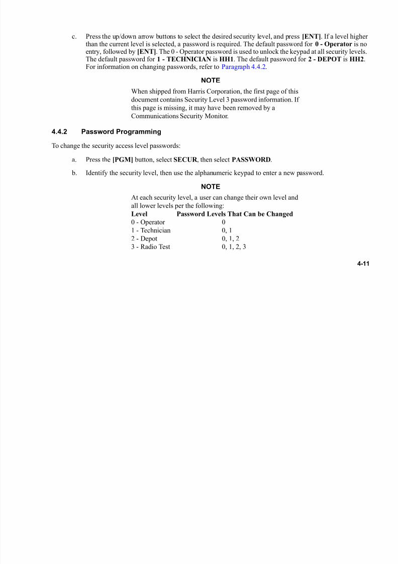
7/21/2019 RF-5800M HH Ops Manual
http://slidepdf.com/reader/full/rf-5800m-hh-ops-manual 101/199
4-11
c. Press the up/down arrow buttons to select the desired security level, and press [ENT]. If a level higherthan the current level is selected, a password is required. The default password for 0 - Operator is noentry, followed by [ENT]. The 0 - Operator password is used to unlock the keypad at all security levels.The default password for 1 - TECHNICIAN is HH1. The default password for 2 - DEPOT is HH2.For information on changing passwords, refer to Paragraph 4.4.2.
NOTE
When shipped from Harris Corporation, the first page of this
document contains Security Level 3 password information. If
this page is missing, it may have been removed by a
Communications Security Monitor.
4.4.2 Password Programming
To change the security access level passwords:
a. Press the [PGM] button, select SECUR , then select PASSWORD.
b. Identify the security level, then use the alphanumeric keypad to enter a new password.
NOTE
At each security level, a user can change their own level and
all lower levels per the following:
Level Password Levels That Can be Changed
0 - Operator 0
1 - Technician 0, 1
2 - Depot 0, 1, 2
3 - Radio Test 0, 1, 2, 3

7/21/2019 RF-5800M HH Ops Manual
http://slidepdf.com/reader/full/rf-5800m-hh-ops-manual 102/199
4-12
A Security Level 1 operator can only change the Security
Level 1or 0 (zero), password. A Security Level 2 or a
Security Level 3 operator can change the Security Level
1 and Security Level 2 passwords.
Zeroizing the radio does not return modified Security Level 1 or Security Level 2 passwords back to the default
passwords. The Security Level 3 password can be changed, but will revert to the factory default when the radio is
zeroized.
4.4.3 BYPASS Programming
2 - DEPOT and 3 - RADIO TEST users can choose to BYPASS security access for lower levels. In BYPASS mode,
all radio commands become available, except for those at 3 - RADIO TEST. To BYPASS security access, press the
[PGM] button, select SECUR , select BYPASS, then change SECURITY ACCESS from ENABLE to BYPASS.
4.5 NORM MENU
To perform NORM programming, press [PGM]. Use the left/right arrow buttons to select NORM and press [ENT].
Two choices are available: GENERAL and NET.
4.5.1 GENERAL Programming
GENERAL programming is used to program radio name, encryption keys, hopsets, and locksets. See Figure 4-1.
For information on NAME programming, refer to Paragraph 4.5.1.1. For information on ENCKEY programming,
refer to Paragraph 4.5.1.2. For information on HOPSET programming, refer to Paragraph 4.5.1.3. For information
on LOCKSET programming, refer to Paragraph 4.5.1.4.
7/21/2019 RF-5800M HH Ops Manual
http://slidepdf.com/reader/full/rf-5800m-hh-ops-manual 103/199
4-13
4.5.1.1 NAME Programming
A specific custom radio name can be assigned that is viewable on the preset screen. Perform the following procedure
to program the radio name:
a. Press [PGM], select NORM and press [ENT].
b. Select GENERAL and press [ENT].
c. Use the left/right arrow buttons to select NAME and press [ENT].
d. Enter a name consisting of up to 16 alphanumeric characters and press [ENT].
4.5.1.2 ENCKEY Programming
An encryption key is a 32-digit hexadecimal number (128-bit for Citadel I/AES-128) or a 64-digit number (256-bit
for Citadel II/AES-256) that the radio's encryption software uses to enable secure Cipher Text (CT) and Advanced
Encryption Standard (AES) with Citadel II communications. Up to 25 encryption keys can be programmed. All
radios communicating on a net must use the same encryption key.
Perform the following procedure to program encryption keys:
a. Press [PGM], select NORM and press [ENT].
b. Select GENERAL and press [ENT].
c. Use the left/right arrow buttons to select ENCKEY and press [ENT].
d. Use the left/right arrow buttons to select DEFINE and press [ENT]. From the same menu screen thatincludes Define, the user can also REVIEW or DELETE existing keys.
e. Enter ENC KEY ID (1 to 25) and press [ENT].

7/21/2019 RF-5800M HH Ops Manual
http://slidepdf.com/reader/full/rf-5800m-hh-ops-manual 104/199
4-14
f. Enter KEY NAME and press [ENT].
g. Enter KEY TYPE and press [ENT].
h. At the KEY prompt enter a 32-digit or 64-digit hexadecimal encryption key number and press [ENT].
4.5.1.3 HOPSET Programming
A hopset consists of a hopset compartment number, a hopset identification (ID) number, and hopset frequency
information. A wideband hopset requires a start frequency and a stop frequency. A list hopset requires a list ofspecific frequencies the net uses for hopping.
NOTE
A maximum of 30 frequencies can be programmed into a list
hopset. The list must contain at least one frequency.
Perform the following procedure to define a hopset:
a. Press [PGM], select NORM and press [ENT].
b. Select GENERAL and press [ENT].
c. Select HOPPING and press [ENT].
d. Select HOPPING TYPE and press [ENT].
e. Use the left/right arrow buttons to select HOPSET and press [ENT].
f. Use the left/right arrow buttons to select DEFINE and press [ENT]. From this screen, the user can alsoREVIEW, DELETE, or COPY existing Hopsets.
g. Enter SET HOPSET IN COMPARTMENT number (1 to 25) and press [ENT].
7/21/2019 RF-5800M HH Ops Manual
http://slidepdf.com/reader/full/rf-5800m-hh-ops-manual 105/199
4-15
h. Enter HOPSET IN (a unique three-digit hopset ID) and press [ENT].
i. Select a HOPSET TYPE of either WIDEBAND or LIST and press [ENT].
1. For wideband hopsets, enter a START FREQ and a STOP FREQ.
2. For list hopsets, ADD individual frequencies. The radio automatically rounds frequencies down
to the nearest 25 kHz. Frequencies must be listed in the same order for all radios in a net.
j. To review a hopset, select REVIEW, under LIST, and enter the hopset's two-digit hopset compartmentnumber.
k. To delete a hopset, select DELETE, under LIST, and enter the hopset's two-digit hopset compartmentnumber.
l. To copy a hopset from one hopset compartment to another compartment, select COPY, enter thetwo-digit hopset compartment number of the hopset to be copied, and enter the compartment numbercopying to and hopset ID of the new hopset being created. Finally, use the DEFINE menu to modifythe new hopset compartment as required.
4.5.1.4 LOCKSET Programming
A lockset, also known as an exclusion band, specifies a range of frequencies that cannot be used during list orwideband frequency hopping. A maximum of 25 locksets can be programmed into the radio. Programmed locksets
apply to all
hopsets. All radios must be programmed with the same locksets.
Perform the following procedure to define a lockset:
a. Press [PGM], select NORM and press [ENT].
b. Select GENERAL and press [ENT].

7/21/2019 RF-5800M HH Ops Manual
http://slidepdf.com/reader/full/rf-5800m-hh-ops-manual 106/199
4-16
c. Select HOPPING and press [ENT].
d. Select HOPPING TYPE and press [ENT].
e. Use the left/right arrow buttons to select LOCKSET and press [ENT].
f. Use the left/right arrow buttons to select ADD and press [ENT].
g. Enter a start frequency at ENTER START FREQ and press [ENT].
h. Enter a stop frequency at ENTER STOP FREQ and press [ENT].
i. To review a lockset, select REVIEW and use the up/down arrow buttons to scroll locksets.
j. To delete a lockset, select DELETE and use the up/down arrow buttons to select lockset to delete. Press[ENT].
4.5.2 Net Programming
NET programming is used to program net presets. See Figure 4-1. For net programming considerations, refer to
Paragraph 4.5.2.1. For information on FIXED FREQUENCY net programming, refer to Paragraph 4.5.2.2. For
information on FREQUENCY HOPPING net programming, refer to Paragraph 4.5.2.3.
4.5.2.1 Net Programming Considerations
Nets have the following characteristics:
• Scan mode allows scanning of a user-defined list of fixed frequency simple net presets.
• Up to 25 net presets can be programmed into each radio (NET0 through NET24).
• A net name can consist of up to 12 alphanumeric characters.

7/21/2019 RF-5800M HH Ops Manual
http://slidepdf.com/reader/full/rf-5800m-hh-ops-manual 107/199
4-17
NOTE
Spaces are not allowed within the net name. The default name
for each net is NET## where ## represents a number from 0
to 24.
• Each net preset may be enabled or disabled during the Activate In List menu function. Enabled net presets
appear in the scrolling list controlled by the [PRE +] or [PRE -] button (when the function switch is in the
FP position). A disabled net is retained in memory but does not appear in the scrolling list.• While in program mode, pressing the [PRE +] or [PRE -] button returns the radio to the last operational
display if the function knob is in the FP position.
• Changing the function knob position causes the radio to exit program mode.
4.5.2.2 Fixed Frequency Net Programming
Perform the following procedure to program a fixed frequency net:
a. Press [PGM], select NORM and press [ENT].
b. Select NET and press [ENT].
c. Use the numeric buttons to enter the number of the net to be programmed, then press [ENT].
d. If ACTIVATE IN LIST? is set to YES, that net is available to the operator. If ACTIVATE IN LIST?is set to NO, that net is not available when the function switch is in FP. Select YES or NO as appropriate.
e. Select FIXED FREQUENCY and press [ENT].
f. Use the left/right arrows to select FREQ and press [ENT]. Enter the receive frequency and press[ENT].
7/21/2019 RF-5800M HH Ops Manual
http://slidepdf.com/reader/full/rf-5800m-hh-ops-manual 108/199
4-18
g. Enter the transmit frequency and press [ENT]. The transmit frequency is automatically set to match thereceive frequency, so it is only necessary to change it if using a half-duplex net.
h. If the radio is to be in radio silence on the net, set RECEIVE ONLY to YES. If the radio is to be ableto transmit on the net, set RECEIVE ONLY to NO. Press [ENT].
i. Use the left/right arrows to select COMSEC and press [ENT]. Enter encryption key number and press[ENT]. Refer to Paragraph 4.5.1.2 for information on programming encryption keys. Select a crypto
mode of either MINERR or RESYNC and press [ENT].• MINERR - This is the default mode. When using MINERR, the start of the transmission must be
heard to receive an encrypted transmission. There is a crypto sync that precedes the waveform.
This mode is supported across all net types: Simple, Directed Calling, and Wireless IP.
• RESYNC - This mode allows a radio on simple voice/data nets (not directed calling or wireless IP
nets) to receive an encrypted transmission already in progress. The radio does not have to hear the
start of the waveform, but can power on and start receiving in mid-transmission. RESYNC is more
susceptible to noise than MINERR.
j. Use the left/right arrows to select DATA/VOC and press [ENT]. Use the up/down arrows to select VOICE, DATA, or DATA OR VOICE (D/V) and press [ENT].
k. Use the up/down arrows to choose SIMPLE for the D/V type and press [ENT]. If Directed Calling orWireless IP operation are to be used, refer to Appendix B. Press [ENT].
l. If DATA was previously selected, choose a VOICE MODE of either NONE or CVSD and press [ENT].
m. Use the up/down arrows to choose a MODULATION type: Frequency Modulation (FM), AmplitudeModulation (AM), Wideband Frequency Shift Keying (WBFSK), and Amplitude Shift Keying (ASK).Available choices are dependant upon which DATA/VOC was selected. Refer to Table 3-2 forDATA/VOC capabilities of each modulation type.

7/21/2019 RF-5800M HH Ops Manual
http://slidepdf.com/reader/full/rf-5800m-hh-ops-manual 109/199
4-19
n. For WBFSK and FM, use up/down arrows to select FM DEVIATION of either 5.0 kHz, 6.5 kHz, or8.0 kHz for analog voice transmissions, and then press [ENT].
o. If Continuous Tone Controlled Squelch System (CTCSS) is to be used, set CTCSS to ON, and press[ENT]. Use the up/down arrows to select the CTCSS tone frequency from the list and press [ENT].
p. If Digital Squelch is desired, use the left/right arrows to select SQUELCH, and then select ON and press [ENT]. If not used, leave the default OFF setting.
q. Use the left/right arrows to select ANALOG SQUELCH TYPE of TONE, NOISE, or OFF. Press[ENT].
r. Use the left/right arrows to select POWER and press [ENT]. Use the up/down arrows to select LOW,MEDIUM, or HIGH transmit power level and press [ENT].
s. Use the left/right arrows to select NAME. The net preset name can be changed from the default NET##to any name, up to 12 characters long. Press [ENT].
4.5.2.3 Frequency Hopping Net Programming
Perform the following procedure to program a frequency hopping net:
a. Press [PGM], select NORM and press [ENT].
b. Select NET and press [ENT]. Refer to Paragraph 4.5.
c. Use the numeric buttons to enter the number of the net to be programmed, then press [ENT].
d. If ACTIVATE IN LIST? is set to YES, that net is available to the operator. If ACTIVATE IN LIST?is set to NO, that net is not available when the function switch is set to off. Nets 1-5 are always availablewhen the function switch is in position 1-5.

7/21/2019 RF-5800M HH Ops Manual
http://slidepdf.com/reader/full/rf-5800m-hh-ops-manual 110/199
4-20
e. Select FREQUENCY HOPPING and press [ENT].
f. Use the left/right arrows to select HOPSET and press [ENT]. Enter the receive hopset compartmentnumber and press [ENT]. Then enter the transmit hopset compartment number and press [ENT]. Forinformation on creating a hopset compartment, refer to Paragraph 4.5.1.3.
g. If the radio is to be in radio silence on the net, set RECEIVE ONLY to YES. If the radio is able totransmit on the net, set RECEIVE ONLY to NO. Press [ENT].
h. Use the left/right arrows to select COMSEC and press [ENT]. Enter encryption key number and press[ENT]. Refer to Paragraph 4.5.1.2 for information on programming encryption keys.
i. Use the left/right arrows to select DATA/VOC and press [ENT]. Use the up/down arrows to select VOICE, DATA, or DATA OR VOICE (D/V) and press [ENT].
j. Use the up/down arrows to choose SIMPLE for the D/V type and press [ENT]. If Directed Calling orWireless IP operation are to be used, refer to Appendix B. Press [ENT].
k. Use the left/right arrows to select POWER and press [ENT]. Use the up/down arrows to select LOW,MEDIUM, or HIGH and press [ENT].
l. Use the left/right arrows to select NAME. The net preset name can be changed from the default NET##
to any name, up to 12 characters long. Press [ENT].
4.6 SCAN MENU
When the radio is in scan mode, only fixed frequency simple radio nets that are programmed into the scan list are
scanned. Up to 25 nets can be programmed in the scan list. Refer to Paragraph 3.14 for information about operating
the radio in scan mode.
7/21/2019 RF-5800M HH Ops Manual
http://slidepdf.com/reader/full/rf-5800m-hh-ops-manual 111/199
4-21
4.6.1 Scan List Programming
Perform the following procedure to program a scan list:
a. Press [PGM] and use the left/right arrows to select SCAN. Press [ENT].
b. Use the left/right arrows to select LIST and press [ENT].
c. Use the left/right arrows to select ADD and press [ENT].
d. Enter a two-digit net number and press [ENT]. Repeat until all desired nets are in list.
e. To review scan list, select REVIEW. Use the up/down arrows to scroll through the scan list.
f. To delete a net from the scan list, select DELETE. Use the up/down arrows to select the net to delete.Press [ENT].
4.6.2 PRIORITY Programming
Once nets are added to the scan list (refer to Paragraph 4.6.1), a priority transmit net and a priority receive net can
be programmed into the radio. The priority transmit net is the net that the radio transmits on if the Push-to-Talk (PTT)
button is pressed when the radio is actively scanning. The radio checks the priority receive net every three nets so
that it is checked more frequently for signal presence than the other nets.
Perform the following procedure to configure transmit and receive priority nets:
a. Press [PGM] and use the left/right arrows to select SCAN. Press [ENT].
b. Use the left/right arrows to select PRIORITY and press [ENT].
c. Use the up/down arrows to scroll to desired PRIORITY TX NET and press [ENT].

7/21/2019 RF-5800M HH Ops Manual
http://slidepdf.com/reader/full/rf-5800m-hh-ops-manual 112/199
4-22
d. The radio prompts: ENABLE RX PRIORITY SCANNING?, YES or NO. If YES is selected, use theup/down arrows to scroll to desired PRIORITY RX NET and press [ENT].
4.6.2.1 CONFIG Programming
Scan CONFIG programming allows the operator to configure the radio's hang time and hold time. Hang time is the
length of time after which the radio returns to automatic scan mode after signal presence is lost on a net. Hold time
is the length of time that the radio, after detecting signal presence on a net, will return to automatic scan mode even
if the signal is still present on that net. If hold time is enabled, the only way to keep the radio from returning toautomatic scan mode is to press either the PTT or CLR buttons.
Perform the following procedure to program scan configuration:
a. Press [PGM], use the left/right arrows to select SCAN, and press [ENT].
b. Use the left/right arrows to select CONFIG and press [ENT].
c. Enter desired HANG TIME (valid range 0 to 99 seconds) duration and press [ENT].
d. At ENABLE HOLD TIME?, use the up/down arrows to select YES or NO. Press [ENT].
e. If YES is selected for enabling hold time, the operator is prompted HOLD TIME. Use the numeric
and/or left/right arrows to input a value (in seconds) between 01 and 99.
4.7 PORTS MENU
The RF-5800M-HH has a side connector that can be used for remote control operations, data devices, external GPS,
or audio operations. Ports programming allows this connector to be configured for these functions. See Figure 4-1.

7/21/2019 RF-5800M HH Ops Manual
http://slidepdf.com/reader/full/rf-5800m-hh-ops-manual 113/199
4-23
4.7.1 REMOTE Port Programming
Perform the following procedure to program the REMOTE port as required by the terminal or computer connected
to the radio:
a. Press [PGM], use the left/right arrows to select PORTS, and press [ENT].
b. Use the left/right arrows to select REMOTE and press [ENT].
c. Use the up/down arrows and press [ENT] to select desired values for the following parameters:
1. ASYNC RATE
2. DATA BITS
3. STOP BITS
4. PARITY
5. FLOW CONTROL
6. ASYNC ECHO
4.7.2 View Data Port Setting
Perform the following procedure to view the DATA port setting:
a. Press [PGM], use the left/right arrows to select PORTS, and press [ENT].
b. Use the left/right arrows to select DATA and press [ENT]. The DATA PORT TYPE will be shown, but is not programmable from this menu. Press [ENT].

7/21/2019 RF-5800M HH Ops Manual
http://slidepdf.com/reader/full/rf-5800m-hh-ops-manual 114/199
4-24
c. When the DATA PORT TYPE is SYNC, the TX DATA CLOCK SOURCE menu will be seen. Usethe up/down arrows to choose INTERNAL or EXTERNAL clock source, and press [ENT].
d. DATA CLOCK POLARITY can be set for NORMAL or INVERTED.
4.8 CFIG MENU
Configuration programming consists of general radio settings, GPS, SMS, Clock settings, Beacon, Network,
external device settings, and Sensor alerts.
4.8.1 GENERAL Settings
Perform the following procedure to configure the general radio settings:
a. Press [PGM], use the left/right arrows to select CFIG, and press [ENT].
b. Select GENERAL and press [ENT].
c. Setting FM TRANSMIT TONE to ON causes the radio to transmit a 150 Hz tone whenever the PTT button is pressed. Select ON or OFF as appropriate.
d. Setting SILENCE BEEPS? to YES prevents the radio from beeping to indicate an operator error.
Select YES or NO as appropriate.
e. Setting ROBUST PREAMBLE to ON causes the radio to transmit extra training frames in CT VOICE.This is required for guaranteed CT SCAN RX to work. Select ON or OFF as appropriate.
f. Setting POWER MANAGEMENT to OFF disables the battery savings modes in your radio. This may be desired to interoperate with legacy equipment. Select ON or OFF as appropriate and press [ENT] when finished.

7/21/2019 RF-5800M HH Ops Manual
http://slidepdf.com/reader/full/rf-5800m-hh-ops-manual 115/199
4-25
g. Setting ANC CONNECTOR to DISABLE causes the 18-pin side connector to be placed in an inactivestate. Refer to Paragraph 4.7 for information about port configuration. The ANC CONNECTOR settingmust be set to ENABLE if programming the radio from RF-6550V VHF-UHF Radio ProgrammingApplication, or if a device such as an external GPS is connected.
CAUTIONCAUTION
If the side connector is not being used, the ANCCONNECTOR setting should be set to DISABLE to remove
the possibility of inadvertently short-circuiting the pins on this
connector.
4.8.2 Programming Beacon Settings
Perform the following procedure to configure the radio’s Beacon settings:
a. Press [PGM], use the left/right arrows to select CFIG, and press [ENT].
b. Use the left/right arrows to select BEACON and press [ENT].
c. Use the up/down arrows to select a BEACON TYPE of either TONE or SWEPT. TONE is a constanttone, and SWEPT is a ramping tone. Press [ENT].
1. If TONE was selected, use the left/right arrows and the numeric buttons to select an audible
frequency for the tone between 300 and 3200 Hz, and the beacon frequency in MHz, and press
[ENT].
2. If SWEPT was selected, use the left/right arrows and the numeric buttons to select an audible
frequency for the start (and stop) frequency (between 300 and 3200 Hz), and press [ENT]. Use the
7/21/2019 RF-5800M HH Ops Manual
http://slidepdf.com/reader/full/rf-5800m-hh-ops-manual 116/199
4-26
left/right arrows and the numeric buttons to select an audio frequency for the stop tone (between
300 and 3200 Hz). Start and stop tones must be different to create a sweep range. Press [ENT].
Use the left/right arrows and the numeric buttons to select a sweep rate (1 to 10 Hz) for the
ramping tone. Press [ENT].
d. Use the left/right arrows and the numeric buttons to enter the Beacon transmitting frequency from 30.0MHz to 512.0 MHz. Press [ENT].
e. Use the left/right arrows to select the Beacon transmitting POWER LEVEL of LOW, MEDIUM, orHIGH. Press [ENT].
NOTE
Beacon power level setting is independent of normal radio
transmit power level settings.
f. Use the left/right arrows and the numeric buttons to select the beacon OFF TIME (000 to 100 seconds).If OFF TIME is set to 000, the Beacon will always be on. Press [ENT].
g. Use the left/right arrows and the numeric buttons to select the beacon ON TIME (001 to 100 seconds).Press [ENT].
NOTE
Settings for Beacon Power Level, Off Time, and On Time, as
well as battery condition, will affect the length of time that the
beacon can transmit effectively. Refer to Paragraph 3.15.2 for
Beacon operation.

7/21/2019 RF-5800M HH Ops Manual
http://slidepdf.com/reader/full/rf-5800m-hh-ops-manual 117/199
4-27
4.8.3 Programming Clock Settings
Perform the following procedure to set the radio’s clock:
a. Press [PGM], use the left/right arrow keys to select CFIG, and press [ENT].
b. Use the left/right arrow keys to select CLCK , and press [ENT].
c. Set UTC OFFSET as required, and press [ENT].
d. Select desired DATE FORMAT and enter the date. Valid entries are: ZULU, YYYY-MM-DD,DD-MM-YY, and MM-DD-YY.
e. If DATE FORMAT of Zulu is selected, the display format will be DDHHMMZ MON YYYY, whereZ is the time zone designator, based upon the Universal Coordinated Time (UTC) Offset setting. If anyother DATE FORMAT is selected, enter the NEW DATE followed by the NEW TOD in the selectedformat.
4.8.4 Programming External Device (EXT_DEV) Settings
Perform the following procedure to configure the radio’s external device settings:
a. Press [PGM], use the left/right arrow keys to select CFIG, and press [ENT].
b. Use the left/right arrow keys to select EXT_DEV and press [ENT].
• Selecting CO-SITE ON switches in additional co-site filtering on the 50 W power amplifier (PA)
• Selecting CO-SITE OFF switches out the additional co-site filtering on the 50 W PA.
• Selecting BYPASSED bypasses the 50 W PA.
7/21/2019 RF-5800M HH Ops Manual
http://slidepdf.com/reader/full/rf-5800m-hh-ops-manual 118/199
4-28
c. The DC ANTENNA BIAS setting is used when connecting an RF-3162-AT001 Dipole antenna. Whenset to ON, a bias voltage (equal to the battery voltage) is applied to the antenna port for the UHFfrequency range 108 MHz to 512 MHz. Whenever the transmit frequency is below 108 MHz (VHFrange), the bias voltage is automatically removed from the antenna port.
4.8.5 Programming RF-6010 Basestation Settings
Refer to Paragraph B.2 for this information.
4.8.6 Programming Situational Awareness Settings
Refer to Paragraph B.4 for this information.
4.8.7 Programming Wireless IP Network Settings
Refer to Paragraph B.5 for this information.
4.8.8 Programming Short Messaging Service Settings
Refer to Paragraph B.6 for this information.
4.8.9 Programming Falcon Watch ™ Sensor Alert Settings
Refer to Paragraph B.7 for this information.

7/21/2019 RF-5800M HH Ops Manual
http://slidepdf.com/reader/full/rf-5800m-hh-ops-manual 119/199
5-1
CHAPTER 5
PREVENTIVE AND CORRECTIVE MAINTENANCE
5.1 PREVENTIVE MAINTENANCE
Optimum performance of the RF-5800M-HH is largely dependent on equipment that receives routine, preventive
maintenance to avoid equipment failures.
Preventive maintenance is the systematic, scheduled care and inspection of equipment to prevent equipment failure
and to reduce downtime.
Preventive maintenance includes keeping the equipment clean, dry, and dust-free.
Use a soft brush, a moist sponge, and a cloth to keep equipment clean.
Table 5-1 contains the checks and services that should be performed either on a daily basis when the equipment is
in use, or on a weekly basis when the equipment is in a standby condition. Table 5-2 contains the checks and services
that should be performed on a weekly basis with the equipment in use.
NOTE
The RF-5800M-HH does NOT require replacement of a
memory Hold Up Battery (HUB).
Table 5-1. Daily Preventive Maintenance Checks and Services
Check No. Item to be Inspected Procedure
1 Operation Perform initial tests as outlined in Paragraph 3.7.
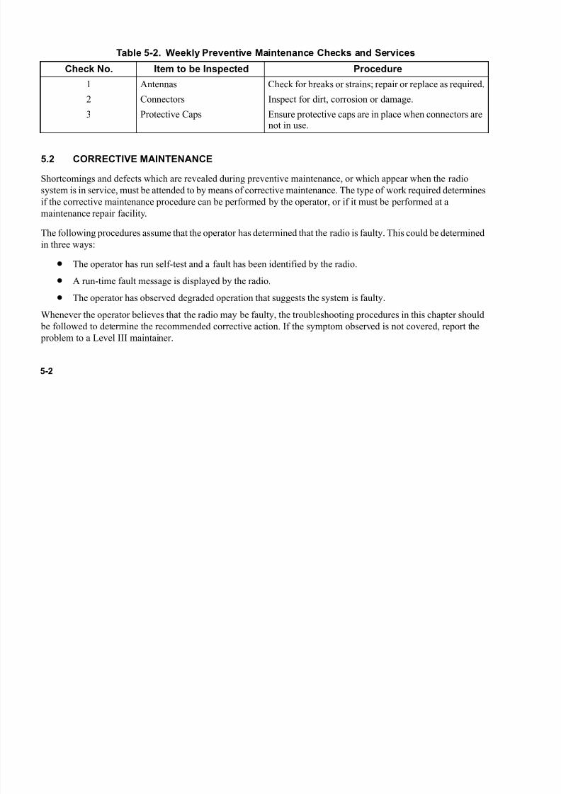
7/21/2019 RF-5800M HH Ops Manual
http://slidepdf.com/reader/full/rf-5800m-hh-ops-manual 120/199
5-2
5.2 CORRECTIVE MAINTENANCE
Shortcomings and defects which are revealed during preventive maintenance, or which appear when the radio
system is in service, must be attended to by means of corrective maintenance. The type of work required determines
if the corrective maintenance procedure can be performed by the operator, or if it must be performed at a
maintenance repair facility.
The following procedures assume that the operator has determined that the radio is faulty. This could be determined
in three ways:
• The operator has run self-test and a fault has been identified by the radio.
• A run-time fault message is displayed by the radio.
• The operator has observed degraded operation that suggests the system is faulty.
Whenever the operator believes that the radio may be faulty, the troubleshooting procedures in this chapter should
be followed to determine the recommended corrective action. If the symptom observed is not covered, report the
problem to a Level III maintainer.
Table 5-2. Weekly Preventive Maintenance Checks and Services
Check No. Item to be Inspected Procedure
1 Antennas Check for breaks or strains; repair or replace as required.
2 Connectors Inspect for dirt, corrosion or damage.
3 Protective Caps Ensure protective caps are in place when connectors arenot in use.

7/21/2019 RF-5800M HH Ops Manual
http://slidepdf.com/reader/full/rf-5800m-hh-ops-manual 121/199
5-3
5.2.1 Troubleshooting Procedures
Faults can be detected by Built-In Test (BIT) or visual observation. Self-test faults are shown on the LCD display.
The following paragraphs identify probable failure causes and suggested corrective actions.
5.2.1.1 BIT Faults
BIT faults occur following an operator-executed self-test. For information on running a radio self-test, refer to
Paragraph 3.7.1.
If the radio displays a fault message, cycle radio power and repeat the self-test. If a fault message is still displayed,
record the fault code, then report the fault to a Level III maintainer.
5.2.1.2 Non-BIT Faults
Non-BIT faults are operator-observed failures, or cases of degraded operation. Locate the observation in the first
column of Table 5-3 and follow the recommended action. If the recommended action is unsuccessful, report the
problem to a Level III maintainer. Refer to Table 5-4 for a list of run-time warnings, their meaning and
recommended action.

7/21/2019 RF-5800M HH Ops Manual
http://slidepdf.com/reader/full/rf-5800m-hh-ops-manual 122/199
5-4
Table 5-3. Non-BIT Troubleshooting
Observation Action
Radio does not power on. Replace battery with a fresh, charged battery. Ifradio still does not power up, send unit tomaintenance.
No Receive (RX)/Transmit (TX) audio; Radio Transmitter
will not key when handset Push-to-Talk (PTT) button is pressed.
Use a different handset (if applicable). Typically,
the handset is used with manpack radios.
Intermittent RX audio. Clean handset connectors. Replace handset (ifapplicable).
Table 5-4. Run-Time Warnings
Warning Message Displayed Description Action
*****FAULT ******SYNTH OUT OF LOCK
RF board is temporarily or permanently rendered incapable ofRX or TX on the currently loaded
frequency.
Cycle radio power. If condition persists, this is a CRITICAL systemfault. Radio needs repair.
******FAULT******GPS COMM FAILURE
Global Positioning System (GPS)communications is not functioningcorrectly. GPS can be set toInternal, External, or None.
Check source of GPS for properoperation.
**CONFIGURATION********CLEARED******
This message indicates the loss of allradio configuration, COMSEC, andTRANSEC data.
Radio must be reprogrammed. Ifcondition persists, radio needsrepair.
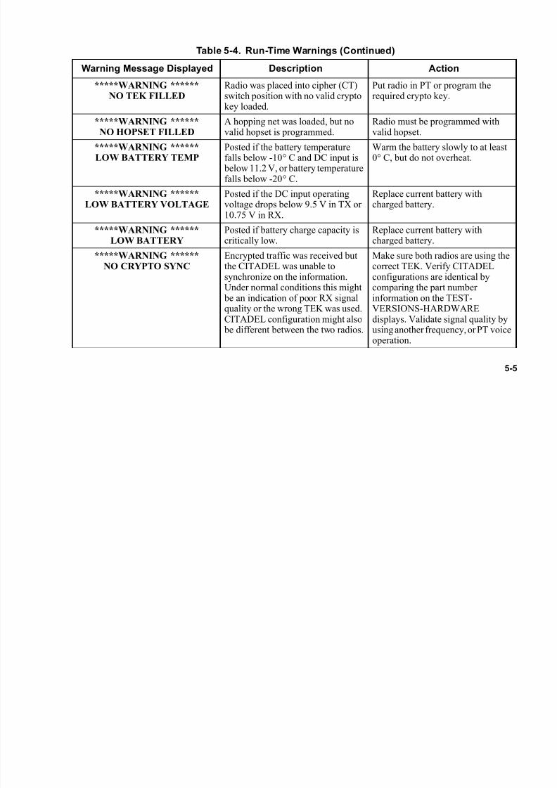
7/21/2019 RF-5800M HH Ops Manual
http://slidepdf.com/reader/full/rf-5800m-hh-ops-manual 123/199
5-5
*****WARNING ******NO TEK FILLED
Radio was placed into cipher (CT)switch position with no valid cryptokey loaded.
Put radio in PT or program therequired crypto key.
*****WARNING ******
NO HOPSET FILLED
A hopping net was loaded, but no
valid hopset is programmed.
Radio must be programmed with
valid hopset.*****WARNING ******LOW BATTERY TEMP
Posted if the battery temperaturefalls below -10° C and DC input is below 11.2 V, or battery temperaturefalls below -20° C.
Warm the battery slowly to at least0° C, but do not overheat.
*****WARNING ******LOW BATTERY VOLTAGE
Posted if the DC input operatingvoltage drops below 9.5 V in TX or10.75 V in RX.
Replace current battery withcharged battery.
*****WARNING ******LOW BATTERY
Posted if battery charge capacity iscritically low.
Replace current battery withcharged battery.
*****WARNING ******
NO CRYPTO SYNC
Encrypted traffic was received but
the CITADEL was unable tosynchronize on the information.Under normal conditions this might be an indication of poor RX signalquality or the wrong TEK was used.CITADEL configuration might also be different between the two radios.
Make sure both radios are using the
correct TEK. Verify CITADELconfigurations are identical bycomparing the part numberinformation on the TEST-VERSIONS-HARDWAREdisplays. Validate signal quality byusing another frequency, or PT voiceoperation.
Table 5-4. Run-Time Warnings (Continued)
Warning Message Displayed Description Action
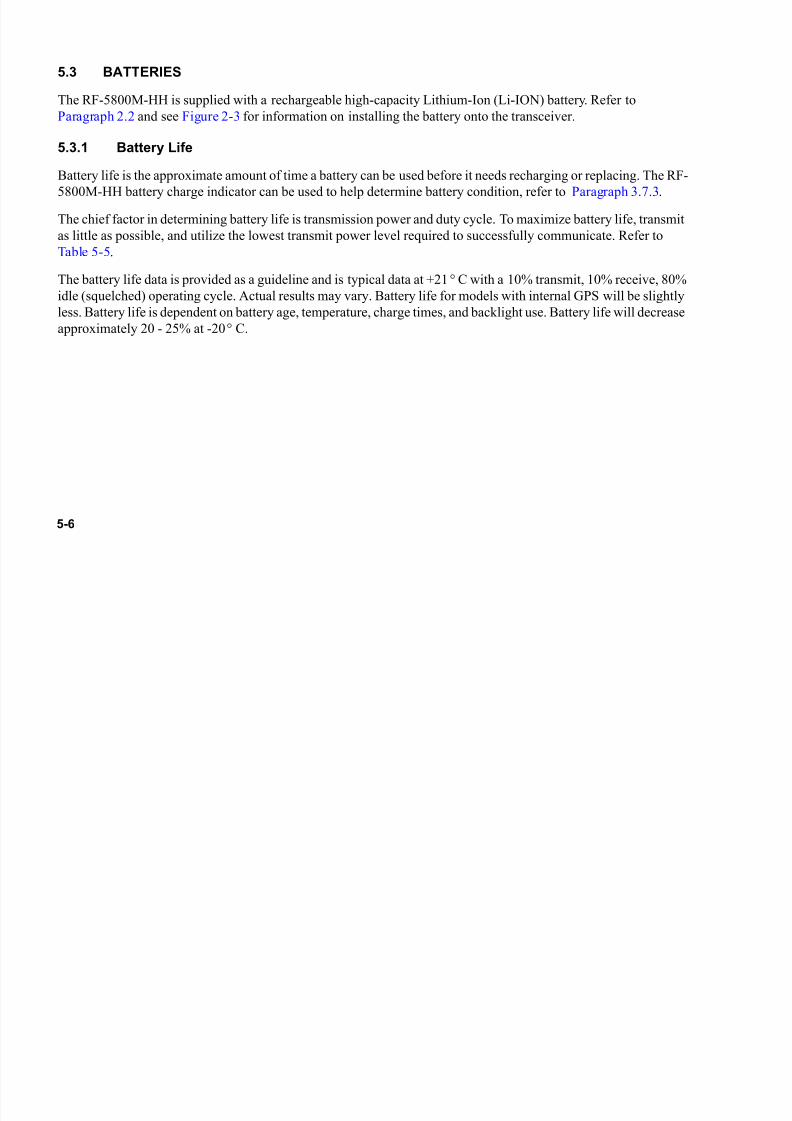
7/21/2019 RF-5800M HH Ops Manual
http://slidepdf.com/reader/full/rf-5800m-hh-ops-manual 124/199
5-6
5.3 BATTERIES
The RF-5800M-HH is supplied with a rechargeable high-capacity Lithium-Ion (Li-ION) battery. Refer to
Paragraph 2.2 and see Figure 2-3 for information on installing the battery onto the transceiver.
5.3.1 Battery Life
Battery life is the approximate amount of time a battery can be used before it needs recharging or replacing. The RF-
5800M-HH battery charge indicator can be used to help determine battery condition, refer to Paragraph 3.7.3.
The chief factor in determining battery life is transmission power and duty cycle. To maximize battery life, transmit
as little as possible, and utilize the lowest transmit power level required to successfully communicate. Refer to
Table 5-5.
The battery life data is provided as a guideline and is typical data at +21° C with a 10% transmit, 10% receive, 80%
idle (squelched) operating cycle. Actual results may vary. Battery life for models with internal GPS will be slightly
less. Battery life is dependent on battery age, temperature, charge times, and backlight use. Battery life will decrease
approximately 20 - 25% at -20° C.
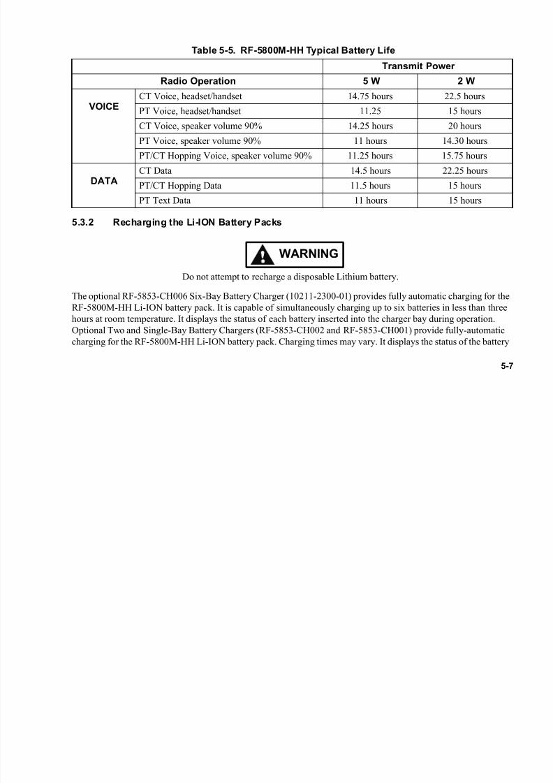
7/21/2019 RF-5800M HH Ops Manual
http://slidepdf.com/reader/full/rf-5800m-hh-ops-manual 125/199
5-7
5.3.2 Recharging the Li-ION Battery Packs
WARNING
Do not attempt to recharge a disposable Lithium battery.
The optional RF-5853-CH006 Six-Bay Battery Charger (10211-2300-01) provides fully automatic charging for the
RF-5800M-HH Li-ION battery pack. It is capable of simultaneously charging up to six batteries in less than three
hours at room temperature. It displays the status of each battery inserted into the charger bay during operation.
Optional Two and Single-Bay Battery Chargers (RF-5853-CH002 and RF-5853-CH001) provide fully-automatic
charging for the RF-5800M-HH Li-ION battery pack. Charging times may vary. It displays the status of the battery
Table 5-5. RF-5800M-HH Typical Battery Life
Transmit Power
Radio Operation 5 W 2 W
VOICECT Voice, headset/handset 14.75 hours 22.5 hours
PT Voice, headset/handset 11.25 15 hours
CT Voice, speaker volume 90% 14.25 hours 20 hours
PT Voice, speaker volume 90% 11 hours 14.30 hours
PT/CT Hopping Voice, speaker volume 90% 11.25 hours 15.75 hours
DATACT Data 14.5 hours 22.25 hours
PT/CT Hopping Data 11.5 hours 15 hours
PT Text Data 11 hours 15 hours

7/21/2019 RF-5800M HH Ops Manual
http://slidepdf.com/reader/full/rf-5800m-hh-ops-manual 126/199
5-8
pack when inserted into the charger bay during operation. A separate manufacturer's battery charger manual is
supplied with each battery charger.
5.3.3 Disposing of Li-ION Batteries
WARNING
Do not dispose of Li-ION batteries in uncontrolled trash.
Completely discharge batteries before proper disposal. Partially discharged batteries may contain a significant
amount of energy and should be handled with care. The battery pack should be wrapped with insulating material,
such as plastic, and packed for disposal.
WARNING
Do not crush, disassemble, reverse polarity, incinerate, or
mutilate the lithium-ion battery. Do not expose to fire or
temperatures above 160° F (71° C).

7/21/2019 RF-5800M HH Ops Manual
http://slidepdf.com/reader/full/rf-5800m-hh-ops-manual 127/199
5-9
5.3.4 Battery Storage and Maintenance
For maximum battery life, observe the following:
• It is not necessary to wait until the battery is completely discharged before recharging the battery.
• Keep the battery's metal contacts clean.
• Replace the battery when it no longer provides acceptable performance. The battery can be recharged
several hundred times before requiring replacement.
• Store unused batteries in a cool, dry place.
• Recharge the battery after long periods of non-use (six months) to maximize battery life.
• The RF-5800M-HH monitors the absolute state of charge of the battery. Refer to Paragraph 3.7.3 for a
complete description.

7/21/2019 RF-5800M HH Ops Manual
http://slidepdf.com/reader/full/rf-5800m-hh-ops-manual 128/199
5-10
This page intentionally left blank.
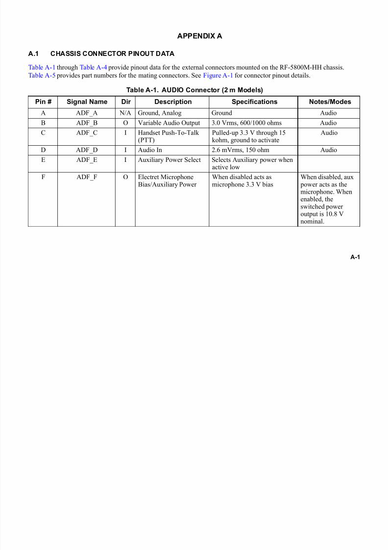
7/21/2019 RF-5800M HH Ops Manual
http://slidepdf.com/reader/full/rf-5800m-hh-ops-manual 129/199
A-1
APPENDIX A
A.1 CHASSIS CONNECTOR PINOUT DATA
Table A-1 through Table A-4 provide pinout data for the external connectors mounted on the RF-5800M-HH chassis.
Table A-5 provides part numbers for the mating connectors. See Figure A-1 for connector pinout details.
Table A-1. AUDIO Connector (2 m Models)
Pin # Signal Name Dir Description Specifications Notes/Modes
A ADF_A N/A Ground, Analog Ground Audio
B ADF_B O Variable Audio Output 3.0 Vrms, 600/1000 ohms Audio
C ADF_C I Handset Push-To-Talk(PTT)
Pulled-up 3.3 V through 15kohm, ground to activate
Audio
D ADF_D I Audio In 2.6 mVrms, 150 ohm Audio
E ADF_E I Auxiliary Power Select Selects Auxiliary power whenactive low
F ADF_F O Electret MicrophoneBias/Auxiliary Power
When disabled acts asmicrophone 3.3 V bias
When disabled, aux power acts as themicrophone. Whenenabled, theswitched poweroutput is 10.8 Vnominal.
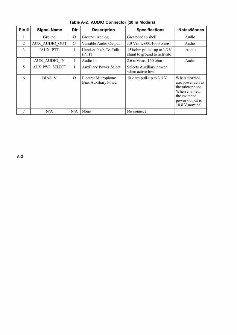
7/21/2019 RF-5800M HH Ops Manual
http://slidepdf.com/reader/full/rf-5800m-hh-ops-manual 130/199
A-2
Table A-2. AUDIO Connector (20 m Models)
Pin # Signal Name Dir Description Specifications Notes/Modes
1 Ground O Ground, Analog Grounded to shell Audio
2 AUX_AUDIO_OUT O Variable Audio Output 3.0 Vrms, 600/1000 ohms Audio
3 /AUX_PTT I Handset Push-To-Talk(PTT)
15 kohm pulled-up to 3.3 Vshunt to ground to activate
Audio
4 AUX_AUDIO_IN I Audio In 2.6 mVrms, 150 ohm Audio
5 AUX_PWR_SELECT I Auxiliary Power Select Selects Auxiliary powerwhen active low
6 BIAS_V O Electret MicrophoneBias/Auxiliary Power
1k ohm pull-up to 3.3 V When disabled,aux power acts asthe microphone.When enabled,the switched power output is10.8 V nominal.
7 N/A N/A None No connect

7/21/2019 RF-5800M HH Ops Manual
http://slidepdf.com/reader/full/rf-5800m-hh-ops-manual 131/199
A-3
Table A-3. Side Connector Pinouts
Pin # Signal Name Dir Description SpecificationsNotes/
Modes
1 ANC_SIG_GND Signal Ground
2 ANC_AUDIO_OUT O Auxiliary Audio Output(Optional)
H-250 Compatible Test,Retransmit
3 RETRANS O Retransmit OutActive low
Open Drain (15 V max, 20 mAmax, 115 ohm sink)
Retransmit
4 NC No Connect Reserved
5 ANC_PTT I Auxiliary Audio Keyline H-250 Compatible Test,Retransmit
6 ANC_RT_OFF I Overrides On/Off Switch Test
7 ANC_DAT_DCD O Data Carrier Detect RS-232/MIL-STD-188-114A Data Port
8 ANC_DAT_RTS I Request To Send RS-232/MIL-STD-188-114A Data Port
9 ANC_AUDIO_IN I Auxiliary Audio Input 0 dBm nominal Test,Retransmit
10 ANC_DAT_RXC O Synchronous ReceiveData Clock
RS-232/MIL-STD-188-114A Data Port
11 ANC_DAT_TXD I Transmit Data RS-232/MIL-STD-188-114A Data Port
12 ANC_DAT_RXD O Receive Data RS-232/MIL-STD-188-114A Data Port
13 ANC_RMT_RXD I Remote Control ReceiveData
RS-232/MIL-STD-188-114A Remote Port

7/21/2019 RF-5800M HH Ops Manual
http://slidepdf.com/reader/full/rf-5800m-hh-ops-manual 132/199
A-4
14 CABLE_PRES I Cable Sense No connecton 4200 board
15 ANC_RMT_TXD O Remote Control TransmitData
RS-232/MIL-STD-188-114A Remote Port
16 ANC_PWR O 9.3 - 14 VDC ExternalPower Supply (Switched)
30 mA @ 60 C Eng use only
17 ANC_DAT_CTS O Clear-To-Send RS-232/MIL-STD-188-114A Data Port
18 ANC_DAT_TXC I Synchronous TransmitData Clock
RS-232/MIL-STD-188-114A Data Port
Table A-4. VHF-UHF ANTENNA Connector
Pin # Signal Name Dir Description Specs Notes/Modes
Shield Antenna CoaxGround
N/A Ground
Center RX/TX RF I/O Receive and transmitsignal
TX: 5 wattsmax
Table A-3. Side Connector Pinouts (Continued)
Pin # Signal Name Dir Description SpecificationsNotes/
Modes

7/21/2019 RF-5800M HH Ops Manual
http://slidepdf.com/reader/full/rf-5800m-hh-ops-manual 133/199
A-5
Table A-5. 2 M and 20 M Connectors and Mating Connector Part Numbers
Radio Chassis Connector Connector
Part Number
6-Pin Audio J69-0001-623
7-Pin Audio J40-0023-007
Side Connector 12011-9020-01
Figure A-1. Radio Connector Pinouts
A
B
CD
E
F
6-PIN AUDIO (2 M) SIDE CONNECTOR
1 3
F-0234-4200-017
7-PIN AUDIO (20 M)
1 2
3
45
67
16 18

7/21/2019 RF-5800M HH Ops Manual
http://slidepdf.com/reader/full/rf-5800m-hh-ops-manual 134/199
A-6
This page intentionally left blank.
7/21/2019 RF-5800M HH Ops Manual
http://slidepdf.com/reader/full/rf-5800m-hh-ops-manual 135/199
B-1
APPENDIX B
ADVANCED FEATURES
B.1 INTRODUCTION
This appendix describes advanced features of the RF-5800M-HH. See Figure B-1 for the programming menu of these
advanced features. Refer to Figure 4-1 for other basic programming menus.
• RF-6010 Basestation Support - Paragraph B.2
• Directed Calling - Paragraph B.3
• Situational Awareness - Paragraph B.4
• Wireless Internet Protocol (IP) Network - Paragraph B.5
• Short Messaging Service (SMS) - Paragraph B.6
• Falcon Watch™ Sensor Alerts - Paragraph B.7

7/21/2019 RF-5800M HH Ops Manual
http://slidepdf.com/reader/full/rf-5800m-hh-ops-manual 136/199
B-2
Figure B-1. Advanced Features Programming Menu (Sheet 1 of 3)
F-0234-4200-0018-2
ACTIVATE IN LIST?
## NET NAME
SELECT NET TO MODIFY
YES
NO
NET TYPE
FIXED FREQUENCY
NORM
NET
DATA/VOC
8VWXPGM
DATA/VOICE
VOICE
DATA
DATA OR VOICE (D/V)
D/V TYPE SELECT
WIRELESS IP
RADIO ADDRESS:###
NETWORK ADDRESS:###.###.###.###
DEFAULT GATEWAY###
NETWORK TOPOLOGY
MESH
EXCLUSIVE
POINT
RADIO ADDRESS:###
DEFAULT GATEWAY:###
DIRECTED
FM DEVIATION
8.0 kHz
6.5 kHz
5.0 kHz
NOTES:
1. NOT VISIBLE IN A SIMPLE NET.
DATA/VOICE SELECTIONS AFFECT WHAT OPTIONS ARE AVAILABLE FOR SIMPLE MODULATION.
TOSHEET2B
MODULATION
SIMPLE
FM
AM
BAUD RATE (REFER TO NOTE 1)
16.0 K, 1600, 2666, 8000
ORFREQUENCY HOPPING
ASKWBFSK CTCSS (REFER TO NOTE 1)
ON
OFF
CTCSS TONE
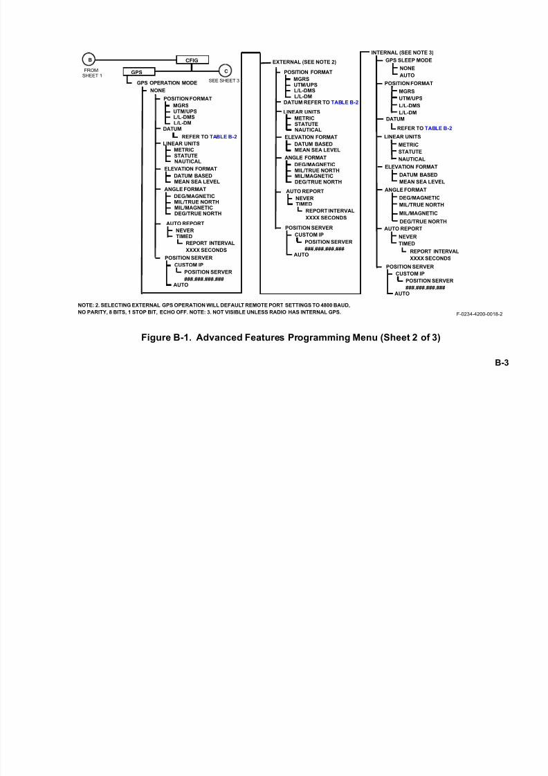
7/21/2019 RF-5800M HH Ops Manual
http://slidepdf.com/reader/full/rf-5800m-hh-ops-manual 137/199
B-3
Figure B-1. Advanced Features Programming Menu (Sheet 2 of 3)
F-0234-4200-0018-2
CFIG
GPS
GPS OPERATION MODE
NONE
EXTERNAL (SEE NOTE 2)
POSITION FORMAT
MGRSUTM/UPSL/L-DMSL/L-DM
LINEAR UNITS
METRICSTATUTENAUTICAL
ELEVATION FORMAT
DATUM BASEDMEAN SEA LEVEL
ANGLE FORMAT
DEG/MAGNETICMIL/TRUE NORTHMIL/MAGNETICDEG/TRUE NORTH
AUTO REPORT
NEVERTIMED
REPORT INTERVAL
XXXX SECONDS
POSITION SERVER
CUSTOM IP
AUTO
POSITION SERVER
###.###.###.###
FROM
SHEET 1
B
C
INTERNAL (SEE NOTE 3)
GPS SLEEP MODE
NONE
DATUM
AUTO
POSITION FORMAT
MGRS
UTM/UPS
L/L-DMS
L/L-DM
REFER TO TABLE B-2
LINEAR UNITS
METRIC
STATUTE
NAUTICAL
ELEVATION FORMAT
DATUM BASED
MEAN SEA LEVEL
ANGLE FORMAT
DEG/MAGNETIC
MIL/TRUE NORTH
MIL/MAGNETIC
DEG/TRUE NORTH
AUTO REPORT
NEVER
TIMED
SEE SHEET 3
DATUM
POSITION FORMAT
MGRSUTM/UPSL/L-DMSL/L-DM
LINEAR UNITS
METRICSTATUTE
NAUTICALELEVATION FORMAT
DATUM BASEDMEAN SEA LEVEL
ANGLE FORMAT
DEG/MAGNETICMIL/TRUE NORTHMIL/MAGNETICDEG/TRUE NORTH
DATUM REFER TO TABLE B-2
REFER TO TABLE B-2
NOTE: 2. SELECTING EXTERNAL GPS OPERATION WILL DEFAULT REMOTE PORT SETTINGS TO 4800 BAUD,
NO PARITY, 8 BITS, 1 STOP BIT, ECHO OFF. NOTE: 3. NOT VISIBLE UNLESS RADIO HAS INTERNAL GPS.
AUTO REPORT
NEVERTIMED
REPORT INTERVAL
XXXX SECONDS
POSITION SERVER
CUSTOM IP
AUTO
POSITION SERVER
###.###.###.###
POSITION SERVER
CUSTOM IP
AUTO
POSITION SERVER
###.###.###.###
REPORT INTERVAL
XXXX SECONDS

7/21/2019 RF-5800M HH Ops Manual
http://slidepdf.com/reader/full/rf-5800m-hh-ops-manual 138/199
B-4
Figure B-1. Advanced Features Programming Menu (Sheet 3 of 3)
NETWORK
PPP
ENABLE PPP PORTNO
YES
IP ADDRESS###.###.###.###
PEER IP ADDRESS
AUTO SETTING IS NOTPROGRAMMABLE
NEGOTIATED IP ADDR###.###.###.###
NEGOTIATED PEER IP###.###.###.###
SETTING IS NOT
PROGRAMMABLE
SETTING IS NOT
PROGRAMMABLE
DATA RATE
115.2 K57.6 K38.4 K19.2 K
C
FROM SHEET
SMS CLCK EXT_DEV
EXTERNAL 50 WPA MODE
CO-SITE ONCO-SITE OFFBYPASSED
REFER TO
PARAGRAPH 4.8.3
CANNED
1-10
SETTINGS
INSERT
TEXT ENTRYMODE
OVERWRITE
ON
TEXT PREDICTION
OFF
ON
TONE ALERT
OFF
ON
CAP MODE
OFF
ON
ACKNOWLEDGE
OFF
F-185-4200-0018-3B
EDIT
DELETE
DELETE ALL
2
STATUS
BAUD
ADDRESS
ALERTS
ON
ALERTS ENABLE
OFF
ON
ALERT DISPLAY
OFF
ON
ALERT TONE
OFF
DC ANTENNA BIAS
OFF
ON
UHF RECEIVE PATH
BYPASS
LNA
7/21/2019 RF-5800M HH Ops Manual
http://slidepdf.com/reader/full/rf-5800m-hh-ops-manual 139/199
B-5
B.2 RF-6010 BASESTATION
The RF-5800M-HH radio supports a direct Point-to-Point Protocol (PPP) connection to the Harris RF-6010
Basestation for telephony and IP data communications. The RF-5800M-HH can be used as an outstation to perform
telephony calls to the RF-6010 Basestation. Wireless networking capability and telephony capability are provided
for radios that support wireless Internet Protocol (IP) functionality. Telephony capability requires use of the Harris
RF-6010 Tactical Network Access Hub and associated peripheral equipment.
RF-5800M-HH radios directly connected to the RF-6010 can be programmed through the RF-6010. The RF-6010must be programmed using the RF-6010 Programming Application prior to programming the base radios.
The RF-5800M-HH radio supports:
• Ability to transmit and receive voice/data to and from the RF-6010 Basestation.
• Phone-to-phone communications through the RF-6010 Basestation.
• Operation of RF-6010 similar to Directed Calling when configured as a telephony gateway.
• Computer Telephony Interface (CTI) calls when configured as a RF-6010 Basestation.
• Harris Session Initiation Protocol (HSIP) V2.0.
For more information, refer to the RF-6010NW-001 Tactical Network Access Hub User Manual, Harris Publication Number (10515-0262-4200). See Figure B-3 for an example of a telephony network.
7/21/2019 RF-5800M HH Ops Manual
http://slidepdf.com/reader/full/rf-5800m-hh-ops-manual 140/199
B-6
B.3 DIRECTED CALLING
The following contains information and programming instructions for Directed Calling.
B.3.1 Description
The Directed Calling feature allows a radio operator to hold a private voice conversation with another radio in the
net. The call may be performed in either fixed frequency or frequency hopping. Calls support Plain Text (PT) and
Cipher Text (CT) in Voice (VOC), or Data/Voice (D/V).
Directed Calls create a virtual circuit by reserving a channel. A channel is defined as a fixed frequency or a set of
hop frequencies. Channel reservation informs other radios on the net that the channel is occupied. This indication
appears on the front panel of the excluded radios as a BUSY-VOICE status message.
Radios in the net that are excluded from the directed call are not able to hear or participate in the conversation.
Although these radios may not participate in the call, they have the ability to break-in on a directed call. This is a
transmit-only function, intended for emergency use to alert the participants. The radios in the directed call can hear
the incoming message, but the radio outside the call will still not be able to listen in. The break-in radio will not hear
a response from the directed call radios until the virtual circuit is released.
If the channel is actively participating in a directed call, radios not participating in it have the ability to request a
directed call. The request is placed in a queue and waits for the channel to be freed for use. If the channel does not
free up after 20 seconds, the radio will display CALL FAILED: NO RESPONSE.
After a transmission has completed on the circuit, the radio inactivity timer is started. If there has been no activity
on a directed call circuit for 20 seconds, the circuit will be terminated. Since channel reservation and release consists
of special signaling that uses a handshake mechanism to establish and tear down virtual circuits, only radios on nets
that have a programmed radio identification (ID) may utilize this feature.

7/21/2019 RF-5800M HH Ops Manual
http://slidepdf.com/reader/full/rf-5800m-hh-ops-manual 141/199
B-7
A radio operator initiating a directed call is presented with the option of using either a station name or radio ID. A
station name is an easy to remember name that associates radio IDs with particular radio nets. The Very High
Frequency - Ultra High Frequency (VHF-UHF) Radio Programming Application (RPA) can be used to preload a list
of up to 50 radio stations into the radio.
NOTE
If no stations have been programmed by the VHF-UHF RPA,
or no stations have radio IDs associated with the current radionet, then the operator will only be presented with the option of
using a radio ID to make a call.
If the current radio net supports directed calling, then the radio’s ID is displayed on the top line to the right of the
battery status bar. If the current net does not support directed calling, then NORM is displayed. When a directed call
has been established, either the station name (if one has been programmed) or radio ID of their other party is
displayed on the bottom line of the display.
B.3.2 Initiating a Directed Call Using a Radio ID
The Directed Calling feature allows a radio user to establish a private voice call between two radios. Only the two
radios participating in the call will hear the audio. Perform the following to make a direct call using a radio ID:
a. From the main menu, press the [CALL] button.
b. If default gateway is programmed for RF-6010, use the up/down arrow keys to select RADIO forCALL TYPE and press [ENT].
c. Select the ADDRESS TYPE and press [ENT].
d. If radio names are programmed, use the up/down arrow keys to select RADIO ID and press [ENT].

7/21/2019 RF-5800M HH Ops Manual
http://slidepdf.com/reader/full/rf-5800m-hh-ops-manual 142/199
B-8
e. Use the keypad to enter the three-digit RADIO ID (001 - 254) to be called, and press [ENT].
f. The radio initiates a call and establishes a circuit to a particular radio ID.
g. The radio is linked to another radio. The radio ID of the other radio in the directed call is displayed atthe bottom of the screen.
B.3.2.1 Terminating a Directed Call
The radio operator can terminate a directed call at any time. Perform the following to terminate a directed call usinga station name:
a. With a directed call in process, press the [CLR] key.
b. Use the up/down arrows to select YES, then press [ENT] to terminate the link. After a few seconds, thescreen will change to the main menu.
B.3.2.2 Breaking into a Directed Call
When a channel is reserved (directed call in process), radios not participating in the directed call will not be able to
transmit on the net. If the Push-To-Talk (PTT) button is pressed, the operator is notified that the radio cannot transmit
by emitting a tone and displaying a BUSY status on the main screen.
To break into the directed call, an operator can hold down the PTT button for five (5) seconds. During this time, the
radio will emit a busy tone to indicate that it is not transmitting. The radio will then break in and begin to transmit
once the busy tone stops. The privacy of the directed call is still maintained since the operator breaking in cannot
hear the directed call participants.
If the PTT button is released after the radio has broken into the directed call, the complete break-in process needs to
be repeated for the radio to transmit over the reserved channel again.

7/21/2019 RF-5800M HH Ops Manual
http://slidepdf.com/reader/full/rf-5800m-hh-ops-manual 143/199
B-9
B.3.2.3 Busy State
A radio that is excluded from a directed call cannot transmit/receive messages on the net until the call is terminated.
The radio operator has the choice to wait for the directed call to terminate, utilize the directed call queue, or break
into the directed call. If the operator presses the PTT button, the radio will warn the operator that it cannot transmit
by emitting a tone. For the radios that are excluded from the directed call, BUSY-VOICE appears on the Liquid
Crystal Display (LCD).
B.3.2.4 Radio Call Inactivity Timer
If the PTT button has not been keyed and no traffic has been received on a directed call for a period of 20 seconds,
the call is terminated due to a timeout.
B.3.3 Directed Calling Programming
This section describes programming the Directed Calling feature from the radio front panel. Refer to Chapter 4 for
general radio programming.
B.3.3.1 Net Programming
A radio net is defined as a group of radios that share common communication parameters, such as frequencies, data
and voice types, etc. Net programming in the RF-5800M-HH consists of all the data that describes a radio netincluding name, frequency, data/voice settings, squelch, transmit power, etc.
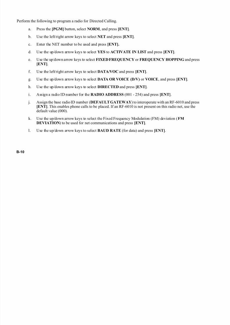
7/21/2019 RF-5800M HH Ops Manual
http://slidepdf.com/reader/full/rf-5800m-hh-ops-manual 144/199
B-10
Perform the following to program a radio for Directed Calling.
a. Press the [PGM] button, select NORM, and press [ENT].
b. Use the left/right arrow keys to select NET and press [ENT].
c. Enter the NET number to be used and press [ENT].
d. Use the up/down arrow keys to select YES to ACTIVATE IN LIST and press [ENT].
e. Use the up/down arrow keys to select FIXED FREQUENCY or FREQUENCY HOPPING and press[ENT].
f. Use the left/right arrow keys to select DATA/VOC and press [ENT].
g. Use the up/down arrow keys to select DATA OR VOICE (D/V) or VOICE, and press [ENT].
h. Use the up/down arrow keys to select DIRECTED and press [ENT].
i. Assign a radio ID number for the RADIO ADDRESS (001 - 254) and press [ENT].
j. Assign the base radio ID number (DEFAULT GATEWAY) to interoperate with an RF-6010 and press[ENT]. This enables phone calls to be placed. If an RF-6010 is not present on this radio net, use the
default value (000).
k. Use the up/down arrow keys to select the Fixed Frequency Modulation (FM) deviation (FMDEVIATION) to be used for net communications and press [ENT].
l. Use the up/down arrow keys to select BAUD RATE (for data) and press [ENT].

7/21/2019 RF-5800M HH Ops Manual
http://slidepdf.com/reader/full/rf-5800m-hh-ops-manual 145/199
B-11
B.3.4 Error Messages and Corrective Actions
Table B-1 shows error messages and corrective actions that may be encountered during directed calling. It is
assumed that the radio has been programmed correctly and this is not the reason for the error. When in doubt, verify
that the programmed parameters are valid.
Table B-1. Error Messages and Corrective Actions
Fault Message Corrective ActionCALL FAILED
NO RESPONSE
PRESS CLR/ENT TO CLEAR
The targeted radio is not listening on the current frequency,is currently in a circuit, is in a different operating state, or poor signal strength has caused the radio to miss the over-the-air signaling. Place the call again.

7/21/2019 RF-5800M HH Ops Manual
http://slidepdf.com/reader/full/rf-5800m-hh-ops-manual 146/199
B-12
B.4 SITUATIONAL AWARENESS (SA)
The following contains information and programming instructions for Situational Awareness (SA) in the
RF-5800M-HH.
B.4.1 Description
Situational Awareness (SA) is the ability to provide remote sites with information about a radio’s geographical
position. This positioning information is provided via the Global Positioning System (GPS). The remote sites may be radios or sophisticated applications running on PCs.
Situational Awareness reports can be sent via fixed frequency or frequency hopping. The RF-5800M-HH can use
either the optional internal GPS module or an external GPS device to read the position, and then the information can
be transmitted to a remote site.
NOTE
The radio operator can send a position report to any remote net
location, however, the net must be set up for Directed Calling
and operating in Cipher Text (CT).
RF-5800M-HH radio operators can view their own current position, and store/view other remote station positions.When a radio receives a remote station’s position, it will automatically store the location in memory. The radio can
calculate the distance and bearing of each remote station relative to its own current position. The radio will store up
to 50 remote station positions, however, the stored locations are not saved when the radio is turned off.

7/21/2019 RF-5800M HH Ops Manual
http://slidepdf.com/reader/full/rf-5800m-hh-ops-manual 147/199
B-13
NOTE
Maximum communications range can be achieved when
interfering devices are kept at a distance from the radio.
Therefore, it is recommended that the external GPS receiver
be turned off and disconnected from the radio when it is not
required to send a position report.
B.4.2 SA Features
The user can select the format of the reported position information using the RF-5800M-HH front panel menus.
• Position Format: This setting determines how position information is displayed. Selections include Military
Grid Reference System (MGRS), Universal Transverse Mercator/Universal Polar Stereographic
(UTM/UPS), Latitude/Longitude-degree, minute, second (L/L-dms), Latitude/Longitude-degree, minute
(L/L-dm).
• Linear Units Format: The radio operator can select the units of altitude and velocity displays. Selections
include Nautical (feet, knots), Metric (meters, kilometers per hour), or Statute (feet, miles per hour).
• Elevation Format: The operator can control whether altitude is based on Mean Sea Level or the currently
selected datum.
• Angle Format: The radio operator can control the heading display. Selections are:
• DEG/TRUE NORTH (degrees referenced to true north)
• DEG/MAGNETIC (degrees referenced to magnetic north)
• MIL/TRUE NORTH (mils referenced to true north)
• MIL/MAGNETIC (mils referenced to magnetic north)
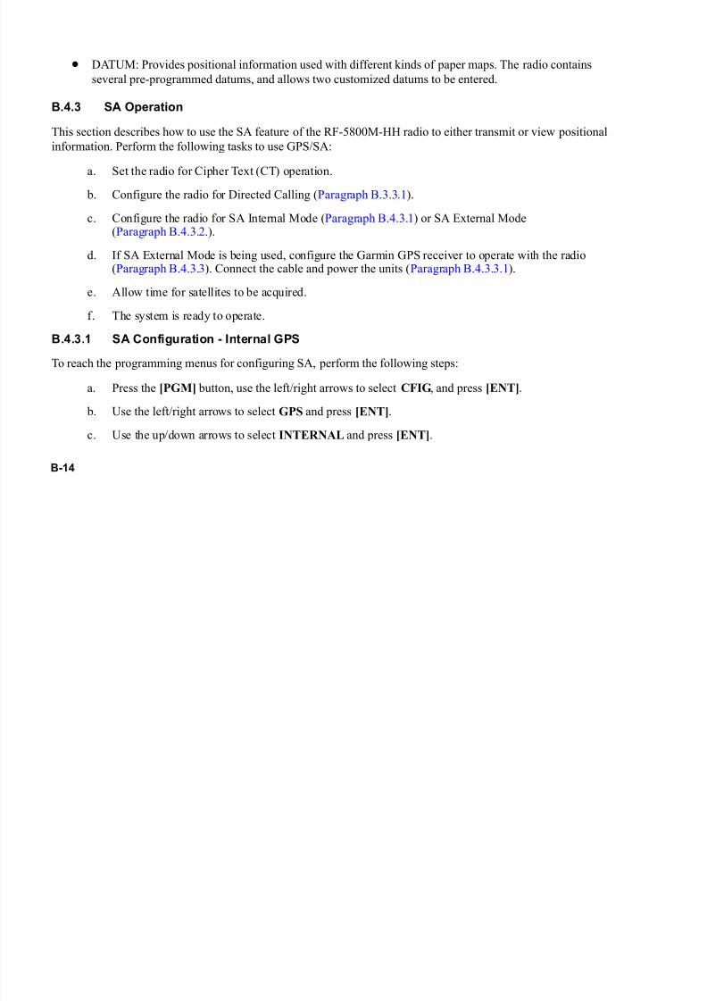
7/21/2019 RF-5800M HH Ops Manual
http://slidepdf.com/reader/full/rf-5800m-hh-ops-manual 148/199
B-14
• DATUM: Provides positional information used with different kinds of paper maps. The radio contains
several pre-programmed datums, and allows two customized datums to be entered.
B.4.3 SA Operation
This section describes how to use the SA feature of the RF-5800M-HH radio to either transmit or view positional
information. Perform the following tasks to use GPS/SA:
a. Set the radio for Cipher Text (CT) operation.
b. Configure the radio for Directed Calling (Paragraph B.3.3.1).
c. Configure the radio for SA Internal Mode (Paragraph B.4.3.1) or SA External Mode(Paragraph B.4.3.2.).
d. If SA External Mode is being used, configure the Garmin GPS receiver to operate with the radio(Paragraph B.4.3.3). Connect the cable and power the units (Paragraph B.4.3.3.1).
e. Allow time for satellites to be acquired.
f. The system is ready to operate.
B.4.3.1 SA Configuration - Internal GPS
To reach the programming menus for configuring SA, perform the following steps:
a. Press the [PGM] button, use the left/right arrows to select CFIG, and press [ENT].
b. Use the left/right arrows to select GPS and press [ENT].
c. Use the up/down arrows to select INTERNAL and press [ENT].
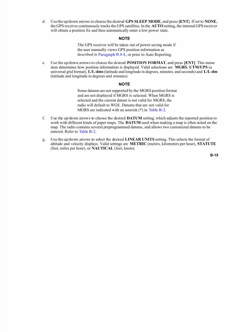
7/21/2019 RF-5800M HH Ops Manual
http://slidepdf.com/reader/full/rf-5800m-hh-ops-manual 149/199
B-15
d. Use the up/down arrows to choose the desired GPS SLEEP MODE, and press [ENT]. If set to NONE,the GPS receiver continuously tracks the GPS satellites. In the AUTO setting, the internal GPS receiverwill obtain a position fix and then automatically enter a low power state.
NOTE
The GPS receiver will be taken out of power saving mode if
the user manually views GPS position information as
described in Paragraph B.4.4., or prior to Auto Reporting.
e. Use the up/down arrows to choose the desired POSITION FORMAT, and press [ENT]. This menuitem determines how position information is displayed. Valid selections are MGRS, UTM/UPS (auniversal grid format), L/L-dms (latitude and longitude in degrees, minutes, and seconds) and L/L-dm(latitude and longitude in degrees and minutes).
NOTE
Some datums are not supported by the MGRS position format
and are not displayed if MGRS is selected. When MGRS is
selected and the current datum is not valid for MGRS, the
radio will default to WGE. Datums that are not valid for
MGRS are indicated with an asterisk (*) in Table B-2.
f. Use the up/down arrows to choose the desired DATUM setting, which adjusts the reported position towork with different kinds of paper maps. The DATUM used when making a map is often noted on themap. The radio contains several preprogrammed datums, and allows two customized datums to beentered. Refer to Table B-2.
g. Use the up/down arrows to select the desired LINEAR UNITS setting. This selects the format ofaltitude and velocity displays. Valid settings are METRIC (meters, kilometers per hour), STATUTE (feet, miles per hour), or NAUTICAL (feet, knots).

7/21/2019 RF-5800M HH Ops Manual
http://slidepdf.com/reader/full/rf-5800m-hh-ops-manual 150/199
B-16
h. Use the up/down arrows to set the ELEVATION FORMAT. This controls whether altitude is DATUMBASED or based upon MEAN SEA LEVEL.
i. Use the up/downs arrows to choose the ANGLE FORMAT, which controls the heading display.Available selections are DEG/MAGNETIC (degrees referenced to magnetic north), MIL/TRUENORTH (gunner's mils referenced to true north), MIL/MAGNETIC (gunner's mils referenced tomagnetic north) or DEG/TRUE NORTH (degrees referenced to true north).
j. Use the up/down arrows to select the desired AUTO REPORT setting. The RF-5800M-HH has thecapability to automatically report its GPS position. For Auto Report to function, the D/V TYPESELECT for the current Net has to be DIRECTED or WIRELESS IP. Valid options are: NEVER(AUTO REPORT is disabled), and TIMED. IfTIMED is selected, the user then must enter a REPORTINTERVAL in seconds (5 to 9999). The radio will then broadcast GPS information periodicallyaccording to the selected report interval value.
k. Use the up/down arrows to select the POSITION SERVER . The RF-5800M-HH can report all storedGPS information to a remote GPS position application. Valid settings are AUTO and CUSTOM IP. TheAUTO setting causes the POSITION SERVER to automatically be set to the Point-to-Point Protocol(PPP) peer IP address. The CUSTOM IP setting requires the full Position Server IP address. If anon-zero Custom IP is entered, the radio will forward GPS information to the selected Position Serverevery time it receives new GPS information from other radios. (To disable this function, enter
000.000.000.000 for the Position Server address.)l. Press the [CLR] button twice to return to the main screen. The radio is now configured for SA operation
- Internal mode.
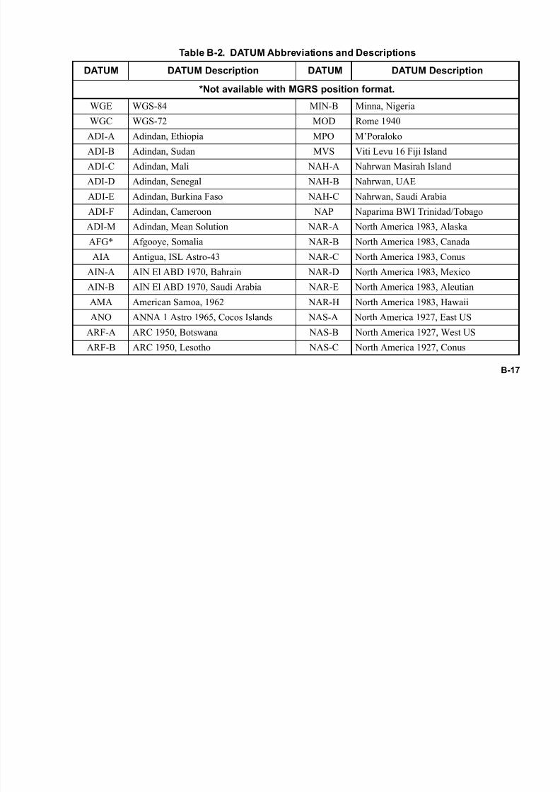
7/21/2019 RF-5800M HH Ops Manual
http://slidepdf.com/reader/full/rf-5800m-hh-ops-manual 151/199
B-17
Table B-2. DATUM Abbreviations and Descriptions
DATUM DATUM Description DATUM DATUM Description
*Not available with MGRS position format.
WGE WGS-84 MIN-B Minna, Nigeria
WGC WGS-72 MOD Rome 1940
ADI-A Adindan, Ethiopia MPO M’Poraloko
ADI-B Adindan, Sudan MVS Viti Levu 16 Fiji Island
ADI-C Adindan, Mali NAH-A Nahrwan Masirah Island
ADI-D Adindan, Senegal NAH-B Nahrwan, UAE
ADI-E Adindan, Burkina Faso NAH-C Nahrwan, Saudi Arabia
ADI-F Adindan, Cameroon NAP Naparima BWI Trinidad/Tobago
ADI-M Adindan, Mean Solution NAR-A North America 1983, Alaska
AFG* Afgooye, Somalia NAR-B North America 1983, Canada
AIA Antigua, ISL Astro-43 NAR-C North America 1983, Conus
AIN-A AIN El ABD 1970, Bahrain NAR-D North America 1983, Mexico
AIN-B AIN El ABD 1970, Saudi Arabia NAR-E North America 1983, Aleutian
AMA American Samoa, 1962 NAR-H North America 1983, Hawaii
ANO ANNA 1 Astro 1965, Cocos Islands NAS-A North America 1927, East US
ARF-A ARC 1950, Botswana NAS-B North America 1927, West US
ARF-B ARC 1950, Lesotho NAS-C North America 1927, Conus
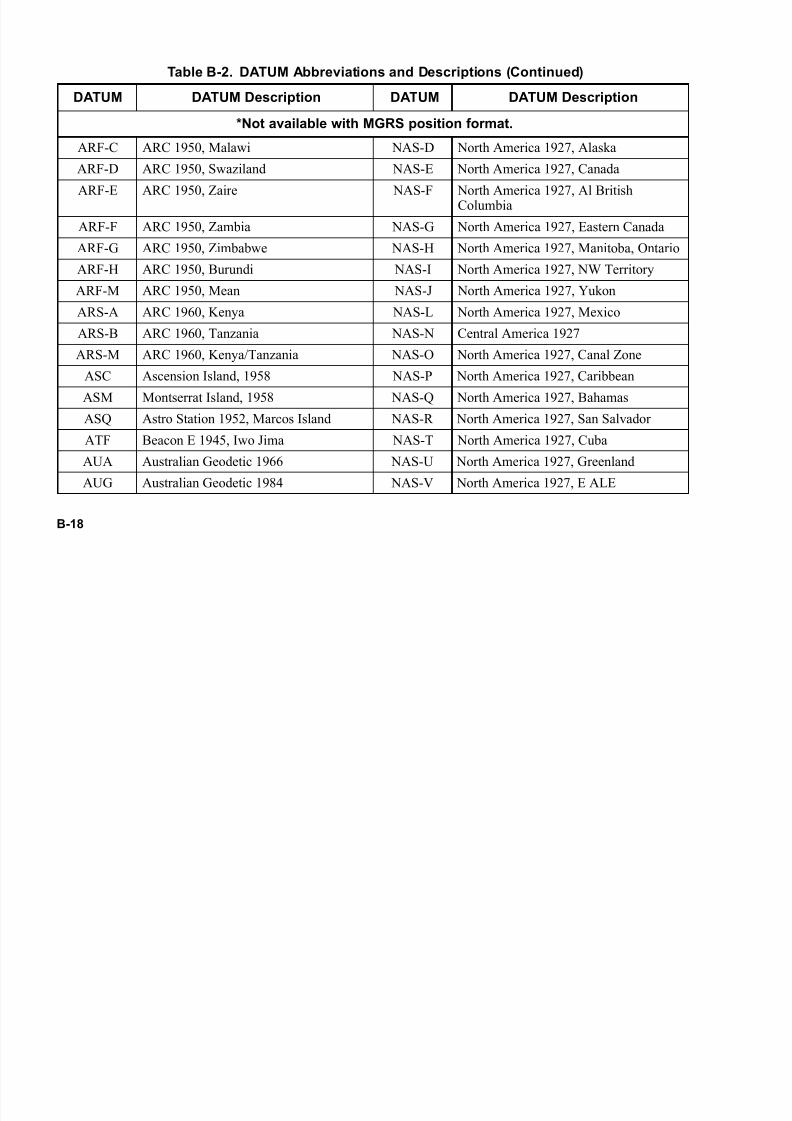
7/21/2019 RF-5800M HH Ops Manual
http://slidepdf.com/reader/full/rf-5800m-hh-ops-manual 152/199
B-18
ARF-C ARC 1950, Malawi NAS-D North America 1927, Alaska
ARF-D ARC 1950, Swaziland NAS-E North America 1927, Canada
ARF-E ARC 1950, Zaire NAS-F North America 1927, Al BritishColumbia
ARF-F ARC 1950, Zambia NAS-G North America 1927, Eastern Canada
ARF-G ARC 1950, Zimbabwe NAS-H North America 1927, Manitoba, Ontario
ARF-H ARC 1950, Burundi NAS-I North America 1927, NW Territory
ARF-M ARC 1950, Mean NAS-J North America 1927, Yukon
ARS-A ARC 1960, Kenya NAS-L North America 1927, Mexico
ARS-B ARC 1960, Tanzania NAS-N Central America 1927
ARS-M ARC 1960, Kenya/Tanzania NAS-O North America 1927, Canal Zone
ASC Ascension Island, 1958 NAS-P North America 1927, Caribbean
ASM Montserrat Island, 1958 NAS-Q North America 1927, Bahamas
ASQ Astro Station 1952, Marcos Island NAS-R North America 1927, San Salvador
ATF Beacon E 1945, Iwo Jima NAS-T North America 1927, Cuba
AUA Australian Geodetic 1966 NAS-U North America 1927, Greenland
AUG Australian Geodetic 1984 NAS-V North America 1927, E ALE
Table B-2. DATUM Abbreviations and Descriptions (Continued)
DATUM DATUM Description DATUM DATUM Description
*Not available with MGRS position format.

7/21/2019 RF-5800M HH Ops Manual
http://slidepdf.com/reader/full/rf-5800m-hh-ops-manual 153/199
B-19
BAT Djakarta, Batavia NAS-W North America 1927, W. Ale
BBOHM* Bessel-Bohm, Sweden NSD North Sahara 1959 Algeria
BER Bermuda 1957 OEG* Old Egyptian 1907BID Bissau Guinea, Bissau OGB-A* Ordinance Survey Great Britain 1936,
England
BOO Bogata Observatory OGB-B* Ordinance Survey Great Britain 1936,England, Wales
BUR Bukit Rimpah, Bangka OGB-C* Ordinance Survey Great Britain 1936,Scotland
CAC Cape Canaveral OGB-D* Ordinance Survey Great Britain 1936,Wales
CAI Campo Inchauspe 1969 OGB-M* Ordnance Survey Great Britain 1936Mean
CAO Canton Astro 1966, PH OHA-A Old Hawaiian, Hawaii
CAP Cape, South Africa OHA-B Old Hawaiian, Kauai
CAZ Camp Area Astro, Anta OHA-C Old Hawaiian, Maui
CCD S-JTSK, Czechoslovakia OHA-D Old Hawaiian, Oahu
CGE Carthage, Tunisia OHA-M Old Hawaiian, CC Mean
CHI Chatham Island 1971 OHI-A Old Hawaiian, Hawaii
Table B-2. DATUM Abbreviations and Descriptions (Continued)
DATUM DATUM Description DATUM DATUM Description
*Not available with MGRS position format.

7/21/2019 RF-5800M HH Ops Manual
http://slidepdf.com/reader/full/rf-5800m-hh-ops-manual 154/199
B-20
CHU Chua Astro, Paraguay OHI-B Old Hawaiian, Kauai
COA Corrego Alegre, Brazil OHI-C Old Hawaiian, Maui
DAL Dabola, Guinea OHI-D Old Hawaiian, OahuDID Deception Island, Antarctica OHI-M Old Hawaiian, Mean So
DOB GUX 1 Astro Guadacanal PHA Ayabelle Lighthouse
EAS Easter Island, 1967 PIT Pitcairn Astro 1967
ENW* Wake Eniwetok, 1960 PLN Pico De Las Nieves
EST COORD Sys 1937, Estonia POS Porto Santo 1936
EUR-A Europe 1950, West PRP-A PSA 1956 Bolivia
EUR-B Europe 1950, Greece PRP-B Prov South America 1956, N. Chile
EUR-C Europe 1950, Norway & Finland PRP-C Prov South America 1956, S. Chile
EUR-D Europe 1950, Portugal & Spain PRP-D Prov South America ColombiaEUR-E Europe 1950, Cyprus PRP-E Prov South America 1956, Equa
EUR-F Europe 1950, Egypt PRP-F Prov South America 1956, Guyana
EUR-G Europe 1950, England, Channel Islands PRP-G Prov South America 1956, Peru
EUR-H Europe 1950, Iran PRP-H Prov South America 1956, Venezuela
EUR-I Europe 1950, Sardinia PRP-M Prov South America 1956, Mean
Table B-2. DATUM Abbreviations and Descriptions (Continued)
DATUM DATUM Description DATUM DATUM Description
*Not available with MGRS position format.

7/21/2019 RF-5800M HH Ops Manual
http://slidepdf.com/reader/full/rf-5800m-hh-ops-manual 155/199
B-21
EUR-J Europe 1950, Sicily PTB Point 58 Mean Solution
EUR-K Europe 1950, England, Ireland PTN Pointe Noire 1948
EUR-L Europe 1950, Malta PUK* Pulkovo 1942, RussiaEUR-M Europe 1950, Mean Solution PUR Puerto Rico
EUR-S Europe 1950, Iraq, IS QAT Qatar National
EUR-T Europe 1950, Tunisia QUO Qornoq, South Greenland
EUS Europe 1979 REU Reunion Mascarene Island
FAH Oman SAE Santo 1965, Espirito
FLO Observ Meteorlog, 1939 SAN-A South American 1969, Argentina
FOT Fort Thomas 1955 SAN-B South American 1969, Bolivia
GAA Gan 1970, Maldives SAN-C South American 1969, Brazil
GEO Geodetic Datum 1949, NZ SAN-D South American 1969, ChileGIZ DOS 1968, Gizo Island SAN-E South American 1969, Columbia
GRA Graciosa Base 1948 SAN-F South American 1969, Equador
GSE Gunung Segara Kalima SAN-G South American 1969, Guyana
GUA Guam 1963 SAN-H South American 1969, Paraguay
HEN Herat North, Afganistan SAN-I South American 1969, Peru
Table B-2. DATUM Abbreviations and Descriptions (Continued)
DATUM DATUM Description DATUM DATUM Description
*Not available with MGRS position format.

7/21/2019 RF-5800M HH Ops Manual
http://slidepdf.com/reader/full/rf-5800m-hh-ops-manual 156/199
B-22
HER Hermannskogel, Old Y SAN-J South American 1969, Baltra Galap
HIT Prov. S. Chilean 1963 SAN-K South American 1969, Trinidad&Tabago
HJO Hjorsey 55, Iceland SAN-L South American 1969, VenezuelaHKD Hong Kong 1963 SAN-M South American 1969, Mean
HTN HU-TZU-SHAN, Taiwan SAO SAO Brazil Santa Maria
IBE Bellevue Efate N ERR SAP Sapper Hill 1943, Falklands
IDN* Indonesian 1974 SCK* Schwarzeck, Nambia
IND-B Indian Bangladesh SGM Selvagem Grande 1938
IND-I* Indian, India/Nepal SHB Astro DOS 71/4
IND-P* Indian, Pakistan SIR South American Geocent Ref
IND-S* Indian India SOA* South Asia, Singapore
INF-A Indian 1954, Thailand SPK-A* S-42 HungaryING-A Indian 1960, Vietnam SPK-B* S-42 Poland
ING-B Indian 1960, Vietnam SPK-C* S-42 Former Czechoslovakia
INH-A Indian 1975, Thailand SPK-D* S-42 Latvia
INH-A1 Indian 1975, Thailand SPK-E* S-42 Kazakhstan
IRL* Ireland 1965 SPK-F* S-42 Albania
Table B-2. DATUM Abbreviations and Descriptions (Continued)
DATUM DATUM Description DATUM DATUM Description
*Not available with MGRS position format.
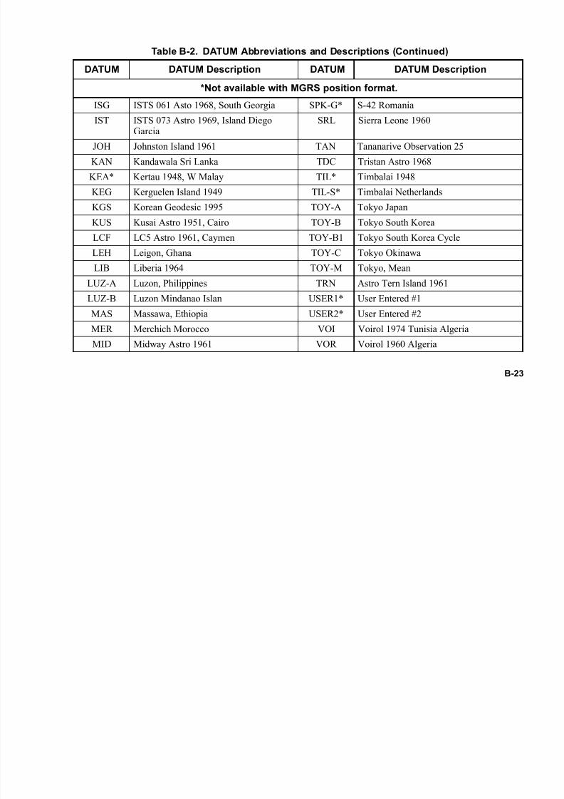
7/21/2019 RF-5800M HH Ops Manual
http://slidepdf.com/reader/full/rf-5800m-hh-ops-manual 157/199
B-23
ISG ISTS 061 Asto 1968, South Georgia SPK-G* S-42 Romania
IST ISTS 073 Astro 1969, Island DiegoGarcia
SRL Sierra Leone 1960
JOH Johnston Island 1961 TAN Tananarive Observation 25
KAN Kandawala Sri Lanka TDC Tristan Astro 1968
KEA* Kertau 1948, W Malay TIL* Timbalai 1948
KEG Kerguelen Island 1949 TIL-S* Timbalai Netherlands
KGS Korean Geodesic 1995 TOY-A Tokyo Japan
KUS Kusai Astro 1951, Cairo TOY-B Tokyo South Korea
LCF LC5 Astro 1961, Caymen TOY-B1 Tokyo South Korea Cycle
LEH Leigon, Ghana TOY-C Tokyo Okinawa
LIB Liberia 1964 TOY-M Tokyo, Mean
LUZ-A Luzon, Philippines TRN Astro Tern Island 1961
LUZ-B Luzon Mindanao Islan USER1* User Entered #1
MAS Massawa, Ethiopia USER2* User Entered #2
MER Merchich Morocco VOI Voirol 1974 Tunisia Algeria
MID Midway Astro 1961 VOR Voirol 1960 Algeria
Table B-2. DATUM Abbreviations and Descriptions (Continued)
DATUM DATUM Description DATUM DATUM Description
*Not available with MGRS position format.

7/21/2019 RF-5800M HH Ops Manual
http://slidepdf.com/reader/full/rf-5800m-hh-ops-manual 158/199
B-24
B.4.3.2 SA Configuration - External GPS
To reach the programming menus for configuring SA, perform the following steps:
a. Press the [PGM] button, use the left/right arrows to select CFIG, and press [ENT].
b. Use the left/right arrows to select GPS and press [ENT].
c. Use the up/down arrows to select EXTERNAL and press [ENT]. The message *Port Remote Baud:4800* will display for a few seconds.
d. Use the up/down arrows to choose the desired POSITION FORMAT, and press [ENT].
e. Use the up/down arrows to choose the desired DATUM, and press [ENT].
f. Use the up/down arrows to choose the desired LINEAR UNITS, and press [ENT].
g. Use the up/down arrows to choose the desired ELEVATION FORMAT, and press [ENT].
h. Use the up/down arrows to choose the desired ANGLE FORMAT, and press [ENT].
MID-1* Midway Astro 1961-1 WAK Wake Island Astro 1952
MIK Mahe 1971, Mahe Island YAC Yacare Uruguay
MIN-A Minna Cameroon ZAN Zanderij, Suriname
Table B-2. DATUM Abbreviations and Descriptions (Continued)
DATUM DATUM Description DATUM DATUM Description
*Not available with MGRS position format.

7/21/2019 RF-5800M HH Ops Manual
http://slidepdf.com/reader/full/rf-5800m-hh-ops-manual 159/199
B-25
i. Use the up/down arrows to choose whether AUTO REPORT is NEVER orTIMED, and press [ENT].If TIMED is selected, enter the reporting interval in seconds (5 to 9999), and press [ENT]. This willrepeatedly transmit GPS information at each scheduled time interval.
j. Use the up/down arrows to select the POSITION SERVER . The RF-5800M-HH can report all storedGPS information to a remote GPS position application. Valid settings are AUTO and CUSTOM IP. TheAUTO setting causes the POSITION SERVER to automatically be set to the PPP peer IP address. TheCUSTOM IP setting requires the full Position Server IP address. If a non-zero Custom IP is entered,
the radio will forward GPS information to the selected Position Server every time it receives new GPSinformation from other radios. (To disable this function, enter 000.000.000.000 for the Position Serveraddress.)
k. Press the [CLR] button twice to return to the main screen. The radio is configured for GPS/SAoperation.
B.4.3.3 Using the External GPS Receiver
To initiate Situational Awareness reporting using external GPS, the user must configure and connect the Garmin
GPS receiver to the RF-5800M-HH radio side connector.
NOTE
This procedure only details the settings required to achievecompatibility with the RF-5800M-HH radio. Refer to theGarmin manual for operating details not covered here.
Perform the following procedure to configure the Garmin Etrex Vista® for use with the RF-5800M-HH:
a. Turn the GPS receiver on by pressing the On/Off button down for at least two seconds. The main menuwill appear.

7/21/2019 RF-5800M HH Ops Manual
http://slidepdf.com/reader/full/rf-5800m-hh-ops-manual 160/199
B-26
b. From the Garmin main menu, select Setup>Interface>NMEA IN/NMEA OUT. The baud rate willautomatically default to 4800 bps. Click X to return to the Setup menu.
c. From the Garmin Setup menu, select Units>Map Datum >WGS84. Click X to return to the Setup menu.
d. From the Garmin Setup menu, select System>GPS>Normal to enable GPS tracking. Click X twice toreturn to the main menu.
e. The Etrex Vista® GPS receiver is configured for proper operation.
NOTE
Other GPS receivers can be used, but may require different
cables and configuration.
B.4.3.3.1 GPS External Mode - Connecting the Units
Perform the following procedure to begin operation:
a. Align the pin on cable connector with the hole above the radio’s side connector contacts. Use (12011-
0280-A006) cable for the Garmin Etrex Vista®, or (12011-0875) cable for Garmin GPS 76. Hold the
connector firmly in place while tightening the thumb screw. Do not overtighten.
b. Attach the cable to the GPS receiver by first opening the rubber cover on the back of the unit, and thenslide the cable connector down onto the GPS receptacle. Make sure the groove on the cable connectoris aligned properly with the receptacle.
c. Turn power on to the radio and the GPS receiver.
d. Ensure that the GPS receiver has line-of-sight visibility to the sky, and allow several minutes for satelliteacquisition.There should be at least three satellites available to obtain positioning information.
7/21/2019 RF-5800M HH Ops Manual
http://slidepdf.com/reader/full/rf-5800m-hh-ops-manual 161/199
B-27
e. If the radio has been configured to Auto Report, it will begin sending SA information at the programmedintervals. If Auto Report is not enabled, the user must perform a Forced Report to send informationmanually (refer to Paragraph B.4.4.1).
B.4.4 Viewing SA Information
To view SA position, heading, velocity, altitude, and distance data:
a. Press the [OPT] button.
b. Use the left/right arrows to select GPS, and press [ENT].
c. Select VIEW, and press [ENT]. The current position is shown on the display.
d. Press the circle arrow button to view the current heading/velocity.
e. Press the circle arrow button again to view altitude.
f. Press the circle arrow button again to return to the position screen.
g. Press [CLR] three times to return to the main screen.
NOTE
Distance is relative to the sending radio, therefore, it can only be viewed in other stations’ saved data.
To view SA data received from remote radios in the net:
a. Press the [OPT] button.
b. Use the left/right arrows to select GPS, and then press [ENT].

7/21/2019 RF-5800M HH Ops Manual
http://slidepdf.com/reader/full/rf-5800m-hh-ops-manual 162/199
B-28
c. Select VIEW, and then press [ENT]. The current GPS position is shown on the display.
d. Use the up/down arrows to scroll through saved GPS/SA data for any other stations (up to 50). Selectthe desired station to view the last saved position.
NOTE
Stored positions are not saved when the radio is turned off.
e. Press the circle arrow button to view the last saved heading, velocity, and press the circle arrow buttonfor altitude information.
B.4.4.1 Forced Reporting of GPS/SA Information
In Cipher Text (CT) mode, the GPS position can be reported at any time if the net supports the Directed Calling
feature. To transmit the current GPS information to other radios:
a. Press the [OPT] button.
b. Use the left/right arrows to select GPS, and press [ENT].
c. Select REPORT, and then press [ENT]. GPS position is transmitted.
NOTEThe current net must be configured for Directed Calling or
Wireless IP. Refer to Paragraph B.3.3 for Directed Calls, or
Paragraph B.5 for Wireless IP.
7/21/2019 RF-5800M HH Ops Manual
http://slidepdf.com/reader/full/rf-5800m-hh-ops-manual 163/199
B-29
B.5 WIRELESS IP NETWORK
The following contains information and programming instructions for Wireless IP Network.
B.5.1 Theory of Operation
The operation detailed here uses the fixed frequency and frequency hopping in the radio for IP data delivery.
Directed calling functionality is automatically integrated when the radios are configured for wireless IP operation.
These features employ a single channel, where a channel is defined as an individual frequency or as set of hopfrequencies. The radio operator is responsible for choice of channel (frequency) management - automated channel
selection is not performed by the radio.
The RF-5800M-HH radio offers a wireless IP capability that allows system operators to use IP-based PC software
applications. This feature permits the radio to interface with devices such as laptops using the radio’s PPP interface.
In addition, the radio offers an easy way to configure a wireless network without the need of adding and maintaining
routes on PCs and radios. This easy way to configure a wireless network is known as bridging. Bridging is defined
as setting the PPP PEER address on the radio equal to the radio’s active wireless IP address. This is automatically
set by the radio. With this set, the radios are behaving like a bridge rather than a router. A bridging device is able to
provide IP packet connectivity between different media within the same IP subnet space. See Figure B-2 for a basic
network configuration for wireless IP data operation.
Since all of the PCs are on the 192.168.100.X radio net, the radios automatically bridge received packets over to the
connected computer. Any application that uses the IP protocol can be used, however, the limited bandwidth of
narrowband radio communications will make the use of some applications impractical.

7/21/2019 RF-5800M HH Ops Manual
http://slidepdf.com/reader/full/rf-5800m-hh-ops-manual 164/199
B-30
B.5.2 Network Programming
The VHF-UHF Radio Programming Application (RPA) is a PC-based program used to configure Harris radios. For
Network applications, the RPA is generally used to program the Network settings in the RF-5800M-HH, although
this feature can also be programmed manually. See the Network Menu area of Figure B-1 for additional
information. General radio programming is outlined in Chapter 4.
Figure B-2. Basic Wireless IP Network
RADIO 1
PPP: 10.0.0.1
WIP: 192.168.100.1
PC 1
PPP: 192.168.100.1
KEY:WIP = Wireless IP Address
PPP = Point to Point Protocol Address
RF NET
IP: 192.168.100.X
MASK 255.255.255.0
V-0234-4200-0019
RADIO 2
PPP: 10.0.0.1
WIP: 192.168.100.2
PC 2
PPP: 192.168.100.2
RADIO 3
PPP: 10.0.0.1
WIP: 192.168.100.3
PC 3
PPP: 192.168.100.3
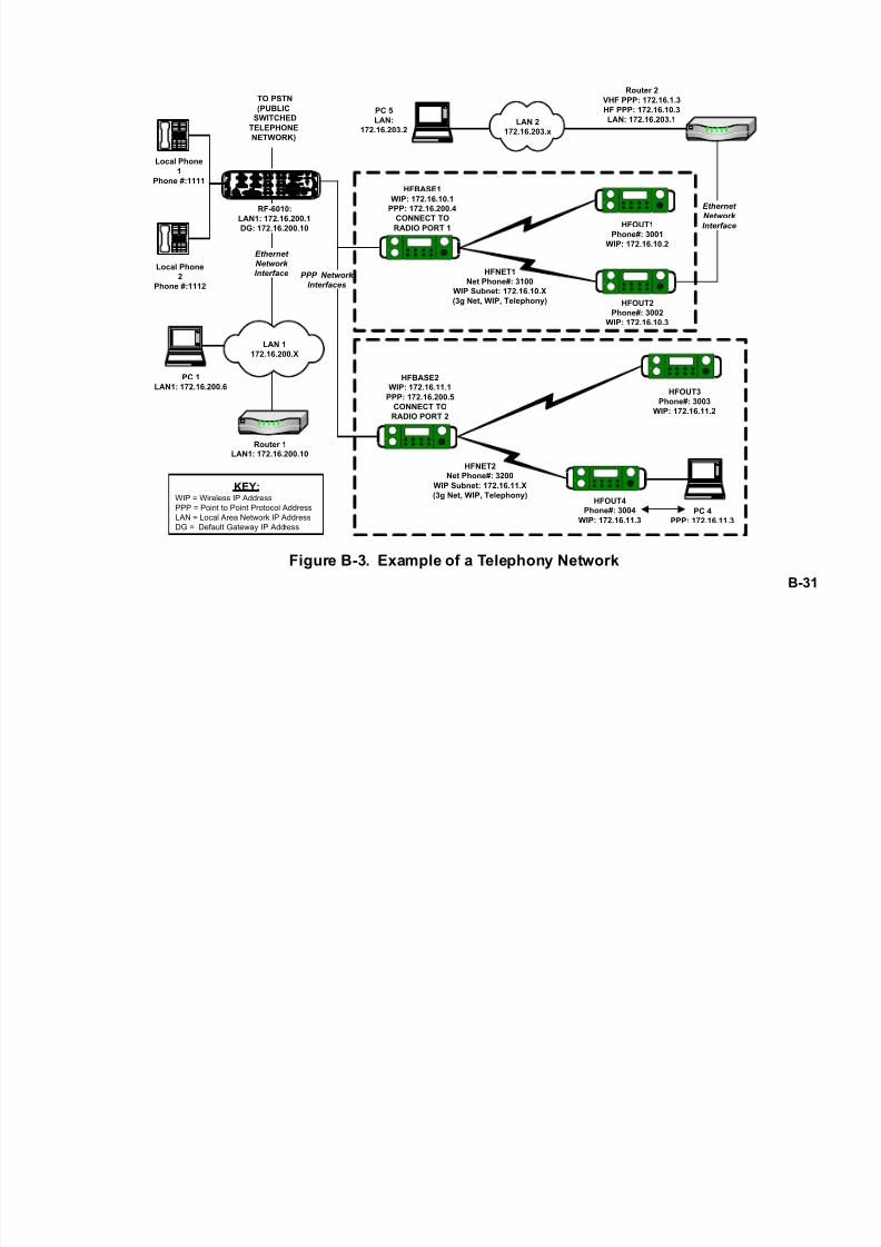
7/21/2019 RF-5800M HH Ops Manual
http://slidepdf.com/reader/full/rf-5800m-hh-ops-manual 165/199
B-31
Figure B-3. Example of a Telephony Network
Local Phone
1
Phone #:1111
RF-6010:LAN1: 172.16.200.1
DG: 172.16.200.10
PC 1
LAN1: 172.16.200.6
HFBASE1
WIP: 172.16.10.1
PPP: 172.16.200.4
CONNECT TO
RADIO PORT 1
HFBASE2
WIP: 172.16.11.1
PPP: 172.16.200.5
CONNECT TO
RADIO PORT 2
HFOUT1
Phone#: 3001
WIP: 172.16.10.2
HFOUT2
Phone#: 3002
WIP: 172.16.10.3
HFOUT3
Phone#: 3003
WIP: 172.16.11.2
HFOUT4
Phone#: 3004
WIP: 172.16.11.3
PC 5
LAN:
172.16.203.2
Router 2
VHF PPP: 172.16.1.3
HF PPP: 172.16.10.3
LAN: 172.16.203.1
PC 4
PPP: 172.16.11.3
Local Phone
2
Phone #:1112
Router 1
LAN1: 172.16.200.10
KEY:WIP = Wireless IP Address
PPP = Point to Point Protocol Address
LAN = Local Area Network IP Address
DG = Default Gateway IP Address
HFNET1
Net Phone#: 3100
WIP Subnet: 172.16.10.X
(3g Net, WIP, Telephony)
HFNET2
Net Phone#: 3200
WIP Subnet: 172.16.11.X
(3g Net, WIP, Telephony)
LAN 2
172.16.203.x
LAN 1
172.16.200.X
PPP Network
Interfaces
TO PSTN
(PUBLIC
SWITCHED
TELEPHONE
NETWORK)
Ethernet
Network
Interface
Ethernet
Network
Interface

7/21/2019 RF-5800M HH Ops Manual
http://slidepdf.com/reader/full/rf-5800m-hh-ops-manual 166/199
B-32
B.6 SHORT MESSAGING SERVICE (SMS)
SMS provides text-based messaging capability. This feature allows the user to send information using the RF-
5800M-HH front panel when voice communication is not possible or desirable (as in covert voiceless operations).
SMS can also be used to receive information when a radio is unattended. SMS operation is only available in Directed
Calling nets and Wireless IP nets.
B.6.1 SMS Operation
NOTE
SMS operation is only available in Directed Calling nets and
Wireless IP nets. Refer to Paragraph B.3.3 and
Paragraph B.5.2 to configure the radio for these net types.
Refer to Figure B-4 for the SMS menu tree.

7/21/2019 RF-5800M HH Ops Manual
http://slidepdf.com/reader/full/rf-5800m-hh-ops-manual 167/199
B-33
Figure B-4. SMS Menu Tree
F-0234-4200-0020
7 STU
OPT
SMS
SELECT NEW DELETE_ALL
DELETE ALL MESSAGES?
NO YES
REPLY
DELETE
NO YES
FORWARD
RADIO ID
ALL
DESTINATION BY
MESSAGE DESTINATION
XXX
YES
NO
SEND TO XXX
NEW MSG
CANNED MSG (NOTE 1)
LAST SENT MSG (NOTE 2)
LAST ENTERED MSG (NOTE 3)
DELETE MESSAGE?
MESSAGE TYPE
PRESS ENT TO SEND MSG
RADIO ID
ALL
DESTINATION BY
MESSAGE DESTINATION
XXX
YES
NO
SEND TO XXX
NEW MSG
CANNED MSG (NOTE 1)
LAST SENT MSG (NOTE 2)
LAST ENTERED MSG (NOTE 3)
NOTES:
1. ONLY AVAILABLE IF CANNED MESSAGES ARE SAVED IN THE MESSAGE LIST.
2. ONLY AVAILABLE IF A MESSAGE HAS BEEN SENT.
3. ONLY AVAILABLE IF A MESSAGE HAS BEEN ENTERED AND LAST ENTERED
MESSAGES ARE HELD IN MEMORY ONLY UP TO THE NEXT POWER CYCLE.
PRESS ENT TO SEND MSG
7/21/2019 RF-5800M HH Ops Manual
http://slidepdf.com/reader/full/rf-5800m-hh-ops-manual 168/199
B-34
B.6.1.1 Sending New SMS Messages
This procedure describes how to send an SMS message from the radio front panel.
a. Press the [OPT] button.
b. Use the left/right arrows to select SMS and press [ENT].
c. Use the left/right arrows to select NEW and press [ENT].
d. If no messages have ever been sent, use the up/down arrows to select either NEW or CANNED. Ifmessages have been sent, use the up/down arrows to select either NEW MSG, CANNED MSG, LASTSENT MSG, or LAST ENTERED MSG. Press [ENT].
e. The message screen will display. If this is a new message, use the keypad to enter the message text.When the message is complete, press [ENT] to continue.
f. Use the up/down arrows to select the destination where the message will be sent. Destination can bechosen either by RADIO ID number (to one specific radio) or ALL (to all radios in the net). Press[ENT].
g. If RADIO ID was selected, enter the ID number of the message destination radio to receive themessage. Press [ENT].
h. Select YES to confirm the message destination. Press [ENT].
i. The radio will display MESSAGE TRANSMITTED to confirm the message has been sent.
7/21/2019 RF-5800M HH Ops Manual
http://slidepdf.com/reader/full/rf-5800m-hh-ops-manual 169/199
B-35
B.6.1.2 Forwarding SMS Messages
This procedure describes how to forward a received SMS message to another station.
a. Press the [OPT] button.
b. Use the left/right arrows to select SMS and press [ENT].
c. Use the left/right arrows to choose SELECT, then use the up/down arrows to browse to the received
message that will be forwarded. Press [ENT].
d. The message screen will display. Use the left/right arrows to select FORWARD and press [ENT].
e. The message text may be edited or left as displayed. When the message is complete, press [ENT] tocontinue.
f. Use the up/down arrows to select the destination where the message will be sent. Destination can bechosen either by RADIO ID number (to one specific radio) or ALL (to all radios in the net). Press[ENT].
g. If RADIO ID was selected, enter the ID number of the message destination radio to receive themessage. Press [ENT].
h. Select YES to confirm the message destination. Press [ENT].
i. The radio will display MESSAGE TRANSMITTED to confirm the message has been sent.

7/21/2019 RF-5800M HH Ops Manual
http://slidepdf.com/reader/full/rf-5800m-hh-ops-manual 170/199
B-36
B.6.1.3 Viewing a Received SMS Messages
This procedure describes how to view a received SMS message. When a new message is received, it will display for
several seconds, and then a flashing M will appear to the right of the Net Number on the main screen. Once the
message has been viewed, the flashing M will disappear, but the message is held in memory until deleted by the user.
The message can be retrieved as follows:
a. Press the [OPT] button.
b. Use the left/right arrows to select SMS and press [ENT].
c. Use the up/down arrows to browse through the received messages. The radio can store up to 10messages.
B.6.1.4 Deleting SMS Messages
This procedure describes how to delete SMS messages from memory.
a. Press the [OPT] button.
b. Use the left/right arrows to select SMS and press [ENT].
c. To delete a single message:• Choose SELECT and use the up/down arrows to browse to the message to be deleted. Press
[ENT].
• Use the left/right arrows to select DELETE and press [ENT].
• Select YES to delete the message.
7/21/2019 RF-5800M HH Ops Manual
http://slidepdf.com/reader/full/rf-5800m-hh-ops-manual 171/199
B-37
d. To delete all saved messages:
• Use the left/right arrows to select DELETE_ALL and press [ENT].
• Select YES to delete all SMS messages.
B.6.2 Short Message Service Programming
This section describes programming the SMS feature from the radio front panel. Refer to Chapter 4 for general radio
programming.
a. Press the [PGM] button.
b. Use the left/right arrows to select CFIG, and press [ENT].
c. Use the left/right arrows to select SMS, and press [ENT].
d. Use the left/right arrows to select SETTINGS, and press [ENT].
e. Use the up/down arrows to select the desired TEXT ENTRY MODE. Valid entries are Insert andOverwrite. Press [ENT].
f. Use the up/down arrows to set TEXT PREDICTION. Valid entries are On or Off . If enabled, thisfeature will automatically “predict” (based upon prior text entries) the letter which displays next whenentering a message from the front panel. Press [ENT].
g. Use the up/down arrows to set TONE ALERT to On or Off . If enabled, a beep sounds when a newmessage arrives. Press [ENT].
h. Use the up/down arrows to select the desired CAP MODE. This feature causes entered characters toautomatically be set to capital letters. Valid entries are On or Off . Press [ENT].
7/21/2019 RF-5800M HH Ops Manual
http://slidepdf.com/reader/full/rf-5800m-hh-ops-manual 172/199
B-38
i. Use the up/down arrows to set ACKNOWLEDGE to On or Off . When enabled, this featureautomatically sends an acknowledgement to the sender when a message arrives. Press [ENT].
B.6.2.1 Composing SMS Canned Messages
Up to ten messages can be pre-entered and saved for future transmission using the Canned Message feature.
a. Press the [PGM] button.
b. Use the left/right arrows to select CFIG, and press [ENT].
c. Use the left/right arrows to select SMS, and press [ENT].
d. Use the left/right arrows to select CANNED, and press [ENT]. The menu of Canned Messages (1- 10)displays. Messages can be created, edited or deleted from the front panel.
e. To create a new Canned Message, use the left/right arrows to select Edit, then use the up/down arrowsto select the desired message number and press [ENT]. Canned Messages can be up to 160 charactersin length.
f. Using the front panel keypad, type the desired canned message. The keys are used to type any of thecharacters which appear on that key. For example, the 5 key is used to type either M, N, O, or 5. If youwant to type the letter O, rapidly press the 5 key three times until the letter O is displayed. After a shortdelay, the cursor advances to the next position. Special characters, including delete and space, areaccessed by pressing the circular arrow key.
g. When the canned message is composed, press [ENT] to save.

7/21/2019 RF-5800M HH Ops Manual
http://slidepdf.com/reader/full/rf-5800m-hh-ops-manual 173/199
B-39
B.7 FALCON WATCH™ SENSOR ALERTS
The Falcon Watch™ system is designed to meet a wide range of challenging surveillance and security needs. The
Falcon Watch™ system utilizes the RF-5400V-SR Sensor Relay node, multiple detector types, and advanced
software to provide true, real-time Situational Awareness. The system processes input data from seismic, magnetic,
and passive infrared detectors, and transmits alerts when valid events occur. Falcon Watch™ Sensor Alerts for the
RF-5800M-HH consist of text messages and GPS coordinate information received from an RF-5400V-SR Sensor
Relay. Refer to the Falcon Watch™ Falcon II System Manual (10515-2801-4200) for complete system operation
and programming.
There are three types of reports that can be received by the RF-5800M-HH:
• Activity Report - Indicates an Alert condition was detected from a Sensor detector.
• Tamper - Indicates if one or more of the Sensor Relay tamper indicators was tripped.
• Status/Health - Indicates battery on the Sensor Relay is low.
Using low band VHF frequencies, the RF-5400V-SR broadcasts alert reports to all radios in the net. When an alert
is first received by the RF-5800M-HH radio, it can be stored and displayed. The following sensor data is included
in the report:
• Sensor Name (or ID number if no name has been assigned)
• Detector Type - Seismic, Passive Infrared (PIR), or Magnetic
• Target Type - Vehicle, Personnel, etc.
• Bearing and Distance to sensor
• GPS coordinates of sensor
7/21/2019 RF-5800M HH Ops Manual
http://slidepdf.com/reader/full/rf-5800m-hh-ops-manual 174/199
B-40
• Direction Indication (Left-to-Right, Right-to-Left)
• Date and Time of alert
NOTE
Direction information is only displayed if programmed on the
RF-5400V-SR sending the sensor event report. Direction
information for magnetic detectors is always displayed as
unknown.
To create a compatible communications net between the RF-5400V-SR and the RF-5800M-HH radio, the following
constraints must be considered while programming the radio.
• The radio net must be either Fixed Frequency/LOS or Quicklook 1A Frequency Hopping, and operated in
the frequency range 30 MHz to 108 MHz.
• Citadel encryption is required; the net cannot be operated in Plain Text (PT).
• Alert operation is only available in Directed Calling nets and Wireless IP nets.
• To ensure reliable communications, it is recommended that the RF-5800M-HH radio is programmed using
Falcon Watch™ Falcon II Mission Programming Application. This ensures that the radio is programmed
with the same RF-6550V VHF-UHF RPA plan file that is used to program the RF-5400V-SR Sensor Node.
B.7.1 Sensor Alert Operation
When a Sensor Alert message is received at the RF-5800M-HH, it is:
• Displayed on the radio screen for 30 seconds (if ALERT DISPLAY is enabled).
• Announced with an audible tone (if ALERT TONE is enabled).
• Stored in the radio’s internal message log.

7/21/2019 RF-5800M HH Ops Manual
http://slidepdf.com/reader/full/rf-5800m-hh-ops-manual 175/199
B-41
When a new message is received, it will display for 30 seconds, and then a flashing A will appear to the right of the
Net Number on the main screen. The flashing A may be removed by viewing the list of stored messages under OPT>
ALERTS, but the message is held in memory until deleted by the user.
NOTE
To avoid SMS message screen display time-outs after 30
seconds the user can scroll between menu options or switch to
another screen to retain the message display.
If a Sensor Alert message is being displayed when another Sensor Alert message is received, the second Sensor Alert
is queued and displayed after the first Sensor Alert message is removed from the display. An alert display will
timeout after 30 seconds, or the operator may press CLR to remove it from the display.
If an SMS message arrives while a Falcon Watch™ Sensor Alert message is being displayed, the SMS message (and
any subsequent SMS messages) will take precedence over the Falcon Watch™ Sensor Alert message. The
interrupted Falcon Watch™ message is displayed after all SMS messages have been removed from the display
screen.
The Falcon Watch™ Sensor Alert popup message consists of two screens that display the information received from
the RF5400V-SR Sensor Node. See Figure B-5. Use the up and down arrow keys to shift between the two displays.
The popup displays will remain for 30 seconds unless CLR is pressed by the user. Once removed, the alert messageis still stored in memory and can be returned to the display by using the OPT menu.
The list of possible alert messages are shown in Table B-3. The alert message is determined by how the RF-5400V-
SR sensor node is programmed when using the Falcon Watch™ Falcon II Mission Programming Application.
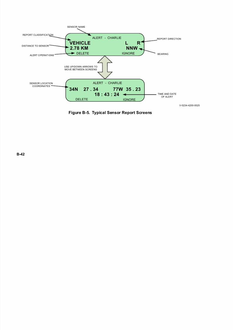
7/21/2019 RF-5800M HH Ops Manual
http://slidepdf.com/reader/full/rf-5800m-hh-ops-manual 176/199
B-42
Figure B-5. Typical Sensor Report Screens
ALERT - CHARLIE
VEHICLE2.78 KM NNW
L R
DELETE IGNORE
SENSOR NAME
REPORT CLASSIFICATION
DISTANCE TO SENSOR
REPORT DIRECTION
BEARING
34N 27 . 34 77W 35 . 2318 : 43 : 24
ALERT - CHARLIE
DELETE IGNORE
SENSOR LOCATION
COORDINATES
TIME AND DATE
OF ALERT
USE UP/DOWN ARROWS TO
MOVE BETWEEN SCREENS
ALERT OPERATIONS
V-0234-4200-0025

7/21/2019 RF-5800M HH Ops Manual
http://slidepdf.com/reader/full/rf-5800m-hh-ops-manual 177/199
B-43
Table B-3. Alert Messages
Message
Unknown
Personnel
Vehicle
Light VehicleHeavy Vehicle
Wheeled Vehicle
Tracked Vehicle
Airborne
Helicopter
Propeller Aircraft
Jet Aircraft
Animal

7/21/2019 RF-5800M HH Ops Manual
http://slidepdf.com/reader/full/rf-5800m-hh-ops-manual 178/199
B-44
B.7.1.1 Filtering Alert Messages
A sensor could transmit multiple false reports under some circumstances such as incorrect sensitivity settings,
unusual weather conditions, etc. This will fill memory quickly with unnecessary information. The sensor can be
temporarily ignored, which removes the message from the display and deletes it from the stored message list. All
further messages from the filtered sensor will be ignored (neither displayed nor stored). However, all previously
stored messages from this sensor that are currently in the radio's list will remain.
To filter a sensor:
a. With the sensor alert message on the display, use the left/right arrows to select IGNORE and press[ENT].
b. Select YES to ignore all further reports received from the sensor.
c. Refer to Paragraph B.7.2.2 for sensor display status.
B.7.1.2 Deleting Alert Messages
The Sensor Alert popup messages can be deleted by the operator, in which case, the message is removed from the
display and deleted from the stored message list.
To delete a single message:
a. Use the left/right arrows to select DELETE and press [ENT].
b. Select YES to delete the message.

7/21/2019 RF-5800M HH Ops Manual
http://slidepdf.com/reader/full/rf-5800m-hh-ops-manual 179/199
B-45
B.7.2 Stored Alert Messages
Upon reception, the Sensor Alert message is saved in a list of stored messages. The ten most recent alert messages
are stored in non-volatile memory in the radio, and are saved even if the radio is turned off. Up to 30 alert messages
can be stored for viewing, but those older than the last ten are lost when the radio is turned off.
B.7.2.1 Reviewing Alert Messages
The list of messages currently stored in the radio can be viewed by the operator. To select a Sensor Alert messagefrom the list of stored messages and display the message, perform the following procedure:
a. Press the [OPT] button.
b. Use the left/right arrows to select ALERTS and press [ENT].
c. Use the up/down arrows to scroll to the desired alert message. Use the left/right arrows to chooseSELECT. Press [ENT].
d. The message screen will be displayed.
B.7.2.2 Display All Alert Messages
If messages from a sensor (all sensors in the current net) have been set at the radio as Ignored, they can be returnedto normal display operation using the following procedure:
a. Press the [OPT] button.
b. Use the left/right arrows to select ALERTS and press [ENT].
c. Use the left/right arrows to choose DISPLAY_ALL. Press [ENT].
d. Use the up/down arrows to select YES to unfilter all messages from the sensor. Press [ENT].

7/21/2019 RF-5800M HH Ops Manual
http://slidepdf.com/reader/full/rf-5800m-hh-ops-manual 180/199
B-46
B.7.2.3 Deleting All Alert Messages
This procedure describes how to delete Alert messages from memory.
a. Press the [OPT] button.
b. Use the left/right arrows to select ALERT and press [ENT].
c. Use the left/right arrows to choose DELETE_ALL. Press [ENT].
d. Use the up/down arrows to select YES to delete all messages saved in memory. Press [ENT].
B.7.3 Sensor Alert Programming
Perform the following procedure to activate Sensor Alerts from the front panel of the RF-5800M-HH. Refer to
Chapter 4 for general radio programming.
a. Press the [PGM] button.
b. Use the left/right arrows to select CFIG, and press [ENT].
c. Use the left/right arrows to select ALERTS, and press [ENT].
d. Use the up/down arrows to set ALERTS ENABLE. Valid entries are ON or OFF. If ON, this featurewill automatically receive and log any incoming messages from the Falcon Watch™ system. Press[ENT].
e. Use the up/down arrows to set ALERT DISPLAY. Valid entries are ON or OFF. If ON, the radio willdisplay incoming alerts for 30 seconds as they are received, then they will be added to the alert log forfuture viewing. Press [ENT].

7/21/2019 RF-5800M HH Ops Manual
http://slidepdf.com/reader/full/rf-5800m-hh-ops-manual 181/199
B-47
f. Use the up/down arrows to set ALERT TONE to ON or OFF. If ON, a beep sounds when a newmessage arrives. Press [ENT] to accept the setting and return to the ALERTS menu.
g. Press [CLR] twice to close Programming mode and return to the main operating display.
B.7.4 Tamper Alert Reports
The RF-5400V-SR node may be programmed to detect tamper conditions and report them to the RF-5800M-HH.
Possible tamper alert messages that can be displayed on the radio are listed in Table B-4.
B.7.5 Low Battery Alert
The RF-5400V-SR node will send low battery alerts to the RF-5800M-HH.
Table B-4. Tamper Alerts
Message
Device Movement
Detector Chan. A
Detector Chan. B
Detector Chan. C
Remote Sensor

7/21/2019 RF-5800M HH Ops Manual
http://slidepdf.com/reader/full/rf-5800m-hh-ops-manual 182/199
B-48
This page intentionally left blank.

7/21/2019 RF-5800M HH Ops Manual
http://slidepdf.com/reader/full/rf-5800m-hh-ops-manual 183/199
G-1
GLOSSARY
-A-
AES Advanced Encryption Standard
AM Amplitude Modulation
ANC Ancillary
ASK Amplitude Shift Keying
AUX Auxiliary
-B-
BIT Built-In Test
BITE Built-In Test Equipment. Self-test software that
is built into the radio.
-C-
CAM Custom Algorithm Modification or Customer
Algorithm Modification or Citadel Algorithm
Modification
COMSEC Communications Security

7/21/2019 RF-5800M HH Ops Manual
http://slidepdf.com/reader/full/rf-5800m-hh-ops-manual 184/199
G-2
GLOSSARY - CONTINUED
-C- - Continued
Configuration The process of setting parameter values which
define the current hardware setup and/or opera-
tional modes. Also, a collection of all such values
at any given time.
CT Cipher Text
CTCSS Continuous Tone Coded Squelch System
CTI Computer Telephony Interface
Cursor A visible position indicator on the radio's
display. This shows where the next entry from the
keypad will be written to the display.
CVSD Continuously Variable Slope Delta. Used on
wideband digital voice.
7/21/2019 RF-5800M HH Ops Manual
http://slidepdf.com/reader/full/rf-5800m-hh-ops-manual 185/199
G-3
GLOSSARY - CONTINUED
-D-
Display An electronic device which produces visible
output (in non-permanent form). The output may
take the form of text, graphics, or a combination
of the two.
D/V Data/Voice
Digital Voice (DV) Analog voice that has been converted into a
digital data stream of 1s and 0s.
-E-
ECCM Electronic Counter Counter Measures
FH Frequency Hopping
7/21/2019 RF-5800M HH Ops Manual
http://slidepdf.com/reader/full/rf-5800m-hh-ops-manual 186/199
G-4
GLOSSARY - CONTINUED
-F-
Field An area on a display that contains operator
information, or provides an area for an operator
to input or select data.
FM Frequency Modulation
FP Front Panel
FSK Frequency Shift Keying
-G-
GPS Global Positioning System
-H-
Hang Time The length of time after which the radio returns to
automatic scan after signal presence is lost on a
net.
Harmonic A frequency that is a whole number multiple of
the fundamental frequency - for example, 60
MHz is a harmonic of 30 MHz.
HCAI Harris Common Air Interface specification.

7/21/2019 RF-5800M HH Ops Manual
http://slidepdf.com/reader/full/rf-5800m-hh-ops-manual 187/199
G-5
GLOSSARY - CONTINUED
-H- - Continued
Hexadecimal Base 16 numbering structure used in computer
systems. Valid characters are 0 - 9, and A - F.
HSIP Harris Session Initiation Protocol used to support
RF-6010 to radio functionality.
Hold Time The length of time that the radio, after detecting
signal presence on a net, will return to automatic
scan even if the signal is still present on that net.
-I-
ID Identification
IP Internet Protocol
-J-
-K-
-L-
Li-ION Lithium-Ion
LCD Liquid Crystal Display
LOS Line of Sight
7/21/2019 RF-5800M HH Ops Manual
http://slidepdf.com/reader/full/rf-5800m-hh-ops-manual 188/199
G-6
GLOSSARY - CONTINUED
-M-
Memory A term used to describe the storage internal to the
radio.
Menu A list of options presented to a user along with
some means of selecting one of those options.MHz Abbreviation for megahertz, or millions of cycles
per second.
MIC Microphone
MINERR Standard Citadel Mode - The default COMSEC
mode supported across all net types: Simple,
Directed Calling, and Wireless IP.
MGRS Military Grid Reference System
Mode The operational state of the radio as defined by
accessing from the [MODE] button (TEST, RE-
TRANSMIT, CLONE, and KEYPAD LOCK).Modem Acronym for MOdulator/DEModulator. This is a
type of data communications equipment which
converts digital signals into an analog format
(modulation) suitable for transmission through
various media and reconverts received signals
into a digital format (demodulation).

7/21/2019 RF-5800M HH Ops Manual
http://slidepdf.com/reader/full/rf-5800m-hh-ops-manual 189/199
G-7
GLOSSARY - CONTINUED
-N-
Net Configuration Data describing a net including name, frequency,
data/voice settings, squelch, and transmit power.
Net A group of radios that share common communi-
cations parameters, such as frequencies, etc.
Non-Volatile Information that is not lost when a unit is turned
off. Non-volatile data is often retained by means
of a battery back-up.
-O-
OVM Option Validation Matrix
-P-
PA Power Amplifier
PC Personal Computer
PIR Passive Infrared
PT Plain Text
PTT Push-to-Talk
PPP Point-to-Point Protocol

7/21/2019 RF-5800M HH Ops Manual
http://slidepdf.com/reader/full/rf-5800m-hh-ops-manual 190/199
G-8
GLOSSARY - CONTINUED
-Q-
-R-
Radio Presets A named, predefined set of radio parameters that
allows the radio to be set up using only the preset
name. Also see Net Configuration.
RAM Random Access Memory
RCV Receive
RCVR Receiver
RESYNC COMSEC mode that allows a radio on simple
voice/data nets (not directed calling or wireless
IP nets) to receive an encrypted transmission al-
ready in progress.
RF Radio Frequency
RPA Radio Programming Application
RS-232 A set of standard specifications for the design of
serial ports. An RS-232 port is a serial port which
conforms to the EIA standards.
R/T Receiver-Transmitter

7/21/2019 RF-5800M HH Ops Manual
http://slidepdf.com/reader/full/rf-5800m-hh-ops-manual 191/199
G-9
GLOSSARY - CONTINUED
-R- - Continued
RX Receive
-S-
SA Situational Awareness
SMB Sub-Miniature B - a type of antenna connector
SMS Short Message Service
SNR Signal to Noise Ratio
Squelch (SQL) The ability to mute the receive audio unless the
radio receives the appropriate signal. Can be
either digital squelch, tone squelch, or noise
squelch.
-T-
TEK Traffic Encryption Key
TNC Threaded N-Connector - a type of antenna
connector
TOD Time-Of-Day
TRANSEC Transmission Security
TX Transmit

7/21/2019 RF-5800M HH Ops Manual
http://slidepdf.com/reader/full/rf-5800m-hh-ops-manual 192/199
G-10
GLOSSARY - CONTINUED
-U-
UHF Ultra High Frequency
UTC Universal Coordinated Time - International basis
for civil and scientific timekeeping (see Zulu).
UTM Universal Transverse Mercator - This Position
Format setting determines how position
information is displayed.
UTM/UPS Universal Transverse Mercator/Universal Polar
Stereographic - This Position Format setting
determines how position information is
displayed.
-V-
VAA Vehicular Adapter Amplifier
VAU Vehicular Adapter Unit
VHF Very High Frequency
VOC Voice
Volatile Information that is lost when a unit is turned off.

7/21/2019 RF-5800M HH Ops Manual
http://slidepdf.com/reader/full/rf-5800m-hh-ops-manual 193/199
G-11
GLOSSARY - CONTINUED
-W-
WBFSK Wideband Frequency Shift Keying
-X-
XCVR Transceiver
XMT Transmit
XMTR Transmitter
-Y-
-Z-
Zeroize A command sequence which erases all pro-
grammed channel parameter and option settings.
Zulu Greenwich Mean Time - International basis for
civil and scientific timekeeping (see UTC).

7/21/2019 RF-5800M HH Ops Manual
http://slidepdf.com/reader/full/rf-5800m-hh-ops-manual 194/199
G-12
This page intentionally left blank.
7/21/2019 RF-5800M HH Ops Manual
http://slidepdf.com/reader/full/rf-5800m-hh-ops-manual 195/199
INDEX-1
A
Attaching a PC to Radio For VHF-UHF RPAProgramming ...............................................................4-2Automatic Test .............................................................3-12
B
Basic Operation From Net Preset ................................3-18Batteries .......................................................................5-6Battery Information ......................................................2-6
Battery Life ..................................................................5-6Battery Storage and Maintenance ................................5-9Battery Test ..................................................................3-14Before Operating the RF-5800M-HH ..........................3-16BIT Faults ....................................................................5-3Black Digital Retransmit Operation ............................3-38Breaking into a Directed Call ......................................B-8Busy State ....................................................................B-9BYPASS Programming ................................................4-12
C
CFIG Menu ..................................................................4-24Chassis Connector Pinout Data ....................................A-1Cipher Text Compatibility ...........................................3-18Clone Mode ..................................................................3-47compatibility ................................................................1-8Compatible Cables and ConnectorS ............................1-9Composing SMS Canned Messages ............................B-38COMSEC .....................................................................3-28CONFIG Programming ................................................4-22Configurations .............................................................1-5Controls, Indicators, and Connectors ...........................3-2Corrective Maintenance ...............................................5-2
D
Data/Voice (D/V) Settings ...........................................3-23
Description ...................................................................B-6, B-12Directed Calling ...........................................................B-6Directed Calling Programming ....................................B-9Disposing of Li-Ion Batteries ......................................5-8
E
ENCKEY Programming ..............................................4-13Equipment Description ................................................1-2Error Messages and Corrective Actions ......................B-11
F
Features ........................................................................1-4Fixed Frequency Net Programming .............................4-17Forced Reporting of GPS/SA Information ..................B-28Frequency Hopping Net Programming ........................4-19Frequency Separation ..................................................3-44
G
GENERAL Programming ............................................4-12GENERAL Settings .....................................................4-24GPS ..............................................................................3-29GPS External Mode - Connecting the Units ................B-26
H
Hardware for Retransmission/Repeater Setup .............3-44HOPSET Programming ...............................................4-14
I
Initial Tests ...................................................................3-11Initiating a Directed Call Using a Radio ID ................B-7Introduction ..................................................................3-1, B-1Items Included with the RF-5800M-HH ......................2-1
K
Keypad Lock ................................................................3-10
7/21/2019 RF-5800M HH Ops Manual
http://slidepdf.com/reader/full/rf-5800m-hh-ops-manual 196/199
INDEX-2
L
LCD Display - Preset Screens .....................................3-19Level Access ................................................................4-10Locking the Keypad .....................................................3-10Locking the Radio ........................................................3-9LOCKSET Programming ............................................4-15LOCKSETS (Hopping Only) .......................................3-30LT Button Operation ....................................................3-15
N Net Programming .........................................................4-16, B-9 Net Programming Considerations ................................4-16 Net Scanning ................................................................3-31 Network Programming ................................................B-30 Non-BIT Faults ............................................................5-3 NORM Menu ...............................................................4-12 Number Entry ..............................................................3-8
O
Operation Task Summary ............................................3-1Optional Items Available .............................................2-5Optional Manual Tests .................................................3-12Optional Version Tests .................................................3-15Overview - Contents of a Net Preset ...........................3-19
P
Password Programming ...............................................4-11PORTS Menu ...............................................................4-22POWER .......................................................................3-29Preventive Maintenance ...............................................5-1PRIORITY Programming ............................................4-21Programming Beacon Settings .....................................4-25Programming Clock Settings .......................................4-27Programming External Device (EXT_DEV) Settings .4-27Programming GPS Settings .........................................4-28
Programming Menu Tree .............................................4-3Programming Network IP Settings ..............................4-28Programming SMS Settings ........................................4-28Programming Task Summary ......................................4-1Purpose Of This Manual ..............................................1-2
R
RADIO .........................................................................3-29Radio Call Inactivity Timer .........................................B-9
Radio Lock ...................................................................3-9Radio Options ..............................................................3-27Radio Power-On ..........................................................3-9Radio Programming Versus Temporary Overrides ......3-24Receiving Wireless Cloning Information ....................3-47Recharging the Li-Ion Battery Packs ...........................5-7Red Analog Retransmit Operation ...............................3-40Remote Control ............................................................3-36REMOTE Port Programming ......................................4-23Repeater Retransmission Operation ............................3-42Retransmit Mode .........................................................3-37Retransmit Settings ......................................................3-46
S
SA Configuration - External Mode ..............................B-24SA Configuration - Internal Mode ...............................B-14SA Features ..................................................................B-13SA Operation ...............................................................B-14Safety Precautions .......................................................1-1SAVE ...........................................................................3-28Scan List Programming ...............................................4-21SCAN Menu ................................................................4-20Search and Rescue Beacon Mode ................................3-36Security Menu (SECUR) .............................................4-10Select a Net Preset .......................................................3-23Selecting PT or CT .......................................................3-18
7/21/2019 RF-5800M HH Ops Manual
http://slidepdf.com/reader/full/rf-5800m-hh-ops-manual 197/199
INDEX-3
Setup Procedure ...........................................................2-9Short messaging service (SMS) ...................................B-32Short Messaging Service Programming ......................B-34, B-35,
......................................................................B-36, B-37, ......................................................................B-46
Situational Awareness (SA) .........................................B-12SMS .............................................................................3-29, 3-30SPKR ...........................................................................3-28Squelch (SQL) Settings ...............................................3-23System Teardown Procedure ........................................2-10
T
Terminating a Directed Call .........................................B-8Theory of Operation .....................................................B-29Transmitting Wireless Cloning Information ................3-49Troubleshooting Procedures ........................................5-3
U
Unlocking the Keypad .................................................3-11Unlocking the Radio ....................................................3-10Using the External GPS Receiver ................................B-25
V
Verifying The Status Of A Wireless Cloning Transfer 3-50View Data Port Setting ................................................4-23Viewing SA Information ..............................................B-27Voice/Data and Cipher Text Compatibility ..................3-17Voice/Data Compatibility .............................................1-7
W
Wireless IP Network ....................................................B-29
Z
Zero Operation .............................................................3-25

7/21/2019 RF-5800M HH Ops Manual
http://slidepdf.com/reader/full/rf-5800m-hh-ops-manual 198/199
INDEX-4
This page intentionally left blank.

7/21/2019 RF-5800M HH Ops Manual
http://slidepdf.com/reader/full/rf-5800m-hh-ops-manual 199/199