rf & microwave research facilities - university of … · research facilities department of...
TRANSCRIPT
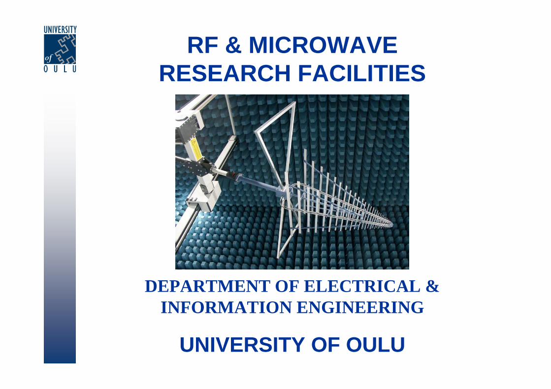
RF & MICROWAVERESEARCH FACILITIES
DEPARTMENT OF ELECTRICAL & INFORMATION ENGINEERING
UNIVERSITY OF OULU
Optoelectronics and Measurement Techniques Laboratory
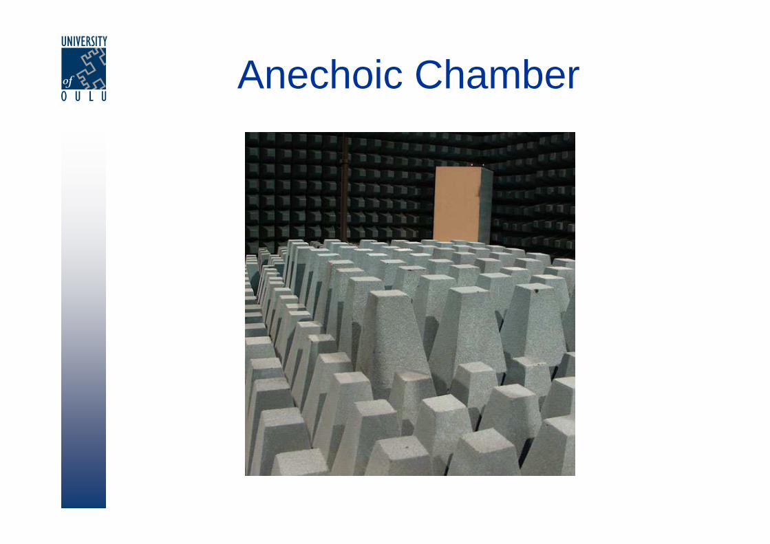
Anechoic Chamber
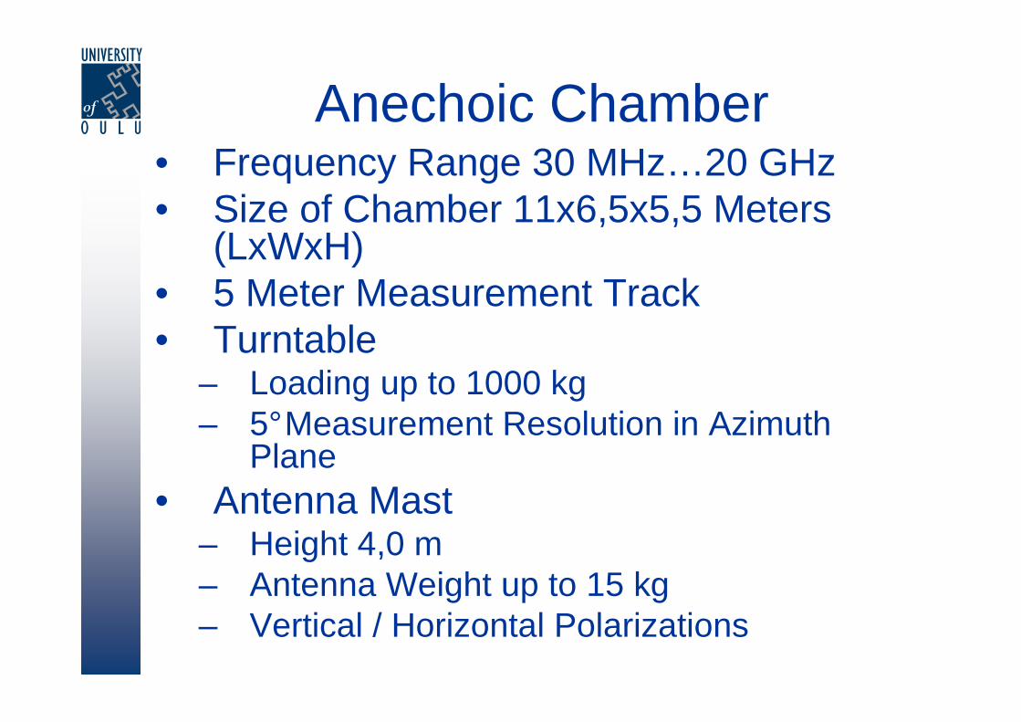
Anechoic Chamber• Frequency Range 30 MHz…20 GHz• Size of Chamber 11x6,5x5,5 Meters
(LxWxH)• 5 Meter Measurement Track• Turntable
– Loading up to 1000 kg– 5°Measurement Resolution in Azimuth
Plane• Antenna Mast
– Height 4,0 m– Antenna Weight up to 15 kg– Vertical / Horizontal Polarizations

EMC Measurements

EMC Measurements
• EMC Measurements 30 MHz…20 GHz– Power Amplifier up to 50 W at 1…1000 MHz
Frequency Range
• EMC32, Rohde&Schwarz System Software– Emission Measurements (EMI)– Electromagnetic Susceptibility Measurements
(EMS)
Telecommunication Laboratory

Satimo StarLab – MultiprobeSystem
Measurement System for Handset Antennas

Satimo StarLab• Measurement Bandwidth 0,8…6 GHz• 3D Radiation Pattern Measurement Time
~2 min• Size of Antenna between 10…40 cm• Antenna Weight up to 10 kg• Option to Measure with Phantom Head• Reference Dipole Kit (900, 1800, 1900,
2050 & 2450 MHz)
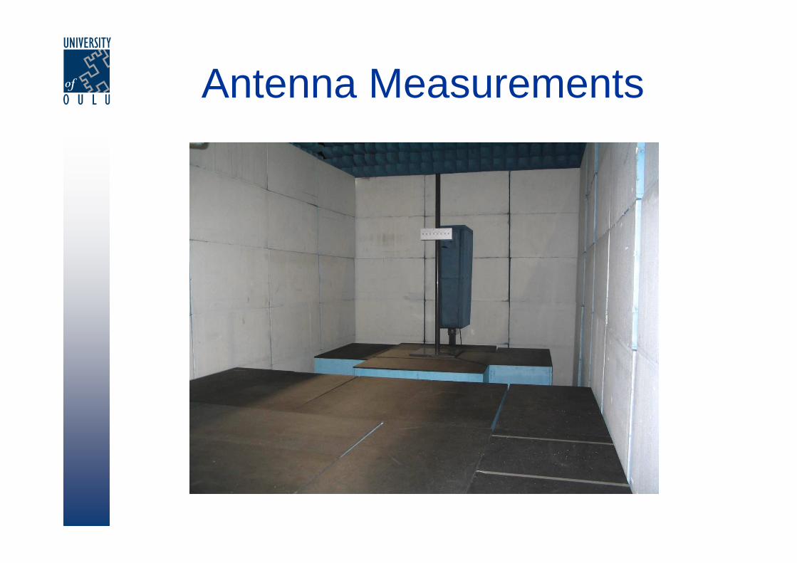
Antenna Measurements
Antenna Measurements
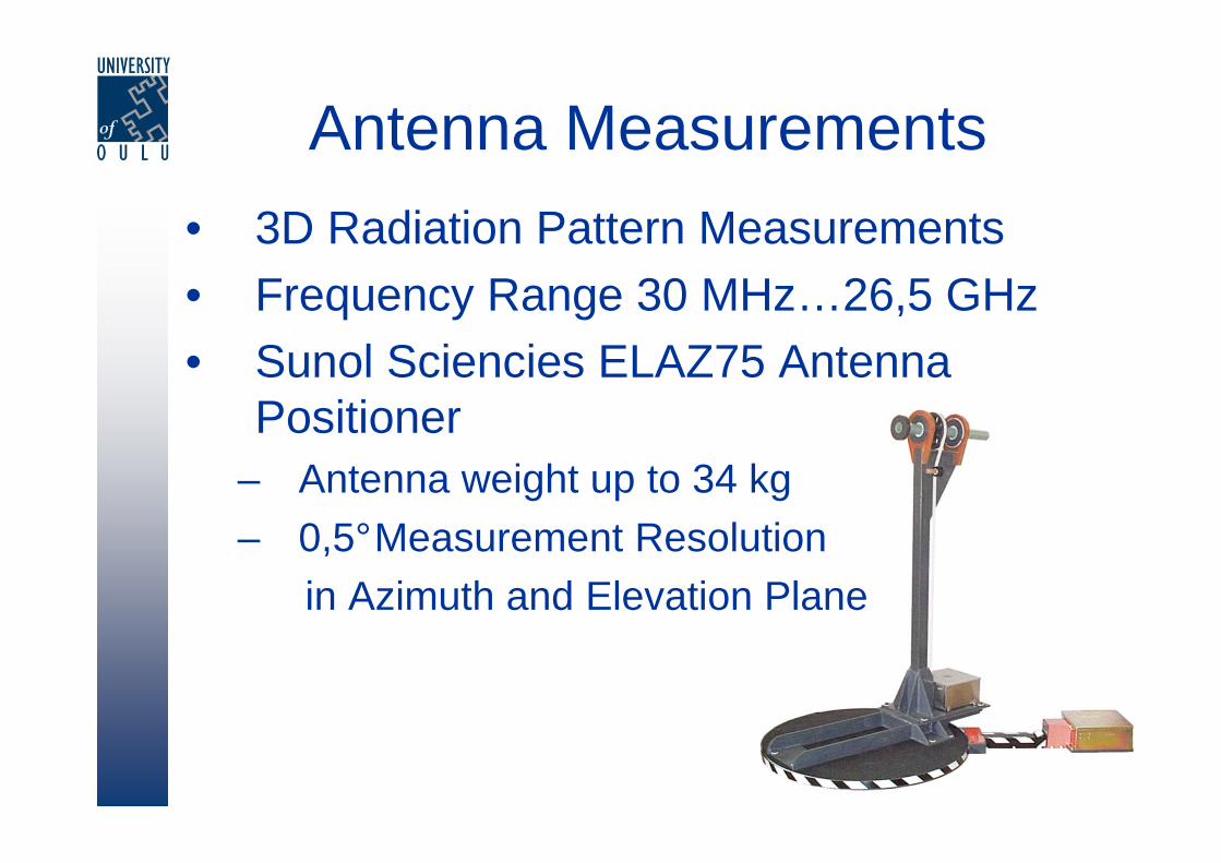
• 3D Radiation Pattern Measurements• Frequency Range 30 MHz…26,5 GHz• Sunol Sciencies ELAZ75 Antenna
Positioner– Antenna weight up to 34 kg
– 0,5°Measurement Resolutionin Azimuth and Elevation Plane
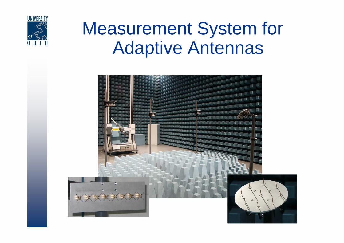
Measurement System for Adaptive Antennas
Measurement System for Adaptive Antennas
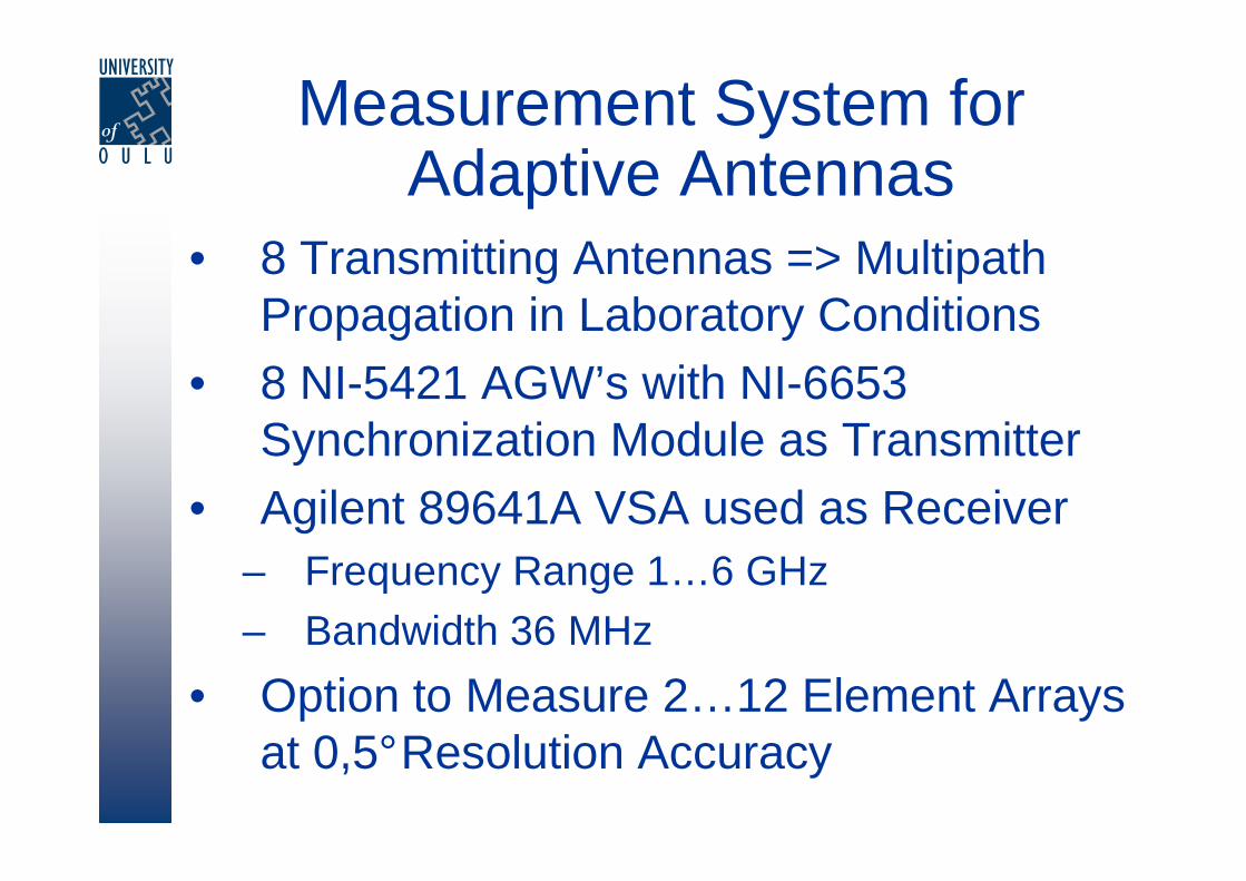
• 8 Transmitting Antennas => MultipathPropagation in Laboratory Conditions
• 8 NI-5421 AGW’s with NI-6653 Synchronization Module as Transmitter
• Agilent 89641A VSA used as Receiver– Frequency Range 1…6 GHz– Bandwidth 36 MHz
• Option to Measure 2…12 Element Arrays at 0,5°Resolution Accuracy
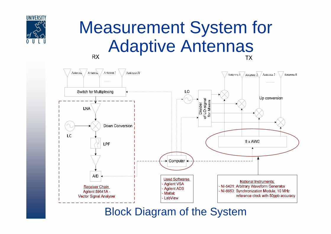
Block Diagram of the System
Measurement System for Adaptive Antennas
Microelectronics and Material Physics Laboratories
-35
-30
-25
-20
-15
-10
-5
01700 1800 1900 2000 2100 2200
Frequency / MHz
Att
enua
tion
/ dB
Fabrication
0.2 mm
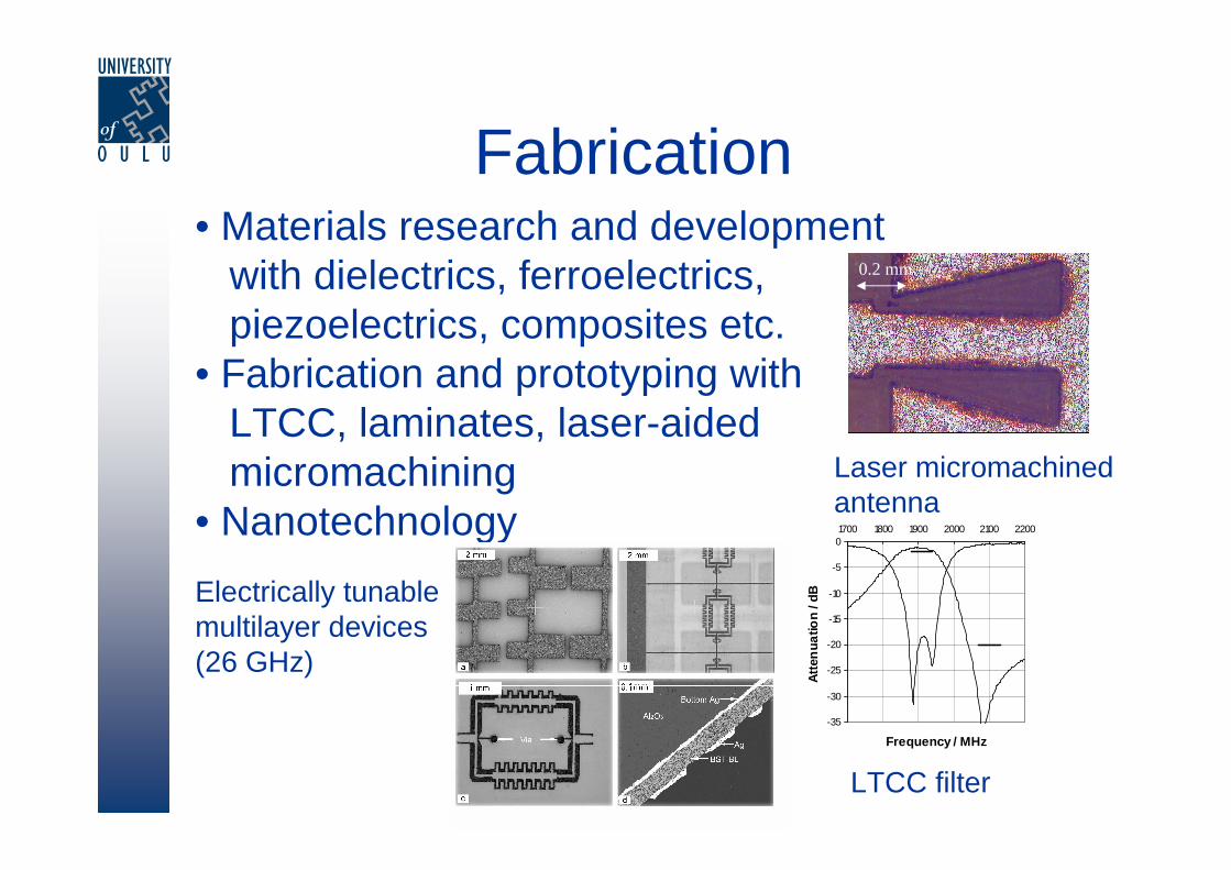
• Materials research and developmentwith dielectrics, ferroelectrics, piezoelectrics, composites etc.
• Fabrication and prototyping withLTCC, laminates, laser-aidedmicromachining
• NanotechnologyLaser micromachinedantenna
Electrically tunablemultilayer devices (26 GHz)
LTCC filter
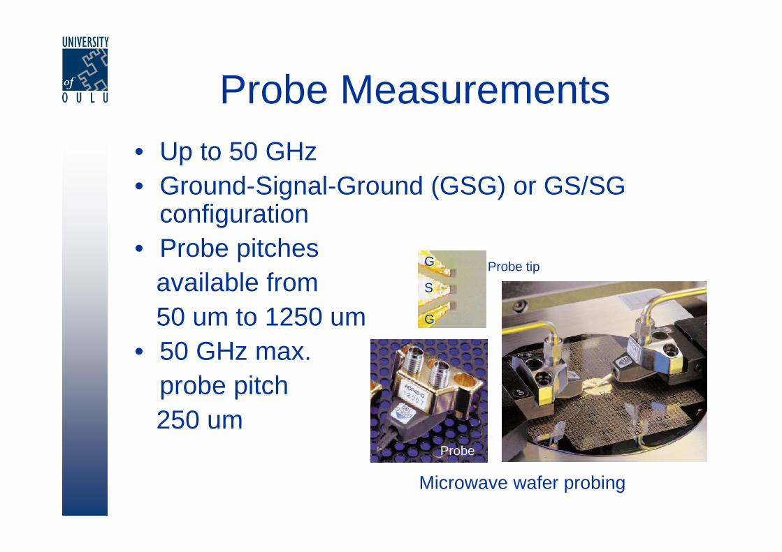
Probe Measurements• Up to 50 GHz• Ground-Signal-Ground (GSG) or GS/SG
configuration• Probe pitches
available from 50 um to 1250 um
• 50 GHz max. probe pitch 250 um
Microwave wafer probing
G
G
S
Probe tip
Probe
Other Measurements
• Impedance analyser up to 3 GHz• Electrical field assisted tunablity
measurements (max. 200 V)• LCR for low frequencies• Several characterization methods for
evaluation of components (ND and D) like acoustic, x-ray and electron microscopy
Softwares Used in Research
• Telecommunication System Simulators– CoCentric System Studio (CSS)– Optimized Network Engineering Tool (OPNET)
• Circuit Simulators– APLAC
– Agilent Advanced Design System (ADS)
• Signal Analyzing Sofware– Agilent Vector Signal Analyser (VSA)
• Electromagnetic Simulators– Ansoft High Frequency Simulators
• HFSS – Based on Finite Element Method (FEM)• Designer – RF & Microwave Design, RFIC Verification
– CST – Based on Finite Difference Time Domain (FDTD)
– SuperNEC - Based on Method of Moments (MoM)
• Other Software– LabView– Matlab / Simulink

Contact Information
• Optoelectronics and Measurement Laboratory– Raimo Saarimaa, Reservation of Measurement Facilities– Email: [email protected]– Tel: +358 8 553 2752
• Telecommunications Laboratory– Pekka Nissinaho, Information Concerning Antenna Measurements– Email: [email protected]– Tel. +358 8 553 2828
• Microelectronics and Material Physics Laboratories– Antti Uusimäki, Reservation of Manufacturing Facilities– Email: [email protected]– Tel: +358 8 553 2713