rf radiation safety for broadcasters · rf radiation safety for broadcasters ©2013 rf safety...
TRANSCRIPT

P.O. Box 10866 ● Southport, North Carolina tel: 910-253-0772 ● fax: 910-253-9226
e-mail: [email protected] www.RFSafetySolutions.com www.RFSafetyTraining.com
RF Radiation Safety For Broadcasters
©2013 RF Safety Solutions LLC Southport, North Carolina This presentation is copyrighted and intended for the use of the Society of Broadcast Engineers (SBE). No right to distribute copies publicly for sale, rental, lease, and lending or to third parties outside of the SBE is authorized.
Presented by Richard Strickland
July 24, 2013

1
RF Radiation SafetySources, Biological Effects, Standards,
and Safe Work Practices
Topics• Overview• Sources of RF energy• Biological effects• Standards• Potential hazards• RF Hazard Protection Equipment• RF Safety Signs

2
Overview of RF Safety Issues
• RF energy can cause excessive body heating if a person is exposed to relatively high concentrations of energy as occurs inside a microwave oven.
• Exposure to RF energy below the threshold has no impact on the body—the body deals with tiny amounts of heat from RF in the same way it adjusts to temperature changes.
Overview of RF Safety Issues
• RF energy can cause shocks and burns at low frequencies, such as near AM radio stations and HF communications antennas.
• The eyes are especially vulnerable to concentrated levels of RF energy at microwave frequencies. Waveguide leaks are a significant hazard for anyone in close proximity to the site of the leak.

3
Job Site Hazards
• FM Radio and TV Broadcast Antennas• Wireless Communications Antennas
– Cellular & PCS– Fire, police, emergency, and other 2-way antenna
systems such as SMR– Paging systems
• AM Radio Antennas• High-Power Microwave System Antennas
– Satellite uplink– Weather radar
• Waveguide Leaks (eye hazard)
Potentially Hazardous Locations
• Towers– All FM radio and TV installations– Wireless systems at the same elevation as omni-
directional antennas and in front of sector antennas
• Rooftops– Wireless systems antennas– FM radio antennas– Satellite-uplink antennas

4
Potentially Hazardous Locations
• Ground– Near waveguide should it be open or leak– AM detuning networks
• AM Antennas– Serious burn hazards at tower, feed line, and inside
tuning huts– Induced and contact currents when on tower
• High-Power Waveguide Systems– Potential eye hazard within 3 feet of any junction or
section of flexible waveguide if there is a leak
Radio and Television

5
AM Stations
Rooftop Wireless Antennas
6
Responsibilities & Liabilities
• As a licensee regardless of where the emitter is located—your own property or a shared site like Mt. Wilson, Sutro Tower, or Sears Tower.
• As an employer.• As a company that hires contractors.• As a company that has visitors.
Electromagnetic Radiation
Electromagnetic radiation covers the entire spectrum from RF radiation to
cosmic rays.

7
Types of Radiation
• Radio Frequency (RF) energy and the energy from most of the light frequencies is a form of non-ionizing radiation. It is distinctly different from ionizing radiation. The primary concern with non-ionizing radiation is tissue heating.
• Ionizing radiation can be very dangerous. The most common sources are from X-ray equipment and radioactive materials that product gamma rays. Ionizing radiation can cause damage to DNA.
Non-Ionizing RadiationMechanism of injury: Tissue heating and burns
• The primary concern with RF radiation is tissue heating. Effects are not cumulative.
• Shocks and burns are a concern at the lower RF frequencies, for example, at an AM tower site.
Ionizing RadiationMechanism of injury: Permanent biologicalchanges to molecular structure. Effects arecumulative.
Forms of Radiation Summary

8
Radiation is the term that pertains to the emission and propagation of electromagnetic energy in the form of waves. It can be characterized by frequency, wavelength, or energy.
• Frequency is the number of times per second a peak occurs (cycles per second or Hertz).•Wavelength is the distance between two peaks of the wave.•Energy is proportional to frequency.
Electromagnetic Radiation
Electromagnetic Energy
• Electromagnetic energy all travels at the speed of light (light is just one form of electromagnetic energy). The speed of light is 300 million meters per second.
• Electromagnetic radiation includes the radio frequencies (RF), light, X-rays, gamma rays (from radioactive materials), and cosmic rays found in space.

9
Defining an Electromagnetic Wave
• Frequency—most common definition for people working in electronics
• Wavelength—most common way of defining light frequencies, also used in electronics
{λ (meters) = 300/f (MHz)}
• Energy—most common way of defining the higher “frequency” sources of energy such as X-rays and gamma rays {E(energy) = h x f, where “h” is a constant}
When there is sufficient energy to change the molecular structure of the absorbing matter by removing one of more electrons, creating an electrically charged particle (ion).
Ionizing Radiation
IONIZATION

10
Ionizing Versus Non-Ionizing
• Electromagnetic energy at frequencies above UV light is “ionizing,” i.e. photons have enough energy to tear electrons from their atoms, creating ions. This can cause permanent biological changes to the molecular structure of cells. UV-C light is also a form of ionizing radiation, which is the reason for concern about the loss of ozone, which blocks UV light.
• The primary concern with RF (non-ionizing) radiation is tissue heating.
• Shocks and burns are a concern at the lower RF frequencies.
Frequency, Hertz1050 1012 1014 1015 1017 1020 1024
ELF fields
Radio Waves Infrared Ultra-Violet X-Rays
Gamma & Cosmic
Rays
Non-ionizing Radiation Ionizing Radiation
VisibleLight
A B
UV-C
Ionizing Versus Non-Ionizing
• Effects of non-ionizing radiation are notcumulative.
• Effects of ionizing radiation are cumulative.
January February March April May June July August September October November December
Non-Ionizing Radiation
Ionizing Radiation
11
Biological EffectsRadio Frequency Energy and
the Human Body
RF Energy & the Human Body
• Research conducted in the 1960s and 1970s revealed that a human body functions as an antenna when exposed to RF energy.
• There are several variables that determine how effective an antenna you are.
• The better an antenna you are, the more energy you absorb.

12
RF Energy & the Human Body
• The major concern with exposure of the entire body to significant levels of RF energy is heating.
• The amount you heat primarily depends on two factors:
1. The intensity level of the RF field that you are exposed to.
2. How much of the energy you absorb which varies with how effective an antenna you are.
The Human Body as an Antenna
• The three factors that are most important in determining how effective an antenna you represent are:
§ Your height versus the frequency/wavelength.
§ Your position versus the polarization of the field. You absorb the most when your orientation matches the field. Most wireless systems have vertical polarization which aligns well with a person that is standing.
§ How well grounded you are.

13
Energy Absorption Versus Frequency
• Average-sized adults absorb the most energy (i.e. make the best antennas) in the frequency range of about 75 to 95 MHz (TV Channels 5 & 6 and FM radio).
• If you are well grounded, you make a good antenna at half the frequency.
• A well-grounded average-size adult makes a very good antenna at about 42 MHz.
Ch. f (MHz) Ht.
6 82-88 5’9”
5 76-82 6’2”
4 66-72 6’11”
Basic Antennas
• Dipole antennas are very common, somewhat directional antennas.
• The length of a dipole antenna is typically a little less than half a wavelength (λ/2). Dipole antennas are not grounded.
• A quarter-wave antenna is grounded at one end. It is resonant at half the frequency of a dipole of the same dimensions.

14
The Human Body as an Antenna
• Under most conditions, you function as a lossy, wide dipole antenna. (You are lot less conductive and much wider than a thin metal rod!)
• If you are grounded, your body becomes a quarter-wave antenna.
• Quarter-wave antennas work best at half the frequency of a dipole of the same length.
Thin, losslessdipole antenna
2-3 Ohms
Wide, lossy body
~360 Ohms
Human Body as a Dipole
• Because of a person’s width—even somebody that is very thin is wide compared to a metal rod—and the relatively high impedance compared to a metal antenna, a person is a low Q antenna with a relatively wide bandwidth.

15
Specific Absorption Rate (SAR)
• The rate of absorption of energy into the body.
• The method used to quantify the effects of electromagnetic fields on the body.
• The basis for all modern standards.
SAR measured in W/kg
Specific Absorption Rate
• SAR is used not only to quantify heating due to exposure to RF energy, but also to quantify internally generated heat from exercise.
• RF heating causes effects that are very similar to overexertion.
• All major standards set the maximum heat allowed from RF heating to an SAR level of 0.4 W/kg. This is 10% of what is considered tolerable under the best of conditions.
16
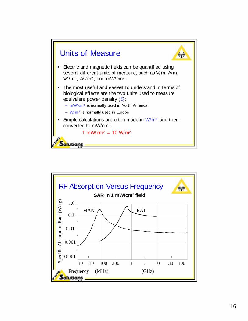
Units of Measure• Electric and magnetic fields can be quantified using
several different units of measure, such as V/m, A/m, V²/m², A²/m², and mW/cm².
• The most useful and easiest to understand in terms of biological effects are the two units used to measure equivalent power density (S):– mW/cm² is normally used in North America
– W/m² is normally used in Europe
• Simple calculations are often made in W/m² and then converted to mW/cm².
1 mW/cm² = 10 W/m²
RF Absorption Versus Frequency
10 30 100 300 1 3 10 30 100Frequency (MHz) (GHz)
1.0
0.1
0.01
0.001
0.0001
Spec
ific A
bsor
ptio
n R
ate
(W/k
g)
MAN RAT
SAR in 1 mW/cm² field

17
RF Absorption Versus Frequency
10 30 100 300 1 3 10 30 100Frequency (MHz) (GHz)
1.0
0.1
0.01
0.001
0.0001
Spec
ific A
bsor
ptio
n R
ate
(W/k
g)
MAN RAT
SAR in 1 mW/cm² field
~10:1
SAR Versus Frequency
E - Polarization
H - Polarization
K - PolarizationE
K
H
Antenna
Radiation
Frequency10 30 100 300
(MHz) (GHz)
Spec
ific
Abs
orpt
ion
Rate
(W/k
g)
.0001
.001
.01
0.1
1.0
SAR Induced in a 1.75m high Human Exposed to a 1 mW/cm2 RF Field
1 3 10 30 100

18
Whole Body Resonance
Where λ (m) = 300/f (MHz); assumes a dipole = λ/2
Subject Ht (m) Ht (in) fR (Isolated) fR (Grounded)
Adult male 1.75 69 86 MHz 43 MHz
NBA player 2.29 90 66 MHz 33 MHz
Infant 0.5 20 300 MHz 150 MHz
SAR Versus Frequency
10 30 60 100 300 600 1,000
1.0
Numerical Calculationsbased on a block modelof man in conductivecontact with ground
One year old childin conductivecontact with ground
Prolate model ofa human infant
Frequency (MHz)
Ave
rage
SA
R (W
/kg) 0.3
0.1
0.03
0.01
0.003
0.001
Upper limit for the range of human beings from infant to adult

19
SAR Is Not EverythingOther important biological concepts include:
–Time averaging—the most critical concept–Spatial averaging–Partial-body heating–Penetration depth
Time Averaging
• Because the primary effect is thermal, exposure is averaged over time.
• People can take very short term exposure to extreme cold or heat that they cannot otherwise tolerate.
• In most standards the averaging time is six minutes, which is close to the thermal regulatory response time of the human body.

20
Spatial Averaging
• Measurements are averaged over an area equivalent to the vertical cross-section of the human body.
• Although this diagram shows the field levels from a collinear dipole array, typical of wireless antennas, the RF field levels in the reactive near field of a parabolic reflector antenna also varies by up to 6 dB (4:1).
Spatial Averaging TechniqueSpatial averaging is typically accomplished by moving the probe (sensor) in a vertical line from the ground to roughly 6 feet above ground while a timer is running.
Typically 32 samples are collected per second so a 10-second pass yields about 300 tightly-spaced readings that are averaged by the meter.

21
Partial-body Heating• Partial-body heating is important under some
conditions. There are different resonant frequencies for your whole body, your head, and your eyes.– Your head makes a very good cell phone antenna.– Your eyes make very good microwave-band
antennas.
• The limbs can tolerate higher levels since the body’s circulatory system acts as a coolant with the remainder of the body functioning as a radiator. (typically 20:1 higher).
• The basic limits apply for the eyes and testes due to the poor blood flow of these organs.
Penetration Depth Versus Frequency
§ The higher the frequency, the shallower the penetration, regardless of the material.
§ You tend to sense shallow penetration because that is where your nerves are. You tend not to notice deep penetration from lower frequencies.
0.1 1.0 100.3 3.0 GHz
Fat
70605040302010
7654321
Mus
cle
Depth in cm.

22
SAR Versus Metabolic Rate
• How much heat can a body absorb before adverse affects are felt?
• At what levels can permanent biological damage occur?
Typical SAR Levels
Activity Level SAR Level
Sleeping 1 W/kg
Fast Walk/Light Run 2.0-2.5 W/kg

23
Specific Absorption Rates (SAR)
*Watts per kilogram of body mass.
SAR Level*
Situation/Limit
5.0 Permanent damage can occur with whole body heating.
4.0 At this level, people feel ill but the effects are not permanent.
0.4 FCC limit for Occupational/Controlled exposure (10:1 safety factor).
0.08 FCC limit for General Population/Uncontrolled exposure.
1.6 Cell phone limit for the head.
Why a 10:1 Safety Factor
• Rate assumes room temperature—if RFR exposure occurs at high temperature, the body already has a thermal load.
• Hot spots can occur within the body, especially in the human resonance range.
• Not everyone is young or healthy.
• The individual may be engaged in a physically stressful task, such as climbing a tower, that generates heat by itself.

24
Overexposure Symptoms*
As time and/or energy level (intensity) increases, an individual is likely to experience:
• First, an overall feeling of warmth; and• Then, symptoms similar to overexertion (perspiration,
elevated body temperature, labored breathing).• Some symptoms (nausea, headache) are often mistaken
for the flu. Many people report getting a metallic taste in the mouth.
• Severe cases have the same effects as heatstroke.
*From significant levels of RF energy
Permanent Damage
• Permanent biological damage can occur when cells are destroyed.
• Human cells begin to die at a temperature of 107° Fahrenheit. This is the reason people with high fevers are often packed in ice if the temperature goes too high.

25
Permanent Damage
• If a small percentage of the cells in an organ are damaged, the body often repairs itself.
• If the damage is extensive, then the damage becomes truly permanent.
Eye Damage
• Exposure to RF an RF field level of 50 mW/cm² for 10 minutes has been documented to cause cataracts.
• Higher levels of RF energy can cause severe eye damage. One well-documented case at Johns Hopkins resulted in the loss of both color vision and night vision after a 10 minute exposure to a waveguide leak.
26
Medical Implants
• If you have a medical implant with electronic circuitry, it may be vulnerable to electromagnetic interference in RF fields.
• Devices such as cardiac pacemakers, medical monitoring equipment, and pumps may malfunction at field levels farbelow the FCC MPE exposure limits.
Medical Implants
• If you have a medical implant with electronic circuitry:• Ask your doctor for his permission to work at an
RFR site and what symptoms you might exhibit should your implant malfunction.
• Advise your health and safety manager that you have a medical implant, what advice your doctor recommends regarding working in an RFR site, and what symptoms you might present if it should malfunction. People should be able to recognize the symptoms if you experience a problem.
27
Standards & Regulations
The communications industry in the United States must comply with the
Federal Communications Commission (FCC) Regulations that cover RF radiation safety.
Compliance Requirements
Stations must:
• Comply with FCC Regulations for public areas.
• Comply with FCC Regulations regarding employees and contractors.
• Comply with OSHA Regulations regarding employees.

28
First Standard Based on SAR
MHzkHz GHz
ANSI C95.1-1982. Adopted by the FCC in 1986
0.01 1 3 10 30 100 300 1 3 10 30 100 3003 10 30 100 300
0.1
1.0
10100
104
105106
900/f2
f/300E&H
mW/cm2
103
Radiation ProtectionGuide
Time and Whole BodyAveraged
f in MHz100.0
5.01.0
First Standard Based on SARANSI C95.1-1982. Adopted by the FCC in 1986
0.01
MHz1 3 10 30 100 300 1 3 10 30 100 3003 10 30 100 300
kHz GHz
0.1
1.0
10100
104
105106
900/f2
f/300E&H
mW/cm2
103
Radiation ProtectionGuide
Time and Whole BodyAveraged
f in MHz
SAR curves:Grounded man
Ungrounded infant

29
First Standard Based on SARANSI C95.1-1982. Adopted by the FCC in 1986
0.01
MHz1 3 10 30 100 300 1 3 10 30 100 3003 10 30 100 300
kHz GHz
0.11.010
100
104105
106
E&H
mW/cm2
103
Radiation ProtectionGuide
Time and Whole BodyAveraged
f in MHz
<0.4 W/kg thermal heating
Limit based on electrostimulation due to strength of E-field
FCC 1997 Regulations1,000
47 CFR 1.1310 Radio-frequency Maximum Permissible Exposure (MPE) limits
1 3 10 30 100 300 1 3 10 30 100 300 3 10 30 100 300
= Occupational/Controlled Exposure= General Population/Uncontrolled Exposure
0.1
1.0
10
100
E & H Fields
GHzMHzkHz
mW
/cm
2

30
FCC MPE Limits for Radio and TV
Exposure FM/VHF TV AM Time Average
Occupational 1.0 mW/cm² 100 mW/cm² 6 minutes
General Population 0.2 mW/cm² 100 mW/cm² Not allowed
Qualifying to Use Occupational Limits
• Company should be operating under an RF safety program.– Workers must be fully aware and able to
exercise control over their exposure to RF fields.
– Access must be limited to those only workers (defined above).

31
RF Safety Zones
• Green Zone: RF field levels are below FCC MPE limit for General Population/Uncontrolled (public) exposure. Anybody can be here at any time.
• Yellow Zone: RF field levels are above public MPE limit but below FCC MPE limit for Occupational/Controlled (occupational) exposure. Only workers that are fully aware and can exercise control can be here.
• Red Zone: RF field levels are above occupational MPE limit. Time averaging must be used unless power is reduced. This distance is ~1 ft. to
10 ft. for typical wireless omnidirectional antennas.
Fully Aware Workers
The phrase fully aware refers to workers who:• Have received both written and verbal
information regarding RF radiation.• Have received training that includes how to
control or mitigate RF radiation exposure.

32
Workers Who can Exercise Control
The phrase exercise control refers to workers who:
• Understand how to use administrative controls and engineering controls to reduce their exposure level. These controls include time averaging, RF personal monitors, and RF protective clothing.
FCC 1997 Regulations1,000
47 CFR 1.1310 Radio-frequency Maximum Permissible Exposure (MPE) limits
1 3 10 30 100 300 1 3 10 30 100 300 3 10 30 100 300
= Occupational/Controlled Exposure= General Population/Uncontrolled Exposure
0.1
1.0
10
100
GHzMHzkHz
mW
/cm
2
•Access Restricted to trained personnel
•Time averaging and/or power reduction required.
•Open to all individuals without limitation.
•Access Restricted to trained personnel
33
FCC Regulations & Time Averging
• The MPE limit for Occupational/Controlled exposure is based on any 6-minute period of time.
• The MPE limit for General Population/ Uncontrolled exposure is an instantaneous limit, i.e. time averaging is not allowed.
NOTE: The FCC’s point of view is that if you have untrained (not fully aware or able to exercise control) people in an uncontrolled environment or situation, the people do not know how to use time averaging.
FCC Five Percent Rule
• The FCC can and has issued Notices of Apparent Liability (NALs) and subsequent fines where multiple licensees combine to exceed the MPE limit for an area:– Mt. Wilson: 3 FMs and a TV station– Park Tower Building in Tampa: an FM and a TV station
• Any station that contributes more than 5% of the applicable MPE limit* is equally guilty.– Park Tower: $25k for TV station and $20k for the FM.– Mt. Wilson: one FM was at 80% of MPE limit while the
other 3 where deemed to be 10 to 12%. Each station was fined $10k, even though one station contributed far more.
* Public or occupational limits

34
Antenna Characteristics
Low gain antennas are more dangerous than high gain antennas!
Antenna Gain
• Antenna gain is a measure of the antenna’s ability to focus energy.
• Gain becomes important in the far field of an antenna.
• The distance from the antenna to where the far field begins depends on the design of the antenna and the frequency.
– It is about 8 to 20 feet for most wireless antennas.– It ranges from 75 feet to thousands of feet for
typical satellite-uplink antennas.

35
Field Intensity versus Distance
• Far Field: Energy in the far field drops off inversely as the square of the distance. In other words, at twice the distance, the intensity is spread out over 4 times the area so the intensity is ¼ as strong. At 10 times the distance, the level is down to 1%.
• Radiating Near Field. The energy drops off linearly with distance. At twice the distance, the energy level is ½, not ¼ as it would be in the far field.
Antenna Designs
• The majority of antennas that you are likely to encounter fall into two categories. If you understand the characteristics of these antennas, you should be able to understand the potentially hazardous locations near these antennas.
– Reflector antennas are used in satellite uplink antennas such as SNG trucks, point-to-point microwave systems, and radar antennas.
– Collinear dipole array antennas are used in most wireless systems, FM radio, and television broadcast. There are directional and omni directional versions of these antennas. Directional antennas are used on all cellular towers.
36
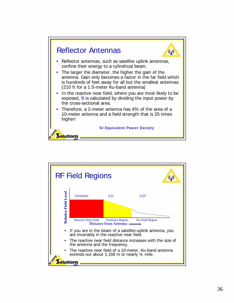
Reflector Antennas• Reflector antennas, such as satellite uplink antennas,
confine their energy to a cylindrical beam.• The larger the diameter, the higher the gain of the
antenna. Gain only becomes a factor in the far field which is hundreds of feet away for all but the smallest antennas (210 ft for a 1.5-meter Ku-band antenna)
• In the reactive near field, where you are most likely to be exposed, S is calculated by dividing the input power by the cross-sectional area.
• Therefore, a 2-meter antenna has 4% of the area of a 10-meter antenna and a field strength that is 25 times higher!
S=Equivalent Power Density
RF Field Regions
• If you are in the beam of a satellite-uplink antenna, you are invariably in the reactive near field.
• The reactive near field distance increases with the size of the antenna and the frequency.
• The reactive near field of a 10-meter, Ku-band antenna extends out about 1,168 m or nearly ¾ mile.
Reactive Near Field Transition Region Far Field Region
Rel
ativ
e Fi
eld
Leve
l
Distance from Antenna
Constant 1/D 1/D²
37
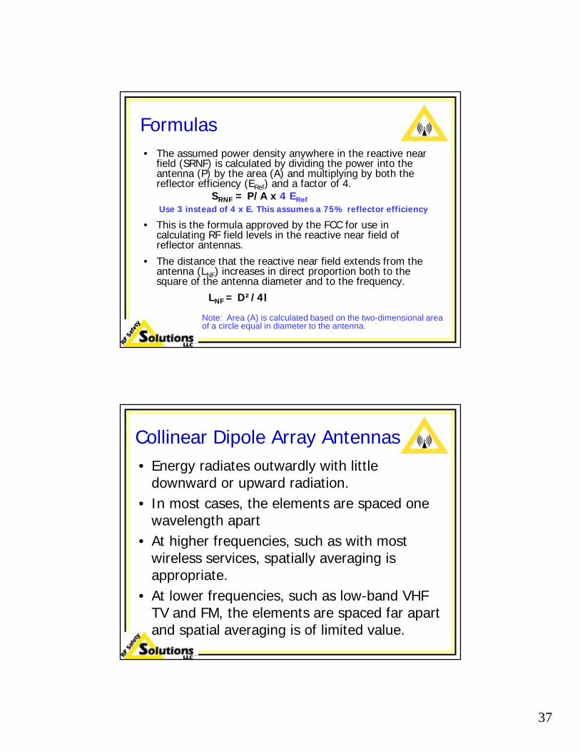
Formulas• The assumed power density anywhere in the reactive near
field (SRNF) is calculated by dividing the power into the antenna (P) by the area (A) and multiplying by both the reflector efficiency (ERef) and a factor of 4.
SRNF = P/A x 4 ERefUse 3 instead of 4 x E. This assumes a 75% reflector efficiency
• This is the formula approved by the FCC for use in calculating RF field levels in the reactive near field of reflector antennas.
• The distance that the reactive near field extends from the antenna (LNF) increases in direct proportion both to the square of the antenna diameter and to the frequency.
LNF = D²/4λ
Note: Area (A) is calculated based on the two-dimensional area of a circle equal in diameter to the antenna.
Collinear Dipole Array Antennas • Energy radiates outwardly with little
downward or upward radiation.• In most cases, the elements are spaced one
wavelength apart• At higher frequencies, such as with most
wireless services, spatially averaging is appropriate.
• At lower frequencies, such as low-band VHF TV and FM, the elements are spaced far apart and spatial averaging is of limited value.

38
Collinear Dipole Array Antennas
• Dipoles are stacked vertically with a center-to-center distance of one wavelength.
• Standard dipoles are used inside typical wireless omnidirectional and panel antennas that have covers.
• Folded dipole and lower frequency antennas usually are not covered.
Folded dipole array and single folded dipole
Dipole Radiation Pattern
• Dipoles have very little downward or upward radiation when mounted vertically as they are with all panel and omni antennas.
• Folded dipole antennas have very similar radiation patterns. The major difference is that they have a broader bandwidth.

39
Dipole Array Radiation Pattern
Estimating Field Strength
• The spatially-averaged field strength that you may be exposed to can be calculated using the “cylindrical model”.
• It is appropriate for all typical co-linear dipole array antennas, both omni-directional whip antennas, and directional or sector antennas.
• The method is very accurate for situations where you are at the same elevation as the antenna.
• The method is appropriate in the near field of the antenna, typically 8 to 15 feet for most wireless antennas.

40
Cylindrical Model
• Although the energy close to the antenna has peaks and nulls, the spatial average can be represented by a cylinder equal in height to the antenna and with a radius equal to your distance from the antenna.
Effect of Antenna Size6-foot antenna:
An adult at the same elevation is illuminated by all the energy in his/her direction.
12-foot antenna:
An adult at the same elevation is illuminated by half of the energy in his/her direction. Although the gain is higher, close (<15 feet) to the antenna, the RF field level is half of that from a 6-foot antenna with the same input power level.

41
Cylindrical Model Calculations
H = height of antennaD = distance from antennaA = area of surface of cylinder.
Ends are ignored since there is very little upward or downward energy.
A = 2 R x H (where the radius is equal to the distance “D” from the antenna.
D
H
Typical Calculations
• A = 2 x 1 x 1.8 with a person 1 meter away from a 6-foot omni antenna. Therefore, the area is 11.3 m²
• S = P/A so if the input power to the base of the antenna is 300 Watts:
S equals 26.5 W/m² = 2.65 mW/cm²
• If it is a sector antenna:– Multiply by 3 for a typical 120° tower antenna– Multiply by 4 for a typical 90° rooftop antenna
S = equivalent power density measured in W/m²

42
Safe Distance Analysis
• The worst case antennas are 6 feet high and operate in the VHF band, typical of many 2-way radio and SMR systems. These antennas are mounted at roof level.
• The two plots show the RF field levels from 6 ft. omnidirectional and 90 degree sector antennas operating at 150 MHz with 400 Watts input.
•Red areas exceed Occupational/Controlled limits
•Yellow areas exceed General Population/Uncontrolled limits.
•Grid lines on 10 ft. centers.10’ 20’
Effects of Beam Width
120 degrees 90 degrees
60 degrees 30 degrees
Four 4-foot 850 MHz antennas with 350 Watts input

43
Effects of Elevation• The plots on the next slide are all of a typical 6-
foot high cellular 90 degree sector antenna with an input power level of 400 Watts. The difference is the elevation of the base of the antenna. When it is at 0 feet, you are directly opposite the antenna.
• Legends:– Areas in red have spatially averaged fields that
exceed the occupational MPE limit.– Areas in yellow exceed the public MPE limit but are
below the occupational limit.– Areas in green are below the public limit.– Grid lines are 10 feet apart.
Effects of Elevation
0 feet 6 feet 10 feet
Height of base of antenna relative to the place that you are standing
44
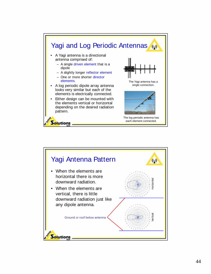
Yagi and Log Periodic Antennas• A Yagi antenna is a directional
antenna comprised of:– A single driven element that is a
dipole– A slightly longer reflector element– One or more shorter director
elements.• A log periodic dipole array antenna
looks very similar but each of the elements is electrically connected.
• Either design can be mounted with the elements vertical or horizontal depending on the desired radiation pattern.
The log periodic antenna has each element connected.
The Yagi antenna has a single connection.
Yagi Antenna Pattern
• When the elements are horizontal there is more downward radiation.
• When the elements are vertical, there is little downward radiation just like any dipole antenna.
Ground or roof below antenna

45
Job Site Hazards
Broadcaster Check List
• Broadcast transmission antennas: On tower is always a hazard for FM, TV, and AM. Ground level is rarely a safety issue except for AM but can be a compliance issue.
• Rooftops where you may have repeaters and/or cameras can have high RF field levels.
• SNG trucks: antennas and potential waveguide leaks.
• Weather radar: potential waveguide leaks.
Potential RF exposure areas and equipment:

46
Tower Climbing is the Major Risk
• Personal monitors should be used by anyone climbing a tower with TV or FM antennas on it or on nearby towers.
• Power reduction is often needed but even when systems are shut down there is always the danger that the systems will be turned back on. It has happened countless times.
• Many towers with wireless services antennas can have high RF fields at certain elevations.
Broadcast Antennas
• FM radio and television antennas generate veryintense RF field levels. The high field levels can extend out hundreds of feet in front of the antenna.
• There are often very high RF fields directly below these antennas. Some broadcast sites have significant RF field levels on the ground.

47
Broadcast Hazard Zones• Unless you are wearing an
RF personal monitor, do not climb within 50 feet of the bottom of an FM radio or television broadcast antenna that is located above you on the same tower.
• Do not climb within 100 feet of the elevation of bottom of an FM or TV antenna on a nearby tower unless wearing a monitor or the towers are separated by at least 500 feet.
FM Radio or TV Antenna
50’
<500 feet
100’
AM Stations
• AM stations can generate very high RF field levels, especially near the base and under wide-spaced self-supporting towers. RF burns are a very serious concern.
• They a can occur if you touch the tower or the feed. Remember that at an AM station, the tower is the antenna!

48
AM Stations• There are three RF safety concerns associated with AM
towers:1. Burns: Touching the tower, feed line, or the
tuning circuits can result in very serious burns.2. Induced and Contact Current: If you climb
the tower, current will flow through your body. Extremely high SAR levels can occur in the wrists and ankles and cause serious joint damage.
3. High Field Strengths: Although the human body is not an effective antenna at AM frequencies, the area near the base of towers should be avoided due to the very high field strengths, if for no other reason than compliance with FCC Regulations.
Climbing AM Towers
• Climbing hot AM towers is not recommended if the power in the tower is more than 500 Watts. Even at 500 Watts, there is a risk. The level of risk at a fixed power level is dependent on several factors, especially frequency and tower height. Shorter towers and higher frequencies are worse.
• In addition to the burn hazard, there is a risk of the climber being subjected to very high induced current levels, especially in the wrists and ankles. In essence, the climber becomes part of the antenna and current flows through his or her body.

49
Climbing Adjacent AM Towers
• Even climbing a deenergized tower in a directional array (or one that is close to other stations) you can still experience severe shocks and burns as well as induced currents while on the tower.
• In the absence of specific modeling, do not climb an adjacent tower when the hot tower is energized by more than 5 kW.*
• Modeling is highly recommended.*Computer models developed by Tom Jones of Carl T. Jones Corp.
Procedure* for Adjacent Towers
• When climbing an indirectly energized tower in an array, i.e. the energy is being received, not fed from the transmitter:
1. Short the tower to allow people to get on or off so that the shock and burn potential is eliminated.
2. Once everyone is on the tower, it is strongly recommended that the tower be detuned to reduce the amount of induced current.
3. Short the tower when exiting.*Procedure recommended by Tom Jones

50
Using Cranes near an AM Station
• Cranes make good AM radio antennas. • The amount of energy that they pick up at a given
location is highly dependent on the elevation angle and the direction that the crane is pointing.
• It is very possible to have high RF voltages on the hook of the crane at distances up to 2 km from a high power AM station.
• If you experience this problem, a Kevlar or nylon strap should be used to insulate the crane hook from the load.
Folded Unipole AM Antennas
• This design is often used where an FM antenna is mounted on the top of the tower.
• The broadcast element is made up of a series of wires parallel to the tower structure.
• There is a ring near the bottom of the tower where the vertical wires are connected. If you touch this ring you will get burned!
• The AM system must be turned off when climbing the tower!

51
Satellite-Uplink Antennas
• Generally not a hazard except for maintenance personnel that may get close to the feed horn and/or sub-reflector or a waveguide leak.
• Smaller antennas, such as on SNG trucks and especially portable uplink antennas, are far more dangerous than larger, fixed uplinks.
Where LOTO is Critical!• This is not the type of work that
most broadcast personnel perform but it is a good example of where RF levels can be extremely high.
• Severe eye damage can occur within minutes when exposed to the extremely high levels of microwave frequency RF energy which can be present between the feed horn and the subreflector.
• Follow LOTO procedures.
• Wear RF personal monitor as a redundant safety measure.
The energy level between the feed horn and the subreflector is extremely concentrated.
Feed Horn
Sub reflector
52
Waveguide Leaks
• The eyes are particularly vulnerable because the limited blood flow provides limited circulatory cooling.
• Leaks, although not especially common, are acute problems that can occur at any time.
• Even a few watts of energy can be a concern if it is concentrated in a very small area.
• Energy drops off rapidly with distance—even two feet spacing is enough under most conditions with the equipment broadcast personnel are liable to encounter.
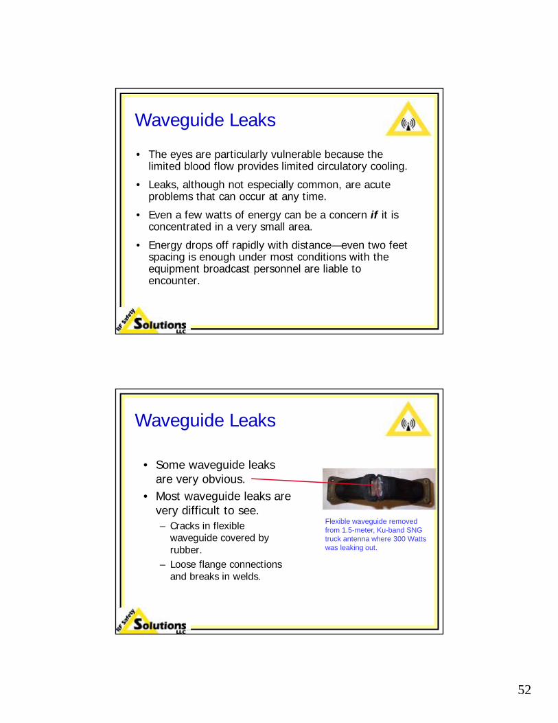
Waveguide Leaks
• Some waveguide leaks are very obvious.
• Most waveguide leaks are very difficult to see.– Cracks in flexible
waveguide covered by rubber.
– Loose flange connections and breaks in welds.
Flexible waveguide removed from 1.5-meter, Ku-band SNG truck antenna where 300 Watts was leaking out.

53
ENG Trucks
• RF field levels are insignificant anywhere below 8 feet above the ground, even with the mast at zero elevation, providing that the antenna is not pointed below horizontal.
• Antennas should never be pointed below the horizontal and energized.
• Personnel should never be on the roof of the truck or climb up the ladder with the antenna energized unless the mast is elevated at least 7 feet.
ENG Truck
• Very high RF field levels are present near the feed horn of the antenna.
• Never put your head near the radiating side of the feed horn.
54
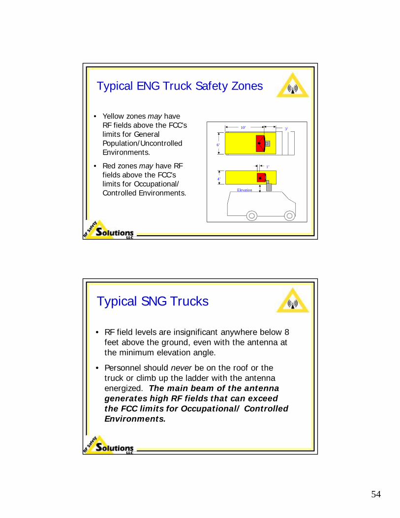
Typical ENG Truck Safety Zones
• Yellow zones may have RF fields above the FCC’s limits for General Population/Uncontrolled Environments.
• Red zones may have RF fields above the FCC’s limits for Occupational/ Controlled Environments. Elevation
Elevation4’
10’
6’
3’
1’
Typical SNG Trucks
• RF field levels are insignificant anywhere below 8 feet above the ground, even with the antenna at the minimum elevation angle.
• Personnel should never be on the roof or the truck or climb up the ladder with the antenna energized. The main beam of the antenna generates high RF fields that can exceed the FCC limits for Occupational/ Controlled Environments.

55
SNG Truck
• High RF fields are present in the main beam of the antenna.
• Extremely high fields are present near the feed horn.
• Never get in the main beam of the antenna.
SNG Truck Safety Zones
• Never get in the main beam of the antenna.
• Never aim the beam of the antenna at a building.
• Follow lock out/tag out procedures carefully.

56
Building Rooftops
• Broadcasters should consider where their news crews and technical personnel are deployed. Some rooftops—perhaps the one where your ENG repeater, camera, or radio system is located—are loaded with wireless services antennas.
• The RF exposure potential on rooftops can be significant.
Trends in Rooftop Antennas• Good News:
– There are very few paging antennas left, which used to be some of the worst systems.
– The cellular, PCS, and GSM antenna systems used today use far lower RF power levels than older systems.
• Bad News:– Terrestrial XM radio antennas used in major cities put
1000 Watts into omni antennas or 500 Watts into panel antennas
– Media Flo TV antennas, used for the Verizon Wireless V-cast system, are showing up on an increasing number of rooftops. These systems have up to 7,000 Watts of input power. (shut down in March’11)

57
Building Rooftops
1. Stay a minimum of 10 ft. from all omni-directional “whip” antennas and 20 feet from the radiating side of all directional “sector” antennas that are at the same elevation.
2. You can walk much closer to these antennas due to the effects of time averaging but unless you know more about the RF field levels, you should not remain close to these antennas.
3. If there is an FM broadcast antenna on the roof, do not go there without an RF personal monitor.
Typical PCS/Cellular Installation
Directional “sector” antennas are rated for coverage of either 90° or 120°. These are the half power beam widths. Assume that there is significant radiation throughout the forward hemisphere up to 20 feet distance.
58
Rooftop with Sector Antennas
• Rooftops that contain only sector antennas around the perimeter like this one do not have significant RF field levels.
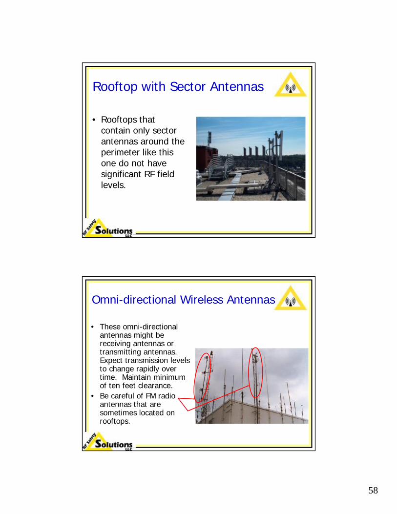
Omni-directional Wireless Antennas
• These omni-directional antennas might be receiving antennas or transmitting antennas. Expect transmission levels to change rapidly over time. Maintain minimum of ten feet clearance.
• Be careful of FM radio antennas that are sometimes located on rooftops.

59
Radiation Pattern of Sector Antennas
• Sector antennas radiate only in the forward position.
• Rooftop antennas are typically rated at 90° (most of the energy is ±45° of the centerline with only a slight downward tilt (<4°).
• Most tower antennas are rated at 120° with a similar downward tilt.
Top View
Side View
Radiation Pattern of Omni Antennas
• Omni-directional antennas radiate over 360° in azimuth with only a very slight amount of downward radiation.
• If the base of the antenna is at least 1 foot above your head (or ~7 feet above the roof) it is safe to walk up to it. This is because in order to be in the beam of the energy one must be several feet away where the field is weak.
Top View
Side View

60
Safe Distance Analysis
• The minimum distances of 10 feet from a whip antenna and 20 feet from a sector antenna are worst-case because:– The analysis assumes that the antennas are operating
at VHF frequencies, like many two-way radios and the antennas are 6 feet or shorter.
– Taller antennas and those systems operating at cellular, most paging, and PCS frequencies are result in a lower exposure in terms of MPE
Omni-directional Wireless Antennas
• This is one of the “horrible examples” of RF hazards on building rooftops. These are all omni-directional antennas and it impossible to avoid them while on the roof. You should not go onto a roof like this without wearing an RF personal monitor. This roof even has an FM antenna!

61
Point-to-Point Microwave Antennas• These are highly
directional, low power (1-2 Watts) microwave point-to-point systems. They are normally* not an RF hazard even when directly in front of them.
• For example, a 4-foot antenna with an input power of 2 Watts has an average field level that is about 12% of the MPE limit for uncontrolled environments.
*Except for a potential eye hazard near feed horn or
open waveguide.
Calculating a Microwave Antenna
• Assume a 4 ft diameter antenna (1.2 m)
• Area = 4π = 1.16 m²
• S = P/A x 3 = (5/1.16) x 3 = 12.9 W/m²
• S = 1.29 mW/cm² for a 5 Watt microwave point-to-point antenna. The average power is only ¼ of this level!
• The vast majority of these antennas are a maximum of 2 Watts. When you consider spatial averaging, the exposure level is even lower.

62
Point-to-Point Microwave Antennas• Microwave point-to-point
antennas invariably operate with a maximum of 2 Watts out of the transmitter; <1.5 Watts at the antenna.
• The only concerns are where the energy is extremely concentrated to the point where it could be an eye hazard.
• Never get your eyes near the feed horn or look into waveguide.
Low Power in a Small Area
• A few Watts of power cannot possibly heat a human body.
• But even a Watt of power concentrated in a small area can be an eye hazard in the same way a laser can.
• If you were to hold your eye up to an open waveguide with just 1.0 Watt, the average energy level would be:– X-Band WR-90: 431 mW/cm²– Ku Band WR-62: 801 mW/cm²

63
Using Time Averaging
• Time averaging is a very useful tool to use on rooftops and when climbing towers when only wireless services antennas are involved.
• It is not safe to try to climb quickly past an FM or TV antenna.
• It is rare for the field levels even very close to a wireless services antenna to exceed 400 to 500% of the MPE limit for Occupational/Controlled exposure.
Using Time Averaging continued
• You can be exposed to a field strength of up to 600%of the occupational MPE limit for 1 minute.
• You can be exposed to a field strength of up to 300%of the occupational MPE limit for 2 minutes.
• You can be exposed to a field strength of up to 200%of the occupational MPE limit for 3 minutes.
The following limits assume that you are not exposed to substantial RF field levels for the remainder of the 6 minute interval:

64
Portable Equipment
• Recent concerns from truck operators and camera operators over:– Wireless cameras– Low power truck/magnet mount communications
antenna systems
• These systems have been analyzed and measured—none of these systems have enough energy to be an RF hazard under any conditions.
Recently Analyzed Equipment
Left: Wireless camera with 1.0 Watt booster amplifier
Center: Magnet-mount antenna used with portable 5-Watt 2-GHz microwave system.
Right: The 6-Watt “Stinger” system.
65
RF Hazard Control Equipment
RF Personal MonitorsRF Protective Garments
RF Hazard Protection Equipment
• RF personal monitors
• RF protective garments/suits (also referred to as “PPE”, Personal Protective Equipment)

66
Applications for Monitors & Suits
• Personal monitors warn when you are getting too close or conditions have changed (somebody switched to aux antenna, a waveguide has sprung a leak, or the calculations failed to consider reflections)
• Suits can allow you to work in high RF fields.
• RF suits are rarely used with wireless systems. They are primarily used when working near FM radio and TV broadcast antennas.
Need for Monitors1. Working near antennas without an understanding of antenna
patterns or field strengths.This course should have given you the knowledge to work safety near active wireless antennas and reflector antennas even without having an RF personal monitor.
2. Working anywhere near active FM or TV antennas.While it is practical and safe to climb or walk quickly past energized wireless service antennas, it is very dangerous to climb or walk past most FM radio and television antennas. The monitors provide redundant proof that the antennas systems have been shut off and remain off.
3. Working close to wireless antennas.You also need a monitor if you want to remain within a few feet of wireless antennas (same elevation).

67
Monitor Limitations and Use
• Monitor sensors are directional. They sense fields in the forward hemisphere. They do not pick up fields from behind.
• Always wear the monitor on your torso facing forward. This is especially important at microwave frequencies where there is concern over leaks and eye damage.
Available RF Personal Monitors
RadMan
Nardalert XT
• Narda Safety Test Solutions has >95% of the RF personal monitor market with its Nardalert XT & S3 (~80%) and the RadMan (~20%) monitors.
• The Nardalert XT, the RadMan, and the Nardalert S3 are broadband monitors with shaped frequency response.
• The Nardalert S3 replaced the Nardalert X3 effective mid 2011.
68
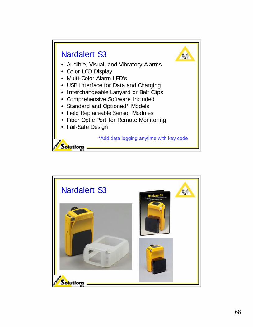
Nardalert S3• Audible, Visual, and Vibratory Alarms• Color LCD Display• Multi-Color Alarm LED’s • USB Interface for Data and Charging• Interchangeable Lanyard or Belt Clips• Comprehensive Software Included• Standard and Optioned* Models• Field Replaceable Sensor Modules• Fiber Optic Port for Remote Monitoring• Fail-Safe Design
*Add data logging anytime with key code
Nardalert S3

69
FieldSense ProHD Monitor
• The FieldSense ProHD monitor is the successor to the SafeOne sold by the LBA group.
• Independent tests by one of the two top labs in the world, the British National Lab, indicate:
•The unit is extremely polarization sensitive, i.e. if you rotate it 90 degrees the sensitivity changes by as much as a factor of 10:1.•In some parts of the RF band the monitor is extremely oversensitive leading to alarm indications at only 2 percent of the standard.•At other parts of the RF band—especially in the critical FM/VHF TV band—the monitor did not alarm when the field level was 500 times the standard.
Monitor Comparison• The Nardalert XT was by far the most
accurate and has a number of unique features. Assume similar performance for newNardalert S3.
• The RadMan is oversensitive and sometimes responds to static but it does protect you.
• If you are on a shared site, ignore what anybody reports that their SafeOne or Field Sense is indicating. These monitors are virtually non-responsive to the most dangerous antennas—FM Radio and Television—it is not recommended.

70
Monitor Comparison• The Nardalert XT is by far the most
accurate and has a number of unique features. Assume similar performance for newNardalert S3.
• The RadMan is oversensitive and sometimes responds to static but it does protect you.
• If you are on a shared site, ignore what anybody reports that their SafeOne is indicating. Because this monitor is virtually non-responsive to the most dangerous antennas—FM Radio and Television—it is not recommended.
Shaped Frequency Response
• Monitor automatically weights and sums all signals and gives the total in percent of occupational MPE limit.
• Its sensitivity tries to follow a standard using techniques similar to filter design by using RC circuits.
• Each monitor design follows a particular standard or regulation. A monitor designed for the FCC standard has a different frequency response than one designed for the Canadian (Safety Code 6) standard.

71
Shaped Frequency Response
0.01
MHz1 3 10 30 100 300 1 3 10 30 100 3003 10 30 100 300
kHz GHz
0.11.010
100
104105
106
900/f2
f/300
mW/cm2
103
FCC MPE limit for Occupational/Controlled exposure
Frequency Response/sensitivity of Nardalert XT
Shaped Response & Multiple Sources
• If you are exposed to the energy from two antennas at different bands, the exposure is automatically evaluated.
• For example, if the total energy from an AM station with a top-mounted FM antenna is 5 mW/cm², the exposure concerns vary depending on the distribution of energy from the two antennas.

72
Multiple Source Example
• Assume the total RF field level is 5 mW/cm² and distributed in two extreme examples:
1. 4.9 mW/cm² from the AM antenna and 0.1 mW/cm² from the FM antenna.
2. Reverse the distribution.
• Your total exposure in the two examples are (in percent of the occupational MPE limit):
1. 14.9% (4.9/100 + 0.1/1.0)2. 490% (0.1/100 + 4.9/1.0)
A Nardalert XT monitor would either have the 10% indicator flashing or would “peg” with all 5 lights and the full-scale sound used for field levels of >200%.
RF Protective Suits• Stainless wire (10-25%) blended with
Nomex.
• Provides >10 dB of protection at most frequencies (concerns at AM band).
• Protection is only about 3:1 w/o hood.
• Hood is required above 800 MHz under all conditions.
• Conductive socks must be worn and in conductive contact with suit for energy to “drain” off the body.

73
RF Safety Signs
Three Basic Field Level Signs
All three signs start with “Beyond this point…”

74
RF Safety Signs—The Basics
• Do NOT over sign!
• Install signs so it is clear by what is meant by “Beyond this point”
• Use special “Tower CAUTION” signs for just about any tower site except for AM towers.
• Use special burn hazard signs for all AM towers.
NOTICE Sign
• States that “Beyond this point” fields may exceed the public MPE limit.
• Most sites, other than AM, can use this sign at the gate as sort of a pre-warning even if the field levels on the ground are below the public limit.

75
CAUTION Sign
• States that “Beyond this point” fields may exceed the human MPE limit. (human = occupational/controlled MPE limit)
• Sites where some areas on the ground exceed the occupational limit should use this sign. Few sites need this sign.
WARNING Sign
• States that “Beyond this point” fields exceed the human (occupational) MPE limit.
• If you have this sign, it means nobody should enter the area unless power is reduced.
• It is extremely rare to need or want to use this sign but it is not uncommon to see it.

76
Tower CAUTION
• States that “on the tower, near some of the antennas that fields may exceed the human limit. ”
• This is the ideal sign for virtually every tower site, other than AM towers.
DANGER Burns Sign
• All AM sites should have both field level and burn signs.
• Burns are a hot button with FCC inspectors.
• Note that the action word is DANGER, which is a higher threat than WARNING.

77
Guy Wires Sign
• Rarely needed but if you don’t have an insulator near the bottom of your guy wires as well as one at the top, you may have an issue.
Signs for the Totally Confused

78
Signs for the Totally Confused
RF Radiation Safety
Common Sense and Following Procedures Help Keep You Safe