rf test report - images-na.ssl-images-amazon.comreport no.: agc08074160901ee13 page 5 of 80 2. eut...
TRANSCRIPT
Page 1 of 80
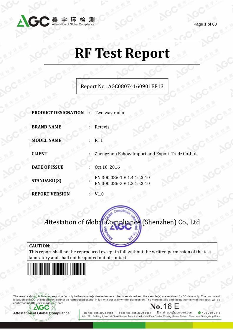
RF Test Report
PRODUCT DESIGNATION : Two way radio
BRAND NAME : Retevis
MODEL NAME : RT1
CLIENT : Zhengzhou Eshow Import and Export Trade Co.,Ltd.
DATE OF ISSUE : Oct.10, 2016
STANDARD(S) : EN 300 086-1 V 1.4.1: 2010 EN 300 086-2 V 1.3.1: 2010
REPORT VERSION : V1.0
Attestation of Global Compliance (Shenzhen) Co., Ltd
CAUTION: This report shall not be reproduced except in full without the written permission of the test laboratory and shall not be quoted out of context.
Report No.: AGC08074160901EE13

Report No.: AGC08074160901EE13 Page 2 of 80
REPORT REVISE RECORD
Report Version Revise Time Issued Date Valid Version Notes
V1.0 / Oct.10, 2016 Valid Re-certification Report
Note: The model is identical to the basic model in the report AGC01039140901EE13, except for the model name,
brand, the applicant and manufacture.
So the below test result same as the basic model in the report AGC01039140901EE13, for more
information, please refer to the original report.

Report No.: AGC08074160901EE13 Page 3 of 80
TABLE OF CONTENTS
1. TEST RESULT CERTIFICATION .............................................................................................................. 4
2. EUT DESCRIPTION .................................................................................................................................. 5
3. TEST METHODOLOGY ............................................................................................................................ 6
3.1 GENERAL DESCRIPTION OF APPLIED STANDARDS ...................................................................... 6
3.2 DESCRIPTION OF TEST MODES ....................................................................................................... 6
4. FACILITIES AND ACCREDITATIONS ...................................................................................................... 7
4.1 FACILITIES .......................................................................................................................................... 7
4.2 EQUIPMENT ....................................................................................................................................... 7
5. SETUP OF EQUIPMENT UNDER TEST .................................................................................................. 8
5.1 SETUP CONFIGURATION OF EUT .................................................................................................... 8
5.2 SUPPORT EQUIPMENT ..................................................................................................................... 8
6. ETSI EN 300 086-1/-2 REQUIREMENTS FOR TRANSMITTER .............................................................. 9
6.1 FREQUENCY ERROR ........................................................................................................................ 9
6.2 TRANSMITTER POWER (CONDUCTED) ......................................................................................... 14
6.3 MAXIMUM EFFECTIVE RADIATED POWER (NOT APPLICABLE TO DEVICE WITH EXTERNAL RF
PORT) ..................................................................................................................................................... 19
6.4 FREQUENCY DEVIATION ................................................................................................................ 20
6.5 ADJACENT AND ALTERNATE CHANNEL POWER .......................................................................... 24
6.6 UNWANTED EMISSIONS IN THE SPURIOUS DOMAIN .................................................................. 29
6.7 INTERMODULATION ATTENUATION ............................................................................................... 37
7. ETSI EN 300 086-1/2 REQUIREMENTS FOR RECEIVER ..................................................................... 38
7.1 MAXIMUM USABLE SENSITIVITY (CONDUCTED) .......................................................................... 38
7.2 AVERAGE USABLE SENSITIVITY (FIELD STRENGTH) (NOT APPLICABLE TO DEVICE WITH
EXTERNAL RF PORT) ............................................................................................................................ 43
7.3 CO-CHANNEL REJECTION .............................................................................................................. 44
7.4 ADJACENT CHANNEL SELECTIVITY .............................................................................................. 47
7.5 SPURIOUS RESPONSE REJECTION .............................................................................................. 58
7.6 INTER MODULATION RESPONSE REJECTION .............................................................................. 59
7.7 BLOCKING OR DESENSITIZATION ................................................................................................. 62
7.8 SPURIOUS RADIATIONS ................................................................................................................. 65
8. DUPLEX OPERATION (NOT APPLICABLE) ......................................................................................... 72
8.1 RECEIVER DESENSITIZATION (WITH SIMULTANEOUS TRANSMISSION AND RECEPTION) ..... 72
8.2 RECEIVER SPURIOUS RESPONSE REJECTION (WITH SIMULTANEOUS TRANSMISSION AND
RECEPTION) .......................................................................................................................................... 73
APPENDIX 1:HOTOGRAPHS OF TEST SETUP ....................................................................................... 74
APPENDIX 2:HOTOGRAPHS OF EUT ...................................................................................................... 75

Report No.: AGC08074160901EE13 Page 4 of 80
1. TEST RESULT CERTIFICATION
Applicant Zhengzhou Eshow Import and Export Trade Co.,Ltd.
Address Room 722, Sanjiang Building, No.170, Nanyang Road, Huiji District, Zhengzhou City, Henan, China
Manufacturer Shenzhen Retevis Technology Co.,Ltd
Address Room 700, 7/F., 13-C, Zhonghaixin Science & Technology Park, No.12 Ganli 6th Road, Buji Street, Longgang District, Shenzhen, China
Product Designation Two way radio
Brand Name Retevis
Model Name RT1
Date of Test Sep.29, 2016 to Oct.09, 2016
Test Result Pass
The above equipment was tested by Attestation of Global Compliance (Shenzhen) Co., Ltd. for compliance
with the requirements set forth in the European Standard ETSI EN 300 086-1 and ETSI EN 300 086-2. The
results of testing in this report apply to the product /system which was tested only. Other similar equipment
will not necessarily produce the same results due to production tolerance and measurement uncertainties.
Tested by
Steven Zhou(Zhou Pengyun) Oct.10, 2016
Reviewed by
Stone Zhou(Zhou Dong) Oct.10, 2016
Approved by
Solger Zhang(Zhang Hongyi)
Authorized Officer Oct.10, 2016

Report No.: AGC08074160901EE13 Page 5 of 80
2. EUT DESCRIPTION
Product Designation Two way radio
Brand Name Retevis
Model Name RT1
Hardware Version N/A
Software Version N/A
Operation Frequency 400-470MHz
Modulation FM
Antenna Gain 1.5dBi
Operation Mode Push to talk
Channel Separation 12.5 KHz, 25 KHz
Rated Output Power 4W (It was fixed by the manufacturer, any individual can’t arbitrarily change it.)
Antenna Designation Detachable
Power Supply DC 7.4V, 3600mAh (by battery)
Test Frequencies
400.025MHz, 430.025MHz, 435.025MHz, 440.025MHz, 469.975MHz
430.025MHz and 440.025MHz for Limit testing.
(Near lowest, near middle & near highest frequencies in the frequency range of operation.)
Note: For more details, please refer to the user’s manual of the EUT.
Report No.: AGC08074160901EE13 Page 6 of 80
3. TEST METHODOLOGY
3.1 GENERAL DESCRIPTION OF APPLIED STANDARDS
According to its specifications, the EUT must comply with the requirements of the following standards:
ETSI EN 300 086-1 – Electromagnetic compatibility and Radio spectrum Matters (ERM); Land Mobile Service; Radio equipment with an internal or external RF connector intended primarily for analogue speech;
Part 1: Technical characteristics and methods of measurement.
ETSI EN 300 086-2 – Electromagnetic compatibility and Radio spectrum Matters (ERM); Land Mobile Service; Radio equipment with an internal or external RF Connector intended primarily for analogue speech; Part 2: Harmonized EN covering essential requirements under article 3.2 of the R&TTE Directive.
3.2 DESCRIPTION OF TEST MODES
The EUT has been tested under typical operating condition. No software used to control the EUT for staying in transmitting and receiving mode for testing.

Report No.: AGC08074160901EE13 Page 7 of 80
4. FACILITIES AND ACCREDITATIONS
4.1 FACILITIES
4.2 EQUIPMENT
Radiated emissions are measured with one or more of the following types of linearly polarized antennas: tuned dipole, biconical, log periodic, bi-log, and/or ridged waveguide, horn. Spectrum analyzers with preselectors and quasi-peak detectors are used to perform radiated measurements.
Conducted emissions are measured with Line Impedance Stabilization Networks and EMI Test Receivers.
Calibrated wideband preamplifiers, coaxial cables, and coaxial attenuators are also used for making measurements.
All receiving equipment conforms to CISPR Publication 16-1, “Radio Interference Measuring Apparatus and Measurement Methods.
Site Attestation of Global Compliance (Shenzhen) Co., Ltd
Location 1 B112-B113, Building 12, Baoan Building Materials Center, No.1 of Xixiang Inner Ring Road, Baoan District, Shenzhen, Guangdong, P.R.China

Report No.: AGC08074160901EE13 Page 8 of 80
5. SETUP OF EQUIPMENT UNDER TEST
5.1 SETUP CONFIGURATION OF EUT
See test photographs attached in Appendix 1 for the actual connections between EUT and support equipment.
5.2 SUPPORT EQUIPMENT
No. Device Type Brand Model Series No. Data Cable Power Cord
1 -- -- -- -- -- --
Notes:
1. All the equipment/cables were placed in the worst-case configuration to maximize the emission during the test.
2. Grounding was established in accordance with the manufacturer’s requirements and conditions for the intended use.

Report No.: AGC08074160901EE13 Page 9 of 80
6. ETSI EN 300 086-1/-2 REQUIREMENTS FOR TRANSMITTER
6.1 FREQUENCY ERROR
LIMIT
ETSI EN 300 086-1 (V.1.4.1) Sub-clause 7.1.3
The frequency error, as defined in EN 300 086-1 sub-clause 7.1.1, shall not exceed the limits in EN 300 086-1 sub-clause 7.1.3, table 1.
MEASUREMENT EQUIPMENT USED
Name of Equipment Manufacturer Model Serial
Number Calibration
Date Calibration
Due
SPECTRUM ANALYZER AGILENT N9010A MY53470504 2015.11.09 2016.11.08
Power Attenuator WEINSCHEL
CORP 58-30-33 ML030 2016.07.02 2017.07.01
H & T CHAMBER EXPERY TN-400 TN2007SR038 2016.07.02 2017.07.01
Remark: Each piece of equipment is scheduled for calibration once a year. TEST CONFIGURATION
Attenuator
Variable DC Power Supply
SPA EUT
Temperature Chamber

Report No.: AGC08074160901EE13 Page 10 of 80
TEST PROCEDURE
1. Please refer to ETSI EN 300 086-1 (V.1.4.1) Sub-clause 5.3 and Sub-clause 5.4 for the test conditions. 2. Please refer to ETSI EN 300 086-1 (V 1.4.1) Sub-clause 7.1.2 for the measurement method. TEST RESULTS
The Bottom Channel of 25 KHz Channel Separation
Frequency Measured Frequency Error
Temperature ( ℃ ) Voltage ( V ) (MHz) ( KHz )
T Nor ( 25℃ ) DC 7.40V 400.025229 0.229
DC 6.29V 400.025364 0.363
DC 7.40V 400.025456 0.459
DC 6.29V 400.025372 0.377
DC 7.40V 400.025537 0.534
Result Pass
Test Condition
T min ( -20℃ )
T Max ( 55℃ )
Limit ±2 KHz @ 400.025MHz
The Middle Channel (430.025MHz) of 25 KHz Channel Separation
Frequency Measured Frequency Error
Temperature ( ℃ ) Voltage ( V ) (MHz) ( KHz )
T Nor ( 25℃ ) DC 7.40V 430.025262 0.262
DC 6.29V 430.025375 0.375
DC 7.40V 430.025487 0.487
DC 6.29V 430.025343 0.343
DC 7.40V 430.025468 0.468
Result Pass
Test Condition
T min ( -20℃ )
T Max ( 55℃ )
Limit ±2KHz @ 430.025MHz
The Middle Channel (435.025MHz) of 25 KHz Channel Separation
Frequency Measured Frequency Error
Temperature ( ℃ ) Voltage ( V ) (MHz) ( KHz )
T Nor ( 25℃ ) DC 7.40V 435.025245 0.245
DC 6.29V 435.025372 0.372
DC 7.40V 435.025534 0.534
DC 6.29V 435.025353 0.353
DC 7.40V 435.025522 0.522
Result Pass
Test Condition
T min ( -20℃ )
T Max ( 55℃ )
Limit ±2KHz @ 435.025MHz

Report No.: AGC08074160901EE13 Page 11 of 80
The Middle Channel (440.025MHz) of 25 KHz Channel Separation
Frequency Measured Frequency Error
Temperature ( ℃ ) Voltage ( V ) (MHz) ( KHz )
T Nor ( 25℃ ) DC 7.40V 440.025269 0.269
DC 6.29V 440.025388 0.388
DC 7.40V 440.025451 0.451
DC 6.29V 440.025426 0.426
DC 7.40V 440.025504 0.504
Result Pass
Test Condition
T min ( -20℃ )
T Max ( 55℃ )
Limit ±2KHz @ 440.025MHz
The Top Channel of 25 KHz Channel Separation
Frequency Measured Frequency Error
Temperature ( ℃ ) Voltage ( V ) (MHz) ( KHz )
T Nor ( 25℃ ) DC 7.40V 469.975242 0.242
DC 6.29V 469.975386 0.386
DC 7.40V 469.975477 0.477
DC 6.29V 469.975364 0.364
DC 7.40V 469.975535 0.535
Result Pass
Test Condition
T min ( -20℃ )
T Max ( 55℃ )
Limit ±2 KHz @ 469.975MHz

Report No.: AGC08074160901EE13 Page 12 of 80
The Bottom Channel of 12.5 KHz Channel Separation
Frequency Measured Frequency Error
Temperature ( ℃ ) Voltage ( V ) (MHz) ( KHz )
T Nor ( 25℃ ) DC 7.40V 400.025249 0.249
DC 6.29V 400.025368 0.368
DC 7.40V 400.025485 0.485
DC 6.29V 400.025392 0.392
DC 7.40V 400.025517 0.517
Result Pass
Test Condition
T min ( -20℃ )
T Max ( 55℃ )
Extreme temperature: ±2.50 KHz @ 400.025 MHzLimit
Normal temperature: ±1.50 KHz @ 400.025
MHz
The Middle Channel (430.025MHz) of 12.5 KHz Channel Separation
Frequency Measured Frequency Error
Temperature ( ℃ ) Voltage ( V ) (MHz) ( KHz )
T Nor ( 25℃ ) DC 7.40V 430.025256 0.256
DC 6.29V 430.025338 0.338
DC 7.40V 430.025432 0.432
DC 6.29V 430.025387 0.387
DC 7.40V 430.025471 0.471
Result Pass
Test Condition
T min ( -20℃ )
T Max ( 55℃ )
Extreme temperature: ±2.50 KHz @ 430.025 MHzLimit
Normal temperature: ±1.50 KHz @ 430.025
MHz
The Middle Channel (435.025MHz) of 12.5 KHz Channel Separation
Frequency Measured Frequency Error
Temperature ( ℃ ) Voltage ( V ) (MHz) ( KHz )
T Nor ( 25℃ ) DC 7.40V 435.025279 0.279
DC 6.29V 435.025334 0.334
DC 7.40V 435.025436 0.436
DC 6.29V 435.025365 0.365
DC 7.40V 435.025493 0.493
Result Pass
Test Condition
T min ( -20℃ )
T Max ( 55℃ )
Extreme temperature: ±2.50 KHz @ 435.025 MHzLimit
Normal temperature: ±1.50 KHz @ 435.025
MHz

Report No.: AGC08074160901EE13 Page 13 of 80
The Middle Channel (440.025MHz) of 12.5 KHz Channel Separation
Frequency Measured Frequency Error
Temperature ( ℃ ) Voltage ( V ) (MHz) ( KHz )
T Nor ( 25℃ ) DC 7.40V 440.025279 0.279
DC 6.29V 440.025386 0.386
DC 7.40V 440.025438 0.438
DC 6.29V 440.025467 0.467
DC 7.40V 440.025583 0.583
Result Pass
Test Condition
T min ( -20℃ )
T Max ( 55℃ )
Extreme temperature: ±2.50 KHz @ 400.025 MHzLimit
Normal temperature: ±1.50 KHz @ 400.025
MHz
The Top Channel of 12.5 KHz Channel Separation
Frequency Measured Frequency Error
Temperature ( ℃ ) Voltage ( V ) (MHz) ( KHz )
T Nor ( 25℃ ) DC 7.40V 469.975279 0.279
DC 6.29V 469.975362 0.362
DC 7.40V 469.975458 0.458
DC 6.29V 469.975477 0.477
DC 7.40V 469.975523 0.523
Result Pass
Test Condition
T min ( -20℃ )
T Max ( 55℃ )
Extreme temperature: ±2.50 KHz @ 469.975 MHzLimit
Normal temperature: ±1.50 KHz @ 469.975
MHz

Report No.: AGC08074160901EE13 Page 14 of 80
6.2 TRANSMITTER POWER (CONDUCTED)
LIMIT
ETSI EN 300 086-1 (V.1.4.1) Sub-clause 7.2.3
The transmitter power (conducted) as defined in ETSI EN 300 086-1 Sub-clause 7.2.1 under the specified conditions of measurement and at normal test conditions shall be within ± 1.5 dB of the rated output power. Furthermore, the carrier power (conducted) shall not exceed the maximum value allowed by the Administrations. The transmitter power (conducted) under extreme test conditions shall be within +2.0dB and -3.0dB of the rated output power. MEASUREMENT EQUIPMENT USED
Name of Equipment Manufacturer Model Serial
Number Calibration
Date Calibration
Due
SPECTRUM ANALYZER AGILENT N9010A MY53470504 2015.11.09 2016.11.08
Power Attenuator WEINSCHEL
CORP 58-30-33 ML030 2016.07.02 2017.07.01
H & T CHAMBER EXPERY TN-400 TN2007SR038 2016.07.02 2017.07.01
Remark: Each piece of equipment is scheduled for calibration once a year. TEST CONFIGURATION
TEST PROCEDURE 1. Please refer to ETSI EN 300 086-1 (V.1.4.1) Sub-clause 5.3 and 6.4 for the test conditions. 2. Please refer to ETSI EN 300 086-1 (V1.4.1) Sub-clause 7.2.2 for the measurement method. TEST RESULTS
Attenuator
Variable DC Power Supply
SPA
EUT
Temperature Chamber

Report No.: AGC08074160901EE13 Page 15 of 80
The Bottom Channel of 25 KHz Channel Separation-4W
Power Measured Power Error
Temperature ( ℃ ) Voltage ( V ) ( dBm ) ( dB )
T Nor ( 25℃ ) DC 7.40V 35.88 -0.14
DC 6.29V 35.83 -0.19
DC 7.40V 35.86 -0.16
DC 6.29V 35.92 -0.10
DC 7.40V 35.85 -0.17
Result Pass
Test Condition
T min ( -20℃ )
T Max ( 55℃ )
Nominal Power= 36.02dBm; Limit n=±1.5 dB and Limit e=2 dB & -3 dB
The Middle Channel (430.025MHz) of 25 KHz Channel Separation-4W
Power Measured Power Error
Temperature ( ℃ ) Voltage ( V ) ( dBm ) ( dB )
T Nor ( 25℃ ) DC 7.40V 35.85 -0.17
DC 6.29V 35.91 -0.11
DC 7.40V 35.88 -0.14
DC 6.29V 35.83 -0.19
DC 7.40V 35.84 -0.18
Result Pass
Test Condition
T min ( -20℃ )
T Max ( 55℃ )
Nominal Power= 36.02dBm; Limit n=±1.5 dB and Limit e=2 dB & -3 dB
The Middle Channel (435.025MHz) of 25 KHz Channel Separation-4W
Power Measured Power Error
Temperature ( ℃ ) Voltage ( V ) ( dBm ) ( dB )
T Nor ( 25℃ ) DC 7.40V 35.89 -0.13
DC 6.29V 35.86 -0.16
DC 7.40V 35.92 -0.10
DC 6.29V 35.87 -0.15
DC 7.40V 35.88 -0.14
Result Pass
Test Condition
T min ( -20℃ )
T Max ( 55℃ )
Nominal Power= 36.02dBm; Limit n=±1.5 dB and Limit e=2 dB & -3 dB

Report No.: AGC08074160901EE13 Page 16 of 80
The Middle Channel (440.025MHz) of 25 KHz Channel Separation-4W
Power Measured Power Error
Temperature ( ℃ ) Voltage ( V ) ( dBm ) ( dB )
T Nor ( 25℃ ) DC 7.40V 35.87 -0.15
DC 6.29V 35.86 -0.16
DC 7.40V 35.84 -0.18
DC 6.29V 35.90 -0.12
DC 7.40V 35.91 -0.11
Result Pass
Test Condition
T min ( -20℃ )
T Max ( 55℃ )
Nominal Power= 36.02 dBm; Limit n=±1.5 dB and Limit e=2 dB & -3 dB
The Top Channel of 25 KHz Channel Separation-4W
Power Measured Power Error
Temperature ( ℃ ) Voltage ( V ) ( dBm ) ( dB )
T Nor ( 25℃ ) DC 7.40V 35.89 -0.09
DC 6.29V 35.86 -0.12
DC 7.40V 35.83 -0.15
DC 6.29V 35.87 -0.11
DC 7.40V 35.84 -0.14
Result Pass
Test Condition
T min ( -20℃ )
T Max ( 55℃ )
Nominal Power= 35.98 dBm; Limit n=±1.5 dB and Limit e=2 dB & -3 dB
Report No.: AGC08074160901EE13 Page 17 of 80
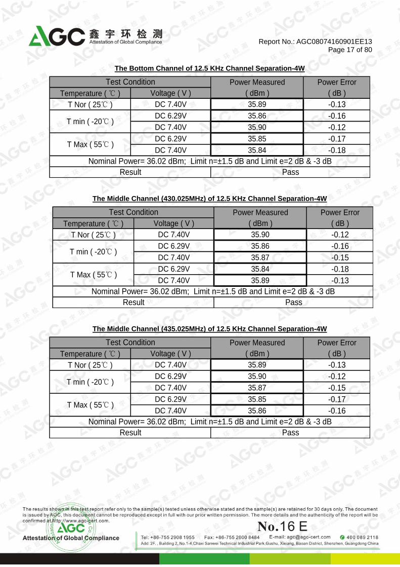
The Bottom Channel of 12.5 KHz Channel Separation-4W
Power Measured Power Error
Temperature ( ℃ ) Voltage ( V ) ( dBm ) ( dB )
T Nor ( 25℃ ) DC 7.40V 35.89 -0.13
DC 6.29V 35.86 -0.16
DC 7.40V 35.90 -0.12
DC 6.29V 35.85 -0.17
DC 7.40V 35.84 -0.18
Result Pass
Test Condition
T min ( -20℃ )
T Max ( 55℃ )
Nominal Power= 36.02 dBm; Limit n=±1.5 dB and Limit e=2 dB & -3 dB
The Middle Channel (430.025MHz) of 12.5 KHz Channel Separation-4W
Power Measured Power Error
Temperature ( ℃ ) Voltage ( V ) ( dBm ) ( dB )
T Nor ( 25℃ ) DC 7.40V 35.90 -0.12
DC 6.29V 35.86 -0.16
DC 7.40V 35.87 -0.15
DC 6.29V 35.84 -0.18
DC 7.40V 35.89 -0.13
Result Pass
Test Condition
T min ( -20℃ )
T Max ( 55℃ )
Nominal Power= 36.02 dBm; Limit n=±1.5 dB and Limit e=2 dB & -3 dB
The Middle Channel (435.025MHz) of 12.5 KHz Channel Separation-4W
Power Measured Power Error
Temperature ( ℃ ) Voltage ( V ) ( dBm ) ( dB )
T Nor ( 25℃ ) DC 7.40V 35.89 -0.13
DC 6.29V 35.90 -0.12
DC 7.40V 35.87 -0.15
DC 6.29V 35.85 -0.17
DC 7.40V 35.86 -0.16
Result Pass
Test Condition
T min ( -20℃ )
T Max ( 55℃ )
Nominal Power= 36.02 dBm; Limit n=±1.5 dB and Limit e=2 dB & -3 dB

Report No.: AGC08074160901EE13 Page 18 of 80
The Middle Channel (440.025MHz) of 12.5 KHz Channel Separation-4W
Power Measured Power Error
Temperature ( ℃ ) Voltage ( V ) ( dBm ) ( dB )
T Nor ( 25℃ ) DC 7.40V 35.89 -0.13
DC 6.29V 35.85 -0.17
DC 7.40V 35.86 -0.16
DC 6.29V 35.82 -0.20
DC 7.40V 35.88 -0.14
Result Pass
Test Condition
T min ( -20℃ )
T Max ( 55℃ )
Nominal Power= 36.02 dBm; Limit n=±1.5 dB and Limit e=2 dB & -3 dB
The Top Channel of 12.5 KHz Channel Separation-4W
Power Measured Power Error
Temperature ( ℃ ) Voltage ( V ) ( dBm ) ( dB )
T Nor ( 25℃ ) DC 7.40V 35.91 -0.11
DC 6.29V 35.84 -0.18
DC 7.40V 35.80 -0.22
DC 6.29V 35.87 -0.15
DC 7.40V 35.79 -0.23
Result Pass
Test Condition
T min ( -20℃ )
T Max ( 55℃ )
Nominal Power= 36.02 dBm; Limit n=±1.5 dB and Limit e=2 dB & -3 dB

Report No.: AGC08074160901EE13 Page 19 of 80
6.3 MAXIMUM EFFECTIVE RADIATED POWER (NOT APPLICABLE TO DEVICE WITH EXTERNAL RF
PORT)
LIMIT
N/A
MEASUREMENT EQUIPMENT USED
N/A
TEST PROCEDURE
N/A
TEST CONFIGURATION
N/A
TEST RESULTS N/A

Report No.: AGC08074160901EE13 Page 20 of 80
6.4 FREQUENCY DEVIATION
LIMIT
ETSI EN 300 086-1 (V.1.4.1) Sub-clause 7.4.3 The maximum permissible frequency deviation as defined in Sub-clause 7.4.1 for modulation frequencies from the lowest frequency transmitted (f1) by the equipment (as declared by the manufacturer) up to (f2) shall be as given in table 2.
Table 2
Channel separation ( KHz )
Maximum permissible frequency deviation (kHz)
12.5 kHz ±2.5 kHz
20 kHz ±4 kHz
25 kHz ±5 kHz
ETSI EN 300 086-1 (V.1.4.1) Sub-clause 7.4.3.2 The frequency deviation at modulation frequencies between 3.0 KHz (for equipment operating with 20 KHz or 25 KHz channel separations) and 2.55 KHz (for equipment operating with 12.5 KHz channel separation) and 6.0 KHz shall not exceed the frequency deviation at a modulation frequency of 3.0 KHz/2.55 KHz. At 6.0 KHz the deviation shall be not more than 30% of the maximum permissible frequency deviation. The frequency deviation at modulation frequencies between 6.0 KHz and a frequency equal to the channel separation for which the equipment is intended shall not exceed that given by a linear representation of the frequency deviation (dB) relative to the modulation frequency, starting at the 6.0 KHz limit and having a slope of -14.0 dB per octave. These limits are illustrated in figure below.

Report No.: AGC08074160901EE13 Page 21 of 80
MEASUREMENT EQUIPMENT USED
Name of Equipment Manufacturer Model Serial Number Calibration Due
SIGNAL GENERATOR Aglient E4421B MY43351603 2017.07.01
POWER ATTENUATOR WEINSCHEL CORP
58-30-33 ML030 2017.07.01
SPECTRUM ANALYZER AGILENT N9010A MY53470504 2016.10.08
TEST CONFIGURATION
TEST PROCEDURE
1. Please refer to ETSI EN 300 086-1 (V.1.4.1) Sub-clause 5.3 for the test conditions. 2. Please refer to ETSI EN 300 086-1 (V1.4.1) Sub-clause 7.4.2 for the measurement method.
EUT
Signal Generator
Attenuator
SPA

Report No.: AGC08074160901EE13 Page 22 of 80
TEST RESULTS
The Middle Channel @ 25.0 KHz Channel Separation (Worst Case)
Audio Frequency (KHz)
Test Value (KHz)
Limit (KHz)
Audio Frequency (KHz)
Test Value (KHz)
Limit (KHz)
0.10 0.12 5.00 5.50 2.09 3.89
0.20 0.24 5.00 6.00 1.76 3.89
0.30 0.50 5.00 6.00 1.44 1.50
0.40 0.65 5.00 6.50 1.08 1.25
0.50 0.72 5.00 7.00 0.96 1.05
0.60 1.21 5.00 7.50 0.81 0.89
0.70 1.32 5.00 8.00 0.66 0.77
0.80 2.45 5.00 8.50 0.42 0.67
0.90 2.52 5.00 9.00 0.31 0.58
1.00 3.05 5.00 9.50 0.23 0.52
1.20 3.48 5.00 10.00 0.17 0.46
1.40 3.63 5.00 10.50 0.16 0.41
1.60 4.12 5.00 11.00 0.09 0.37
1.80 4.33 5.00 11.50 0.07 0.33
2.00 4.45 5.00 12.00 0.05 0.30
2.20 4.51 5.00 12.50 0.04 0.27
2.40 4.64 5.00 13.00 0.03 0.25
2.55 4.77 5.00 14.00 0.01 0.23
2.60 4.45 5.00 15.00 -- 0.18
2.80 4.37 5.00 16.00 -- 0.15
3.00 3.89 5.00 17.00 -- 0.13
Limit(3K-6K)=Value measured at 3K 18.00 -- 0.12
3.20 3.62 3.89 19.00 -- 0.10
3.40 3.74 3.89 20.00 -- 0.09
3.60 3.61 3.89 21.00 -- 0.08
3.80 3.54 3.89 22.00 -- 0.07
4.00 3.39 3.89 23.00 -- 0.07
4.50 2.47 3.89 24.00 -- 0.06
5.00 2.12 3.89 25.00 -- 0.05

Report No.: AGC08074160901EE13 Page 23 of 80
The Middle Channel @ 12.5 KHz Channel Separation (Worst Case)
Audio Frequency (KHz)
Test Value (KHz)
Limit (KHz)
Audio Frequency (KHz)
Test Value (KHz)
Limit (KHz)
0.10 0.09 2.50 5.50 1.14 1.95
0.20 0.26 2.50 6.00 1.03 1.95
0.30 0.35 2.50 6.00 0.64 0.75
0.40 0.46 2.50 6.50 0.45 0.62
0.50 0.63 2.50 7.00 0.33 0.52
0.60 0.81 2.50 7.50 0.25 0.45
0.70 1.29 2.50 8.00 0.16 0.38
0.80 1.31 2.50 8.50 0.11 0.33
0.90 1.46 2.50 9.00 0.09 0.29
1.00 1.53 2.50 9.50 0.08 0.26
1.20 1.65 2.50 10.00 0.07 0.23
1.40 1.84 2.50 10.50 0.06 0.20
1.60 1.96 2.50 11.00 0.04 0.18
1.80 2.18 2.50 11.50 0.03 0.17
2.00 2.23 2.50 12.00 0.02 0.15
2.20 2.36 2.50 12.50 0.01 0.14
2.40 2.15 2.50
2.55 1.95 2.50
Limit(2.6K-6K)=Value measured at 2.55K
2.60 1.85 1.95
2.80 1.81 1.95
3.00 1.78 1.95
3.20 1.73 1.95
3.40 1.64 1.95
3.60 1.61 1.95
3.80 1.53 1.95
4.00 1.42 1.95
4.50 1.33 1.95
5.00 1.24 1.95

Report No.: AGC08074160901EE13 Page 24 of 80
6.5 ADJACENT AND ALTERNATE CHANNEL POWER
LIMIT
ETSI EN 300 086-1 (V.1.4.1) Sub-clause 7.5.3 The adjacent and alternate channel power as defined in ETSI EN 300 086-1 Sub-clause 7.5.1, for channel separations of 12.5 KHz, 20 KHz and 25 KHz, the adjacent channel power shall not exceed a value of 60.0 dB below the transmitter power of the transmitter without the need to be below 0.2 uW. For channel separations of 12.5 KHz, 20 KHz and 25 KHz, the alternate channel power shall not exceed a value of 70.0 dB below the transmitter power of the transmitter without the need to be below 0.2 uW. MEASUREMENT EQUIPMENT USED
Name of Equipment Manufacturer Model Serial Number Calibration
Date Calibration Due
SPECTRUM ANALYZER AGILENT N9010A MY53470504 2015.11.09 2016.11.08
POWER ATTENUATOR WEINSCHEL CORP
58-30-33 ML030 2016.07.02 2017.07.01
SIGNAL GENERATOR Aglient E4421B MY43351603 2016.07.02 2017.07.01
TEST CONFIGURATION
TEST PROCEDURE
1. Please refer to ETSI EN 300 086-1 (V.1.4.1) Sub-clause 5.3 for the test conditions. 2. Please refer to ETSI EN 300 086-1 (V1.4.1) Sub-clause 7.5.2 for the measurement method.
EUT
Signal Generator
Attenuator
SPA

Report No.: AGC08074160901EE13 Page 25 of 80
TEST RESULTS Test Result of Adjacent Channel Power:
The Top Channel of 25 KHz Channel Separation
Test Condition
Measurement Offset
Adjacent Channel Power
( dBc ) Temperature ( ℃ ) Voltage ( V )
T Nor ( 25℃ ) V Nor (7.40V)
+17 KHz 73.6
-17 KHz 73.7
Applicable Limit 60 dBc or 0.2 uW
Result Pass
The Middle Channel (435.025MHz) of 25 KHz Channel Separation
Test Condition
Measurement Offset
Adjacent Channel Power
( dBc ) Temperature ( ℃ ) Voltage ( V )
T Nor ( 25℃ ) V Nor (7.40V)
+17 KHz 73.2
-17 KHz 73.5
Applicable Limit 60 dBc or 0.2 uW
Result Pass
The Bottom Channel of 25 KHz Channel Separation
Test Condition
Measurement Offset
Adjacent Channel Power
( dBc ) Temperature ( ℃ ) Voltage ( V )
T Nor ( 25℃ ) V Nor (7.40V)
+17 KHz 73.5
-17 KHz 73.3
Applicable Limit 60 dBc or 0.2 uW
Result Pass

Report No.: AGC08074160901EE13 Page 26 of 80
The Top Channel of 12.5 KHz Channel Separation
Test Condition
Measurement Offset
Adjacent Channel Power
( dBc ) Temperature ( ℃ ) Voltage ( V )
T Nor ( 25℃ ) V Nor (7.40V)
+8.25 KHz 73.7
-8.25 KHz 72.4
Applicable Limit 60 dBc or 0.2 uW
Result Pass
The Middle Channel (435.025MHz) of 12.5 KHz Channel Separation
Test Condition
Measurement Offset
Adjacent Channel Power
( dBc ) Temperature ( ℃ ) Voltage ( V )
T Nor ( 25℃ ) V Nor (7.40V)
+8.25 KHz 74.6
-8.25 KHz 73.3
Applicable Limit 60 dBc or 0.2 uW
Result Pass
The Bottom Channel of 12.5 KHz Channel Separation
Test Condition
Measurement Offset
Adjacent Channel Power
( dBc ) Temperature ( ℃ ) Voltage ( V )
T Nor ( 25℃ ) V Nor (7.40V)
+8.25 KHz 74.8
-8.25 KHz 73.7
Applicable Limit 60 dBc or 0.2 uW
Result Pass

Report No.: AGC08074160901EE13 Page 27 of 80
Test Result of Alternate Channel Power:
The Top Channel of 25 KHz Channel Separation
Test Condition
Measurement Offset
Alternate Channel Power
( dBc ) Temperature ( ℃ ) Voltage ( V )
T Nor ( 25℃ ) V Nor (7.40V)
+42 KHz 80.2
-42 KHz 81.3
Applicable Limit 70 dBc or 0.2 uW
Result Pass
The Middle Channel (435.025MHz) of 25 KHz Channel Separation
Test Condition
Measurement Offset
Alternate Channel Power
( dBc ) Temperature ( ℃ ) Voltage ( V )
T Nor ( 25℃ ) V Nor (7.40V)
+42 KHz 80.8
-42 KHz 81.5
Applicable Limit 70 dBc or 0.2 uW
Result Pass
The Bottom Channel of 25 KHz Channel Separation
Test Condition
Measurement Offset
Alternate Channel Power
( dBc ) Temperature ( ℃ ) Voltage ( V )
T Nor ( 25℃ ) V Nor (7.40V)
+42 KHz 81.5
-42 KHz 82.7
Applicable Limit 70 dBc or 0.2 uW
Result Pass

Report No.: AGC08074160901EE13 Page 28 of 80
The Top Channel of 12.5 KHz Channel Separation
Test Condition
Measurement Offset
Alternate Channel Power
( dBc ) Temperature ( ℃ ) Voltage ( V )
T Nor ( 25℃ ) V Nor (7.40V)
+20.25 KHz 82.7
-20.25 KHz 81.4
Applicable Limit 70 dBc or 0.2 uW
Result Pass
The Middle Channel (435.025MHz) of 12.5 KHz Channel Separation
Test Condition
Measurement Offset
Alternate Channel Power
( dBc ) Temperature ( ℃ ) Voltage ( V )
T Nor ( 25℃ ) V Nor (7.40V)
+20.25 KHz 81.2
-20.25 KHz 80.3
Applicable Limit 70 dBc or 0.2 uW
Result Pass
The Bottom Channel of 12.5 KHz Channel Separation
Test Condition
Measurement Offset
Adjacent Channel Power
( dBc ) Temperature ( ℃ ) Voltage ( V )
T Nor ( 25℃ ) V Nor (7.40V)
+20.25 KHz 81.5
-20.25 KHz 82.4
Applicable Limit 70 dBc or 0.2 uW
Result Pass

Report No.: AGC08074160901EE13 Page 29 of 80
6.6 UNWANTED EMISSIONS IN THE SPURIOUS DOMAIN
LIMIT
ETSI EN 300 086-1 (V.1.4.1) Sub-clause 7.6.4 Spurious emission as defined in ETSI EN 300 086-1 Sub-clause 7.6.1, the power of any spurious emission shall not exceed the values given in table 3 and table 4
Table 3: Conducted emissions
Frequency Range 9 KHz to 1GHz Above 1GHz to 4GHz, or above 1GHz to 12.75GHz
TX Operating 0.25μW (-36 dBm ) 1.00μW ( -30 dBm )
TX Standby 2.0nW (-57 dBm ) 20.00nW (-47.0 dBm)
Table 4: Radiated emissions
Frequency Range 30 MHz to 1GHz Above 1GHz to 4GHz or
above 1 GHz to 12.75 GHz
TX Operating 0.25μW (-36 dBm ) 1.00μW ( -30 dBm )
TX Standby 2.0nW (-57 dBm ) 20.00nW (-47.0 dBm)
MEASUREMENT EQUIPMENT USED
Radiated Emission Test Site # 4
Name of Equipment Manufacturer Model Serial
Number Calibration
Date Calibration Due
EMI TEST RECEIVER R&S ESCI 10096 2016.07.02 2017.07.01
AMPLIFIER Schwarzbeck BBV 9718 9718-162 2016.07.02 2017.07.01
SPECTRUM ANALYZER
AGILENT N9010A MY53470504 2015.11.09 2016.11.08
ATTENUATOR WEINSCHEL CORP 58-30-33 ML030 2016.07.02 2017.07.01
ANTENNA R&S VULB9168 D69250 2016.03.01 2017.02.28
Double-Ridged Waveguide Horn
ETS LINDGREN 3117 00034609 2016.03.01 2017.02.28
Remark: Each piece of equipment is scheduled for calibration once a year.

Report No.: AGC08074160901EE13 Page 30 of 80
TEST CONFIGURATION Conducted Measurement (9 KHz to 12.75GHz)
Effective Radiated Power measurement (30MHz to 12.75 GHz)
Below 1GHz
EUT
Attenuator
Receiver

Report No.: AGC08074160901EE13 Page 31 of 80
Above 1GHz
TEST PROCEDURE 1. Please refer to ETSI EN 300 086-1 (V.1.4.1) Sub-clause 5.3 for the test conditions. 2. Please refer to ETSI EN 300 086-1 (V1.4.1) Sub-clause 7.6.2 and 7.6.3 for the measurement method. TEST RESULTS Conducted Measurement (9 KHz to 12.75GHz) --- PASS
Note: only result the worst case in this part.

Report No.: AGC08074160901EE13 Page 32 of 80
UNWANTED EMISSIONS AT LOW CHANNEL (400.025MHz with 12.5 KHz channel separation)
9KHZ-150KHz
150KHz-30MHz

Report No.: AGC08074160901EE13 Page 33 of 80
30MHz-1GHz
1GHZ-12.75GHZ
Note: Above is the worst condition data.

Report No.: AGC08074160901EE13 Page 34 of 80
UNWANTED EMISSIONS AT LOW CHANNEL (400.025MHz with 25 KHz channel separation)
9KHZ-150KHz
150KHz-30MHz

Report No.: AGC08074160901EE13 Page 35 of 80
30MHz-1GHz
1GHZ-12.75GHZ
Note: Above is the worst condition data.

Report No.: AGC08074160901EE13 Page 36 of 80
Effective Radiated Power measurement (30 MHz to 12.75GHz) --- PASS
All Channels for 25 KHz Channel Separation
Frequency Reading
level Antenna S.G.
Cable loss
Ant.Gain
Emission level
Limit Margin
(MHz) (dBuV) Polarizatio
n (dBm) (dB) (dB) (dBm) (dBm) (dB)
Below 1 GHz
-- V --
At least 20 dB down
than the limit
Above 1 GHz
-- V --
Below 1 GHz
-- H --
Above 1 GHz
-- H --
Remark:
(1) Emission Level(dBm) = SG O/P-Cable + Ant Gain (2) Measuring frequencies from 30 MHz to the 4GHz.
(3) Data of measurement within this frequency range shown “--” in the table above means the reading of emissions are attenuated more than 20dB below the permissible limits or the field strength is too small to be measured.
All Channels for 12.5 KHz Channel Separation
Frequency Reading
level Antenna S.G.
Cable loss
Ant.Gain
Emission level
Limit Margin
(MHz) (dBuV) Polarizatio
n (dBm) (dB) (dB) (dBm) (dBm) (dB)
Below 1 GHz
-- V --
At least 20 dB down
than the limit
Above 1 GHz
-- V --
Below 1 GHz
-- H --
Above 1 GHz
-- H --
Remark:
(1) Emission Level(dBm) = SG O/P-Cable + Ant Gain (2) Measuring frequencies from 30 MHz to the 4GHz.
(3) Data of measurement within this frequency range shown “--” in the table above means the reading of emissions are attenuated more than 20dB below the permissible limits or the field strength is too small to be measured.

Report No.: AGC08074160901EE13 Page 37 of 80
6.7 INTERMODULATION ATTENUATION
This requirement applies only to transmitters to be used in base stations (fixed). LIMIT ETSI EN 300 086-1 (V 1.4.1) Sub-clause 7.7.3 The intermodulation attenuation as defined in ETSI EN 300 086-1 Sub-clause 7.7.1, two classes of transmitter intermodulation attenuation are defined, the equipment shall fulfill one of the requirements:
1) In general the intermodulation attenuation ratio shall be at least 40.0 dB for any intermodulation component:
2) For Handheld two way radio equipment to be used in special service conditions (e.g. at sites where more than one transmitters will be service) or where the regulatory authority makes it a conditions of the licence, the intermodulation attenuation ratio shall be at least 70.0 dB for any intermodulation component. In the case where the performance is achieved by additional internal or external isolating devices (such as circulators) these are expected be available at the time the measurement are made shall be used for the measurement.
MEASUREMENT EQUIPMENT USED
Name of Equipment
Manufacturer Model Serial Number Calibration
Date Calibration Due
Spectrum Analyser AGILENT N9010A MY53470504 2015.11.09 2016.11.08
SIGNAL GENERATOR
Aglient E4421B MY43351603 2016.07.02 2017.07.01
Directional Coupler Werlatone C5571-10 99463 2016.07.02 2017.07.01
TEST CONFIGURATION
TEST PROCEDUR
3. Please refer to ETSI EN 300 086-1 (V.1.4.1) Sub-clause 5.3 for the test conditions. 4. Please refer to ETSI EN 300 086-1 (V1.4.1) Sub-clause 7.7.2 for the measurement method. TEST RESULTS N/A

Report No.: AGC08074160901EE13 Page 38 of 80
7. ETSI EN 300 086-1/2 REQUIREMENTS FOR RECEIVER
7.1 MAXIMUM USABLE SENSITIVITY (CONDUCTED)
LIMIT
ETSI EN 300 086-1(V 1.4.1) Sub-clause 8.1.3 The maximum usable sensitivity (conducted) of the receiver as defined as in ETSI EN 300 086-1 Sub-clause 8.1.1 shall produce
a) An audio frequency output power of at least 50% of the rated power output, and b) A SND/ND ratio of 20 dB, measured at the receiver output through a telephone psophometric
weighting network as described in ITU-T Recommendation O.41[2] Red Book 1984.
The maximum usable sensitivity shall not exceed an electromotive force (emf) of+6.0 dBuV under normal test conditions, and an emf of +12.0 dBuV under extreme test conditions. MEASUREMENT EQUIPMENT USED
Name of Equipment Manufacturer Model Serial Number Calibration
Date Calibration Due
Communication Test Set
HP HP8920B US35010135 07/16/2014 07/15/2015
H&T Chamber EXPERY TN-400 TN2007SR038 07/16/2014 07/15/2015
Signal Generator R&S SMT02 A0304261 07/16/2014 07/15/2015
TEST CONFIGURATION
TEST PROCEDURE 5. Please refer to ETSI EN 300 086-1 (V.1.4.1) Sub-clause 5.3 and 5.4 for the test conditions. 6. Please refer to ETSI EN 300 086-1 (V1.4.1) Sub-clause 8.1.2 for the measurement method.
Temperature Chamber
Signal Generator
Communication Tester
EUT

Report No.: AGC08074160901EE13 Page 39 of 80
TEST RESULTS
Test Result of 25 KHz Channel Separation (400.025MHz)
Test Condition Result Measured
(dBuV)
Limit
( dBuV) Temperature ( ℃ ) Voltage ( V )
T Nor ( 25℃ ) DC 7.40V 3.52 6
T min ( -20℃ ) DC 6.29V 4.45 12
DC 7.40V 5.50 12
T Max ( 55℃ ) DC 6.29V 5.64 12
DC 7.40V 5.49 12
Result Pass
Test Result of 25 KHz Channel Separation (430.025MHz)
Test Condition Result Measured
(dBuV)
Limit
( dBuV) Temperature ( ℃ ) Voltage ( V )
T Nor ( 25℃ ) DC 7.40V 3.61 6
T min ( -20℃ ) DC 6.29V 4.22 12
DC 7.40V 5.83 12
T Max ( 55℃ ) DC 6.29V 5.34 12
DC 7.40V 5.60 12
Result Pass
Test Result of 25 KHz Channel Separation (435.025MHz)
Test Condition Result Measured
(dBuV)
Limit
( dBuV) Temperature ( ℃ ) Voltage ( V )
T Nor ( 25℃ ) DC 7.40V 3.75 6
T min ( -20℃ ) DC 6.29V 4.35 12
DC 7.40V 5.54 12
T Max ( 55℃ ) DC 6.29V 5.13 12
DC 7.40V 5.36 12
Result Pass

Report No.: AGC08074160901EE13 Page 40 of 80
Test Result of 25 KHz Channel Separation (440.025MHz)
Test Condition Result Measured
(dBuV)
Limit
( dBuV) Temperature ( ℃ ) Voltage ( V )
T Nor ( 25℃ ) DC 7.40V 3.52 6
T min ( -20℃ ) DC 6.29V 4.35 12
DC 7.40V 5.54 12
T Max ( 55℃ ) DC 6.29V 5.63 12
DC 7.40V 5.36 12
Result Pass
Test Result of 25 KHz Channel Separation (469.975MHz)
Test Condition Result Measured
(dBuV)
Limit
( dBuV) Temperature ( ℃ ) Voltage ( V )
T Nor ( 25℃ ) DC 7.40V 3.50 6
T min ( -20℃ ) DC 6.29V 4.60 12
DC 7.40V 5.51 12
T Max ( 55℃ ) DC 6.29V 5.35 12
DC 7.40V 5.47 12
Result Pass

Report No.: AGC08074160901EE13 Page 41 of 80
Test Result of 12.5 KHz Channel Separation (400.025MHz)
Test Condition Result Measured
( dBuV )
Limit
( dBuV ) Temperature ( ℃ ) Voltage ( V )
T Nor ( 25℃ ) DC 7.40V 3.86 6
T min (-20℃ ) DC 6.29V 4.35 12
DC 7.40V 4.42 12
T Max ( 55℃ ) DC 6.29V 4.31 12
DC 7.40V 5.63 12
Result Pass
Test Result of 12.5 KHz Channel Separation (430.025MHz)
Test Condition Result Measured
( dBuV )
Limit
( dBuV ) Temperature ( ℃ ) Voltage ( V )
T Nor ( 25℃ ) DC 7.40V 3.54 6
T min (-20℃ ) DC 6.29V 4.33 12
DC 7.40V 4.52 12
T Max ( 55℃ ) DC 6.29V 4.13 12
DC 7.40V 5.30 12
Result Pass
Test Result of 12.5 KHz Channel Separation (435.025MHz)
Test Condition Result Measured
( dBuV )
Limit
( dBuV ) Temperature ( ℃ ) Voltage ( V )
T Nor ( 25℃ ) DC 7.40V 3.48 6
T min (-20℃ ) DC 6.29V 4.56 12
DC 7.40V 4.64 12
T Max ( 55℃ ) DC 6.29V 4.63 12
DC 7.40V 5.85 12
Result Pass

Report No.: AGC08074160901EE13 Page 42 of 80
Test Result of 12.5 KHz Channel Separation (440.025MHz)
Test Condition Result Measured
( dBuV )
Limit
( dBuV ) Temperature ( ℃ ) Voltage ( V )
T Nor ( 25℃ ) DC 7.40V 3.56 6
T min (-20℃ ) DC 6.29V 4.67 12
DC 7.40V 4.75 12
T Max ( 55℃ ) DC 6.29V 4.73 12
DC 7.40V 5.54 12
Result Pass
Test Result of 12.5 KHz Channel Separation (469.975MHz)
Test Condition Result Measured
( dBuV )
Limit
( dBuV ) Temperature ( ℃ ) Voltage ( V )
T Nor ( 25℃ ) DC 7.40V 3.63 6
T min (-20℃ ) DC 6.29V 4.77 12
DC 7.40V 4.22 12
T Max ( 55℃ ) DC 6.29V 4.94 12
DC 7.40V 5.33 12
Result Pass

Report No.: AGC08074160901EE13 Page 43 of 80
7.2 AVERAGE USABLE SENSITIVITY (FIELD STRENGTH) (NOT APPLICABLE TO DEVICE WITH
EXTERNAL RF PORT)
LIMIT
ETSI EN 300 086-1(V 1.4.1) Sub-clause 8.2.3 The maximum usable sensitivity (field strength) of the receiver as defined as in ETSI EN 300 086-1 Sub-clause 8.2.1 shall produce
a) An audio frequency output power of at least 50% of the rated power output, and b) A SND/ND ratio of 20 dB, measured at the receiver output.
MEASUREMENT EQUIPMENT USED N/A TEST CONFIGURATION N/A TEST PROCEDURE N/A TEST RESULTS N/A
Report No.: AGC08074160901EE13 Page 44 of 80
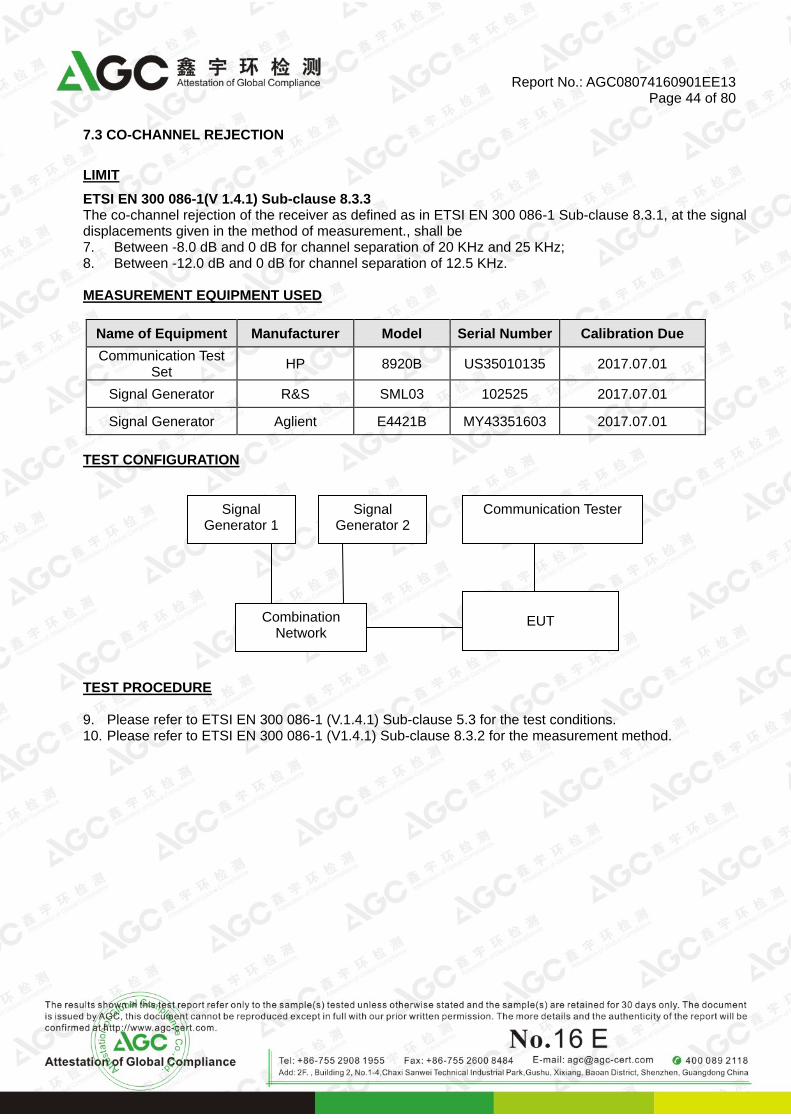
7.3 CO-CHANNEL REJECTION
LIMIT
ETSI EN 300 086-1(V 1.4.1) Sub-clause 8.3.3 The co-channel rejection of the receiver as defined as in ETSI EN 300 086-1 Sub-clause 8.3.1, at the signal displacements given in the method of measurement., shall be 7. Between -8.0 dB and 0 dB for channel separation of 20 KHz and 25 KHz; 8. Between -12.0 dB and 0 dB for channel separation of 12.5 KHz. MEASUREMENT EQUIPMENT USED
Name of Equipment Manufacturer Model Serial Number Calibration Due
Communication Test Set
HP 8920B US35010135 2017.07.01
Signal Generator R&S SML03 102525 2017.07.01
Signal Generator Aglient E4421B MY43351603 2017.07.01
TEST CONFIGURATION
TEST PROCEDURE 9. Please refer to ETSI EN 300 086-1 (V.1.4.1) Sub-clause 5.3 for the test conditions. 10. Please refer to ETSI EN 300 086-1 (V1.4.1) Sub-clause 8.3.2 for the measurement method.
Signal Generator 1
Communication Tester
Combination Network
EUT
Signal Generator 2

Report No.: AGC08074160901EE13 Page 45 of 80
TEST RESULTS
Test Result of 25 KHz Channel Separation
Wanted Signal Channel (MHz)
Unwanted Signal Frequency (MHz)
Test Result ( dB )
Limit ( dB )
Result
400.025 400.025-0.003 -5.46 Between -8.0 dB
and 0 dB Pass
400.025 400.025-0.0015 -6.74 Between -8.0 dB
and 0 dB Pass
400.025 400.025+0.0015 -5.36 Between -8. 0dB
and 0 dB Pass
400.025 400.025+0.003 -5.55 Between -8.0 dB
and 0 dB Pass
Test Result of 25 KHz Channel Separation
Wanted Signal Channel (MHz)
Unwanted Signal Frequency (MHz)
Test Result ( dB )
Limit ( dB )
Result
469.975 469.975-0.003 -5.67 Between -8.0 dB
and 0 dB Pass
469.975 469.975-0.0015 -6.73 Between -8.0 dB
and 0 dB Pass
469.975 469.975+0.0015 -5.42 Between -8. 0dB
and 0 dB Pass
469.975 469.975+0.003 -5.38 Between -8.0 dB
and 0 dB Pass

Report No.: AGC08074160901EE13 Page 46 of 80
Test Result of 12.5 KHz Channel Separation
Wanted Signal Channel (MHz)
Unwanted Signal Frequency (MHz)
Test Result ( dB )
Limit ( dB )
Result
400.025 400.025-0.003 -7.65 Between -12.0 dB
and 0 dB Pass
400.025 400.025-0.0015 -7.46 Between -12.0 dB
and 0 dB Pass
400.025 400.025+0.0015 -8.43 Between -12.0 dB
and 0 dB Pass
400.025 400.025+0.003 -8.64 Between -12.0 dB
and 0 dB Pass
Test Result of 12.5 KHz Channel Separation
Wanted Signal Channel (MHz)
Unwanted Signal Frequency (MHz)
Test Result ( dB )
Limit ( dB )
Result
469.975 469.975-0.003 -7.27 Between -12.0 dB
and 0 dB Pass
469.975 469.975-0.0015 -7.36 Between -12.0 dB
and 0 dB Pass
469.975 469.975+0.0015 -8.24 Between -12.0 dB
and 0 dB Pass
469.975 469.975+0.003 -8.65 Between -12.0 dB
and 0 dB Pass
Report No.: AGC08074160901EE13 Page 47 of 80
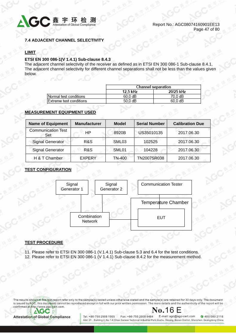
7.4 ADJACENT CHANNEL SELECTIVITY
LIMIT
ETSI EN 300 086-1(V 1.4.1) Sub-clause 8.4.3 The adjacent channel selectivity of the receiver as defined as in ETSI EN 300 086-1 Sub-clause 8.4.1, The adjacent channel selectivity for different channel separations shall not be less than the values given below.
MEASUREMENT EQUIPMENT USED
Name of Equipment Manufacturer Model Serial Number Calibration Due
Communication Test Set
HP 8920B US35010135 2017.06.30
Signal Generator R&S SML03 102525 2017.06.30
Signal Generator R&S SML01 104228 2017.06.30
H & T Chamber EXPERY TN-400 TN2007SR038 2017.06.30
TEST CONFIGURATION
TEST PROCEDURE 11. Please refer to ETSI EN 300 086-1 (V.1.4.1) Sub-clause 5.3 and 6.4 for the test conditions. 12. Please refer to ETSI EN 300 086-1 (V 1.4.1) Sub-clause 8.4.2 for the measurement method.
Temperature Chamber
Signal Generator 1
Communication Tester
Combination Network
EUT
Signal Generator 2

Report No.: AGC08074160901EE13 Page 48 of 80
TEST RESULTS
Test Result of 25 KHz Channel Separation (400.025MHz)
at unwanted signal frequency above wanted signal frequency
Test Condition Result Measured
( dB )
Limit
( dB ) Temperature ( ℃ ) Voltage ( V )
T Nor (25 ℃ ) DC 7.40V 76 70
T min ( -20℃ ) DC 6.29V 64 60
DC 7.40V 73 60
T Max ( 55℃ ) DC 6.29V 74 60
DC 7.40V 75 60
Result Pass
Test Result of 25 KHz Channel Separation (400.025MHz)
at unwanted signal frequency below wanted signal frequency
Test Condition Result Measured
( dB )
Limit
( dB ) Temperature ( ℃ ) Voltage ( V )
T Nor ( 25℃ ) DC 7.40V 82 70
T min ( -20℃ ) DC 6.29V 71 60
DC 7.40V 74 60
T Max (55℃ ) DC 6.29V 72 60
DC 7.40V 65 60
Result Pass

Report No.: AGC08074160901EE13 Page 49 of 80
Test Result of 25 KHz Channel Separation (430.025MHz)
at unwanted signal frequency above wanted signal frequency
Test Condition Result Measured
( dB )
Limit
( dB ) Temperature ( ℃ ) Voltage ( V )
T Nor (25 ℃ ) DC 7.40V 80 70
T min ( -20℃ ) DC 6.29V 73 60
DC 7.40V 68 60
T Max ( 55℃ ) DC 6.29V 67 60
DC 7.40V 71 60
Result Pass
Test Result of 25 KHz Channel Separation (430.025MHz)
at unwanted signal frequency below wanted signal frequency
Test Condition Result Measured
( dB )
Limit
( dB ) Temperature ( ℃ ) Voltage ( V )
T Nor ( 25℃ ) DC 7.40V 81 70
T min ( -20℃ ) DC 6.29V 72 60
DC 7.40V 71 60
T Max (55℃ ) DC 6.29V 73 60
DC 7.40V 72 60
Result Pass

Report No.: AGC08074160901EE13 Page 50 of 80
Test Result of 25 KHz Channel Separation (435.025MHz)
at unwanted signal frequency above wanted signal frequency
Test Condition Result Measured
( dB )
Limit
( dB ) Temperature ( ℃ ) Voltage ( V )
T Nor (25 ℃ ) DC 7.40V 83 70
T min ( -20℃ ) DC 6.29V 72 60
DC 7.40V 71 60
T Max ( 55℃ ) DC 6.29V 69 60
DC 7.40V 74 60
Result Pass
Test Result of 25 KHz Channel Separation (435.025MHz)
at unwanted signal frequency below wanted signal frequency
Test Condition Result Measured
( dB )
Limit
( dB ) Temperature ( ℃ ) Voltage ( V )
T Nor ( 25℃ ) DC 7.40V 82 70
T min ( -20℃ ) DC 6.29V 67 60
DC 7.40V 65 60
T Max (55℃ ) DC 6.29V 73 60
DC 7.40V 72 60
Result Pass

Report No.: AGC08074160901EE13 Page 51 of 80
Test Result of 25 KHz Channel Separation (440.025MHz)
at unwanted signal frequency above wanted signal frequency
Test Condition Result Measured
( dB )
Limit
( dB ) Temperature ( ℃ ) Voltage ( V )
T Nor (25 ℃ ) DC 7.40V 84 70
T min ( -20℃ ) DC 6.29V 72 60
DC 7.40V 71 60
T Max ( 55℃ ) DC 6.29V 67 60
DC 7.40V 68 60
Result Pass
Test Result of 25 KHz Channel Separation (440.025MHz)
at unwanted signal frequency below wanted signal frequency
Test Condition Result Measured
( dB )
Limit
( dB ) Temperature ( ℃ ) Voltage ( V )
T Nor ( 25℃ ) DC 7.40V 76 70
T min ( -20℃ ) DC 6.29V 64 60
DC 7.40V 65 60
T Max (55℃ ) DC 6.29V 70 60
DC 7.40V 71 60
Result Pass

Report No.: AGC08074160901EE13 Page 52 of 80
Test Result of 25 KHz Channel Separation (469.975MHz)
at unwanted signal frequency above wanted signal frequency
Test Condition Result Measured
( dB )
Limit
( dB ) Temperature ( ℃ ) Voltage ( V )
T Nor (25 ℃ ) DC 7.40V 75 70
T min ( -20℃ ) DC 6.29V 73 60
DC 7.40V 72 60
T Max ( 55℃ ) DC 6.29V 74 60
DC 7.40V 71 60
Result Pass
Test Result of 25 KHz Channel Separation (469.975MHz)
at unwanted signal frequency below wanted signal frequency
Test Condition Result Measured
( dB )
Limit
( dB ) Temperature ( ℃ ) Voltage ( V )
T Nor ( 25℃ ) DC 7.40V 77 70
T min ( -20℃ ) DC 6.29V 72 60
DC 7.40V 71 60
T Max (55℃ ) DC 6.29V 73 60
DC 7.40V 74 60
Result Pass

Report No.: AGC08074160901EE13 Page 53 of 80
Test Result of 12.5 KHz Channel Separation (400.025MHz)
at unwanted signal frequency above wanted signal frequency
Test Condition Result Measured
( dB )
Limit
( dB ) Temperature ( ℃ ) Voltage ( V )
T Nor ( 25℃ ) DC 7.40V 72 60
T min ( -20℃ ) DC 6.29V 61 50
DC 7.40V 59 50
T Max ( 55℃ ) DC 6.29V 63 50
DC 7.40V 62 50
Result Pass
Test Result of 12.5 KHz Channel Separation (400.025MHz)
at unwanted signal frequency below wanted signal frequency
Test Condition Result Measured
( dB )
Limit
( dB ) Temperature ( ℃ ) Voltage ( V )
T Nor ( 25℃ ) DC 7.40V 68 60
T min ( -20℃ ) DC 6.29V 63 50
DC 7.40V 61 50
T Max ( 55℃ ) DC 6.29V 62 50
DC 7.40V 61 50
Result Pass

Report No.: AGC08074160901EE13 Page 54 of 80
Test Result of 12.5 KHz Channel Separation (430.025MHz)
at unwanted signal frequency above wanted signal frequency
Test Condition Result Measured
( dB )
Limit
( dB ) Temperature ( ℃ ) Voltage ( V )
T Nor ( 25℃ ) DC 7.40V 71 60
T min ( -20℃ ) DC 6.29V 65 50
DC 7.40V 63 50
T Max ( 55℃ ) DC 6.29V 58 50
DC 7.40V 61 50
Result Pass
Test Result of 12.5 KHz Channel Separation (430.025MHz)
at unwanted signal frequency below wanted signal frequency
Test Condition Result Measured
( dB )
Limit
( dB ) Temperature ( ℃ ) Voltage ( V )
T Nor ( 25℃ ) DC 7.40V 68 60
T min ( -20℃ ) DC 6.29V 63 50
DC 7.40V 60 50
T Max ( 55℃ ) DC 6.29V 61 50
DC 7.40V 62 50
Result Pass

Report No.: AGC08074160901EE13 Page 55 of 80
Test Result of 12.5 KHz Channel Separation (435.025MHz)
at unwanted signal frequency above wanted signal frequency
Test Condition Result Measured
( dB )
Limit
( dB ) Temperature ( ℃ ) Voltage ( V )
T Nor ( 25℃ ) DC 7.40V 67 60
T min ( -20℃ ) DC 6.29V 62 50
DC 7.40V 56 50
T Max ( 55℃ ) DC 6.29V 61 50
DC 7.40V 63 50
Result Pass
Test Result of 12.5 KHz Channel Separation (435.025MHz)
at unwanted signal frequency below wanted signal frequency
Test Condition Result Measured
( dB )
Limit
( dB ) Temperature ( ℃ ) Voltage ( V )
T Nor ( 25℃ ) DC 7.40V 68 60
T min ( -20℃ ) DC 6.29V 59 50
DC 7.40V 56 50
T Max ( 55℃ ) DC 6.29V 63 50
DC 7.40V 62 50
Result Pass

Report No.: AGC08074160901EE13 Page 56 of 80
Test Result of 12.5 KHz Channel Separation (440.025MHz)
at unwanted signal frequency above wanted signal frequency
Test Condition Result Measured
( dB )
Limit
( dB ) Temperature ( ℃ ) Voltage ( V )
T Nor ( 25℃ ) DC 7.40V 73 60
T min ( -20℃ ) DC 6.29V 56 50
DC 7.40V 62 50
T Max ( 55℃ ) DC 6.29V 63 50
DC 7.40V 61 50
Result Pass
Test Result of 12.5 KHz Channel Separation (440.025MHz)
at unwanted signal frequency below wanted signal frequency
Test Condition Result Measured
( dB )
Limit
( dB ) Temperature ( ℃ ) Voltage ( V )
T Nor ( 25℃ ) DC 7.40V 68 60
T min ( -20℃ ) DC 6.29V 64 50
DC 7.40V 59 50
T Max ( 55℃ ) DC 6.29V 62 50
DC 7.40V 57 50
Result Pass

Report No.: AGC08074160901EE13 Page 57 of 80
Test Result of 12.5 KHz Channel Separation (469.975MHz)
at unwanted signal frequency above wanted signal frequency
Test Condition Result Measured
( dB )
Limit
( dB ) Temperature ( ℃ ) Voltage ( V )
T Nor ( 25℃ ) DC 7.40V 74 60
T min ( -20℃ ) DC 6.29V 63 50
DC 7.40V 59 50
T Max ( 55℃ ) DC 6.29V 61 50
DC 7.40V 62 50
Result Pass
Test Result of 12.5 KHz Channel Separation (469.975MHz)
at unwanted signal frequency below wanted signal frequency
Test Condition Result Measured
( dB )
Limit
( dB ) Temperature ( ℃ ) Voltage ( V )
T Nor ( 25℃ ) DC 7.40V 71 60
T min ( -20℃ ) DC 6.29V 59 50
DC 7.40V 62 50
T Max ( 55℃ ) DC 6.29V 63 50
DC 7.40V 61 50
Result Pass

Report No.: AGC08074160901EE13 Page 58 of 80
7.5 SPURIOUS RESPONSE REJECTION
LIMIT
ETSI EN 300 086-1(V 1.4.1) Sub-clause 8.5.4 The spurious response rejection of the receiver as defined as in ETSI EN 300 086-1 Sub-clause 8.5.1, at any frequency separated from the nominal frequency of the receiver by two channels or more, the spurious response rejection ratio shall not be less than 70.0 dB. MEASUREMENT EQUIPMENT USED
Name of Equipment Manufacturer Model Serial Number Calibration
Date Calibration Due
Communication Test Set
HP 8920B US35010135 2016.07.02 2017.07.01
Signal Generator R&S SML03 102525 2016.07.02 2017.07.01
Signal Generator R&S SML01 104228 2016.07.02 2017.07.01
TEST CONFIGURATION The same as described in section 3.7 TEST PROCEDURE 13. Please refer to ETSI EN 300 086-1 (V.1.4.1) Sub-clause 5.3 for the test conditions. 14. Please refer to ETSI EN 300 086-1 (V 1.4.1) Sub-clause 8.5.3 for the measurement method. TEST RESULTS
Test Result of 25 KHz Channel Separation
Test Result ( dB ) Limit ( dB )
81.3 At least 70
Result Pass
Test Result of 12.5 KHz Channel Separation
Test Result ( dB ) Limit ( dB )
82.0 At least 70
Result Pass

Report No.: AGC08074160901EE13 Page 59 of 80
7.6 INTER MODULATION RESPONSE REJECTION
LIMIT
ETSI EN 300 086-1(V 1.4.1) Sub-clause 8.6.3 The inter modulation response rejection of the receiver as defined as in ETSI EN 300 086-1 Sub-clause 8.6.1, shall not be less than the ratio of 70.0 dB for Base Station and 65.0 dB for mobile and hand portable stations. MEASUREMENT EQUIPMENT USED
Name of Equipment Manufacturer Model Serial Number Calibration
Date Calibration Due
Communication Test Set
HP 8920B US35010135 2016.07.02 2017.07.01
Signal Generator R&S SML03 102525 2016.07.02 2017.07.01
Signal Generator R&S SML01 104228 2016.07.02 2017.07.01
Signal Generator Aglient E4421B MY43351603 2016.07.02 2017.07.01
TEST CONFIGURATION
TEST PROCEDURE 15. Please refer to ETSI EN 300 086-1 (V.1.4.1) Sub-clause 5.3 for the test conditions. 16. Please refer to ETSI EN 300 086-1 (V 1.4.1) Sub-clause 8.6.2 for the measurement method.
Signal Generator 1
Communication Tester
Combination Network
EUT
Signal Generator 2
Signal Generator 3

Report No.: AGC08074160901EE13 Page 60 of 80
TEST RESULTS
Test Result of 25 KHz Channel Separation At Above Wanted Signal Channel
Wanted Signal Channel (MHz)
Unmodulated Unwanted Signal
Frequency (MHz)
Modulated Unwanted Signal Frequency
(MHz)
Test Result ( dB )
Limit ( dB )
Result
400.025 400.025+0.025 400.025+0.050 75.6 At least 65.0 Pass
400.025 400.025+0.050 400.025+0.10 74.3 At least 65.0 Pass
Test Result of 25 KHz Channel Separation At Below Wanted Signal Channel
Wanted Signal Channel (MHz)
Unmodulated Unwanted Signal
Frequency (MHz)
Modulated Unwanted Signal Frequency
(MHz)
Test Result ( dB )
Limit ( dB )
Result
400.025 400.025-0.025 400.025-0.050 76.4 At least 65.0 Pass
400.025 400.025-0.050 400.025-0.10 75.5 At least 65.0 Pass
Test Result of 12.5 KHz Channel Separation At Above Wanted Signal Channel
Wanted Signal Channel (MHz)
Unmodulated Unwanted Signal
Frequency (MHz)
Modulated Unwanted Signal Frequency
(MHz)
Test Result ( dB )
Limit ( dB )
Result
400.025 400.025+0.025 400.025+0.050 74.3 At least 65.0 Pass
400.025 400.025+0.050 400.025+0.10 73.6 At least 65.0 Pass
Test Result of 12.5 KHz Channel Separation At Below Wanted Signal Channel
Wanted Signal Channel (MHz)
Unmodulated Unwanted Signal
Frequency (MHz)
Modulated Unwanted Signal Frequency
(MHz)
Test Result ( dB )
Limit ( dB )
Result
400.025 400.025-0.025 400.025-0.050 75.4 At least 65.0 Pass
400.025 400.025-0.050 400.025-0.10 75.1 At least 65.0 Pass

Report No.: AGC08074160901EE13 Page 61 of 80
Test Result of 25 KHz Channel Separation At Above Wanted Signal Channel
Wanted Signal Channel (MHz)
Unmodulated Unwanted Signal
Frequency (MHz)
Modulated Unwanted Signal Frequency
(MHz)
Test Result ( dB )
Limit ( dB )
Result
469.975 469.975+0.025 469.975+0.050 76.7 At least 65.0 Pass
469.975 469.975+0.050 469.975+0.10 75.3 At least 65.0 Pass
Test Result of 25 KHz Channel Separation At Below Wanted Signal Channel
Wanted Signal Channel (MHz)
Unmodulated Unwanted Signal
Frequency (MHz)
Modulated Unwanted Signal Frequency
(MHz)
Test Result ( dB )
Limit ( dB )
Result
469.975 469.975-0.025 469.975-0.050 75.6 At least 65.0 Pass
469.975 469.975-0.050 469.975-0.10 74.4 At least 65.0 Pass
Test Result of 12.5 KHz Channel Separation At Above Wanted Signal Channel
Wanted Signal Channel (MHz)
Unmodulated Unwanted Signal
Frequency (MHz)
Modulated Unwanted Signal Frequency
(MHz)
Test Result ( dB )
Limit ( dB )
Result
469.975 469.975+0.025 469.975+0.050 75.2 At least 65.0 Pass
469.975 469.975+0.050 469.975+0.10 74.5 At least 65.0 Pass
Test Result of 12.5 KHz Channel Separation At Below Wanted Signal Channel
Wanted Signal Channel (MHz)
Unmodulated Unwanted Signal
Frequency (MHz)
Modulated Unwanted Signal Frequency
(MHz)
Test Result ( dB )
Limit ( dB )
Result
469.975 469.975-0.025 469.975-0.050 75.7 At least 65.0 Pass
469.975 469.975 -0.050 469.975-0.10 74.6 At least 65.0 Pass

Report No.: AGC08074160901EE13 Page 62 of 80
7.7 BLOCKING OR DESENSITIZATION
LIMIT
ETSI EN 300 086-1(V 1.4.1) Sub-clause 5.2.8 The blocking or desensitization of the receiver as defined in ETSI EN 300 086-1 Sub-clause 8.7.1, for any frequency within the specified range, shall not be less than 84.0 dB, except at frequencies on which spurious response are found MEASUREMENT EQUIPMENT USED
Name of Equipment Manufacturer Model Serial Number Calibration
Date Calibration Due
Communication Test Set
HP 8920B US35010135 2016.07.02 2017.07.01
Signal Generator R&S SML03 102525 2016.07.02 2017.07.01
Signal Generator R&S SML01 104228 2016.07.02 2017.07.01
TEST CONFIGURATION The same as described in section 7.6 TEST PROCEDURE 17. Please refer to ETSI EN 300 086-1 (V.1.4.1) Sub-clause 5.3 for the test conditions. 18. Please refer to ETSI EN 300 086-1 (V 1.4.1) Sub-clause 8.7.2 for the measurement method. TEST RESULTS

Report No.: AGC08074160901EE13 Page 63 of 80
TEST RESULT
Test Result of 25 KHz Channel Separation At Above Wanted Signal Channel
Wanted Signal Channel (MHz)
Unwanted Signal Frequency
(MHz)
Test Result ( dB )
Limit ( dB )
Result
400.025 400.025+1 89.6 At least 84 Pass
400.025 400.025+2 90.2 At least 84 Pass
400.025 400.025+5 91.7 At least 84 Pass
400.025 400.025+10 92.6 At least 84 Pass
Test Result of 25 KHz Channel Separation At Below Wanted Signal Channel
Wanted Signal Channel (MHz)
Unwanted Signal Frequency
(MHz)
Test Result ( dB )
Limit ( dB )
Result
400.025 400.025-1 89.8 At least 84 Pass
400.025 400.025-2 91.4 At least 84 Pass
400.025 400.025-5 92.1 At least 84 Pass
400.025 400.025-10 93.3 At least 84 Pass
Test Result of 12.5 KHz Channel Separation At Above Wanted Signal Channel
Wanted Signal Channel (MHz)
Unwanted Signal Frequency
(MHz)
Test Result ( dB )
Limit ( dB )
Result
400.025 400.025+1 89.5 At least 84 Pass
400.025 400.025+2 91.6 At least 84 Pass
400.025 400.025+5 92.3 At least 84 Pass
400.025 400.025+10 91.4 At least 84 Pass
Test Result of 12.5 KHz Channel Separation At Below Wanted Signal Channel
Wanted Signal Channel (MHz)
Unwanted Signal Frequency
(MHz)
Test Result ( dB )
Limit ( dB )
Result
400.025 400.025-1 89.7 At least 84 Pass
400.025 400.0250-2 91.3 At least 84 Pass
400.025 400.025-5 92.0 At least 84 Pass
400.025 400.025-10 91.5 At least 84 Pass

Report No.: AGC08074160901EE13 Page 64 of 80
Test Result of 25 KHz Channel Separation At Above Wanted Signal Channel
Wanted Signal Channel (MHz)
Unwanted Signal Frequency
(MHz)
Test Result ( dB )
Limit ( dB )
Result
469.975 469.975+1 89.6 At least 84 Pass
469.975 469.975+2 91.1 At least 84 Pass
469.975 469.975+5 92.3 At least 84 Pass
469.975 469.975+10 92.0 At least 84 Pass
Test Result of 25 KHz Channel Separation At Below Wanted Signal Channel
Wanted Signal Channel (MHz)
Unwanted Signal Frequency
(MHz)
Test Result ( dB )
Limit ( dB )
Result
469.975 469.975-1 89.6 At least 84 Pass
469.975 469.975-2 91.0 At least 84 Pass
469.975 469.975-5 92.5 At least 84 Pass
469.975 469.975-10 93.3 At least 84 Pass
Test Result of 12.5 KHz Channel Separation At Above Wanted Signal Channel
Wanted Signal Channel (MHz)
Unwanted Signal Frequency
(MHz)
Test Result ( dB )
Limit ( dB )
Result
469.975 469.975+1 89.6 At least 84 Pass
469.975 469.975+2 91.3 At least 84 Pass
469.975 469.975+5 92.7 At least 84 Pass
469.975 469.975+10 93.1 At least 84 Pass
Test Result of 12.5 KHz Channel Separation At Below Wanted Signal Channel
Wanted Signal Channel (MHz)
Unwanted Signal Frequency
(MHz)
Test Result ( dB )
Limit ( dB )
Result
469.975 469.975-1 90.6 At least 84 Pass
469.975 469.975-2 91.2 At least 84 Pass
469.975 469.975-5 92.5 At least 84 Pass
469.975 469.975-10 93.0 At least 84 Pass

Report No.: AGC08074160901EE13 Page 65 of 80
7.8 SPURIOUS RADIATIONS
LIMIT
ETSI EN 300 086-1(V 1.4.1) Sub-clause 8.8.4 The spurious radiation of the receiver as defined in ETSI EN 300 086-1 Sub-clause 8.8.1, shall not exceed the values given in tables 7 and 8
Table 7: Conducted components
Frequency Range 9 KHz to 1GHz Above 1GHz to 4GHz, or above 1GHz to 12.75GHz
Limit 2.0 nW (-57 dBm ) 20 nW ( -47 dBm )
Table 8: Radiated emissions
Frequency Range 30 MHz to 1GHz Above 1GHz to 4GHz
Limit 2.0 nW (-57 dBm ) 20 nW ( -47 dBm )
MEASUREMENT EQUIPMENT USED
Radiated Emission Test Site # 4
Name of Equipment Manufacturer Model Serial
Number Calibration
Date Calibration Due
EMI TEST RECEIVER R&S ESCI 10096 2016.07.02 2017.07.01
AMPLIFIER Schwarzbeck BBV 9718 9718-162 2016.07.02 2017.07.01
SPECTRUM ANALYZER
AGILENT N9010A MY53470504 2015.11.09 2016.11.08
ATTENUATOR WEINSCHEL CORP 58-30-33 ML030 2016.07.02 2017.07.01
ANTENNA R&S VULB9168 D69250 2016.03.01 2017.02.28
Double-Ridged Waveguide Horn
ETS LINDGREN 3117 00034609 2016.03.01 2017.02.28
Remark: Each piece of equipment is scheduled for calibration once a year.
TEST CONFIGURATION The same as described in section 6.6 TEST PROCEDURE 19. Please refer to ETSI EN 300 086-1 (V.1.4.1) Sub-clause 5.3 for the test conditions. 20. Please refer to ETSI EN 300 086-1 (V 1.4.1) Sub-clause 8.8.2 and 8.8.3 for the measurement method. TEST RESULTS

Report No.: AGC08074160901EE13 Page 66 of 80
Conducted Measurement (9 KHz to 12.75GHz) --- PASS 400.025MHz with 12.5 KHz channel separation
9KHz-150kHz
150KHz-30MHz

Report No.: AGC08074160901EE13 Page 67 of 80
30MHz-1GHz
1GHz-12.5GHz

Report No.: AGC08074160901EE13 Page 68 of 80
469.975MHz with 25 KHz channel separation 9KHz-150kHz
150KHz-30MHz

Report No.: AGC08074160901EE13 Page 69 of 80
30MHz-1GHz
1GHz-12.5GHz

Report No.: AGC08074160901EE13 Page 70 of 80
The Radiated Measurement are performed to the three channels (the top channel, the middle channel and the top channel) at each channel separation (25 KHz, 12.5 KHz), the datum recorded below is the worst case for each channel separation.
The Bottom Channel is the worst case for 25 KHz Channel Separation
Frequency Reading
level Antenna S.G.
Cable loss
Ant.Gain
Emission level
Limit Margin
(MHz) (dBuV) Polarizatio
n (dBm) (dB) (dB) (dBm) (dBm) (dB)
Below 1 GHz
-- V --
At least 20 dB down than the
limit
Above 1 GHz
-- V --
Below 1 GHz
-- H --
Above 1 GHz
-- H --
Remark:
(1) Emission Level (dBm) = SG O/P-Cable + Ant Gain (2) Measuring frequencies from 30 MHz to the 4GHz.
(3) Data of measurement within this frequency range shown “ -- ” in the table above means the reading of emissions are attenuated more than 20dB below the permissible limits or the field strength is too small to be measured.

Report No.: AGC08074160901EE13 Page 71 of 80
The Bottom Channel is the worst case for 12.5 KHz Channel Separation
Frequency Reading
level Antenna S.G.
Cable loss
Ant.Gain
Emission level
Limit Margin
(MHz) (dBuV) Polarizatio
n (dBm) (dB) (dB) (dBm) (dBm) (dB)
Below 1 GHz
-- V --
At least 20 dB down than the
limit
Above 1 GHz
-- V --
Below 1 GHz
-- H --
Above 1 GHz
-- H --
Remark:
(1) Emission Level (dBm) = SG O/P-Cable + Ant Gain (2) Measuring frequencies from 30 MHz to the 4GHz.
(3) Data of measurement within this frequency range shown “ -- ” in the table above means the reading of emissions are attenuated more than 20dB below the permissible limits or the field strength is too small to be measured.

Report No.: AGC08074160901EE13 Page 72 of 80
8. DUPLEX OPERATION (NOT APPLICABLE)
8.1 RECEIVER DESENSITIZATION (WITH SIMULTANEOUS TRANSMISSION AND RECEPTION)
LIMIT
ETSI EN 300 086-1(V 1.4.1) Sub-clause 9.1.4 The desensitization is defined in ETSI EN 300 086-1 Sub-clause 9.1.1, shall not exceed 3.0 dB and the limit of maximum usable sensitivity under normal test conditions shall be met. MEASUREMENT EQUIPMENT USED
Name of Equipment Manufacturer Model Serial Number Calibration
Date Calibration Due
Communication Test Set
HP 8920B US35010135 2016.07.01 2017.06.30
Signal Generator Aglient E4421B MY43351603 2016.07.01 2017.06.30
TEST CONFIGURATION
TEST PROCEDURE 21. Please refer to ETSI EN 300 086-1 (V.1.4.1) Sub-clause 5.3 for the test conditions. 22. Please refer to ETSI EN 300 086-1 (V 1.4.1) Sub-clause 9.1.2 and 9.1.3 for the measurement method.
TEST RESULTS N/A
Signal Generator
Communication Tester
Combination Network
EUT

Report No.: AGC08074160901EE13 Page 73 of 80
8.2 RECEIVER SPURIOUS RESPONSE REJECTION (WITH SIMULTANEOUS TRANSMISSION AND
RECEPTION)
LIMIT
ETSI EN 300 086-1(V 1.4.1) Sub-clause 9.2.3 The spurious response rejection under duplex operation is a measure of the capability of the receiver to achieve a specific spurious response rejection ration when receiving a wanted modulated signal in the presence of: 23. an unwanted signal at any other frequency, at which a response may be obtained; and 24. the unmodulated signal of the transmitter operation at duplex frequency distance, at the rated output
power and attenuated by the duplex filter or by the distance between the antennas. At any frequency separated from the nominal frequency of the receiver by two channels or more, the spurious response rejection ration shall be greater than 67.0 dB.
MEASUREMENT EQUIPMENT USED
Name of Equipment Manufacturer Model Serial Number Calibration
Date Calibration Due
Communication Test Set
HP 8920B US35010135 2016.07.01 2017.06.30
Signal Generator R&S SML03 102525 2016.07.01 2017.06.30
Signal Generator Aglient E4421B MY43351603 2016.07.01 2017.06.30
TEST CONFIGURATION
TEST PROCEDURE 25. Please refer to ETSI EN 300 086-1 (V.1.4.1) Sub-clause 5.3 for the test conditions. 26. Please refer to ETSI EN 300 086-1 (V 1.4.1) Sub-clause 9.2.2 for the measurement method.
TEST RESULTS N/A
Signal Generator 1
Communication Tester
Combination Network
EUT
Signal Generator 2

Report No.: AGC08074160901EE13 Page 74 of 80
APPENDIX 1:HOTOGRAPHS OF TEST SETUP
RADIATED SPURIOUS EMISSION TEST SETUP

Report No.: AGC08074160901EE13 Page 75 of 80
APPENDIX 2:HOTOGRAPHS OF EUT
TOTAL VIEW OF EUT
TOP VIEW OF EUT

Report No.: AGC08074160901EE13 Page 76 of 80
BOTTOM VIEW OF EUT
FRONT VIEW OF EUT

Report No.: AGC08074160901EE13 Page 77 of 80
BACK VIEW OF EUT
LEFT VIEW OF EUT

Report No.: AGC08074160901EE13 Page 78 of 80
RIGHT VIEW OF EUT
OPEN VIEW-1 OF EUT

Report No.: AGC08074160901EE13 Page 79 of 80
OPEN VIEW-2 OF EUT
OPEN VIEW-3 OF EUT

Report No.: AGC08074160901EE13 Page 80 of 80
INTERNAL VIEW-1 OF EUT
INTERNAL VIEW-2 OF EUT
---END OF REPORT--