rfc 9000: quic: a udp-based multiplexed and secure transport
TRANSCRIPT

RFC 9000QUIC: A UDP-Based Multiplexed and SecureTransport
AbstractThis document defines the core of the QUIC transport protocol. QUIC provides applications withflow-controlled streams for structured communication, low-latency connection establishment,and network path migration. QUIC includes security measures that ensure confidentiality,integrity, and availability in a range of deployment circumstances. Accompanying documentsdescribe the integration of TLS for key negotiation, loss detection, and an exemplary congestioncontrol algorithm.
Stream: Internet Engineering Task Force (IETF)RFC: 9000Category: Standards TrackPublished: May 2021 ISSN: 2070-1721Authors: J. Iyengar, Ed.
FastlyM. Thomson, Ed.Mozilla
Status of This Memo This is an Internet Standards Track document.
This document is a product of the Internet Engineering Task Force (IETF). It represents theconsensus of the IETF community. It has received public review and has been approved forpublication by the Internet Engineering Steering Group (IESG). Further information on InternetStandards is available in Section 2 of RFC 7841.
Information about the current status of this document, any errata, and how to provide feedbackon it may be obtained at .https://www.rfc-editor.org/info/rfc9000
Copyright Notice Copyright (c) 2021 IETF Trust and the persons identified as the document authors. All rightsreserved.
This document is subject to BCP 78 and the IETF Trust's Legal Provisions Relating to IETFDocuments ( ) in effect on the date of publication of thisdocument. Please review these documents carefully, as they describe your rights and restrictions
https://trustee.ietf.org/license-info
Iyengar & Thomson Standards Track Page 1

with respect to this document. Code Components extracted from this document must includeSimplified BSD License text as described in Section 4.e of the Trust Legal Provisions and areprovided without warranty as described in the Simplified BSD License.
Table of Contents 1. Overview
1.1. Document Structure
1.2. Terms and Definitions
1.3. Notational Conventions
2. Streams
2.1. Stream Types and Identifiers
2.2. Sending and Receiving Data
2.3. Stream Prioritization
2.4. Operations on Streams
3. Stream States
3.1. Sending Stream States
3.2. Receiving Stream States
3.3. Permitted Frame Types
3.4. Bidirectional Stream States
3.5. Solicited State Transitions
4. Flow Control
4.1. Data Flow Control
4.2. Increasing Flow Control Limits
4.3. Flow Control Performance
4.4. Handling Stream Cancellation
4.5. Stream Final Size
4.6. Controlling Concurrency
5. Connections
5.1. Connection ID
5.1.1. Issuing Connection IDs
5.1.2. Consuming and Retiring Connection IDs
RFC 9000 QUIC Transport Protocol May 2021
Iyengar & Thomson Standards Track Page 2

5.2. Matching Packets to Connections
5.2.1. Client Packet Handling
5.2.2. Server Packet Handling
5.2.3. Considerations for Simple Load Balancers
5.3. Operations on Connections
6. Version Negotiation
6.1. Sending Version Negotiation Packets
6.2. Handling Version Negotiation Packets
6.3. Using Reserved Versions
7. Cryptographic and Transport Handshake
7.1. Example Handshake Flows
7.2. Negotiating Connection IDs
7.3. Authenticating Connection IDs
7.4. Transport Parameters
7.4.1. Values of Transport Parameters for 0-RTT
7.4.2. New Transport Parameters
7.5. Cryptographic Message Buffering
8. Address Validation
8.1. Address Validation during Connection Establishment
8.1.1. Token Construction
8.1.2. Address Validation Using Retry Packets
8.1.3. Address Validation for Future Connections
8.1.4. Address Validation Token Integrity
8.2. Path Validation
8.2.1. Initiating Path Validation
8.2.2. Path Validation Responses
8.2.3. Successful Path Validation
8.2.4. Failed Path Validation
9. Connection Migration
9.1. Probing a New Path
RFC 9000 QUIC Transport Protocol May 2021
Iyengar & Thomson Standards Track Page 3

9.2. Initiating Connection Migration
9.3. Responding to Connection Migration
9.3.1. Peer Address Spoofing
9.3.2. On-Path Address Spoofing
9.3.3. Off-Path Packet Forwarding
9.4. Loss Detection and Congestion Control
9.5. Privacy Implications of Connection Migration
9.6. Server's Preferred Address
9.6.1. Communicating a Preferred Address
9.6.2. Migration to a Preferred Address
9.6.3. Interaction of Client Migration and Preferred Address
9.7. Use of IPv6 Flow Label and Migration
10. Connection Termination
10.1. Idle Timeout
10.1.1. Liveness Testing
10.1.2. Deferring Idle Timeout
10.2. Immediate Close
10.2.1. Closing Connection State
10.2.2. Draining Connection State
10.2.3. Immediate Close during the Handshake
10.3. Stateless Reset
10.3.1. Detecting a Stateless Reset
10.3.2. Calculating a Stateless Reset Token
10.3.3. Looping
11. Error Handling
11.1. Connection Errors
11.2. Stream Errors
12. Packets and Frames
12.1. Protected Packets
12.2. Coalescing Packets
RFC 9000 QUIC Transport Protocol May 2021
Iyengar & Thomson Standards Track Page 4

12.3. Packet Numbers
12.4. Frames and Frame Types
12.5. Frames and Number Spaces
13. Packetization and Reliability
13.1. Packet Processing
13.2. Generating Acknowledgments
13.2.1. Sending ACK Frames
13.2.2. Acknowledgment Frequency
13.2.3. Managing ACK Ranges
13.2.4. Limiting Ranges by Tracking ACK Frames
13.2.5. Measuring and Reporting Host Delay
13.2.6. ACK Frames and Packet Protection
13.2.7. PADDING Frames Consume Congestion Window
13.3. Retransmission of Information
13.4. Explicit Congestion Notification
13.4.1. Reporting ECN Counts
13.4.2. ECN Validation
14. Datagram Size
14.1. Initial Datagram Size
14.2. Path Maximum Transmission Unit
14.2.1. Handling of ICMP Messages by PMTUD
14.3. Datagram Packetization Layer PMTU Discovery
14.3.1. DPLPMTUD and Initial Connectivity
14.3.2. Validating the Network Path with DPLPMTUD
14.3.3. Handling of ICMP Messages by DPLPMTUD
14.4. Sending QUIC PMTU Probes
14.4.1. PMTU Probes Containing Source Connection ID
15. Versions
16. Variable-Length Integer Encoding
RFC 9000 QUIC Transport Protocol May 2021
Iyengar & Thomson Standards Track Page 5

17. Packet Formats
17.1. Packet Number Encoding and Decoding
17.2. Long Header Packets
17.2.1. Version Negotiation Packet
17.2.2. Initial Packet
17.2.3. 0-RTT
17.2.4. Handshake Packet
17.2.5. Retry Packet
17.3. Short Header Packets
17.3.1. 1-RTT Packet
17.4. Latency Spin Bit
18. Transport Parameter Encoding
18.1. Reserved Transport Parameters
18.2. Transport Parameter Definitions
19. Frame Types and Formats
19.1. PADDING Frames
19.2. PING Frames
19.3. ACK Frames
19.3.1. ACK Ranges
19.3.2. ECN Counts
19.4. RESET_STREAM Frames
19.5. STOP_SENDING Frames
19.6. CRYPTO Frames
19.7. NEW_TOKEN Frames
19.8. STREAM Frames
19.9. MAX_DATA Frames
19.10. MAX_STREAM_DATA Frames
19.11. MAX_STREAMS Frames
19.12. DATA_BLOCKED Frames
19.13. STREAM_DATA_BLOCKED Frames
RFC 9000 QUIC Transport Protocol May 2021
Iyengar & Thomson Standards Track Page 6

19.14. STREAMS_BLOCKED Frames
19.15. NEW_CONNECTION_ID Frames
19.16. RETIRE_CONNECTION_ID Frames
19.17. PATH_CHALLENGE Frames
19.18. PATH_RESPONSE Frames
19.19. CONNECTION_CLOSE Frames
19.20. HANDSHAKE_DONE Frames
19.21. Extension Frames
20. Error Codes
20.1. Transport Error Codes
20.2. Application Protocol Error Codes
21. Security Considerations
21.1. Overview of Security Properties
21.1.1. Handshake
21.1.2. Protected Packets
21.1.3. Connection Migration
21.2. Handshake Denial of Service
21.3. Amplification Attack
21.4. Optimistic ACK Attack
21.5. Request Forgery Attacks
21.5.1. Control Options for Endpoints
21.5.2. Request Forgery with Client Initial Packets
21.5.3. Request Forgery with Preferred Addresses
21.5.4. Request Forgery with Spoofed Migration
21.5.5. Request Forgery with Version Negotiation
21.5.6. Generic Request Forgery Countermeasures
21.6. Slowloris Attacks
21.7. Stream Fragmentation and Reassembly Attacks
21.8. Stream Commitment Attack
21.9. Peer Denial of Service
RFC 9000 QUIC Transport Protocol May 2021
Iyengar & Thomson Standards Track Page 7
21.10. Explicit Congestion Notification Attacks
21.11. Stateless Reset Oracle
21.12. Version Downgrade
21.13. Targeted Attacks by Routing
21.14. Traffic Analysis
22. IANA Considerations
22.1. Registration Policies for QUIC Registries
22.1.1. Provisional Registrations
22.1.2. Selecting Codepoints
22.1.3. Reclaiming Provisional Codepoints
22.1.4. Permanent Registrations
22.2. QUIC Versions Registry
22.3. QUIC Transport Parameters Registry
22.4. QUIC Frame Types Registry
22.5. QUIC Transport Error Codes Registry
23. References
23.1. Normative References
23.2. Informative References
Appendix A. Pseudocode
A.1. Sample Variable-Length Integer Decoding
A.2. Sample Packet Number Encoding Algorithm
A.3. Sample Packet Number Decoding Algorithm
A.4. Sample ECN Validation Algorithm
Contributors
Authors' Addresses
1. Overview QUIC is a secure general-purpose transport protocol. This document defines version 1 of QUIC,which conforms to the version-independent properties of QUIC defined in .[QUIC-INVARIANTS]
RFC 9000 QUIC Transport Protocol May 2021
Iyengar & Thomson Standards Track Page 8

QUIC is a connection-oriented protocol that creates a stateful interaction between a client andserver.
The QUIC handshake combines negotiation of cryptographic and transport parameters. QUICintegrates the TLS handshake , although using a customized framing for protectingpackets. The integration of TLS and QUIC is described in more detail in . Thehandshake is structured to permit the exchange of application data as soon as possible. Thisincludes an option for clients to send data immediately (0-RTT), which requires some form ofprior communication or configuration to enable.
Endpoints communicate in QUIC by exchanging QUIC packets. Most packets contain frames,which carry control information and application data between endpoints. QUIC authenticates theentirety of each packet and encrypts as much of each packet as is practical. QUIC packets arecarried in UDP datagrams to better facilitate deployment in existing systems and networks.
Application protocols exchange information over a QUIC connection via streams, which areordered sequences of bytes. Two types of streams can be created: bidirectional streams, whichallow both endpoints to send data; and unidirectional streams, which allow a single endpoint tosend data. A credit-based scheme is used to limit stream creation and to bound the amount ofdata that can be sent.
QUIC provides the necessary feedback to implement reliable delivery and congestion control. Analgorithm for detecting and recovering from loss of data is described in
. QUIC depends on congestion control to avoid network congestion. An exemplarycongestion control algorithm is described in .
QUIC connections are not strictly bound to a single network path. Connection migration usesconnection identifiers to allow connections to transfer to a new network path. Only clients areable to migrate in this version of QUIC. This design also allows connections to continue afterchanges in network topology or address mappings, such as might be caused by NAT rebinding.
Once established, multiple options are provided for connection termination. Applications canmanage a graceful shutdown, endpoints can negotiate a timeout period, errors can causeimmediate connection teardown, and a stateless mechanism provides for termination ofconnections after one endpoint has lost state.
[TLS13][QUIC-TLS]
[UDP]
Section 6 of [QUIC-RECOVERY]
Section 7 of [QUIC-RECOVERY]
1.1. Document Structure This document describes the core QUIC protocol and is structured as follows:
Streams are the basic service abstraction that QUIC provides.Section 2 describes core concepts related to streams, Section 3 provides a reference model for stream states, and Section 4 outlines the operation of flow control.
Connections are the context in which QUIC endpoints communicate.Section 5 describes core concepts related to connections,
• ◦
◦
◦
• ◦
RFC 9000 QUIC Transport Protocol May 2021
Iyengar & Thomson Standards Track Page 9

Section 6 describes version negotiation, Section 7 details the process for establishing connections, Section 8 describes address validation and critical denial-of-service mitigations, Section 9 describes how endpoints migrate a connection to a new network path, Section 10 lists the options for terminating an open connection, and Section 11 provides guidance for stream and connection error handling.
Packets and frames are the basic unit used by QUIC to communicate.Section 12 describes concepts related to packets and frames, Section 13 defines models for the transmission, retransmission, and acknowledgment ofdata, and Section 14 specifies rules for managing the size of datagrams carrying QUIC packets.
Finally, encoding details of QUIC protocol elements are described in:Section 15 (versions), Section 16 (integer encoding), Section 17 (packet headers), Section 18 (transport parameters), Section 19 (frames), and Section 20 (errors).
Accompanying documents describe QUIC's loss detection and congestion control , and the use of TLS and other cryptographic mechanisms .
This document defines QUIC version 1, which conforms to the protocol invariants in .
To refer to QUIC version 1, cite this document. References to the limited set of version-independent properties of QUIC can cite .
◦
◦
◦
◦
◦
◦
• ◦
◦
◦
• ◦
◦
◦
◦
◦
◦
[QUIC-RECOVERY] [QUIC-TLS]
[QUIC-INVARIANTS]
[QUIC-INVARIANTS]
QUIC:
Endpoint:
Client:
1.2. Terms and Definitions The key words " ", " ", " ", " ", " ", " ", "
", " ", " ", " ", and " " in this document are tobe interpreted as described in BCP 14 when, and only when, they appear inall capitals, as shown here.
Commonly used terms in this document are described below.
The transport protocol described by this document. QUIC is a name, not an acronym.
An entity that can participate in a QUIC connection by generating, receiving, andprocessing QUIC packets. There are only two types of endpoints in QUIC: client and server.
The endpoint that initiates a QUIC connection.
MUST MUST NOT REQUIRED SHALL SHALL NOT SHOULD SHOULDNOT RECOMMENDED NOT RECOMMENDED MAY OPTIONAL
[RFC2119] [RFC8174]
RFC 9000 QUIC Transport Protocol May 2021
Iyengar & Thomson Standards Track Page 10

Server:
QUIC packet:
Ack-eliciting packet:
Frame:
Address:
Connection ID:
Stream:
Application:
The endpoint that accepts a QUIC connection.
A complete processable unit of QUIC that can be encapsulated in a UDP datagram.One or more QUIC packets can be encapsulated in a single UDP datagram.
A QUIC packet that contains frames other than ACK, PADDING, andCONNECTION_CLOSE. These cause a recipient to send an acknowledgment; see Section 13.2.1.
A unit of structured protocol information. There are multiple frame types, each ofwhich carries different information. Frames are contained in QUIC packets.
When used without qualification, the tuple of IP version, IP address, and UDP portnumber that represents one end of a network path.
An identifier that is used to identify a QUIC connection at an endpoint. Eachendpoint selects one or more connection IDs for its peer to include in packets sent towardsthe endpoint. This value is opaque to the peer.
A unidirectional or bidirectional channel of ordered bytes within a QUIC connection. AQUIC connection can carry multiple simultaneous streams.
An entity that uses QUIC to send and receive data.
This document uses the terms "QUIC packets", "UDP datagrams", and "IP packets" to refer to theunits of the respective protocols. That is, one or more QUIC packets can be encapsulated in a UDPdatagram, which is in turn encapsulated in an IP packet.
x (A):
x (i):
x (A..B):
1.3. Notational Conventions Packet and frame diagrams in this document use a custom format. The purpose of this format isto summarize, not define, protocol elements. Prose defines the complete semantics and details ofstructures.
Complex fields are named and then followed by a list of fields surrounded by a pair of matchingbraces. Each field in this list is separated by commas.
Individual fields include length information, plus indications about fixed value, optionality, orrepetitions. Individual fields use the following notational conventions, with all lengths in bits:
Indicates that x is A bits long
Indicates that x holds an integer value using the variable-length encoding described in Section 16
Indicates that x can be any length from A to B; A can be omitted to indicate a minimumof zero bits, and B can be omitted to indicate no set upper limit; values in this format alwaysend on a byte boundary
RFC 9000 QUIC Transport Protocol May 2021
Iyengar & Thomson Standards Track Page 11

x (L) = C:
x (L) = C..D:
[x (L)]:
x (L) ...:
Indicates that x has a fixed value of C; the length of x is described by L, which can useany of the length forms above
Indicates that x has a value in the range from C to D, inclusive, with the lengthdescribed by L, as above
Indicates that x is optional and has a length of L
Indicates that x is repeated zero or more times and that each instance has a length of L
This document uses network byte order (that is, big endian) values. Fields are placed startingfrom the high-order bits of each byte.
By convention, individual fields reference a complex field by using the name of the complexfield.
Figure 1 provides an example:
When a single-bit field is referenced in prose, the position of that field can be clarified by usingthe value of the byte that carries the field with the field's value set. For example, the value 0x80could be used to refer to the single-bit field in the most significant bit of the byte, such as One-bitField in Figure 1.
Figure 1: Example Format
Example Structure { One-bit Field (1), 7-bit Field with Fixed Value (7) = 61, Field with Variable-Length Integer (i), Arbitrary-Length Field (..), Variable-Length Field (8..24), Field With Minimum Length (16..), Field With Maximum Length (..128), [Optional Field (64)], Repeated Field (8) ...,}
2. Streams Streams in QUIC provide a lightweight, ordered byte-stream abstraction to an application.Streams can be unidirectional or bidirectional.
Streams can be created by sending data. Other processes associated with stream management --ending, canceling, and managing flow control -- are all designed to impose minimal overheads.For instance, a single STREAM frame (Section 19.8) can open, carry data for, and close a stream.Streams can also be long-lived and can last the entire duration of a connection.
RFC 9000 QUIC Transport Protocol May 2021
Iyengar & Thomson Standards Track Page 12

Streams can be created by either endpoint, can concurrently send data interleaved with otherstreams, and can be canceled. QUIC does not provide any means of ensuring ordering betweenbytes on different streams.
QUIC allows for an arbitrary number of streams to operate concurrently and for an arbitraryamount of data to be sent on any stream, subject to flow control constraints and stream limits;see Section 4.
2.1. Stream Types and Identifiers Streams can be unidirectional or bidirectional. Unidirectional streams carry data in onedirection: from the initiator of the stream to its peer. Bidirectional streams allow for data to besent in both directions.
Streams are identified within a connection by a numeric value, referred to as the stream ID. Astream ID is a 62-bit integer (0 to 262-1) that is unique for all streams on a connection. Stream IDsare encoded as variable-length integers; see Section 16. A QUIC endpoint reuse astream ID within a connection.
The least significant bit (0x01) of the stream ID identifies the initiator of the stream. Client-initiated streams have even-numbered stream IDs (with the bit set to 0), and server-initiatedstreams have odd-numbered stream IDs (with the bit set to 1).
The second least significant bit (0x02) of the stream ID distinguishes between bidirectionalstreams (with the bit set to 0) and unidirectional streams (with the bit set to 1).
The two least significant bits from a stream ID therefore identify a stream as one of four types, assummarized in Table 1.
The stream space for each type begins at the minimum value (0x00 through 0x03, respectively);successive streams of each type are created with numerically increasing stream IDs. A stream IDthat is used out of order results in all streams of that type with lower-numbered stream IDs alsobeing opened.
MUST NOT
Bits Stream Type
0x00 Client-Initiated, Bidirectional
0x01 Server-Initiated, Bidirectional
0x02 Client-Initiated, Unidirectional
0x03 Server-Initiated, Unidirectional
Table 1: Stream ID Types
RFC 9000 QUIC Transport Protocol May 2021
Iyengar & Thomson Standards Track Page 13

2.2. Sending and Receiving Data STREAM frames (Section 19.8) encapsulate data sent by an application. An endpoint uses theStream ID and Offset fields in STREAM frames to place data in order.
Endpoints be able to deliver stream data to an application as an ordered byte stream.Delivering an ordered byte stream requires that an endpoint buffer any data that is received outof order, up to the advertised flow control limit.
QUIC makes no specific allowances for delivery of stream data out of order. However,implementations choose to offer the ability to deliver data out of order to a receivingapplication.
An endpoint could receive data for a stream at the same stream offset multiple times. Data thathas already been received can be discarded. The data at a given offset change if it issent multiple times; an endpoint treat receipt of different data at the same offset within astream as a connection error of type PROTOCOL_VIOLATION.
Streams are an ordered byte-stream abstraction with no other structure visible to QUIC. STREAMframe boundaries are not expected to be preserved when data is transmitted, retransmitted afterpacket loss, or delivered to the application at a receiver.
An endpoint send data on any stream without ensuring that it is within the flowcontrol limits set by its peer. Flow control is described in detail in Section 4.
MUST
MAY
MUST NOTMAY
MUST NOT
2.3. Stream Prioritization Stream multiplexing can have a significant effect on application performance if resourcesallocated to streams are correctly prioritized.
QUIC does not provide a mechanism for exchanging prioritization information. Instead, it relieson receiving priority information from the application.
A QUIC implementation provide ways in which an application can indicate the relativepriority of streams. An implementation uses information provided by the application todetermine how to allocate resources to active streams.
SHOULD
2.4. Operations on Streams This document does not define an API for QUIC; it instead defines a set of functions on streamsthat application protocols can rely upon. An application protocol can assume that a QUICimplementation provides an interface that includes the operations described in this section. Animplementation designed for use with a specific application protocol might provide only thoseoperations that are used by that protocol.
RFC 9000 QUIC Transport Protocol May 2021
Iyengar & Thomson Standards Track Page 14

On the sending part of a stream, an application protocol can:
write data, understanding when stream flow control credit (Section 4.1) has successfullybeen reserved to send the written data; end the stream (clean termination), resulting in a STREAM frame (Section 19.8) with the FINbit set; and reset the stream (abrupt termination), resulting in a RESET_STREAM frame (Section 19.4) ifthe stream was not already in a terminal state.
On the receiving part of a stream, an application protocol can:
read data; and abort reading of the stream and request closure, possibly resulting in a STOP_SENDINGframe (Section 19.5).
An application protocol can also request to be informed of state changes on streams, includingwhen the peer has opened or reset a stream, when a peer aborts reading on a stream, when newdata is available, and when data can or cannot be written to the stream due to flow control.
•
•
•
• •
3. Stream States This section describes streams in terms of their send or receive components. Two state machinesare described: one for the streams on which an endpoint transmits data (Section 3.1) and anotherfor streams on which an endpoint receives data (Section 3.2).
Unidirectional streams use either the sending or receiving state machine, depending on thestream type and endpoint role. Bidirectional streams use both state machines at both endpoints.For the most part, the use of these state machines is the same whether the stream isunidirectional or bidirectional. The conditions for opening a stream are slightly more complexfor a bidirectional stream because the opening of either the send or receive side causes thestream to open in both directions.
The state machines shown in this section are largely informative. This document uses streamstates to describe rules for when and how different types of frames can be sent and the reactionsthat are expected when different types of frames are received. Though these state machines areintended to be useful in implementing QUIC, these states are not intended to constrainimplementations. An implementation can define a different state machine as long as its behavioris consistent with an implementation that implements these states.
Note: In some cases, a single event or action can cause a transition through multiplestates. For instance, sending STREAM with a FIN bit set can cause two statetransitions for a sending stream: from the "Ready" state to the "Send" state, andfrom the "Send" state to the "Data Sent" state.
RFC 9000 QUIC Transport Protocol May 2021
Iyengar & Thomson Standards Track Page 15

3.1. Sending Stream States Figure 2 shows the states for the part of a stream that sends data to a peer.
The sending part of a stream that the endpoint initiates (types 0 and 2 for clients, 1 and 3 forservers) is opened by the application. The "Ready" state represents a newly created stream that isable to accept data from the application. Stream data might be buffered in this state inpreparation for sending.
Sending the first STREAM or STREAM_DATA_BLOCKED frame causes a sending part of a streamto enter the "Send" state. An implementation might choose to defer allocating a stream ID to astream until it sends the first STREAM frame and enters this state, which can allow for betterstream prioritization.
The sending part of a bidirectional stream initiated by a peer (type 0 for a server, type 1 for aclient) starts in the "Ready" state when the receiving part is created.
Figure 2: States for Sending Parts of Streams
o | Create Stream (Sending) | Peer Creates Bidirectional Stream v +-------+ | Ready | Send RESET_STREAM | |-----------------------. +-------+ | | | | Send STREAM / | | STREAM_DATA_BLOCKED | v | +-------+ | | Send | Send RESET_STREAM | | |---------------------->| +-------+ | | | | Send STREAM + FIN | v v +-------+ +-------+ | Data | Send RESET_STREAM | Reset | | Sent |------------------>| Sent | +-------+ +-------+ | | | Recv All ACKs | Recv ACK v v +-------+ +-------+ | Data | | Reset | | Recvd | | Recvd | +-------+ +-------+
RFC 9000 QUIC Transport Protocol May 2021
Iyengar & Thomson Standards Track Page 16

In the "Send" state, an endpoint transmits -- and retransmits as necessary -- stream data inSTREAM frames. The endpoint respects the flow control limits set by its peer and continues toaccept and process MAX_STREAM_DATA frames. An endpoint in the "Send" state generatesSTREAM_DATA_BLOCKED frames if it is blocked from sending by stream flow control limits(Section 4.1).
After the application indicates that all stream data has been sent and a STREAM framecontaining the FIN bit is sent, the sending part of the stream enters the "Data Sent" state. Fromthis state, the endpoint only retransmits stream data as necessary. The endpoint does not need tocheck flow control limits or send STREAM_DATA_BLOCKED frames for a stream in this state.MAX_STREAM_DATA frames might be received until the peer receives the final stream offset. Theendpoint can safely ignore any MAX_STREAM_DATA frames it receives from its peer for a streamin this state.
Once all stream data has been successfully acknowledged, the sending part of the stream entersthe "Data Recvd" state, which is a terminal state.
From any state that is one of "Ready", "Send", or "Data Sent", an application can signal that itwishes to abandon transmission of stream data. Alternatively, an endpoint might receive aSTOP_SENDING frame from its peer. In either case, the endpoint sends a RESET_STREAM frame,which causes the stream to enter the "Reset Sent" state.
An endpoint send a RESET_STREAM as the first frame that mentions a stream; this causesthe sending part of that stream to open and then immediately transition to the "Reset Sent" state.
Once a packet containing a RESET_STREAM has been acknowledged, the sending part of thestream enters the "Reset Recvd" state, which is a terminal state.
MAY
3.2. Receiving Stream States Figure 3 shows the states for the part of a stream that receives data from a peer. The states for areceiving part of a stream mirror only some of the states of the sending part of the stream at thepeer. The receiving part of a stream does not track states on the sending part that cannot beobserved, such as the "Ready" state. Instead, the receiving part of a stream tracks the delivery ofdata to the application, some of which cannot be observed by the sender.
RFC 9000 QUIC Transport Protocol May 2021
Iyengar & Thomson Standards Track Page 17

The receiving part of a stream initiated by a peer (types 1 and 3 for a client, or 0 and 2 for aserver) is created when the first STREAM, STREAM_DATA_BLOCKED, or RESET_STREAM frame isreceived for that stream. For bidirectional streams initiated by a peer, receipt of aMAX_STREAM_DATA or STOP_SENDING frame for the sending part of the stream also creates thereceiving part. The initial state for the receiving part of a stream is "Recv".
For a bidirectional stream, the receiving part enters the "Recv" state when the sending partinitiated by the endpoint (type 0 for a client, type 1 for a server) enters the "Ready" state.
An endpoint opens a bidirectional stream when a MAX_STREAM_DATA or STOP_SENDING frameis received from the peer for that stream. Receiving a MAX_STREAM_DATA frame for anunopened stream indicates that the remote peer has opened the stream and is providing flowcontrol credit. Receiving a STOP_SENDING frame for an unopened stream indicates that theremote peer no longer wishes to receive data on this stream. Either frame might arrive before aSTREAM or STREAM_DATA_BLOCKED frame if packets are lost or reordered.
Before a stream is created, all streams of the same type with lower-numbered stream IDs be created. This ensures that the creation order for streams is consistent on both endpoints.
Figure 3: States for Receiving Parts of Streams
o | Recv STREAM / STREAM_DATA_BLOCKED / RESET_STREAM | Create Bidirectional Stream (Sending) | Recv MAX_STREAM_DATA / STOP_SENDING (Bidirectional) | Create Higher-Numbered Stream v +-------+ | Recv | Recv RESET_STREAM | |-----------------------. +-------+ | | | | Recv STREAM + FIN | v | +-------+ | | Size | Recv RESET_STREAM | | Known |---------------------->| +-------+ | | | | Recv All Data | v v +-------+ Recv RESET_STREAM +-------+ | Data |--- (optional) --->| Reset | | Recvd | Recv All Data | Recvd | +-------+<-- (optional) ----+-------+ | | | App Read All Data | App Read Reset v v +-------+ +-------+ | Data | | Reset | | Read | | Read | +-------+ +-------+
MUST
RFC 9000 QUIC Transport Protocol May 2021
Iyengar & Thomson Standards Track Page 18

In the "Recv" state, the endpoint receives STREAM and STREAM_DATA_BLOCKED frames.Incoming data is buffered and can be reassembled into the correct order for delivery to theapplication. As data is consumed by the application and buffer space becomes available, theendpoint sends MAX_STREAM_DATA frames to allow the peer to send more data.
When a STREAM frame with a FIN bit is received, the final size of the stream is known; see Section 4.5. The receiving part of the stream then enters the "Size Known" state. In this state, theendpoint no longer needs to send MAX_STREAM_DATA frames; it only receives anyretransmissions of stream data.
Once all data for the stream has been received, the receiving part enters the "Data Recvd" state.This might happen as a result of receiving the same STREAM frame that causes the transition to"Size Known". After all data has been received, any STREAM or STREAM_DATA_BLOCKED framesfor the stream can be discarded.
The "Data Recvd" state persists until stream data has been delivered to the application. Oncestream data has been delivered, the stream enters the "Data Read" state, which is a terminalstate.
Receiving a RESET_STREAM frame in the "Recv" or "Size Known" state causes the stream to enterthe "Reset Recvd" state. This might cause the delivery of stream data to the application to beinterrupted.
It is possible that all stream data has already been received when a RESET_STREAM is received(that is, in the "Data Recvd" state). Similarly, it is possible for remaining stream data to arriveafter receiving a RESET_STREAM frame (the "Reset Recvd" state). An implementation is free tomanage this situation as it chooses.
Sending a RESET_STREAM means that an endpoint cannot guarantee delivery of stream data;however, there is no requirement that stream data not be delivered if a RESET_STREAM isreceived. An implementation interrupt delivery of stream data, discard any data that wasnot consumed, and signal the receipt of the RESET_STREAM. A RESET_STREAM signal might besuppressed or withheld if stream data is completely received and is buffered to be read by theapplication. If the RESET_STREAM is suppressed, the receiving part of the stream remains in"Data Recvd".
Once the application receives the signal indicating that the stream was reset, the receiving partof the stream transitions to the "Reset Read" state, which is a terminal state.
MAY
3.3. Permitted Frame Types The sender of a stream sends just three frame types that affect the state of a stream at either thesender or the receiver: STREAM (Section 19.8), STREAM_DATA_BLOCKED (Section 19.13), andRESET_STREAM (Section 19.4).
RFC 9000 QUIC Transport Protocol May 2021
Iyengar & Thomson Standards Track Page 19
A sender send any of these frames from a terminal state ("Data Recvd" or "ResetRecvd"). A sender send a STREAM or STREAM_DATA_BLOCKED frame for a stream inthe "Reset Sent" state or any terminal state -- that is, after sending a RESET_STREAM frame. Areceiver could receive any of these three frames in any state, due to the possibility of delayeddelivery of packets carrying them.
The receiver of a stream sends MAX_STREAM_DATA frames (Section 19.10) and STOP_SENDINGframes (Section 19.5).
The receiver only sends MAX_STREAM_DATA frames in the "Recv" state. A receiver send aSTOP_SENDING frame in any state where it has not received a RESET_STREAM frame -- that is,states other than "Reset Recvd" or "Reset Read". However, there is little value in sending aSTOP_SENDING frame in the "Data Recvd" state, as all stream data has been received. A sendercould receive either of these two types of frames in any state as a result of delayed delivery ofpackets.
MUST NOTMUST NOT
MAY
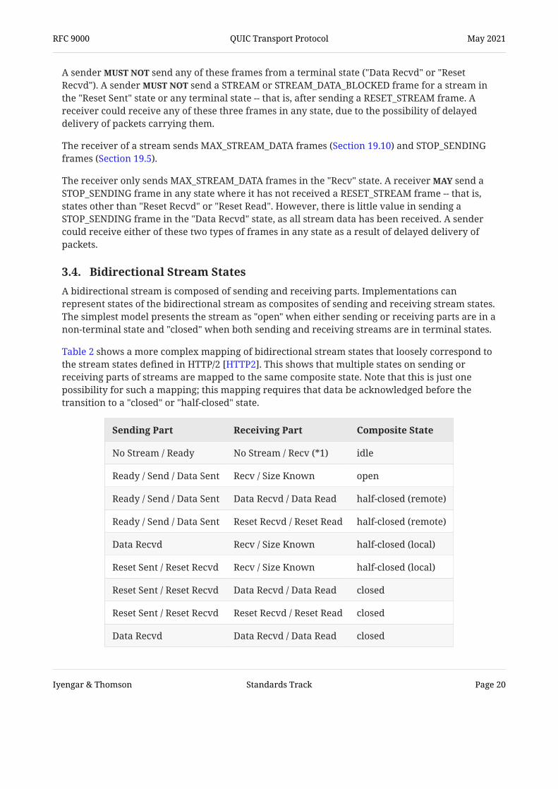
3.4. Bidirectional Stream States A bidirectional stream is composed of sending and receiving parts. Implementations canrepresent states of the bidirectional stream as composites of sending and receiving stream states.The simplest model presents the stream as "open" when either sending or receiving parts are in anon-terminal state and "closed" when both sending and receiving streams are in terminal states.
Table 2 shows a more complex mapping of bidirectional stream states that loosely correspond tothe stream states defined in HTTP/2 . This shows that multiple states on sending orreceiving parts of streams are mapped to the same composite state. Note that this is just onepossibility for such a mapping; this mapping requires that data be acknowledged before thetransition to a "closed" or "half-closed" state.
[HTTP2]
Sending Part Receiving Part Composite State
No Stream / Ready No Stream / Recv (*1) idle
Ready / Send / Data Sent Recv / Size Known open
Ready / Send / Data Sent Data Recvd / Data Read half-closed (remote)
Ready / Send / Data Sent Reset Recvd / Reset Read half-closed (remote)
Data Recvd Recv / Size Known half-closed (local)
Reset Sent / Reset Recvd Recv / Size Known half-closed (local)
Reset Sent / Reset Recvd Data Recvd / Data Read closed
Reset Sent / Reset Recvd Reset Recvd / Reset Read closed
Data Recvd Data Recvd / Data Read closed
RFC 9000 QUIC Transport Protocol May 2021
Iyengar & Thomson Standards Track Page 20

Note (*1): A stream is considered "idle" if it has not yet been created or if thereceiving part of the stream is in the "Recv" state without yet having received anyframes.
Sending Part Receiving Part Composite State
Data Recvd Reset Recvd / Reset Read closed
Table 2: Possible Mapping of Stream States to HTTP/2
3.5. Solicited State Transitions If an application is no longer interested in the data it is receiving on a stream, it can abortreading the stream and specify an application error code.
If the stream is in the "Recv" or "Size Known" state, the transport signal this by sending aSTOP_SENDING frame to prompt closure of the stream in the opposite direction. This typicallyindicates that the receiving application is no longer reading data it receives from the stream, butit is not a guarantee that incoming data will be ignored.
STREAM frames received after sending a STOP_SENDING frame are still counted towardconnection and stream flow control, even though these frames can be discarded upon receipt.
A STOP_SENDING frame requests that the receiving endpoint send a RESET_STREAM frame. Anendpoint that receives a STOP_SENDING frame send a RESET_STREAM frame if the streamis in the "Ready" or "Send" state. If the stream is in the "Data Sent" state, the endpoint defersending the RESET_STREAM frame until the packets containing outstanding data areacknowledged or declared lost. If any outstanding data is declared lost, the endpoint send a RESET_STREAM frame instead of retransmitting the data.
An endpoint copy the error code from the STOP_SENDING frame to the RESET_STREAMframe it sends, but it can use any application error code. An endpoint that sends aSTOP_SENDING frame ignore the error code in any RESET_STREAM frames subsequentlyreceived for that stream.
STOP_SENDING only be sent for a stream that has not been reset by the peer.STOP_SENDING is most useful for streams in the "Recv" or "Size Known" state.
An endpoint is expected to send another STOP_SENDING frame if a packet containing a previousSTOP_SENDING is lost. However, once either all stream data or a RESET_STREAM frame has beenreceived for the stream -- that is, the stream is in any state other than "Recv" or "Size Known" --sending a STOP_SENDING frame is unnecessary.
An endpoint that wishes to terminate both directions of a bidirectional stream can terminate onedirection by sending a RESET_STREAM frame, and it can encourage prompt termination in theopposite direction by sending a STOP_SENDING frame.
SHOULD
MUSTMAY
SHOULD
SHOULD
MAY
SHOULD
RFC 9000 QUIC Transport Protocol May 2021
Iyengar & Thomson Standards Track Page 21

4. Flow Control Receivers need to limit the amount of data that they are required to buffer, in order to prevent afast sender from overwhelming them or a malicious sender from consuming a large amount ofmemory. To enable a receiver to limit memory commitments for a connection, streams are flowcontrolled both individually and across a connection as a whole. A QUIC receiver controls themaximum amount of data the sender can send on a stream as well as across all streams at anytime, as described in Sections 4.1 and 4.2.
Similarly, to limit concurrency within a connection, a QUIC endpoint controls the maximumcumulative number of streams that its peer can initiate, as described in Section 4.6.
Data sent in CRYPTO frames is not flow controlled in the same way as stream data. QUIC relies onthe cryptographic protocol implementation to avoid excessive buffering of data; see .To avoid excessive buffering at multiple layers, QUIC implementations provide aninterface for the cryptographic protocol implementation to communicate its buffering limits.
[QUIC-TLS]SHOULD
4.1. Data Flow Control QUIC employs a limit-based flow control scheme where a receiver advertises the limit of totalbytes it is prepared to receive on a given stream or for the entire connection. This leads to twolevels of data flow control in QUIC:
Stream flow control, which prevents a single stream from consuming the entire receivebuffer for a connection by limiting the amount of data that can be sent on each stream. Connection flow control, which prevents senders from exceeding a receiver's buffer capacityfor the connection by limiting the total bytes of stream data sent in STREAM frames on allstreams.
Senders send data in excess of either limit.
A receiver sets initial limits for all streams through transport parameters during the handshake(Section 7.4). Subsequently, a receiver sends MAX_STREAM_DATA frames (Section 19.10) orMAX_DATA frames (Section 19.9) to the sender to advertise larger limits.
A receiver can advertise a larger limit for a stream by sending a MAX_STREAM_DATA frame withthe corresponding stream ID. A MAX_STREAM_DATA frame indicates the maximum absolute byteoffset of a stream. A receiver could determine the flow control offset to be advertised based onthe current offset of data consumed on that stream.
A receiver can advertise a larger limit for a connection by sending a MAX_DATA frame, whichindicates the maximum of the sum of the absolute byte offsets of all streams. A receivermaintains a cumulative sum of bytes received on all streams, which is used to check forviolations of the advertised connection or stream data limits. A receiver could determine themaximum data limit to be advertised based on the sum of bytes consumed on all streams.
•
•
MUST NOT
RFC 9000 QUIC Transport Protocol May 2021
Iyengar & Thomson Standards Track Page 22

Once a receiver advertises a limit for the connection or a stream, it is not an error to advertise asmaller limit, but the smaller limit has no effect.
A receiver close the connection with an error of type FLOW_CONTROL_ERROR if thesender violates the advertised connection or stream data limits; see Section 11 for details onerror handling.
A sender ignore any MAX_STREAM_DATA or MAX_DATA frames that do not increase flowcontrol limits.
If a sender has sent data up to the limit, it will be unable to send new data and is consideredblocked. A sender send a STREAM_DATA_BLOCKED or DATA_BLOCKED frame to indicateto the receiver that it has data to write but is blocked by flow control limits. If a sender is blockedfor a period longer than the idle timeout (Section 10.1), the receiver might close the connectioneven when the sender has data that is available for transmission. To keep the connection fromclosing, a sender that is flow control limited periodically send aSTREAM_DATA_BLOCKED or DATA_BLOCKED frame when it has no ack-eliciting packets in flight.
MUST
MUST
SHOULD
SHOULD
4.2. Increasing Flow Control Limits Implementations decide when and how much credit to advertise in MAX_STREAM_DATA andMAX_DATA frames, but this section offers a few considerations.
To avoid blocking a sender, a receiver send a MAX_STREAM_DATA or MAX_DATA framemultiple times within a round trip or send it early enough to allow time for loss of the frame andsubsequent recovery.
Control frames contribute to connection overhead. Therefore, frequently sendingMAX_STREAM_DATA and MAX_DATA frames with small changes is undesirable. On the otherhand, if updates are less frequent, larger increments to limits are necessary to avoid blocking asender, requiring larger resource commitments at the receiver. There is a trade-off betweenresource commitment and overhead when determining how large a limit is advertised.
A receiver can use an autotuning mechanism to tune the frequency and amount of advertisedadditional credit based on a round-trip time estimate and the rate at which the receivingapplication consumes data, similar to common TCP implementations. As an optimization, anendpoint could send frames related to flow control only when there are other frames to send,ensuring that flow control does not cause extra packets to be sent.
A blocked sender is not required to send STREAM_DATA_BLOCKED or DATA_BLOCKED frames.Therefore, a receiver wait for a STREAM_DATA_BLOCKED or DATA_BLOCKED framebefore sending a MAX_STREAM_DATA or MAX_DATA frame; doing so could result in the senderbeing blocked for the rest of the connection. Even if the sender sends these frames, waiting forthem will result in the sender being blocked for at least an entire round trip.
When a sender receives credit after being blocked, it might be able to send a large amount ofdata in response, resulting in short-term congestion; see for adiscussion of how a sender can avoid this congestion.
MAY
MUST NOT
Section 7.7 of [QUIC-RECOVERY]
RFC 9000 QUIC Transport Protocol May 2021
Iyengar & Thomson Standards Track Page 23
4.3. Flow Control Performance If an endpoint cannot ensure that its peer always has available flow control credit that is greaterthan the peer's bandwidth-delay product on this connection, its receive throughput will belimited by flow control.
Packet loss can cause gaps in the receive buffer, preventing the application from consuming dataand freeing up receive buffer space.
Sending timely updates of flow control limits can improve performance. Sending packets only toprovide flow control updates can increase network load and adversely affect performance.Sending flow control updates along with other frames, such as ACK frames, reduces the cost ofthose updates.
4.4. Handling Stream Cancellation Endpoints need to eventually agree on the amount of flow control credit that has been consumedon every stream, to be able to account for all bytes for connection-level flow control.
On receipt of a RESET_STREAM frame, an endpoint will tear down state for the matching streamand ignore further data arriving on that stream.
RESET_STREAM terminates one direction of a stream abruptly. For a bidirectional stream,RESET_STREAM has no effect on data flow in the opposite direction. Both endpoints maintain flow control state for the stream in the unterminated direction until that directionenters a terminal state.
MUST
4.5. Stream Final Size The final size is the amount of flow control credit that is consumed by a stream. Assuming thatevery contiguous byte on the stream was sent once, the final size is the number of bytes sent.More generally, this is one higher than the offset of the byte with the largest offset sent on thestream, or zero if no bytes were sent.
A sender always communicates the final size of a stream to the receiver reliably, no matter howthe stream is terminated. The final size is the sum of the Offset and Length fields of a STREAMframe with a FIN flag, noting that these fields might be implicit. Alternatively, the Final Size fieldof a RESET_STREAM frame carries this value. This guarantees that both endpoints agree on howmuch flow control credit was consumed by the sender on that stream.
An endpoint will know the final size for a stream when the receiving part of the stream entersthe "Size Known" or "Reset Recvd" state (Section 3). The receiver use the final size of thestream to account for all bytes sent on the stream in its connection-level flow controller.
An endpoint send data on a stream at or beyond the final size.
MUST
MUST NOT
RFC 9000 QUIC Transport Protocol May 2021
Iyengar & Thomson Standards Track Page 24

Once a final size for a stream is known, it cannot change. If a RESET_STREAM or STREAM frameis received indicating a change in the final size for the stream, an endpoint respond withan error of type FINAL_SIZE_ERROR; see Section 11 for details on error handling. A receiver
treat receipt of data at or beyond the final size as an error of type FINAL_SIZE_ERROR,even after a stream is closed. Generating these errors is not mandatory, because requiring thatan endpoint generate these errors also means that the endpoint needs to maintain the final sizestate for closed streams, which could mean a significant state commitment.
SHOULD
SHOULD
4.6. Controlling Concurrency An endpoint limits the cumulative number of incoming streams a peer can open. Only streamswith a stream ID less than (max_streams * 4 + first_stream_id_of_type) can be opened;see Table 1. Initial limits are set in the transport parameters; see Section 18.2. Subsequent limitsare advertised using MAX_STREAMS frames; see Section 19.11. Separate limits apply tounidirectional and bidirectional streams.
If a max_streams transport parameter or a MAX_STREAMS frame is received with a value greaterthan 260, this would allow a maximum stream ID that cannot be expressed as a variable-lengthinteger; see Section 16. If either is received, the connection be closed immediately with aconnection error of type TRANSPORT_PARAMETER_ERROR if the offending value was received ina transport parameter or of type FRAME_ENCODING_ERROR if it was received in a frame; see Section 10.2.
Endpoints exceed the limit set by their peer. An endpoint that receives a frame with astream ID exceeding the limit it has sent treat this as a connection error of typeSTREAM_LIMIT_ERROR; see Section 11 for details on error handling.
Once a receiver advertises a stream limit using the MAX_STREAMS frame, advertising a smallerlimit has no effect. MAX_STREAMS frames that do not increase the stream limit be ignored.
As with stream and connection flow control, this document leaves implementations to decidewhen and how many streams should be advertised to a peer via MAX_STREAMS.Implementations might choose to increase limits as streams are closed, to keep the number ofstreams available to peers roughly consistent.
An endpoint that is unable to open a new stream due to the peer's limits send aSTREAMS_BLOCKED frame (Section 19.14). This signal is considered useful for debugging. Anendpoint wait to receive this signal before advertising additional credit, since doing sowill mean that the peer will be blocked for at least an entire round trip, and potentiallyindefinitely if the peer chooses not to send STREAMS_BLOCKED frames.
MUST
MUST NOTMUST
MUST
SHOULD
MUST NOT
5. Connections A QUIC connection is shared state between a client and a server.
RFC 9000 QUIC Transport Protocol May 2021
Iyengar & Thomson Standards Track Page 25

Each connection starts with a handshake phase, during which the two endpoints establish ashared secret using the cryptographic handshake protocol and negotiate theapplication protocol. The handshake (Section 7) confirms that both endpoints are willing tocommunicate (Section 8.1) and establishes parameters for the connection (Section 7.4).
An application protocol can use the connection during the handshake phase with somelimitations. 0-RTT allows application data to be sent by a client before receiving a response fromthe server. However, 0-RTT provides no protection against replay attacks; see
. A server can also send application data to a client before it receives the finalcryptographic handshake messages that allow it to confirm the identity and liveness of the client.These capabilities allow an application protocol to offer the option of trading some securityguarantees for reduced latency.
The use of connection IDs (Section 5.1) allows connections to migrate to a new network path,both as a direct choice of an endpoint and when forced by a change in a middlebox. Section 9describes mitigations for the security and privacy issues associated with migration.
For connections that are no longer needed or desired, there are several ways for a client andserver to terminate a connection, as described in Section 10.
[QUIC-TLS]
Section 9.2 of[QUIC-TLS]
5.1. Connection ID Each connection possesses a set of connection identifiers, or connection IDs, each of which canidentify the connection. Connection IDs are independently selected by endpoints; each endpointselects the connection IDs that its peer uses.
The primary function of a connection ID is to ensure that changes in addressing at lowerprotocol layers (UDP, IP) do not cause packets for a QUIC connection to be delivered to the wrongendpoint. Each endpoint selects connection IDs using an implementation-specific (and perhapsdeployment-specific) method that will allow packets with that connection ID to be routed back tothe endpoint and to be identified by the endpoint upon receipt.
Multiple connection IDs are used so that endpoints can send packets that cannot be identified byan observer as being for the same connection without cooperation from an endpoint; see Section9.5.
Connection IDs contain any information that can be used by an external observer(that is, one that does not cooperate with the issuer) to correlate them with other connection IDsfor the same connection. As a trivial example, this means the same connection ID beissued more than once on the same connection.
Packets with long headers include Source Connection ID and Destination Connection ID fields.These fields are used to set the connection IDs for new connections; see Section 7.2 for details.
Packets with short headers (Section 17.3) only include the Destination Connection ID and omitthe explicit length. The length of the Destination Connection ID field is expected to be known toendpoints. Endpoints using a load balancer that routes based on connection ID could agree with
MUST NOT
MUST NOT
RFC 9000 QUIC Transport Protocol May 2021
Iyengar & Thomson Standards Track Page 26

the load balancer on a fixed length for connection IDs or agree on an encoding scheme. A fixedportion could encode an explicit length, which allows the entire connection ID to vary in lengthand still be used by the load balancer.
A Version Negotiation (Section 17.2.1) packet echoes the connection IDs selected by the client,both to ensure correct routing toward the client and to demonstrate that the packet is inresponse to a packet sent by the client.
A zero-length connection ID can be used when a connection ID is not needed to route to thecorrect endpoint. However, multiplexing connections on the same local IP address and portwhile using zero-length connection IDs will cause failures in the presence of peer connectionmigration, NAT rebinding, and client port reuse. An endpoint use the same IP addressand port for multiple concurrent connections with zero-length connection IDs, unless it is certainthat those protocol features are not in use.
When an endpoint uses a non-zero-length connection ID, it needs to ensure that the peer has asupply of connection IDs from which to choose for packets sent to the endpoint. Theseconnection IDs are supplied by the endpoint using the NEW_CONNECTION_ID frame (Section19.15).
MUST NOT
5.1.1. Issuing Connection IDs
Each connection ID has an associated sequence number to assist in detecting whenNEW_CONNECTION_ID or RETIRE_CONNECTION_ID frames refer to the same value. The initialconnection ID issued by an endpoint is sent in the Source Connection ID field of the long packetheader (Section 17.2) during the handshake. The sequence number of the initial connection ID is0. If the preferred_address transport parameter is sent, the sequence number of the suppliedconnection ID is 1.
Additional connection IDs are communicated to the peer using NEW_CONNECTION_ID frames(Section 19.15). The sequence number on each newly issued connection ID increase by 1.The connection ID that a client selects for the first Destination Connection ID field it sends andany connection ID provided by a Retry packet are not assigned sequence numbers.
When an endpoint issues a connection ID, it accept packets that carry this connection IDfor the duration of the connection or until its peer invalidates the connection ID via aRETIRE_CONNECTION_ID frame (Section 19.16). Connection IDs that are issued and not retiredare considered active; any active connection ID is valid for use with the current connection atany time, in any packet type. This includes the connection ID issued by the server via thepreferred_address transport parameter.
An endpoint ensure that its peer has a sufficient number of available and unusedconnection IDs. Endpoints advertise the number of active connection IDs they are willing tomaintain using the active_connection_id_limit transport parameter. An endpoint provide more connection IDs than the peer's limit. An endpoint send connection IDs thattemporarily exceed a peer's limit if the NEW_CONNECTION_ID frame also requires theretirement of any excess, by including a sufficiently large value in the Retire Prior To field.
MUST
MUST
SHOULD
MUST NOTMAY
RFC 9000 QUIC Transport Protocol May 2021
Iyengar & Thomson Standards Track Page 27

A NEW_CONNECTION_ID frame might cause an endpoint to add some active connection IDs andretire others based on the value of the Retire Prior To field. After processing aNEW_CONNECTION_ID frame and adding and retiring active connection IDs, if the number ofactive connection IDs exceeds the value advertised in its active_connection_id_limit transportparameter, an endpoint close the connection with an error of typeCONNECTION_ID_LIMIT_ERROR.
An endpoint supply a new connection ID when the peer retires a connection ID. If anendpoint provided fewer connection IDs than the peer's active_connection_id_limit, it supply a new connection ID when it receives a packet with a previously unused connection ID.An endpoint limit the total number of connection IDs issued for each connection to avoidthe risk of running out of connection IDs; see Section 10.3.2. An endpoint also limit theissuance of connection IDs to reduce the amount of per-path state it maintains, such as pathvalidation status, as its peer might interact with it over as many paths as there are issuedconnection IDs.
An endpoint that initiates migration and requires non-zero-length connection IDs ensure that the pool of connection IDs available to its peer allows the peer to use a newconnection ID on migration, as the peer will be unable to respond if the pool is exhausted.
An endpoint that selects a zero-length connection ID during the handshake cannot issue a newconnection ID. A zero-length Destination Connection ID field is used in all packets sent towardsuch an endpoint over any network path.
MUST
SHOULDMAY
MAYMAY
SHOULD
5.1.2. Consuming and Retiring Connection IDs
An endpoint can change the connection ID it uses for a peer to another available one at any timeduring the connection. An endpoint consumes connection IDs in response to a migrating peer;see Section 9.5 for more details.
An endpoint maintains a set of connection IDs received from its peer, any of which it can usewhen sending packets. When the endpoint wishes to remove a connection ID from use, it sends aRETIRE_CONNECTION_ID frame to its peer. Sending a RETIRE_CONNECTION_ID frame indicatesthat the connection ID will not be used again and requests that the peer replace it with a newconnection ID using a NEW_CONNECTION_ID frame.
As discussed in Section 9.5, endpoints limit the use of a connection ID to packets sent from asingle local address to a single destination address. Endpoints retire connection IDswhen they are no longer actively using either the local or destination address for which theconnection ID was used.
An endpoint might need to stop accepting previously issued connection IDs in certaincircumstances. Such an endpoint can cause its peer to retire connection IDs by sending aNEW_CONNECTION_ID frame with an increased Retire Prior To field. The endpoint continue to accept the previously issued connection IDs until they are retired by the peer. If theendpoint can no longer process the indicated connection IDs, it close the connection.
SHOULD
SHOULD
MAY
RFC 9000 QUIC Transport Protocol May 2021
Iyengar & Thomson Standards Track Page 28

Upon receipt of an increased Retire Prior To field, the peer stop using the correspondingconnection IDs and retire them with RETIRE_CONNECTION_ID frames before adding the newlyprovided connection ID to the set of active connection IDs. This ordering allows an endpoint toreplace all active connection IDs without the possibility of a peer having no available connectionIDs and without exceeding the limit the peer sets in the active_connection_id_limit transportparameter; see Section 18.2. Failure to cease using the connection IDs when requested can resultin connection failures, as the issuing endpoint might be unable to continue using the connectionIDs with the active connection.
An endpoint limit the number of connection IDs it has retired locally for whichRETIRE_CONNECTION_ID frames have not yet been acknowledged. An endpoint allowfor sending and tracking a number of RETIRE_CONNECTION_ID frames of at least twice the valueof the active_connection_id_limit transport parameter. An endpoint forget aconnection ID without retiring it, though it choose to treat having connection IDs in need ofretirement that exceed this limit as a connection error of type CONNECTION_ID_LIMIT_ERROR.
Endpoints issue updates of the Retire Prior To field before receivingRETIRE_CONNECTION_ID frames that retire all connection IDs indicated by the previous RetirePrior To value.
MUST
SHOULDSHOULD
MUST NOTMAY
SHOULD NOT
5.2. Matching Packets to Connections Incoming packets are classified on receipt. Packets can either be associated with an existingconnection or -- for servers -- potentially create a new connection.
Endpoints try to associate a packet with an existing connection. If the packet has a non-zero-length Destination Connection ID corresponding to an existing connection, QUIC processes thatpacket accordingly. Note that more than one connection ID can be associated with a connection;see Section 5.1.
If the Destination Connection ID is zero length and the addressing information in the packetmatches the addressing information the endpoint uses to identify a connection with a zero-length connection ID, QUIC processes the packet as part of that connection. An endpoint can usejust destination IP and port or both source and destination addresses for identification, thoughthis makes connections fragile as described in Section 5.1.
Endpoints can send a Stateless Reset (Section 10.3) for any packets that cannot be attributed to anexisting connection. A Stateless Reset allows a peer to more quickly identify when a connectionbecomes unusable.
Packets that are matched to an existing connection are discarded if the packets are inconsistentwith the state of that connection. For example, packets are discarded if they indicate a differentprotocol version than that of the connection or if the removal of packet protection isunsuccessful once the expected keys are available.
RFC 9000 QUIC Transport Protocol May 2021
Iyengar & Thomson Standards Track Page 29

Invalid packets that lack strong integrity protection, such as Initial, Retry, or Version Negotiation, be discarded. An endpoint generate a connection error if processing the contents of
these packets prior to discovering an error, or fully revert any changes made during thatprocessing.
MAY MUST
5.2.1. Client Packet Handling
Valid packets sent to clients always include a Destination Connection ID that matches a value theclient selects. Clients that choose to receive zero-length connection IDs can use the local addressand port to identify a connection. Packets that do not match an existing connection -- based onDestination Connection ID or, if this value is zero length, local IP address and port -- arediscarded.
Due to packet reordering or loss, a client might receive packets for a connection that areencrypted with a key it has not yet computed. The client drop these packets, or it bufferthem in anticipation of later packets that allow it to compute the key.
If a client receives a packet that uses a different version than it initially selected, it discardthat packet.
MAY MAY
MUST
5.2.2. Server Packet Handling
If a server receives a packet that indicates an unsupported version and if the packet is largeenough to initiate a new connection for any supported version, the server send aVersion Negotiation packet as described in Section 6.1. A server limit the number of packetsto which it responds with a Version Negotiation packet. Servers drop smaller packets thatspecify unsupported versions.
The first packet for an unsupported version can use different semantics and encodings for anyversion-specific field. In particular, different packet protection keys might be used for differentversions. Servers that do not support a particular version are unlikely to be able to decrypt thepayload of the packet or properly interpret the result. Servers respond with a VersionNegotiation packet, provided that the datagram is sufficiently long.
Packets with a supported version, or no Version field, are matched to a connection using theconnection ID or -- for packets with zero-length connection IDs -- the local address and port.These packets are processed using the selected connection; otherwise, the server continues asdescribed below.
If the packet is an Initial packet fully conforming with the specification, the server proceeds withthe handshake (Section 7). This commits the server to the version that the client selected.
If a server refuses to accept a new connection, it send an Initial packet containing aCONNECTION_CLOSE frame with error code CONNECTION_REFUSED.
If the packet is a 0-RTT packet, the server buffer a limited number of these packets inanticipation of a late-arriving Initial packet. Clients are not able to send Handshake packets priorto receiving a server response, so servers ignore any such packets.
SHOULDMAYMUST
SHOULD
SHOULD
MAY
SHOULD
RFC 9000 QUIC Transport Protocol May 2021
Iyengar & Thomson Standards Track Page 30

Servers drop incoming packets under all other circumstances.MUST
5.2.3. Considerations for Simple Load Balancers
A server deployment could load-balance among servers using only source and destination IPaddresses and ports. Changes to the client's IP address or port could result in packets beingforwarded to the wrong server. Such a server deployment could use one of the followingmethods for connection continuity when a client's address changes.
Servers could use an out-of-band mechanism to forward packets to the correct server basedon connection ID. If servers can use a dedicated server IP address or port, other than the one that the clientinitially connects to, they could use the preferred_address transport parameter to requestthat clients move connections to that dedicated address. Note that clients could choose not touse the preferred address.
A server in a deployment that does not implement a solution to maintain connection continuitywhen the client address changes indicate that migration is not supported by using thedisable_active_migration transport parameter. The disable_active_migration transportparameter does not prohibit connection migration after a client has acted on a preferred_addresstransport parameter.
Server deployments that use this simple form of load balancing avoid the creation of astateless reset oracle; see Section 21.11.
•
•
SHOULD
MUST
5.3. Operations on Connections This document does not define an API for QUIC; it instead defines a set of functions for QUICconnections that application protocols can rely upon. An application protocol can assume that animplementation of QUIC provides an interface that includes the operations described in thissection. An implementation designed for use with a specific application protocol might provideonly those operations that are used by that protocol.
When implementing the client role, an application protocol can:
open a connection, which begins the exchange described in Section 7; enable Early Data when available; and be informed when Early Data has been accepted or rejected by a server.
When implementing the server role, an application protocol can:
listen for incoming connections, which prepares for the exchange described in Section 7; if Early Data is supported, embed application-controlled data in the TLS resumption ticketsent to the client; and if Early Data is supported, retrieve application-controlled data from the client's resumptionticket and accept or reject Early Data based on that information.
• • •
• •
•
RFC 9000 QUIC Transport Protocol May 2021
Iyengar & Thomson Standards Track Page 31

In either role, an application protocol can:
configure minimum values for the initial number of permitted streams of each type, ascommunicated in the transport parameters (Section 7.4); control resource allocation for receive buffers by setting flow control limits both for streamsand for the connection; identify whether the handshake has completed successfully or is still ongoing; keep a connection from silently closing, by either generating PING frames (Section 19.2) orrequesting that the transport send additional frames before the idle timeout expires (Section10.1); and immediately close (Section 10.2) the connection.
•
•
• •
•
6. Version Negotiation Version negotiation allows a server to indicate that it does not support the version the clientused. A server sends a Version Negotiation packet in response to each packet that might initiate anew connection; see Section 5.2 for details.
The size of the first packet sent by a client will determine whether a server sends a VersionNegotiation packet. Clients that support multiple QUIC versions ensure that the first UDPdatagram they send is sized to the largest of the minimum datagram sizes from all versions theysupport, using PADDING frames (Section 19.1) as necessary. This ensures that the server respondsif there is a mutually supported version. A server might not send a Version Negotiation packet ifthe datagram it receives is smaller than the minimum size specified in a different version; see Section 14.1.
SHOULD
6.1. Sending Version Negotiation Packets If the version selected by the client is not acceptable to the server, the server responds with aVersion Negotiation packet; see Section 17.2.1. This includes a list of versions that the server willaccept. An endpoint send a Version Negotiation packet in response to receiving aVersion Negotiation packet.
This system allows a server to process packets with unsupported versions without retainingstate. Though either the Initial packet or the Version Negotiation packet that is sent in responsecould be lost, the client will send new packets until it successfully receives a response or itabandons the connection attempt.
A server limit the number of Version Negotiation packets it sends. For instance, a server thatis able to recognize packets as 0-RTT might choose not to send Version Negotiation packets inresponse to 0-RTT packets with the expectation that it will eventually receive an Initial packet.
MUST NOT
MAY
RFC 9000 QUIC Transport Protocol May 2021
Iyengar & Thomson Standards Track Page 32

6.2. Handling Version Negotiation Packets Version Negotiation packets are designed to allow for functionality to be defined in the futurethat allows QUIC to negotiate the version of QUIC to use for a connection. Future Standards Trackspecifications might change how implementations that support multiple versions of QUIC reactto Version Negotiation packets received in response to an attempt to establish a connection usingthis version.
A client that supports only this version of QUIC abandon the current connection attempt ifit receives a Version Negotiation packet, with the following two exceptions. A client discardany Version Negotiation packet if it has received and successfully processed any other packet,including an earlier Version Negotiation packet. A client discard a Version Negotiationpacket that lists the QUIC version selected by the client.
How to perform version negotiation is left as future work defined by future Standards Trackspecifications. In particular, that future work will ensure robustness against version downgradeattacks; see Section 21.12.
MUSTMUST
MUST
6.3. Using Reserved Versions For a server to use a new version in the future, clients need to correctly handle unsupportedversions. Some version numbers (0x?a?a?a?a, as defined in Section 15) are reserved for inclusionin fields that contain version numbers.
Endpoints add reserved versions to any field where unknown or unsupported versions areignored to test that a peer correctly ignores the value. For instance, an endpoint could include areserved version in a Version Negotiation packet; see Section 17.2.1. Endpoints send packetswith a reserved version to test that a peer correctly discards the packet.
MAY
MAY
7. Cryptographic and Transport Handshake QUIC relies on a combined cryptographic and transport handshake to minimize connectionestablishment latency. QUIC uses the CRYPTO frame (Section 19.6) to transmit the cryptographichandshake. The version of QUIC defined in this document is identified as 0x00000001 and usesTLS as described in ; a different QUIC version could indicate that a differentcryptographic handshake protocol is in use.
QUIC provides reliable, ordered delivery of the cryptographic handshake data. QUIC packetprotection is used to encrypt as much of the handshake protocol as possible. The cryptographichandshake provide the following properties:
authenticated key exchange, wherea server is always authenticated, a client is optionally authenticated, every connection produces distinct and unrelated keys, and
[QUIC-TLS]
MUST
• ◦
◦
◦
RFC 9000 QUIC Transport Protocol May 2021
Iyengar & Thomson Standards Track Page 33

keying material is usable for packet protection for both 0-RTT and 1-RTT packets.
authenticated exchange of values for transport parameters of both endpoints, andconfidentiality protection for server transport parameters (see Section 7.4). authenticated negotiation of an application protocol (TLS uses Application-Layer ProtocolNegotiation (ALPN) for this purpose).
The CRYPTO frame can be sent in different packet number spaces (Section 12.3). The offsets usedby CRYPTO frames to ensure ordered delivery of cryptographic handshake data start from zeroin each packet number space.
Figure 4 shows a simplified handshake and the exchange of packets and frames that are used toadvance the handshake. Exchange of application data during the handshake is enabled wherepossible, shown with an asterisk ("*"). Once the handshake is complete, endpoints are able toexchange application data freely.
Endpoints can use packets sent during the handshake to test for Explicit Congestion Notification(ECN) support; see Section 13.4. An endpoint validates support for ECN by observing whether theACK frames acknowledging the first packets it sends carry ECN counts, as described in Section13.4.2.
Endpoints explicitly negotiate an application protocol. This avoids situations where there isa disagreement about the protocol that is in use.
◦
•
• [ALPN]
Figure 4: Simplified QUIC Handshake
Client Server
Initial (CRYPTO)0-RTT (*) ----------> Initial (CRYPTO) Handshake (CRYPTO) <---------- 1-RTT (*)Handshake (CRYPTO)1-RTT (*) ----------> <---------- 1-RTT (HANDSHAKE_DONE)
1-RTT <=========> 1-RTT
MUST
7.1. Example Handshake Flows Details of how TLS is integrated with QUIC are provided in , but some examples areprovided here. An extension of this exchange to support client address validation is shown in Section 8.1.2.
Once any address validation exchanges are complete, the cryptographic handshake is used toagree on cryptographic keys. The cryptographic handshake is carried in Initial (Section 17.2.2)and Handshake (Section 17.2.4) packets.
[QUIC-TLS]
RFC 9000 QUIC Transport Protocol May 2021
Iyengar & Thomson Standards Track Page 34

Figure 5 provides an overview of the 1-RTT handshake. Each line shows a QUIC packet with thepacket type and packet number shown first, followed by the frames that are typically containedin those packets. For instance, the first packet is of type Initial, with packet number 0, andcontains a CRYPTO frame carrying the ClientHello.
Multiple QUIC packets -- even of different packet types -- can be coalesced into a single UDPdatagram; see Section 12.2. As a result, this handshake could consist of as few as four UDPdatagrams, or any number more (subject to limits inherent to the protocol, such as congestioncontrol and anti-amplification). For instance, the server's first flight contains Initial packets,Handshake packets, and "0.5-RTT data" in 1-RTT packets.
Figure 6 shows an example of a connection with a 0-RTT handshake and a single packet of 0-RTTdata. Note that as described in Section 12.3, the server acknowledges 0-RTT data in 1-RTT packets,and the client sends 1-RTT packets in the same packet number space.
Figure 5: Example 1-RTT Handshake
Client Server
Initial[0]: CRYPTO[CH] ->
Initial[0]: CRYPTO[SH] ACK[0] Handshake[0]: CRYPTO[EE, CERT, CV, FIN] <- 1-RTT[0]: STREAM[1, "..."]
Initial[1]: ACK[0]Handshake[0]: CRYPTO[FIN], ACK[0]1-RTT[0]: STREAM[0, "..."], ACK[0] ->
Handshake[1]: ACK[0] <- 1-RTT[1]: HANDSHAKE_DONE, STREAM[3, "..."], ACK[0]
Figure 6: Example 0-RTT Handshake
Client Server
Initial[0]: CRYPTO[CH]0-RTT[0]: STREAM[0, "..."] ->
Initial[0]: CRYPTO[SH] ACK[0] Handshake[0] CRYPTO[EE, FIN] <- 1-RTT[0]: STREAM[1, "..."] ACK[0]
Initial[1]: ACK[0]Handshake[0]: CRYPTO[FIN], ACK[0]1-RTT[1]: STREAM[0, "..."] ACK[0] ->
Handshake[1]: ACK[0] <- 1-RTT[1]: HANDSHAKE_DONE, STREAM[3, "..."], ACK[1]
RFC 9000 QUIC Transport Protocol May 2021
Iyengar & Thomson Standards Track Page 35

7.2. Negotiating Connection IDs A connection ID is used to ensure consistent routing of packets, as described in Section 5.1. Thelong header contains two connection IDs: the Destination Connection ID is chosen by therecipient of the packet and is used to provide consistent routing; the Source Connection ID isused to set the Destination Connection ID used by the peer.
During the handshake, packets with the long header (Section 17.2) are used to establish theconnection IDs used by both endpoints. Each endpoint uses the Source Connection ID field tospecify the connection ID that is used in the Destination Connection ID field of packets being sentto them. After processing the first Initial packet, each endpoint sets the Destination Connection IDfield in subsequent packets it sends to the value of the Source Connection ID field that it received.
When an Initial packet is sent by a client that has not previously received an Initial or Retrypacket from the server, the client populates the Destination Connection ID field with anunpredictable value. This Destination Connection ID be at least 8 bytes in length. Until apacket is received from the server, the client use the same Destination Connection ID valueon all packets in this connection.
The Destination Connection ID field from the first Initial packet sent by a client is used todetermine packet protection keys for Initial packets. These keys change after receiving a Retrypacket; see .
The client populates the Source Connection ID field with a value of its choosing and sets theSource Connection ID Length field to indicate the length.
0-RTT packets in the first flight use the same Destination Connection ID and Source Connection IDvalues as the client's first Initial packet.
Upon first receiving an Initial or Retry packet from the server, the client uses the SourceConnection ID supplied by the server as the Destination Connection ID for subsequent packets,including any 0-RTT packets. This means that a client might have to change the connection ID itsets in the Destination Connection ID field twice during connection establishment: once inresponse to a Retry packet and once in response to an Initial packet from the server. Once aclient has received a valid Initial packet from the server, it discard any subsequent packetit receives on that connection with a different Source Connection ID.
A client change the Destination Connection ID it uses for sending packets in response toonly the first received Initial or Retry packet. A server set the Destination Connection ID ituses for sending packets based on the first received Initial packet. Any further changes to theDestination Connection ID are only permitted if the values are taken fromNEW_CONNECTION_ID frames; if subsequent Initial packets include a different SourceConnection ID, they be discarded. This avoids unpredictable outcomes that mightotherwise result from stateless processing of multiple Initial packets with different SourceConnection IDs.
MUSTMUST
Section 5.2 of [QUIC-TLS]
MUST
MUSTMUST
MUST
RFC 9000 QUIC Transport Protocol May 2021
Iyengar & Thomson Standards Track Page 36

The Destination Connection ID that an endpoint sends can change over the lifetime of aconnection, especially in response to connection migration (Section 9); see Section 5.1.1 fordetails.
7.3. Authenticating Connection IDs The choice each endpoint makes about connection IDs during the handshake is authenticated byincluding all values in transport parameters; see Section 7.4. This ensures that all connection IDsused for the handshake are also authenticated by the cryptographic handshake.
Each endpoint includes the value of the Source Connection ID field from the first Initial packet itsent in the initial_source_connection_id transport parameter; see Section 18.2. A server includesthe Destination Connection ID field from the first Initial packet it received from the client in theoriginal_destination_connection_id transport parameter; if the server sent a Retry packet, thisrefers to the first Initial packet received before sending the Retry packet. If it sends a Retrypacket, a server also includes the Source Connection ID field from the Retry packet in theretry_source_connection_id transport parameter.
The values provided by a peer for these transport parameters match the values that anendpoint used in the Destination and Source Connection ID fields of Initial packets that it sent(and received, for servers). Endpoints validate that received transport parameters matchreceived connection ID values. Including connection ID values in transport parameters andverifying them ensures that an attacker cannot influence the choice of connection ID for asuccessful connection by injecting packets carrying attacker-chosen connection IDs during thehandshake.
An endpoint treat the absence of the initial_source_connection_id transport parameterfrom either endpoint or the absence of the original_destination_connection_id transportparameter from the server as a connection error of type TRANSPORT_PARAMETER_ERROR.
An endpoint treat the following as a connection error of typeTRANSPORT_PARAMETER_ERROR or PROTOCOL_VIOLATION:
absence of the retry_source_connection_id transport parameter from the server afterreceiving a Retry packet, presence of the retry_source_connection_id transport parameter when no Retry packet wasreceived, or a mismatch between values received from a peer in these transport parameters and thevalue sent in the corresponding Destination or Source Connection ID fields of Initial packets.
If a zero-length connection ID is selected, the corresponding transport parameter is includedwith a zero-length value.
Figure 7 shows the connection IDs (with DCID=Destination Connection ID, SCID=SourceConnection ID) that are used in a complete handshake. The exchange of Initial packets is shown,plus the later exchange of 1-RTT packets that includes the connection ID established during thehandshake.
MUST
MUST
MUST
MUST
•
•
•
RFC 9000 QUIC Transport Protocol May 2021
Iyengar & Thomson Standards Track Page 37

Figure 8 shows a similar handshake that includes a Retry packet.
In both cases (Figures 7 and 8), the client sets the value of the initial_source_connection_idtransport parameter to C1.
When the handshake does not include a Retry (Figure 7), the server setsoriginal_destination_connection_id to S1 (note that this value is chosen by the client) andinitial_source_connection_id to S3. In this case, the server does not include aretry_source_connection_id transport parameter.
When the handshake includes a Retry (Figure 8), the server setsoriginal_destination_connection_id to S1, retry_source_connection_id to S2, andinitial_source_connection_id to S3.
Figure 7: Use of Connection IDs in a Handshake
Client Server
Initial: DCID=S1, SCID=C1 -> <- Initial: DCID=C1, SCID=S3 ...1-RTT: DCID=S3 -> <- 1-RTT: DCID=C1
Figure 8: Use of Connection IDs in a Handshake with Retry
Client Server
Initial: DCID=S1, SCID=C1 -> <- Retry: DCID=C1, SCID=S2Initial: DCID=S2, SCID=C1 -> <- Initial: DCID=C1, SCID=S3 ...1-RTT: DCID=S3 -> <- 1-RTT: DCID=C1
7.4. Transport Parameters During connection establishment, both endpoints make authenticated declarations of theirtransport parameters. Endpoints are required to comply with the restrictions that eachparameter defines; the description of each parameter includes rules for its handling.
Transport parameters are declarations that are made unilaterally by each endpoint. Eachendpoint can choose values for transport parameters independent of the values chosen by itspeer.
The encoding of the transport parameters is detailed in Section 18.
RFC 9000 QUIC Transport Protocol May 2021
Iyengar & Thomson Standards Track Page 38

QUIC includes the encoded transport parameters in the cryptographic handshake. Once thehandshake completes, the transport parameters declared by the peer are available. Eachendpoint validates the values provided by its peer.
Definitions for each of the defined transport parameters are included in Section 18.2.
An endpoint treat receipt of a transport parameter with an invalid value as a connectionerror of type TRANSPORT_PARAMETER_ERROR.
An endpoint send a parameter more than once in a given transport parametersextension. An endpoint treat receipt of duplicate transport parameters as a connectionerror of type TRANSPORT_PARAMETER_ERROR.
Endpoints use transport parameters to authenticate the negotiation of connection IDs during thehandshake; see Section 7.3.
ALPN (see ) allows clients to offer multiple application protocols during connectionestablishment. The transport parameters that a client includes during the handshake apply to allapplication protocols that the client offers. Application protocols can recommend values fortransport parameters, such as the initial flow control limits. However, application protocols thatset constraints on values for transport parameters could make it impossible for a client to offermultiple application protocols if these constraints conflict.
MUST
MUST NOTSHOULD
[ALPN]
7.4.1. Values of Transport Parameters for 0-RTT
Using 0-RTT depends on both client and server using protocol parameters that were negotiatedfrom a previous connection. To enable 0-RTT, endpoints store the values of the server transportparameters with any session tickets it receives on the connection. Endpoints also store anyinformation required by the application protocol or cryptographic handshake; see
. The values of stored transport parameters are used when attempting 0-RTT using thesession tickets.
Remembered transport parameters apply to the new connection until the handshake completesand the client starts sending 1-RTT packets. Once the handshake completes, the client uses thetransport parameters established in the handshake. Not all transport parameters areremembered, as some do not apply to future connections or they have no effect on the use of 0-RTT.
The definition of a new transport parameter (Section 7.4.2) specify whether storing thetransport parameter for 0-RTT is mandatory, optional, or prohibited. A client need not store atransport parameter it cannot process.
A client use remembered values for the following parameters: ack_delay_exponent,max_ack_delay, initial_source_connection_id, original_destination_connection_id,preferred_address, retry_source_connection_id, and stateless_reset_token. The client usethe server's new values in the handshake instead; if the server does not provide new values, thedefault values are used.
Section 4.6 of[QUIC-TLS]
MUST
MUST NOT
MUST
RFC 9000 QUIC Transport Protocol May 2021
Iyengar & Thomson Standards Track Page 39

A client that attempts to send 0-RTT data remember all other transport parameters used bythe server that it is able to process. The server can remember these transport parameters or canstore an integrity-protected copy of the values in the ticket and recover the information whenaccepting 0-RTT data. A server uses the transport parameters in determining whether to accept 0-RTT data.
If 0-RTT data is accepted by the server, the server reduce any limits or alter any valuesthat might be violated by the client with its 0-RTT data. In particular, a server that accepts 0-RTTdata set values for the following parameters (Section 18.2) that are smaller than theremembered values of the parameters.
active_connection_id_limit initial_max_data initial_max_stream_data_bidi_local initial_max_stream_data_bidi_remote initial_max_stream_data_uni initial_max_streams_bidi initial_max_streams_uni
Omitting or setting a zero value for certain transport parameters can result in 0-RTT data beingenabled but not usable. The applicable subset of transport parameters that permit the sending ofapplication data be set to non-zero values for 0-RTT. This includes initial_max_data andeither (1) initial_max_streams_bidi and initial_max_stream_data_bidi_remote or (2)initial_max_streams_uni and initial_max_stream_data_uni.
A server might provide larger initial stream flow control limits for streams than the rememberedvalues that a client applies when sending 0-RTT. Once the handshake completes, the clientupdates the flow control limits on all sending streams using the updated values ofinitial_max_stream_data_bidi_remote and initial_max_stream_data_uni.
A server store and recover the previously sent values of the max_idle_timeout,max_udp_payload_size, and disable_active_migration parameters and reject 0-RTT if it selectssmaller values. Lowering the values of these parameters while also accepting 0-RTT data coulddegrade the performance of the connection. Specifically, lowering the max_udp_payload_sizecould result in dropped packets, leading to worse performance compared to rejecting 0-RTT dataoutright.
A server reject 0-RTT data if the restored values for transport parameters cannot besupported.
When sending frames in 0-RTT packets, a client only use remembered transportparameters; importantly, it use updated values that it learns from the server's updatedtransport parameters or from frames received in 1-RTT packets. Updated values of transportparameters from the handshake apply only to 1-RTT packets. For instance, flow control limits
MUST
MUST NOT
MUST NOT
• • • • • • •
SHOULD
MAY
MUST
MUSTMUST NOT
RFC 9000 QUIC Transport Protocol May 2021
Iyengar & Thomson Standards Track Page 40

from remembered transport parameters apply to all 0-RTT packets even if those values areincreased by the handshake or by frames sent in 1-RTT packets. A server treat the use ofupdated transport parameters in 0-RTT as a connection error of type PROTOCOL_VIOLATION.
MAY
7.4.2. New Transport Parameters
New transport parameters can be used to negotiate new protocol behavior. An endpoint ignore transport parameters that it does not support. The absence of a transport parametertherefore disables any optional protocol feature that is negotiated using the parameter. Asdescribed in Section 18.1, some identifiers are reserved in order to exercise this requirement.
A client that does not understand a transport parameter can discard it and attempt 0-RTT onsubsequent connections. However, if the client adds support for a discarded transportparameter, it risks violating the constraints that the transport parameter establishes if it attempts0-RTT. New transport parameters can avoid this problem by setting a default of the mostconservative value. Clients can avoid this problem by remembering all parameters, even thosenot currently supported.
New transport parameters can be registered according to the rules in Section 22.3.
MUST
7.5. Cryptographic Message Buffering Implementations need to maintain a buffer of CRYPTO data received out of order. Because thereis no flow control of CRYPTO frames, an endpoint could potentially force its peer to buffer anunbounded amount of data.
Implementations support buffering at least 4096 bytes of data received in out-of-orderCRYPTO frames. Endpoints choose to allow more data to be buffered during the handshake.A larger limit during the handshake could allow for larger keys or credentials to be exchanged.An endpoint's buffer size does not need to remain constant during the life of the connection.
Being unable to buffer CRYPTO frames during the handshake can lead to a connection failure. Ifan endpoint's buffer is exceeded during the handshake, it can expand its buffer temporarily tocomplete the handshake. If an endpoint does not expand its buffer, it close the connectionwith a CRYPTO_BUFFER_EXCEEDED error code.
Once the handshake completes, if an endpoint is unable to buffer all data in a CRYPTO frame, it discard that CRYPTO frame and all CRYPTO frames received in the future, or it close the
connection with a CRYPTO_BUFFER_EXCEEDED error code. Packets containing discarded CRYPTOframes be acknowledged because the packet has been received and processed by thetransport even though the CRYPTO frame was discarded.
MUSTMAY
MUST
MAY MAY
MUST
RFC 9000 QUIC Transport Protocol May 2021
Iyengar & Thomson Standards Track Page 41

8. Address Validation Address validation ensures that an endpoint cannot be used for a traffic amplification attack. Insuch an attack, a packet is sent to a server with spoofed source address information thatidentifies a victim. If a server generates more or larger packets in response to that packet, theattacker can use the server to send more data toward the victim than it would be able to send onits own.
The primary defense against amplification attacks is verifying that a peer is able to receivepackets at the transport address that it claims. Therefore, after receiving packets from an addressthat is not yet validated, an endpoint limit the amount of data it sends to the unvalidatedaddress to three times the amount of data received from that address. This limit on the size ofresponses is known as the anti-amplification limit.
Address validation is performed both during connection establishment (see Section 8.1) andduring connection migration (see Section 8.2).
MUST
8.1. Address Validation during Connection Establishment Connection establishment implicitly provides address validation for both endpoints. Inparticular, receipt of a packet protected with Handshake keys confirms that the peer successfullyprocessed an Initial packet. Once an endpoint has successfully processed a Handshake packetfrom the peer, it can consider the peer address to have been validated.
Additionally, an endpoint consider the peer address validated if the peer uses a connectionID chosen by the endpoint and the connection ID contains at least 64 bits of entropy.
For the client, the value of the Destination Connection ID field in its first Initial packet allows it tovalidate the server address as a part of successfully processing any packet. Initial packets fromthe server are protected with keys that are derived from this value (see
). Alternatively, the value is echoed by the server in Version Negotiation packets (Section 6)or included in the Integrity Tag in Retry packets ( ).
Prior to validating the client address, servers send more than three times as manybytes as the number of bytes they have received. This limits the magnitude of any amplificationattack that can be mounted using spoofed source addresses. For the purposes of avoidingamplification prior to address validation, servers count all of the payload bytes received indatagrams that are uniquely attributed to a single connection. This includes datagrams thatcontain packets that are successfully processed and datagrams that contain packets that are alldiscarded.
Clients ensure that UDP datagrams containing Initial packets have UDP payloads of at least1200 bytes, adding PADDING frames as necessary. A client that sends padded datagrams allowsthe server to send more data prior to completing address validation.
MAY
Section 5.2 of [QUIC-TLS]
Section 5.8 of [QUIC-TLS]
MUST NOT
MUST
MUST
RFC 9000 QUIC Transport Protocol May 2021
Iyengar & Thomson Standards Track Page 42

Loss of an Initial or Handshake packet from the server can cause a deadlock if the client does notsend additional Initial or Handshake packets. A deadlock could occur when the server reaches itsanti-amplification limit and the client has received acknowledgments for all the data it has sent.In this case, when the client has no reason to send additional packets, the server will be unable tosend more data because it has not validated the client's address. To prevent this deadlock, clients
send a packet on a Probe Timeout (PTO); see . Specifically,the client send an Initial packet in a UDP datagram that contains at least 1200 bytes if itdoes not have Handshake keys, and otherwise send a Handshake packet.
A server might wish to validate the client address before starting the cryptographic handshake.QUIC uses a token in the Initial packet to provide address validation prior to completing thehandshake. This token is delivered to the client during connection establishment with a Retrypacket (see Section 8.1.2) or in a previous connection using the NEW_TOKEN frame (see Section8.1.3).
In addition to sending limits imposed prior to address validation, servers are also constrained inwhat they can send by the limits set by the congestion controller. Clients are only constrained bythe congestion controller.
MUST Section 6.2 of [QUIC-RECOVERY]MUST
8.1.1. Token Construction
A token sent in a NEW_TOKEN frame or a Retry packet be constructed in a way that allowsthe server to identify how it was provided to a client. These tokens are carried in the same fieldbut require different handling from servers.
MUST
8.1.2. Address Validation Using Retry Packets
Upon receiving the client's Initial packet, the server can request address validation by sending aRetry packet (Section 17.2.5) containing a token. This token be repeated by the client in allInitial packets it sends for that connection after it receives the Retry packet.
In response to processing an Initial packet containing a token that was provided in a Retrypacket, a server cannot send another Retry packet; it can only refuse the connection or permit itto proceed.
As long as it is not possible for an attacker to generate a valid token for its own address (see Section 8.1.4) and the client is able to return that token, it proves to the server that it received thetoken.
A server can also use a Retry packet to defer the state and processing costs of connectionestablishment. Requiring the server to provide a different connection ID, along with theoriginal_destination_connection_id transport parameter defined in Section 18.2, forces the serverto demonstrate that it, or an entity it cooperates with, received the original Initial packet fromthe client. Providing a different connection ID also grants a server some control over howsubsequent packets are routed. This can be used to direct connections to a different serverinstance.
MUST
RFC 9000 QUIC Transport Protocol May 2021
Iyengar & Thomson Standards Track Page 43

If a server receives a client Initial that contains an invalid Retry token but is otherwise valid, itknows the client will not accept another Retry token. The server can discard such a packet andallow the client to time out to detect handshake failure, but that could impose a significantlatency penalty on the client. Instead, the server immediately close (Section 10.2) theconnection with an INVALID_TOKEN error. Note that a server has not established any state forthe connection at this point and so does not enter the closing period.
A flow showing the use of a Retry packet is shown in Figure 9.
SHOULD
Figure 9: Example Handshake with Retry
Client Server
Initial[0]: CRYPTO[CH] ->
<- Retry+Token
Initial+Token[1]: CRYPTO[CH] ->
Initial[0]: CRYPTO[SH] ACK[1] Handshake[0]: CRYPTO[EE, CERT, CV, FIN] <- 1-RTT[0]: STREAM[1, "..."]
8.1.3. Address Validation for Future Connections
A server provide clients with an address validation token during one connection that can beused on a subsequent connection. Address validation is especially important with 0-RTT becausea server potentially sends a significant amount of data to a client in response to 0-RTT data.
The server uses the NEW_TOKEN frame (Section 19.7) to provide the client with an addressvalidation token that can be used to validate future connections. In a future connection, theclient includes this token in Initial packets to provide address validation. The client includethe token in all Initial packets it sends, unless a Retry replaces the token with a newer one. Theclient use the token provided in a Retry for future connections. Servers discardany Initial packet that does not carry the expected token.
Unlike the token that is created for a Retry packet, which is used immediately, the token sent inthe NEW_TOKEN frame can be used after some period of time has passed. Thus, a token have an expiration time, which could be either an explicit expiration time or an issuedtimestamp that can be used to dynamically calculate the expiration time. A server can store theexpiration time or include it in an encrypted form in the token.
A token issued with NEW_TOKEN include information that would allow values to belinked by an observer to the connection on which it was issued. For example, it cannot includethe previous connection ID or addressing information, unless the values are encrypted. A server
ensure that every NEW_TOKEN frame it sends is unique across all clients, with theexception of those sent to repair losses of previously sent NEW_TOKEN frames. Information thatallows the server to distinguish between tokens from Retry and NEW_TOKEN be accessibleto entities other than the server.
MAY
MUST
MUST NOT MAY
SHOULD
MUST NOT
MUST
MAY
RFC 9000 QUIC Transport Protocol May 2021
Iyengar & Thomson Standards Track Page 44

It is unlikely that the client port number is the same on two different connections; validating theport is therefore unlikely to be successful.
A token received in a NEW_TOKEN frame is applicable to any server that the connection isconsidered authoritative for (e.g., server names included in the certificate). When connecting to aserver for which the client retains an applicable and unused token, it include that tokenin the Token field of its Initial packet. Including a token might allow the server to validate theclient address without an additional round trip. A client include a token that is notapplicable to the server that it is connecting to, unless the client has the knowledge that theserver that issued the token and the server the client is connecting to are jointly managing thetokens. A client use a token from any previous connection to that server.
A token allows a server to correlate activity between the connection where the token was issuedand any connection where it is used. Clients that want to break continuity of identity with aserver can discard tokens provided using the NEW_TOKEN frame. In comparison, a tokenobtained in a Retry packet be used immediately during the connection attempt and cannotbe used in subsequent connection attempts.
A client reuse a token from a NEW_TOKEN frame for different connection attempts.Reusing a token allows connections to be linked by entities on the network path; see Section 9.5.
Clients might receive multiple tokens on a single connection. Aside from preventing linkability,any token can be used in any connection attempt. Servers can send additional tokens to eitherenable address validation for multiple connection attempts or replace older tokens that mightbecome invalid. For a client, this ambiguity means that sending the most recent unused token ismost likely to be effective. Though saving and using older tokens have no negative consequences,clients can regard older tokens as being less likely to be useful to the server for addressvalidation.
When a server receives an Initial packet with an address validation token, it attempt tovalidate the token, unless it has already completed address validation. If the token is invalid,then the server proceed as if the client did not have a validated address, includingpotentially sending a Retry packet. Tokens provided with NEW_TOKEN frames and Retry packetscan be distinguished by servers (see Section 8.1.1), and the latter can be validated more strictly. Ifthe validation succeeds, the server then allow the handshake to proceed.
Note: The rationale for treating the client as unvalidated rather than discarding thepacket is that the client might have received the token in a previous connectionusing the NEW_TOKEN frame, and if the server has lost state, it might be unable tovalidate the token at all, leading to connection failure if the packet is discarded.
In a stateless design, a server can use encrypted and authenticated tokens to pass information toclients that the server can later recover and use to validate a client address. Tokens are notintegrated into the cryptographic handshake, and so they are not authenticated. For instance, aclient might be able to reuse a token. To avoid attacks that exploit this property, a server can limitits use of tokens to only the information needed to validate client addresses.
SHOULD
MUST NOT
MAY
MUST
SHOULD NOT
MUST
SHOULD
SHOULD
RFC 9000 QUIC Transport Protocol May 2021
Iyengar & Thomson Standards Track Page 45

Clients use tokens obtained on one connection for any connection attempt using the sameversion. When selecting a token to use, clients do not need to consider other properties of theconnection that is being attempted, including the choice of possible application protocols, sessiontickets, or other connection properties.
MAY
8.1.4. Address Validation Token Integrity
An address validation token be difficult to guess. Including a random value with at least128 bits of entropy in the token would be sufficient, but this depends on the server rememberingthe value it sends to clients.
A token-based scheme allows the server to offload any state associated with validation to theclient. For this design to work, the token be covered by integrity protection againstmodification or falsification by clients. Without integrity protection, malicious clients couldgenerate or guess values for tokens that would be accepted by the server. Only the serverrequires access to the integrity protection key for tokens.
There is no need for a single well-defined format for the token because the server that generatesthe token also consumes it. Tokens sent in Retry packets include information that allowsthe server to verify that the source IP address and port in client packets remain constant.
Tokens sent in NEW_TOKEN frames include information that allows the server to verifythat the client IP address has not changed from when the token was issued. Servers can usetokens from NEW_TOKEN frames in deciding not to send a Retry packet, even if the clientaddress has changed. If the client IP address has changed, the server adhere to the anti-amplification limit; see Section 8. Note that in the presence of NAT, this requirement might beinsufficient to protect other hosts that share the NAT from amplification attacks.
Attackers could replay tokens to use servers as amplifiers in DDoS attacks. To protect againstsuch attacks, servers ensure that replay of tokens is prevented or limited. Servers ensure that tokens sent in Retry packets are only accepted for a short time, as they are returnedimmediately by clients. Tokens that are provided in NEW_TOKEN frames (Section 19.7) need tobe valid for longer but be accepted multiple times. Servers are encouraged to allowtokens to be used only once, if possible; tokens include additional information about clientsto further narrow applicability or reuse.
MUST
MUST
SHOULD
MUST
MUST
MUST SHOULD
SHOULD NOTMAY
8.2. Path Validation Path validation is used by both peers during connection migration (see Section 9) to verifyreachability after a change of address. In path validation, endpoints test reachability between aspecific local address and a specific peer address, where an address is the 2-tuple of IP addressand port.
Path validation tests that packets sent on a path to a peer are received by that peer. Pathvalidation is used to ensure that packets received from a migrating peer do not carry a spoofedsource address.
RFC 9000 QUIC Transport Protocol May 2021
Iyengar & Thomson Standards Track Page 46

Path validation does not validate that a peer can send in the return direction. Acknowledgmentscannot be used for return path validation because they contain insufficient entropy and might bespoofed. Endpoints independently determine reachability on each direction of a path, andtherefore return reachability can only be established by the peer.
Path validation can be used at any time by either endpoint. For instance, an endpoint mightcheck that a peer is still in possession of its address after a period of quiescence.
Path validation is not designed as a NAT traversal mechanism. Though the mechanism describedhere might be effective for the creation of NAT bindings that support NAT traversal, theexpectation is that one endpoint is able to receive packets without first having sent a packet onthat path. Effective NAT traversal needs additional synchronization mechanisms that are notprovided here.
An endpoint include other frames with the PATH_CHALLENGE and PATH_RESPONSE framesused for path validation. In particular, an endpoint can include PADDING frames with aPATH_CHALLENGE frame for Path Maximum Transmission Unit Discovery (PMTUD); see Section14.2.1. An endpoint can also include its own PATH_CHALLENGE frame when sending aPATH_RESPONSE frame.
An endpoint uses a new connection ID for probes sent from a new local address; see Section 9.5.When probing a new path, an endpoint can ensure that its peer has an unused connection IDavailable for responses. Sending NEW_CONNECTION_ID and PATH_CHALLENGE frames in thesame packet, if the peer's active_connection_id_limit permits, ensures that an unused connectionID will be available to the peer when sending a response.
An endpoint can choose to simultaneously probe multiple paths. The number of simultaneouspaths used for probes is limited by the number of extra connection IDs its peer has previouslysupplied, since each new local address used for a probe requires a previously unused connectionID.
MAY
8.2.1. Initiating Path Validation
To initiate path validation, an endpoint sends a PATH_CHALLENGE frame containing anunpredictable payload on the path to be validated.
An endpoint send multiple PATH_CHALLENGE frames to guard against packet loss.However, an endpoint send multiple PATH_CHALLENGE frames in a single packet.
An endpoint probe a new path with packets containing a PATH_CHALLENGE framemore frequently than it would send an Initial packet. This ensures that connection migration isno more load on a new path than establishing a new connection.
The endpoint use unpredictable data in every PATH_CHALLENGE frame so that it canassociate the peer's response with the corresponding PATH_CHALLENGE.
MAYSHOULD NOT
SHOULD NOT
MUST
RFC 9000 QUIC Transport Protocol May 2021
Iyengar & Thomson Standards Track Page 47

An endpoint expand datagrams that contain a PATH_CHALLENGE frame to at least thesmallest allowed maximum datagram size of 1200 bytes, unless the anti-amplification limit forthe path does not permit sending a datagram of this size. Sending UDP datagrams of this sizeensures that the network path from the endpoint to the peer can be used for QUIC; see Section14.
When an endpoint is unable to expand the datagram size to 1200 bytes due to the anti-amplification limit, the path MTU will not be validated. To ensure that the path MTU is largeenough, the endpoint perform a second path validation by sending a PATH_CHALLENGEframe in a datagram of at least 1200 bytes. This additional validation can be performed after aPATH_RESPONSE is successfully received or when enough bytes have been received on the paththat sending the larger datagram will not result in exceeding the anti-amplification limit.
Unlike other cases where datagrams are expanded, endpoints discard datagrams thatappear to be too small when they contain PATH_CHALLENGE or PATH_RESPONSE.
MUST
MUST
MUST NOT
8.2.2. Path Validation Responses
On receiving a PATH_CHALLENGE frame, an endpoint respond by echoing the datacontained in the PATH_CHALLENGE frame in a PATH_RESPONSE frame. An endpoint delay transmission of a packet containing a PATH_RESPONSE frame unless constrained bycongestion control.
A PATH_RESPONSE frame be sent on the network path where the PATH_CHALLENGEframe was received. This ensures that path validation by a peer only succeeds if the path isfunctional in both directions. This requirement be enforced by the endpoint thatinitiates path validation, as that would enable an attack on migration; see Section 9.3.3.
An endpoint expand datagrams that contain a PATH_RESPONSE frame to at least thesmallest allowed maximum datagram size of 1200 bytes. This verifies that the path is able tocarry datagrams of this size in both directions. However, an endpoint expand thedatagram containing the PATH_RESPONSE if the resulting data exceeds the anti-amplificationlimit. This is expected to only occur if the received PATH_CHALLENGE was not sent in anexpanded datagram.
An endpoint send more than one PATH_RESPONSE frame in response to onePATH_CHALLENGE frame; see Section 13.3. The peer is expected to send morePATH_CHALLENGE frames as necessary to evoke additional PATH_RESPONSE frames.
MUSTMUST NOT
MUST
MUST NOT
MUST
MUST NOT
MUST NOT
8.2.3. Successful Path Validation
Path validation succeeds when a PATH_RESPONSE frame is received that contains the data thatwas sent in a previous PATH_CHALLENGE frame. A PATH_RESPONSE frame received on anynetwork path validates the path on which the PATH_CHALLENGE was sent.
RFC 9000 QUIC Transport Protocol May 2021
Iyengar & Thomson Standards Track Page 48
If an endpoint sends a PATH_CHALLENGE frame in a datagram that is not expanded to at least1200 bytes and if the response to it validates the peer address, the path is validated but not thepath MTU. As a result, the endpoint can now send more than three times the amount of data thathas been received. However, the endpoint initiate another path validation with anexpanded datagram to verify that the path supports the required MTU.
Receipt of an acknowledgment for a packet containing a PATH_CHALLENGE frame is notadequate validation, since the acknowledgment can be spoofed by a malicious peer.
MUST
8.2.4. Failed Path Validation
Path validation only fails when the endpoint attempting to validate the path abandons itsattempt to validate the path.
Endpoints abandon path validation based on a timer. When setting this timer,implementations are cautioned that the new path could have a longer round-trip time than theoriginal. A value of three times the larger of the current PTO or the PTO for the new path (usingkInitialRtt, as defined in ) is .
This timeout allows for multiple PTOs to expire prior to failing path validation, so that loss of asingle PATH_CHALLENGE or PATH_RESPONSE frame does not cause path validation failure.
Note that the endpoint might receive packets containing other frames on the new path, but aPATH_RESPONSE frame with appropriate data is required for path validation to succeed.
When an endpoint abandons path validation, it determines that the path is unusable. This doesnot necessarily imply a failure of the connection -- endpoints can continue sending packets overother paths as appropriate. If no paths are available, an endpoint can wait for a new path tobecome available or close the connection. An endpoint that has no valid network path to its peer
signal this using the NO_VIABLE_PATH connection error, noting that this is only possible ifthe network path exists but does not support the required MTU (Section 14).
A path validation might be abandoned for other reasons besides failure. Primarily, this happensif a connection migration to a new path is initiated while a path validation on the old path is inprogress.
SHOULD
[QUIC-RECOVERY] RECOMMENDED
MAY
9. Connection Migration The use of a connection ID allows connections to survive changes to endpoint addresses (IPaddress and port), such as those caused by an endpoint migrating to a new network. This sectiondescribes the process by which an endpoint migrates to a new address.
The design of QUIC relies on endpoints retaining a stable address for the duration of thehandshake. An endpoint initiate connection migration before the handshake isconfirmed, as defined in .
MUST NOTSection 4.1.2 of [QUIC-TLS]
RFC 9000 QUIC Transport Protocol May 2021
Iyengar & Thomson Standards Track Page 49

If the peer sent the disable_active_migration transport parameter, an endpoint also send packets (including probing packets; see Section 9.1) from a different local address to theaddress the peer used during the handshake, unless the endpoint has acted on apreferred_address transport parameter from the peer. If the peer violates this requirement, theendpoint either drop the incoming packets on that path without generating a StatelessReset or proceed with path validation and allow the peer to migrate. Generating a Stateless Resetor closing the connection would allow third parties in the network to cause connections to closeby spoofing or otherwise manipulating observed traffic.
Not all changes of peer address are intentional, or active, migrations. The peer could experienceNAT rebinding: a change of address due to a middlebox, usually a NAT, allocating a new outgoingport or even a new outgoing IP address for a flow. An endpoint perform path validation(Section 8.2) if it detects any change to a peer's address, unless it has previously validated thataddress.
When an endpoint has no validated path on which to send packets, it discard connectionstate. An endpoint capable of connection migration wait for a new path to become availablebefore discarding connection state.
This document limits migration of connections to new client addresses, except as described in Section 9.6. Clients are responsible for initiating all migrations. Servers do not send non-probingpackets (see Section 9.1) toward a client address until they see a non-probing packet from thataddress. If a client receives packets from an unknown server address, the client discardthese packets.
MUST NOT
MUST
MUST
MAYMAY
MUST
9.1. Probing a New Path An endpoint probe for peer reachability from a new local address using path validation(Section 8.2) prior to migrating the connection to the new local address. Failure of path validationsimply means that the new path is not usable for this connection. Failure to validate a path doesnot cause the connection to end unless there are no valid alternative paths available.
PATH_CHALLENGE, PATH_RESPONSE, NEW_CONNECTION_ID, and PADDING frames are "probingframes", and all other frames are "non-probing frames". A packet containing only probing framesis a "probing packet", and a packet containing any other frame is a "non-probing packet".
MAY
9.2. Initiating Connection Migration An endpoint can migrate a connection to a new local address by sending packets containing non-probing frames from that address.
Each endpoint validates its peer's address during connection establishment. Therefore, amigrating endpoint can send to its peer knowing that the peer is willing to receive at the peer'scurrent address. Thus, an endpoint can migrate to a new local address without first validatingthe peer's address.
RFC 9000 QUIC Transport Protocol May 2021
Iyengar & Thomson Standards Track Page 50

To establish reachability on the new path, an endpoint initiates path validation (Section 8.2) onthe new path. An endpoint defer path validation until after a peer sends the next non-probing frame to its new address.
When migrating, the new path might not support the endpoint's current sending rate. Therefore,the endpoint resets its congestion controller and RTT estimate, as described in Section 9.4.
The new path might not have the same ECN capability. Therefore, the endpoint validates ECNcapability as described in Section 13.4.
MAY
9.3. Responding to Connection Migration Receiving a packet from a new peer address containing a non-probing frame indicates that thepeer has migrated to that address.
If the recipient permits the migration, it send subsequent packets to the new peer addressand initiate path validation (Section 8.2) to verify the peer's ownership of the address ifvalidation is not already underway. If the recipient has no unused connection IDs from the peer,it will not be able to send anything on the new path until the peer provides one; see Section 9.5.
An endpoint only changes the address to which it sends packets in response to the highest-numbered non-probing packet. This ensures that an endpoint does not send packets to an oldpeer address in the case that it receives reordered packets.
An endpoint send data to an unvalidated peer address, but it protect against potentialattacks as described in Sections 9.3.1 and 9.3.2. An endpoint skip validation of a peeraddress if that address has been seen recently. In particular, if an endpoint returns to apreviously validated path after detecting some form of spurious migration, skipping addressvalidation and restoring loss detection and congestion state can reduce the performance impactof the attack.
After changing the address to which it sends non-probing packets, an endpoint can abandon anypath validation for other addresses.
Receiving a packet from a new peer address could be the result of a NAT rebinding at the peer.
After verifying a new client address, the server send new address validation tokens(Section 8) to the client.
MUSTMUST
MAY MUSTMAY
SHOULD
9.3.1. Peer Address Spoofing
It is possible that a peer is spoofing its source address to cause an endpoint to send excessiveamounts of data to an unwilling host. If the endpoint sends significantly more data than thespoofing peer, connection migration might be used to amplify the volume of data that an attackercan generate toward a victim.
RFC 9000 QUIC Transport Protocol May 2021
Iyengar & Thomson Standards Track Page 51

As described in Section 9.3, an endpoint is required to validate a peer's new address to confirmthe peer's possession of the new address. Until a peer's address is deemed valid, an endpointlimits the amount of data it sends to that address; see Section 8. In the absence of this limit, anendpoint risks being used for a denial-of-service attack against an unsuspecting victim.
If an endpoint skips validation of a peer address as described above, it does not need to limit itssending rate.
9.3.2. On-Path Address Spoofing
An on-path attacker could cause a spurious connection migration by copying and forwarding apacket with a spoofed address such that it arrives before the original packet. The packet with thespoofed address will be seen to come from a migrating connection, and the original packet willbe seen as a duplicate and dropped. After a spurious migration, validation of the source addresswill fail because the entity at the source address does not have the necessary cryptographic keysto read or respond to the PATH_CHALLENGE frame that is sent to it even if it wanted to.
To protect the connection from failing due to such a spurious migration, an endpoint revertto using the last validated peer address when validation of a new peer address fails. Additionally,receipt of packets with higher packet numbers from the legitimate peer address will triggeranother connection migration. This will cause the validation of the address of the spuriousmigration to be abandoned, thus containing migrations initiated by the attacker injecting a singlepacket.
If an endpoint has no state about the last validated peer address, it close the connectionsilently by discarding all connection state. This results in new packets on the connection beinghandled generically. For instance, an endpoint send a Stateless Reset in response to anyfurther incoming packets.
MUST
MUST
MAY
9.3.3. Off-Path Packet Forwarding
An off-path attacker that can observe packets might forward copies of genuine packets toendpoints. If the copied packet arrives before the genuine packet, this will appear as a NATrebinding. Any genuine packet will be discarded as a duplicate. If the attacker is able to continueforwarding packets, it might be able to cause migration to a path via the attacker. This places theattacker on-path, giving it the ability to observe or drop all subsequent packets.
This style of attack relies on the attacker using a path that has approximately the samecharacteristics as the direct path between endpoints. The attack is more reliable if relatively fewpackets are sent or if packet loss coincides with the attempted attack.
A non-probing packet received on the original path that increases the maximum received packetnumber will cause the endpoint to move back to that path. Eliciting packets on this pathincreases the likelihood that the attack is unsuccessful. Therefore, mitigation of this attack relieson triggering the exchange of packets.
RFC 9000 QUIC Transport Protocol May 2021
Iyengar & Thomson Standards Track Page 52

In response to an apparent migration, endpoints validate the previously active path using aPATH_CHALLENGE frame. This induces the sending of new packets on that path. If the path is nolonger viable, the validation attempt will time out and fail; if the path is viable but no longerdesired, the validation will succeed but only results in probing packets being sent on the path.
An endpoint that receives a PATH_CHALLENGE on an active path send a non-probingpacket in response. If the non-probing packet arrives before any copy made by an attacker, thisresults in the connection being migrated back to the original path. Any subsequent migration toanother path restarts this entire process.
This defense is imperfect, but this is not considered a serious problem. If the path via the attackis reliably faster than the original path despite multiple attempts to use that original path, it isnot possible to distinguish between an attack and an improvement in routing.
An endpoint could also use heuristics to improve detection of this style of attack. For instance,NAT rebinding is improbable if packets were recently received on the old path; similarly,rebinding is rare on IPv6 paths. Endpoints can also look for duplicated packets. Conversely, achange in connection ID is more likely to indicate an intentional migration rather than an attack.
MUST
SHOULD
9.4. Loss Detection and Congestion Control The capacity available on the new path might not be the same as the old path. Packets sent on theold path contribute to congestion control or RTT estimation for the new path.
On confirming a peer's ownership of its new address, an endpoint immediately reset thecongestion controller and round-trip time estimator for the new path to initial values (seeAppendices A.3 and B.3 of ) unless the only change in the peer's address is itsport number. Because port-only changes are commonly the result of NAT rebinding or othermiddlebox activity, the endpoint instead retain its congestion control state and round-tripestimate in those cases instead of reverting to initial values. In cases where congestion controlstate retained from an old path is used on a new path with substantially different characteristics,a sender could transmit too aggressively until the congestion controller and the RTT estimatorhave adapted. Generally, implementations are advised to be cautious when using previous valueson a new path.
There could be apparent reordering at the receiver when an endpoint sends data and probesfrom/to multiple addresses during the migration period, since the two resulting paths could havedifferent round-trip times. A receiver of packets on multiple paths will still send ACK framescovering all received packets.
While multiple paths might be used during connection migration, a single congestion controlcontext and a single loss recovery context (as described in ) could be adequate.For instance, an endpoint might delay switching to a new congestion control context until it isconfirmed that an old path is no longer needed (such as the case described in Section 9.3.3).
A sender can make exceptions for probe packets so that their loss detection is independent anddoes not unduly cause the congestion controller to reduce its sending rate. An endpoint might seta separate timer when a PATH_CHALLENGE is sent, which is canceled if the corresponding
MUST NOT
MUST
[QUIC-RECOVERY]
MAY
[QUIC-RECOVERY]
RFC 9000 QUIC Transport Protocol May 2021
Iyengar & Thomson Standards Track Page 53

PATH_RESPONSE is received. If the timer fires before the PATH_RESPONSE is received, theendpoint might send a new PATH_CHALLENGE and restart the timer for a longer period of time.This timer be set as described in and bemore aggressive.
SHOULD Section 6.2.1 of [QUIC-RECOVERY] MUST NOT
9.5. Privacy Implications of Connection Migration Using a stable connection ID on multiple network paths would allow a passive observer tocorrelate activity between those paths. An endpoint that moves between networks might notwish to have their activity correlated by any entity other than their peer, so different connectionIDs are used when sending from different local addresses, as discussed in Section 5.1. For this tobe effective, endpoints need to ensure that connection IDs they provide cannot be linked by anyother entity.
At any time, endpoints change the Destination Connection ID they transmit with to a valuethat has not been used on another path.
An endpoint reuse a connection ID when sending from more than one local address --for example, when initiating connection migration as described in Section 9.2 or when probing anew network path as described in Section 9.1.
Similarly, an endpoint reuse a connection ID when sending to more than onedestination address. Due to network changes outside the control of its peer, an endpoint mightreceive packets from a new source address with the same Destination Connection ID field value,in which case it continue to use the current connection ID with the new remote addresswhile still sending from the same local address.
These requirements regarding connection ID reuse apply only to the sending of packets, asunintentional changes in path without a change in connection ID are possible. For example, aftera period of network inactivity, NAT rebinding might cause packets to be sent on a new path whenthe client resumes sending. An endpoint responds to such an event as described in Section 9.3.
Using different connection IDs for packets sent in both directions on each new network patheliminates the use of the connection ID for linking packets from the same connection acrossdifferent network paths. Header protection ensures that packet numbers cannot be used tocorrelate activity. This does not prevent other properties of packets, such as timing and size, frombeing used to correlate activity.
An endpoint initiate migration with a peer that has requested a zero-lengthconnection ID, because traffic over the new path might be trivially linkable to traffic over the oldone. If the server is able to associate packets with a zero-length connection ID to the rightconnection, it means that the server is using other information to demultiplex packets. Forexample, a server might provide a unique address to every client -- for instance, using HTTPalternative services . Information that might allow correct routing of packets acrossmultiple network paths will also allow activity on those paths to be linked by entities other thanthe peer.
MAY
MUST NOT
MUST NOT
MAY
SHOULD NOT
[ALTSVC]
RFC 9000 QUIC Transport Protocol May 2021
Iyengar & Thomson Standards Track Page 54

A client might wish to reduce linkability by switching to a new connection ID, source UDP port,or IP address (see ) when sending traffic after a period of inactivity. Changing theaddress from which it sends packets at the same time might cause the server to detect aconnection migration. This ensures that the mechanisms that support migration are exercisedeven for clients that do not experience NAT rebindings or genuine migrations. Changing addresscan cause a peer to reset its congestion control state (see Section 9.4), so addresses onlybe changed infrequently.
An endpoint that exhausts available connection IDs cannot probe new paths or initiatemigration, nor can it respond to probes or attempts by its peer to migrate. To ensure thatmigration is possible and packets sent on different paths cannot be correlated, endpoints
provide new connection IDs before peers migrate; see Section 5.1.1. If a peer might haveexhausted available connection IDs, a migrating endpoint could include a NEW_CONNECTION_IDframe in all packets sent on a new network path.
[RFC8981]
SHOULD
SHOULD
9.6. Server's Preferred Address QUIC allows servers to accept connections on one IP address and attempt to transfer theseconnections to a more preferred address shortly after the handshake. This is particularly usefulwhen clients initially connect to an address shared by multiple servers but would prefer to use aunicast address to ensure connection stability. This section describes the protocol for migrating aconnection to a preferred server address.
Migrating a connection to a new server address mid-connection is not supported by the versionof QUIC specified in this document. If a client receives packets from a new server address whenthe client has not initiated a migration to that address, the client discard these packets.SHOULD
9.6.1. Communicating a Preferred Address
A server conveys a preferred address by including the preferred_address transport parameter inthe TLS handshake.
Servers communicate a preferred address of each address family (IPv4 and IPv6) to allowclients to pick the one most suited to their network attachment.
Once the handshake is confirmed, the client select one of the two addresses provided bythe server and initiate path validation (see Section 8.2). A client constructs packets using anypreviously unused active connection ID, taken from either the preferred_address transportparameter or a NEW_CONNECTION_ID frame.
As soon as path validation succeeds, the client begin sending all future packets to thenew server address using the new connection ID and discontinue use of the old server address. Ifpath validation fails, the client continue sending all future packets to the server's originalIP address.
MAY
SHOULD
SHOULD
MUST
9.6.2. Migration to a Preferred Address
A client that migrates to a preferred address validate the address it chooses beforemigrating; see Section 21.5.3.
MUST
RFC 9000 QUIC Transport Protocol May 2021
Iyengar & Thomson Standards Track Page 55

A server might receive a packet addressed to its preferred IP address at any time after it acceptsa connection. If this packet contains a PATH_CHALLENGE frame, the server sends a packetcontaining a PATH_RESPONSE frame as per Section 8.2. The server send non-probingpackets from its original address until it receives a non-probing packet from the client at itspreferred address and until the server has validated the new path.
The server probe on the path toward the client from its preferred address. This helps toguard against spurious migration initiated by an attacker.
Once the server has completed its path validation and has received a non-probing packet with anew largest packet number on its preferred address, the server begins sending non-probingpackets to the client exclusively from its preferred IP address. The server drop newerpackets for this connection that are received on the old IP address. The server continue toprocess delayed packets that are received on the old IP address.
The addresses that a server provides in the preferred_address transport parameter are only validfor the connection in which they are provided. A client use these for otherconnections, including connections that are resumed from the current connection.
MUST
MUST
SHOULDMAY
MUST NOT
9.6.3. Interaction of Client Migration and Preferred Address
A client might need to perform a connection migration before it has migrated to the server'spreferred address. In this case, the client perform path validation to both the originaland preferred server address from the client's new address concurrently.
If path validation of the server's preferred address succeeds, the client abandon validationof the original address and migrate to using the server's preferred address. If path validation ofthe server's preferred address fails but validation of the server's original address succeeds, theclient migrate to its new address and continue sending to the server's original address.
If packets received at the server's preferred address have a different source address thanobserved from the client during the handshake, the server protect against potential attacksas described in Sections 9.3.1 and 9.3.2. In addition to intentional simultaneous migration, thismight also occur because the client's access network used a different NAT binding for the server'spreferred address.
Servers initiate path validation to the client's new address upon receiving a probepacket from a different address; see Section 8.
A client that migrates to a new address use a preferred address from the same addressfamily for the server.
The connection ID provided in the preferred_address transport parameter is not specific to theaddresses that are provided. This connection ID is provided to ensure that the client has aconnection ID available for migration, but the client use this connection ID on any path.
SHOULD
MUST
MAY
MUST
SHOULD
SHOULD
MAY
RFC 9000 QUIC Transport Protocol May 2021
Iyengar & Thomson Standards Track Page 56

9.7. Use of IPv6 Flow Label and Migration Endpoints that send data using IPv6 apply an IPv6 flow label in compliance with
, unless the local API does not allow setting IPv6 flow labels.
The flow label generation be designed to minimize the chances of linkability with apreviously used flow label, as a stable flow label would enable correlating activity on multiplepaths; see Section 9.5.
suggests deriving values using a pseudorandom function to generate flow labels.Including the Destination Connection ID field in addition to source and destination addresseswhen generating flow labels ensures that changes are synchronized with changes in otherobservable identifiers. A cryptographic hash function that combines these inputs with a localsecret is one way this might be implemented.
SHOULD[RFC6437]
MUST
[RFC6437]
10. Connection Termination An established QUIC connection can be terminated in one of three ways:
idle timeout (Section 10.1) immediate close (Section 10.2) stateless reset (Section 10.3)
An endpoint discard connection state if it does not have a validated path on which it cansend packets; see Section 8.2.
• • •
MAY
10.1. Idle Timeout If a max_idle_timeout is specified by either endpoint in its transport parameters (Section 18.2),the connection is silently closed and its state is discarded when it remains idle for longer thanthe minimum of the max_idle_timeout value advertised by both endpoints.
Each endpoint advertises a max_idle_timeout, but the effective value at an endpoint is computedas the minimum of the two advertised values (or the sole advertised value, if only one endpointadvertises a non-zero value). By announcing a max_idle_timeout, an endpoint commits toinitiating an immediate close (Section 10.2) if it abandons the connection prior to the effectivevalue.
An endpoint restarts its idle timer when a packet from its peer is received and processedsuccessfully. An endpoint also restarts its idle timer when sending an ack-eliciting packet if noother ack-eliciting packets have been sent since last receiving and processing a packet. Restartingthis timer when sending a packet ensures that connections are not closed after new activity isinitiated.
RFC 9000 QUIC Transport Protocol May 2021
Iyengar & Thomson Standards Track Page 57

To avoid excessively small idle timeout periods, endpoints increase the idle timeout periodto be at least three times the current Probe Timeout (PTO). This allows for multiple PTOs toexpire, and therefore multiple probes to be sent and lost, prior to idle timeout.
MUST
10.1.1. Liveness Testing
An endpoint that sends packets close to the effective timeout risks having them be discarded atthe peer, since the idle timeout period might have expired at the peer before these packetsarrive.
An endpoint can send a PING or another ack-eliciting frame to test the connection for liveness ifthe peer could time out soon, such as within a PTO; see . This isespecially useful if any available application data cannot be safely retried. Note that theapplication determines what data is safe to retry.
Section 6.2 of [QUIC-RECOVERY]
10.1.2. Deferring Idle Timeout
An endpoint might need to send ack-eliciting packets to avoid an idle timeout if it is expectingresponse data but does not have or is unable to send application data.
An implementation of QUIC might provide applications with an option to defer an idle timeout.This facility could be used when the application wishes to avoid losing state that has beenassociated with an open connection but does not expect to exchange application data for sometime. With this option, an endpoint could send a PING frame (Section 19.2) periodically, whichwill cause the peer to restart its idle timeout period. Sending a packet containing a PING framerestarts the idle timeout for this endpoint also if this is the first ack-eliciting packet sent sincereceiving a packet. Sending a PING frame causes the peer to respond with an acknowledgment,which also restarts the idle timeout for the endpoint.
Application protocols that use QUIC provide guidance on when deferring an idletimeout is appropriate. Unnecessary sending of PING frames could have a detrimental effect onperformance.
A connection will time out if no packets are sent or received for a period longer than the timenegotiated using the max_idle_timeout transport parameter; see Section 10. However, state inmiddleboxes might time out earlier than that. Though REQ-5 in recommends a 2-minute timeout interval, experience shows that sending packets every 30 seconds is necessary toprevent the majority of middleboxes from losing state for UDP flows .
SHOULD
[RFC4787]
[GATEWAY]
10.2. Immediate Close An endpoint sends a CONNECTION_CLOSE frame (Section 19.19) to terminate the connectionimmediately. A CONNECTION_CLOSE frame causes all streams to immediately become closed;open streams can be assumed to be implicitly reset.
After sending a CONNECTION_CLOSE frame, an endpoint immediately enters the closing state;see Section 10.2.1. After receiving a CONNECTION_CLOSE frame, endpoints enter the drainingstate; see Section 10.2.2.
RFC 9000 QUIC Transport Protocol May 2021
Iyengar & Thomson Standards Track Page 58

Violations of the protocol lead to an immediate close.
An immediate close can be used after an application protocol has arranged to close a connection.This might be after the application protocol negotiates a graceful shutdown. The applicationprotocol can exchange messages that are needed for both application endpoints to agree that theconnection can be closed, after which the application requests that QUIC close the connection.When QUIC consequently closes the connection, a CONNECTION_CLOSE frame with anapplication-supplied error code will be used to signal closure to the peer.
The closing and draining connection states exist to ensure that connections close cleanly and thatdelayed or reordered packets are properly discarded. These states persist for at leastthree times the current PTO interval as defined in .
Disposing of connection state prior to exiting the closing or draining state could result in anendpoint generating a Stateless Reset unnecessarily when it receives a late-arriving packet.Endpoints that have some alternative means to ensure that late-arriving packets do not induce aresponse, such as those that are able to close the UDP socket, end these states earlier toallow for faster resource recovery. Servers that retain an open socket for accepting newconnections end the closing or draining state early.
Once its closing or draining state ends, an endpoint discard all connection state. Theendpoint send a Stateless Reset in response to any further incoming packets belonging tothis connection.
SHOULD[QUIC-RECOVERY]
MAY
SHOULD NOT
SHOULDMAY
10.2.1. Closing Connection State
An endpoint enters the closing state after initiating an immediate close.
In the closing state, an endpoint retains only enough information to generate a packet containinga CONNECTION_CLOSE frame and to identify packets as belonging to the connection. Anendpoint in the closing state sends a packet containing a CONNECTION_CLOSE frame in responseto any incoming packet that it attributes to the connection.
An endpoint limit the rate at which it generates packets in the closing state. For instance,an endpoint could wait for a progressively increasing number of received packets or amount oftime before responding to received packets.
An endpoint's selected connection ID and the QUIC version are sufficient information to identifypackets for a closing connection; the endpoint discard all other connection state. Anendpoint that is closing is not required to process any received frame. An endpoint retainpacket protection keys for incoming packets to allow it to read and process aCONNECTION_CLOSE frame.
An endpoint drop packet protection keys when entering the closing state and send a packetcontaining a CONNECTION_CLOSE frame in response to any UDP datagram that is received.However, an endpoint that discards packet protection keys cannot identify and discard invalidpackets. To avoid being used for an amplification attack, such endpoints limit thecumulative size of packets it sends to three times the cumulative size of the packets that are
SHOULD
MAYMAY
MAY
MUST
RFC 9000 QUIC Transport Protocol May 2021
Iyengar & Thomson Standards Track Page 59

received and attributed to the connection. To minimize the state that an endpoint maintains for aclosing connection, endpoints send the exact same packet in response to any receivedpacket.
Note: Allowing retransmission of a closing packet is an exception to the requirementthat a new packet number be used for each packet; see Section 12.3. Sending newpacket numbers is primarily of advantage to loss recovery and congestion control,which are not expected to be relevant for a closed connection. Retransmitting thefinal packet requires less state.
While in the closing state, an endpoint could receive packets from a new source address, possiblyindicating a connection migration; see Section 9. An endpoint in the closing state eitherdiscard packets received from an unvalidated address or limit the cumulative size of packets itsends to an unvalidated address to three times the size of packets it receives from that address.
An endpoint is not expected to handle key updates when it is closing ( ). Akey update might prevent the endpoint from moving from the closing state to the draining state,as the endpoint will not be able to process subsequently received packets, but it otherwise has noimpact.
MAY
MUST
Section 6 of [QUIC-TLS]
10.2.2. Draining Connection State
The draining state is entered once an endpoint receives a CONNECTION_CLOSE frame, whichindicates that its peer is closing or draining. While otherwise identical to the closing state, anendpoint in the draining state send any packets. Retaining packet protection keys isunnecessary once a connection is in the draining state.
An endpoint that receives a CONNECTION_CLOSE frame send a single packet containing aCONNECTION_CLOSE frame before entering the draining state, using a NO_ERROR code ifappropriate. An endpoint send further packets. Doing so could result in a constantexchange of CONNECTION_CLOSE frames until one of the endpoints exits the closing state.
An endpoint enter the draining state from the closing state if it receives aCONNECTION_CLOSE frame, which indicates that the peer is also closing or draining. In this case,the draining state ends when the closing state would have ended. In other words, the endpointuses the same end time but ceases transmission of any packets on this connection.
MUST NOT
MAY
MUST NOT
MAY
10.2.3. Immediate Close during the Handshake
When sending a CONNECTION_CLOSE frame, the goal is to ensure that the peer will process theframe. Generally, this means sending the frame in a packet with the highest level of packetprotection to avoid the packet being discarded. After the handshake is confirmed (see
), an endpoint send any CONNECTION_CLOSE frames in a 1-RTT packet.Section
4.1.2 of [QUIC-TLS] MUST
RFC 9000 QUIC Transport Protocol May 2021
Iyengar & Thomson Standards Track Page 60

However, prior to confirming the handshake, it is possible that more advanced packet protectionkeys are not available to the peer, so another CONNECTION_CLOSE frame be sent in apacket that uses a lower packet protection level. More specifically:
A client will always know whether the server has Handshake keys (see Section 17.2.2.1), butit is possible that a server does not know whether the client has Handshake keys. Underthese circumstances, a server send a CONNECTION_CLOSE frame in bothHandshake and Initial packets to ensure that at least one of them is processable by the client.A client that sends a CONNECTION_CLOSE frame in a 0-RTT packet cannot be assured thatthe server has accepted 0-RTT. Sending a CONNECTION_CLOSE frame in an Initial packetmakes it more likely that the server can receive the close signal, even if the application errorcode might not be received. Prior to confirming the handshake, a peer might be unable to process 1-RTT packets, so anendpoint send a CONNECTION_CLOSE frame in both Handshake and 1-RTT packets.A server also send a CONNECTION_CLOSE frame in an Initial packet.
Sending a CONNECTION_CLOSE of type 0x1d in an Initial or Handshake packet could exposeapplication state or be used to alter application state. A CONNECTION_CLOSE of type 0x1d be replaced by a CONNECTION_CLOSE of type 0x1c when sending the frame in Initial orHandshake packets. Otherwise, information about the application state might be revealed.Endpoints clear the value of the Reason Phrase field and use theAPPLICATION_ERROR code when converting to a CONNECTION_CLOSE of type 0x1c.
CONNECTION_CLOSE frames sent in multiple packet types can be coalesced into a single UDPdatagram; see Section 12.2.
An endpoint can send a CONNECTION_CLOSE frame in an Initial packet. This might be inresponse to unauthenticated information received in Initial or Handshake packets. Such animmediate close might expose legitimate connections to a denial of service. QUIC does notinclude defensive measures for on-path attacks during the handshake; see Section 21.2. However,at the cost of reducing feedback about errors for legitimate peers, some forms of denial of servicecan be made more difficult for an attacker if endpoints discard illegal packets rather thanterminating a connection with CONNECTION_CLOSE. For this reason, endpoints discardpackets rather than immediately close if errors are detected in packets that lack authentication.
An endpoint that has not established state, such as a server that detects an error in an Initialpacket, does not enter the closing state. An endpoint that has no state for the connection does notenter a closing or draining period on sending a CONNECTION_CLOSE frame.
MAY
•
SHOULD
•
• SHOULD
SHOULD
MUST
MUST SHOULD
MAY
10.3. Stateless Reset A stateless reset is provided as an option of last resort for an endpoint that does not have accessto the state of a connection. A crash or outage might result in peers continuing to send data to anendpoint that is unable to properly continue the connection. An endpoint send a StatelessReset in response to receiving a packet that it cannot associate with an active connection.
MAY
RFC 9000 QUIC Transport Protocol May 2021
Iyengar & Thomson Standards Track Page 61

A stateless reset is not appropriate for indicating errors in active connections. An endpoint thatwishes to communicate a fatal connection error use a CONNECTION_CLOSE frame if it isable.
To support this process, an endpoint issues a stateless reset token, which is a 16-byte value that ishard to guess. If the peer subsequently receives a Stateless Reset, which is a UDP datagram thatends in that stateless reset token, the peer will immediately end the connection.
A stateless reset token is specific to a connection ID. An endpoint issues a stateless reset token byincluding the value in the Stateless Reset Token field of a NEW_CONNECTION_ID frame. Serverscan also issue a stateless_reset_token transport parameter during the handshake that applies tothe connection ID that it selected during the handshake. These exchanges are protected byencryption, so only client and server know their value. Note that clients cannot use thestateless_reset_token transport parameter because their transport parameters do not haveconfidentiality protection.
Tokens are invalidated when their associated connection ID is retired via aRETIRE_CONNECTION_ID frame (Section 19.16).
An endpoint that receives packets that it cannot process sends a packet in the following layout(see Section 1.3):
This design ensures that a Stateless Reset is -- to the extent possible -- indistinguishable from aregular packet with a short header.
A Stateless Reset uses an entire UDP datagram, starting with the first two bits of the packetheader. The remainder of the first byte and an arbitrary number of bytes following it are set tovalues that be indistinguishable from random. The last 16 bytes of the datagram containa stateless reset token.
To entities other than its intended recipient, a Stateless Reset will appear to be a packet with ashort header. For the Stateless Reset to appear as a valid QUIC packet, the Unpredictable Bits fieldneeds to include at least 38 bits of data (or 5 bytes, less the two fixed bits).
The resulting minimum size of 21 bytes does not guarantee that a Stateless Reset is difficult todistinguish from other packets if the recipient requires the use of a connection ID. To achievethat end, the endpoint ensure that all packets it sends are at least 22 bytes longer thanthe minimum connection ID length that it requests the peer to include in its packets, addingPADDING frames as necessary. This ensures that any Stateless Reset sent by the peer is
MUST
Figure 10: Stateless Reset
Stateless Reset { Fixed Bits (2) = 1, Unpredictable Bits (38..), Stateless Reset Token (128),}
SHOULD
SHOULD
RFC 9000 QUIC Transport Protocol May 2021
Iyengar & Thomson Standards Track Page 62

indistinguishable from a valid packet sent to the endpoint. An endpoint that sends a StatelessReset in response to a packet that is 43 bytes or shorter send a Stateless Reset that is onebyte shorter than the packet it responds to.
These values assume that the stateless reset token is the same length as the minimum expansionof the packet protection AEAD. Additional unpredictable bytes are necessary if the endpointcould have negotiated a packet protection scheme with a larger minimum expansion.
An endpoint send a Stateless Reset that is three times or more larger than the packet itreceives to avoid being used for amplification. Section 10.3.3 describes additional limits onStateless Reset size.
Endpoints discard packets that are too small to be valid QUIC packets. To give an example,with the set of AEAD functions defined in , short header packets that are smaller than21 bytes are never valid.
Endpoints send Stateless Resets formatted as a packet with a short header. However,endpoints treat any packet ending in a valid stateless reset token as a Stateless Reset, asother QUIC versions might allow the use of a long header.
An endpoint send a Stateless Reset in response to a packet with a long header. Sending aStateless Reset is not effective prior to the stateless reset token being available to a peer. In thisQUIC version, packets with a long header are only used during connection establishment.Because the stateless reset token is not available until connection establishment is complete ornear completion, ignoring an unknown packet with a long header might be as effective assending a Stateless Reset.
An endpoint cannot determine the Source Connection ID from a packet with a short header;therefore, it cannot set the Destination Connection ID in the Stateless Reset. The DestinationConnection ID will therefore differ from the value used in previous packets. A randomDestination Connection ID makes the connection ID appear to be the result of moving to a newconnection ID that was provided using a NEW_CONNECTION_ID frame; see Section 19.15.
Using a randomized connection ID results in two problems:
The packet might not reach the peer. If the Destination Connection ID is critical for routingtoward the peer, then this packet could be incorrectly routed. This might also trigger anotherStateless Reset in response; see Section 10.3.3. A Stateless Reset that is not correctly routed isan ineffective error detection and recovery mechanism. In this case, endpoints will need torely on other methods -- such as timers -- to detect that the connection has failed. The randomly generated connection ID can be used by entities other than the peer to identifythis as a potential Stateless Reset. An endpoint that occasionally uses different connectionIDs might introduce some uncertainty about this.
SHOULD
MUST NOT
MUST[QUIC-TLS]
MUSTMUST
MAY
•
•
RFC 9000 QUIC Transport Protocol May 2021
Iyengar & Thomson Standards Track Page 63

This stateless reset design is specific to QUIC version 1. An endpoint that supports multipleversions of QUIC needs to generate a Stateless Reset that will be accepted by peers that supportany version that the endpoint might support (or might have supported prior to losing state).Designers of new versions of QUIC need to be aware of this and either (1) reuse this design or (2)use a portion of the packet other than the last 16 bytes for carrying data.
10.3.1. Detecting a Stateless Reset
An endpoint detects a potential Stateless Reset using the trailing 16 bytes of the UDP datagram.An endpoint remembers all stateless reset tokens associated with the connection IDs and remoteaddresses for datagrams it has recently sent. This includes Stateless Reset Token field values fromNEW_CONNECTION_ID frames and the server's transport parameters but excludes stateless resettokens associated with connection IDs that are either unused or retired. The endpoint identifies areceived datagram as a Stateless Reset by comparing the last 16 bytes of the datagram with allstateless reset tokens associated with the remote address on which the datagram was received.
This comparison can be performed for every inbound datagram. Endpoints skip this checkif any packet from a datagram is successfully processed. However, the comparison beperformed when the first packet in an incoming datagram either cannot be associated with aconnection or cannot be decrypted.
An endpoint check for any stateless reset tokens associated with connection IDs it hasnot used or for connection IDs that have been retired.
When comparing a datagram to stateless reset token values, endpoints perform thecomparison without leaking information about the value of the token. For example, performingthis comparison in constant time protects the value of individual stateless reset tokens frominformation leakage through timing side channels. Another approach would be to store andcompare the transformed values of stateless reset tokens instead of the raw token values, wherethe transformation is defined as a cryptographically secure pseudorandom function using asecret key (e.g., block cipher, Hashed Message Authentication Code (HMAC) ). Anendpoint is not expected to protect information about whether a packet was successfullydecrypted or the number of valid stateless reset tokens.
If the last 16 bytes of the datagram are identical in value to a stateless reset token, the endpoint enter the draining period and not send any further packets on this connection.
MAYMUST
MUST NOT
MUST
[RFC2104]
MUST
10.3.2. Calculating a Stateless Reset Token
The stateless reset token be difficult to guess. In order to create a stateless reset token, anendpoint could randomly generate a secret for every connection that it creates.However, this presents a coordination problem when there are multiple instances in a cluster ora storage problem for an endpoint that might lose state. Stateless reset specifically exists tohandle the case where state is lost, so this approach is suboptimal.
A single static key can be used across all connections to the same endpoint by generating theproof using a pseudorandom function that takes a static key and the connection ID chosen by theendpoint (see Section 5.1) as input. An endpoint could use HMAC (for example, HMAC
MUST[RANDOM]
[RFC2104]
RFC 9000 QUIC Transport Protocol May 2021
Iyengar & Thomson Standards Track Page 64

(static_key, connection_id)) or the HMAC-based Key Derivation Function (HKDF) (forexample, using the static key as input keying material, with the connection ID as salt). The outputof this function is truncated to 16 bytes to produce the stateless reset token for that connection.
An endpoint that loses state can use the same method to generate a valid stateless reset token.The connection ID comes from the packet that the endpoint receives.
This design relies on the peer always sending a connection ID in its packets so that the endpointcan use the connection ID from a packet to reset the connection. An endpoint that uses thisdesign either use the same connection ID length for all connections or encode the length ofthe connection ID such that it can be recovered without state. In addition, it cannot provide azero-length connection ID.
Revealing the stateless reset token allows any entity to terminate the connection, so a value canonly be used once. This method for choosing the stateless reset token means that thecombination of connection ID and static key be used for another connection. A denial-of-service attack is possible if the same connection ID is used by instances that share a static keyor if an attacker can cause a packet to be routed to an instance that has no state but the samestatic key; see Section 21.11. A connection ID from a connection that is reset by revealing thestateless reset token be reused for new connections at nodes that share a static key.
The same stateless reset token be used for multiple connection IDs. Endpoints are notrequired to compare new values against all previous values, but a duplicate value be treatedas a connection error of type PROTOCOL_VIOLATION.
Note that Stateless Resets do not have any cryptographic protection.
[RFC5869]
MUST
MUST NOT
MUST NOT
MUST NOTMAY
10.3.3. Looping
The design of a Stateless Reset is such that without knowing the stateless reset token it isindistinguishable from a valid packet. For instance, if a server sends a Stateless Reset to anotherserver, it might receive another Stateless Reset in response, which could lead to an infiniteexchange.
An endpoint ensure that every Stateless Reset that it sends is smaller than the packet thattriggered it, unless it maintains state sufficient to prevent looping. In the event of a loop, thisresults in packets eventually being too small to trigger a response.
An endpoint can remember the number of Stateless Resets that it has sent and stop generatingnew Stateless Resets once a limit is reached. Using separate limits for different remote addresseswill ensure that Stateless Resets can be used to close connections when other peers orconnections have exhausted limits.
A Stateless Reset that is smaller than 41 bytes might be identifiable as a Stateless Reset by anobserver, depending upon the length of the peer's connection IDs. Conversely, not sending aStateless Reset in response to a small packet might result in Stateless Resets not being useful indetecting cases of broken connections where only very small packets are sent; such failuresmight only be detected by other means, such as timers.
MUST
RFC 9000 QUIC Transport Protocol May 2021
Iyengar & Thomson Standards Track Page 65

11. Error Handling An endpoint that detects an error signal the existence of that error to its peer. Bothtransport-level and application-level errors can affect an entire connection; see Section 11.1. Onlyapplication-level errors can be isolated to a single stream; see Section 11.2.
The most appropriate error code (Section 20) be included in the frame that signals theerror. Where this specification identifies error conditions, it also identifies the error code that isused; though these are worded as requirements, different implementation strategies might leadto different errors being reported. In particular, an endpoint use any applicable error codewhen it detects an error condition; a generic error code (such as PROTOCOL_VIOLATION orINTERNAL_ERROR) can always be used in place of specific error codes.
A stateless reset (Section 10.3) is not suitable for any error that can be signaled with aCONNECTION_CLOSE or RESET_STREAM frame. A stateless reset be used by anendpoint that has the state necessary to send a frame on the connection.
SHOULD
SHOULD
MAY
MUST NOT
11.1. Connection Errors Errors that result in the connection being unusable, such as an obvious violation of protocolsemantics or corruption of state that affects an entire connection, be signaled using aCONNECTION_CLOSE frame (Section 19.19).
Application-specific protocol errors are signaled using the CONNECTION_CLOSE frame with aframe type of 0x1d. Errors that are specific to the transport, including all those described in thisdocument, are carried in the CONNECTION_CLOSE frame with a frame type of 0x1c.
A CONNECTION_CLOSE frame could be sent in a packet that is lost. An endpoint beprepared to retransmit a packet containing a CONNECTION_CLOSE frame if it receives morepackets on a terminated connection. Limiting the number of retransmissions and the time overwhich this final packet is sent limits the effort expended on terminated connections.
An endpoint that chooses not to retransmit packets containing a CONNECTION_CLOSE framerisks a peer missing the first such packet. The only mechanism available to an endpoint thatcontinues to receive data for a terminated connection is to attempt the stateless reset process(Section 10.3).
As the AEAD for Initial packets does not provide strong authentication, an endpoint discardan invalid Initial packet. Discarding an Initial packet is permitted even where this specificationotherwise mandates a connection error. An endpoint can only discard a packet if it does notprocess the frames in the packet or reverts the effects of any processing. Discarding invalidInitial packets might be used to reduce exposure to denial of service; see Section 21.2.
MUST
SHOULD
MAY
RFC 9000 QUIC Transport Protocol May 2021
Iyengar & Thomson Standards Track Page 66

11.2. Stream Errors If an application-level error affects a single stream but otherwise leaves the connection in arecoverable state, the endpoint can send a RESET_STREAM frame (Section 19.4) with anappropriate error code to terminate just the affected stream.
Resetting a stream without the involvement of the application protocol could cause theapplication protocol to enter an unrecoverable state. RESET_STREAM only be instigated bythe application protocol that uses QUIC.
The semantics of the application error code carried in RESET_STREAM are defined by theapplication protocol. Only the application protocol is able to cause a stream to be terminated. Alocal instance of the application protocol uses a direct API call, and a remote instance uses theSTOP_SENDING frame, which triggers an automatic RESET_STREAM.
Application protocols define rules for handling streams that are prematurely canceledby either endpoint.
MUST
SHOULD
12. Packets and Frames QUIC endpoints communicate by exchanging packets. Packets have confidentiality and integrityprotection; see Section 12.1. Packets are carried in UDP datagrams; see Section 12.2.
This version of QUIC uses the long packet header during connection establishment; see Section17.2. Packets with the long header are Initial (Section 17.2.2), 0-RTT (Section 17.2.3), Handshake(Section 17.2.4), and Retry (Section 17.2.5). Version negotiation uses a version-independent packetwith a long header; see Section 17.2.1.
Packets with the short header are designed for minimal overhead and are used after aconnection is established and 1-RTT keys are available; see Section 17.3.
12.1. Protected Packets QUIC packets have different levels of cryptographic protection based on the type of packet.Details of packet protection are found in ; this section includes an overview of theprotections that are provided.
Version Negotiation packets have no cryptographic protection; see .
Retry packets use an AEAD function to protect against accidental modification.
Initial packets use an AEAD function, the keys for which are derived using a value that is visibleon the wire. Initial packets therefore do not have effective confidentiality protection. Initialprotection exists to ensure that the sender of the packet is on the network path. Any entity thatreceives an Initial packet from a client can recover the keys that will allow them to both read thecontents of the packet and generate Initial packets that will be successfully authenticated ateither endpoint. The AEAD also protects Initial packets against accidental modification.
[QUIC-TLS]
[QUIC-INVARIANTS]
[AEAD]
RFC 9000 QUIC Transport Protocol May 2021
Iyengar & Thomson Standards Track Page 67

All other packets are protected with keys derived from the cryptographic handshake. Thecryptographic handshake ensures that only the communicating endpoints receive thecorresponding keys for Handshake, 0-RTT, and 1-RTT packets. Packets protected with 0-RTT and1-RTT keys have strong confidentiality and integrity protection.
The Packet Number field that appears in some packet types has alternative confidentialityprotection that is applied as part of header protection; see for details.The underlying packet number increases with each packet sent in a given packet number space;see Section 12.3 for details.
Section 5.4 of [QUIC-TLS]
12.2. Coalescing Packets Initial (Section 17.2.2), 0-RTT (Section 17.2.3), and Handshake (Section 17.2.4) packets contain aLength field that determines the end of the packet. The length includes both the Packet Numberand Payload fields, both of which are confidentiality protected and initially of unknown length.The length of the Payload field is learned once header protection is removed.
Using the Length field, a sender can coalesce multiple QUIC packets into one UDP datagram. Thiscan reduce the number of UDP datagrams needed to complete the cryptographic handshake andstart sending data. This can also be used to construct Path Maximum Transmission Unit (PMTU)probes; see Section 14.4.1. Receivers be able to process coalesced packets.
Coalescing packets in order of increasing encryption levels (Initial, 0-RTT, Handshake, 1-RTT; see ) makes it more likely that the receiver will be able to process all the
packets in a single pass. A packet with a short header does not include a length, so it can only bethe last packet included in a UDP datagram. An endpoint include multiple frames in asingle packet if they are to be sent at the same encryption level, instead of coalescing multiplepackets at the same encryption level.
Receivers route based on the information in the first packet contained in a UDP datagram.Senders coalesce QUIC packets with different connection IDs into a single UDPdatagram. Receivers ignore any subsequent packets with a different DestinationConnection ID than the first packet in the datagram.
Every QUIC packet that is coalesced into a single UDP datagram is separate and complete. Thereceiver of coalesced QUIC packets individually process each QUIC packet and separatelyacknowledge them, as if they were received as the payload of different UDP datagrams. Forexample, if decryption fails (because the keys are not available or for any other reason), thereceiver either discard or buffer the packet for later processing and attempt toprocess the remaining packets.
Retry packets (Section 17.2.5), Version Negotiation packets (Section 17.2.1), and packets with ashort header (Section 17.3) do not contain a Length field and so cannot be followed by otherpackets in the same UDP datagram. Note also that there is no situation where a Retry or VersionNegotiation packet is coalesced with another packet.
MUST
Section 4.1.4 of [QUIC-TLS]
SHOULD
MAYMUST NOT
SHOULD
MUST
MAY MUST
RFC 9000 QUIC Transport Protocol May 2021
Iyengar & Thomson Standards Track Page 68
Initial space:
Handshake space:
Application data space:
12.3. Packet Numbers
The packet number is an integer in the range 0 to 262-1. This number is used in determining thecryptographic nonce for packet protection. Each endpoint maintains a separate packet numberfor sending and receiving.
Packet numbers are limited to this range because they need to be representable in whole in theLargest Acknowledged field of an ACK frame (Section 19.3). When present in a long or shortheader, however, packet numbers are reduced and encoded in 1 to 4 bytes; see Section 17.1.
Version Negotiation (Section 17.2.1) and Retry (Section 17.2.5) packets do not include a packetnumber.
Packet numbers are divided into three spaces in QUIC:
All Initial packets (Section 17.2.2) are in this space.
All Handshake packets (Section 17.2.4) are in this space.
All 0-RTT (Section 17.2.3) and 1-RTT (Section 17.3.1) packets are in thisspace.
As described in , each packet type uses different protection keys.
Conceptually, a packet number space is the context in which a packet can be processed andacknowledged. Initial packets can only be sent with Initial packet protection keys andacknowledged in packets that are also Initial packets. Similarly, Handshake packets are sent atthe Handshake encryption level and can only be acknowledged in Handshake packets.
This enforces cryptographic separation between the data sent in the different packet numberspaces. Packet numbers in each space start at packet number 0. Subsequent packets sent in thesame packet number space increase the packet number by at least one.
0-RTT and 1-RTT data exist in the same packet number space to make loss recovery algorithmseasier to implement between the two packet types.
A QUIC endpoint reuse a packet number within the same packet number space in oneconnection. If the packet number for sending reaches 262-1, the sender close theconnection without sending a CONNECTION_CLOSE frame or any further packets; an endpoint
send a Stateless Reset (Section 10.3) in response to further packets that it receives.
A receiver discard a newly unprotected packet unless it is certain that it has not processedanother packet with the same packet number from the same packet number space. Duplicatesuppression happen after removing packet protection for the reasons described in
.
[QUIC-TLS]
MUST
MUST NOT
MUST
MAY
MUST
MUST Section9.5 of [QUIC-TLS]
RFC 9000 QUIC Transport Protocol May 2021
Iyengar & Thomson Standards Track Page 69

Endpoints that track all individual packets for the purposes of detecting duplicates are at risk ofaccumulating excessive state. The data required for detecting duplicates can be limited bymaintaining a minimum packet number below which all packets are immediately dropped. Anyminimum needs to account for large variations in round-trip time, which includes the possibilitythat a peer might probe network paths with much larger round-trip times; see Section 9.
Packet number encoding at a sender and decoding at a receiver are described in Section 17.1.
12.4. Frames and Frame Types The payload of QUIC packets, after removing packet protection, consists of a sequence ofcomplete frames, as shown in Figure 11. Version Negotiation, Stateless Reset, and Retry packetsdo not contain frames.
The payload of a packet that contains frames contain at least one frame, and containmultiple frames and multiple frame types. An endpoint treat receipt of a packet containingno frames as a connection error of type PROTOCOL_VIOLATION. Frames always fit within asingle QUIC packet and cannot span multiple packets.
Each frame begins with a Frame Type, indicating its type, followed by additional type-dependentfields:
Table 3 lists and summarizes information about each frame type that is defined in thisspecification. A description of this summary is included after the table.
Figure 11: QUIC Payload
Packet Payload { Frame (8..) ...,}
MUST MAYMUST
Figure 12: Generic Frame Layout
Frame { Frame Type (i), Type-Dependent Fields (..),}
Type Value Frame Type Name Definition Pkts Spec
0x00 PADDING Section 19.1 IH01 NP
0x01 PING Section 19.2 IH01
0x02-0x03 ACK Section 19.3 IH_1 NC
0x04 RESET_STREAM Section 19.4 __01
RFC 9000 QUIC Transport Protocol May 2021
Iyengar & Thomson Standards Track Page 70

I:
H:
The format and semantics of each frame type are explained in more detail in Section 19. Theremainder of this section provides a summary of important and general information.
The Frame Type in ACK, STREAM, MAX_STREAMS, STREAMS_BLOCKED, andCONNECTION_CLOSE frames is used to carry other frame-specific flags. For all other frames, theFrame Type field simply identifies the frame.
The "Pkts" column in Table 3 lists the types of packets that each frame type could appear in,indicated by the following characters:
Initial (Section 17.2.2)
Handshake (Section 17.2.4)
Type Value Frame Type Name Definition Pkts Spec
0x05 STOP_SENDING Section 19.5 __01
0x06 CRYPTO Section 19.6 IH_1
0x07 NEW_TOKEN Section 19.7 ___1
0x08-0x0f STREAM Section 19.8 __01 F
0x10 MAX_DATA Section 19.9 __01
0x11 MAX_STREAM_DATA Section 19.10 __01
0x12-0x13 MAX_STREAMS Section 19.11 __01
0x14 DATA_BLOCKED Section 19.12 __01
0x15 STREAM_DATA_BLOCKED Section 19.13 __01
0x16-0x17 STREAMS_BLOCKED Section 19.14 __01
0x18 NEW_CONNECTION_ID Section 19.15 __01 P
0x19 RETIRE_CONNECTION_ID Section 19.16 __01
0x1a PATH_CHALLENGE Section 19.17 __01 P
0x1b PATH_RESPONSE Section 19.18 ___1 P
0x1c-0x1d CONNECTION_CLOSE Section 19.19 ih01 N
0x1e HANDSHAKE_DONE Section 19.20 ___1
Table 3: Frame Types
RFC 9000 QUIC Transport Protocol May 2021
Iyengar & Thomson Standards Track Page 71
0:
1:
ih:
N:
C:
P:
F:
0-RTT (Section 17.2.3)
1-RTT (Section 17.3.1)
Only a CONNECTION_CLOSE frame of type 0x1c can appear in Initial or Handshake packets.
For more details about these restrictions, see Section 12.5. Note that all frames can appear in 1-RTT packets. An endpoint treat receipt of a frame in a packet type that is not permitted as aconnection error of type PROTOCOL_VIOLATION.
The "Spec" column in Table 3 summarizes any special rules governing the processing orgeneration of the frame type, as indicated by the following characters:
Packets containing only frames with this marking are not ack-eliciting; see Section 13.2.
Packets containing only frames with this marking do not count toward bytes in flight forcongestion control purposes; see .
Packets containing only frames with this marking can be used to probe new network pathsduring connection migration; see Section 9.1.
The contents of frames with this marking are flow controlled; see Section 4.
The "Pkts" and "Spec" columns in Table 3 do not form part of the IANA registry; see Section 22.4.
An endpoint treat the receipt of a frame of unknown type as a connection error of typeFRAME_ENCODING_ERROR.
All frames are idempotent in this version of QUIC. That is, a valid frame does not causeundesirable side effects or errors when received more than once.
The Frame Type field uses a variable-length integer encoding (see Section 16), with oneexception. To ensure simple and efficient implementations of frame parsing, a frame type use the shortest possible encoding. For frame types defined in this document, this means a single-byte encoding, even though it is possible to encode these values as a two-, four-, or eight-bytevariable-length integer. For instance, though 0x4001 is a legitimate two-byte encoding for avariable-length integer with a value of 1, PING frames are always encoded as a single byte withthe value 0x01. This rule applies to all current and future QUIC frame types. An endpoint treat the receipt of a frame type that uses a longer encoding than necessary as a connection errorof type PROTOCOL_VIOLATION.
MUST
[QUIC-RECOVERY]
MUST
MUST
MAY
12.5. Frames and Number Spaces Some frames are prohibited in different packet number spaces. The rules here generalize thoseof TLS, in that frames associated with establishing the connection can usually appear in packetsin any packet number space, whereas those associated with transferring data can only appear inthe application data packet number space:
PADDING, PING, and CRYPTO frames appear in any packet number space. • MAY
RFC 9000 QUIC Transport Protocol May 2021
Iyengar & Thomson Standards Track Page 72
CONNECTION_CLOSE frames signaling errors at the QUIC layer (type 0x1c) appear inany packet number space. CONNECTION_CLOSE frames signaling application errors (type0x1d) only appear in the application data packet number space. ACK frames appear in any packet number space but can only acknowledge packets thatappeared in that packet number space. However, as noted below, 0-RTT packets cannotcontain ACK frames. All other frame types only be sent in the application data packet number space.
Note that it is not possible to send the following frames in 0-RTT packets for various reasons:ACK, CRYPTO, HANDSHAKE_DONE, NEW_TOKEN, PATH_RESPONSE, andRETIRE_CONNECTION_ID. A server treat receipt of these frames in 0-RTT packets as aconnection error of type PROTOCOL_VIOLATION.
• MAY
MUST• MAY
• MUST
MAY
13. Packetization and Reliability A sender sends one or more frames in a QUIC packet; see Section 12.4.
A sender can minimize per-packet bandwidth and computational costs by including as manyframes as possible in each QUIC packet. A sender wait for a short period of time to collectmultiple frames before sending a packet that is not maximally packed, to avoid sending out largenumbers of small packets. An implementation use knowledge about application sendingbehavior or heuristics to determine whether and for how long to wait. This waiting period is animplementation decision, and an implementation should be careful to delay conservatively, sinceany delay is likely to increase application-visible latency.
Stream multiplexing is achieved by interleaving STREAM frames from multiple streams into oneor more QUIC packets. A single QUIC packet can include multiple STREAM frames from one ormore streams.
One of the benefits of QUIC is avoidance of head-of-line blocking across multiple streams. Whena packet loss occurs, only streams with data in that packet are blocked waiting for aretransmission to be received, while other streams can continue making progress. Note thatwhen data from multiple streams is included in a single QUIC packet, loss of that packet blocksall those streams from making progress. Implementations are advised to include as few streamsas necessary in outgoing packets without losing transmission efficiency to underfilled packets.
MAY
MAY
13.1. Packet Processing A packet be acknowledged until packet protection has been successfully removed andall frames contained in the packet have been processed. For STREAM frames, this means the datahas been enqueued in preparation to be received by the application protocol, but it does notrequire that data be delivered and consumed.
Once the packet has been fully processed, a receiver acknowledges receipt by sending one ormore ACK frames containing the packet number of the received packet.
MUST NOT
RFC 9000 QUIC Transport Protocol May 2021
Iyengar & Thomson Standards Track Page 73

An endpoint treat receipt of an acknowledgment for a packet it did not send as aconnection error of type PROTOCOL_VIOLATION, if it is able to detect the condition. For furtherdiscussion of how this might be achieved, see Section 21.4.
SHOULD
13.2. Generating Acknowledgments Endpoints acknowledge all packets they receive and process. However, only ack-eliciting packetscause an ACK frame to be sent within the maximum ack delay. Packets that are not ack-elicitingare only acknowledged when an ACK frame is sent for other reasons.
When sending a packet for any reason, an endpoint attempt to include an ACK frame ifone has not been sent recently. Doing so helps with timely loss detection at the peer.
In general, frequent feedback from a receiver improves loss and congestion response, but thishas to be balanced against excessive load generated by a receiver that sends an ACK frame inresponse to every ack-eliciting packet. The guidance offered below seeks to strike this balance.
SHOULD
13.2.1. Sending ACK Frames
Every packet be acknowledged at least once, and ack-eliciting packets beacknowledged at least once within the maximum delay an endpoint communicated using themax_ack_delay transport parameter; see Section 18.2. max_ack_delay declares an explicitcontract: an endpoint promises to never intentionally delay acknowledgments of an ack-elicitingpacket by more than the indicated value. If it does, any excess accrues to the RTT estimate andcould result in spurious or delayed retransmissions from the peer. A sender uses the receiver'smax_ack_delay value in determining timeouts for timer-based retransmission, as detailed in
.
An endpoint acknowledge all ack-eliciting Initial and Handshake packets immediately andall ack-eliciting 0-RTT and 1-RTT packets within its advertised max_ack_delay, with the followingexception. Prior to handshake confirmation, an endpoint might not have packet protection keysfor decrypting Handshake, 0-RTT, or 1-RTT packets when they are received. It might thereforebuffer them and acknowledge them when the requisite keys become available.
Since packets containing only ACK frames are not congestion controlled, an endpoint send more than one such packet in response to receiving an ack-eliciting packet.
An endpoint send a non-ack-eliciting packet in response to a non-ack-eliciting packet,even if there are packet gaps that precede the received packet. This avoids an infinite feedbackloop of acknowledgments, which could prevent the connection from ever becoming idle. Non-ack-eliciting packets are eventually acknowledged when the endpoint sends an ACK frame inresponse to other events.
An endpoint that is only sending ACK frames will not receive acknowledgments from its peerunless those acknowledgments are included in packets with ack-eliciting frames. An endpoint
send an ACK frame with other frames when there are new ack-eliciting packets to
SHOULD MUST
Section 6.2 of [QUIC-RECOVERY]
MUST
MUST NOT
MUST NOT
SHOULD
RFC 9000 QUIC Transport Protocol May 2021
Iyengar & Thomson Standards Track Page 74
acknowledge. When only non-ack-eliciting packets need to be acknowledged, an endpoint choose not to send an ACK frame with outgoing frames until an ack-eliciting packet has beenreceived.
An endpoint that is only sending non-ack-eliciting packets might choose to occasionally add anack-eliciting frame to those packets to ensure that it receives an acknowledgment; see Section13.2.4. In that case, an endpoint send an ack-eliciting frame in all packets that wouldotherwise be non-ack-eliciting, to avoid an infinite feedback loop of acknowledgments.
In order to assist loss detection at the sender, an endpoint generate and send an ACKframe without delay when it receives an ack-eliciting packet either:
when the received packet has a packet number less than another ack-eliciting packet thathas been received, or when the packet has a packet number larger than the highest-numbered ack-eliciting packetthat has been received and there are missing packets between that packet and this packet.
Similarly, packets marked with the ECN Congestion Experienced (CE) codepoint in the IP header be acknowledged immediately, to reduce the peer's response time to congestion events.
The algorithms in are expected to be resilient to receivers that do not followthe guidance offered above. However, an implementation should only deviate from theserequirements after careful consideration of the performance implications of a change, forconnections made by the endpoint and for other users of the network.
MAY
MUST NOT
SHOULD
•
•
SHOULD
[QUIC-RECOVERY]
13.2.2. Acknowledgment Frequency
A receiver determines how frequently to send acknowledgments in response to ack-elicitingpackets. This determination involves a trade-off.
Endpoints rely on timely acknowledgment to detect loss; see .Window-based congestion controllers, such as the one described in
, rely on acknowledgments to manage their congestion window. In both cases,delaying acknowledgments can adversely affect performance.
On the other hand, reducing the frequency of packets that carry only acknowledgments reducespacket transmission and processing cost at both endpoints. It can improve connectionthroughput on severely asymmetric links and reduce the volume of acknowledgment trafficusing return path capacity; see .
A receiver send an ACK frame after receiving at least two ack-eliciting packets. Thisrecommendation is general in nature and consistent with recommendations for TCP endpointbehavior . Knowledge of network conditions, knowledge of the peer's congestioncontroller, or further research and experimentation might suggest alternative acknowledgmentstrategies with better performance characteristics.
A receiver process multiple available packets before determining whether to send an ACKframe in response.
Section 6 of [QUIC-RECOVERY]Section 7 of [QUIC-
RECOVERY]
Section 3 of [RFC3449]
SHOULD
[RFC5681]
MAY
RFC 9000 QUIC Transport Protocol May 2021
Iyengar & Thomson Standards Track Page 75

13.2.3. Managing ACK Ranges
When an ACK frame is sent, one or more ranges of acknowledged packets are included. Includingacknowledgments for older packets reduces the chance of spurious retransmissions caused bylosing previously sent ACK frames, at the cost of larger ACK frames.
ACK frames always acknowledge the most recently received packets, and the more outof order the packets are, the more important it is to send an updated ACK frame quickly, toprevent the peer from declaring a packet as lost and spuriously retransmitting the frames itcontains. An ACK frame is expected to fit within a single QUIC packet. If it does not, then olderranges (those with the smallest packet numbers) are omitted.
A receiver limits the number of ACK Ranges (Section 19.3.1) it remembers and sends in ACKframes, both to limit the size of ACK frames and to avoid resource exhaustion. After receivingacknowledgments for an ACK frame, the receiver stop tracking those acknowledged ACKRanges. Senders can expect acknowledgments for most packets, but QUIC does not guaranteereceipt of an acknowledgment for every packet that the receiver processes.
It is possible that retaining many ACK Ranges could cause an ACK frame to become too large. Areceiver can discard unacknowledged ACK Ranges to limit ACK frame size, at the cost ofincreased retransmissions from the sender. This is necessary if an ACK frame would be too largeto fit in a packet. Receivers also limit ACK frame size further to preserve space for otherframes or to limit the capacity that acknowledgments consume.
A receiver retain an ACK Range unless it can ensure that it will not subsequently acceptpackets with numbers in that range. Maintaining a minimum packet number that increases asranges are discarded is one way to achieve this with minimal state.
Receivers can discard all ACK Ranges, but they retain the largest packet number that hasbeen successfully processed, as that is used to recover packet numbers from subsequent packets;see Section 17.1.
A receiver include an ACK Range containing the largest received packet number inevery ACK frame. The Largest Acknowledged field is used in ECN validation at a sender, andincluding a lower value than what was included in a previous ACK frame could cause ECN to beunnecessarily disabled; see Section 13.4.2.
Section 13.2.4 describes an exemplary approach for determining what packets to acknowledge ineach ACK frame. Though the goal of this algorithm is to generate an acknowledgment for everypacket that is processed, it is still possible for acknowledgments to be lost.
SHOULD
SHOULD
MAY
MUST
MUST
SHOULD
13.2.4. Limiting Ranges by Tracking ACK Frames
When a packet containing an ACK frame is sent, the Largest Acknowledged field in that framecan be saved. When a packet containing an ACK frame is acknowledged, the receiver can stopacknowledging packets less than or equal to the Largest Acknowledged field in the sent ACKframe.
RFC 9000 QUIC Transport Protocol May 2021
Iyengar & Thomson Standards Track Page 76
A receiver that sends only non-ack-eliciting packets, such as ACK frames, might not receive anacknowledgment for a long period of time. This could cause the receiver to maintain state for alarge number of ACK frames for a long period of time, and ACK frames it sends could beunnecessarily large. In such a case, a receiver could send a PING or other small ack-elicitingframe occasionally, such as once per round trip, to elicit an ACK from the peer.
In cases without ACK frame loss, this algorithm allows for a minimum of 1 RTT of reordering. Incases with ACK frame loss and reordering, this approach does not guarantee that everyacknowledgment is seen by the sender before it is no longer included in the ACK frame. Packetscould be received out of order, and all subsequent ACK frames containing them could be lost. Inthis case, the loss recovery algorithm could cause spurious retransmissions, but the sender willcontinue making forward progress.
13.2.5. Measuring and Reporting Host Delay
An endpoint measures the delays intentionally introduced between the time the packet with thelargest packet number is received and the time an acknowledgment is sent. The endpointencodes this acknowledgment delay in the ACK Delay field of an ACK frame; see Section 19.3. Thisallows the receiver of the ACK frame to adjust for any intentional delays, which is important forgetting a better estimate of the path RTT when acknowledgments are delayed.
A packet might be held in the OS kernel or elsewhere on the host before being processed. Anendpoint include delays that it does not control when populating the ACK Delay fieldin an ACK frame. However, endpoints include buffering delays caused by unavailabilityof decryption keys, since these delays can be large and are likely to be non-repeating.
When the measured acknowledgment delay is larger than its max_ack_delay, an endpoint report the measured delay. This information is especially useful during the handshake
when delays might be large; see Section 13.2.1.
MUST NOTSHOULD
SHOULD
13.2.6. ACK Frames and Packet Protection
ACK frames only be carried in a packet that has the same packet number space as thepacket being acknowledged; see Section 12.1. For instance, packets that are protected with 1-RTTkeys be acknowledged in packets that are also protected with 1-RTT keys.
Packets that a client sends with 0-RTT packet protection be acknowledged by the server inpackets protected by 1-RTT keys. This can mean that the client is unable to use theseacknowledgments if the server cryptographic handshake messages are delayed or lost. Note thatthe same limitation applies to other data sent by the server protected by the 1-RTT keys.
MUST
MUST
MUST
13.2.7. PADDING Frames Consume Congestion Window
Packets containing PADDING frames are considered to be in flight for congestion controlpurposes . Packets containing only PADDING frames therefore consumecongestion window but do not generate acknowledgments that will open the congestion window.To avoid a deadlock, a sender ensure that other frames are sent periodically in additionto PADDING frames to elicit acknowledgments from the receiver.
[QUIC-RECOVERY]
SHOULD
RFC 9000 QUIC Transport Protocol May 2021
Iyengar & Thomson Standards Track Page 77

13.3. Retransmission of Information QUIC packets that are determined to be lost are not retransmitted whole. The same applies to theframes that are contained within lost packets. Instead, the information that might be carried inframes is sent again in new frames as needed.
New frames and packets are used to carry information that is determined to have been lost. Ingeneral, information is sent again when a packet containing that information is determined to belost, and sending ceases when a packet containing that information is acknowledged.
Data sent in CRYPTO frames is retransmitted according to the rules in ,until all data has been acknowledged. Data in CRYPTO frames for Initial and Handshakepackets is discarded when keys for the corresponding packet number space are discarded. Application data sent in STREAM frames is retransmitted in new STREAM frames unless theendpoint has sent a RESET_STREAM for that stream. Once an endpoint sends aRESET_STREAM frame, no further STREAM frames are needed. ACK frames carry the most recent set of acknowledgments and the acknowledgment delayfrom the largest acknowledged packet, as described in Section 13.2.1. Delaying thetransmission of packets containing ACK frames or resending old ACK frames can cause thepeer to generate an inflated RTT sample or unnecessarily disable ECN. Cancellation of stream transmission, as carried in a RESET_STREAM frame, is sent untilacknowledged or until all stream data is acknowledged by the peer (that is, either the "ResetRecvd" or "Data Recvd" state is reached on the sending part of the stream). The content of aRESET_STREAM frame change when it is sent again. Similarly, a request to cancel stream transmission, as encoded in a STOP_SENDING frame, issent until the receiving part of the stream enters either a "Data Recvd" or "Reset Recvd" state;see Section 3.5. Connection close signals, including packets that contain CONNECTION_CLOSE frames, arenot sent again when packet loss is detected. Resending these signals is described in Section10. The current connection maximum data is sent in MAX_DATA frames. An updated value issent in a MAX_DATA frame if the packet containing the most recently sent MAX_DATA frameis declared lost or when the endpoint decides to update the limit. Care is necessary to avoidsending this frame too often, as the limit can increase frequently and cause an unnecessarilylarge number of MAX_DATA frames to be sent; see Section 4.2. The current maximum stream data offset is sent in MAX_STREAM_DATA frames. LikeMAX_DATA, an updated value is sent when the packet containing the most recentMAX_STREAM_DATA frame for a stream is lost or when the limit is updated, with care takento prevent the frame from being sent too often. An endpoint stop sendingMAX_STREAM_DATA frames when the receiving part of the stream enters a "Size Known" or"Reset Recvd" state. The limit on streams of a given type is sent in MAX_STREAMS frames. Like MAX_DATA, anupdated value is sent when a packet containing the most recent MAX_STREAMS for a stream
• [QUIC-RECOVERY]
•
•
•
MUST NOT•
•
•
•
SHOULD
•
RFC 9000 QUIC Transport Protocol May 2021
Iyengar & Thomson Standards Track Page 78

type frame is declared lost or when the limit is updated, with care taken to prevent the framefrom being sent too often. Blocked signals are carried in DATA_BLOCKED, STREAM_DATA_BLOCKED, andSTREAMS_BLOCKED frames. DATA_BLOCKED frames have connection scope,STREAM_DATA_BLOCKED frames have stream scope, and STREAMS_BLOCKED frames arescoped to a specific stream type. A new frame is sent if a packet containing the most recentframe for a scope is lost, but only while the endpoint is blocked on the corresponding limit.These frames always include the limit that is causing blocking at the time that they aretransmitted. A liveness or path validation check using PATH_CHALLENGE frames is sent periodically untila matching PATH_RESPONSE frame is received or until there is no remaining need forliveness or path validation checking. PATH_CHALLENGE frames include a different payloadeach time they are sent. Responses to path validation using PATH_RESPONSE frames are sent just once. The peer isexpected to send more PATH_CHALLENGE frames as necessary to evoke additionalPATH_RESPONSE frames. New connection IDs are sent in NEW_CONNECTION_ID frames and retransmitted if thepacket containing them is lost. Retransmissions of this frame carry the same sequencenumber value. Likewise, retired connection IDs are sent in RETIRE_CONNECTION_ID framesand retransmitted if the packet containing them is lost. NEW_TOKEN frames are retransmitted if the packet containing them is lost. No specialsupport is made for detecting reordered and duplicated NEW_TOKEN frames other than adirect comparison of the frame contents. PING and PADDING frames contain no information, so lost PING or PADDING frames do notrequire repair. The HANDSHAKE_DONE frame be retransmitted until it is acknowledged.
Endpoints prioritize retransmission of data over sending new data, unless prioritiesspecified by the application indicate otherwise; see Section 2.3.
Even though a sender is encouraged to assemble frames containing up-to-date information everytime it sends a packet, it is not forbidden to retransmit copies of frames from lost packets. Asender that retransmits copies of frames needs to handle decreases in available payload size dueto changes in packet number length, connection ID length, and path MTU. A receiver acceptpackets containing an outdated frame, such as a MAX_DATA frame carrying a smaller maximumdata value than one found in an older packet.
A sender avoid retransmitting information from packets once they are acknowledged.This includes packets that are acknowledged after being declared lost, which can happen in thepresence of network reordering. Doing so requires senders to retain information about packetsafter they are declared lost. A sender can discard this information after a period of time elapsesthat adequately allows for reordering, such as a PTO ( ), or basedon other events, such as reaching a memory limit.
•
•
•
•
•
•
• MUST
SHOULD
MUST
SHOULD
Section 6.2 of [QUIC-RECOVERY]
RFC 9000 QUIC Transport Protocol May 2021
Iyengar & Thomson Standards Track Page 79

Upon detecting losses, a sender take appropriate congestion control action. The details ofloss detection and congestion control are described in .
MUST[QUIC-RECOVERY]
13.4. Explicit Congestion Notification QUIC endpoints can use ECN to detect and respond to network congestion. ECN allowsan endpoint to set an ECN-Capable Transport (ECT) codepoint in the ECN field of an IP packet. Anetwork node can then indicate congestion by setting the ECN-CE codepoint in the ECN fieldinstead of dropping the packet . Endpoints react to reported congestion by reducingtheir sending rate in response, as described in .
To enable ECN, a sending QUIC endpoint first determines whether a path supports ECN markingand whether the peer reports the ECN values in received IP headers; see Section 13.4.2.
[RFC3168]
[RFC8087][QUIC-RECOVERY]
13.4.1. Reporting ECN Counts
The use of ECN requires the receiving endpoint to read the ECN field from an IP packet, which isnot possible on all platforms. If an endpoint does not implement ECN support or does not haveaccess to received ECN fields, it does not report ECN counts for packets it receives.
Even if an endpoint does not set an ECT field in packets it sends, the endpoint providefeedback about ECN markings it receives, if these are accessible. Failing to report the ECN countswill cause the sender to disable the use of ECN for this connection.
On receiving an IP packet with an ECT(0), ECT(1), or ECN-CE codepoint, an ECN-enabled endpointaccesses the ECN field and increases the corresponding ECT(0), ECT(1), or ECN-CE count. TheseECN counts are included in subsequent ACK frames; see Sections 13.2 and 19.3.
Each packet number space maintains separate acknowledgment state and separate ECN counts.Coalesced QUIC packets (see Section 12.2) share the same IP header so the ECN counts areincremented once for each coalesced QUIC packet.
For example, if one each of an Initial, Handshake, and 1-RTT QUIC packet are coalesced into asingle UDP datagram, the ECN counts for all three packet number spaces will be incremented byone each, based on the ECN field of the single IP header.
ECN counts are only incremented when QUIC packets from the received IP packet are processed.As such, duplicate QUIC packets are not processed and do not increase ECN counts; see Section21.10 for relevant security concerns.
MUST
13.4.2. ECN Validation
It is possible for faulty network devices to corrupt or erroneously drop packets that carry a non-zero ECN codepoint. To ensure connectivity in the presence of such devices, an endpointvalidates the ECN counts for each network path and disables the use of ECN on that path if errorsare detected.
RFC 9000 QUIC Transport Protocol May 2021
Iyengar & Thomson Standards Track Page 80

To perform ECN validation for a new path:
The endpoint sets an ECT(0) codepoint in the IP header of early outgoing packets sent on anew path to the peer . The endpoint monitors whether all packets sent with an ECT codepoint are eventuallydeemed lost ( ), indicating that ECN validation has failed.
If an endpoint has cause to expect that IP packets with an ECT codepoint might be dropped by afaulty network element, the endpoint could set an ECT codepoint for only the first ten outgoingpackets on a path, or for a period of three PTOs (see ). If allpackets marked with non-zero ECN codepoints are subsequently lost, it can disable marking onthe assumption that the marking caused the loss.
An endpoint thus attempts to use ECN and validates this for each new connection, whenswitching to a server's preferred address, and on active connection migration to a new path. Appendix A.4 describes one possible algorithm.
Other methods of probing paths for ECN support are possible, as are different marking strategies.Implementations use other methods defined in RFCs; see . Implementations thatuse the ECT(1) codepoint need to perform ECN validation using the reported ECT(1) counts.
• [RFC8311]
• Section 6 of [QUIC-RECOVERY]
Section 6.2 of [QUIC-RECOVERY]
MAY [RFC8311]
13.4.2.1. Receiving ACK Frames with ECN Counts Erroneous application of ECN-CE markings by the network can result in degraded connectionperformance. An endpoint that receives an ACK frame with ECN counts therefore validates thecounts before using them. It performs this validation by comparing newly received countsagainst those from the last successfully processed ACK frame. Any increase in the ECN counts isvalidated based on the ECN markings that were applied to packets that are newly acknowledgedin the ACK frame.
If an ACK frame newly acknowledges a packet that the endpoint sent with either the ECT(0) orECT(1) codepoint set, ECN validation fails if the corresponding ECN counts are not present in theACK frame. This check detects a network element that zeroes the ECN field or a peer that doesnot report ECN markings.
ECN validation also fails if the sum of the increase in ECT(0) and ECN-CE counts is less than thenumber of newly acknowledged packets that were originally sent with an ECT(0) marking.Similarly, ECN validation fails if the sum of the increases to ECT(1) and ECN-CE counts is less thanthe number of newly acknowledged packets sent with an ECT(1) marking. These checks candetect remarking of ECN-CE markings by the network.
An endpoint could miss acknowledgments for a packet when ACK frames are lost. It is thereforepossible for the total increase in ECT(0), ECT(1), and ECN-CE counts to be greater than thenumber of packets that are newly acknowledged by an ACK frame. This is why ECN counts arepermitted to be larger than the total number of packets that are acknowledged.
RFC 9000 QUIC Transport Protocol May 2021
Iyengar & Thomson Standards Track Page 81

Validating ECN counts from reordered ACK frames can result in failure. An endpoint fail ECN validation as a result of processing an ACK frame that does not increase the largestacknowledged packet number.
ECN validation can fail if the received total count for either ECT(0) or ECT(1) exceeds the totalnumber of packets sent with each corresponding ECT codepoint. In particular, validation will failwhen an endpoint receives a non-zero ECN count corresponding to an ECT codepoint that itnever applied. This check detects when packets are remarked to ECT(0) or ECT(1) in the network.
MUST NOT
13.4.2.2. ECN Validation Outcomes If validation fails, then the endpoint disable ECN. It stops setting the ECT codepoint in IPpackets that it sends, assuming that either the network path or the peer does not support ECN.
Even if validation fails, an endpoint revalidate ECN for the same path at any later time inthe connection. An endpoint could continue to periodically attempt validation.
Upon successful validation, an endpoint continue to set an ECT codepoint in subsequentpackets it sends, with the expectation that the path is ECN capable. Network routing and pathelements can change mid-connection; an endpoint disable ECN if validation later fails.
MUST
MAY
MAY
MUST
14. Datagram Size A UDP datagram can include one or more QUIC packets. The datagram size refers to the total UDPpayload size of a single UDP datagram carrying QUIC packets. The datagram size includes one ormore QUIC packet headers and protected payloads, but not the UDP or IP headers.
The maximum datagram size is defined as the largest size of UDP payload that can be sent acrossa network path using a single UDP datagram. QUIC be used if the network path cannotsupport a maximum datagram size of at least 1200 bytes.
QUIC assumes a minimum IP packet size of at least 1280 bytes. This is the IPv6 minimum size and is also supported by most modern IPv4 networks. Assuming the minimum IP header
size of 40 bytes for IPv6 and 20 bytes for IPv4 and a UDP header size of 8 bytes, this results in amaximum datagram size of 1232 bytes for IPv6 and 1252 bytes for IPv4. Thus, modern IPv4 andall IPv6 network paths are expected to be able to support QUIC.
Note: This requirement to support a UDP payload of 1200 bytes limits the spaceavailable for IPv6 extension headers to 32 bytes or IPv4 options to 52 bytes if thepath only supports the IPv6 minimum MTU of 1280 bytes. This affects Initial packetsand path validation.
Any maximum datagram size larger than 1200 bytes can be discovered using Path MaximumTransmission Unit Discovery (PMTUD) (see Section 14.2.1) or Datagram Packetization LayerPMTU Discovery (DPLPMTUD) (see Section 14.3).
MUST NOT
[IPv6]
RFC 9000 QUIC Transport Protocol May 2021
Iyengar & Thomson Standards Track Page 82

Enforcement of the max_udp_payload_size transport parameter (Section 18.2) might act as anadditional limit on the maximum datagram size. A sender can avoid exceeding this limit, oncethe value is known. However, prior to learning the value of the transport parameter, endpointsrisk datagrams being lost if they send datagrams larger than the smallest allowed maximumdatagram size of 1200 bytes.
UDP datagrams be fragmented at the IP layer. In IPv4 , the Don't Fragment (DF)bit be set if possible, to prevent fragmentation on the path.
QUIC sometimes requires datagrams to be no smaller than a certain size; see Section 8.1 as anexample. However, the size of a datagram is not authenticated. That is, if an endpoint receives adatagram of a certain size, it cannot know that the sender sent the datagram at the same size.Therefore, an endpoint close a connection when it receives a datagram that does notmeet size constraints; the endpoint discard such datagrams.
MUST NOT [IPv4]MUST
MUST NOTMAY
14.1. Initial Datagram Size A client expand the payload of all UDP datagrams carrying Initial packets to at least thesmallest allowed maximum datagram size of 1200 bytes by adding PADDING frames to the Initialpacket or by coalescing the Initial packet; see Section 12.2. Initial packets can even be coalescedwith invalid packets, which a receiver will discard. Similarly, a server expand the payloadof all UDP datagrams carrying ack-eliciting Initial packets to at least the smallest allowedmaximum datagram size of 1200 bytes.
Sending UDP datagrams of this size ensures that the network path supports a reasonable PathMaximum Transmission Unit (PMTU), in both directions. Additionally, a client that expandsInitial packets helps reduce the amplitude of amplification attacks caused by server responsestoward an unverified client address; see Section 8.
Datagrams containing Initial packets exceed 1200 bytes if the sender believes that thenetwork path and peer both support the size that it chooses.
A server discard an Initial packet that is carried in a UDP datagram with a payload that issmaller than the smallest allowed maximum datagram size of 1200 bytes. A server alsoimmediately close the connection by sending a CONNECTION_CLOSE frame with an error code ofPROTOCOL_VIOLATION; see Section 10.2.3.
The server also limit the number of bytes it sends before validating the address of theclient; see Section 8.
MUST
MUST
MAY
MUSTMAY
MUST
14.2. Path Maximum Transmission Unit The PMTU is the maximum size of the entire IP packet, including the IP header, UDP header, andUDP payload. The UDP payload includes one or more QUIC packet headers and protectedpayloads. The PMTU can depend on path characteristics and can therefore change over time. Thelargest UDP payload an endpoint sends at any given time is referred to as the endpoint'smaximum datagram size.
RFC 9000 QUIC Transport Protocol May 2021
Iyengar & Thomson Standards Track Page 83

An endpoint use DPLPMTUD (Section 14.3) or PMTUD (Section 14.2.1) to determinewhether the path to a destination will support a desired maximum datagram size withoutfragmentation. In the absence of these mechanisms, QUIC endpoints senddatagrams larger than the smallest allowed maximum datagram size.
Both DPLPMTUD and PMTUD send datagrams that are larger than the current maximumdatagram size, referred to as PMTU probes. All QUIC packets that are not sent in a PMTU probe
be sized to fit within the maximum datagram size to avoid the datagram beingfragmented or dropped .
If a QUIC endpoint determines that the PMTU between any pair of local and remote IP addressescannot support the smallest allowed maximum datagram size of 1200 bytes, it immediatelycease sending QUIC packets, except for those in PMTU probes or those containingCONNECTION_CLOSE frames, on the affected path. An endpoint terminate the connection ifan alternative path cannot be found.
Each pair of local and remote addresses could have a different PMTU. QUIC implementations thatimplement any kind of PMTU discovery therefore maintain a maximum datagram sizefor each combination of local and remote IP addresses.
A QUIC implementation be more conservative in computing the maximum datagram size toallow for unknown tunnel overheads or IP header options/extensions.
SHOULD
SHOULD NOT
SHOULD[RFC8085]
MUST
MAY
SHOULD
MAY
14.2.1. Handling of ICMP Messages by PMTUD
PMTUD relies on reception of ICMP messages (that is, IPv6 Packet Too Big(PTB) messages) that indicate when an IP packet is dropped because it is larger than the localrouter MTU. DPLPMTUD can also optionally use these messages. This use of ICMP messages ispotentially vulnerable to attacks by entities that cannot observe packets but might successfullyguess the addresses used on the path. These attacks could reduce the PMTU to a bandwidth-inefficient value.
An endpoint ignore an ICMP message that claims the PMTU has decreased below QUIC'ssmallest allowed maximum datagram size.
The requirements for generating ICMP state that the quoted packet shouldcontain as much of the original packet as possible without exceeding the minimum MTU for theIP version. The size of the quoted packet can actually be smaller, or the informationunintelligible, as described in .
QUIC endpoints using PMTUD validate ICMP messages to protect from packet injectionas specified in and . This validation use the quotedpacket supplied in the payload of an ICMP message to associate the message with acorresponding transport connection (see ). ICMP message validation
include matching IP addresses and UDP ports and, when possible, connectionIDs to an active QUIC session. The endpoint ignore all ICMP messages that failvalidation.
[RFC1191] [RFC8201]
MUST
[RFC1812] [RFC4443]
Section 1.1 of [DPLPMTUD]
SHOULD[RFC8201] Section 5.2 of [RFC8085] SHOULD
Section 4.6.1 of [DPLPMTUD]MUST [RFC8085]
SHOULD
RFC 9000 QUIC Transport Protocol May 2021
Iyengar & Thomson Standards Track Page 84

An endpoint increase the PMTU based on ICMP messages; see Item 6 in . Any reduction in QUIC's maximum datagram size in response to ICMP messages
be provisional until QUIC's loss detection algorithm determines that the quoted packet hasactually been lost.
MUST NOT Section 3 of[DPLPMTUD]MAY
14.3. Datagram Packetization Layer PMTU Discovery DPLPMTUD relies on tracking loss or acknowledgment of QUIC packets that arecarried in PMTU probes. PMTU probes for DPLPMTUD that use the PADDING frame implement"Probing using padding data", as defined in .
Endpoints set the initial value of BASE_PLPMTU ( ) to beconsistent with QUIC's smallest allowed maximum datagram size. The MIN_PLPMTU is the sameas the BASE_PLPMTU.
QUIC endpoints implementing DPLPMTUD maintain a DPLPMTUD Maximum Packet Size (MPS)( ) for each combination of local and remote IP addresses. Thiscorresponds to the maximum datagram size.
[DPLPMTUD]
Section 4.1 of [DPLPMTUD]
SHOULD Section 5.1 of [DPLPMTUD]
Section 4.4 of [DPLPMTUD]
14.3.1. DPLPMTUD and Initial Connectivity
From the perspective of DPLPMTUD, QUIC is an acknowledged Packetization Layer (PL). A QUICsender can therefore enter the DPLPMTUD BASE state ( ) when theQUIC connection handshake has been completed.
Section 5.2 of [DPLPMTUD]
14.3.2. Validating the Network Path with DPLPMTUD
QUIC is an acknowledged PL; therefore, a QUIC sender does not implement a DPLPMTUDCONFIRMATION_TIMER while in the SEARCH_COMPLETE state; see .Section 5.2 of [DPLPMTUD]
14.3.3. Handling of ICMP Messages by DPLPMTUD
An endpoint using DPLPMTUD requires the validation of any received ICMP PTB message beforeusing the PTB information, as defined in . In addition to UDP portvalidation, QUIC validates an ICMP message by using other PL information (e.g., validation ofconnection IDs in the quoted packet of any received ICMP message).
The considerations for processing ICMP messages described in Section 14.2.1 also apply if thesemessages are used by DPLPMTUD.
Section 4.6 of [DPLPMTUD]
14.4. Sending QUIC PMTU Probes PMTU probes are ack-eliciting packets.
Endpoints could limit the content of PMTU probes to PING and PADDING frames, since packetsthat are larger than the current maximum datagram size are more likely to be dropped by thenetwork. Loss of a QUIC packet that is carried in a PMTU probe is therefore not a reliableindication of congestion and trigger a congestion control reaction; see Item 7 in
. However, PMTU probes consume congestion window, which coulddelay subsequent transmission by an application.
SHOULD NOTSection 3 of [DPLPMTUD]
RFC 9000 QUIC Transport Protocol May 2021
Iyengar & Thomson Standards Track Page 85

14.4.1. PMTU Probes Containing Source Connection ID
Endpoints that rely on the Destination Connection ID field for routing incoming QUIC packets arelikely to require that the connection ID be included in PMTU probes to route any resulting ICMPmessages (Section 14.2.1) back to the correct endpoint. However, only long header packets(Section 17.2) contain the Source Connection ID field, and long header packets are not decryptedor acknowledged by the peer once the handshake is complete.
One way to construct a PMTU probe is to coalesce (see Section 12.2) a packet with a long header,such as a Handshake or 0-RTT packet (Section 17.2), with a short header packet in a single UDPdatagram. If the resulting PMTU probe reaches the endpoint, the packet with the long header willbe ignored, but the short header packet will be acknowledged. If the PMTU probe causes an ICMPmessage to be sent, the first part of the probe will be quoted in that message. If the SourceConnection ID field is within the quoted portion of the probe, that could be used for routing orvalidation of the ICMP message.
Note: The purpose of using a packet with a long header is only to ensure that thequoted packet contained in the ICMP message contains a Source Connection ID field.This packet does not need to be a valid packet, and it can be sent even if there is nocurrent use for packets of that type.
15. Versions QUIC versions are identified using a 32-bit unsigned number.
The version 0x00000000 is reserved to represent version negotiation. This version of thespecification is identified by the number 0x00000001.
Other versions of QUIC might have different properties from this version. The properties of QUICthat are guaranteed to be consistent across all versions of the protocol are described in
.
Version 0x00000001 of QUIC uses TLS as a cryptographic handshake protocol, as described in .
Versions with the most significant 16 bits of the version number cleared are reserved for use infuture IETF consensus documents.
Versions that follow the pattern 0x?a?a?a?a are reserved for use in forcing version negotiation tobe exercised -- that is, any version number where the low four bits of all bytes is 1010 (in binary).A client or server advertise support for any of these reserved versions.
Reserved version numbers will never represent a real protocol; a client use one of theseversion numbers with the expectation that the server will initiate version negotiation; a server
advertise support for one of these versions and can expect that clients ignore the value.
[QUIC-INVARIANTS]
[QUIC-TLS]
MAY
MAY
MAY
RFC 9000 QUIC Transport Protocol May 2021
Iyengar & Thomson Standards Track Page 86

16. Variable-Length Integer Encoding QUIC packets and frames commonly use a variable-length encoding for non-negative integervalues. This encoding ensures that smaller integer values need fewer bytes to encode.
The QUIC variable-length integer encoding reserves the two most significant bits of the first byteto encode the base-2 logarithm of the integer encoding length in bytes. The integer value isencoded on the remaining bits, in network byte order.
This means that integers are encoded on 1, 2, 4, or 8 bytes and can encode 6-, 14-, 30-, or 62-bitvalues, respectively. Table 4 summarizes the encoding properties.
An example of a decoding algorithm and sample encodings are shown in Appendix A.1.
Values do not need to be encoded on the minimum number of bytes necessary, with the soleexception of the Frame Type field; see Section 12.4.
Versions (Section 15), packet numbers sent in the header (Section 17.1), and the length ofconnection IDs in long header packets (Section 17.2) are described using integers but do not usethis encoding.
2MSB Length Usable Bits Range
00 1 6 0-63
01 2 14 0-16383
10 4 30 0-1073741823
11 8 62 0-4611686018427387903
Table 4: Summary of Integer Encodings
17. Packet Formats All numeric values are encoded in network byte order (that is, big endian), and all field sizes arein bits. Hexadecimal notation is used for describing the value of fields.
17.1. Packet Number Encoding and Decoding
Packet numbers are integers in the range 0 to 262-1 (Section 12.3). When present in long or shortpacket headers, they are encoded in 1 to 4 bytes. The number of bits required to represent thepacket number is reduced by including only the least significant bits of the packet number.
The encoded packet number is protected as described in .Section 5.4 of [QUIC-TLS]
RFC 9000 QUIC Transport Protocol May 2021
Iyengar & Thomson Standards Track Page 87

Prior to receiving an acknowledgment for a packet number space, the full packet number be included; it is not to be truncated, as described below.
After an acknowledgment is received for a packet number space, the sender use a packetnumber size able to represent more than twice as large a range as the difference between thelargest acknowledged packet number and the packet number being sent. A peer receiving thepacket will then correctly decode the packet number, unless the packet is delayed in transit suchthat it arrives after many higher-numbered packets have been received. An endpoint use a large enough packet number encoding to allow the packet number to be recovered even ifthe packet arrives after packets that are sent afterwards.
As a result, the size of the packet number encoding is at least one bit more than the base-2logarithm of the number of contiguous unacknowledged packet numbers, including the newpacket. Pseudocode and an example for packet number encoding can be found in Appendix A.2.
At a receiver, protection of the packet number is removed prior to recovering the full packetnumber. The full packet number is then reconstructed based on the number of significant bitspresent, the value of those bits, and the largest packet number received in a successfullyauthenticated packet. Recovering the full packet number is necessary to successfully completethe removal of packet protection.
Once header protection is removed, the packet number is decoded by finding the packet numbervalue that is closest to the next expected packet. The next expected packet is the highest receivedpacket number plus one. Pseudocode and an example for packet number decoding can be foundin Appendix A.3.
MUST
MUST
SHOULD
17.2. Long Header Packets
Long headers are used for packets that are sent prior to the establishment of 1-RTT keys. Once 1-RTT keys are available, a sender switches to sending packets using the short header (Section17.3). The long form allows for special packets -- such as the Version Negotiation packet -- to berepresented in this uniform fixed-length packet format. Packets that use the long header containthe following fields:
Figure 13: Long Header Packet Format
Long Header Packet { Header Form (1) = 1, Fixed Bit (1) = 1, Long Packet Type (2), Type-Specific Bits (4), Version (32), Destination Connection ID Length (8), Destination Connection ID (0..160), Source Connection ID Length (8), Source Connection ID (0..160), Type-Specific Payload (..),}
RFC 9000 QUIC Transport Protocol May 2021
Iyengar & Thomson Standards Track Page 88

Header Form:
Fixed Bit:
Long Packet Type:
Type-Specific Bits:
Version:
Destination Connection ID Length:
Destination Connection ID:
Source Connection ID Length:
Source Connection ID:
Type-Specific Payload:
The most significant bit (0x80) of byte 0 (the first byte) is set to 1 for long headers.
The next bit (0x40) of byte 0 is set to 1, unless the packet is a Version Negotiationpacket. Packets containing a zero value for this bit are not valid packets in this version and
be discarded. A value of 1 for this bit allows QUIC to coexist with other protocols; see .
The next two bits (those with a mask of 0x30) of byte 0 contain a packet type.Packet types are listed in Table 5.
The semantics of the lower four bits (those with a mask of 0x0f) of byte 0 aredetermined by the packet type.
The QUIC Version is a 32-bit field that follows the first byte. This field indicates theversion of QUIC that is in use and determines how the rest of the protocol fields areinterpreted.
The byte following the version contains the length in bytesof the Destination Connection ID field that follows it. This length is encoded as an 8-bitunsigned integer. In QUIC version 1, this value exceed 20 bytes. Endpoints thatreceive a version 1 long header with a value larger than 20 drop the packet. In order toproperly form a Version Negotiation packet, servers be able to read longerconnection IDs from other QUIC versions.
The Destination Connection ID field follows the DestinationConnection ID Length field, which indicates the length of this field. Section 7.2 describes theuse of this field in more detail.
The byte following the Destination Connection ID contains thelength in bytes of the Source Connection ID field that follows it. This length is encoded as an 8-bit unsigned integer. In QUIC version 1, this value exceed 20 bytes. Endpoints thatreceive a version 1 long header with a value larger than 20 drop the packet. In order toproperly form a Version Negotiation packet, servers be able to read longerconnection IDs from other QUIC versions.
The Source Connection ID field follows the Source Connection ID Lengthfield, which indicates the length of this field. Section 7.2 describes the use of this field in moredetail.
The remainder of the packet, if any, is type specific.
In this version of QUIC, the following packet types with the long header are defined:
MUST[RFC7983]
MUST NOTMUST
SHOULD
MUST NOTMUST
SHOULD
Type Name Section
0x00 Initial Section 17.2.2
0x01 0-RTT Section 17.2.3
RFC 9000 QUIC Transport Protocol May 2021
Iyengar & Thomson Standards Track Page 89
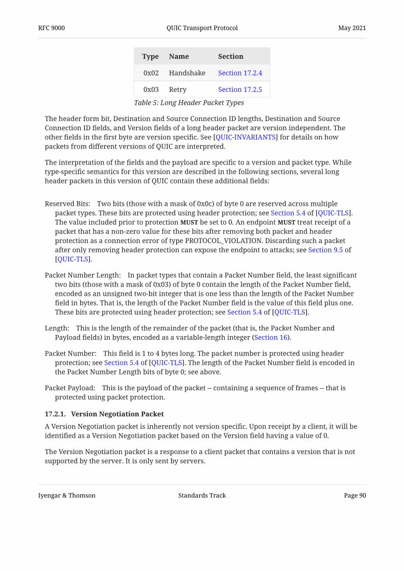
Reserved Bits:
Packet Number Length:
Length:
Packet Number:
Packet Payload:
The header form bit, Destination and Source Connection ID lengths, Destination and SourceConnection ID fields, and Version fields of a long header packet are version independent. Theother fields in the first byte are version specific. See for details on howpackets from different versions of QUIC are interpreted.
The interpretation of the fields and the payload are specific to a version and packet type. Whiletype-specific semantics for this version are described in the following sections, several longheader packets in this version of QUIC contain these additional fields:
Two bits (those with a mask of 0x0c) of byte 0 are reserved across multiplepacket types. These bits are protected using header protection; see .The value included prior to protection be set to 0. An endpoint treat receipt of apacket that has a non-zero value for these bits after removing both packet and headerprotection as a connection error of type PROTOCOL_VIOLATION. Discarding such a packetafter only removing header protection can expose the endpoint to attacks; see
.
In packet types that contain a Packet Number field, the least significanttwo bits (those with a mask of 0x03) of byte 0 contain the length of the Packet Number field,encoded as an unsigned two-bit integer that is one less than the length of the Packet Numberfield in bytes. That is, the length of the Packet Number field is the value of this field plus one.These bits are protected using header protection; see .
This is the length of the remainder of the packet (that is, the Packet Number andPayload fields) in bytes, encoded as a variable-length integer (Section 16).
This field is 1 to 4 bytes long. The packet number is protected using headerprotection; see . The length of the Packet Number field is encoded inthe Packet Number Length bits of byte 0; see above.
This is the payload of the packet -- containing a sequence of frames -- that isprotected using packet protection.
Type Name Section
0x02 Handshake Section 17.2.4
0x03 Retry Section 17.2.5
Table 5: Long Header Packet Types
[QUIC-INVARIANTS]
Section 5.4 of [QUIC-TLS]MUST MUST
Section 9.5 of[QUIC-TLS]
Section 5.4 of [QUIC-TLS]
Section 5.4 of [QUIC-TLS]
17.2.1. Version Negotiation Packet
A Version Negotiation packet is inherently not version specific. Upon receipt by a client, it will beidentified as a Version Negotiation packet based on the Version field having a value of 0.
The Version Negotiation packet is a response to a client packet that contains a version that is notsupported by the server. It is only sent by servers.
RFC 9000 QUIC Transport Protocol May 2021
Iyengar & Thomson Standards Track Page 90

The layout of a Version Negotiation packet is:
The value in the Unused field is set to an arbitrary value by the server. Clients ignore thevalue of this field. Where QUIC might be multiplexed with other protocols (see ),servers set the most significant bit of this field (0x40) to 1 so that Version Negotiationpackets appear to have the Fixed Bit field. Note that other versions of QUIC might not make asimilar recommendation.
The Version field of a Version Negotiation packet be set to 0x00000000.
The server include the value from the Source Connection ID field of the packet it receivesin the Destination Connection ID field. The value for Source Connection ID be copied fromthe Destination Connection ID of the received packet, which is initially randomly selected by aclient. Echoing both connection IDs gives clients some assurance that the server received thepacket and that the Version Negotiation packet was not generated by an entity that did notobserve the Initial packet.
Future versions of QUIC could have different requirements for the lengths of connection IDs. Inparticular, connection IDs might have a smaller minimum length or a greater maximum length.Version-specific rules for the connection ID therefore influence a decision aboutwhether to send a Version Negotiation packet.
The remainder of the Version Negotiation packet is a list of 32-bit versions that the serversupports.
A Version Negotiation packet is not acknowledged. It is only sent in response to a packet thatindicates an unsupported version; see Section 5.2.2.
The Version Negotiation packet does not include the Packet Number and Length fields present inother packets that use the long header form. Consequently, a Version Negotiation packetconsumes an entire UDP datagram.
A server send more than one Version Negotiation packet in response to a single UDPdatagram.
See Section 6 for a description of the version negotiation process.
Figure 14: Version Negotiation Packet
Version Negotiation Packet { Header Form (1) = 1, Unused (7), Version (32) = 0, Destination Connection ID Length (8), Destination Connection ID (0..2040), Source Connection ID Length (8), Source Connection ID (0..2040), Supported Version (32) ...,}
MUST[RFC7983]
SHOULD
MUST
MUSTMUST
MUST NOT
MUST NOT
RFC 9000 QUIC Transport Protocol May 2021
Iyengar & Thomson Standards Track Page 91

Token Length:
Token:
17.2.2. Initial Packet
An Initial packet uses long headers with a type value of 0x00. It carries the first CRYPTO framessent by the client and server to perform key exchange, and it carries ACK frames in eitherdirection.
The Initial packet contains a long header as well as the Length and Packet Number fields; see Section 17.2. The first byte contains the Reserved and Packet Number Length bits; see also Section 17.2. Between the Source Connection ID and Length fields, there are two additional fieldsspecific to the Initial packet.
A variable-length integer specifying the length of the Token field, in bytes. Thisvalue is 0 if no token is present. Initial packets sent by the server set the Token Lengthfield to 0; clients that receive an Initial packet with a non-zero Token Length field eitherdiscard the packet or generate a connection error of type PROTOCOL_VIOLATION.
The value of the token that was previously provided in a Retry packet or NEW_TOKENframe; see Section 8.1.
In order to prevent tampering by version-unaware middleboxes, Initial packets are protectedwith connection- and version-specific keys (Initial keys) as described in . Thisprotection does not provide confidentiality or integrity against attackers that can observepackets, but it does prevent attackers that cannot observe packets from spoofing Initial packets.
The client and server use the Initial packet type for any packet that contains an initialcryptographic handshake message. This includes all cases where a new packet containing theinitial cryptographic message needs to be created, such as the packets sent after receiving a Retrypacket; see Section 17.2.5.
Figure 15: Initial Packet
Initial Packet { Header Form (1) = 1, Fixed Bit (1) = 1, Long Packet Type (2) = 0, Reserved Bits (2), Packet Number Length (2), Version (32), Destination Connection ID Length (8), Destination Connection ID (0..160), Source Connection ID Length (8), Source Connection ID (0..160), Token Length (i), Token (..), Length (i), Packet Number (8..32), Packet Payload (8..),}
MUSTMUST
[QUIC-TLS]
RFC 9000 QUIC Transport Protocol May 2021
Iyengar & Thomson Standards Track Page 92

A server sends its first Initial packet in response to a client Initial. A server send multipleInitial packets. The cryptographic key exchange could require multiple round trips orretransmissions of this data.
The payload of an Initial packet includes a CRYPTO frame (or frames) containing a cryptographichandshake message, ACK frames, or both. PING, PADDING, and CONNECTION_CLOSE frames oftype 0x1c are also permitted. An endpoint that receives an Initial packet containing other framescan either discard the packet as spurious or treat it as a connection error.
The first packet sent by a client always includes a CRYPTO frame that contains the start or all ofthe first cryptographic handshake message. The first CRYPTO frame sent always begins at anoffset of 0; see Section 7.
Note that if the server sends a TLS HelloRetryRequest (see ), the clientwill send another series of Initial packets. These Initial packets will continue the cryptographichandshake and will contain CRYPTO frames starting at an offset matching the size of the CRYPTOframes sent in the first flight of Initial packets.
MAY
Section 4.7 of [QUIC-TLS]
17.2.2.1. Abandoning Initial Packets A client stops both sending and processing Initial packets when it sends its first Handshakepacket. A server stops sending and processing Initial packets when it receives its first Handshakepacket. Though packets might still be in flight or awaiting acknowledgment, no further Initialpackets need to be exchanged beyond this point. Initial packet protection keys are discarded (see
) along with any loss recovery and congestion control state; see .
Any data in CRYPTO frames is discarded -- and no longer retransmitted -- when Initial keys arediscarded.
Section 4.9.1 of [QUIC-TLS] Section6.4 of [QUIC-RECOVERY]
17.2.3. 0-RTT
A 0-RTT packet uses long headers with a type value of 0x01, followed by the Length and PacketNumber fields; see Section 17.2. The first byte contains the Reserved and Packet Number Lengthbits; see Section 17.2. A 0-RTT packet is used to carry "early" data from the client to the server aspart of the first flight, prior to handshake completion. As part of the TLS handshake, the servercan accept or reject this early data.
See for a discussion of 0-RTT data and its limitations.Section 2.3 of [TLS13]
RFC 9000 QUIC Transport Protocol May 2021
Iyengar & Thomson Standards Track Page 93

Packet numbers for 0-RTT protected packets use the same space as 1-RTT protected packets.
After a client receives a Retry packet, 0-RTT packets are likely to have been lost or discarded bythe server. A client attempt to resend data in 0-RTT packets after it sends a new Initialpacket. New packet numbers be used for any new packets that are sent; as described in Section 17.2.5.3, reusing packet numbers could compromise packet protection.
A client only receives acknowledgments for its 0-RTT packets once the handshake is complete, asdefined in .
A client send 0-RTT packets once it starts processing 1-RTT packets from the server.This means that 0-RTT packets cannot contain any response to frames from 1-RTT packets. Forinstance, a client cannot send an ACK frame in a 0-RTT packet, because that can onlyacknowledge a 1-RTT packet. An acknowledgment for a 1-RTT packet be carried in a 1-RTTpacket.
A server treat a violation of remembered limits (Section 7.4.1) as a connection error ofan appropriate type (for instance, a FLOW_CONTROL_ERROR for exceeding stream data limits).
Figure 16: 0-RTT Packet
0-RTT Packet { Header Form (1) = 1, Fixed Bit (1) = 1, Long Packet Type (2) = 1, Reserved Bits (2), Packet Number Length (2), Version (32), Destination Connection ID Length (8), Destination Connection ID (0..160), Source Connection ID Length (8), Source Connection ID (0..160), Length (i), Packet Number (8..32), Packet Payload (8..),}
SHOULDMUST
Section 4.1.1 of [QUIC-TLS]
MUST NOT
MUST
SHOULD
17.2.4. Handshake Packet
A Handshake packet uses long headers with a type value of 0x02, followed by the Length andPacket Number fields; see Section 17.2. The first byte contains the Reserved and Packet NumberLength bits; see Section 17.2. It is used to carry cryptographic handshake messages andacknowledgments from the server and client.
RFC 9000 QUIC Transport Protocol May 2021
Iyengar & Thomson Standards Track Page 94

Once a client has received a Handshake packet from a server, it uses Handshake packets to sendsubsequent cryptographic handshake messages and acknowledgments to the server.
The Destination Connection ID field in a Handshake packet contains a connection ID that ischosen by the recipient of the packet; the Source Connection ID includes the connection ID thatthe sender of the packet wishes to use; see Section 7.2.
Handshake packets have their own packet number space, and thus the first Handshake packetsent by a server contains a packet number of 0.
The payload of this packet contains CRYPTO frames and could contain PING, PADDING, or ACKframes. Handshake packets contain CONNECTION_CLOSE frames of type 0x1c. Endpoints
treat receipt of Handshake packets with other frames as a connection error of typePROTOCOL_VIOLATION.
Like Initial packets (see Section 17.2.2.1), data in CRYPTO frames for Handshake packets isdiscarded -- and no longer retransmitted -- when Handshake protection keys are discarded.
Figure 17: Handshake Protected Packet
Handshake Packet { Header Form (1) = 1, Fixed Bit (1) = 1, Long Packet Type (2) = 2, Reserved Bits (2), Packet Number Length (2), Version (32), Destination Connection ID Length (8), Destination Connection ID (0..160), Source Connection ID Length (8), Source Connection ID (0..160), Length (i), Packet Number (8..32), Packet Payload (8..),}
MAYMUST
17.2.5. Retry Packet
As shown in Figure 18, a Retry packet uses a long packet header with a type value of 0x03. Itcarries an address validation token created by the server. It is used by a server that wishes toperform a retry; see Section 8.1.
RFC 9000 QUIC Transport Protocol May 2021
Iyengar & Thomson Standards Track Page 95

Retry Token:
Retry Integrity Tag:
A Retry packet does not contain any protected fields. The value in the Unused field is set to anarbitrary value by the server; a client ignore these bits. In addition to the fields from thelong header, it contains these additional fields:
An opaque token that the server can use to validate the client's address.
Defined in Section of .
Figure 18: Retry Packet
Retry Packet { Header Form (1) = 1, Fixed Bit (1) = 1, Long Packet Type (2) = 3, Unused (4), Version (32), Destination Connection ID Length (8), Destination Connection ID (0..160), Source Connection ID Length (8), Source Connection ID (0..160), Retry Token (..), Retry Integrity Tag (128),}
MUST
5.8 ("Retry Packet Integrity") [QUIC-TLS]
17.2.5.1. Sending a Retry Packet The server populates the Destination Connection ID with the connection ID that the clientincluded in the Source Connection ID of the Initial packet.
The server includes a connection ID of its choice in the Source Connection ID field. This value be equal to the Destination Connection ID field of the packet sent by the client. A client
discard a Retry packet that contains a Source Connection ID field that is identical to theDestination Connection ID field of its Initial packet. The client use the value from theSource Connection ID field of the Retry packet in the Destination Connection ID field ofsubsequent packets that it sends.
A server send Retry packets in response to Initial and 0-RTT packets. A server can eitherdiscard or buffer 0-RTT packets that it receives. A server can send multiple Retry packets as itreceives Initial or 0-RTT packets. A server send more than one Retry packet inresponse to a single UDP datagram.
MUST NOTMUST
MUST
MAY
MUST NOT
17.2.5.2. Handling a Retry Packet A client accept and process at most one Retry packet for each connection attempt. After theclient has received and processed an Initial or Retry packet from the server, it discard anysubsequent Retry packets that it receives.
MUSTMUST
RFC 9000 QUIC Transport Protocol May 2021
Iyengar & Thomson Standards Track Page 96

Clients discard Retry packets that have a Retry Integrity Tag that cannot be validated; see . This diminishes an attacker's ability to inject a Retry packet and
protects against accidental corruption of Retry packets. A client discard a Retry packet witha zero-length Retry Token field.
The client responds to a Retry packet with an Initial packet that includes the provided Retrytoken to continue connection establishment.
A client sets the Destination Connection ID field of this Initial packet to the value from the SourceConnection ID field in the Retry packet. Changing the Destination Connection ID field also resultsin a change to the keys used to protect the Initial packet. It also sets the Token field to the tokenprovided in the Retry packet. The client change the Source Connection ID because theserver could include the connection ID as part of its token validation logic; see Section 8.1.4.
A Retry packet does not include a packet number and cannot be explicitly acknowledged by aclient.
MUSTSection 5.8 of [QUIC-TLS]
MUST
MUST NOT
17.2.5.3. Continuing a Handshake after Retry Subsequent Initial packets from the client include the connection ID and token values from theRetry packet. The client copies the Source Connection ID field from the Retry packet to theDestination Connection ID field and uses this value until an Initial packet with an updated valueis received; see Section 7.2. The value of the Token field is copied to all subsequent Initial packets;see Section 8.1.2.
Other than updating the Destination Connection ID and Token fields, the Initial packet sent by theclient is subject to the same restrictions as the first Initial packet. A client use the samecryptographic handshake message it included in this packet. A server treat a packet thatcontains a different cryptographic handshake message as a connection error or discard it. Notethat including a Token field reduces the available space for the cryptographic handshakemessage, which might result in the client needing to send multiple Initial packets.
A client attempt 0-RTT after receiving a Retry packet by sending 0-RTT packets to theconnection ID provided by the server.
A client reset the packet number for any packet number space after processing a Retrypacket. In particular, 0-RTT packets contain confidential information that will most likely beretransmitted on receiving a Retry packet. The keys used to protect these new 0-RTT packets willnot change as a result of responding to a Retry packet. However, the data sent in these packetscould be different than what was sent earlier. Sending these new packets with the same packetnumber is likely to compromise the packet protection for those packets because the same keyand nonce could be used to protect different content. A server abort the connection if itdetects that the client reset the packet number.
The connection IDs used in Initial and Retry packets exchanged between client and server arecopied to the transport parameters and validated as described in Section 7.3.
MUSTMAY
MAY
MUST NOT
MAY
RFC 9000 QUIC Transport Protocol May 2021
Iyengar & Thomson Standards Track Page 97

17.3. Short Header Packets This version of QUIC defines a single packet type that uses the short packet header.
Header Form:
Fixed Bit:
Spin Bit:
Reserved Bits:
Key Phase:
17.3.1. 1-RTT Packet
A 1-RTT packet uses a short packet header. It is used after the version and 1-RTT keys arenegotiated.
1-RTT packets contain the following fields:
The most significant bit (0x80) of byte 0 is set to 0 for the short header.
The next bit (0x40) of byte 0 is set to 1. Packets containing a zero value for this bit arenot valid packets in this version and be discarded. A value of 1 for this bit allows QUICto coexist with other protocols; see .
The third most significant bit (0x20) of byte 0 is the latency spin bit, set as described in Section 17.4.
The next two bits (those with a mask of 0x18) of byte 0 are reserved. These bitsare protected using header protection; see . The value included priorto protection be set to 0. An endpoint treat receipt of a packet that has a non-zerovalue for these bits, after removing both packet and header protection, as a connection errorof type PROTOCOL_VIOLATION. Discarding such a packet after only removing headerprotection can expose the endpoint to attacks; see .
The next bit (0x04) of byte 0 indicates the key phase, which allows a recipient of apacket to identify the packet protection keys that are used to protect the packet. See
for details. This bit is protected using header protection; see .
Figure 19: 1-RTT Packet
1-RTT Packet { Header Form (1) = 0, Fixed Bit (1) = 1, Spin Bit (1), Reserved Bits (2), Key Phase (1), Packet Number Length (2), Destination Connection ID (0..160), Packet Number (8..32), Packet Payload (8..),}
MUST[RFC7983]
Section 5.4 of [QUIC-TLS]MUST MUST
Section 9.5 of [QUIC-TLS]
[QUIC-TLS] Section 5.4 of [QUIC-TLS]
RFC 9000 QUIC Transport Protocol May 2021
Iyengar & Thomson Standards Track Page 98

Packet Number Length:
Destination Connection ID:
Packet Number:
Packet Payload:
The least significant two bits (those with a mask of 0x03) of byte 0contain the length of the Packet Number field, encoded as an unsigned two-bit integer that isone less than the length of the Packet Number field in bytes. That is, the length of the PacketNumber field is the value of this field plus one. These bits are protected using headerprotection; see .
The Destination Connection ID is a connection ID that is chosen bythe intended recipient of the packet. See Section 5.1 for more details.
The Packet Number field is 1 to 4 bytes long. The packet number is protectedusing header protection; see . The length of the Packet Number fieldis encoded in Packet Number Length field. See Section 17.1 for details.
1-RTT packets always include a 1-RTT protected payload.
The header form bit and the Destination Connection ID field of a short header packet are versionindependent. The remaining fields are specific to the selected QUIC version. See
for details on how packets from different versions of QUIC are interpreted.
Section 5.4 of [QUIC-TLS]
Section 5.4 of [QUIC-TLS]
[QUIC-INVARIANTS]
17.4. Latency Spin Bit The latency spin bit, which is defined for 1-RTT packets (Section 17.3.1), enables passive latencymonitoring from observation points on the network path throughout the duration of aconnection. The server reflects the spin value received, while the client "spins" it after one RTT.On-path observers can measure the time between two spin bit toggle events to estimate the end-to-end RTT of a connection.
The spin bit is only present in 1-RTT packets, since it is possible to measure the initial RTT of aconnection by observing the handshake. Therefore, the spin bit is available after versionnegotiation and connection establishment are completed. On-path measurement and use of thelatency spin bit are further discussed in .
The spin bit is an feature of this version of QUIC. An endpoint that does not supportthis feature disable it, as defined below.
Each endpoint unilaterally decides if the spin bit is enabled or disabled for a connection.Implementations allow administrators of clients and servers to disable the spin bit eitherglobally or on a per-connection basis. Even when the spin bit is not disabled by theadministrator, endpoints disable their use of the spin bit for a random selection of at leastone in every 16 network paths, or for one in every 16 connection IDs, in order to ensure thatQUIC connections that disable the spin bit are commonly observed on the network. As eachendpoint disables the spin bit independently, this ensures that the spin bit signal is disabled onapproximately one in eight network paths.
When the spin bit is disabled, endpoints set the spin bit to any value and ignore anyincoming value. It is that endpoints set the spin bit to a random value eitherchosen independently for each packet or chosen independently for each connection ID.
[QUIC-MANAGEABILITY]
OPTIONALMUST
MUST
MUST
MAY MUSTRECOMMENDED
RFC 9000 QUIC Transport Protocol May 2021
Iyengar & Thomson Standards Track Page 99

If the spin bit is enabled for the connection, the endpoint maintains a spin value for eachnetwork path and sets the spin bit in the packet header to the currently stored value when a 1-RTT packet is sent on that path. The spin value is initialized to 0 in the endpoint for each networkpath. Each endpoint also remembers the highest packet number seen from its peer on each path.
When a server receives a 1-RTT packet that increases the highest packet number seen by theserver from the client on a given network path, it sets the spin value for that path to be equal tothe spin bit in the received packet.
When a client receives a 1-RTT packet that increases the highest packet number seen by theclient from the server on a given network path, it sets the spin value for that path to the inverseof the spin bit in the received packet.
An endpoint resets the spin value for a network path to 0 when changing the connection ID beingused on that network path.
18. Transport Parameter Encoding The extension_data field of the quic_transport_parameters extension defined in contains the QUIC transport parameters. They are encoded as a sequence of transportparameters, as shown in Figure 20:
Each transport parameter is encoded as an (identifier, length, value) tuple, as shown in Figure 21:
The Transport Parameter Length field contains the length of the Transport Parameter Value fieldin bytes.
QUIC encodes transport parameters into a sequence of bytes, which is then included in thecryptographic handshake.
[QUIC-TLS]
Figure 20: Sequence of Transport Parameters
Transport Parameters { Transport Parameter (..) ...,}
Figure 21: Transport Parameter Encoding
Transport Parameter { Transport Parameter ID (i), Transport Parameter Length (i), Transport Parameter Value (..),}
RFC 9000 QUIC Transport Protocol May 2021
Iyengar & Thomson Standards Track Page 100

18.1. Reserved Transport Parameters Transport parameters with an identifier of the form 31 * N + 27 for integer values of N arereserved to exercise the requirement that unknown transport parameters be ignored. Thesetransport parameters have no semantics and can carry arbitrary values.
original_destination_connection_id (0x00):
max_idle_timeout (0x01):
stateless_reset_token (0x02):
max_udp_payload_size (0x03):
initial_max_data (0x04):
18.2. Transport Parameter Definitions This section details the transport parameters defined in this document.
Many transport parameters listed here have integer values. Those transport parameters that areidentified as integers use a variable-length integer encoding; see Section 16. Transportparameters have a default value of 0 if the transport parameter is absent, unless otherwisestated.
The following transport parameters are defined:
This parameter is the value of the DestinationConnection ID field from the first Initial packet sent by the client; see Section 7.3. Thistransport parameter is only sent by a server.
The maximum idle timeout is a value in milliseconds that is encodedas an integer; see (Section 10.1). Idle timeout is disabled when both endpoints omit thistransport parameter or specify a value of 0.
A stateless reset token is used in verifying a stateless reset; see Section 10.3. This parameter is a sequence of 16 bytes. This transport parameter besent by a client but be sent by a server. A server that does not send this transportparameter cannot use stateless reset (Section 10.3) for the connection ID negotiated during thehandshake.
The maximum UDP payload size parameter is an integer valuethat limits the size of UDP payloads that the endpoint is willing to receive. UDP datagramswith payloads larger than this limit are not likely to be processed by the receiver.
The default for this parameter is the maximum permitted UDP payload of 65527. Values below1200 are invalid.
This limit does act as an additional constraint on datagram size in the same way as the pathMTU, but it is a property of the endpoint and not the path; see Section 14. It is expected thatthis is the space an endpoint dedicates to holding incoming packets.
The initial maximum data parameter is an integer value that containsthe initial value for the maximum amount of data that can be sent on the connection. This isequivalent to sending a MAX_DATA (Section 19.9) for the connection immediately aftercompleting the handshake.
MUST NOTMAY
RFC 9000 QUIC Transport Protocol May 2021
Iyengar & Thomson Standards Track Page 101
initial_max_stream_data_bidi_local (0x05):
initial_max_stream_data_bidi_remote (0x06):
initial_max_stream_data_uni (0x07):
initial_max_streams_bidi (0x08):
initial_max_streams_uni (0x09):
ack_delay_exponent (0x0a):
max_ack_delay (0x0b):
This parameter is an integer value specifying theinitial flow control limit for locally initiated bidirectional streams. This limit applies to newlycreated bidirectional streams opened by the endpoint that sends the transport parameter. Inclient transport parameters, this applies to streams with an identifier with the least significanttwo bits set to 0x00; in server transport parameters, this applies to streams with the leastsignificant two bits set to 0x01.
This parameter is an integer value specifying theinitial flow control limit for peer-initiated bidirectional streams. This limit applies to newlycreated bidirectional streams opened by the endpoint that receives the transport parameter.In client transport parameters, this applies to streams with an identifier with the leastsignificant two bits set to 0x01; in server transport parameters, this applies to streams withthe least significant two bits set to 0x00.
This parameter is an integer value specifying the initialflow control limit for unidirectional streams. This limit applies to newly createdunidirectional streams opened by the endpoint that receives the transport parameter. Inclient transport parameters, this applies to streams with an identifier with the least significanttwo bits set to 0x03; in server transport parameters, this applies to streams with the leastsignificant two bits set to 0x02.
The initial maximum bidirectional streams parameter is aninteger value that contains the initial maximum number of bidirectional streams theendpoint that receives this transport parameter is permitted to initiate. If this parameter isabsent or zero, the peer cannot open bidirectional streams until a MAX_STREAMS frame issent. Setting this parameter is equivalent to sending a MAX_STREAMS (Section 19.11) of thecorresponding type with the same value.
The initial maximum unidirectional streams parameter is aninteger value that contains the initial maximum number of unidirectional streams theendpoint that receives this transport parameter is permitted to initiate. If this parameter isabsent or zero, the peer cannot open unidirectional streams until a MAX_STREAMS frame issent. Setting this parameter is equivalent to sending a MAX_STREAMS (Section 19.11) of thecorresponding type with the same value.
The acknowledgment delay exponent is an integer value indicatingan exponent used to decode the ACK Delay field in the ACK frame (Section 19.3). If this value isabsent, a default value of 3 is assumed (indicating a multiplier of 8). Values above 20 areinvalid.
The maximum acknowledgment delay is an integer value indicating themaximum amount of time in milliseconds by which the endpoint will delay sendingacknowledgments. This value include the receiver's expected delays in alarms firing.For example, if a receiver sets a timer for 5ms and alarms commonly fire up to 1ms late, thenit should send a max_ack_delay of 6ms. If this value is absent, a default of 25 milliseconds isassumed. Values of 214 or greater are invalid.
SHOULD
RFC 9000 QUIC Transport Protocol May 2021
Iyengar & Thomson Standards Track Page 102

disable_active_migration (0x0c):
preferred_address (0x0d):
active_connection_id_limit (0x0e):
The disable active migration transport parameter is included ifthe endpoint does not support active connection migration (Section 9) on the address beingused during the handshake. An endpoint that receives this transport parameter usea new local address when sending to the address that the peer used during the handshake.This transport parameter does not prohibit connection migration after a client has acted on apreferred_address transport parameter. This parameter is a zero-length value.
The server's preferred address is used to effect a change in serveraddress at the end of the handshake, as described in Section 9.6. This transport parameter isonly sent by a server. Servers choose to only send a preferred address of one addressfamily by sending an all-zero address and port (0.0.0.0:0 or [::]:0) for the other family. IPaddresses are encoded in network byte order.
The preferred_address transport parameter contains an address and port for both IPv4 andIPv6. The four-byte IPv4 Address field is followed by the associated two-byte IPv4 Port field.This is followed by a 16-byte IPv6 Address field and two-byte IPv6 Port field. After address andport pairs, a Connection ID Length field describes the length of the following Connection IDfield. Finally, a 16-byte Stateless Reset Token field includes the stateless reset token associatedwith the connection ID. The format of this transport parameter is shown in Figure 22 below.
The Connection ID field and the Stateless Reset Token field contain an alternative connectionID that has a sequence number of 1; see Section 5.1.1. Having these values sent alongside thepreferred address ensures that there will be at least one unused active connection ID whenthe client initiates migration to the preferred address.
The Connection ID and Stateless Reset Token fields of a preferred address are identical insyntax and semantics to the corresponding fields of a NEW_CONNECTION_ID frame (Section19.15). A server that chooses a zero-length connection ID provide a preferredaddress. Similarly, a server include a zero-length connection ID in this transportparameter. A client treat a violation of these requirements as a connection error of typeTRANSPORT_PARAMETER_ERROR.
This is an integer value specifying the maximum number ofconnection IDs from the peer that an endpoint is willing to store. This value includes theconnection ID received during the handshake, that received in the preferred_address
MUST NOT
MAY
MUST NOTMUST NOT
MUST
Figure 22: Preferred Address Format
Preferred Address { IPv4 Address (32), IPv4 Port (16), IPv6 Address (128), IPv6 Port (16), Connection ID Length (8), Connection ID (..), Stateless Reset Token (128),}
RFC 9000 QUIC Transport Protocol May 2021
Iyengar & Thomson Standards Track Page 103

initial_source_connection_id (0x0f):
retry_source_connection_id (0x10):
transport parameter, and those received in NEW_CONNECTION_ID frames. The value of theactive_connection_id_limit parameter be at least 2. An endpoint that receives a valueless than 2 close the connection with an error of type TRANSPORT_PARAMETER_ERROR.If this transport parameter is absent, a default of 2 is assumed. If an endpoint issues a zero-length connection ID, it will never send a NEW_CONNECTION_ID frame and therefore ignoresthe active_connection_id_limit value received from its peer.
This is the value that the endpoint included in the SourceConnection ID field of the first Initial packet it sends for the connection; see Section 7.3.
This is the value that the server included in the SourceConnection ID field of a Retry packet; see Section 7.3. This transport parameter is only sent bya server.
If present, transport parameters that set initial per-stream flow control limits(initial_max_stream_data_bidi_local, initial_max_stream_data_bidi_remote, andinitial_max_stream_data_uni) are equivalent to sending a MAX_STREAM_DATA frame (Section19.10) on every stream of the corresponding type immediately after opening. If the transportparameter is absent, streams of that type start with a flow control limit of 0.
A client include any server-only transport parameter:original_destination_connection_id, preferred_address, retry_source_connection_id, orstateless_reset_token. A server treat receipt of any of these transport parameters as aconnection error of type TRANSPORT_PARAMETER_ERROR.
MUSTMUST
MUST NOT
MUST
19. Frame Types and Formats As described in Section 12.4, packets contain one or more frames. This section describes theformat and semantics of the core QUIC frame types.
19.1. PADDING Frames A PADDING frame (type=0x00) has no semantic value. PADDING frames can be used to increasethe size of a packet. Padding can be used to increase an Initial packet to the minimum requiredsize or to provide protection against traffic analysis for protected packets.
PADDING frames are formatted as shown in Figure 23, which shows that PADDING frames haveno content. That is, a PADDING frame consists of the single byte that identifies the frame as aPADDING frame.
Figure 23: PADDING Frame Format
PADDING Frame { Type (i) = 0x00,}
RFC 9000 QUIC Transport Protocol May 2021
Iyengar & Thomson Standards Track Page 104

19.2. PING Frames Endpoints can use PING frames (type=0x01) to verify that their peers are still alive or to checkreachability to the peer.
PING frames are formatted as shown in Figure 24, which shows that PING frames have nocontent.
The receiver of a PING frame simply needs to acknowledge the packet containing this frame.
The PING frame can be used to keep a connection alive when an application or applicationprotocol wishes to prevent the connection from timing out; see Section 10.1.2.
Figure 24: PING Frame Format
PING Frame { Type (i) = 0x01,}
19.3. ACK Frames Receivers send ACK frames (types 0x02 and 0x03) to inform senders of packets they havereceived and processed. The ACK frame contains one or more ACK Ranges. ACK Ranges identifyacknowledged packets. If the frame type is 0x03, ACK frames also contain the cumulative countof QUIC packets with associated ECN marks received on the connection up until this point. QUICimplementations properly handle both types, and, if they have enabled ECN for packetsthey send, they use the information in the ECN section to manage their congestion state.
QUIC acknowledgments are irrevocable. Once acknowledged, a packet remains acknowledged,even if it does not appear in a future ACK frame. This is unlike reneging for TCP SelectiveAcknowledgments (SACKs) .
Packets from different packet number spaces can be identified using the same numeric value. Anacknowledgment for a packet needs to indicate both a packet number and a packet numberspace. This is accomplished by having each ACK frame only acknowledge packet numbers in thesame space as the packet in which the ACK frame is contained.
Version Negotiation and Retry packets cannot be acknowledged because they do not contain apacket number. Rather than relying on ACK frames, these packets are implicitly acknowledgedby the next Initial packet sent by the client.
ACK frames are formatted as shown in Figure 25.
MUSTSHOULD
[RFC2018]
RFC 9000 QUIC Transport Protocol May 2021
Iyengar & Thomson Standards Track Page 105

Largest Acknowledged:
ACK Delay:
ACK Range Count:
First ACK Range:
ACK Ranges:
ECN Counts:
ACK frames contain the following fields:
A variable-length integer representing the largest packet number thepeer is acknowledging; this is usually the largest packet number that the peer has receivedprior to generating the ACK frame. Unlike the packet number in the QUIC long or shortheader, the value in an ACK frame is not truncated.
A variable-length integer encoding the acknowledgment delay in microseconds; see Section 13.2.5. It is decoded by multiplying the value in the field by 2 to the power of theack_delay_exponent transport parameter sent by the sender of the ACK frame; see Section18.2. Compared to simply expressing the delay as an integer, this encoding allows for a largerrange of values within the same number of bytes, at the cost of lower resolution.
A variable-length integer specifying the number of ACK Range fields in theframe.
A variable-length integer indicating the number of contiguous packetspreceding the Largest Acknowledged that are being acknowledged. That is, the smallestpacket acknowledged in the range is determined by subtracting the First ACK Range valuefrom the Largest Acknowledged field.
Contains additional ranges of packets that are alternately not acknowledged (Gap)and acknowledged (ACK Range); see Section 19.3.1.
The three ECN counts; see Section 19.3.2.
Figure 25: ACK Frame Format
ACK Frame { Type (i) = 0x02..0x03, Largest Acknowledged (i), ACK Delay (i), ACK Range Count (i), First ACK Range (i), ACK Range (..) ..., [ECN Counts (..)],}
19.3.1. ACK Ranges
Each ACK Range consists of alternating Gap and ACK Range Length values in descending packetnumber order. ACK Ranges can be repeated. The number of Gap and ACK Range Length values isdetermined by the ACK Range Count field; one of each value is present for each value in the ACKRange Count field.
ACK Ranges are structured as shown in Figure 26.
RFC 9000 QUIC Transport Protocol May 2021
Iyengar & Thomson Standards Track Page 106

Gap:
ACK Range Length:
The fields that form each ACK Range are:
A variable-length integer indicating the number of contiguous unacknowledged packetspreceding the packet number one lower than the smallest in the preceding ACK Range.
A variable-length integer indicating the number of contiguousacknowledged packets preceding the largest packet number, as determined by the precedingGap.
Gap and ACK Range Length values use a relative integer encoding for efficiency. Though eachencoded value is positive, the values are subtracted, so that each ACK Range describesprogressively lower-numbered packets.
Each ACK Range acknowledges a contiguous range of packets by indicating the number ofacknowledged packets that precede the largest packet number in that range. A value of 0indicates that only the largest packet number is acknowledged. Larger ACK Range values indicatea larger range, with corresponding lower values for the smallest packet number in the range.Thus, given a largest packet number for the range, the smallest value is determined by thefollowing formula:
An ACK Range acknowledges all packets between the smallest packet number and the largest,inclusive.
The largest value for an ACK Range is determined by cumulatively subtracting the size of allpreceding ACK Range Lengths and Gaps.
Each Gap indicates a range of packets that are not being acknowledged. The number of packetsin the gap is one higher than the encoded value of the Gap field.
The value of the Gap field establishes the largest packet number value for the subsequent ACKRange using the following formula:
If any computed packet number is negative, an endpoint generate a connection error oftype FRAME_ENCODING_ERROR.
Figure 26: ACK Ranges
ACK Range { Gap (i), ACK Range Length (i),}
smallest = largest - ack_range
largest = previous_smallest - gap - 2
MUST
RFC 9000 QUIC Transport Protocol May 2021
Iyengar & Thomson Standards Track Page 107

ECT0 Count:
ECT1 Count:
ECN-CE Count:
19.3.2. ECN Counts
The ACK frame uses the least significant bit of the type value (that is, type 0x03) to indicate ECNfeedback and report receipt of QUIC packets with associated ECN codepoints of ECT(0), ECT(1), orECN-CE in the packet's IP header. ECN counts are only present when the ACK frame type is 0x03.
When present, there are three ECN counts, as shown in Figure 27.
The ECN count fields are:
A variable-length integer representing the total number of packets received withthe ECT(0) codepoint in the packet number space of the ACK frame.
A variable-length integer representing the total number of packets received withthe ECT(1) codepoint in the packet number space of the ACK frame.
A variable-length integer representing the total number of packets received withthe ECN-CE codepoint in the packet number space of the ACK frame.
ECN counts are maintained separately for each packet number space.
Figure 27: ECN Count Format
ECN Counts { ECT0 Count (i), ECT1 Count (i), ECN-CE Count (i),}
19.4. RESET_STREAM Frames An endpoint uses a RESET_STREAM frame (type=0x04) to abruptly terminate the sending part ofa stream.
After sending a RESET_STREAM, an endpoint ceases transmission and retransmission of STREAMframes on the identified stream. A receiver of RESET_STREAM can discard any data that italready received on that stream.
An endpoint that receives a RESET_STREAM frame for a send-only stream terminate theconnection with error STREAM_STATE_ERROR.
RESET_STREAM frames are formatted as shown in Figure 28.
MUST
RFC 9000 QUIC Transport Protocol May 2021
Iyengar & Thomson Standards Track Page 108

Stream ID:
Application Protocol Error Code:
Final Size:
RESET_STREAM frames contain the following fields:
A variable-length integer encoding of the stream ID of the stream being terminated.
A variable-length integer containing the application protocolerror code (see Section 20.2) that indicates why the stream is being closed.
A variable-length integer indicating the final size of the stream by theRESET_STREAM sender, in units of bytes; see Section 4.5.
Figure 28: RESET_STREAM Frame Format
RESET_STREAM Frame { Type (i) = 0x04, Stream ID (i), Application Protocol Error Code (i), Final Size (i),}
Stream ID:
Application Protocol Error Code:
19.5. STOP_SENDING Frames An endpoint uses a STOP_SENDING frame (type=0x05) to communicate that incoming data isbeing discarded on receipt per application request. STOP_SENDING requests that a peer ceasetransmission on a stream.
A STOP_SENDING frame can be sent for streams in the "Recv" or "Size Known" states; see Section3.2. Receiving a STOP_SENDING frame for a locally initiated stream that has not yet been created
be treated as a connection error of type STREAM_STATE_ERROR. An endpoint that receivesa STOP_SENDING frame for a receive-only stream terminate the connection with errorSTREAM_STATE_ERROR.
STOP_SENDING frames are formatted as shown in Figure 29.
STOP_SENDING frames contain the following fields:
A variable-length integer carrying the stream ID of the stream being ignored.
A variable-length integer containing the application-specifiedreason the sender is ignoring the stream; see Section 20.2.
MUSTMUST
Figure 29: STOP_SENDING Frame Format
STOP_SENDING Frame { Type (i) = 0x05, Stream ID (i), Application Protocol Error Code (i),}
RFC 9000 QUIC Transport Protocol May 2021
Iyengar & Thomson Standards Track Page 109

Offset:
Length:
Crypto Data:
19.6. CRYPTO Frames A CRYPTO frame (type=0x06) is used to transmit cryptographic handshake messages. It can besent in all packet types except 0-RTT. The CRYPTO frame offers the cryptographic protocol an in-order stream of bytes. CRYPTO frames are functionally identical to STREAM frames, except thatthey do not bear a stream identifier; they are not flow controlled; and they do not carry markersfor optional offset, optional length, and the end of the stream.
CRYPTO frames are formatted as shown in Figure 30.
CRYPTO frames contain the following fields:
A variable-length integer specifying the byte offset in the stream for the data in thisCRYPTO frame.
A variable-length integer specifying the length of the Crypto Data field in this CRYPTOframe.
The cryptographic message data.
There is a separate flow of cryptographic handshake data in each encryption level, each of whichstarts at an offset of 0. This implies that each encryption level is treated as a separate CRYPTOstream of data.
The largest offset delivered on a stream -- the sum of the offset and data length -- cannot exceed262-1. Receipt of a frame that exceeds this limit be treated as a connection error of typeFRAME_ENCODING_ERROR or CRYPTO_BUFFER_EXCEEDED.
Unlike STREAM frames, which include a stream ID indicating to which stream the data belongs,the CRYPTO frame carries data for a single stream per encryption level. The stream does nothave an explicit end, so CRYPTO frames do not have a FIN bit.
Figure 30: CRYPTO Frame Format
CRYPTO Frame { Type (i) = 0x06, Offset (i), Length (i), Crypto Data (..),}
MUST
19.7. NEW_TOKEN Frames A server sends a NEW_TOKEN frame (type=0x07) to provide the client with a token to send in theheader of an Initial packet for a future connection.
NEW_TOKEN frames are formatted as shown in Figure 31.
RFC 9000 QUIC Transport Protocol May 2021
Iyengar & Thomson Standards Track Page 110

Token Length:
Token:
NEW_TOKEN frames contain the following fields:
A variable-length integer specifying the length of the token in bytes.
An opaque blob that the client can use with a future Initial packet. The token be empty. A client treat receipt of a NEW_TOKEN frame with an empty Token field as aconnection error of type FRAME_ENCODING_ERROR.
A client might receive multiple NEW_TOKEN frames that contain the same token value if packetscontaining the frame are incorrectly determined to be lost. Clients are responsible for discardingduplicate values, which might be used to link connection attempts; see Section 8.1.3.
Clients send NEW_TOKEN frames. A server treat receipt of a NEW_TOKEN frameas a connection error of type PROTOCOL_VIOLATION.
Figure 31: NEW_TOKEN Frame Format
NEW_TOKEN Frame { Type (i) = 0x07, Token Length (i), Token (..),}
MUST NOTMUST
MUST NOT MUST
19.8. STREAM Frames STREAM frames implicitly create a stream and carry stream data. The Type field in the STREAMframe takes the form 0b00001XXX (or the set of values from 0x08 to 0x0f). The three low-orderbits of the frame type determine the fields that are present in the frame:
The OFF bit (0x04) in the frame type is set to indicate that there is an Offset field present.When set to 1, the Offset field is present. When set to 0, the Offset field is absent and theStream Data starts at an offset of 0 (that is, the frame contains the first bytes of the stream, orthe end of a stream that includes no data). The LEN bit (0x02) in the frame type is set to indicate that there is a Length field present. Ifthis bit is set to 0, the Length field is absent and the Stream Data field extends to the end ofthe packet. If this bit is set to 1, the Length field is present. The FIN bit (0x01) indicates that the frame marks the end of the stream. The final size of thestream is the sum of the offset and the length of this frame.
An endpoint terminate the connection with error STREAM_STATE_ERROR if it receives aSTREAM frame for a locally initiated stream that has not yet been created, or for a send-onlystream.
STREAM frames are formatted as shown in Figure 32.
•
•
•
MUST
RFC 9000 QUIC Transport Protocol May 2021
Iyengar & Thomson Standards Track Page 111

Stream ID:
Offset:
Length:
Stream Data:
STREAM frames contain the following fields:
A variable-length integer indicating the stream ID of the stream; see Section 2.1.
A variable-length integer specifying the byte offset in the stream for the data in thisSTREAM frame. This field is present when the OFF bit is set to 1. When the Offset field isabsent, the offset is 0.
A variable-length integer specifying the length of the Stream Data field in this STREAMframe. This field is present when the LEN bit is set to 1. When the LEN bit is set to 0, theStream Data field consumes all the remaining bytes in the packet.
The bytes from the designated stream to be delivered.
When a Stream Data field has a length of 0, the offset in the STREAM frame is the offset of thenext byte that would be sent.
The first byte in the stream has an offset of 0. The largest offset delivered on a stream -- the sumof the offset and data length -- cannot exceed 262-1, as it is not possible to provide flow controlcredit for that data. Receipt of a frame that exceeds this limit be treated as a connectionerror of type FRAME_ENCODING_ERROR or FLOW_CONTROL_ERROR.
Figure 32: STREAM Frame Format
STREAM Frame { Type (i) = 0x08..0x0f, Stream ID (i), [Offset (i)], [Length (i)], Stream Data (..),}
MUST
19.9. MAX_DATA Frames A MAX_DATA frame (type=0x10) is used in flow control to inform the peer of the maximumamount of data that can be sent on the connection as a whole.
MAX_DATA frames are formatted as shown in Figure 33.
MAX_DATA frames contain the following field:
Figure 33: MAX_DATA Frame Format
MAX_DATA Frame { Type (i) = 0x10, Maximum Data (i),}
RFC 9000 QUIC Transport Protocol May 2021
Iyengar & Thomson Standards Track Page 112

Maximum Data: A variable-length integer indicating the maximum amount of data that can besent on the entire connection, in units of bytes.
All data sent in STREAM frames counts toward this limit. The sum of the final sizes on all streams-- including streams in terminal states -- exceed the value advertised by a receiver. Anendpoint terminate a connection with an error of type FLOW_CONTROL_ERROR if itreceives more data than the maximum data value that it has sent. This includes violations ofremembered limits in Early Data; see Section 7.4.1.
MUST NOTMUST
Stream ID:
Maximum Stream Data:
19.10. MAX_STREAM_DATA Frames A MAX_STREAM_DATA frame (type=0x11) is used in flow control to inform a peer of themaximum amount of data that can be sent on a stream.
A MAX_STREAM_DATA frame can be sent for streams in the "Recv" state; see Section 3.2.Receiving a MAX_STREAM_DATA frame for a locally initiated stream that has not yet beencreated be treated as a connection error of type STREAM_STATE_ERROR. An endpoint thatreceives a MAX_STREAM_DATA frame for a receive-only stream terminate the connectionwith error STREAM_STATE_ERROR.
MAX_STREAM_DATA frames are formatted as shown in Figure 34.
MAX_STREAM_DATA frames contain the following fields:
The stream ID of the affected stream, encoded as a variable-length integer.
A variable-length integer indicating the maximum amount of data thatcan be sent on the identified stream, in units of bytes.
When counting data toward this limit, an endpoint accounts for the largest received offset ofdata that is sent or received on the stream. Loss or reordering can mean that the largest receivedoffset on a stream can be greater than the total size of data received on that stream. ReceivingSTREAM frames might not increase the largest received offset.
The data sent on a stream exceed the largest maximum stream data value advertisedby the receiver. An endpoint terminate a connection with an error of typeFLOW_CONTROL_ERROR if it receives more data than the largest maximum stream data that ithas sent for the affected stream. This includes violations of remembered limits in Early Data; see Section 7.4.1.
MUSTMUST
Figure 34: MAX_STREAM_DATA Frame Format
MAX_STREAM_DATA Frame { Type (i) = 0x11, Stream ID (i), Maximum Stream Data (i),}
MUST NOTMUST
RFC 9000 QUIC Transport Protocol May 2021
Iyengar & Thomson Standards Track Page 113

Maximum Streams:
19.11. MAX_STREAMS Frames A MAX_STREAMS frame (type=0x12 or 0x13) informs the peer of the cumulative number ofstreams of a given type it is permitted to open. A MAX_STREAMS frame with a type of 0x12applies to bidirectional streams, and a MAX_STREAMS frame with a type of 0x13 applies tounidirectional streams.
MAX_STREAMS frames are formatted as shown in Figure 35.
MAX_STREAMS frames contain the following field:
A count of the cumulative number of streams of the corresponding typethat can be opened over the lifetime of the connection. This value cannot exceed 260, as it isnot possible to encode stream IDs larger than 262-1. Receipt of a frame that permits openingof a stream larger than this limit be treated as a connection error of typeFRAME_ENCODING_ERROR.
Loss or reordering can cause an endpoint to receive a MAX_STREAMS frame with a lower streamlimit than was previously received. MAX_STREAMS frames that do not increase the stream limit
be ignored.
An endpoint open more streams than permitted by the current stream limit set by itspeer. For instance, a server that receives a unidirectional stream limit of 3 is permitted to openstreams 3, 7, and 11, but not stream 15. An endpoint terminate a connection with an errorof type STREAM_LIMIT_ERROR if a peer opens more streams than was permitted. This includesviolations of remembered limits in Early Data; see Section 7.4.1.
Note that these frames (and the corresponding transport parameters) do not describe thenumber of streams that can be opened concurrently. The limit includes streams that have beenclosed as well as those that are open.
Figure 35: MAX_STREAMS Frame Format
MAX_STREAMS Frame { Type (i) = 0x12..0x13, Maximum Streams (i),}
MUST
MUST
MUST NOT
MUST
19.12. DATA_BLOCKED Frames A sender send a DATA_BLOCKED frame (type=0x14) when it wishes to send data but isunable to do so due to connection-level flow control; see Section 4. DATA_BLOCKED frames canbe used as input to tuning of flow control algorithms; see Section 4.2.
DATA_BLOCKED frames are formatted as shown in Figure 36.
SHOULD
RFC 9000 QUIC Transport Protocol May 2021
Iyengar & Thomson Standards Track Page 114
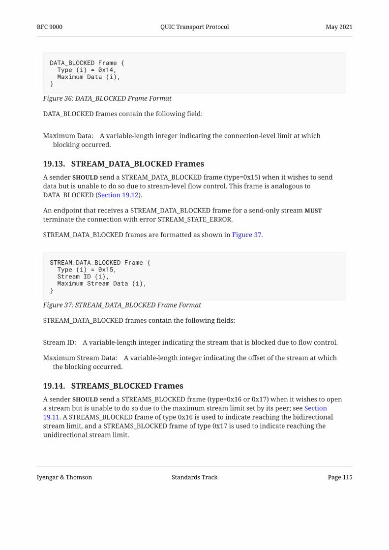
Maximum Data:
DATA_BLOCKED frames contain the following field:
A variable-length integer indicating the connection-level limit at whichblocking occurred.
Figure 36: DATA_BLOCKED Frame Format
DATA_BLOCKED Frame { Type (i) = 0x14, Maximum Data (i),}
Stream ID:
Maximum Stream Data:
19.13. STREAM_DATA_BLOCKED Frames A sender send a STREAM_DATA_BLOCKED frame (type=0x15) when it wishes to senddata but is unable to do so due to stream-level flow control. This frame is analogous toDATA_BLOCKED (Section 19.12).
An endpoint that receives a STREAM_DATA_BLOCKED frame for a send-only stream terminate the connection with error STREAM_STATE_ERROR.
STREAM_DATA_BLOCKED frames are formatted as shown in Figure 37.
STREAM_DATA_BLOCKED frames contain the following fields:
A variable-length integer indicating the stream that is blocked due to flow control.
A variable-length integer indicating the offset of the stream at whichthe blocking occurred.
SHOULD
MUST
Figure 37: STREAM_DATA_BLOCKED Frame Format
STREAM_DATA_BLOCKED Frame { Type (i) = 0x15, Stream ID (i), Maximum Stream Data (i),}
19.14. STREAMS_BLOCKED Frames A sender send a STREAMS_BLOCKED frame (type=0x16 or 0x17) when it wishes to opena stream but is unable to do so due to the maximum stream limit set by its peer; see Section19.11. A STREAMS_BLOCKED frame of type 0x16 is used to indicate reaching the bidirectionalstream limit, and a STREAMS_BLOCKED frame of type 0x17 is used to indicate reaching theunidirectional stream limit.
SHOULD
RFC 9000 QUIC Transport Protocol May 2021
Iyengar & Thomson Standards Track Page 115

Maximum Streams:
A STREAMS_BLOCKED frame does not open the stream, but informs the peer that a new streamwas needed and the stream limit prevented the creation of the stream.
STREAMS_BLOCKED frames are formatted as shown in Figure 38.
STREAMS_BLOCKED frames contain the following field:
A variable-length integer indicating the maximum number of streamsallowed at the time the frame was sent. This value cannot exceed 260, as it is not possible toencode stream IDs larger than 262-1. Receipt of a frame that encodes a larger stream ID be treated as a connection error of type STREAM_LIMIT_ERROR orFRAME_ENCODING_ERROR.
Figure 38: STREAMS_BLOCKED Frame Format
STREAMS_BLOCKED Frame { Type (i) = 0x16..0x17, Maximum Streams (i),}
MUST
Sequence Number:
Retire Prior To:
19.15. NEW_CONNECTION_ID Frames An endpoint sends a NEW_CONNECTION_ID frame (type=0x18) to provide its peer withalternative connection IDs that can be used to break linkability when migrating connections; see Section 9.5.
NEW_CONNECTION_ID frames are formatted as shown in Figure 39.
NEW_CONNECTION_ID frames contain the following fields:
The sequence number assigned to the connection ID by the sender, encodedas a variable-length integer; see Section 5.1.1.
A variable-length integer indicating which connection IDs should be retired; seeSection 5.1.2.
Figure 39: NEW_CONNECTION_ID Frame Format
NEW_CONNECTION_ID Frame { Type (i) = 0x18, Sequence Number (i), Retire Prior To (i), Length (8), Connection ID (8..160), Stateless Reset Token (128),}
RFC 9000 QUIC Transport Protocol May 2021
Iyengar & Thomson Standards Track Page 116

Length:
Connection ID:
Stateless Reset Token:
An 8-bit unsigned integer containing the length of the connection ID. Values less than 1and greater than 20 are invalid and be treated as a connection error of typeFRAME_ENCODING_ERROR.
A connection ID of the specified length.
A 128-bit value that will be used for a stateless reset when the associatedconnection ID is used; see Section 10.3.
An endpoint send this frame if it currently requires that its peer send packets with azero-length Destination Connection ID. Changing the length of a connection ID to or from zerolength makes it difficult to identify when the value of the connection ID changed. An endpointthat is sending packets with a zero-length Destination Connection ID treat receipt of aNEW_CONNECTION_ID frame as a connection error of type PROTOCOL_VIOLATION.
Transmission errors, timeouts, and retransmissions might cause the sameNEW_CONNECTION_ID frame to be received multiple times. Receipt of the same frame multipletimes be treated as a connection error. A receiver can use the sequence numbersupplied in the NEW_CONNECTION_ID frame to handle receiving the sameNEW_CONNECTION_ID frame multiple times.
If an endpoint receives a NEW_CONNECTION_ID frame that repeats a previously issuedconnection ID with a different Stateless Reset Token field value or a different Sequence Numberfield value, or if a sequence number is used for different connection IDs, the endpoint treatthat receipt as a connection error of type PROTOCOL_VIOLATION.
The Retire Prior To field applies to connection IDs established during connection setup and thepreferred_address transport parameter; see Section 5.1.2. The value in the Retire Prior To field
be less than or equal to the value in the Sequence Number field. Receiving a value in theRetire Prior To field that is greater than that in the Sequence Number field be treated as aconnection error of type FRAME_ENCODING_ERROR.
Once a sender indicates a Retire Prior To value, smaller values sent in subsequentNEW_CONNECTION_ID frames have no effect. A receiver ignore any Retire Prior To fieldsthat do not increase the largest received Retire Prior To value.
An endpoint that receives a NEW_CONNECTION_ID frame with a sequence number smaller thanthe Retire Prior To field of a previously received NEW_CONNECTION_ID frame send acorresponding RETIRE_CONNECTION_ID frame that retires the newly received connection ID,unless it has already done so for that sequence number.
MUST
MUST NOT
MUST
MUST NOT
MAY
MUSTMUST
MUST
MUST
19.16. RETIRE_CONNECTION_ID Frames An endpoint sends a RETIRE_CONNECTION_ID frame (type=0x19) to indicate that it will no longeruse a connection ID that was issued by its peer. This includes the connection ID provided duringthe handshake. Sending a RETIRE_CONNECTION_ID frame also serves as a request to the peer tosend additional connection IDs for future use; see Section 5.1. New connection IDs can bedelivered to a peer using the NEW_CONNECTION_ID frame (Section 19.15).
RFC 9000 QUIC Transport Protocol May 2021
Iyengar & Thomson Standards Track Page 117
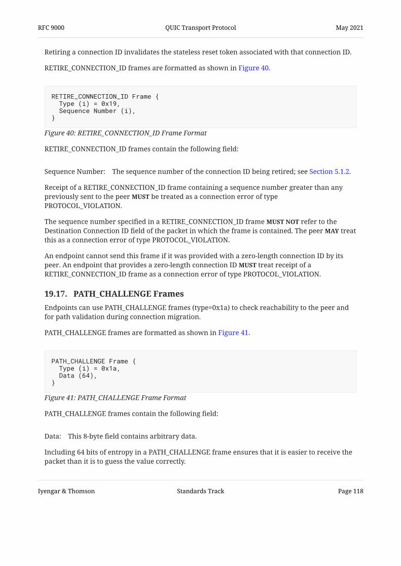
Sequence Number:
Retiring a connection ID invalidates the stateless reset token associated with that connection ID.
RETIRE_CONNECTION_ID frames are formatted as shown in Figure 40.
RETIRE_CONNECTION_ID frames contain the following field:
The sequence number of the connection ID being retired; see Section 5.1.2.
Receipt of a RETIRE_CONNECTION_ID frame containing a sequence number greater than anypreviously sent to the peer be treated as a connection error of typePROTOCOL_VIOLATION.
The sequence number specified in a RETIRE_CONNECTION_ID frame refer to theDestination Connection ID field of the packet in which the frame is contained. The peer treatthis as a connection error of type PROTOCOL_VIOLATION.
An endpoint cannot send this frame if it was provided with a zero-length connection ID by itspeer. An endpoint that provides a zero-length connection ID treat receipt of aRETIRE_CONNECTION_ID frame as a connection error of type PROTOCOL_VIOLATION.
Figure 40: RETIRE_CONNECTION_ID Frame Format
RETIRE_CONNECTION_ID Frame { Type (i) = 0x19, Sequence Number (i),}
MUST
MUST NOTMAY
MUST
Data:
19.17. PATH_CHALLENGE Frames Endpoints can use PATH_CHALLENGE frames (type=0x1a) to check reachability to the peer andfor path validation during connection migration.
PATH_CHALLENGE frames are formatted as shown in Figure 41.
PATH_CHALLENGE frames contain the following field:
This 8-byte field contains arbitrary data.
Including 64 bits of entropy in a PATH_CHALLENGE frame ensures that it is easier to receive thepacket than it is to guess the value correctly.
Figure 41: PATH_CHALLENGE Frame Format
PATH_CHALLENGE Frame { Type (i) = 0x1a, Data (64),}
RFC 9000 QUIC Transport Protocol May 2021
Iyengar & Thomson Standards Track Page 118
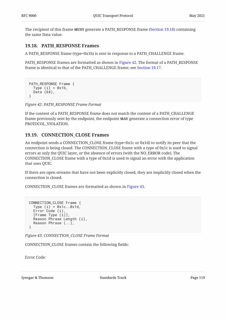
The recipient of this frame generate a PATH_RESPONSE frame (Section 19.18) containingthe same Data value.
MUST
19.18. PATH_RESPONSE Frames A PATH_RESPONSE frame (type=0x1b) is sent in response to a PATH_CHALLENGE frame.
PATH_RESPONSE frames are formatted as shown in Figure 42. The format of a PATH_RESPONSEframe is identical to that of the PATH_CHALLENGE frame; see Section 19.17.
If the content of a PATH_RESPONSE frame does not match the content of a PATH_CHALLENGEframe previously sent by the endpoint, the endpoint generate a connection error of typePROTOCOL_VIOLATION.
Figure 42: PATH_RESPONSE Frame Format
PATH_RESPONSE Frame { Type (i) = 0x1b, Data (64),}
MAY
Error Code:
19.19. CONNECTION_CLOSE Frames An endpoint sends a CONNECTION_CLOSE frame (type=0x1c or 0x1d) to notify its peer that theconnection is being closed. The CONNECTION_CLOSE frame with a type of 0x1c is used to signalerrors at only the QUIC layer, or the absence of errors (with the NO_ERROR code). TheCONNECTION_CLOSE frame with a type of 0x1d is used to signal an error with the applicationthat uses QUIC.
If there are open streams that have not been explicitly closed, they are implicitly closed when theconnection is closed.
CONNECTION_CLOSE frames are formatted as shown in Figure 43.
CONNECTION_CLOSE frames contain the following fields:
Figure 43: CONNECTION_CLOSE Frame Format
CONNECTION_CLOSE Frame { Type (i) = 0x1c..0x1d, Error Code (i), [Frame Type (i)], Reason Phrase Length (i), Reason Phrase (..),}
RFC 9000 QUIC Transport Protocol May 2021
Iyengar & Thomson Standards Track Page 119

Frame Type:
Reason Phrase Length:
Reason Phrase:
A variable-length integer that indicates the reason for closing this connection. ACONNECTION_CLOSE frame of type 0x1c uses codes from the space defined in Section 20.1. ACONNECTION_CLOSE frame of type 0x1d uses codes defined by the application protocol; see Section 20.2.
A variable-length integer encoding the type of frame that triggered the error. Avalue of 0 (equivalent to the mention of the PADDING frame) is used when the frame type isunknown. The application-specific variant of CONNECTION_CLOSE (type 0x1d) does notinclude this field.
A variable-length integer specifying the length of the reason phrase inbytes. Because a CONNECTION_CLOSE frame cannot be split between packets, any limits onpacket size will also limit the space available for a reason phrase.
Additional diagnostic information for the closure. This can be zero length if thesender chooses not to give details beyond the Error Code value. This be a UTF-8encoded string , though the frame does not carry information, such as languagetags, that would aid comprehension by any entity other than the one that created the text.
The application-specific variant of CONNECTION_CLOSE (type 0x1d) can only be sent using 0-RTTor 1-RTT packets; see Section 12.5. When an application wishes to abandon a connection duringthe handshake, an endpoint can send a CONNECTION_CLOSE frame (type 0x1c) with an errorcode of APPLICATION_ERROR in an Initial or Handshake packet.
SHOULD[RFC3629]
19.20. HANDSHAKE_DONE Frames The server uses a HANDSHAKE_DONE frame (type=0x1e) to signal confirmation of the handshaketo the client.
HANDSHAKE_DONE frames are formatted as shown in Figure 44, which shows thatHANDSHAKE_DONE frames have no content.
A HANDSHAKE_DONE frame can only be sent by the server. Servers send aHANDSHAKE_DONE frame before completing the handshake. A server treat receipt of aHANDSHAKE_DONE frame as a connection error of type PROTOCOL_VIOLATION.
Figure 44: HANDSHAKE_DONE Frame Format
HANDSHAKE_DONE Frame { Type (i) = 0x1e,}
MUST NOTMUST
RFC 9000 QUIC Transport Protocol May 2021
Iyengar & Thomson Standards Track Page 120

19.21. Extension Frames QUIC frames do not use a self-describing encoding. An endpoint therefore needs to understandthe syntax of all frames before it can successfully process a packet. This allows for efficientencoding of frames, but it means that an endpoint cannot send a frame of a type that is unknownto its peer.
An extension to QUIC that wishes to use a new type of frame first ensure that a peer is ableto understand the frame. An endpoint can use a transport parameter to signal its willingness toreceive extension frame types. One transport parameter can indicate support for one or moreextension frame types.
Extensions that modify or replace core protocol functionality (including frame types) will bedifficult to combine with other extensions that modify or replace the same functionality unlessthe behavior of the combination is explicitly defined. Such extensions define theirinteraction with previously defined extensions modifying the same protocol components.
Extension frames be congestion controlled and cause an ACK frame to be sent. Theexception is extension frames that replace or supplement the ACK frame. Extension frames arenot included in flow control unless specified in the extension.
An IANA registry is used to manage the assignment of frame types; see Section 22.4.
MUST
SHOULD
MUST MUST
20. Error Codes QUIC transport error codes and application error codes are 62-bit unsigned integers.
NO_ERROR (0x00):
INTERNAL_ERROR (0x01):
CONNECTION_REFUSED (0x02):
FLOW_CONTROL_ERROR (0x03):
STREAM_LIMIT_ERROR (0x04):
20.1. Transport Error Codes This section lists the defined QUIC transport error codes that can be used in aCONNECTION_CLOSE frame with a type of 0x1c. These errors apply to the entire connection.
An endpoint uses this with CONNECTION_CLOSE to signal that theconnection is being closed abruptly in the absence of any error.
The endpoint encountered an internal error and cannot continuewith the connection.
The server refused to accept a new connection.
An endpoint received more data than it permitted in itsadvertised data limits; see Section 4.
An endpoint received a frame for a stream identifier thatexceeded its advertised stream limit for the corresponding stream type.
RFC 9000 QUIC Transport Protocol May 2021
Iyengar & Thomson Standards Track Page 121

STREAM_STATE_ERROR (0x05):
FINAL_SIZE_ERROR (0x06):
FRAME_ENCODING_ERROR (0x07):
TRANSPORT_PARAMETER_ERROR (0x08):
CONNECTION_ID_LIMIT_ERROR (0x09):
PROTOCOL_VIOLATION (0x0a):
INVALID_TOKEN (0x0b):
APPLICATION_ERROR (0x0c):
CRYPTO_BUFFER_EXCEEDED (0x0d):
KEY_UPDATE_ERROR (0x0e):
AEAD_LIMIT_REACHED (0x0f):
NO_VIABLE_PATH (0x10):
CRYPTO_ERROR (0x0100-0x01ff):
An endpoint received a frame for a stream that was not in astate that permitted that frame; see Section 3.
(1) An endpoint received a STREAM frame containing data thatexceeded the previously established final size, (2) an endpoint received a STREAM frame or aRESET_STREAM frame containing a final size that was lower than the size of stream data thatwas already received, or (3) an endpoint received a STREAM frame or a RESET_STREAMframe containing a different final size to the one already established.
An endpoint received a frame that was badly formatted --for instance, a frame of an unknown type or an ACK frame that has more acknowledgmentranges than the remainder of the packet could carry.
An endpoint received transport parameters that werebadly formatted, included an invalid value, omitted a mandatory transport parameter,included a forbidden transport parameter, or were otherwise in error.
The number of connection IDs provided by the peerexceeds the advertised active_connection_id_limit.
An endpoint detected an error with protocol compliance thatwas not covered by more specific error codes.
A server received a client Initial that contained an invalid Token field.
The application or application protocol caused the connection tobe closed.
An endpoint has received more data in CRYPTO framesthan it can buffer.
An endpoint detected errors in performing key updates; see .
An endpoint has reached the confidentiality or integrity limitfor the AEAD algorithm used by the given connection.
An endpoint has determined that the network path is incapable ofsupporting QUIC. An endpoint is unlikely to receive a CONNECTION_CLOSE frame carryingthis code except when the path does not support a large enough MTU.
The cryptographic handshake failed. A range of 256 values isreserved for carrying error codes specific to the cryptographic handshake that is used. Codesfor errors occurring when TLS is used for the cryptographic handshake are described in
.
See Section 22.5 for details on registering new error codes.
Section 6 of [QUIC-TLS]
Section 4.8 of [QUIC-TLS]
RFC 9000 QUIC Transport Protocol May 2021
Iyengar & Thomson Standards Track Page 122

In defining these error codes, several principles are applied. Error conditions that might requirespecific action on the part of a recipient are given unique codes. Errors that represent commonconditions are given specific codes. Absent either of these conditions, error codes are used toidentify a general function of the stack, like flow control or transport parameter handling.Finally, generic errors are provided for conditions where implementations are unable orunwilling to use more specific codes.
20.2. Application Protocol Error Codes The management of application error codes is left to application protocols. Application protocolerror codes are used for the RESET_STREAM frame (Section 19.4), the STOP_SENDING frame(Section 19.5), and the CONNECTION_CLOSE frame with a type of 0x1d (Section 19.19).
21. Security Considerations The goal of QUIC is to provide a secure transport connection. Section 21.1 provides an overviewof those properties; subsequent sections discuss constraints and caveats regarding theseproperties, including descriptions of known attacks and countermeasures.
21.1. Overview of Security Properties A complete security analysis of QUIC is outside the scope of this document. This section providesan informal description of the desired security properties as an aid to implementers and to helpguide protocol analysis.
QUIC assumes the threat model described in and provides protections against manyof the attacks that arise from that model.
For this purpose, attacks are divided into passive and active attacks. Passive attackers have theability to read packets from the network, while active attackers also have the ability to writepackets into the network. However, a passive attack could involve an attacker with the ability tocause a routing change or other modification in the path taken by packets that comprise aconnection.
Attackers are additionally categorized as either on-path attackers or off-path attackers. An on-path attacker can read, modify, or remove any packet it observes such that the packet no longerreaches its destination, while an off-path attacker observes the packets but cannot prevent theoriginal packet from reaching its intended destination. Both types of attackers can also transmitarbitrary packets. This definition differs from that of in that an off-pathattacker is able to observe packets.
Properties of the handshake, protected packets, and connection migration are consideredseparately.
[SEC-CONS]
Section 3.5 of [SEC-CONS]
RFC 9000 QUIC Transport Protocol May 2021
Iyengar & Thomson Standards Track Page 123

21.1.1. Handshake
The QUIC handshake incorporates the TLS 1.3 handshake and inherits the cryptographicproperties described in . Many of the security properties of QUIC dependon the TLS handshake providing these properties. Any attack on the TLS handshake could affectQUIC.
Any attack on the TLS handshake that compromises the secrecy or uniqueness of session keys, orthe authentication of the participating peers, affects other security guarantees provided by QUICthat depend on those keys. For instance, migration (Section 9) depends on the efficacy ofconfidentiality protections, both for the negotiation of keys using the TLS handshake and forQUIC packet protection, to avoid linkability across network paths.
An attack on the integrity of the TLS handshake might allow an attacker to affect the selection ofapplication protocol or QUIC version.
In addition to the properties provided by TLS, the QUIC handshake provides some defenseagainst DoS attacks on the handshake.
Appendix E.1 of [TLS13]
21.1.1.1. Anti-Amplification Address validation (Section 8) is used to verify that an entity that claims a given address is able toreceive packets at that address. Address validation limits amplification attack targets toaddresses for which an attacker can observe packets.
Prior to address validation, endpoints are limited in what they are able to send. Endpointscannot send data toward an unvalidated address in excess of three times the data received fromthat address.
Note: The anti-amplification limit only applies when an endpoint responds topackets received from an unvalidated address. The anti-amplification limit does notapply to clients when establishing a new connection or when initiating connectionmigration.
21.1.1.2. Server-Side DoS Computing the server's first flight for a full handshake is potentially expensive, requiring both asignature and a key exchange computation. In order to prevent computational DoS attacks, theRetry packet provides a cheap token exchange mechanism that allows servers to validate aclient's IP address prior to doing any expensive computations at the cost of a single round trip.After a successful handshake, servers can issue new tokens to a client, which will allow newconnection establishment without incurring this cost.
RFC 9000 QUIC Transport Protocol May 2021
Iyengar & Thomson Standards Track Page 124

21.1.1.3. On-Path Handshake Termination An on-path or off-path attacker can force a handshake to fail by replacing or racing Initialpackets. Once valid Initial packets have been exchanged, subsequent Handshake packets areprotected with the Handshake keys, and an on-path attacker cannot force handshake failureother than by dropping packets to cause endpoints to abandon the attempt.
An on-path attacker can also replace the addresses of packets on either side and therefore causethe client or server to have an incorrect view of the remote addresses. Such an attack isindistinguishable from the functions performed by a NAT.
21.1.1.4. Parameter Negotiation The entire handshake is cryptographically protected, with the Initial packets being encryptedwith per-version keys and the Handshake and later packets being encrypted with keys derivedfrom the TLS key exchange. Further, parameter negotiation is folded into the TLS transcript andthus provides the same integrity guarantees as ordinary TLS negotiation. An attacker canobserve the client's transport parameters (as long as it knows the version-specific salt) but cannotobserve the server's transport parameters and cannot influence parameter negotiation.
Connection IDs are unencrypted but integrity protected in all packets.
This version of QUIC does not incorporate a version negotiation mechanism; implementations ofincompatible versions will simply fail to establish a connection.
21.1.2. Protected Packets
Packet protection (Section 12.1) applies authenticated encryption to all packets except VersionNegotiation packets, though Initial and Retry packets have limited protection due to the use ofversion-specific keying material; see for more details. This section considers passiveand active attacks against protected packets.
Both on-path and off-path attackers can mount a passive attack in which they save observedpackets for an offline attack against packet protection at a future time; this is true for anyobserver of any packet on any network.
An attacker that injects packets without being able to observe valid packets for a connection isunlikely to be successful, since packet protection ensures that valid packets are only generatedby endpoints that possess the key material established during the handshake; see Sections 7 and 21.1.1. Similarly, any active attacker that observes packets and attempts to insert new data ormodify existing data in those packets should not be able to generate packets deemed valid by thereceiving endpoint, other than Initial packets.
A spoofing attack, in which an active attacker rewrites unprotected parts of a packet that itforwards or injects, such as the source or destination address, is only effective if the attacker canforward packets to the original endpoint. Packet protection ensures that the packet payloads canonly be processed by the endpoints that completed the handshake, and invalid packets areignored by those endpoints.
[QUIC-TLS]
RFC 9000 QUIC Transport Protocol May 2021
Iyengar & Thomson Standards Track Page 125

An attacker can also modify the boundaries between packets and UDP datagrams, causingmultiple packets to be coalesced into a single datagram or splitting coalesced packets intomultiple datagrams. Aside from datagrams containing Initial packets, which require padding,modification of how packets are arranged in datagrams has no functional effect on a connection,although it might change some performance characteristics.
21.1.3. Connection Migration
Connection migration (Section 9) provides endpoints with the ability to transition between IPaddresses and ports on multiple paths, using one path at a time for transmission and receipt ofnon-probing frames. Path validation (Section 8.2) establishes that a peer is both willing and ableto receive packets sent on a particular path. This helps reduce the effects of address spoofing bylimiting the number of packets sent to a spoofed address.
This section describes the intended security properties of connection migration under varioustypes of DoS attacks.
21.1.3.1. On-Path Active Attacks An attacker that can cause a packet it observes to no longer reach its intended destination isconsidered an on-path attacker. When an attacker is present between a client and server,endpoints are required to send packets through the attacker to establish connectivity on a givenpath.
An on-path attacker can:
Inspect packets Modify IP and UDP packet headers Inject new packets Delay packets Reorder packets Drop packets Split and merge datagrams along packet boundaries
An on-path attacker cannot:
Modify an authenticated portion of a packet and cause the recipient to accept that packet
An on-path attacker has the opportunity to modify the packets that it observes; however, anymodifications to an authenticated portion of a packet will cause it to be dropped by the receivingendpoint as invalid, as packet payloads are both authenticated and encrypted.
QUIC aims to constrain the capabilities of an on-path attacker as follows:
An on-path attacker can prevent the use of a path for a connection, causing the connection tofail if it cannot use a different path that does not contain the attacker. This can be achievedby dropping all packets, modifying them so that they fail to decrypt, or other methods.
• • • • • • •
•
1.
RFC 9000 QUIC Transport Protocol May 2021
Iyengar & Thomson Standards Track Page 126

An on-path attacker can prevent migration to a new path for which the attacker is also on-path by causing path validation to fail on the new path. An on-path attacker cannot prevent a client from migrating to a path for which the attackeris not on-path. An on-path attacker can reduce the throughput of a connection by delaying packets ordropping them. An on-path attacker cannot cause an endpoint to accept a packet for which it has modifiedan authenticated portion of that packet.
2.
3.
4.
5.
21.1.3.2. Off-Path Active Attacks An off-path attacker is not directly on the path between a client and server but could be able toobtain copies of some or all packets sent between the client and the server. It is also able to sendcopies of those packets to either endpoint.
An off-path attacker can:
Inspect packets Inject new packets Reorder injected packets
An off-path attacker cannot:
Modify packets sent by endpoints Delay packets Drop packets Reorder original packets
An off-path attacker can create modified copies of packets that it has observed and inject thosecopies into the network, potentially with spoofed source and destination addresses.
For the purposes of this discussion, it is assumed that an off-path attacker has the ability to injecta modified copy of a packet into the network that will reach the destination endpoint prior to thearrival of the original packet observed by the attacker. In other words, an attacker has the abilityto consistently "win" a race with the legitimate packets between the endpoints, potentiallycausing the original packet to be ignored by the recipient.
It is also assumed that an attacker has the resources necessary to affect NAT state. In particular,an attacker can cause an endpoint to lose its NAT binding and then obtain the same port for usewith its own traffic.
QUIC aims to constrain the capabilities of an off-path attacker as follows:
An off-path attacker can race packets and attempt to become a "limited" on-path attacker. An off-path attacker can cause path validation to succeed for forwarded packets with thesource address listed as the off-path attacker as long as it can provide improved connectivitybetween the client and the server.
• • •
• • • •
1. 2.
RFC 9000 QUIC Transport Protocol May 2021
Iyengar & Thomson Standards Track Page 127

An off-path attacker cannot cause a connection to close once the handshake has completed. An off-path attacker cannot cause migration to a new path to fail if it cannot observe the newpath. An off-path attacker can become a limited on-path attacker during migration to a new pathfor which it is also an off-path attacker. An off-path attacker can become a limited on-path attacker by affecting shared NAT statesuch that it sends packets to the server from the same IP address and port that the clientoriginally used.
3. 4.
5.
6.
21.1.3.3. Limited On-Path Active Attacks A limited on-path attacker is an off-path attacker that has offered improved routing of packets byduplicating and forwarding original packets between the server and the client, causing thosepackets to arrive before the original copies such that the original packets are dropped by thedestination endpoint.
A limited on-path attacker differs from an on-path attacker in that it is not on the original pathbetween endpoints, and therefore the original packets sent by an endpoint are still reaching theirdestination. This means that a future failure to route copied packets to the destination faster thantheir original path will not prevent the original packets from reaching the destination.
A limited on-path attacker can:
Inspect packets Inject new packets Modify unencrypted packet headers Reorder packets
A limited on-path attacker cannot:
Delay packets so that they arrive later than packets sent on the original path Drop packets Modify the authenticated and encrypted portion of a packet and cause the recipient to acceptthat packet
A limited on-path attacker can only delay packets up to the point that the original packets arrivebefore the duplicate packets, meaning that it cannot offer routing with worse latency than theoriginal path. If a limited on-path attacker drops packets, the original copy will still arrive at thedestination endpoint.
QUIC aims to constrain the capabilities of a limited off-path attacker as follows:
A limited on-path attacker cannot cause a connection to close once the handshake hascompleted. A limited on-path attacker cannot cause an idle connection to close if the client is first toresume activity.
• • • •
• • •
1.
2.
RFC 9000 QUIC Transport Protocol May 2021
Iyengar & Thomson Standards Track Page 128

A limited on-path attacker can cause an idle connection to be deemed lost if the server is thefirst to resume activity.
Note that these guarantees are the same guarantees provided for any NAT, for the same reasons.
3.
21.2. Handshake Denial of Service As an encrypted and authenticated transport, QUIC provides a range of protections againstdenial of service. Once the cryptographic handshake is complete, QUIC endpoints discard mostpackets that are not authenticated, greatly limiting the ability of an attacker to interfere withexisting connections.
Once a connection is established, QUIC endpoints might accept some unauthenticated ICMPpackets (see Section 14.2.1), but the use of these packets is extremely limited. The only other typeof packet that an endpoint might accept is a stateless reset (Section 10.3), which relies on thetoken being kept secret until it is used.
During the creation of a connection, QUIC only provides protection against attacks from off thenetwork path. All QUIC packets contain proof that the recipient saw a preceding packet from itspeer.
Addresses cannot change during the handshake, so endpoints can discard packets that arereceived on a different network path.
The Source and Destination Connection ID fields are the primary means of protection against anoff-path attack during the handshake; see Section 8.1. These are required to match those set by apeer. Except for Initial and Stateless Resets, an endpoint only accepts packets that include aDestination Connection ID field that matches a value the endpoint previously chose. This is theonly protection offered for Version Negotiation packets.
The Destination Connection ID field in an Initial packet is selected by a client to be unpredictable,which serves an additional purpose. The packets that carry the cryptographic handshake areprotected with a key that is derived from this connection ID and a salt specific to the QUICversion. This allows endpoints to use the same process for authenticating packets that theyreceive as they use after the cryptographic handshake completes. Packets that cannot beauthenticated are discarded. Protecting packets in this fashion provides a strong assurance thatthe sender of the packet saw the Initial packet and understood it.
These protections are not intended to be effective against an attacker that is able to receive QUICpackets prior to the connection being established. Such an attacker can potentially send packetsthat will be accepted by QUIC endpoints. This version of QUIC attempts to detect this sort ofattack, but it expects that endpoints will fail to establish a connection rather than recovering. Forthe most part, the cryptographic handshake protocol is responsible for detectingtampering during the handshake.
Endpoints are permitted to use other methods to detect and attempt to recover from interferencewith the handshake. Invalid packets can be identified and discarded using other methods, but nospecific method is mandated in this document.
[QUIC-TLS]
RFC 9000 QUIC Transport Protocol May 2021
Iyengar & Thomson Standards Track Page 129

21.3. Amplification Attack An attacker might be able to receive an address validation token (Section 8) from a server andthen release the IP address it used to acquire that token. At a later time, the attacker can initiate a0-RTT connection with a server by spoofing this same address, which might now address adifferent (victim) endpoint. The attacker can thus potentially cause the server to send an initialcongestion window's worth of data towards the victim.
Servers provide mitigations for this attack by limiting the usage and lifetime of addressvalidation tokens; see Section 8.1.3.
SHOULD
21.4. Optimistic ACK Attack An endpoint that acknowledges packets it has not received might cause a congestion controller topermit sending at rates beyond what the network supports. An endpoint skip packetnumbers when sending packets to detect this behavior. An endpoint can then immediately closethe connection with a connection error of type PROTOCOL_VIOLATION; see Section 10.2.
MAY
21.5. Request Forgery Attacks A request forgery attack occurs where an endpoint causes its peer to issue a request towards avictim, with the request controlled by the endpoint. Request forgery attacks aim to provide anattacker with access to capabilities of its peer that might otherwise be unavailable to theattacker. For a networking protocol, a request forgery attack is often used to exploit any implicitauthorization conferred on the peer by the victim due to the peer's location in the network.
For request forgery to be effective, an attacker needs to be able to influence what packets thepeer sends and where these packets are sent. If an attacker can target a vulnerable service with acontrolled payload, that service might perform actions that are attributed to the attacker's peerbut are decided by the attacker.
For example, cross-site request forgery exploits on the Web cause a client to issuerequests that include authorization cookies , allowing one site access to informationand actions that are intended to be restricted to a different site.
As QUIC runs over UDP, the primary attack modality of concern is one where an attacker canselect the address to which its peer sends UDP datagrams and can control some of theunprotected content of those packets. As much of the data sent by QUIC endpoints is protected,this includes control over ciphertext. An attack is successful if an attacker can cause a peer tosend a UDP datagram to a host that will perform some action based on content in the datagram.
This section discusses ways in which QUIC might be used for request forgery attacks.
This section also describes limited countermeasures that can be implemented by QUIC endpoints.These mitigations can be employed unilaterally by a QUIC implementation or deployment,without potential targets for request forgery attacks taking action. However, thesecountermeasures could be insufficient if UDP-based services do not properly authorize requests.
[CSRF][COOKIE]
RFC 9000 QUIC Transport Protocol May 2021
Iyengar & Thomson Standards Track Page 130

Because the migration attack described in Section 21.5.4 is quite powerful and does not haveadequate countermeasures, QUIC server implementations should assume that attackers cancause them to generate arbitrary UDP payloads to arbitrary destinations. QUIC servers
be deployed in networks that do not deploy ingress filtering and also haveinadequately secured UDP endpoints.
Although it is not generally possible to ensure that clients are not co-located with vulnerableendpoints, this version of QUIC does not allow servers to migrate, thus preventing spoofedmigration attacks on clients. Any future extension that allows server migration also definecountermeasures for forgery attacks.
SHOULDNOT [BCP38]
MUST
21.5.1. Control Options for Endpoints
QUIC offers some opportunities for an attacker to influence or control where its peer sends UDPdatagrams:
initial connection establishment (Section 7), where a server is able to choose where a clientsends datagrams -- for example, by populating DNS records; preferred addresses (Section 9.6), where a server is able to choose where a client sendsdatagrams; spoofed connection migrations (Section 9.3.1), where a client is able to use source addressspoofing to select where a server sends subsequent datagrams; and spoofed packets that cause a server to send a Version Negotiation packet (Section 21.5.5).
In all cases, the attacker can cause its peer to send datagrams to a victim that might notunderstand QUIC. That is, these packets are sent by the peer prior to address validation; see Section 8.
Outside of the encrypted portion of packets, QUIC offers an endpoint several options forcontrolling the content of UDP datagrams that its peer sends. The Destination Connection ID fieldoffers direct control over bytes that appear early in packets sent by the peer; see Section 5.1. TheToken field in Initial packets offers a server control over other bytes of Initial packets; see Section17.2.2.
There are no measures in this version of QUIC to prevent indirect control over the encryptedportions of packets. It is necessary to assume that endpoints are able to control the contents offrames that a peer sends, especially those frames that convey application data, such as STREAMframes. Though this depends to some degree on details of the application protocol, some controlis possible in many protocol usage contexts. As the attacker has access to packet protection keys,they are likely to be capable of predicting how a peer will encrypt future packets. Successfulcontrol over datagram content then only requires that the attacker be able to predict the packetnumber and placement of frames in packets with some amount of reliability.
This section assumes that limiting control over datagram content is not feasible. The focus of themitigations in subsequent sections is on limiting the ways in which datagrams that are sent priorto address validation can be used for request forgery.
•
•
•
•
RFC 9000 QUIC Transport Protocol May 2021
Iyengar & Thomson Standards Track Page 131

21.5.2. Request Forgery with Client Initial Packets
An attacker acting as a server can choose the IP address and port on which it advertises itsavailability, so Initial packets from clients are assumed to be available for use in this sort ofattack. The address validation implicit in the handshake ensures that -- for a new connection -- aclient will not send other types of packets to a destination that does not understand QUIC or isnot willing to accept a QUIC connection.
Initial packet protection ( ) makes it difficult for servers to control thecontent of Initial packets sent by clients. A client choosing an unpredictable DestinationConnection ID ensures that servers are unable to control any of the encrypted portion of Initialpackets from clients.
However, the Token field is open to server control and does allow a server to use clients to mountrequest forgery attacks. The use of tokens provided with the NEW_TOKEN frame (Section 8.1.3)offers the only option for request forgery during connection establishment.
Clients, however, are not obligated to use the NEW_TOKEN frame. Request forgery attacks thatrely on the Token field can be avoided if clients send an empty Token field when the serveraddress has changed from when the NEW_TOKEN frame was received.
Clients could avoid using NEW_TOKEN if the server address changes. However, not including aToken field could adversely affect performance. Servers could rely on NEW_TOKEN to enable thesending of data in excess of the three-times limit on sending data; see Section 8.1. In particular,this affects cases where clients use 0-RTT to request data from servers.
Sending a Retry packet (Section 17.2.5) offers a server the option to change the Token field. Aftersending a Retry, the server can also control the Destination Connection ID field of subsequentInitial packets from the client. This also might allow indirect control over the encrypted contentof Initial packets. However, the exchange of a Retry packet validates the server's address, therebypreventing the use of subsequent Initial packets for request forgery.
Section 5.2 of [QUIC-TLS]
21.5.3. Request Forgery with Preferred Addresses
Servers can specify a preferred address, which clients then migrate to after confirming thehandshake; see Section 9.6. The Destination Connection ID field of packets that the client sends toa preferred address can be used for request forgery.
A client send non-probing frames to a preferred address prior to validating thataddress; see Section 8. This greatly reduces the options that a server has to control the encryptedportion of datagrams.
This document does not offer any additional countermeasures that are specific to the use ofpreferred addresses and can be implemented by endpoints. The generic measures described in Section 21.5.6 could be used as further mitigation.
MUST NOT
RFC 9000 QUIC Transport Protocol May 2021
Iyengar & Thomson Standards Track Page 132

21.5.4. Request Forgery with Spoofed Migration
Clients are able to present a spoofed source address as part of an apparent connection migrationto cause a server to send datagrams to that address.
The Destination Connection ID field in any packets that a server subsequently sends to thisspoofed address can be used for request forgery. A client might also be able to influence theciphertext.
A server that only sends probing packets (Section 9.1) to an address prior to address validationprovides an attacker with only limited control over the encrypted portion of datagrams.However, particularly for NAT rebinding, this can adversely affect performance. If the serversends frames carrying application data, an attacker might be able to control most of the contentof datagrams.
This document does not offer specific countermeasures that can be implemented by endpoints,aside from the generic measures described in Section 21.5.6. However, countermeasures foraddress spoofing at the network level -- in particular, ingress filtering -- are especiallyeffective against attacks that use spoofing and originate from an external network.
[BCP38]
21.5.5. Request Forgery with Version Negotiation
Clients that are able to present a spoofed source address on a packet can cause a server to send aVersion Negotiation packet (Section 17.2.1) to that address.
The absence of size restrictions on the connection ID fields for packets of an unknown versionincreases the amount of data that the client controls from the resulting datagram. The first byteof this packet is not under client control and the next four bytes are zero, but the client is able tocontrol up to 512 bytes starting from the fifth byte.
No specific countermeasures are provided for this attack, though generic protections (Section21.5.6) could apply. In this case, ingress filtering is also effective.[BCP38]
21.5.6. Generic Request Forgery Countermeasures
The most effective defense against request forgery attacks is to modify vulnerable services to usestrong authentication. However, this is not always something that is within the control of a QUICdeployment. This section outlines some other steps that QUIC endpoints could take unilaterally.These additional steps are all discretionary because, depending on circumstances, they couldinterfere with or prevent legitimate uses.
Services offered over loopback interfaces often lack proper authentication. Endpoints prevent connection attempts or migration to a loopback address. Endpoints allowconnections or migration to a loopback address if the same service was previously available at adifferent interface or if the address was provided by a service at a non-loopback address.Endpoints that depend on these capabilities could offer an option to disable these protections.
MAYSHOULD NOT
RFC 9000 QUIC Transport Protocol May 2021
Iyengar & Thomson Standards Track Page 133

Similarly, endpoints could regard a change in address to a link-local address or anaddress in a private-use range from a global, unique-local , or non-privateaddress as a potential attempt at request forgery. Endpoints could refuse to use these addressesentirely, but that carries a significant risk of interfering with legitimate uses. Endpoints
refuse to use an address unless they have specific knowledge about the network indicatingthat sending datagrams to unvalidated addresses in a given range is not safe.
Endpoints choose to reduce the risk of request forgery by not including values fromNEW_TOKEN frames in Initial packets or by only sending probing frames in packets prior tocompleting address validation. Note that this does not prevent an attacker from using theDestination Connection ID field for an attack.
Endpoints are not expected to have specific information about the location of servers that couldbe vulnerable targets of a request forgery attack. However, it might be possible over time toidentify specific UDP ports that are common targets of attacks or particular patterns indatagrams that are used for attacks. Endpoints choose to avoid sending datagrams to theseports or not send datagrams that match these patterns prior to validating the destinationaddress. Endpoints retire connection IDs containing patterns known to be problematicwithout using them.
Note: Modifying endpoints to apply these protections is more efficient thandeploying network-based protections, as endpoints do not need to perform anyadditional processing when sending to an address that has been validated.
[RFC4291][RFC1918] [RFC4193]
SHOULDNOT
MAY
MAY
MAY
21.6. Slowloris Attacks The attacks commonly known as Slowloris try to keep many connections to thetarget endpoint open and hold them open as long as possible. These attacks can be executedagainst a QUIC endpoint by generating the minimum amount of activity necessary to avoid beingclosed for inactivity. This might involve sending small amounts of data, gradually opening flowcontrol windows in order to control the sender rate, or manufacturing ACK frames that simulatea high loss rate.
QUIC deployments provide mitigations for the Slowloris attacks, such as increasing themaximum number of clients the server will allow, limiting the number of connections a single IPaddress is allowed to make, imposing restrictions on the minimum transfer speed a connection isallowed to have, and restricting the length of time an endpoint is allowed to stay connected.
[SLOWLORIS]
SHOULD
21.7. Stream Fragmentation and Reassembly Attacks An adversarial sender might intentionally not send portions of the stream data, causing thereceiver to commit resources for the unsent data. This could cause a disproportionate receivebuffer memory commitment and/or the creation of a large and inefficient data structure at thereceiver.
An adversarial receiver might intentionally not acknowledge packets containing stream data inan attempt to force the sender to store the unacknowledged stream data for retransmission.
RFC 9000 QUIC Transport Protocol May 2021
Iyengar & Thomson Standards Track Page 134

The attack on receivers is mitigated if flow control windows correspond to available memory.However, some receivers will overcommit memory and advertise flow control offsets in theaggregate that exceed actual available memory. The overcommitment strategy can lead to betterperformance when endpoints are well behaved, but renders endpoints vulnerable to the streamfragmentation attack.
QUIC deployments provide mitigations for stream fragmentation attacks. Mitigationscould consist of avoiding overcommitting memory, limiting the size of tracking data structures,delaying reassembly of STREAM frames, implementing heuristics based on the age and durationof reassembly holes, or some combination of these.
SHOULD
21.8. Stream Commitment Attack An adversarial endpoint can open a large number of streams, exhausting state on an endpoint.The adversarial endpoint could repeat the process on a large number of connections, in amanner similar to SYN flooding attacks in TCP.
Normally, clients will open streams sequentially, as explained in Section 2.1. However, whenseveral streams are initiated at short intervals, loss or reordering can cause STREAM frames thatopen streams to be received out of sequence. On receiving a higher-numbered stream ID, areceiver is required to open all intervening streams of the same type; see Section 3.2. Thus, on anew connection, opening stream 4000000 opens 1 million and 1 client-initiated bidirectionalstreams.
The number of active streams is limited by the initial_max_streams_bidi andinitial_max_streams_uni transport parameters as updated by any received MAX_STREAMSframes, as explained in Section 4.6. If chosen judiciously, these limits mitigate the effect of thestream commitment attack. However, setting the limit too low could affect performance whenapplications expect to open a large number of streams.
21.9. Peer Denial of Service QUIC and TLS both contain frames or messages that have legitimate uses in some contexts, butthese frames or messages can be abused to cause a peer to expend processing resources withouthaving any observable impact on the state of the connection.
Messages can also be used to change and revert state in small or inconsequential ways, such asby sending small increments to flow control limits.
If processing costs are disproportionately large in comparison to bandwidth consumption oreffect on state, then this could allow a malicious peer to exhaust processing capacity.
While there are legitimate uses for all messages, implementations track cost ofprocessing relative to progress and treat excessive quantities of any non-productive packets asindicative of an attack. Endpoints respond to this condition with a connection error or bydropping packets.
SHOULD
MAY
RFC 9000 QUIC Transport Protocol May 2021
Iyengar & Thomson Standards Track Page 135

21.10. Explicit Congestion Notification Attacks An on-path attacker could manipulate the value of ECN fields in the IP header to influence thesender's rate. discusses manipulations and their effects in more detail.
A limited on-path attacker can duplicate and send packets with modified ECN fields to affect thesender's rate. If duplicate packets are discarded by a receiver, an attacker will need to race theduplicate packet against the original to be successful in this attack. Therefore, QUIC endpointsignore the ECN field in an IP packet unless at least one QUIC packet in that IP packet issuccessfully processed; see Section 13.4.
[RFC3168]
21.11. Stateless Reset Oracle Stateless resets create a possible denial-of-service attack analogous to a TCP reset injection. Thisattack is possible if an attacker is able to cause a stateless reset token to be generated for aconnection with a selected connection ID. An attacker that can cause this token to be generatedcan reset an active connection with the same connection ID.
If a packet can be routed to different instances that share a static key -- for example, by changingan IP address or port -- then an attacker can cause the server to send a stateless reset. To defendagainst this style of denial of service, endpoints that share a static key for stateless resets (see Section 10.3.2) be arranged so that packets with a given connection ID always arrive at aninstance that has connection state, unless that connection is no longer active.
More generally, servers generate a stateless reset if a connection with thecorresponding connection ID could be active on any endpoint using the same static key.
In the case of a cluster that uses dynamic load balancing, it is possible that a change in load-balancer configuration could occur while an active instance retains connection state. Even if aninstance retains connection state, the change in routing and resulting stateless reset will result inthe connection being terminated. If there is no chance of the packet being routed to the correctinstance, it is better to send a stateless reset than wait for the connection to time out. However,this is acceptable only if the routing cannot be influenced by an attacker.
MUST
MUST NOT
21.12. Version Downgrade This document defines QUIC Version Negotiation packets (Section 6), which can be used tonegotiate the QUIC version used between two endpoints. However, this document does notspecify how this negotiation will be performed between this version and subsequent futureversions. In particular, Version Negotiation packets do not contain any mechanism to preventversion downgrade attacks. Future versions of QUIC that use Version Negotiation packets define a mechanism that is robust against version downgrade attacks.
MUST
RFC 9000 QUIC Transport Protocol May 2021
Iyengar & Thomson Standards Track Page 136

21.13. Targeted Attacks by Routing Deployments should limit the ability of an attacker to target a new connection to a particularserver instance. Ideally, routing decisions are made independently of client-selected values,including addresses. Once an instance is selected, a connection ID can be selected so that laterpackets are routed to the same instance.
21.14. Traffic Analysis The length of QUIC packets can reveal information about the length of the content of thosepackets. The PADDING frame is provided so that endpoints have some ability to obscure thelength of packet content; see Section 19.1.
Defeating traffic analysis is challenging and the subject of active research. Length is not the onlyway that information might leak. Endpoints might also reveal sensitive information throughother side channels, such as the timing of packets.
22. IANA Considerations This document establishes several registries for the management of codepoints in QUIC. Theseregistries operate on a common set of policies as defined in Section 22.1.
22.1. Registration Policies for QUIC Registries All QUIC registries allow for both provisional and permanent registration of codepoints. Thissection documents policies that are common to these registries.
Value:
Status:
22.1.1. Provisional Registrations
Provisional registrations of codepoints are intended to allow for private use and experimentationwith extensions to QUIC. Provisional registrations only require the inclusion of the codepointvalue and contact information. However, provisional registrations could be reclaimed andreassigned for another purpose.
Provisional registrations require Expert Review, as defined in . Thedesignated expert or experts are advised that only registrations for an excessive proportion ofremaining codepoint space or the very first unassigned value (see Section 22.1.2) can be rejected.
Provisional registrations will include a Date field that indicates when the registration was lastupdated. A request to update the date on any provisional registration can be made withoutreview from the designated expert(s).
All QUIC registries include the following fields to support provisional registration:
The assigned codepoint.
"permanent" or "provisional".
Section 4.5 of [RFC8126]
RFC 9000 QUIC Transport Protocol May 2021
Iyengar & Thomson Standards Track Page 137

Specification:
Date:
Change Controller:
Contact:
Notes:
A reference to a publicly available specification for the value.
The date of the last update to the registration.
The entity that is responsible for the definition of the registration.
Contact details for the registrant.
Supplementary notes about the registration.
Provisional registrations omit the Specification and Notes fields, plus any additional fieldsthat might be required for a permanent registration. The Date field is not required as part ofrequesting a registration, as it is set to the date the registration is created or updated.
MAY
22.1.2. Selecting Codepoints
New requests for codepoints from QUIC registries use a randomly selected codepointthat excludes both existing allocations and the first unallocated codepoint in the selected space.Requests for multiple codepoints use a contiguous range. This minimizes the risk thatdiffering semantics are attributed to the same codepoint by different implementations.
The use of the first unassigned codepoint is reserved for allocation using the Standards Actionpolicy; see . The early codepoint assignment process canbe used for these values.
For codepoints that are encoded in variable-length integers (Section 16), such as frame types,codepoints that encode to four or eight bytes (that is, values 214 and above) be usedunless the usage is especially sensitive to having a longer encoding.
Applications to register codepoints in QUIC registries include a requested codepoint as partof the registration. IANA allocate the selected codepoint if the codepoint is unassigned andthe requirements of the registration policy are met.
SHOULD
MAY
Section 4.9 of [RFC8126] [EARLY-ASSIGN]
SHOULD
MAYMUST
22.1.3. Reclaiming Provisional Codepoints
A request might be made to remove an unused provisional registration from the registry toreclaim space in a registry, or a portion of the registry (such as the 64-16383 range for codepointsthat use variable-length encodings). This be done only for the codepoints with theearliest recorded date, and entries that have been updated less than a year prior bereclaimed.
A request to remove a codepoint be reviewed by the designated experts. The experts attempt to determine whether the codepoint is still in use. Experts are advised to contact thelisted contacts for the registration, plus as wide a set of protocol implementers as possible inorder to determine whether any use of the codepoint is known. The experts are also advised toallow at least four weeks for responses.
If any use of the codepoints is identified by this search or a request to update the registration ismade, the codepoint be reclaimed. Instead, the date on the registration is updated. Anote might be added for the registration recording relevant information that was learned.
SHOULDSHOULD NOT
MUST MUST
MUST NOT
RFC 9000 QUIC Transport Protocol May 2021
Iyengar & Thomson Standards Track Page 138

If no use of the codepoint was identified and no request was made to update the registration, thecodepoint be removed from the registry.
This review and consultation process also applies to requests to change a provisional registrationinto a permanent registration, except that the goal is not to determine whether there is no use ofthe codepoint but to determine that the registration is an accurate representation of anydeployed usage.
MAY
22.1.4. Permanent Registrations
Permanent registrations in QUIC registries use the Specification Required policy (), unless otherwise specified. The designated expert or experts verify that a
specification exists and is readily accessible. Experts are encouraged to be biased towardsapproving registrations unless they are abusive, frivolous, or actively harmful (not merelyaesthetically displeasing or architecturally dubious). The creation of a registry specifyadditional constraints on permanent registrations.
The creation of a registry identify a range of codepoints where registrations are governedby a different registration policy. For instance, the "QUIC Frame Types" registry (Section 22.4) hasa stricter policy for codepoints in the range from 0 to 63.
Any stricter requirements for permanent registrations do not prevent provisional registrationsfor affected codepoints. For instance, a provisional registration for a frame type of 61 could berequested.
All registrations made by Standards Track publications be permanent.
All registrations in this document are assigned a permanent status and list a change controller ofthe IETF and a contact of the QUIC Working Group ([email protected]).
Section 4.6 of[RFC8126]
MAY
MAY
MUST
22.2. QUIC Versions Registry IANA has added a registry for "QUIC Versions" under a "QUIC" heading.
The "QUIC Versions" registry governs a 32-bit space; see Section 15. This registry follows theregistration policy from Section 22.1. Permanent registrations in this registry are assigned usingthe Specification Required policy ( ).
The codepoint of 0x00000001 for the protocol is assigned with permanent status to the protocoldefined in this document. The codepoint of 0x00000000 is permanently reserved; the note for thiscodepoint indicates that this version is reserved for version negotiation.
All codepoints that follow the pattern 0x?a?a?a?a are reserved, be assigned by IANA,and appear in the listing of assigned values.
Section 4.6 of [RFC8126]
MUST NOTMUST NOT
22.3. QUIC Transport Parameters Registry IANA has added a registry for "QUIC Transport Parameters" under a "QUIC" heading.
RFC 9000 QUIC Transport Protocol May 2021
Iyengar & Thomson Standards Track Page 139

Parameter Name:
The "QUIC Transport Parameters" registry governs a 62-bit space. This registry follows theregistration policy from Section 22.1. Permanent registrations in this registry are assigned usingthe Specification Required policy ( ), except for values between 0x00 and0x3f (in hexadecimal), inclusive, which are assigned using Standards Action or IESG Approval asdefined in Sections 4.9 and 4.10 of .
In addition to the fields listed in Section 22.1.1, permanent registrations in this registry include the following field:
A short mnemonic for the parameter.
The initial contents of this registry are shown in Table 6.
Section 4.6 of [RFC8126]
[RFC8126]
MUST
Value Parameter Name Specification
0x00 original_destination_connection_id Section 18.2
0x01 max_idle_timeout Section 18.2
0x02 stateless_reset_token Section 18.2
0x03 max_udp_payload_size Section 18.2
0x04 initial_max_data Section 18.2
0x05 initial_max_stream_data_bidi_local Section 18.2
0x06 initial_max_stream_data_bidi_remote Section 18.2
0x07 initial_max_stream_data_uni Section 18.2
0x08 initial_max_streams_bidi Section 18.2
0x09 initial_max_streams_uni Section 18.2
0x0a ack_delay_exponent Section 18.2
0x0b max_ack_delay Section 18.2
0x0c disable_active_migration Section 18.2
0x0d preferred_address Section 18.2
0x0e active_connection_id_limit Section 18.2
0x0f initial_source_connection_id Section 18.2
0x10 retry_source_connection_id Section 18.2
Table 6: Initial QUIC Transport Parameters Registry Entries
RFC 9000 QUIC Transport Protocol May 2021
Iyengar & Thomson Standards Track Page 140

Each value of the form 31 * N + 27 for integer values of N (that is, 27, 58, 89, ...) are reserved;these values be assigned by IANA and appear in the listing of assignedvalues.
MUST NOT MUST NOT
Frame Type Name:
22.4. QUIC Frame Types Registry IANA has added a registry for "QUIC Frame Types" under a "QUIC" heading.
The "QUIC Frame Types" registry governs a 62-bit space. This registry follows the registrationpolicy from Section 22.1. Permanent registrations in this registry are assigned using theSpecification Required policy ( ), except for values between 0x00 and 0x3f(in hexadecimal), inclusive, which are assigned using Standards Action or IESG Approval asdefined in Sections 4.9 and 4.10 of .
In addition to the fields listed in Section 22.1.1, permanent registrations in this registry include the following field:
A short mnemonic for the frame type.
In addition to the advice in Section 22.1, specifications for new permanent registrations describe the means by which an endpoint might determine that it can send the identified type offrame. An accompanying transport parameter registration is expected for most registrations; see Section 22.3. Specifications for permanent registrations also need to describe the format andassigned semantics of any fields in the frame.
The initial contents of this registry are tabulated in Table 3. Note that the registry does notinclude the "Pkts" and "Spec" columns from Table 3.
Section 4.6 of [RFC8126]
[RFC8126]
MUST
SHOULD
Code:
Description:
22.5. QUIC Transport Error Codes Registry IANA has added a registry for "QUIC Transport Error Codes" under a "QUIC" heading.
The "QUIC Transport Error Codes" registry governs a 62-bit space. This space is split into threeranges that are governed by different policies. Permanent registrations in this registry areassigned using the Specification Required policy ( ), except for valuesbetween 0x00 and 0x3f (in hexadecimal), inclusive, which are assigned using Standards Action orIESG Approval as defined in Sections 4.9 and 4.10 of .
In addition to the fields listed in Section 22.1.1, permanent registrations in this registry include the following fields:
A short mnemonic for the parameter.
A brief description of the error code semantics, which be a summary if aspecification reference is provided.
The initial contents of this registry are shown in Table 7.
Section 4.6 of [RFC8126]
[RFC8126]
MUST
MAY
RFC 9000 QUIC Transport Protocol May 2021
Iyengar & Thomson Standards Track Page 141

Value Code Description Specification
0x00 NO_ERROR No error Section 20
0x01 INTERNAL_ERROR Implementation error Section 20
0x02 CONNECTION_REFUSED Server refuses aconnection
Section 20
0x03 FLOW_CONTROL_ERROR Flow control error Section 20
0x04 STREAM_LIMIT_ERROR Too many streamsopened
Section 20
0x05 STREAM_STATE_ERROR Frame received in invalidstream state
Section 20
0x06 FINAL_SIZE_ERROR Change to final size Section 20
0x07 FRAME_ENCODING_ERROR Frame encoding error Section 20
0x08 TRANSPORT_PARAMETER_ERROR Error in transportparameters
Section 20
0x09 CONNECTION_ID_LIMIT_ERROR Too many connection IDsreceived
Section 20
0x0a PROTOCOL_VIOLATION Generic protocol violation Section 20
0x0b INVALID_TOKEN Invalid Token received Section 20
0x0c APPLICATION_ERROR Application error Section 20
0x0d CRYPTO_BUFFER_EXCEEDED CRYPTO data bufferoverflowed
Section 20
0x0e KEY_UPDATE_ERROR Invalid packet protectionupdate
Section 20
0x0f AEAD_LIMIT_REACHED Excessive use of packetprotection keys
Section 20
0x10 NO_VIABLE_PATH No viable network pathexists
Section 20
0x0100- 0x01ff
CRYPTO_ERROR TLS alert code Section 20
Table 7: Initial QUIC Transport Error Codes Registry Entries
RFC 9000 QUIC Transport Protocol May 2021
Iyengar & Thomson Standards Track Page 142

[BCP38]
[DPLPMTUD]
[EARLY-ASSIGN]
[IPv4]
[QUIC-INVARIANTS]
[QUIC-RECOVERY]
[QUIC-TLS]
[RFC1191]
[RFC2119]
[RFC3168]
[RFC3629]
[RFC6437]
23. References
23.1. Normative References
, , , , and , , ,
, September 2020, .
, , , , , January 2014, .
, , , , , September1981, .
, , , , May 2021, .
and , , , , May 2021,
.
and , , , , May 2021, .
and , , , , November 1990, .
, , , , , March 1997, .
, , and , , , , September 2001,
.
, , , , , November 2003,
.
, , , and , , , , November 2011,
.
and , , , , May 2000.
Ferguson, P. D. Senie "Network Ingress Filtering: Defeating Denial of ServiceAttacks which employ IP Source Address Spoofing" BCP 38 RFC 2827
<https://www.rfc-editor.org/info/bcp38>
Fairhurst, G. Jones, T. Tüxen, M. Rüngeler, I. T. Völker "PacketizationLayer Path MTU Discovery for Datagram Transports" RFC 8899 DOI 10.17487/RFC8899 <https://www.rfc-editor.org/info/rfc8899>
Cotton, M. "Early IANA Allocation of Standards Track Code Points" BCP 100RFC 7120 DOI 10.17487/RFC7120 <https://www.rfc-editor.org/info/rfc7120>
Postel, J. "Internet Protocol" STD 5 RFC 791 DOI 10.17487/RFC0791<https://www.rfc-editor.org/info/rfc791>
Thomson, M. "Version-Independent Properties of QUIC" RFC 8999 DOI10.17487/RFC8999 <https://www.rfc-editor.org/info/rfc8999>
Iyengar, J., Ed. I. Swett, Ed. "QUIC Loss Detection and CongestionControl" RFC 9002 DOI 10.17487/RFC9002 <https://www.rfc-editor.org/info/rfc9002>
Thomson, M., Ed. S. Turner, Ed. "Using TLS to Secure QUIC" RFC 9001 DOI10.17487/RFC9001 <https://www.rfc-editor.org/info/rfc9001>
Mogul, J. S. Deering "Path MTU discovery" RFC 1191 DOI 10.17487/RFC1191 <https://www.rfc-editor.org/info/rfc1191>
Bradner, S. "Key words for use in RFCs to Indicate Requirement Levels" BCP 14RFC 2119 DOI 10.17487/RFC2119 <https://www.rfc-editor.org/info/rfc2119>
Ramakrishnan, K. Floyd, S. D. Black "The Addition of Explicit CongestionNotification (ECN) to IP" RFC 3168 DOI 10.17487/RFC3168<https://www.rfc-editor.org/info/rfc3168>
Yergeau, F. "UTF-8, a transformation format of ISO 10646" STD 63 RFC 3629DOI 10.17487/RFC3629 <https://www.rfc-editor.org/info/rfc3629>
Amante, S. Carpenter, B. Jiang, S. J. Rajahalme "IPv6 Flow LabelSpecification" RFC 6437 DOI 10.17487/RFC6437 <https://www.rfc-editor.org/info/rfc6437>
RFC 9000 QUIC Transport Protocol May 2021
Iyengar & Thomson Standards Track Page 143
[RFC8085]
[RFC8126]
[RFC8174]
[RFC8201]
[RFC8311]
[TLS13]
[UDP]
[AEAD]
[ALPN]
[ALTSVC]
[COOKIE]
[CSRF]
, , and , , , , , March 2017,
.
, , and , , , , , June
2017, .
, , , , , May 2017,
.
, , , and , , , , , July 2017,
.
, , , , January 2018,
.
, , ,, August 2018, .
, , , , , August 1980, .
23.2. Informative References
, , , , January 2008,
.
, , , and , , ,
, July 2014, .
, , and , , , , April 2016,
.
, , , , April 2011, .
, , and , ,
, , 2008, .
Eggert, L. Fairhurst, G. G. Shepherd "UDP Usage Guidelines" BCP 145 RFC8085 DOI 10.17487/RFC8085 <https://www.rfc-editor.org/info/rfc8085>
Cotton, M. Leiba, B. T. Narten "Guidelines for Writing an IANAConsiderations Section in RFCs" BCP 26 RFC 8126 DOI 10.17487/RFC8126
<https://www.rfc-editor.org/info/rfc8126>
Leiba, B. "Ambiguity of Uppercase vs Lowercase in RFC 2119 Key Words" BCP14 RFC 8174 DOI 10.17487/RFC8174 <https://www.rfc-editor.org/info/rfc8174>
McCann, J. Deering, S. Mogul, J. R. Hinden, Ed. "Path MTU Discovery for IPversion 6" STD 87 RFC 8201 DOI 10.17487/RFC8201 <https://www.rfc-editor.org/info/rfc8201>
Black, D. "Relaxing Restrictions on Explicit Congestion Notification (ECN)Experimentation" RFC 8311 DOI 10.17487/RFC8311 <https://www.rfc-editor.org/info/rfc8311>
Rescorla, E. "The Transport Layer Security (TLS) Protocol Version 1.3" RFC 8446DOI 10.17487/RFC8446 <https://www.rfc-editor.org/info/rfc8446>
Postel, J. "User Datagram Protocol" STD 6 RFC 768 DOI 10.17487/RFC0768<https://www.rfc-editor.org/info/rfc768>
McGrew, D. "An Interface and Algorithms for Authenticated Encryption" RFC5116 DOI 10.17487/RFC5116 <https://www.rfc-editor.org/info/rfc5116>
Friedl, S. Popov, A. Langley, A. E. Stephan "Transport Layer Security (TLS)Application-Layer Protocol Negotiation Extension" RFC 7301 DOI 10.17487/RFC7301 <https://www.rfc-editor.org/info/rfc7301>
Nottingham, M. McManus, P. J. Reschke "HTTP Alternative Services" RFC7838 DOI 10.17487/RFC7838 <https://www.rfc-editor.org/info/rfc7838>
Barth, A. "HTTP State Management Mechanism" RFC 6265 DOI 10.17487/RFC6265 <https://www.rfc-editor.org/info/rfc6265>
Barth, A. Jackson, C. J. Mitchell "Robust defenses for cross-site requestforgery" Proceedings of the 15th ACM conference on Computer andcommunications security - CCS '08 DOI 10.1145/1455770.1455782 <https://doi.org/10.1145/1455770.1455782>
RFC 9000 QUIC Transport Protocol May 2021
Iyengar & Thomson Standards Track Page 144

[EARLY-DESIGN]
[GATEWAY]
[HTTP2]
[IPv6]
[QUIC-MANAGEABILITY]
[RANDOM]
[RFC1812]
[RFC1918]
[RFC2018]
[RFC2104]
[RFC3449]
[RFC4193]
, , 2 December2013,
.
, , , , , and , ,
, , November 2010,
.
, , and , , , , May 2015,
.
and , , , , , July 2017,
.
and , , ,
, 21 April 2021, .
, , and , , , , , June 2005,
.
, , , , June 1995, .
, , , , and , , , , ,
February 1996, .
, , , and , , , , October 1996,
.
, , and , , , , February 1997,
.
, , , and , , , ,
, December 2002, .
and , , , , October 2005, .
Roskind, J. "QUIC: Multiplexed Stream Transport Over UDP"<https://docs.google.com/document/d/1RNHkx_VvKWyWg6Lr8SZ-
saqsQx7rFV-ev2jRFUoVD34/edit?usp=sharing>
Hätönen, S. Nyrhinen, A. Eggert, L. Strowes, S. Sarolahti, P. M. Kojo "Anexperimental study of home gateway characteristics" Proceedings of the 10thACM SIGCOMM conference on Internet measurement - IMC '10 DOI10.1145/1879141.1879174 <https://doi.org/10.1145/1879141.1879174>
Belshe, M. Peon, R. M. Thomson, Ed. "Hypertext Transfer Protocol Version2 (HTTP/2)" RFC 7540 DOI 10.17487/RFC7540 <https://www.rfc-editor.org/info/rfc7540>
Deering, S. R. Hinden "Internet Protocol, Version 6 (IPv6) Specification" STD86 RFC 8200 DOI 10.17487/RFC8200 <https://www.rfc-editor.org/info/rfc8200>
Kuehlewind, M. B. Trammell "Manageability of the QUICTransport Protocol" Work in Progress Internet-Draft, draft-ietf-quic-manageability-11 <https://tools.ietf.org/html/draft-ietf-quic-manageability-11>
Eastlake 3rd, D. Schiller, J. S. Crocker "Randomness Requirements forSecurity" BCP 106 RFC 4086 DOI 10.17487/RFC4086 <https://www.rfc-editor.org/info/rfc4086>
Baker, F., Ed. "Requirements for IP Version 4 Routers" RFC 1812 DOI 10.17487/RFC1812 <https://www.rfc-editor.org/info/rfc1812>
Rekhter, Y. Moskowitz, B. Karrenberg, D. de Groot, G. J. E. Lear "AddressAllocation for Private Internets" BCP 5 RFC 1918 DOI 10.17487/RFC1918
<https://www.rfc-editor.org/info/rfc1918>
Mathis, M. Mahdavi, J. Floyd, S. A. Romanow "TCP SelectiveAcknowledgment Options" RFC 2018 DOI 10.17487/RFC2018<https://www.rfc-editor.org/info/rfc2018>
Krawczyk, H. Bellare, M. R. Canetti "HMAC: Keyed-Hashing for MessageAuthentication" RFC 2104 DOI 10.17487/RFC2104 <https://www.rfc-editor.org/info/rfc2104>
Balakrishnan, H. Padmanabhan, V. Fairhurst, G. M. Sooriyabandara "TCPPerformance Implications of Network Path Asymmetry" BCP 69 RFC 3449 DOI10.17487/RFC3449 <https://www.rfc-editor.org/info/rfc3449>
Hinden, R. B. Haberman "Unique Local IPv6 Unicast Addresses" RFC 4193DOI 10.17487/RFC4193 <https://www.rfc-editor.org/info/rfc4193>
RFC 9000 QUIC Transport Protocol May 2021
Iyengar & Thomson Standards Track Page 145

[RFC4291]
[RFC4443]
[RFC4787]
[RFC5681]
[RFC5869]
[RFC7983]
[RFC8087]
[RFC8981]
[SEC-CONS]
[SLOWLORIS]
and , , , , February 2006, .
, , and , , ,
, , March 2006, .
and , , , , ,
January 2007, .
, , and , , , , September 2009, .
and , , , , May 2010,
.
and ,
, , , September 2016, .
and , , , , March 2017,
.
, , , and , , ,
, February 2021, .
and , , , , , July 2003,
.
, , June 2009,
.
Hinden, R. S. Deering "IP Version 6 Addressing Architecture" RFC 4291 DOI10.17487/RFC4291 <https://www.rfc-editor.org/info/rfc4291>
Conta, A. Deering, S. M. Gupta, Ed. "Internet Control Message Protocol(ICMPv6) for the Internet Protocol Version 6 (IPv6) Specification" STD 89 RFC4443 DOI 10.17487/RFC4443 <https://www.rfc-editor.org/info/rfc4443>
Audet, F., Ed. C. Jennings "Network Address Translation (NAT) BehavioralRequirements for Unicast UDP" BCP 127 RFC 4787 DOI 10.17487/RFC4787
<https://www.rfc-editor.org/info/rfc4787>
Allman, M. Paxson, V. E. Blanton "TCP Congestion Control" RFC 5681 DOI10.17487/RFC5681 <https://www.rfc-editor.org/info/rfc5681>
Krawczyk, H. P. Eronen "HMAC-based Extract-and-Expand Key DerivationFunction (HKDF)" RFC 5869 DOI 10.17487/RFC5869 <https://www.rfc-editor.org/info/rfc5869>
Petit-Huguenin, M. G. Salgueiro "Multiplexing Scheme Updates for SecureReal-time Transport Protocol (SRTP) Extension for Datagram Transport LayerSecurity (DTLS)" RFC 7983 DOI 10.17487/RFC7983 <https://www.rfc-editor.org/info/rfc7983>
Fairhurst, G. M. Welzl "The Benefits of Using Explicit CongestionNotification (ECN)" RFC 8087 DOI 10.17487/RFC8087 <https://www.rfc-editor.org/info/rfc8087>
Gont, F. Krishnan, S. Narten, T. R. Draves "Temporary Address Extensionsfor Stateless Address Autoconfiguration in IPv6" RFC 8981 DOI 10.17487/RFC8981 <https://www.rfc-editor.org/info/rfc8981>
Rescorla, E. B. Korver "Guidelines for Writing RFC Text on SecurityConsiderations" BCP 72 RFC 3552 DOI 10.17487/RFC3552 <https://www.rfc-editor.org/info/rfc3552>
"RSnake" Hansen, R. "Welcome to Slowloris - the low bandwidth, yet greedy andpoisonous HTTP client!" <https://web.archive.org/web/20150315054838/http://ha.ckers.org/slowloris/>
Appendix A. Pseudocode The pseudocode in this section describes sample algorithms. These algorithms are intended to becorrect and clear, rather than being optimally performant.
The pseudocode segments in this section are licensed as Code Components; see the CopyrightNotice.
RFC 9000 QUIC Transport Protocol May 2021
Iyengar & Thomson Standards Track Page 146

A.1. Sample Variable-Length Integer Decoding The pseudocode in Figure 45 shows how a variable-length integer can be read from a stream ofbytes. The function ReadVarint takes a single argument -- a sequence of bytes, which can be readin network byte order.
For example, the eight-byte sequence 0xc2197c5eff14e88c decodes to the decimal value151,288,809,941,952,652; the four-byte sequence 0x9d7f3e7d decodes to 494,878,333; the two-bytesequence 0x7bbd decodes to 15,293; and the single byte 0x25 decodes to 37 (as does the two-bytesequence 0x4025).
Figure 45: Sample Variable-Length Integer Decoding Algorithm
ReadVarint(data): // The length of variable-length integers is encoded in the // first two bits of the first byte. v = data.next_byte() prefix = v >> 6 length = 1 << prefix
// Once the length is known, remove these bits and read any // remaining bytes. v = v & 0x3f repeat length-1 times: v = (v << 8) + data.next_byte() return v
A.2. Sample Packet Number Encoding Algorithm The pseudocode in Figure 46 shows how an implementation can select an appropriate size forpacket number encodings.
The EncodePacketNumber function takes two arguments:
full_pn is the full packet number of the packet being sent. largest_acked is the largest packet number that has been acknowledged by the peer in thecurrent packet number space, if any.
• •
RFC 9000 QUIC Transport Protocol May 2021
Iyengar & Thomson Standards Track Page 147

For example, if an endpoint has received an acknowledgment for packet 0xabe8b3 and issending a packet with a number of 0xac5c02, there are 29,519 (0x734f) outstanding packetnumbers. In order to represent at least twice this range (59,038 packets, or 0xe69e), 16 bits arerequired.
In the same state, sending a packet with a number of 0xace8fe uses the 24-bit encoding, becauseat least 18 bits are required to represent twice the range (131,222 packets, or 0x020096).
Figure 46: Sample Packet Number Encoding Algorithm
EncodePacketNumber(full_pn, largest_acked):
// The number of bits must be at least one more // than the base-2 logarithm of the number of contiguous // unacknowledged packet numbers, including the new packet. if largest_acked is None: num_unacked = full_pn + 1 else: num_unacked = full_pn - largest_acked
min_bits = log(num_unacked, 2) + 1 num_bytes = ceil(min_bits / 8)
// Encode the integer value and truncate to // the num_bytes least significant bytes. return encode(full_pn, num_bytes)
A.3. Sample Packet Number Decoding Algorithm The pseudocode in Figure 47 includes an example algorithm for decoding packet numbers afterheader protection has been removed.
The DecodePacketNumber function takes three arguments:
largest_pn is the largest packet number that has been successfully processed in the currentpacket number space. truncated_pn is the value of the Packet Number field. pn_nbits is the number of bits in the Packet Number field (8, 16, 24, or 32).
•
• •
RFC 9000 QUIC Transport Protocol May 2021
Iyengar & Thomson Standards Track Page 148
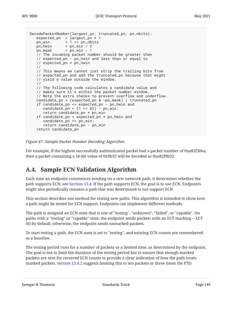
For example, if the highest successfully authenticated packet had a packet number of 0xa82f30ea,then a packet containing a 16-bit value of 0x9b32 will be decoded as 0xa82f9b32.
Figure 47: Sample Packet Number Decoding Algorithm
DecodePacketNumber(largest_pn, truncated_pn, pn_nbits): expected_pn = largest_pn + 1 pn_win = 1 << pn_nbits pn_hwin = pn_win / 2 pn_mask = pn_win - 1 // The incoming packet number should be greater than // expected_pn - pn_hwin and less than or equal to // expected_pn + pn_hwin // // This means we cannot just strip the trailing bits from // expected_pn and add the truncated_pn because that might // yield a value outside the window. // // The following code calculates a candidate value and // makes sure it's within the packet number window. // Note the extra checks to prevent overflow and underflow. candidate_pn = (expected_pn & ~pn_mask) | truncated_pn if candidate_pn <= expected_pn - pn_hwin and candidate_pn < (1 << 62) - pn_win: return candidate_pn + pn_win if candidate_pn > expected_pn + pn_hwin and candidate_pn >= pn_win: return candidate_pn - pn_win return candidate_pn
A.4. Sample ECN Validation Algorithm Each time an endpoint commences sending on a new network path, it determines whether thepath supports ECN; see Section 13.4. If the path supports ECN, the goal is to use ECN. Endpointsmight also periodically reassess a path that was determined to not support ECN.
This section describes one method for testing new paths. This algorithm is intended to show howa path might be tested for ECN support. Endpoints can implement different methods.
The path is assigned an ECN state that is one of "testing", "unknown", "failed", or "capable". Onpaths with a "testing" or "capable" state, the endpoint sends packets with an ECT marking -- ECT(0) by default; otherwise, the endpoint sends unmarked packets.
To start testing a path, the ECN state is set to "testing", and existing ECN counts are rememberedas a baseline.
The testing period runs for a number of packets or a limited time, as determined by the endpoint.The goal is not to limit the duration of the testing period but to ensure that enough markedpackets are sent for received ECN counts to provide a clear indication of how the path treatsmarked packets. Section 13.4.2 suggests limiting this to ten packets or three times the PTO.
RFC 9000 QUIC Transport Protocol May 2021
Iyengar & Thomson Standards Track Page 149

After the testing period ends, the ECN state for the path becomes "unknown". From the"unknown" state, successful validation of the ECN counts in an ACK frame (see Section 13.4.2.1)causes the ECN state for the path to become "capable", unless no marked packet has beenacknowledged.
If validation of ECN counts fails at any time, the ECN state for the affected path becomes "failed".An endpoint can also mark the ECN state for a path as "failed" if marked packets are all declaredlost or if they are all ECN-CE marked.
Following this algorithm ensures that ECN is rarely disabled for paths that properly support ECN.Any path that incorrectly modifies markings will cause ECN to be disabled. For those rare caseswhere marked packets are discarded by the path, the short duration of the testing period limitsthe number of losses incurred.
Contributors The original design and rationale behind this protocol draw significantly from work by
.
The IETF QUIC Working Group received an enormous amount of support from many people. Thefollowing people provided substantive contributions to this document:
JimRoskind [EARLY-DESIGN]
• Alessandro Ghedini• Alyssa Wilk• Antoine Delignat-Lavaud• Brian Trammell• Christian Huitema• Colin Perkins• David Schinazi• Dmitri Tikhonov• Eric Kinnear• Eric Rescorla• Gorry Fairhurst• Ian Swett• Igor Lubashev• ( )奥 一穂 Kazuho Oku• Lars Eggert• Lucas Pardue• Magnus Westerlund• Marten Seemann• Martin Duke• Mike Bishop• Mikkel Fahnøe Jørgensen
RFC 9000 QUIC Transport Protocol May 2021
Iyengar & Thomson Standards Track Page 150

• Mirja Kühlewind• Nick Banks• Nick Harper• Patrick McManus• Roberto Peon• Ryan Hamilton• Subodh Iyengar• Tatsuhiro Tsujikawa• Ted Hardie• Tom Jones• Victor Vasiliev
Authors' Addresses Jana Iyengar ( )������Fastly
[email protected] Email:
Martin Thomson ( )������Mozilla
[email protected] Email:
RFC 9000 QUIC Transport Protocol May 2021
Iyengar & Thomson Standards Track Page 151