rgd5000 generator service manual - voice … se… · model rgd5000 jype brushless, self exciting,...
TRANSCRIPT

MAN,UAL Model
RGD5000 Generator
PUB-GS1187 Rev. 8198

. CONTENTS
*-
”
section nt/e Page 1 . SPECIFICATIONS ....................................................................................................... 1
2 . PERFOMANCE CURVES ........................................................................................... 2
2-1 MODEL RGD5000 .................................................................................................. 2 2-2 DC OUTPUT ......................................................................................................... 2
3 . FEATURES .................................................................................................................. 3
4 . GENERAL DESCRIPTION .......................................................................................... 4 4-1 EXTERNAL VIEW ................................................................................................. 4 4-2 CONTROL PANEL ................................................................................................ 5 4-3 LOCATION of SERIAL NUMBER and SPECIFICATION NUMBER ...................... 6
5 . CONSTRUCTION AND FUNCTION ........................................................................... 7
5-1 CONSTRUCTION ................................................................................................. 7 5-2 FUNCTION ............................................................................................................ 7 5-3 GENERATOR OPERATION ................................................................................ 11
6 . SAFETY PRECAUTIONS ......................................................................................... 14
7 . RANGE OF APPLICATIONS .................................................................................... 15 8 . MEASURING PROCEDURES .................................................................................. 18
8-1 MEASURING INSTRUMENTS ........................................................................... 18 8-2 AC OUTPUT MEASURING ................................................................................. 21 8-3 DC OUTPUT MEASURING ................................................................................. 21 8-4 MEASURING INSULATION RESISTANCE ........................................................ 22
9 . CHECKING FUNCTIONAL MEMBERS .................................................................... 24 9-1 VOLTMETER ....................................................................................................... 24 9-2 AC RECEPTACLES ............................................................................................ 24 9-3 NO-FUSE BREAKER ........................................................................................... 24 9-4 STATOR .............................................................................................................. 25 9-5 ROTOR ASSEMBLY ........................................................................................... 26 9-6 CONDENSER ..................................................................................................... 27 9-7 DIODE RECTIFIER ............................................................................................. 27
10 . DISASSEMBLY AND ASSEMBLY .......................................................................... 29 10-1 PREPARATION and PRECAUTIONS ............................................................... 29 10-2 SPECIAL TOOLS for DISASSEMBLY and ASSEMBLY .................................... 29
Section Tile paw 10-3 DISASSEMBLY PROCEDURES ....................................................................... 30 10-4 ASSEMBLY PROCEDURES ............................................................................. 39 10-5 CHECKING. DISASSEMBLY and REASSEMBLY of the CONTROL BOX ....... 50
11 . TROUBLESHOOTING ............................................................................................ 52 11 -1 NO AC OUTPUT ................................................................................................ 52 11-2 AC VOLTAGE IS TOO THIGH OR TOO LOW ................................................... 54 11-3 AC VOLTAGE IS NORMALAT NO-LOAD. BUTTHE LOAD CANNOT BE APPLIED ..... 55 11-4 NO DC OUTPUT ............................................................................................... 56
12 . WIRING DIAGRAM ................................................................................................. 57

Model RGD5000
JYPe Brushless, Self Exciting, 2-Pole, Single Phase
Frequency
4500 W Rated Output AC
5000 W Maximum Output
60 Hz
120 v 37.5 A
12OV/24OV
I Current I 37.5N18.814
I I I
Power Factor
Voltage Regulator I Condenser Type
12 V-8.3 A (100 W) DC Output
1 .o
Air-Cooled 4-Cycle, Diesel Engine
a 5 g ! 5 1 a
1 [I W
1
-
t c
1
Dimensions (L x W x H)
Dry Weight 95 kg (209 Ibs.) I 26.5 x 19.7 x 21.3 in (675 x 500 x 542 mm)
Electric starter motor is available as option.
Model
8.5 HP / 3600 rpm Rated Output
412 cm3 (25.14 cu. in.) Displacement
DY41 D
~
Fuel ~~ ~ ~~
Diesel light oil
Fuel Tank Capacity ~~~ ~ ~
4.2 U.S. gal. (16.0 liters)
Rated Coutinuous Operation 1 1 2.0 hours I Oil Capacity
Starting System i Recoil Starter and Electric Starter
2.3 US. gal. (1.1 liters)
- 1 -

2. PERFOMANCE CURVES
2-1 MODEL RGD5000
t -63
62
61
P
zi E
- *
= 6 0 Y K 59
1 130 s: 120 - g 110 2
h
3
0 10 20 30 40 50
5k
4k t - 2k 2 c
3 c
l k 0
0
CURRENTO -
2-2 DC OUTPUT
- = I 6 Lu 14
12 g I O
0 2 4 6 8 1 0 CURRENT(A) -
Output Max. ................. 5000 W Output Rated ............... 4500 W Frequency .................... 60 Hz Voltage ......................... 120 V
Output Max. .............. 5000 W Output Rated ............ 4500 W Frequency ................. 60 Hz Voltage ...................... 120 Vl24OV
DC Voltage .................. 12 V
DC Ampere ................. 8.3 A
DC output .................... 100 W
The voltage cuwe shown in the left indicates the char- acteristic of DC output when charging a battery. The voltage may be decreased by 20% when the resis- tance load is applied.
NOTE : It is possible to use both DC and AC outputs simultaneously up to the rated output in total. *
- 2 -

3.FEATURES
3-1 BRUSHLESS ALTERNATOR
Newly developed brushless alternator eliminates troublesome brush maintenance.
3-2 EASY STARTING
Light pull recoil starter accompanied with automatic decompression system makes the new RGD series generators even easier in starting than gasoline engine generators.
3-3 QUIET OPERATION
The new RGD series generator provides quiet operation by means of: The superb design of intake-exhaust system. Direct injection combustion system.
0 A large super silent muffler. An efficient low noise air cleaner.
3-4 ECONOMICAL PERFORMANCE
On top of well known diesel economy, the air-cooled Robin diesel engine features direct fuel injection and special design refinements for extra fuel efficiency.
3-5 OIL SENSOR The OIL SENSOR automatically shuts the engine off whenever the oil level f& down below a safe level preventing engine seizure.
3-6 COMPACT, LIGHT WEIGHT
The combination of newly developed brushless alternator and air-cooled single cylinder Robin diesel engine enables the new RGD series generators to be very compact in size and light in weight.
3-7 RELIABLE PERFORMANCE WITH MINIMAL MAINTENANCE
A brushless alternator eliminates troublesome brush maintenance. A dripproof alternator design. A trouble free condenser voltage regulator. A fuseless circuit breaker. A dust-proof oil-bath air cleaner. The OIL SENSOR automatically shuts the engine off whenever the oil level falls down below a safe level preventing engine seizure.
3-8 LONG-LIFE DURABILITY
0 Compact and smooth running air-cooled Robin diesel engine lasts much longer than the gasoline
0 Trouble-free brushless alternator with condenser type voltage regulator works all the year round engine of the same size.
without any maintenace work.
- 3-

4.GENERAL DESCRIPTION
4-1 EXTERNAL VIEW
Rocket cover Air cleaner \ ACreceptack \
Fuel gauge Tank cap
\ /
Muffler
- 4 -

4-2 CONTROL PANEL
RGD5000 : 60HZ-l20V, 60Hz-l2OV/240V TYPE
Voltmeter Full power switch
AC
Earth terminal DC output terminal
- 5 -
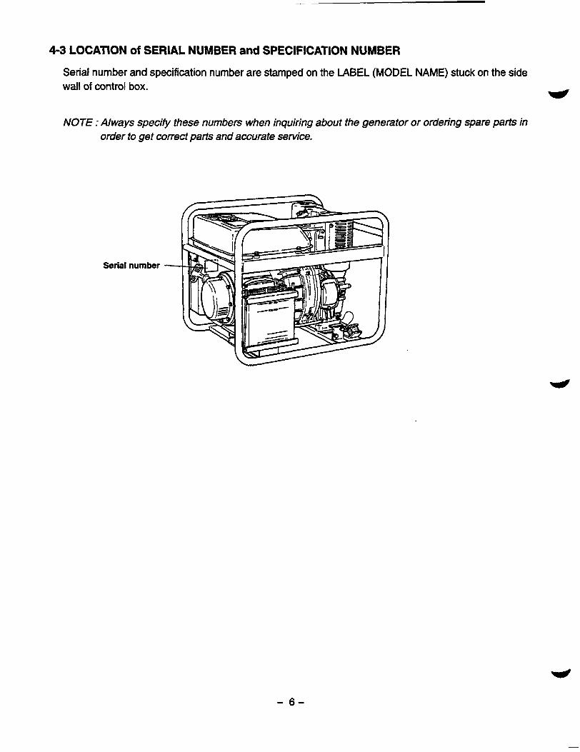
4-3 LOCATION of SERIAL NUMBER and SPECIFICATION NUMBER
Serial number and specification number are stamped on the LABEL (MODEL NAME) stuck on the side wall of control box. e NOTE : Always specify these numbers when inquiring about the generator or ordering spare parts in
order to get correct parts and accurate service.
Serial number
- 6 -
"
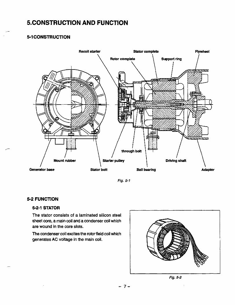
5CONSTRUCTION AND FUNCTION
!j-lCONSTRUCTlON
Mount rubber \ Starter pu"ey Driving shaft \
Generator base Stator bolt Bal l bearing Adapter
Fig. 5-1
5-2 FUNCTION
5-2-1 STATOR
The stator consists of a laminated silicon steel I sheet core, a main c o i l and a condenser coil which are wound in the core slots.
The condenser coil excites the rotor field coil which generates AC voltage in the main coil.
Fig. 5-2
- 7 -

5-2-2 CONDENSER
One or two condensers are installed in the con- trol box and are connected to the condenser coil of the stator.
These condensers and condenser coil regulate the output voltage.
5-2-3 ROTOR
The rotor consists of a laminated silicon s t e e l sheet core and a field coil which is wound over the core.
DC current in the field coil magnetizes the steel sheet core. Two permanent magnets are provided for the primary exciting action.
Fig. 5-4
A diode rectifier and surge absorber is mounted inside of the insulator.
Fig. 5-5A
- 8 -
Fig. 5-5B
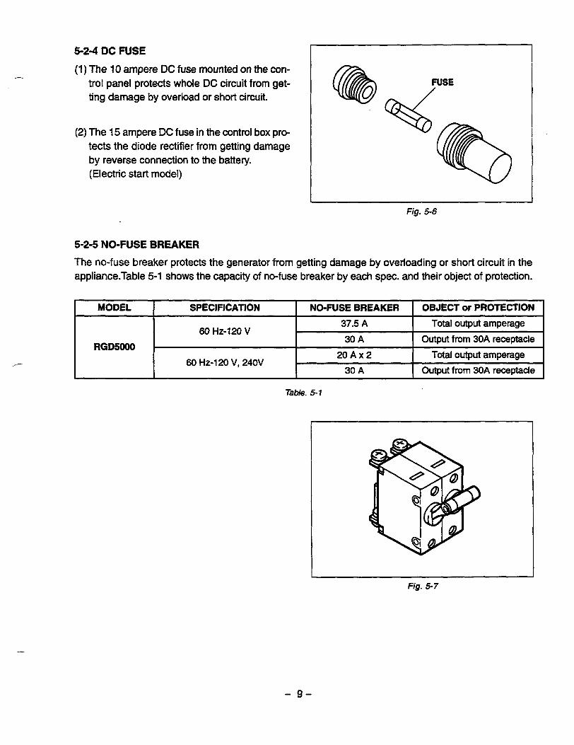
5-24 DC FUSE
(1) The 10 ampere DC fuse mounted on the con- trol panel protects whole DC circuit from get- ting damage by overload or short circuit.
(2) The 15 ampere DC fuse in the control box pro- tects the diode rectifier from getting damage by reverse connection to the battery. (Electric start model)
5-2-5 NO-FUSE BREAKER
L
Fig. 5-6
The no-fuse breaker protects the generator from getting damage by overloading or short circuit in the appliance.Table 5-1 shows the capacity of no-fuse breaker by each spec. and their object of protection.
/-
MODEL OBJECT or PROTECTION NO-FUSE BREAKER SPECIFICATION
60 HZ-120 V 37.5 A Total output amperage
RGD5000 30 A Output from 30A receptacle
2 0 A x 2 Total output amperage 60 HZ-120 V, 240V
30 A Output from 3OA receptacle
Table. 5-1
Fig. 5-7
- 9 -
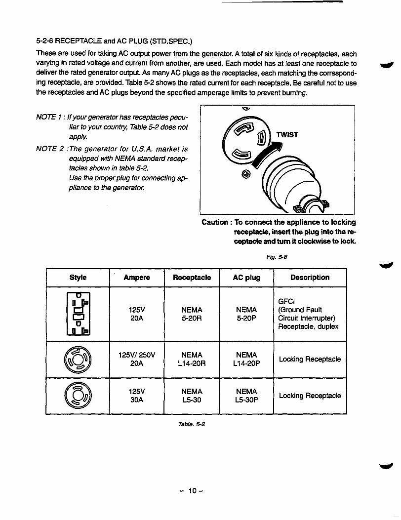
5-2-6 RECEPTACLE and AC PLUG (STD.SPEC.)
These are used for taking AC output power from the generator. A total of six kinds of receptacles, each varying in rated voltage and current from another, are used. Each model has at least one receptacle to deliver the rated generator output. As many AC plugs as the receptacles, each matching the correspond- ing receptacle, are provided. Table 5-2 shows the rated current for each receptacle. Be careful not to use the receptacles and AC plugs beyond the specified amperage limits to prevent burning.
w
NOTE 1 : If your generator has receptacles pecu- liar to your country, Table 5-2 does not apply.
NOTE 2 :The generator for U.S.A. market is equipped with NEMA standard recep- tacles shown in table 5-2. Use the proper plug for connecting ap- pliance to the generafoE
I ' W
Caution : To connect the appliance to locking receptacle, insert the plug into the r e ceptacle and turn it clockwise to lock
Fig. 5-8
style Description AC plug Receptacle Ampere
El 30A @ 20A @
20A
GFCI 125V (Ground Fault NEMA NEMA
5-20R Circuit Interrupter) 5-20P Receptacle, duplex
125V/ 250V NEMA L14-20R L14-20P
NEMA Locking Receptacle
125V NEMA E-30 L5-30P
NEMA Locking Receptacle
Table. 5-2
- 10-

PERMANENT MAGNET STATOR FOR INITIAL EXCITATION ,-
FIELD COIL I
APPLIANCE
"""I
"""",I
fig, 5-9
5-3-1GENERATlON Of NO-LOAD VOLTAGE
(1) When the generator starts running, the permanent magnet built-in to the rotor generates 3 to 6V of AC voltage inthe main coil and condenser coil wound on the stator.
(2) As one or two condensers are connected to the condenser coil, the small voltage at the condenser coil generates a minute current @I which flows through the condenser coil. At this time, a small flux is produced with which the magnetic force at the rotor's magnetic pole is intensified.When this mag- netic force is intensified, the respective voltages in the main coil and condenser coil rise up. As the current @$ increases, the magnetic flux at the rotor's magnetic pole increases further. Thus the volt- ages at the main coil and condenser coil keep rising by repeating this process.
(3) As AC current flows through the condenser coil, the density of magnetic flux in the rotor changes. This change of magnetic flux induces AC voltage in the field coil, and the diode rectifier in the field coil circuit rectifies this AC voltage into DC. Thus a DC current @ flows through the field coil and magne- tizes the rotor core to generate an output voltage in the main coil.
(4) When generator speed reaches 3000 to 3300 rpm, the current in the condenser coil and field coil increases rapidly. This acts to stabilize the output voltage of each coils. If generator speed further increases to the rated value, the generator output voltage will reach to the rated value.
5-3-2 VOLTAGE FLUCTUATIONS UNDER LOAD When the output current @ flows through the main coil to the appliance, a magnetic flux is produced and serves to increase current @I in the condenser coil. When current a increases, the density of magnetic flux across the rotor core rises. As a result, the current flowing in the field coil increases and the genera- tor output voltage is prevented from decreasing.
- 11 -
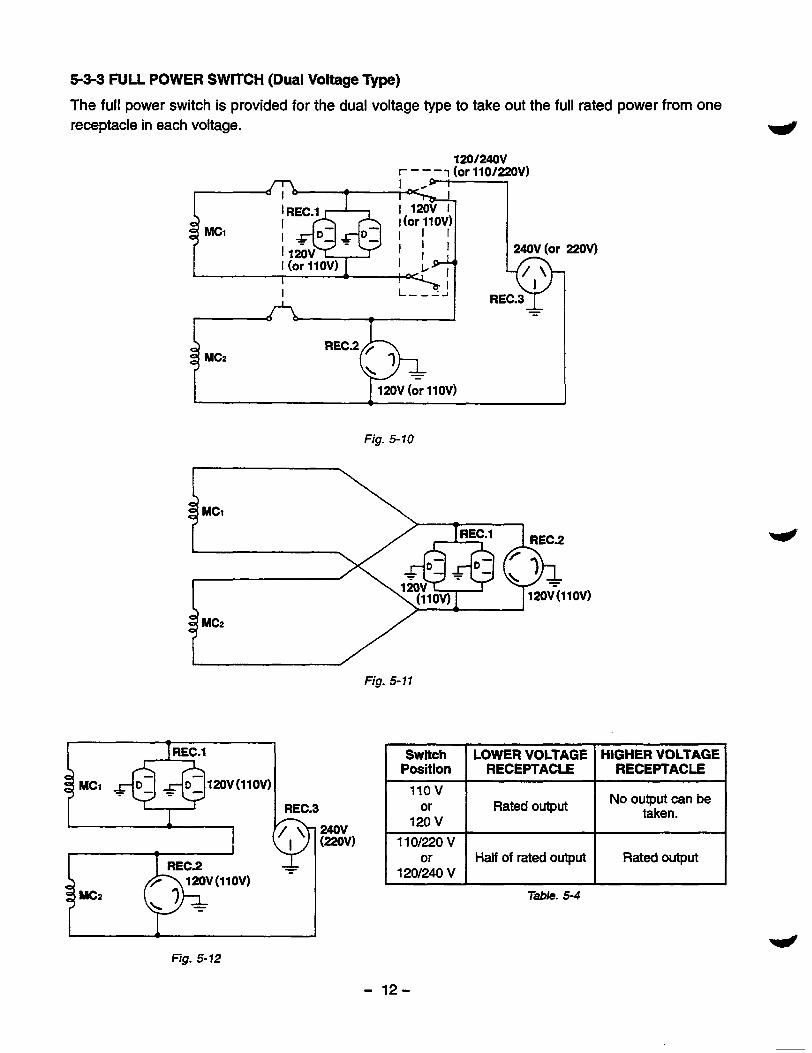
5-34 FULL POWER SWITCH (Dual Voltage Type)
The full power switch is provided for the dual voltage type to take out the full rated power from one receptacle in each voltage.
I
Fig. 5-10
L \
3 MCz
Fig. 5-11
/
w
Switch RECEPTACLE RECEPTACLE Position
HIGHER VOLTAGE LOWER VOLTAGE
110 v 1 lgv I Rated output No output can be taken.
1 1 o m 0 v
120/240 v or Rated output Half of rated output
Table. 5 4
- 12 -
.-
Two main coils are wound over stator core. Each main coil outputs half the rated power at the lower voltage (11OV or 120V). These main coils are wound to be in the same phase. The full power switch reconnects these main coils in parallel or in series.
Fig. 5-10 shows a circuit diagram. When the full power switch is set for single lower voltage indication (11 OV or 120V), the switch position is as indicated by the lower solid line in the diagram. Fig. 5-11 is a simplified representation of this circuit, showing the two main coils connected in parallel.ln this case, the higher voltage (220V or 240V) at Rec. 3 cannot be taken out. Rec. 2 for the lower voltage can output up to the rated power (up to 30A if the rated current is over 30A), and Rec. 1 can output up to a total of 15A.
When the full power switch is set for double voltage indication (11OV/22OV or 120V/240V), the switch position is as indicated by the upper dotted line in Fig. 5-1 0. Fig. 5-1 2 is a simplified representation of this circuit, showing the two main coils connected in series. In this case, power can be taken simultaneously from the receptacles for the both voltages. Rec. 3 for the higher voltage can output up to the rated power, but Rec. 1 and Rec. 2 for the lower voltage can output only up to half the rated power each.
Table 5-4 is a summary of the above explanation. Select the proper output voltage by full power switch in accordance with the appliance to be used.
- 13-
6. SAFETY PRECAUTIONS
1. Use extreme caution near fuel. A constant danger of explosion or fire exists. w Do not fill the fuel tank while the engine is running. Do not smoke or use opern flame near the fuel tank. Be careful not to spill fuel when refueling. If spilt, wipe it and let dry before starting the engine.
2. Do not place inflammable materials near the generator.
Be careful not to put fuel, matches, gunpowder, oily cloth, straw, and any other inflammables near the generator.
3. Do not operate the generator in a room,cave or tunnel. Always operate in a well-ventilated area.
Otherwise the engine may overheat and also, the poisonous carbon monoxide contained in the ex- haust gases will endanger human lives. Keep the generator at least 1 m (4 feet) away from structures or facilities during use.
4.0perate the generator on a level surface.
If the generator is tilted or moved during use, there is a danger of fuel spillage and a chance that the generator may tip over.
5. Do not operate with wet hands or in the rain.
Severe electric shock may occur. If the generator is wet by rain or snow, wipe it and thoroughly dry it before starting. Don’ t pour water over the generator directly nor wash it with water. If the generator is wet with water, the insulations will be adversely affected and may cause current leakage and electric shock.
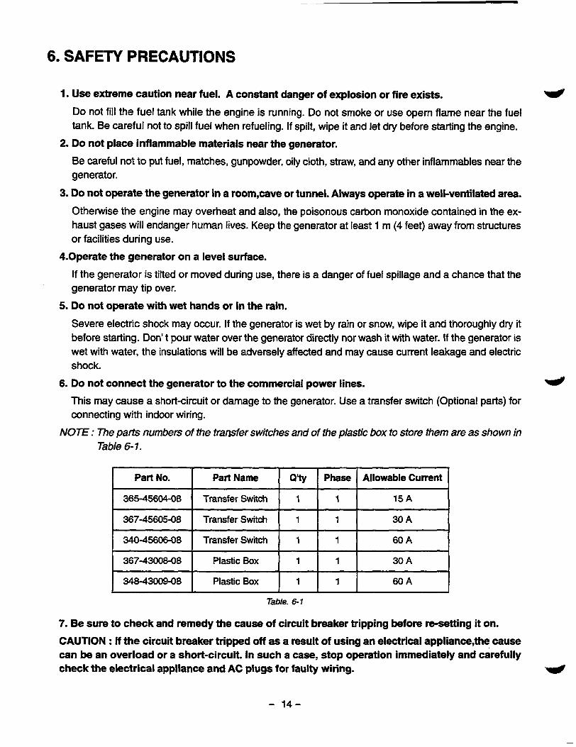
6. Do not connect the generator to the commercial power lines. 4 This may cause a short-circuit or damage to the generator. Use a transfer switch (Optional parts) for connecting with indoor wiring.
NOTE : The parts numbers of the trawfer switches and of the plastic box to store them are as shown in Table 6-1.
Part No. Allowable Current Phase Qlty Part Name
365-45604-08 15 A 1 1 Transfer Switch
367-45605-08
60 A 1 1 Transfer Switch 340-45606-08
30 A 1 1 Transfer Switch
367-43008-08
60 A 1 1 Plastic Box 34843009-08
30 A 1 1 Plastic Box
Table. 6 1
7. Be sure to check and remedy the cause of circuit breaker tripping before re-setting it on.
CAUTION : If the circuit breaker tripped off as a result of using an electrical appliance,the cause can be an overload or a short-circuit. In such a case, stop operation immediately and carefully check the electrical appliance and AC plugs for faulty wiring.
- 14-
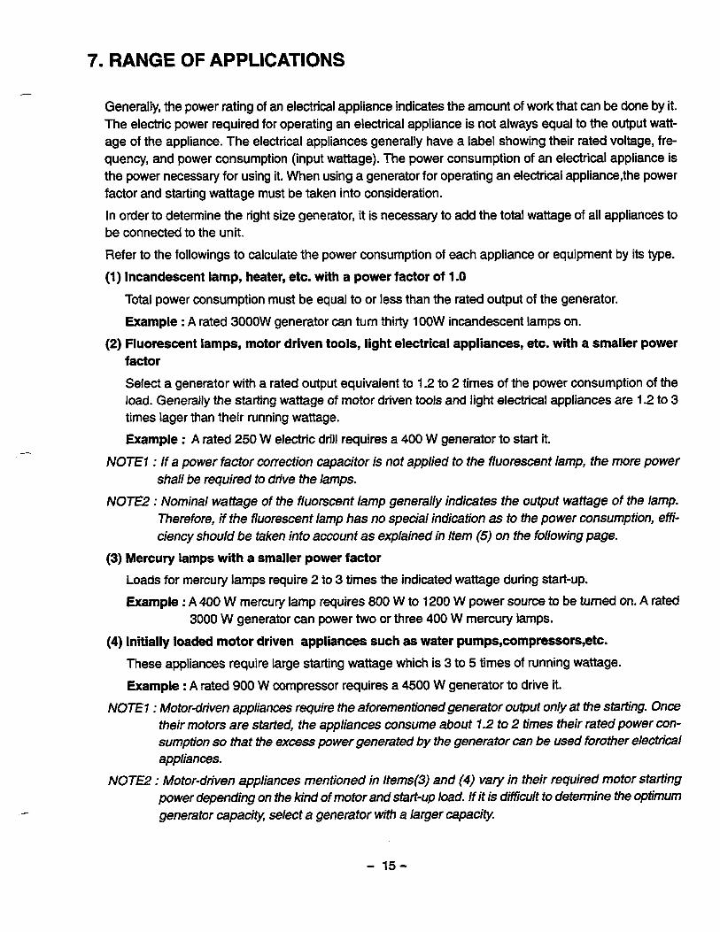
Generally, the power rating of an electrical appliance indicates the amount of work that can be done by it. The electric power required for operating an electrical appliance is not always equal to the output watt- age of the appliance. The electrical appliances generally have a label showing their rated voltage, fre- quency, and power consumption (input wattage). The power consumption of an electrical appliance is the power necessary for using it. When using a generator for operating an electrical appliance,the power factor and starting wattage must be taken into consideration.
In order to determine the right size generator, it is necessary to add the total wattage of all appliances to be connected to the unit.
Refer to the followings to calculate the power consumption of each appliance or equipment by its type.
(1) Incandescent lamp, heater, etc. with a power factor of 1 .O
Total power consumption must be equal to or less than the rated output of the generator.
Example : A rated 3000W generator can turn thirty 1OOW incandescent lamps on.
factor Select a generator with a rated output equivalent to 1.2 to 2 times of the power consumption of the load. Generally the starting wattage of motor driven tools and light electrical appliances are 1.2 to 3 times lager than their running wattage.
Example : A rated 250 W electric drill requires a 400 W generator to start it.
(2) Fluorescent lamps, motor driven tools, light electrical appliances, etc. with a smaller power
NOTE7 : If a power factor correction capacitor is not applied to the fluorescent lamp, the more power shall be required to drive the lamps.
NOTE2 : Nominal wattage of the fluorscent lamp generally indicates the output wattage of the lamp. Therefore, if the fluorescent lamp has no special indication as to the power consumption, effi- ciency should be taken into account as explained in Item (5) on the following page.
(3) Mercury lamps with a smaller power factor Loads for mercury lamps require 2 to 3 times the indicated wattage during start-up.
Example : A 400 W mercury lamp requires 800 W to 1200 W power source to be turned on. A rated 3000 W generator can power two or three 400 W mercury lamps.
(4) Initially loaded motor driven appliances such as water pumps,compressors,etc. These appliances require large starting wattage which is 3 to 5 times of running wattage.
Example : A rated 900 W compressor requires a 4500 W generator to driie it.
NOTE7 : Motor-driven appliances require the aforementioned generator output only at the starting. Once their motors are started, the appliances wnsume about 7.2 to 2 times their rated power con- sumption so that the excess power generated by the generator can be used forother electrical appliances.
NOTE2 : Motor-driven appliances mentioned in Items(3) and (4) vary in their required motor starting power depending on the kind of motor and start-up load. If it is difficult to determine the Optimum generator capacw, select a generator with a larger capacity
- 15-

(5) Appliances without any indication as to power consumption
Some appliances have no indication as to power consumption; but instead the work load (output) is indicated. In such a case, power consumption is to be worked out according to the numerical formula U P mentioned below.
(Output of electrical appliance)
(Efficiency) = (Power consumpition)
Efficiencies of some electrical appliances are as follows : Single-phase motor ................................ 0.6 to 0.75 The smaller the motor, the
Three-phase motor ................................ 0.65 to 0.9 lower the efficiency.
Fluorescent lamp ................................... 0.7 to 0.8
Example 1: A 40W fluorescent lamp means that its luminous output is 40W. Its efficiency is 0.7 and accordingly, power consumption will be 40 f 0.7= 57W. As explained in Item (2), multiply this power consumption value of 57 W by 1.2 to 2 and you will get the figure of the neces- sary capacity of a generator. In other words, a generator with a rated output of 1 OOOWcapacity can light nine to fourteen 40 W fluorescent lamps.
Example 2 : Generally speaking, a 400 W motor means that its work load is 400 W. Efficiency of this motor is 0.7 and power consumption will be 400+0.7= 570 W. When this motor is used for a motor-driven tool, the capacity of the generator should be multiple of 570 W by 1.2 to 3 as explained in the Item (3). 570 (W) x 1.2 to 3 = 684 (W) to 171 0 (W)
MODEL RGD5000
Frequency 60 Hz
lncandesent lamp, heater, etc. 4500 w
Fluorescent lamp, Motor- driven tool, general-porpose I approx.
3000 W
I Mercury lamp, etc. approx. 2700 W
I I Pump, compressor, etc.
Table. 7-1
- 16-
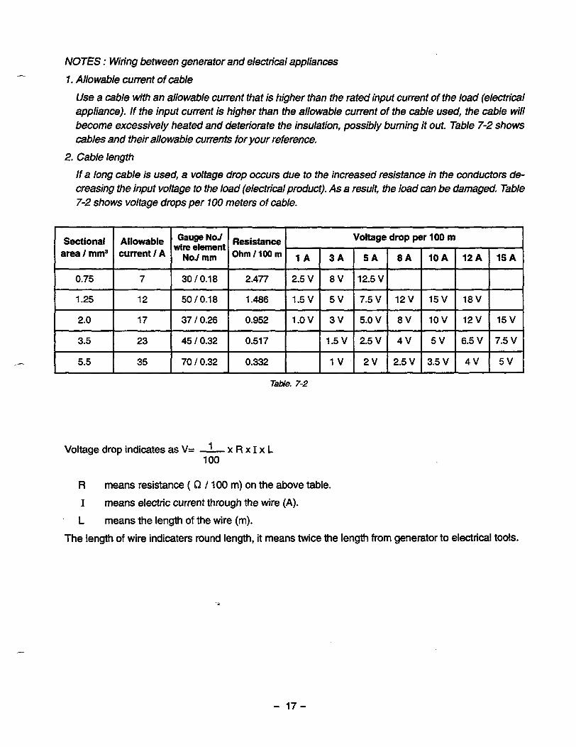
NOTES : Wring between generator and electrical appliances
I . Allowable current of cable
Use a cable W h an allowable current that is higher than the rated input current of the load (electrical appliance). If the input current is higher than the allowable current of the cable used, the cable will become excessively heated and deteriorate the insulation, possibly burning it out. Table 7-2 shows cables and their allowable currents for your reference.
2. Cable length
If a long cable is used, a voltage drop occurs due to the increased resistance in the conductors de- creasing the input voltage to the load (electrical product). As a result, the load can be damaged. Table 7-2 shows voltage drops per 100 meters of cable.
Sectional area I mm3
I- I 5.5
Allowable current I A
7
12
17
23
35
No’ wire element
NoJ mm Resistance
30 10.18
50 I 0.1 8 1.486
37 I 0.26
0.517
70 I 0.32 0.332
Table. 7-2
Voltage drop indicates as V= - x R x I x L 1 100
R means resistance ( 62 / 100 m) on the above table.
I means electric current through the wire (A).
L means the length of the wire (m).
The length of wire indicaters round length, it means twice the length from generator to electrical tools.
- 17-
8. MEASURING PROCEDURES
8-1 MEASURING INSTRUMENTS
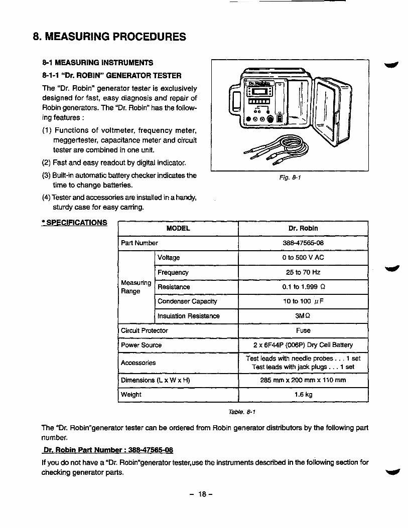
8-1-1 “Dr. ROBIN” GENERATOR TESTER
The “Dr. Robin” generator tester is exclusively designed for fast, easy diagnosis and repair of Robin generators. The “Dr. Robin” has the follow- ing features :
(1) Functions of voltmeter, frequency meter, meggertester, capacitance meter and circuit tester are combined in one unit.
(2) Fast and easy readout by digital indicator.
(3) Built-in automatic battery checker indicates the time to change batteries.
sturdy case for easy carring. (4) Tester and accessories are installed in a handy,
SPECIFICATIONS
w Fig. 8-1
MODEL Dr. Robin
Part Number 388-47565-08
Voltage Oto500VAC
1 25 to 70 Hz ~ ~~ ~
Measuring Range
Resistance 0.1 to 1.999 Q
I Condenser Capacity I 10to100 p F
Power Source 2 x 6F44P (006P) Dry C e l l Battery
Accessories
Dimensions (L x W x H) 285 mm x 200 mm x 110 mm
Weight 1.6 kg
Test leads with needle probes . . . 1 set Test leads with jack plugs . . , 1 set
Table. 8-1
The “Dr. Robinngenerator tester can be ordered from Robin generator distributors by the following part number.
Dr. Robin Part Number : 38847565-08
If you do not have a “Dr. Robinngenerator tester,use the instruments described in the following section for checking generator parts.
- 18-
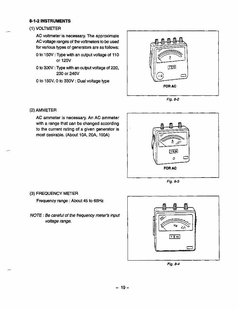
8-1-2 INSTRUMENTS
(1 ) VOLTMETER
AC voltmeter is necessary. The approximate AC voltage ranges of the voltmeters to be used for various types of generators are as follows:
0 to 150V : Type with an output voltage of 11 0
0 to 300V : Type with an output voltage of 220,
0 to 15OV, 0 to 330V : Dual voltage type
or 120V
230 or 240V
(2) AMMETER
AC ammeter is necessary. An AC ammeter with a range that can be changed according to the current rating of a given generator is most desirable. (About 10A, 20A, 1OOA)
(3) FREQUENCY METER
Frequency range : About 45 to 65Hz
NOTE : Be careful of the frequency meter's input voltage range.
FOR AC
L
Fig. 8-2
FQR AC
Fig. 8-3
"
Fig. 8-4
- 19-

(4) CIRCUITTESTER
Used for measuring resistance, etc.
(5) MEGGER TESTER
Used for measuring generator insulation re- sistance. Select one with testing voltage range of 500V.
(6) TACHOMETER
Use the contactless type tacho meter.
I
Fig. 8-6
I Fig. 8-7
- 20-
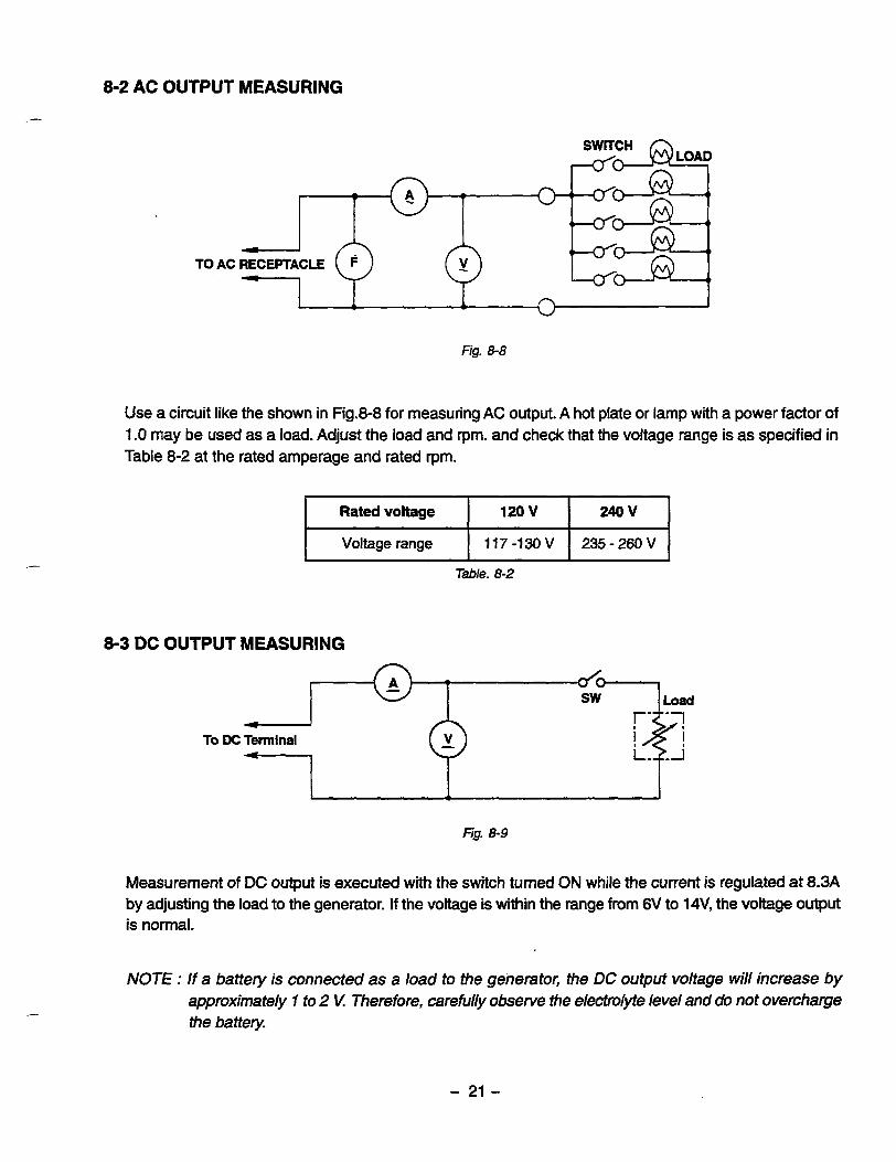
8-2 AC OUTPUT MEASURING
I d
TO AC RECEPTACLE
I c 1 1 n
U I
Fig. 8-8
Use a circuit like the shown in Fig.8-8 for measuring AC output. A hot plate or lamp with a power factor of 1.0 may be used as a load. Adjust the load and rpm. and check that the voltage range is as specified in Table 8-2 at the rated amperage and rated rpm.
Rated voltage
235 - 260 V 117 -130 V Voltage range
240 v 120 v
Table. 8-2
8-3 DC OUTPUT MEASURING
" To DC Terminal
Fig. 8-9
Measurement of DC output is executed with the switch turned ON while the current is regulated at 8.3A by adjusting the load to the generator. If the voltage is within the range from 6V to 14V, the voltage output is normal.
NOTE : I f a battery is connected as a load to the generator, the DC output voltage will increase by approximately 7 to 2 V: Therefore, careful& observe the electrolyte level and do not overcharge the battery
- 21 -

8 4 MEASURING INSULATION RESISTANCE
Use a "Dr. Robinngenerator tester in megger tester mode or use a megger tester to check the insula- tion resistance. Connect a megger tester to one of receptacle output terminals and the ground ter- minal, then measure the insulation resistance. An insulation resistance of 1 megohm or more is nor- mal. (The original insulation resistance at the time of shipment from the factory is 10 megohm or more.) If it is less than 1 megohm, disassemble the generator and measure the insulation resis- tance of the stator, rotor and control panel indi- vidually.
* STATOR
(1) Measure the insulation resistance between BLUE lead and the core.
(2) Measure the insulation resistance between WHITE lead and the core.
(3) Measure the insulation resistance between YELLOW lead and the core.
(4) Measure the insulation resistance between BROWN lead and the core.
ROTOR
Measure the insulation across one of the soldered terminals of the rotor andthe core.
I I
i U'
i
Fig. 8-11
~
Fig. 8-12
- 22-

CONTROL PANEL Measure the insulation resistances between the live parts and the grounded parts.
=4 I
fig. 8-13
Any part where the insulation resistance is less than 1 MQ has faulty insulation, and may cause electric leakage and electric shock.
Replace the faulty part.
- 23-
9.CHECKING FUNCTIONAL MEMBERS
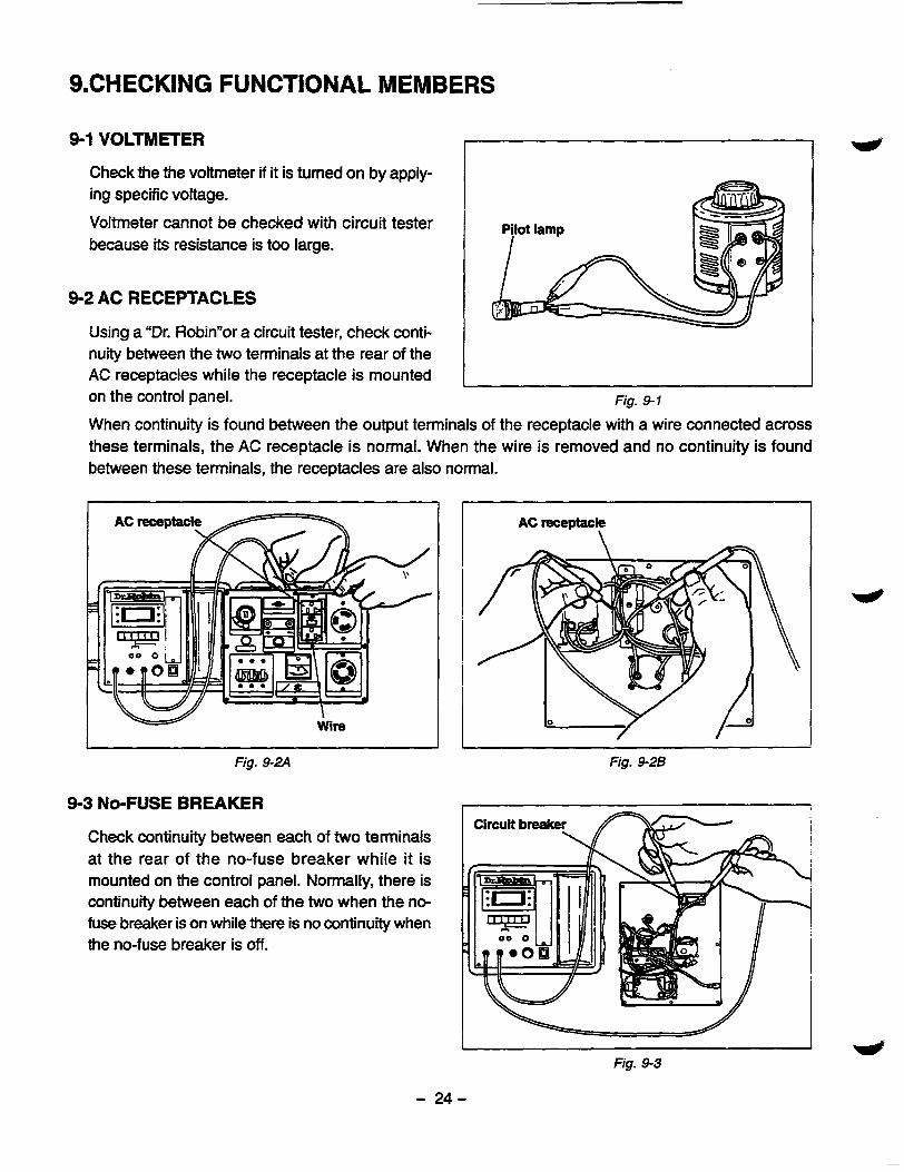
9-1 VOLTMETER
Check the the voltmeter if it is turned on by apply- ing specific voltage.
Voltmeter cannot be checked with circuit tester because its resistance is too large.
9-2 AC RECEPTACLES
Using a "Dr. Robinnor a circuit tester, check conti- nuity between the two terminals at the rear of the AC receptacles while the receptacle is mounted on the control panel. Fig. 9-1
When continuity is found between the output terminals of the receptacle with a wire connected across these terminals, the AC receptacle is normal. When the wire is removed and no continuity is found between these terminals, the receptacles are also normal.
I W I
Wire
AC receptacle \
Fig. 9-2A Fig. 9-26
9-3 NO-FUSE BREAKER I
Circuit breake Check continuity between each of two terminals at the rear of the no-fuse breaker while it is mounted on the control panel. Normally, there is continuity between each of the two when the no- fuse breaker is on while there is no continuity when the no-fuse breaker is off.
Fig. 9-3
- 24-
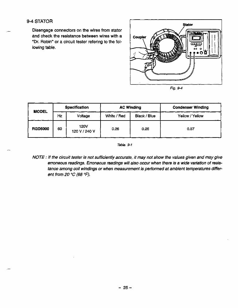
9-4 STATOR i I Disengage connectors on the wires from stator and check the resistance between wires with a "Dr. Robin" or a circuit tester refering to the fol- lowing table.
u Fig. 9-4
Specification Condenser Winding AC Winding MODEL
Hz Yellow / Yellow Black / Blue White / Red Voltage
120v RGD5000 120 V / 240 V 6o 0.26 0.57 0.26
Tale. 9-1
NOTE : If the circuit tester is not sufficiently accurate, it may not show the values given and may give erroneous readings. Erroneous readings will also occur when there is a wide variation of resis- tance among coil windings or when measurement is performed at ambienf.temperafures differ- ent from 20 OC (68 OF).
- 25-

9-5 ROTOR ASSEMBLY
(1 ) Using a "Dr. Robin" Or a Circuit tester, measure the resistance of the field coil at the terminals.
( Q )
MODEL RGD5000
RESISTANCE 1.6 Q
Tble. 9-2 NOTE 7 :
Because a diode is soldered to the coil ends at the terminals, resistance may be measured only when tester probes touche the terminals in one combination of polarity merefore, if no resisfance reading appears, try cbecking in reverse polarity.
NOTE 2 : If the circuit tester is not sufficiently accurate, it may not show the values given and may give er- roneous readings. Erroneous reading will also occur when there is a wide variation of resistance among coil windings or when measurement is petformed at embient temperatures dfierent from 20 "C (68 OF).
(2) Check if the surge absorber is burnt. Check the resistance of surge adsorber. Normal resistance is - $2 .
(3) Measure the resistance of the diode.
Polarity of
Fig. 9-5
Fig. 9-6
circuit tester
[Continuity exists.] I Fig. 9-7
- 26-

I
9dCONDENSER Use a "Dr. Robin" in capacitance meter mode to check the capacity of condensers.
NOTE : Be sure to discharge condensers by short- ing condenser leads each other before checking their capacitance, or the accurate reading cannot be obtained.
NORMAL CAPACITY OF CONDENSER
Table. 9-3
I' Fig. 9-8
If such an instrument is unavailable, the condenser can be checked by replacing with a new one. If the generator performs good with new condenser, the cause of trouble is defect in original condenser.
9-7 DIODE RECTIFIER Diode rectifier
Fig. 9-9
Circuit t e s t e r
Fig. 9-70
Circuit inside of the diode rectifiers is as shown in Fig. 9-9. Check continuity between each terminal by using a circuit tester as shown in Fig. 410. The rectifier is normal when condtinuity is as follows:
- 27-
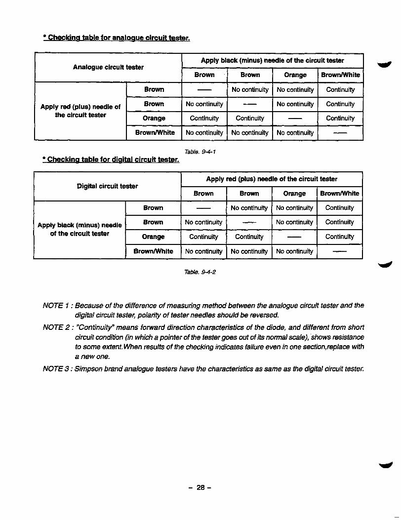
Checkina table for analoaue circuit tester.
Apply black (minus) needle of the circuit tester Analogue circuit tester e
Brown - Brown Orange Browmi te
Apply red (plus) needle of No continuity Brown - Continuity No continuity
the circuit tester Orange Continuity - Continuity Continuity I I I I
No continuity - No continuity No continuity
Table. 94- 1 Checkina table for diaital circuit tester.
Apply red (plus) needle of the circuit tester Digital circuit tester
Brown Brown I Brown
~~ - Continurty No continuity No continuity
Apply black (minus) needle of the circuit tester
Brown
Continuity - Continuity Continuity Orange
Continuity No continuity - No continuity
I I I I
BrownMlhite No continuity No continuity - No continuity
Table. 9-4-2
NOTE I : Because of the difference of measuring method between the analogue circuit tester and the digital circuit tester, polarity of tester needles should be reversed.
NOTE 2 : "Continuity" means forward direction characteristics of the diode, and different from short circuit condition (in which a pointer of the tester goes out of its normal scale), shows resjstance to some extent. When results of the checking indicates failure even in one section,replace with a new one.
NOTE 3 : Simpson brand analogue testers have the characteristics as same as the digital circuit tester.
- 28-

10. DISASSEMBLY AND ASSEMBLY
10-1 PREPARATION and PRECAUTIONS
1) Be sure to memorize the location of individual parts when disassembling the generator so that the generator can be reassembled correctly. Tag the disassembled part with the necessary information to facilitate easier and smoother reassembly.
2) For more convenience,divide the parts into several groups and store them in boxes.
3) To prevent bolts and nuts from being misplaced or installed incorrectly, replace them temporarily to their original position.
4) Handle disassembled parts with care; clean them before reassembly using a neutral cleaning fluid.
5) Use all disassembly/assembly tools properly, and use the proper tool for each specific job.
10-2 SPECIAL TOOLS for DISASSEMBLY and ASSEMBLY
ROTOR PULLER REAR COVER PULLER JIG
- 29-

10-3 DISASSEMBLY PROCEDURES 7 Step
1 - Part to remove
Fuel Tank ~~
Description Necessary tool Remarks
(1) Discharge fuel from the tank. 1. Turn the fuel cock to close (S). 2. Disconnect the rubber pipe from the
discharge the fuel. Wipe off spilt fuel. 3. Turn the fuel cock to OPEN (0) to
injection pump. (See Fig. 10-1.) 17 mm spanner Do not lose the gasket.
(2) Disconnect the fuel pipe and return pipe from the tank bottom. (See Fig. 10-2.) 1. Remove the hose clamp and pull the
12 spanner Do not lose the gasket 2. Remove the banjo bolt that fastens
Pliers
(3) Remove the fuel tank. 12 mm spanner or After removing the nut and washer, re- i box spanner move the fuel tank. (See Fig. 10-3.)
89 Flange Nut 4 pcs. 89Washer. . . . . . . . . 4 pcs.
fuel pipe off from the tank.
the return pipe.
: . . . . . . I (4) Remove the fuel fiter. Pliers
1. Remove the hose clamp, and pull out the air return pipe. (See Fig. 10-4.)
2. Remove the fuel filter bolts and the box spanner fuel fiter. 12 mm spanner or
Fig. 10- 1 F& 10-2
-I Fig. 10-3 Fig. 10-4
- 30-

Part to remove
Battery (Only electric starter type)
(1) Remove battery cable from battery. Remove the negative side cable first, and then the positive side.
, I I
- - Be careful not to short.
(2) Remove battery from battery base.
battery bolts, and battery. battery, and take off the battery holder,
box spanner Remove the two nuts that fasten the i 10 mm spanner or
69nut ........... 2pcs. i (3) Remove battery base from the pipe
frame. 6 9 b o l t . . . . . . . . . . . 2pcs.
WNUT . . . . . . . 2pcs. - @SPRING WASHER
. . . . . . . . . .2pcs. I
10 mm spanner or box spanner
BAlTERY SPACER . . . . . . . . . . 2 p a .
BATTERY ANGLE
BAlTERYCABLE
BATTERY
BATTERY BOLT 4 1 dl i- PIPE FRAME
I
v
Fig. 10-5
Part to remove Description
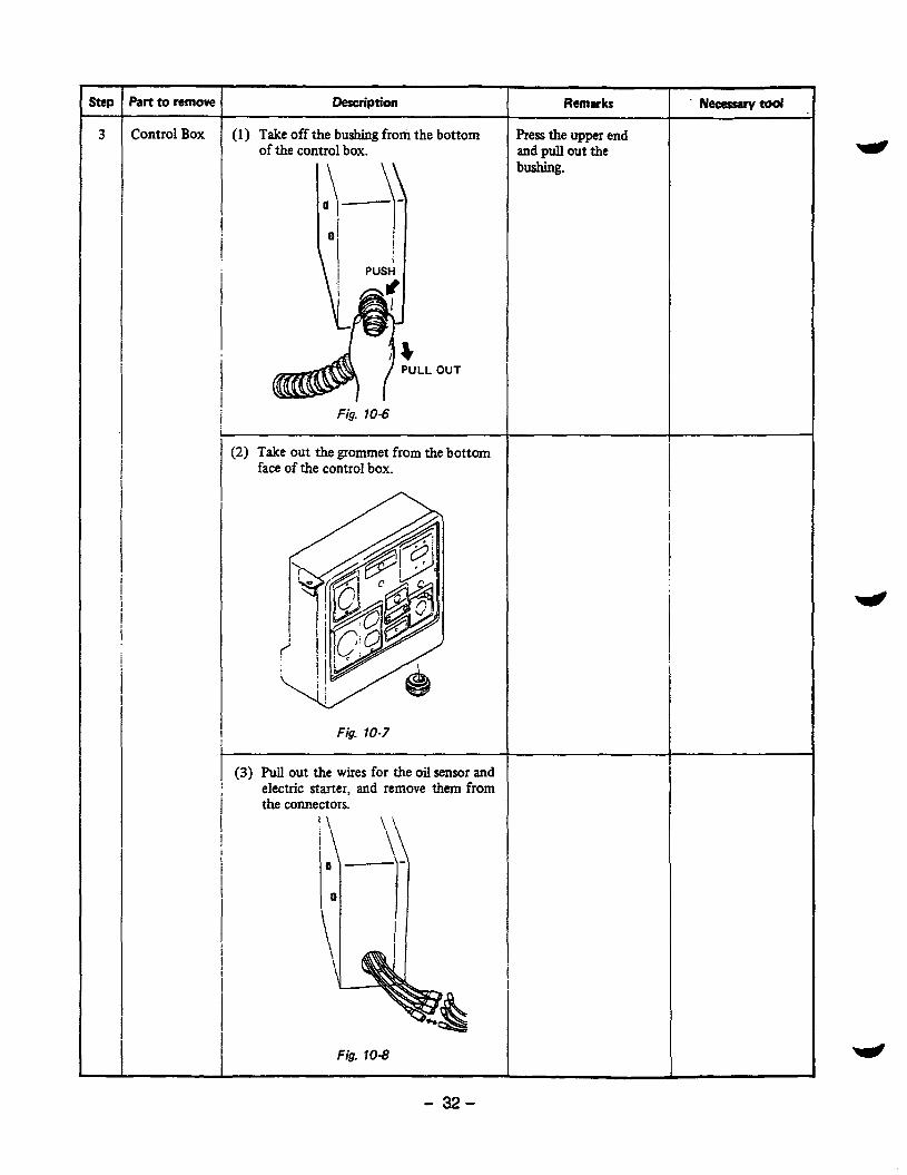
Control Box (1) Take off the bushing from the bottom I of the control box.
OUT
Fig. 10-6
1 (2) Take out the grommet from the bottom
I face of the control box.
\ I
c/
Fig. 10-7
t I (3) Pull out t h e wires for the oil Sensor and electric starter, and remove them from
i the connectors.
Fig. 10-8
- 32-
Remarks ~~
Press the upper end and pull out the bushing.

Pan to remove
Control Box
Pipe Frame
t Description Remarks
(4) Remove the control box from the frame. 64Washer.. ....... 3pcs. 6 4 b o l t . . ......... 3pcs.
Fig. 10-9
(1) Remove side plate A. 69 bolt . . . . . . . . . . . 2 pcs.
Remove the mount rubbers from side plate.
(2) Remove the nuts and bolts that fasten the generatar and frame together. 1. Remove the two bolts which fur the
alternator to the generator base. 2. Remove the four bolts and flange
nuts which fuc the engine to the engine base. 8@ bolt ........... 4 pcs. 84 flange nut . . . . . . . 4 p a .
Nuts are welded to the generator base.
Nexesarytwl
10 mm spanner or box spanner
12 mm spanner or box spanner
80 FLANGE NUT.. 4 pa.
RUBBER V.I. . . .
ENGINE BASE SIDE PLATE A
. . . . . - 2 pa.
2 pa.
4 DQ.
80 BOLT . . . . . - 4 pes. Fig. 70-70
- 33-
Part to remove 1 I
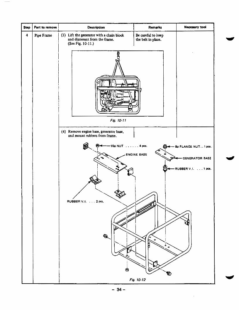
Pipe Frame t (3) Lift the generator with a chain block Be caref'd to keep
Description Necesrarytod Remarks
1 and dismount from the frame.
i the belt in place.
(See Fig. 10-1 1.)
! r
L Fig. 10-1 7
(4) Remove engine base, generator base, and mount rubbers from frame.
-100 NUT . . . . . . 4 pa. I
BASE
RUBBER V.I. . . . 2 pa.
%
Fig. 10-12
& FLANGE N U T . .
GENERATOR
e- RUBBER V.I. . . .
1 Pce.
BASE
1 Pce.
- 34-

Part to remove
Recoil Starter
- 6 Rear Cover
Description Remarks
(1) Remove recoil starter from rear cover. 69 bolt . . . . . . . . . . . 4 pes.
1
Fig. 10-13
1 (1) Take off the through bolt and remove Be careful not to lose
the starting pulley and spacer from rotor the key at removing shaft. Apply a box wrench on the head starting pulley. of through bolt and hit the wrench handle with a hammer counterclockwise
I ! toloosen
I f
Fig. 10-14
Necessary tool
10 mm spanner or box spanner
Box spanner or socket wrench Hammer
Fig. 10-15
- 35-

7 Step Part to remove Description
(2) Take off the rear cover. 1. Remove the four bolts which fasten
the rear cover to the adapter of the engine. 64bo l t . . . . . . . . . . . 4pcs.
2. Use a special tool “REAR COVER PCLLER” to remove the rear cover. a) insert the two bolts of the
special tool into the thread hole of the rear cover.
special too1 to the center hole of the rotor shaft.
c) Tighten the center bolt to pull out the rear cover.
b) Apply the center bolt of the
BOLT . . . . . . 4pcs.
Remarks Necessary tool
10 mm spanner or box spanner
Insert the two bolts sufficently and evenly or the thread hole may be damaged at remov- ing.
special tool 17 mm spanner Driver
’ BOLT
60 BOLT . . . . . 2 pa.
Fig. 10-16 Fig. 10- I7
I In c a ~ e that ‘REAR COVER PULLER” is un- available, remove the rear cover by the follow- ing instructions.
I . Insert the through bolt into the rotor
with a plastic hammer. boss or legs. Hit on the boss and legs of rear cover hit on the rear cover shaft and tighten lightly. Do not give a strong
I I
1 Fig. 10-18
Box spanner or socket wrench Plastic hammer
Description I Remarks Neasssrytoal
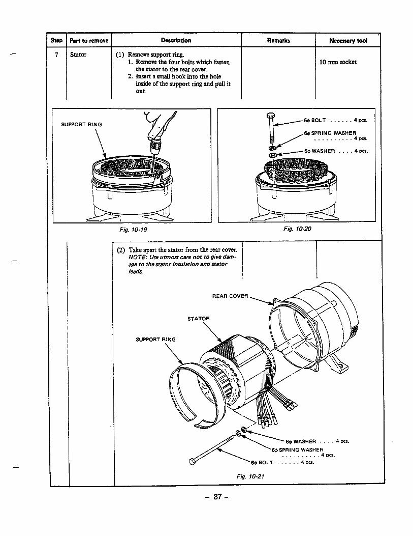
7 Stator (1) Remove support ring. 1. Remove the four bolts which fasten
2. Insert a small hook into the hole the stator to the rear cover.
inside of the support ring and pull it out. I
10 mm socket
@BOLT . . . . . . 4pa.
. . . . . . . . . &SPRING WASHER
..%pes.
60 WASHER . . . . 4 pa.
Fig. 10-20
I I (2) Take apart the stator from the rear cover. ’
NOTE: Use utmost care not to give dam- I age to the stator insulation and stator I leads I
SUPPORT
. . . . . . . . . ‘@SPRING WASHER
. 4 pes.
60 BOLT . . . . . . 4 pcs.
Fig. 10-2 7
- 37-
part to remove I Description I Remarks
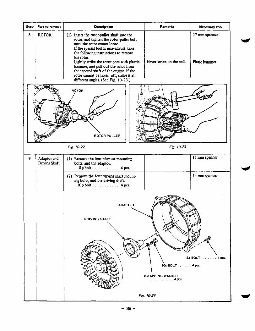
ROTOR (1) Insert the rotor-puller shaft into the rotor, and tighten the rotor-puller bolt until the rotor comes loose. If the special tool is unavailable, take the following instructions to remove the rotor. Lightly strike the rotor core with plastic hammer, and pull out the rotor from the tapered shaft of the engine. If the rotor cannot be taken off, strike it at different angles. (See Fig. 10-23.)
9 I Adaptor and Driving Shaft
I
Fig. 10-22 ~~ ~
Never strike on the coil.
Necetrarytool
17 mm spanner
mtic hamma
Fig. 10-23
(1) Remove the four adaptor mounting 12 mm spanner bolts, and the adaptor.
89bol t . . . . . . . . . . . 4pcs.
(2) Remove the four driving shaft mount- 14 mm spanner ing bolts, and the driving shaft.
109 bolt . . . . . . . . . . . 4 pa.
100 BOLT. . . . . . 4 pa.
100 SPRING WASHER . . . . . . . . . -4pCs.
Fig. 70-24 ~
- 38-

104 ASSEMBLY PROCEDURES
10-4-1 FRONT PROTECTOR amd FRONT COVER
(1) Aligh the driving shaft with the faucet joint of the flywheel and install it. lO@x30mrnbolt ... 4pcs. 10 # spring washer. . . 4 pcs.
L
9 - 68.6 N-m 550 - 700 kg-cm 39.8 - 50.6 ft-lb
(2) Install the adapter in the blower housing, making sure that its flat side is down and its fuel filter mounting boss on the air cleaner side. 8 # x25mmbolt ... 4pcs. 8 # spring washer. . . 4 pcs.
filter nting
200 - 230 kg- 14.4 - 16.6 ft-lb
boss
10-4-2 ROTOR
(1) Clean the tapered portion of driving shaft and the matching tapered hole of rotor shaft of oil and dirt using a waste cloth.
(2) Attach the rotor to the engine shaft. Tighten the through bolt tentatively. (See Fig.
Apply a wrench on the head of through bolt and hit it clockwise with a hammer to tighten.
10-26.)
Fig. 10-25
r
- 39-

10-4-3 STATOR and REAR COVER
(1) Set the stator on the jig so that grooves on the stator side match with the grooves of the jig. At the same time, be sure to set the stator on the jig so that the lead wires direct to the win- dow of rear cover.
Attach the support ring around the stator.
Check that the hooking holes are placed at the flat sides of the stator. (See Fig. 10-27.)
Direction of stator leads
Grooves of stator
(2) Insert four guide bolts in the rear cover and let them match with the grooves in the stator and set the rear cover over the stator.
(3) Take the stator leads out from the window of the rear cover.
(4) Tap lightly and evenly the upper surface of the board on the rear cover with plastic hammer to press fit the rear cover over the stator. (See Fig. 10-28.)
(5) Fix the stator to the rear cover with four bolts, washers and spring washers.(See Fig. 10-29.) 6 @ bolt. . - 4 pcs. 6 @ washer . . - 4 pcs. 6 @ spring washer. . . 4 pcs.
I lightening torque 1 I 4.9 - 5.9 N-m ~ 50 - 60 kgcm
3.6 - 4.3 fi-lb
Grooves I N of jig 1 ’ -U\ Jig
Fig. 10-27
”
Board \
Fig. 10-28
69 Bolt. . . . . . . . . 4 p a .
69 Spring washer. . . 4 pcs.
Fig. 10-29
- 40-

The dimensions of the stator bolts are shown in Table 10-1.
Tale. 10- 1
10-4-4 REAR COVER
(1) Attach the bush over the lead wires drawn out from the rear cover. Press the bush and into the window of the rear cover. (See Fig. 10-30.)
Fig. 1030
(2) Put the rear cover with stator over the rotor. . Tap on the rear cover evenly with a plastic
hammer to press the rotor bearing into the rear cover. (See Fig. 10-31 .)
Fig. 1031
- 41 -

(3) Fix the rear cover to the adapter with four bolts, spring washer, and washer. 6 @ x 2 5 m m b o l t . . . 4pcs. 6 @ washer. . . 4 pcs. 6 @ spring washer. . . 4 pcs.
I Tightening torque I ~
4.5 - 5.9 N-m 50 - 60 k- 3.6 - 4.3 ft-lb
10-4-5 RECOIL STARTER
(1) Remove the through bolt which has been ten- tatively attached to the rotor.
(2) Insert the key into the keyway of the rotor shaft.(See Fig. 10-33.)
Then, insert the spacer. Tapping the starter pulley with a plastic ham- mer, attach the starter pulley to the rotor shaft.
Fig. 70-33
(3) Apply a washer and a spring washer to the through bolt and insert it into the rotor shaft. Through bolt . - . 1 pce. 10 @ washer . . .1 pce. 10 @ spring washer. . . 1 pce. "The dimension of the through bolt is shown in Table 10-2.
L
t-
m 1
I Model l Z I S l d l I I
Table. 10-2
- 42-
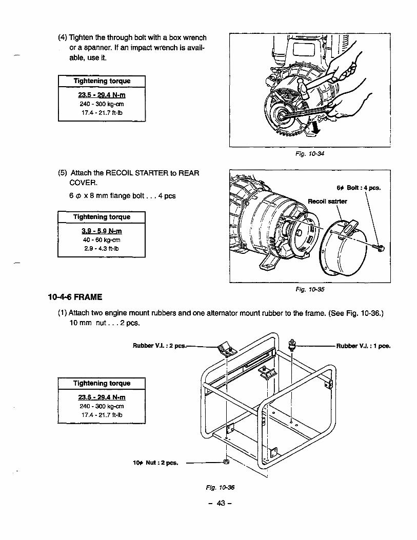
(4) Tighten the through bolt with a box wrench or a spanner. If an impact wrench is avail- able, use it.
240 - 300 kgcm 17.4 - 21.7 ft-lb
(5) Attach the RECOIL STARTER to REAR COVER.
6 @ x 8 mm flange bolt. . . 4 pcs
I Tightening torque I 3.9 - 5.9 N-m 40 - 60 kg-cm 2.9 - 4.3 ft-lb
Fig. 70-35
(1) Attach two engine mount rubbers and one alternator mount rubber to the frame. (See Fig. 10-36.) 10 mm nut.. .2 pcs.
V.I. : 1 pce.
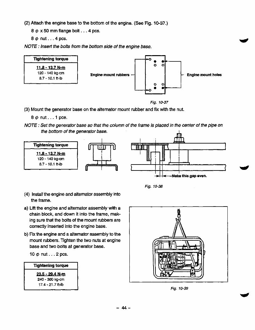
(2) Attach the engine base to the bottom of the engine. (See Fig. 10-37.)
8 @ x 50 mm flange bolt . . . 4 pcs. 8 @ nut . . . 4 pcs.
NOTE : Insert the bolts from h e bottom side of the engine base.
120 - 140 kgcm 8.7 - 10.1 ft-lb
Engine mount rubbers - Engine mount holes
Fig. 10-37
(3) Mount the generator base on the alternator mount rubber and fix with the nut.
8 @ nut. . . 1 pce.
NOTE : Set the generator base so that the column of the frame is placed in the center of the pipe on the bottom of the generator base.
11.8 - 13.7 N-m 120 - 140 kg-m 8.7 - 10.1 ft-lb
(4) Install the engine and alternator assembly into
a) Lift the engine and alternator assembly with a chain block, and down it into the frame, mak- ing sure that the bolts of the mount rubbers are correctly inserted into the engine base.
b) Fix the engine and a alternator assembly to the mount rubbers. lighten the two nuts at engine base and two bolts at generator base.
10 @ nut.. -2 pcs.
the frame.
Tightening torque I 235 - 29.4 N-m 240 - 300 kgcm 17.4 - 21.7 ft-lb
L
I I
Make this gap even.
Fig. 10-38
Fig. 70-39
- 44-

8 @ ~ 2 5 m m b o l t ... 2pcs.
I lightening torque
11.8 - 13.7 N-m 120 - 140 kgcm 8.7 - 10.1 ft-lb
NOTE : When tightening the nuts and bolts, slightly lift the engine and alternator assembly so that the weight is not applied to the mount rubbers
(5) Attach the stoppers to the frame.
NOTE 1 : Set the stoppers so that the engine base is placed in the center of the upper and the lower rubbers. (See Fig. 10-40.)
NOTE2 : If the engine mount rubbers are replaced with new ones, set the stoppers so that the upper rubber touches the engine base. The new mount rubber shall be dis- torted by approx. 3mm in one month.
8 @ x 12 mm bolt . . . 4 pcs.
I lightening toque I
Make this gap even.
Engine base
I I I
1 Fig. 70-40
. ~~ ~~ ~~
11.8 - 13.7 N-m 120 - 140 kgcm 8.7 - 10.1 ft-lb
- 45-
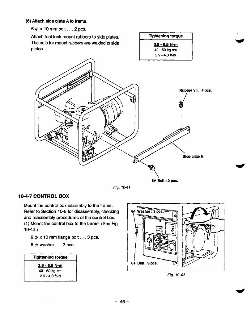
(6) Attach side plate A to frame.
6 @ x 10 mm bolt.. .2 pcs.
Attach fuel tank mount rubbers to side plates. The nuts for mount rubbers are welded to side plates.
I lightening toque I 3.9 - 5.9 N-m 40 - 60 kgcm 2.9 - 4.3 ft-lb
1 I
10-4-7 CONTROL BOX
Mount the control box assembly to the frame. Refer to Section 10-5 for disassembly, checking and reassembly procedures of the control box. (1) Mount the control box to the frame. (See Fig. 10-42.)
6 @ x 10 mm flange bolt. . -3 pcs.
6 @ washer. . .3 pcs.
40 - 60 kg- 2.9 - 4.3 ft-lb
69 Bolt : 2 pcs. Fig. 10-41
1 I Fig. 10-42
- 46-

(2) Connect the wires drawn out from the stator to the wires from the control box. Connect the oil sensor wires at the same time.
_-
NOTE : Connect the wires of the same color.
(3) Press the upper end of the bushing into the bottom window of the control box. (See Fig. 1 0-43 .) Attach the grommet for the oil sensor wires to the rear panel of the control box.
_-
t
I Fig. 10-43
(4) Fasten the one earth cable with 8 C#I terminal drawn out from the control box to the rear cover leg.
8C#Ix25mmbolt . . . lpce .
Fasten the other earth cable with 6i"terminal to the unpainted bolt hole on the frame.
(See Fig.1044.)
11.8 - 13.7 N-m 120 - 140 k g m 8.7 - 10.1 ft-lb
Control box 1 6# Terminal 8# Terminal m
Fig. 10-44
- 47-
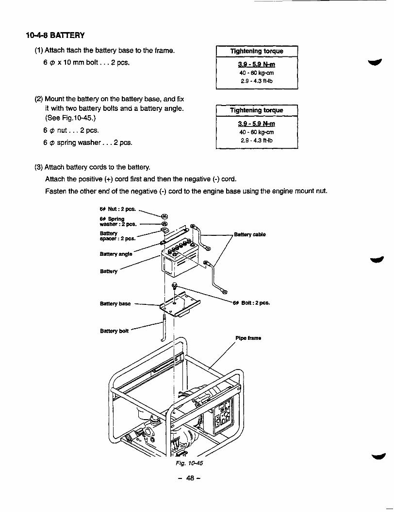
10-4-8 BAlTERY
(1) Attach ttach the battery base to the frame.
6cpxlOmmbolt . . . 2pcs.
(2) Mount the battery on the battery base, and fix it with two battery bolts and a battery angle. (See Fig. 1 0-45 .)
6 Q n ut... 2pcs.
6 @ spring washer. . .2 pcs.
3.9 - 5.9 N-m 40 - 60 kg-cm 2.9 - 4.3 ft-lb
I Tightening torque I 3.9 - 5.9 N-m 40 - 60 kgcm 2.9 - 4.3 ft-lb
(3) Attach battery cords to the battery.
Attach the positive (+) cord first and then the negative (-) cord.
Fasten the other end of the negative (-) cord to the engine base using the engine mount nut.
Battery cable
frame
Fig. 10-45
- 48-
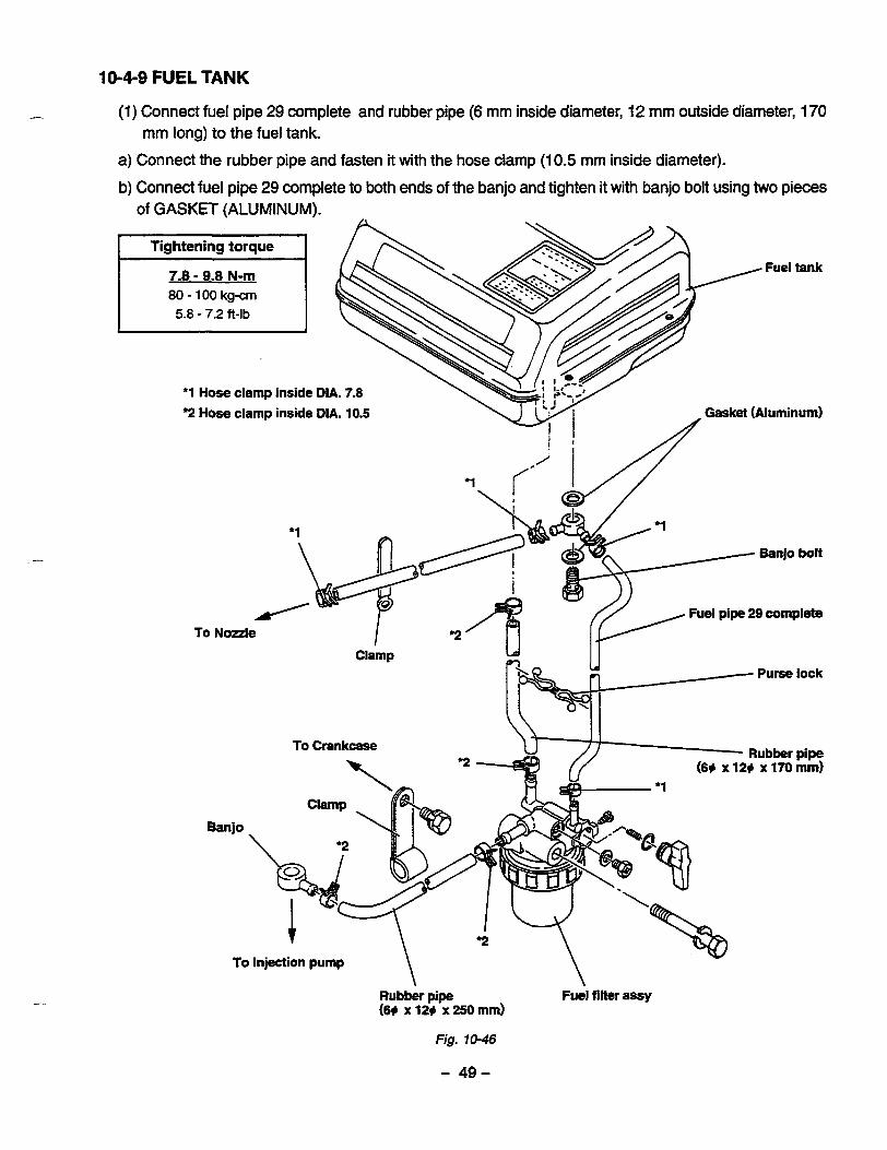
10-4-9 FUEL TANK
(1) Connect fuel pipe 29 complete and rubber pipe (6 mm inside diameter, 12 mm outside diameter, 170
a) Connect the rubber pipe and fasten it with the hose clamp (1 0.5 rnm inside diameter).
b) Connect fuel pipe 29 complete to both ends of the banjo and tighten it with banjo bolt using two pieces
mm long) to the fuel tank.
of GASKET (ALUMINUM).
Fuel tank
80 - 100 kg-cm 5.8 - 7.2 ft-lb
*1 Hose clamp inside DIA. 7.8 2 Hose clamp inside DIA. 10.5 Gasket (Aluminum)
Fuel pipe 29 complete To Nozzle
Rubber pipe (69 x 129 x 170 mm)
Clamp .
\ 2 I -\
To Injection pump \ \ Rubber pipe Fuel filter assy (6# x 12# x 250 mm)
Fig. 10-46
- 49-

(2) Mount the fuel tank on the mount rubbers attached to the side plates.
8 @ nut. . . 4 pcs.
8 rp spring washer. . . 4 pcs. Tightening torque
11.8 - 13.7 N-m 120 - 140 kg-cm 8.7 - 10.1 ft-lb
(3) Connect the fuel pipe.
a) Install the fuel filter assembly on the boss on the side of the adaptor (generator).
8 @ x 65 mm bolt. . . 1 pce.
b) Connect the other end of the pipe installed in Step (1 ) to the fuel filter.
Slide the hose clamp over the pipe, connect the pipe to the fuel filter, and clamp the pipe at the cor
rect point.Then, secure the pipe with the purse lock.
NOTE : Connect the shorter pipe of fuel pipe 29 complete to the fud filter. The hose clamp for the rubber pipe has an inside diameter of la5 mm, and that for fue/pipe 29 compiete is 7.8 mm in inside diameter.
c) Connect the longer pipe of fuel pipe 29 complete to the engine nozzle. The nozzle must be pulled up from the cylinder head before connecting the pipe to it. After pulling the nozzle up, slide the hose clamp (7.8 mm in inside diameter) over the pipe, connect the pipe to the nozzle, and fasten the pipe with the hose clamp at the correct point. Then, install the nozzle 9 on the head. Mount the bracket on the blower housing, and secure the pipe with the clamp.
Fit the banjo to the rubber pipe (6 mm in inside diameter, 12 mm in outside diameter, 250 mm long) and clamp it. Connect the other end of the pipe to the fuel filter and clamp it. Connect the banjo to the injection pump. A gasket must be placed on each side of the banjo. Use hose clamps 10.5 mm in inside diameter. Finally, clamp the pipe to the crankcase.
d) Connect the fuel filter and injection pump with pipe.
10-5 CHECKING, DISASSEMBLY and REASSEMBLY of the CONTROL BOX
10-5-1 CHECKING OF THE CONTROL BOX
Dismount the control box from frame. Remove the control panel and check each components and wiring. Refer to Section 9 for the detail of checking the components in the control box.
- 50-
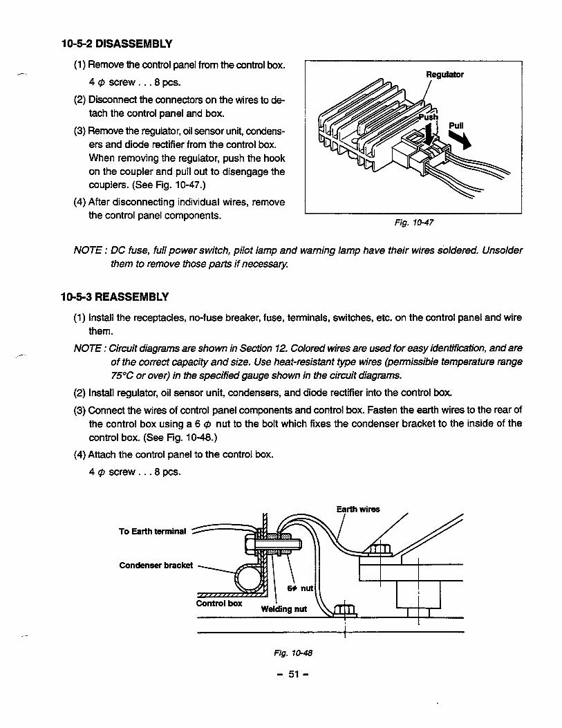
10-5-2 DISASSEMBLY
(1) Remove the control panel from the control box.
4 @ screw . . .8 pcs.
tach the control panel and box. (2) Disconnect the connectors on the wires to de-
(3) Remove the regulator, oil sensor unit, condens- ers and diode rectifier from the control box. When removing the regulator, push the hook on the coupler and pull out to disengage the couplers. (See Fig. 10-47.)
(4) After disconnecting individual wires, remove the control panel components.
Regulator
1
Fig. 10-47
NOTE : DC fuse, full power switch, pilot lamp and warning lamp have their wires soldered. Unsolder them to remove those parts if necessity
10-5-3 REASSEMBLY
(1) Install the receptacles, no-fuse breaker, fuse, terminals, switches, etc. on the control panel and wire them.
NOTE : Circuit diagrams are shown in Section 12. Colored wires are used for easy identification, and are of the correct capacity and size. Use heat-resistant type wires (permissible temperature range 75°C or over) in the specified gauge shown in the circuit diagrams.
(2) Install regulator, oil sensor unit, condensers, and diode rectifier into the control box.
(3) Connect the wires of control panel components and control box. Fasten the earth wires to the rear of the control box using a 6 @ nut to the bolt which fixes the condenser bracket to the inside of the control box. (See Fig. 10-48.)
(4) Attach the control panel to the control box.
4 @ screw. . .8 pcs.
To Earth terminal
E Condenser bracket &=
I I
Fig. 10-48
- 51 -
11 .TROUBLESHOOTING
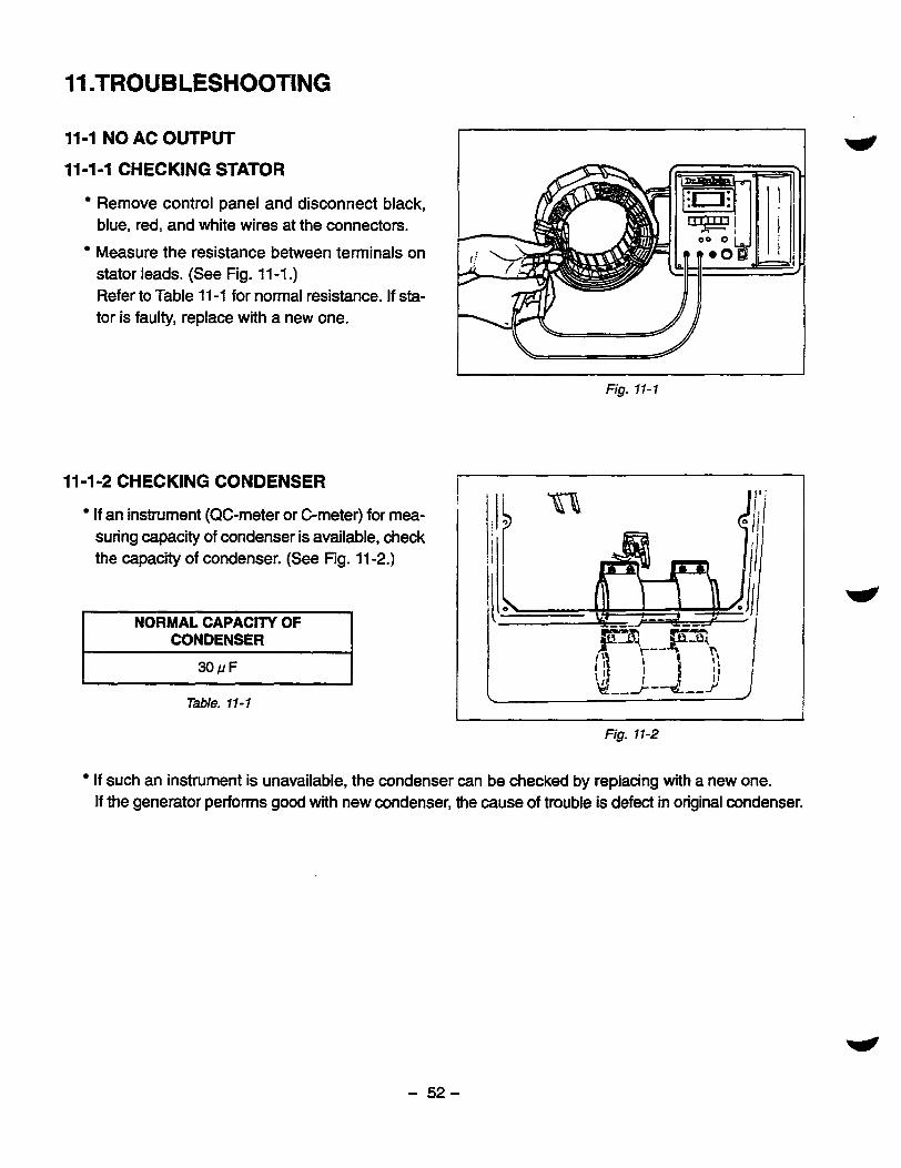
11-1 NO AC OUTPUT I- l l -1-1 CHECKING STATOR
Remove control panel and disconnect black, blue, red, and white wires at the connectors.
Measure the resistance between terminals on stator leads. (See Fig. 11-1 .) Refer to Table 11 -1 for normal resistance. If sta- tor is faulty, replace with a new one.
11-1-2 CHECKING CONDENSER
If an instrument (QC-meter or C-meter) for mea- suring capacity of condenser is available, check the capacity of condenser. (See Fig. 11 -2.)
NORMAL CAPACITY OF CONDENSER
Table. 11 - 1
Fig. 11-1
Fig. 11-2
If such an instrument is unavailable, the condenser can be checked by replacing with a new one. If the generator performs good with new condenser, the cause of trouble is defect in original condenser.
- 52-

11-1-3 CHECKING OF ROTOR
(1) CHECKING FIELD COIL
Remove rem cover and startor.
Unsolder the coil from the terminal on the rotor. (See Fig. 11 -3.)
Measure the resistance of field coil with a circuit tester. (See Fig. 11 -4.)
[ Remedy ]
I MODEL I RGD5000 I I RESISTANCE I 1.6 Q I
Table. 11-2
Fig. 11-3
If the resistance is not normal, replace rotor with a new one.
Fig. 1 1 4 - (2) CHECKING OF DIODES AND RESISTOR ON THE ROTOR
Unsolder and take out the diodes and a resistor from rotor.
Measure the resistance of diodes.
Polarity of
I [Continuity existsJ I I Fig. 11-5
Each rotor has three diodes. Check the resistance of each diode.
- 53-
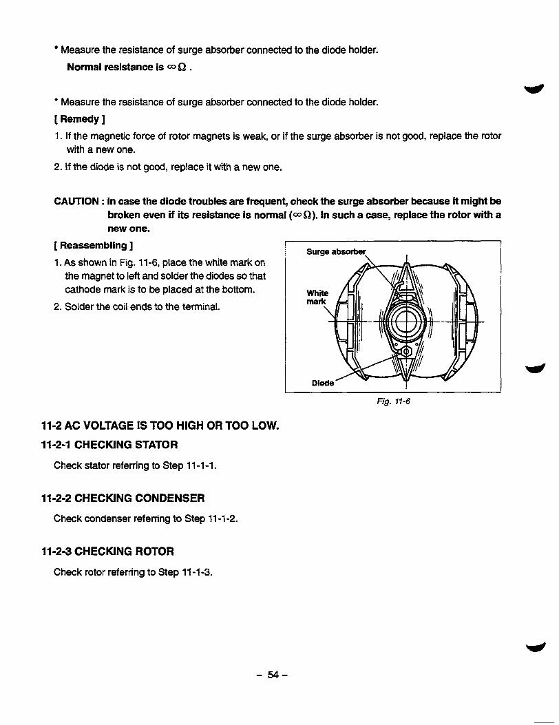
Measure the resistance of surge absorber connected to the diode holder. Normal resistance is 0 SZ .
* Measure the resistance of surge absorber connected to the diode holder. [ Remedy J 1. If the magnetic force of rotor magnets is weak, or if the surge absorber is not good, replace the rotor
with a new one. 2. If the diode is not good, replace it with a new one.
CAUTION : In case the diode troubles are frequent, check the surge absorber because it might be broken even if its resistance is normal (aSZ). In such a case, replace the rotor with a new one.
[ Reassembling ] 1. As shown in Fig. 11 -6, place the white mark on
the magnet to left and solder the diodes so that cathode mark is to be placed at the bottom.
2. Solder the coil ends to the terminal.
Surge absorber \ I
Fig. 11-6
11-2 AC VOLTAGE IS TOO HIGH OR TOO LOW. 11-2-1 CHECKING STATOR
Check stator referring to Step 11 -1-1.
11-2-2 CHECKING CONDENSER
Check condenser referring to Step 11 -1 -2.
11-24 CHECKING ROTOR
Check rotor referring to Step 11 -1 -3.
- 54-

11-3 AC VOLTAGE IS NORMAL AT NO-LOAD, BUT THE LOAD CANNOT BE APPLIED.
11-3-1 CHECK THE ENGINE SPEED. 7
If the engine speed is low, adjust it to the rated r.p.m.
'Refer to Step 11 -2-1 for engine speed adjustment.
11-3-2 CHECK THE TOTAL WATTAGE OF APPLIANCES CONNECTED TO THE GENERATOR.
Refer to Section 7 "RANGE OF APPLICATIONS for the wattage of the appliances.
If the generator is over-loaded, reduce the load to the rated output of the generator.
11-3-3 CHECK THE APPLIANCE FOR TROUBLE.
If the appliance is faulty, repair it.
11-3-4 CHECK IF THE ENGINE IS OVERHEATED.
If the cooling air inlet and/or cooling air outlet is clogged with dirt, grass, chaff or other debris, re- move it.
Fig. 11-7
11-3-5 CHECK THE INSULATION OF THE GENERATOR.
Stop the engine. Measure the insulation resistance between the live terminal of the receptacle and the ground terminal.
If the insulation resistance is less than 1 M Q, dis- assemble the generator and check the insulation resistance of the stator, rotor and the live parts in the control box. (Refer to Section 8-3.) Any part where the insulation resistance is less than 1 MQ, the insulation is faulty and may cause electric leakage.
Replace the faulty part. Fig. 11-8
- 55-
114 NO DC OUTPUT 1 1 4 1 CHECK THE AC OUTPUT.
Check the generator by following Step 11 -1 -1 through Step 11 -1 -3.
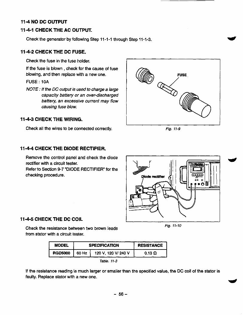
1 1 4 2 CHECK THE DC FUSE.
Check the fuse in the fuse holder.
If the fuse is blown , check for the cause of fuse blowing, and then replace with a new one.
FUSE : 10A
NOTE : I f the DC output is used to charge a large capacity battery or an over-discharged battev, an excessive current may flow causing fuse blow.
1 1 4 3 CHECK THE WIRING.
Check all the wires to be connected correctly.
1 1 4 4 CHECK THE DIODE RECTIFIER.
Remove the control panel and check the diode rectifier with a circuit tester. Refer to Section 9-7 "DIODE RECTIFIER" for the checking procedure.
1 1 4 5 CHECK THE DC COIL
I
Check the resistance between two brown leads from stator with a circuit tester.
Fig. 11-70
MODEL RESISTANCE SPECIFICATION
RGD5000 0.13 Q 60 Hz 120 V, 120 V/ 240 V - Table. 11-3
If the resistance reading is much larger or smaller than the specified value, the DC coil of the stator is faulty. Replace stator with a new one. *
- 56-
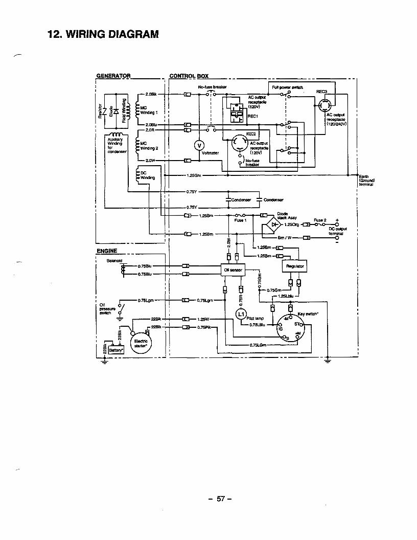
I-- GENERATOR CONlRO& BOX
T I--- ""_ " "1
c E I I
L
L
I I
I
1 f"- "
I I I
- 57-

“1