rh400 - holt cat machines & engines: caterpillar …€¦ · · 2010-08-17max. oil flow...
TRANSCRIPT
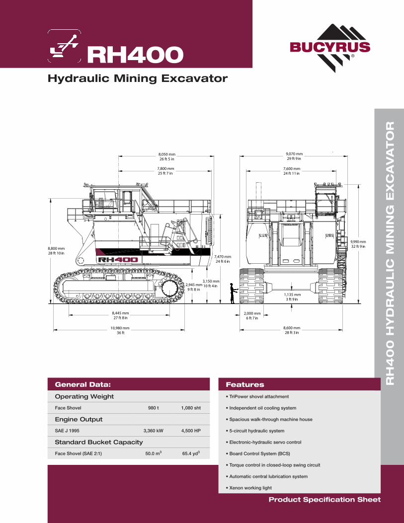
RH400Hydraulic Mining Excavator
RH
40
0 H
YD
RA
UL
IC M
ININ
G E
XC
AV
AT
OR
Product Specification Sheet
7,470 mm24 ft 6 in
7,800 mm25 ft 7 in
8,050 mm26 ft 5 in
3,150 mm10 ft 4 in
9,990 mm32 ft 9 in
2,945 mm9 ft 8 in
1,135 mm3 ft 9 in
8,445 mm27 ft 8 in
10,980 mm36 ft
8,800 mm28 ft 10 in
9,070 mm29 ft 9 in
7,600 mm24 ft 11 in
2,000 mm6 ft 7 in
8,600 mm28 ft 3 in
General Data:
Operating Weight
Face Shovel 980 t 1,080 sht
Engine Output
SAE J 1995 3,360 kW 4,500 HP
Standard Bucket Capacity
Face Shovel (SAE 2:1) 50.0 m3 65.4 yd3
Features
• TriPower shovel attachment
• Independent oil cooling system
• Spacious walk-through machine house
• 5-circuit hydraulic system
• Electronic-hydraulic servo control
• Board Control System (BCS)
• Torque control in closed-loop swing circuit
• Automatic central lubrication system
• Xenon working light

Operating WeightShovelStandard track pads 2,000 mm (6 ft 7 in)
Operating weight 980,000 kg (2,160,510 lb)
Ground Pressure 25.8 N/cm2 (37.4 psi)
Further track pads on request
Diesel EnginesMake and model 2 x QSK 60-C 2-stage
Total rated net power ISO 3046/1 3,360 kW (4,500 HP) 1,800 min-1
Total rated net power SAE J1349 3,360 kW (4,500 HP) 1,800 min-1
Total rated gross power SAE J1995 3,360 kW (4,500 HP) 1,800 min-1
No. of cylinders (each engine) 16
Bore 159 mm (6.25 in)
Stroke 190 mm (7.48 in)
Displacement 60.2 I (3,674 in3)
Aspiration 2-stage turbocharged;aftercooled and intercooled
Max. altitude without deration 4,880 m (16,000 ft) a.s.l.
Emission certification US EPA Tier 2
Fuel tank capacity 15,100 I (4,000 US gal)
• Hydraulically driven radiator fan with electronically controlled fan speed• Microprocessed engine control• Automatic rev. reduction• Heavy-duty air- filters with automatic dust evacuation• Two-stage fuel filter incl. water separator• Additional high-capacity water separator• Pre-lube starting system• Eliminator with centrifuge for engine oil filtration• Engine-oil-change interval of 1,000 hours
Electrical System (diesel drive)System voltage 24V
Batteries in series / parallel installation
6 x 244 Ah - 12 V each732 Ah - 24 V in total
Alternators 2 x 175 A each
Working spot lights 12 x high brightness Xenon lights
• Battery isolation relays• Emergency stop switches accessible from ground level, in engine
module and in operator’s cab
Hydraulic Oil CoolingOil flow of cooling pumps Diesel version Electric version
4 x 975 l/min (4 x 258 US gal/min)4 x 992 l/min (4 x 262 US gal/min)
Diameter of fans 4 x 1,524 mm (4 x 60 in)
• Cooling system is fully independent of all main circuits, i.e. controlled cooling capacity is available whenever engine is running
• Gear-type cooling pumps supplying high-volume, low-pressure oil to aluminum coolers
• Fan speed is thermostatically controlled• Extremely high cooling efficiency to ensure optimum oil temperature
Automatic Lubrication SystemCapacity of grease container 1,000 l (264 US gal)
• Dual-circuit system with hydraulically driven heavy-duty pump and electronic time relay control to adjust the pause / lube times
• Connected to the lubrication system are the swing roller bearing with internal gearing and all pivot points of attachment, bucket and cylinders
• System failures displayed by Board Control System• Grease filters (200 μm) between service station and container as well
as directly behind grease pump
Electrical Motors (optional)Type 2 x Squirrel cage induction motor
Output 3,200 kW
Voltage 6.6 kV +/- 10% (other on request)
Total rated current IN 332 A
Frequency 50 Hz (or 60 Hz optional)
Revolutions 1,500 min-1 (1,800 min-1 optional)
Max starting current 780 A
• Custom-made electric motors with increased gap between rotor and stator to withstand severe mining conditions
• Power limit control by Pump Management System
Hydraulic System with PMSMain pumps (Diesel and electric version) 8 x variable flow axial piston pumps
Max. oil flow Diesel versionElectric version
8 x 936 I/min (8 x 247 US gal/min)8 x 935 I/min (8 x 247 US gal/min)
Max. pressure, attachment 31 MPa = 310 bar (4,495 psi)
Max. pressure, travel 36 MPa = 360 bar (5,220 psi)
Swing pumps Diesel versionElectric version
6 x reversible swash plate pumps6 x reversible swash plate pumps
Max. oil flow Diesel versionElectric version
6 x 488 I/min (6 x 129 US gal/min)6 x 496 I/min (6 x 131 US gal/min)
Max. pressure, swing circuit 35 MPa = 350 bar (5,080 psi)
Total volume of hydraulic oil Approx. 13,000 I (3,450 US gal)
Hydraulic tank capacity Approx. 10,000 I (2,640 US gal)
• Pump Managing System (PMS) contains:• Electronic load limit control• Flow on demand from main pumps depending on joystick position• Automatic regulation of main pumps to zero flow without demand• Automatic rpm reduction of engine speed during working breaks• Reduced oil flow of main pumps at high hydraulic oil temperature
or at high engine temperature• Pressure cut-off for main pumps• Cooling of pump transmission gear oil• Filters:
• Full-flow high-pressure filters (100 μm) for the main pumps, in-stalled directly behind each pump
• High pressure filters (100 μm) for the closed swing circuit• Full-flow filters (10 μm) for the complete return circuit• Full-flow filters (10 μm) for the cooling return circuit• Pressure filters (40 μm and 6 μm) for servo circuit• Transmission oil filters (40 μm)
UndercarriageTravel speed (2 stages) 1st stage
2nd stageMax. 1.7 km/h (1.06 mph) Max. 2.2 km/h (1.37 mph)
Max. tractive force 4,140 kN (422 t = 930,380 lb)
Gradability Max 36%
Track pads (each side) 48
Bottom rollers (each side) 7
Support rollers (each side) 2 plus a skid plate in between
Travel drives (each side) 1 planetary transmission with2 two-stage axial piston motors
Parking brake Wet multiple disc brake,spring-applied / hydraulically released
• Cast double-grouser combined pad-links with bushings connected by hardened full floating pins
• All running surfaces of sprockets, idlers, rollers and pad links as well as teeth contact areas of sprocket and pad links are hardened
• Fully hydraulic self-adjusting track tensioning system with membrane accumulator
• Automatic hydraulic retarder valve to prevent over-speed on downhill travel• Acoustic travel alarm• Idlers, bottom rollers and support rollers are connected to the
automatic lubrication system
Operator’s CabOperator’s eye level approx. 8.8 m (28 ft 10 in)
Internal dimensions of cab LengthWidthHeight
2,200 mm (7 ft 3 in)1,600 mm (5 ft 3 in)2,150 mm (7 ft 1 in)
Internal dimensions of amenity cab
LengthWidthHeight
1,600 mm (5 ft 3 in)1,600 mm (5 ft 3 in)2,150 mm (7 ft 1 in)
• Pneumatically cushioned and multi-adjustable comfort seat with lumbar support, safety belt, head and arm rests
• Safety switch in seat cushion to neutralize automatically the hydraulic controls when operator leaves the seat
• Joystick controls integrated in independently adjustable seat consoles• Fold-away auxiliary seat with safety belt• FOPS (rock guard; approved acc. to DIN ISO 3449) integrated into cab structure• All-round safety glass, armored windshield and sliding side window• Windshield with parallel intermittent wiper / washer• Roller blind at windshield• Robust instrument panel incl. large colored BCS screen with transflective
technology• Board Control System (BCS) electronic monitoring and data logging system
for vital signs and service data of engines, hydraulic and lubrication system• Machine access via retractable boarding ladder, hydraulically operated
Attachments• Boom and stick are torsion-resistant, welded box design of high tensile
steel with massive steel castings at pivot areas• Welding procedures allow for internal counter-welding (double prep
weld) wherever possible• Boom and stick are stress-relieved after welding• Inspection hole in boom and stick• Catwalks with rails at boom• Pressure-free lowering of boom and stick by means of a float valve• Shovel attachment with patented TriPower kinematics ensuring the
following main features: • Horizontal automatic constant-angle bucket guidance • Vertical automatic constant-angle bucket guidance • Automatic roll-back limiter to prevent material spillage • Kinematic assistance to hydraulic forces • Constant boom momentum throughout the whole lift arc • Crowd force assistance
• All buckets are equipped with a universal wear package suitable for all standard applications, which consists of: • Special liner material covering main wear areas inside and outside of bucket• Lip shrouds between teeth • Wing shrouds on side walls • Heel shrouds at bottom edges • Special wear packages for highly abrasive materials on request
Swing SystemSwing Drives 6 compact planetary transmissions
with axial piston motors
Parking Brakes Wet multiple disc brake,spring-loaded / hydraulically released
Max. swing speed 4.0 rpm
Swing ring Triple race roller bearingwith sealed internal gearing
• Closed-loop swing circuit with torque control• Hydraulic braking of the swing motion by counteracting control• All race ways of swing ring as well as grease bath for internal gearing
supplied by automatic central lubrication system
Retractable Service StationRetractable service station installed underneath the engine module and easily accessible from ground.Equipped with:• Quick couplings for:
• Diesel fuel • Engine coolant - left / right • Pump transmission gear oil - left / right • Engine oil (oil pan) - left / right • Engine oil (additional tank - optional) - left / right • Hydraulic oil tank • Grease container
• CAT jump start socket• Indicator lights for fuel tanks left/right FULL and grease container FULL
Optional EquipmentGeneral• Export crating• Finishing as per end user’s corporate colors• Customizing of logos as per customer’s specification
Superstructure• Hydraulic service crane on superstructure with auxilliary engine• Mesabi radiators instead of standard radiators• 2nd retractable boarding ladder on right-hand side of engine module• Various cold-weather packages• Additional lighting
Cab• Various heating and air-conditioning systems• Outside-mounted sun shields• Additional instrumentation
Undercarriage• Track-pad width 1,800 mm
Further optional equipment on request
161718192021 15 14 13 12 11 10 9 8 7 6 5 4 3 2 1 0 m
556065 50 45 40 35 30 25 20 15 10 5 0 ft
m
15
16
17
18
19
20
21
14
13
12
11
10
9
8
7
6
5
4
3
2
1
0
1
2
3
ft
50
55
60
65
45
40
35
30
25
20
15
10
5
0
5
10
Effective Date: February 2010. Product specifications and prices are subject to change without notice or obligation. The photographs and/or drawings in this document are for illustrative purposes only. Refer to appropriate Operator’s Manual for instructions on the proper use of this equipment. Failure to follow the appropriate Operator’s Manual when using our equipment or to otherwise act irresponsibly may result in serious injury or death. The only warranty applicable to our equipment is the standard written warranty applicable to the particular product and sale and Bucyrus makes no other warranty, express or implied. Bucyrus is a registered trademark of Bucyrus International, Inc. in the USA and many other countries. Copyright 2010 Bucyrus International, Inc.
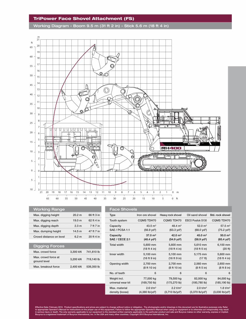
Working RangeMax. digging height 20.2 m 66 ft 3 in
Max. digging reach 19.0 m 62 ft 4 in
Max. digging depth 2.3 m 7 ft 7 in
Max. dumping height 14.5 m 47 ft 7 in
Crowd distance on level 6.2 m 20 ft 4 in
Digging ForcesMax. crowd force 3,300 kN 741,610 lb
Max. crowd force at ground level
3,200 kN 719,140 lb
Max. breakout force 2,400 kN 539,350 lb
TriPower Face Shovel Attachment (FS)
Working Diagram - Boom 9.5 m (31 ft 2 in) - Stick 5.6 m (18 ft 4 in)
Face ShovelsType Iron ore shovel Heavy rock shovel Oil sand shovel Std. rock shovel
Tooth system CQMS TDH70 CQMS TDH70 ESCO Posilok S130 CQMS TDH70
CapacitySAE / PCSA 1:1
43.5 m3
(56.9 yd3)48.4 m3
(63.3 yd3)52.0 m3
(68.0 yd3) 57.5 m3
(75.2 yd3)
CapacitySAE / CECE 2:1
37.0 m³(48.4 yd³)
42.0 m³(54.9 yd³)
45.0 m³(58.9 yd³)
50.0 m³(65.4 yd3)
Total width 5,600 mm (18 ft 4 in)
5,600 mm (18 ft 4 in)
5,610 mm (18 ft 5 in)
6,100 mm(20 ft)
Inner width 5,100 mm (16 ft 9 in)
5,100 mm (16 ft 9 in)
5,175 mm (17 ft)
5,600 mm (18 ft 4 in)
Opening width 2,700 mm (8 ft 10 in)
2,700 mm (8 ft 10 in)
2,560 mm (8 ft 5 in)
2,650 mm(8 ft 8 in)
No. of teeth 6 6 6 6
Weight incl. universal wear kit
77,000 kg(169,750 lb)
79,500 kg(175,270 lb)
82,000 kg(180,780 lb)
84,000 kg(185,190 lb)
Max. material density (loose)
2.6 t/m3
(4,380 lb/yd3)2.2 t/m3
(3,710 lb/yd3)2.0 t/m3
(3,370 lb/yd3)1.8 t/m3
(3,030 lb/yd3)