rheology (international) shannon ltd, · the viscometer is safe to use with such fluids however the...
TRANSCRIPT

Rheology (International) Shannon Ltd,
+353-61-471334+353-61-471042
Tel:Fax:E-Mail:
\It7
Industrial Estate,Shannon,Co. Clare,Ireland.

TABLE OF CONTENTS
11.0 Introduction.
42.0 Precautions.
3.0 Calibration.
7
94.0 Setting up yom Viscometer.
Choosing an appropriate Spindle and Speed. 1.1.5.0
136.0 Operating Instructions.
14
IS19
6.16.26.36.46.56.6
BASIC ENTRY
SPINDLE SELECrlON process
SPEED SELECrlON Routines
PRINT and RAMP Entry
RESE1TING AFTER AUTOZERO
SCREEN Options
21
24
25
267.0 Printer and Chart Recorder Information.
308.0 Viscometer Trouble Shooting.
Computer Upgrade for the RI Series 2. 319.0
3210.0 Repairs and Warranty.
33
34
35
Figure 1
Figure 2
Figure 3
Circuit Board Schematics
Front Panel Interface
Assembly Schematic
Appendix:Full Scale V~cosity Charts
M
J.:rl

The Rheology International ~eries 2 Viscometer- is designed specifically
to be of equal value in a Quality Control testing role or in a detailed
In a Q.C operation, users will find the fast startlaboratory analysis.
routine simple and effective, while laboratory users will appreciate the
capability to program speed ramps and print intervals for "walk away"
operations.
The first aspect of note in operating the Series 2 Viscometer is the use of
screen prompts and confirmations during start-up. We hope you will like
the way the instrument tries to communicate and interact with you, the
Our aim has been to ensure ease of use with the minimwnuser.
opportunity for error.
In operation, the Rheology International viscometer rotates a sensing
element in a fluid and measures the torque necessary to overcome the
This is accomplished by driving theviscous resistance to the movement.
immersed element, which is called a spindle, through a spirally wound
spring via the pivot point assembly. The percentage torque wind-up of the
spring due to the viscosity of the fluid is the primary data reference, and
referred to as engineering units or the "E" value. As the sensing element
is mechanically and electronically calibrated to give a known resistance at
"full scale deflection" (approx. 70 degrees deflection), and as the spindles
have known rheological properties, the % deflection allows derivation of
other necessary viscosity parameters.
To ensure that results are optimisecl the Instrument warns of operating
circumstances where the % deflection is less than 10% indicated by an
"L" in the display; (See Operating Instructions, Section 6), or greater than

90% indicated by an "H" in the Display; (See Operating Instructions,
Section 6).
Care should be taken to ensure that the Instrument is not operated above
the 100% Torque position. indicated by an "OUT OF RANGE" or the
display; (Operating Instructions, Section 6) as this could cause undue
If in doubt as to Speed andstress and damage within the instrument.
Spindle selection, please consult the Full Scale Viscosity Charts at the
back of this manual,
When using the standard range of ASTM spindles the recommended
container is a 600mllowfonn Griffin Beaker. Furthennore the guard-leg
supplied with the "M" instrument is necessary for rheological precision.
A guard-leg as not necessary with "HI" and "H2" Instruments.
Using the DIN system (confonning to DIN 53019 Part 1) requires an
Adaptor Part to be fitted to the Bayonet Adapter in the case of the M &
H models. This is a reasonably tight fit and will require care
changing. Once fitted the DIN spindle and cylinder components are
True DIN operation is available with thedesigned for fast interchange.
14mm, 24mm and 3Omm spindles and the appropriate cylinder.
higher viscosity ranges it is possible to run the system on a wide-gap
basis, i.e. not to DIN recommendations; these configurations are the
l4mm and 24mm spindle in large cylinder (appropriate to the 3Omm
spindle).
The Viscometer is able to measure over a number of ranges since the
Viscosity is proportional to the torque wind-up of the spring: the torque
wind-up is proportional to the spindle speed, and is related to the spindle
size and shape. For a material of given viscosity the drag will be greater
as the spindle size and/or rotational speed increases. The minimw

viscosity range is obtained by using the largest spindle at the highest
speed, and the maximum viscosity range by using the smallest spindle at
the slowest speed, (refer to Full Scale Viscosity Chart Guideline).
AUTOZERO is an inbuilt operation of the Instrument during start-up, or
This operation must be done with the spindle in air.new instructions.
During AUTOZERO the instrument is running the spindle at 20RPM,
and noting internal mechanical and electronic conditions whether created
The value whichinternally or as a result of the operating environment.
displays after Autozero, is an electronic value within the transducer (!!Q!
Millipascal seconds etc.) arising from this test, and is either added or
subtracted from all test values until the next AUTOZERO is performed.
This ensures complete instrument accuracy over long operating periods.
AUTOZERO should not be perfonned in any medium other than air (e.g.
partially in fluid will give meaningless results), and care should be taken
to ensure that the instrument is fully at rest during the procedure.
The Viscometer will start/commence a DOWN RAMP at any desired
speed up to 500 RPM; however if in manual operation and requiring a
speed reduction in excess of 50 RPM please return to ZERO and restart at
new speed.
Stated instrument accuracy of %.1 % of full scale is achieved with spindles
nmning to COlTect concentricity tolerances. The No.1 spindle is not
recommended above 50 RPM d1;le toturbul.ence effect.
~~
~;NOTE: When using ASTM spindles it is not advised to use speeds ~~
greater than lOORPM,as turbulence will occur in the~
sample.

2.0 PRECAUTIONS
USING FLAMMABLE OR EXPLOSIVE LIQUID
The Viscometer is safe to use with such fluids however the power supply
is not and should be kept at a safe distance. If in doubt please consult
your dealer and ask for a customised long-length connecting cable.
CARING FOR YOUR VISCOMETER
Do not drop or severely jar the Instrument. The spindle connector is(a)
quite ~usJ",- however, damage to spindles, pivot assembly or
transducer due to mishandling is not covered under warranty.
(b) Do not invert the instrument with a fluid coated spindle attached.
Avoid exposing the Viscometer to temperatures greater than 40(c)
degrees Centigrade.
(d) Avoid applying side or down thrust to the spindle connector. The
pivot point can be damaged by rough treatment.
(e) After attaching the spindle, and before commencing operations,
please check that the pivot is correctly seated by gently oscillating
the spindle manually.
CARE IN ATTACHING ASTM SPINDLES

(a) Always remember that the ASTM spindles have a left hand, or
Always lift the spindle coupling whenanticlockwise thread.
attaching or removing a spindle to protect the pivot bearing point.
Hold the shaft with one hand, and screw the spindle with the other,
( Refer to Figure 3).
Never ~! the spindle connector upwards.\0)
CARE IN ATTACHING DIN SPINDLES
(a) When changing from the ASTM to the DIN spindle system care
should be exercised when removing the ASTM adapter for insertion
The fixed DIN spindle is only used inof a fixed DIN spindle.
conjunction with the H2 model. A hook type connection is used
with L, M and HI models.
When fitting a DIN spindle use care when inserting the DIN spindle.(b)
Ensure the spindle shaft is in a straight alignment.
When fitting or changing DIN (or any) spindles similarly ensure(c)
that force or abrasion does not occur at the pivot point and bearing.
Lack of care on this issue will result in unnecessary friction at the
bearing affecting the instrument's accuracy, eccentric rotation due to
wear on the precise location point of the piVO4 or even the need for a
complete rebuild.

TO A vom INACCURATE READINGS
Ensure that the spindle is screwed on fully.(a)
Ensure that the face of the spindle nut and the machined surface on(b)
the lower part of the pivot shaft are smooth and clean to allow full
contact, and avoid causing eccentric rotation.
AUTO ZERO each time a different spindle is attached.(c)
Allow the spindle and guard leg (ASTM) or spindle and cylinder(d)
(VL Adaptor / DIN) to reach the same controlled temperature as the
fluid under test.
Allow the test material to reach the controlled temperature before(e)
commencing testing case, and avoid temperature gradients in the
material. If necessary, test the temperature at a variety of positions
in the sample to ensure regularity.

CALmRATION3.0
RI:2:M
The RI:2:M is calibrated to U.S. Bureau of Standards values on the basis
of the Instruments use, with the spindle guard-leg attached, in a 600ml
low form Griffin Beaker. If the instrument is used in a larger container
the ranges over which MI (ASTM Disc Spindle), and M2 spindles
measure will be slightly increased. This effect is negligible with spindles
M3 to M7.
The readings taken with the RI:2:M ASTM spindles in containers other
than the type specified above, and/or without guard legs can be used for
comparative purposes only.
A condition of turbulent flow is produced by an MI spindle when rotating
Below IOOmPa.s a slight degree of non-linearityat 60RPM and over.
between indicated and absolute viscosity will be noticed.
The M7 spindle has a narrow "neck" in its shaft rather than the groove
found on the other spindles. The spindle should be immersed in the fluid
so that half of this "neck" is covered.
,I RI:2:BI1H2
In all other respects theirBoth these are used without guard legs.
calibration is based on the same operating conditions as those appropriate
to the RI:2:M model above. It is not suggested that they be used for the
measurement of low viscosities.

CALIBRATION TEST PROCEDURE
Obtain a standard calibration fluid of a viscosity close to user's
normal operating conditions. Set up in a water bath with the
temperature of the fluid at 25°C., ensuring no internal temperature
gradients.
Fluids used for N.I.S.T. certified andcalibration are are
accompanied by relevant certificates to assure authenticity,
2. Ensure that the Instrument is assembled according to the instructions
in Section 4 on page 9.
3. It is important to note that the viscometer is properly balanced, by
noting the bubble level on the base block. This can be done by
adjusting the stand legs.
4. Power-up the instrument and when the display has settled note the
digital reading. Ensure that the values displayed after AUTOZERO
are less than 100 counts, ideally ZERO, (AUTOZERO must be done
in air). If this number is exceeded please refer to page 33 of this
manual for the SERIES 2 mainboard diagram. Open the front panel
of your instrument. Select Pot Number VR5 (AUTOZERO pot) and
span the pot so than readings as close to ZERO are attained.
s. After the AUTOZERO procedure, lower the correct spindle into the
calibration fluid and rotate the spindle at the prescribed speed. Note
the reading, adjust VR4, Calibration/Span pot as per page 33 until
the display reads as close as possible to the calibration fluid value.
Ensure the temperature reading is constant.

14.0 SETTING UP YOUR VISCOMETER
This section should be read in conjunction with Figure 3 on page 35 at the
back of the manual.
1. Remove the black base stand from its packing carton.
Take the lift mechanism out of the carton carefully.2I
Undo the bracket which holds the viscometer support rod and3.
hydraulic lift mechanism by unscrewing the nut on the bottom end
of the viscometer support rod.
Ali~ the viscometer support rod and the hydraulic lift bar with the4.
Compress the hydraulic lift barholes provided in the base stand.
such that the viscometer support rod fits completely through the
larger hole(15mm) in the base stand. Use the original fastening nut
to secure the support rod on the under side of the base stand.
Unpack the viscometer (use the straps provided) to lift thes.Remove theinstrument carefully from the packing carton.
viscometer from the clear plastic bag and remove protecive guard
from around the spindle shaft.
6. To mount the viscometer head onto the stand, align the viscometer
mounting plate and support pins as shown in Figure 3. Push-fit the
viscometer head onto the support pins until a good fit is found.
Ensure the viscometer is centred between the feet of the base stand.7.

8. Secure the viscometer head by tightening the locking grub screw
with the alIen key (3mm) provided. (The screw tightens in a clock-
wise direction).I
9. Attach the spindle guard leg to the underside of the viscometer head
by locking the nut on the spindle guard leg to the hole provided.
10. Level the viscometer using the bubble level located on the
viscometer head. The bubble should be at the centre of the black
circle on the level.
11 Remove the clear plastic film which is used to protect the LCD ()
display during transit.
12. Connect a correct plug to the end of the power cable.
. Ensure that the instrument is provided with a good earth connection.
13. Verify that the viscometer (and any ancillary equipment) matches
the power source ~ plugging in.
1.4. If using a chart recorder, refer to chart recorder infonnation section.
15. Insert the Temperature Probe plug into the plug socket on the
back of the Series 2 viscometer head where it is marked
TEMP.
Ensure that it is secured.

The maximum reading the viscometer can achieve or its full scale varies
with speed selection and spindle chosen. To assist in instances where new
substances are under test, alternative shear rate levels are required, or
other attachments or accessories are being used. An outline of the full
scales appropriate to a number of rotational speeds and spindle choices are
at the back of this manual.
With the spindles and speeds currently available, Rheology International
viscometers can measure viscosity ranges from 1 to 400,000,000 mPa.s.
If the approximate viscosity of the fluid under test is known the
appropriate speed/spindle combination can be located using the charts.
For example, a test fluid is thought to have a viscosity of 980mPa.s.
Choose a speed spindle combination which gives a full scale viscosity
range such that 980 is between 10% and 90% of this range.
For example, Spindle M2 and Speed 20 RPM has a Full Scale Viscosity of
2000mPa.s. The test fluid's viscosity of 980mPa.s is a very satisfactory
41% of this value.
However if 1000 mPa.s full-scale viscosity had been chosen, 980mPa.s
would equal 98% of full-scale. The corresponding speed (10 RPM) and
spindle (MI) will give a viscosity reading outside the best accuracy range
of the instrument. This will be indicated by an "H" in several of the data
displays; (See Operating Instructions, 6.0).

If 33,333mPa.s full-scale viscosity had been chosen, 980mPa.s would be
2.9%. of full-scale. Therefore the colTesponding speed and spindle will
This willgive a reading under the best accuracy range of the instrument.
be indicated by an "L" on several of the data displays: (See Operating
Instructions, 6.0).
To choose 833.3mPa.s would give 980mPa.s equal to 117.6% of full
scale. The viscosity of our fluid would then be outside the range of the
corresponding speed and spindle. This will be indicated by an "OUT OF
RANGE" on the display, (refer to Operating instructions section 6.0).
If the viscosity of the fluid as not known beforehand, trial and en-or can be
used but by beginning with the slower speeds, and spindles with lower
viscosity ranges.
As stated in the introduction, when using Engineering units and with a
display reading greater than 10 and less than 90 the viscometer is "IN
RANGE".

6.0 OPERATING INSTRUCTIONS
Section 1 Basic Entry
Section 2 SPINDLE SELECTION Routines
Section 3 SPEED SELECTION Routines
Section 4 PRINT and RAMP Entry
Section 5 RESETfING after AUTOZERO
Section 6 SCREEN Options

SECTION 6.1 BASIC ENTRY
1.1 PRINTER OUTPUT No (2) selected, Instrument proceeds to rampingselection
YES (1) NO (2)
1.2 RAMPING No (2) selected, Instrument proceeds to SpindleSelection Screen
YES(l) NO(2)
1.3 D(I) A(2) CP(3) T(4) Spindle selection process as described in section 2
SSA(5) HS(6) VL(7)

SECTION 6.2 SPINDLE SELECTION Process- -- - - - - ~ - - ~ - - - - - - --
2.1~~
D(l) A(2) CP(3) T(4) Spindle set selection screenwhere:-
D = DIN 53 O19Set" 'A = ASTM Setr,p,:.e:'2. CP = Cone and Plate system
T = Them1ocell systemSSA = Small Sample AdaptorHS = Helipath Stand UnitVL = VL Adaptor
88A(S) B8(6) VL(7)
DIN SPINDLES "I" selected for DIN SpindlesConfinnation Screen
2.2
ENTER OR CANCEL
"'2 14D(1) 24D(2) 30D(3) Enter 1 to 5 for appropriate DIN spindle selected
14~(4) 24W(5)
2.4 x SELECTED Entry Confinnation
ENTER OR CANCEL
Autozero ConfirmationREADY TO AUTOZERO
ENTER OR RESET
2.6 Re-Autozero OptionSelect (1) to Re-AutozeroSelect (2) to Continue
RE AUTOZERO
YES(l) NO(2)
ASTM SPINDLES "2" selected for ASTM spindles.Selection confirmation screen
ENTER OR CANCEL
2.8 Ml M2 M3 M4 Enter to 7 for appropriate spindle selected
MS M6 M7
')0Spindle Selected Spindle Selection confinnation screen
ENTER OR CANCEL
2.10 READY TO AUTOZERO Autozero confirmation screen. RESET to start again.ENTER to continue
ENTER OR RESET
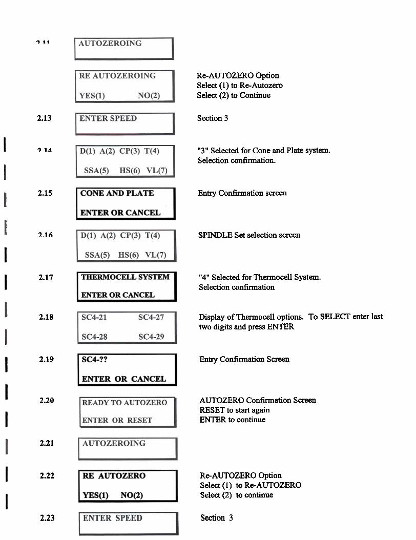
., 11
RE AUTOZEROING Re-AUTOZERO OptionSelect (1) to Re-AutozeroSelect (2) to ContinueNO(2)YES(l)
2.13 Section 3
? 1.d D(1) A(2) CP(3) T(4) "3" Selected for Cone and Plate system.Selection confinnation.
SSA(S) H8(6) VL(7)-
Entry Confirmation screen2.15 CONE AND PLATE
ENTER OR CANCEL
, 1" D(I) A(2) CP(3) T(4) SPINDLE Set selection screen
SSA(S) HS( 6) __~ffi
THERMOCELL SYSTEM2.17 "4" Selected for Thermocel1 System.Selection confinnation
ENTER OR CANCEL
2.18 SC4-21 SC4-27 Display of Thermocell options. To SELECT enter lasttwo digits and press ENTER
SC4-28 SC4-29
2.19 SC4-?? Entry Confimtation Screen
ENTER OR CANCEL
AUTOZERO Confimlation ScreenRESET to start againENTER to continue
2.20 I READY TO AUTOZERO
ENTER OR RESET
2.21
Re-AUTOZERO OptionSelect (1) to Re-AUTOZEROSelect (2) to continue
2.22 RE AUTO ZERO
NO(2)YES(l)
2.23 ENTER SPEED Section 3

2.24---
D(l) A(2) CP(3) T(4) Spindle Set selection screen
SSA(5) H8(6) VL(7)
2.25 SMALL SAMPLEADAPTOR
"5" SELECTED for Small Sample Adaptor.Selection confirmation screen
ENTER OR CANCEL
2.26 14/6R 15/7R 21/13R Display of ASTM style Small Sample Adaptoroptions.Enter the first two digits of choice, and press ENTER.27/13R 28/13R 29/13R
SC4-?? I??R Selection confimlation screen... I
ENTER OR CANCEL
2.28 READY TO AUTOZERO AUTOZERO confirmation screen.RESET to start againENTER to continueENTER OR RESET
2.29
2.30 RE AUTO ZERO Re-AUTOZERO optionSelect (1) to Re-AUTOZEROSelect (2) to ContinueYES(ll NO(2)
., '21 Section 3
D(I) A(2) CP(3) T(4) Spindle Set selection screen
SSA(S) H8(6) VL(7)
2.33 BELIPATB SYSTEM "6" Selected for Helipath system.
ENTER OR CANCEL Selection confinnation screen
2.34 T-A(l) T-B(2) T-C(3) Select numerical option of choice
T -D(~) T -E(5) T -F(6)
T-? Selection Confirmation screen
ENTER OR CANCEL

READY TO AUTOZERO AUTOZERO confinnation screenRESET to start againENTER to continue
2.36
ENTER OR CANCEL
IAUTOZEROING I2.37
2.38 RE AUTOZERO Re-AUTOZERO optionSelect (1) to Re-AUTOZEROSelect (2) to continueYES(l) NO(2)
Section 3
2.40 D(l) A(2) CP(3) T(4) Spindle set selection screen
SSA(5) HS(6) VL(7)
VERY LOW ADAPTOR "7" Selected for VL ADAPTOR,Selection con:finI1ation screen
ENTER OR CANCEL
2.42 Identifies that only one spindle exists in this system
2.43 READY TO AUTO ZERO AUTOZERO confinnation screenRESET to start againENTER to continueENTER OR CANCEL
2.44
2.45 RE AUTOZERO Re-AUTOZERO optionSelect (I) to Re-AUTOZEROSelect(2) to continueYE~~) ~~0-
Section 32.46
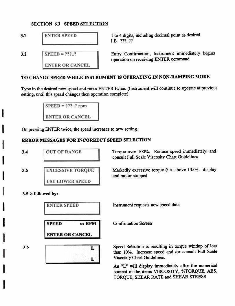
SECTION 6.3 SPEED SELECTION
1 to 4 digits, including decimal point as desired.I.E. m..??
3.1
SPEED = ???? Entry Confinnation, Instrument immediately beginsoperation on receiving ENTER command
3.2
ENTER OR CANCEL
TO CHANGE SPEED WHILE INSTRUMENT IS OPERATING IN NON-RAMPING MODE
Type in the desired new speed and press ENTER twice. (Instrument will continue to operate at previoussetting, until this speed changes then operation complete)
SPEED = ??? ..? rpm
ENTER OR CANCEL
On pressing ENTER twice, the speed increases to new setting.
ERROR MESSAGES FOR INCORRECT SPEED SELECTION
Torque over 100%. Reduce speed immediately, andconsult Full Scale Viscosity Chart Guidelines
3.4
Markedly excessive torque (i.e. above 135%. displayand motor stopped
3.5 EXCESSIVE TORQUE
USE LOWER SPEED
3.5 is followed by:-
Instrument requests new speed data
Confirmation ScreenSPEED xxRPM
ENTER OR CANCEL
Speed Selection is resulting in torque windup of lessthan 10%. Increase speed and lor consult Full ScaleViscosity Chart Guidelines.
3.6 L
LAn "L" will display immediately after the numericalcontent of the items VISCOSITY, %TORQUE, ABS,TORQUE, SHEAR RATE and SHEAR STRESS

3.7 Speed Selection is resulting in torque windup ofgreater than 90%. Decrease speed or consult FullScale Viscosity Chart Guidelines.
H
HA "H" will display immediately after the numericalcontent of the items VISCOSITY, % TORQUE, ABS,TORQUE, SHEAR RATE and SHEAR STRESS

SECTION ~.4 PRINT and RAMP Enro
4.1 PRINTER OUTPUT Initial Prompt Screen. Enter 1 or 2
YES(l) NO(2)Printer output selected
4.2 Time interval selected in the fonD of six digits.hhmm ss. Max :-235959 Min:-OOOOlO
ENTER PRINTER
TIME INTERVAL
4.3 ??h : ??m : ??s Confirmation of Selection
ENTER OR CANCEL
4.4 RAMPING
~(l) NO(2)
4.5 ENTER MAX SPEED Speed can be selected in I to 4 digits, with or withoutdecimal points as necessary.Max Speed = 500RPM
4.6 SPEED = 111..1 r .p.m. Confirmation Screen
ENTER OR CANCEL
4.7 ENTER MIN SPEED I to 4 digits, with or without decimal point asnecessary. Please note MIN cannot be entered asgreater than MAX
4.8 SPEED = ??? ..? r .p.m.
ENTER OR CANCEL
4.9 ENTER STEP SPEED 1 to 4 digits, decimal point as necessary. Please noteMAX-MIN must be divisible by STEP SPEED,Otherwise program will reject setting
SPEED = ??? .? Confirmation Screen
ENTER OR CANCEL
4.11I ENTER RAMP TIME MINUTES, in 2 digits.
MAX interval is 59 minutes. MIN interval is 01minutes (N.B. Entry must be at least 2 digits)I INTERV AL

4.12 MINUTES Ramp Time Interval confinnation screenx
ENTER OR CANCEL
4.13 UP(l) DOWN(2) Single direction or cycle
UP/DOWN(3)
previous selection Confirmation Screen
ENTER OR CANCEL
4.15 D(l) A(2) CP(3) T(4)
SSA(S) HS(6) VL(7)
Spindle type selection screenwhere:-
D = DIN typeA = ASTM typeCP = Cone and Plate systemT = Thermocell systemSSA = Small Sample AdaptorHS = Helipath Stand UnitVL = VL Adaptor
See Section 2 for selection procedures
4.16 X SPINDLE Spindle type confirmation screen.After selection procedure as described in Section 2
ENTER OR CANCEL
4.17 READY TO AUTO ZERO Final RESET option. Otherwise proceed
ENTER OR RESET
4.18 AUTOZEROING
4.19 RE AUTOZERO Re-AUTOZERO optionSelect (1) to Re-AUTOZEROSelect (2) to continueYES(l) NO(2)
VISCOSITY mPa.s RAMP in operation
TEMP. DEGC

After completion of a RAMP sequence the display will proceed as follows:-
4.21 REQUIRE ANOTHERRAMP
Option to initiate a further RAMP sequence
YES(l) NO(2)
4.22 IF NO(2) selected at 4.21. AUTOZERO optionpresented. YES(I) proceed to 4.23 below. i.e. return tostart.
REQUIRE AUTOZERO
YES(l) NO(2)NO(2) proceed to 4.24 only speed input requested
Return to opening screenYES(I) to the screen at 4.22.
4.23 PRINTER OUTPUT
YES(l) NO(2)
ENTER SPEED request. NO(2) to screen at 4.22.Instrument assumes no spindle change, asAUTOZERO not requested. Only SPEED data needed
ENTER SPEED

SECTION 6.5 RESETTING AFTER AUTOZERO
5.1 ENTER SPEED Following the completion of AUTOZERO on a non-RAMPing sequence.Press RESET
REQUIRE AUTOZERO Select I for re-AUTOZERO, go to Abelow.Select 2, go to B below
5.2
YES(l) ~~(2)
A.
5.3--
PRINTER OUTPUT The opening screen; As AUTOZERO was requestedthe Instrument asswnes that a spindle change isoccurring and gives full RAMP, SPINDLESELECTION screens, as in Section 4.
YES(l) NO(2)
B.
PRINTER OUTPUT Back to a special RESET Screen~.4
YES(l) NO(2)
5.5 RAMPING Full RAMP options. Select RAMP sequence(l) andthe Instrument will commence the selected RAMPwithout re-AUTOZEROING. Select NO. and theInstrument assumes that as no AUTOZERO wasrequested, or ramping was not required only input ofSPEED is necessary
YES(l) NO(2)
5.6 ENTER SPEED Return to screen as at 6.1
SECTION 6.6 SCREEN OPTIONS
6.1 Screen 1. Viscosity in milli paschal seconds andTemperature in Degrees Centigrade(with optionalRill Temperature Probe) to Scroll to Screen 2 PressAL T DISPLAY
VISCOSITY ???? mPa.s
TEMP +???? DegC
6.2 Screen 2. %Torque and Absolute Torque in DyneCentimetres. To Scroll to Screen 3,press AL T DISPLAY
% TORQUE ??? .?%
A TORQUE ??? . ?DY .CM.
S.R.6.3 ????E-?? lIS Screen 3. Shear Rate(S.R.) in Reciprocal Seconds, andShear Stress(S.S.) in Dynes per Square Centimetre,where appropriate given spindle selection andgeometry. If not derivable, display of Zero. To scrollto Screen 4, press ALT DISPLAY
s.s. ????E-??DY/CM2
6.4 Screen 4. Speed in RPM and confinnation of spindleselected. AL T DISPLAY scrolls back to Screen I
I SPEED ??? .?rpm
?? (Spindle) selected

The user will note that when printer output is selected the Viscometer will
print a record keeping section at the top of each experimental print ~
This handy filingcovering date, time, experiment code and side notes.
header is given after each Power-Up, RESET or at the commencement of
It iseach RAMP sequence.It is not repeated at each RAMP sequence.
not repeated at each speed change.
SPECIFICATIONS FOR STRIP CHART OUTPUT
Volt Output.Minimum allowable load resistance of 500 ohms..
CONNECTION
The strip chart recorder output from the viscometer is on the front Panel of
the Power Supply. The recorder output plug is inserted here.
DESCRIPTION AND USE
The strip chart recorder output voltage is proportional to the percent
.e. the engineering units "E" on thetorque wind up of the spring,
In calibrating the chart recorder use a knownviscometer display.
Newtonian or calibration fluid and ensure the display is set to engineering
The Percent torque wind up of the spring "E" is now directlyunits "E".
proportional to the speed setting. During a downward speed change it can
be noted that the Percent torque wind up of the spring decreases below
that expected for the new speed setting, then rises to a stable level. This is
a feature of the system design to reduce any natural hysteresis of the
spring.

TO CALCULATE VISCOSITY FROM A CHART READING AT A
LATER DATE
The viscosity can be calculated from the chart at a later date using chart
factors as follows
Given the speed and spindle combination in use during recording.1.
locate the appropriate full scale viscosity in the Full Scale Viscosity
Tables.
2. If this value is not in mPa.s, convert using:-
lO3mPa.sIPa 1,OOOmPa.s. =
lO6mPa.slKPa= 1,OOO,OOOmPa.s =
To calculate the chart factor, divide the full scale viscosity in mPa.s3.
by 100.
4. To calculate the viscosity in mPa.s corresponding to the chart
reading multiply the reading by the chart factor above.

EXAMPLE
For the M model~ set at 50 rpm. using spindle 3. and a chart reading of
47.21
1. Full Scale Viscosity = 2,000 mPa.s
2. Reading already in mPa.s.
3. Chart factor Full Scale Viscosity /100=
20
4. Viscosity Chart factor * chart reading=
20.47.21=
944.2 mPa.s=
Similarly. given other parametric reference data for the spindle system in
use, all other values can be calculated.

8.0 VISCOMETER TROUBLE SHOOTING
Snindle vibrates. instead of rotatine:A
Check if the cable between the power supply and viscometer is
tightly secured.
B Snindle rotates eccentrically
1 Spindle not screwed securely to coupling.
~ tighten.
2 Dirt on spindle connector ~ clean.
3 Bent spindle => check other spindles, replace as
necessary.
RH. Maximum permissible eccentricity is 1/16th(1.6mm) at end of spindle.
No Power =:) Check fuse in the mains cable, socket4.
at the back of the power supply. Ifreplacement fuse
blows return for servicing.
5 Erroneous readings
(i). Wrong spindle, or speed selected
=) change spindle or speed selection.
(ii). Forgot to AUTOZERO
=> remove spindle from fluid, detach it from
the viscometer, clean, replace and AUTOZERO.
(iii) Autozero occurred in fluid, or when Instrument
not fully at rest.
=> Autozero again, in air, with Instrument at rest
6. Display does not change
~ "HOLD" switch in ~ release

Your Rheology International SERIES 2 viscometer can be upgraded to
Follow theseComputer Control to further enhance your investment.
instructions for easy installation.
(A) Remove the Parallel Port PCB
Your viscometer has been factory installed with a parallel port to facilitate
the timed printer output.
(i) Unscrew the M3 pori drive counter sunk screw holding the "Front
Panel" in position, and remove. Allow the front panel to lie
forward. There is no need to remove the front panel from the
instrument.
(ii) Remove the two M3 screws holding the Parallel Port PCB in
position.
(iii) Remove the two hexagonal nuts holding the cable and socket in
position on the rear panel, marked printer.
(8) To Install the Computer Upgrade Serial Port
(i) Present the socket of the Serial port to the rear panel
(ii) Attach the socket to the rear panel using the two hexagonal screws as
they were for the Parallel Port.
(iii) Connect the Serial Port PCB to the mounting socket and hold in
place with the existing M3 screws.

C) D.I.L Switches on Mainboard
DOS Rheologic
ON 2 1,2,4 & 5Serial Port
OFF Rest Rest
Parallel 6 & 11 6& 11Port
ON
OFF Rest Rest

10.0 REPAIRS AND SERVICE
All Rheology International Viscometers requiring repair or service should be returned
to:
Rheology (International) Shannon Ltd.
Industrial Estate,
Shannon
Co. Clare.
ITel: +353 - 61 - 471334 Email: [email protected]
Fax: +353 - 61 - 471042
The Viscometer should be shipped in its carrying case together with all the spindles
originally provided with the instrument.
WARRANT Y
All Viscometers are guaranteed free from design faults, materials failures, and faulty
workmanship for a period of one year from date of purchase. The Viscometer must be
returned to the manufacturer or National Distributor for no charge warranty service.
Transportation is at users expense.

CIRCUIT BOARD SCHEMATIC RI 2 MAIN BOARD
TEMPERATUREZERO
TEMPERATURESETINGS
CHARTRECORDER
VISCOMETERSETTING
AUTO ZERO
FIGURE
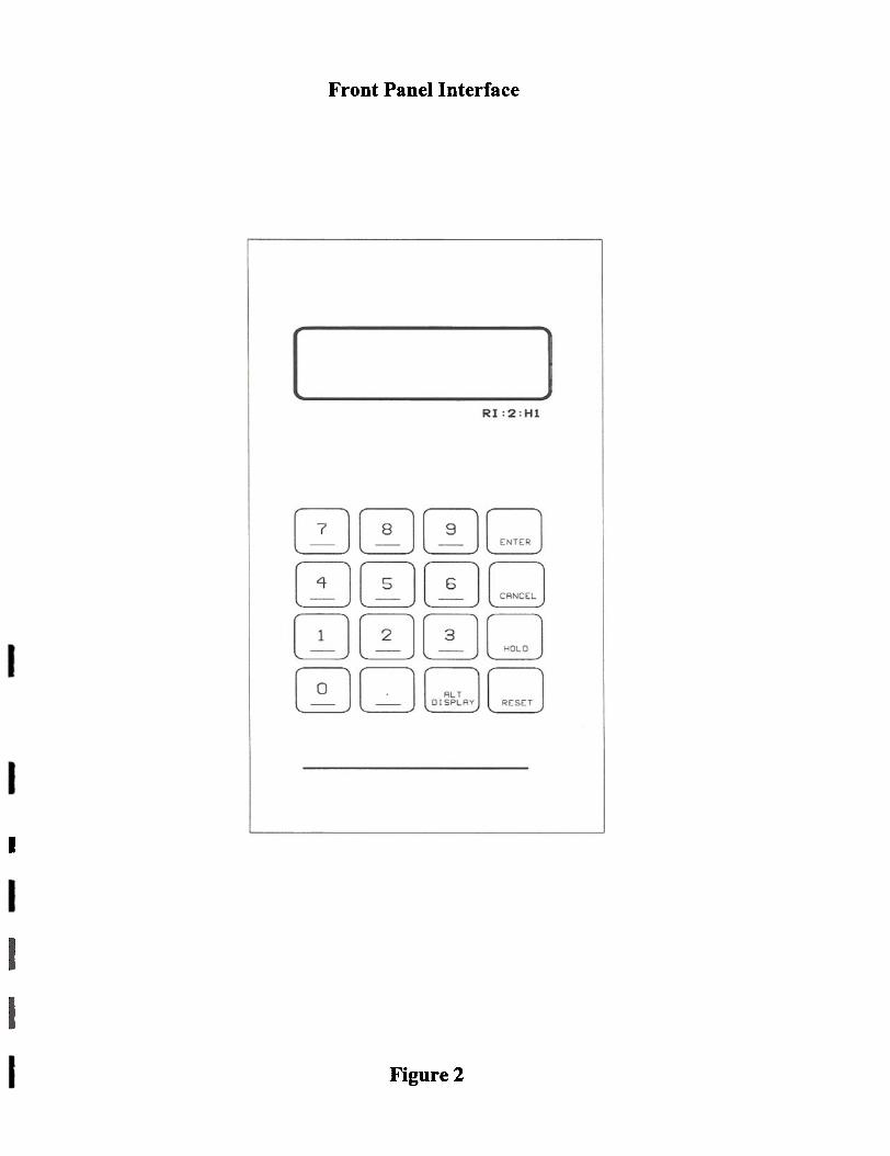
Front Panel Interface
I
Figure 2

Assembly Schematic
Figure 3


~00-<N=..N..
;~u~0u00>~u00g
;: ';;'
~
.-
.~
~
.s e
=.
-~
~
0 -
8-q-
~
0 0
'""
I-q--
--~O
'""1.0 r--. ~
0\
o~
N
1.0 -~
~
~
i-
- -
N 0 \0 0 - f"\ 0 0 t- 0 0 8801
Oll"lot-f"\O
O\O
ooI
<"i-
'I').. o~
'I').. f"\~
.q-~
o~
\O
~
o~
o~
o~
0f"\ f"\ .q- .q- 11"1 \0 00 0 \0 ~
.q- 01
--f"\\O~
~...,I
~
i ~
\O~
d
- .~
.
]!=:a
cE .!
Q)
rn
"Q~
~
.s~8
-<o~
~.8
~
~-S
~.~
..8'~-
~e
~~
.o
~
!8
~
~~
ff'I -jZ
rn
~~
.(~s~~
~~
0 8
0 ..fJ
~~
~
Q
)
-8 .S
'>
rn
-.a~~ 8-
1~~~
~~
~"0 ~
... .
0 ~
~