rhic p-carbon polarimeter target lifetime issue · the nature of the light (black body radiation or...
TRANSCRIPT

RHIC p-CARBON POLARIMETER TARGET LIFETIME ISSUE∗
H. Huang, I.G. Alekseev, E. Aschenauer, G. Atoian, A. Basilevsky, K.O. Eyser, A. Fernando,D. Gassner, D. Kalinkin, J. Kewisch, G. Mahler, Y. Makdisi, S. Nemesure, A. Poblaguev,
W. Schmidke, D. Steski, D. Svirida, T. Tsang, K. Yip, A. ZelenskiBrookhaven National Laboratory, Upton, NY 11973, USA
AbstractRHIC polarized proton operation requires fast and reliable
proton polarimeter for polarization monitoring during stores.Polarimeters based on p-Carbon elastic scattering in theCoulomb Nuclear Interference(CNI) region has been used.Two polarimeters are installed in each of the two colliderrings and they are capable to provide important polarizationprofile information. The polarimeter also provides valuableinformation for polarization loss on the energy ramp. As theintensity increases over years, the carbon target lifetime isgetting shorter and target replacement during operation isnecessary. Simulations and experiment tests have been doneto address the target lifetime issue. This paper summarizesthe recent operation and the target test results.
INTRODUCTIONThe collision of polarized proton beams at RHIC (at up
to√
S = 510 GeV energy) provides a unique physics op-portunity for studying spin effects in hard processes at highluminosities, including the measurement of the gluon polar-ization and the quark and anti-quark spin flavor composition.RHIC is the first polarized proton collider where the
Siberian snakes were successfully implemented to maintainpolarization during beam acceleration [1]. The fast polar-ization measurements are critical for the accelerator setupand physics programs during the physics stores. The pCCNI polarimeters in RHIC are based on elastic proton scat-tering with low momentum transfer in the CNI region andmeasurement of asymmetry in recoil carbon nuclei produc-tion [2]. This process has a large cross-section and sizableanalyzing power of a few percents which has weak energydependence in the 24-255 GeV energy range. A very thin(5-10 µg/cm2, 5-10 µm wide) carbon ribbon target in thehigh intensity circulating beam produces high collision rateand a highly efficient DAQ system acquires up to 5 × 10⁶carbon events /sec. The absolute beam polarization was mea-sured with a polarized H-jet polarimeter which is also basedon elastic proton-proton scattering in the CNI region [3].These calibration measurements have been done at variousenergies, such as 24 GeV, 31 GeV, 100 GeV, 250 GeV and255GeV. The results showed weak energy dependence, es-pecially above 100 GeV. The simultaneous measurementsin pC and H-jet polarimeters provide the calibration for pCpolarimeter analyzing power. A typical store would resulta ±3% statistical error in the polarized jet measurement.The fast pC polarimeter measures polarization profiles in∗ Work performed under contract No. DE-AC02-98CH1-886 with theauspices of the DOE of United States
both transverse planes, which are used to derive the polariza-tion at collision points for experiments. The pC polarimeteralso measures possible polarization losses during the energyramp and possible polarization decay during the RHIC store.
POLARIMETER ASSEMBLYRHIC polarimeters have evolved in past ten years [4].
Two identical polarimeter vacuum chambers are located inthe warm RHIC sections which are separated for the tworings and have the separate vacuum systems. Due to thecomplexity of the chamber and the electronics, it is not prac-tical to bake the chamber. A non-evaporable getter cartridgepump is added to each chamber to provide additional contin-uous pumping. As a result, the pump down speed is greatlyimproved, which allows the target replacement during main-tenance day. A full intensity physics store can be resumedwithin 24 hours (vacuum down to 10−9 Torr).
It is desirable for the polarimeter to measure both horizon-tal and vertical beam polarization profiles, which requiresseparate targets scanning both vertically and horizontally.Since the thin carbon target has a relative short lifetime atthe full RHIC beam luminosity, it would be advantageous tomount multiple targets on the driving mechanism (spaced sothat the beam sees one ribbon at a time) to extend the timebetween maintenance periods. Each polarimeter consists ofsix horizontal targets and six vertical targets. Simulationshows that the expected equilibrium temperature at 255 GeVwith full loaded intensity (2.4×10¹³) for a typical carbonribbon target would be around 1800K. It is generally inad-visable to run the fiber at temperatures exceeding 2000K,which is the onset of thermionic emission, since this wouldshorten the lifetime of the fiber.The large aspect ratio of the thin carbon target (2.5 cm
long, 10 µm wide and 25-50 nm thick) is essential for po-larization measurement. First, it increases heat dissipationrate so that the target can survive the high intensity beam.Second, it reduces multiple scattering for recoil carbon ionsand also keep the event rate within the detectors and DAQcapabilities. However, the ultra thin target is very fragileand has limited lifetime. Good targets survive in the RHICbeam for 50-100 measurements at the full beam intensityand 255GeV. The ultra-thin carbon target production pro-cedure was developed at Indiana University [5] and it is aroutine now at BNL [6]. The target positioning accuracy isabout ±0.5mm and limited by the target straightness. Theaccuracy is required due to limited detector acceptance.
The time-of-flight and recoil carbon energymeasurementsare required for elastic scattering identification. The silicon-
MOPD01 Proceedings of IBIC2014, Monterey, CA, USA
ISBN 978-3-95450-141-0124Co
pyrig
ht©
2014
CC-B
Y-3.
0an
dby
ther
espe
ctiv
eaut
hors
Collider Specific Instrumentation

strip detectors are used in the polarimeters since they allowmeasurements of energy and arrival time of Carbons in theRHIC ring vacuum environment. The late arrival time ofthe recoiled carbons is advantageous since the detection canbe done with much less noise after all beam-induced distur-bances are gone. In addition to one pair of detector sitting inthe horizontal plane, two pairs of detectors sitting at 45 areadded, which allow measurement of both vertical and radialpolarization components. At full RHIC designed intensity,the rms bunch length is about 2 ns and bunch spacing is106 ns. To avoid the prompt background, the carbon nucleishould arrive the detectors between two bunches. The Sidetector can detect carbons with kinetic energy as low as200 keV, which can travel about 20 cm in 100 ns. The dis-tance between detectors and interaction point is set as 18 cm.There are RF shields at the surface of the chamber to coverthe detector ports to reduce the impedance impact [7].The preamplifier boards are mounted on the polarime-
ter vacuum chamber and directly connected to the vacuumfeedthroughs to minimize the distance to the signal source.The amplified analogue signals are transferred through theRHIC tunnel on coaxial cables for about 90 m to a countingroom located next to the tunnel. A wave form digitizer isutilized in the DAQ to handle the high-rate and minimizedead-time.
TARGET LIFETIME ISSUESUsually, a good carbon target breaks after usage of 50
to 100 times. But the variation of target lifetime is relativelarge: many targets have been lost before seeing beam, orjust broke after a few uses. This is especially the case whena target was lost at store, and a new target has to be usedright away. Polarimeter chamber has to be opened to replacetargets during maintenance day twice in past two polarizedproton operations. The broken targets were checked undermicroscope. About 2/3 of the broken targets were brokennear the ends. The rest 1/3 were broken near the center.A lot efforts were put in to understand the mechanism forthe target breakage. It was found that the targets survivedbeam operation are graphitized and have smaller resistances,about a few MΩ while the resistance of unexposed targets isa few hundreds MΩ. It was also found that the exposure toflash light can greatly reduce the target resistance. About 1/3targets used in run13 were exposed to high power flash lightto reduce the resistance. Since some new targets lost at storein first a few uses, one hypothesis is that the targets need tobe “conditioned” with modest beam intensity before using atstore energy. This is the similar effect as the high power flash,but probably more powerful. In run13, all targets have beenused first at injection with gradually increased total intensi-ties: 0.5, 1 and 2×10¹³. Then they were put into use at store.However, this effort did not yield significant improvementin the target lifetime. The target temperature is expected tobe around 1500-2000K, visible light emission is expectedat these temperatures. The polarimeter target chamber hasseveral viewports to check targets during maintenance day.
Figure 1: A glowing target when crossing beam. The centralbright spot is due to beam.
Figure 2: A target with glowing ends when it is off beam.Note that the nearby target end (on the right side) is alsoglowing in the dark. Due to the limited aperture, the cameracan not cover more targets.
A few cameras were installed to take video when targetscrossing beam. The observation surprised all of us. Theglowing light was brightest when the target crossed the beamcenter. This is understandable, as beam heating generateshigh temperature and black body radiation could be the mainsource of the glowing light from target portion hit by beam.In addition, the ends glow when the beam is far away (a fewcm) from the target. Figure 1 showed the captured pictureof a glowing target when it crossed the beam center. Fig-ure 2 is when target was far away from beam and at parkposition, where the target sat for hours between polarizationmeasurements. The persistent glowing over a store (8-10hours) could be a source of relative short target lifetime forthese targets.
Light filters with different spectrum ranges were put intoone camera. The idea was to get the relative strength of thelight emission at different wave length ranges. Comparingwith black body radiation power distribution, one can get
Proceedings of IBIC2014, Monterey, CA, USA MOPD01
Collider Specific InstrumentationISBN 978-3-95450-141-0
125 Copy
right
©20
14CC
-BY-
3.0
and
byth
eres
pect
ivea
utho
rs

the nature of the light (black body radiation or not) andthe temperature. The glowing light spectrum at the targettails when crossing the beam or at park position does notconsistent with black body radiation. But to make detailspectral analysis, a spectrometer is needed.One possible mechanism to explain the glowing target
tails is the induced electric-magnetic fields due to the beampassing by. The target chamber is like a RF cavity and thetarget frame is like an antenna. The induced high frequencyelectrical fields move electrons back and forth along thetarget frame as weel as targets. Heat is generated due to theresistance of the targets, which in turn causes black bodyradiation and emit lights.At store energy(250 or 255 GeV), the high frequency
RF cavities (200 MHz) were turned on to generate shorterbunches for luminosity gain. The high peak current associ-ated with the short bunches should make the glowing worse.Indeed, the 200 MHz cavity was ramped to lower value andthe glowing light disappeared. This observation is consis-tent with the induced field hypothesis, as higher peak currentwith higher 200 MHz cavity voltage is expected to inducestronger electric fields. In run13, the 200 MHz cavity volt-age was ramped down during the polarization measurements.This procedure not only reduced the glowing light, but alsoreduced the electronic noises in the preamp circuitry. Theramping down 200 MHz cavity voltage only reduces thelight during measurements when the effect is strongest. Thetarget glowing at park position is still a problem. Due to thespace constraint, only half of the targets can be parked farenough from the beam. The other half targets have to endurethe chronic effect of the induced electric-magnetic fieldsthroughout the stores. These targets indeed have shorterlifetime compared to the other half which could be parkedfurther away. To prolong the target lifetime for these halfand probably to all targets, something needs to be done.
SIMULATION OF TARGET HEATINGIf the problem is due to the induced electric-magnetic
fields, the effect should be proportional to the electric fieldsalong the target wire. One possible solution is to providesurface for the field lines to “spread out”. These surfaceshould have smooth curvature to avoid sharp edges. Onedesign is to add fins to both ends of the target frame. Ingeneral, the larger the surface, the larger the reduction, butthe fins must fit into the limited space in the tank and theclearance from the target-beam interaction region to the Sidetectors have to be maintained, too.
The simulations were done with CST-studio [8]. The realmechanical drawing of the polarimeter chamber (as shownin Fig. 3) was used in the simulation. The peak current ofbeam is used in the simulation. Three cases of target relativeto beam positions were simulated: the first one was when atarget crossing the beam center; the second and third oneswere when all targets were away from the beam by 2.5 cmtransversely at either inner or outer positions. There was notmuch difference in the last two cases.
Figure 3: The 3D drawing of the polarimeter chamber. Thetape structure (5:1) is to reduce the impedance impact on theoverall RHIC ring impedance budget. The two view ports onboth tape structure are used to monitor the target operation.The big view port on the top is for target installation. Threecameras are mounted on these view ports to monitor thepolarimeter target operation. There are two sets of six Sidetectors ports surrounding the chamber on both sides ofthe big view port. There are vertical and horizontal targetsfor each set.
Figure 4: The detail of one horizontal target assembly. Thevertical target assembly(the smaller hole at the bottom) wasnot included in the simulation.
Figure 5: The details of the target frame fins. The shape isdesigned to have smooth curvature and enough clearancein the chamber. The half elliptical shape allows it to bemounted on every target, but a full elliptical shape shouldreduce the electric fields further.
MOPD01 Proceedings of IBIC2014, Monterey, CA, USA
ISBN 978-3-95450-141-0126Co
pyrig
ht©
2014
CC-B
Y-3.
0an
dby
ther
espe
ctiv
eaut
hors
Collider Specific Instrumentation

0 0.5 1 1.5 2 2.5 3 3.5 4 4.5Distance [inches]
-3e+07
-2e+07
-1e+07
0
1e+07
2e+07
3e+07
E fie
ld [V
/m]
xyzx no finsy no finsz no fins
Figure 6: The simulated electric fields when target is in thecenter of beam (at 0.5 in location). Here z is along beammoving direction, y is the vertical direction and x is radialout direction. The solid lines are for the case with fins andthe dashed lines are for the case without fins.
In each case, the target with and without fins (as shown inFig. 5) were simulated to see the effects. Note that the finsare in half elliptical shape and a slit in the middle allows itto be pushed into place. As Fig. 6 shows, the electric fieldsare very strong near the end of the target frames, even forthe targets which are not in the beam. Further more, Fig. 7shows that the electric fields are strong even when all targetsare out of beam. These simulation results are consistentwith the observation shown in Figs. 1-2, where the glowinglight is visible for the target ends in the beam or out of beam.By comparing Figs. 6 and 7, it seems that the fields at alltarget ends are similar for both in and out of beam cases.The simulations suggest that the lifetime of targets not inuse could be shortened. This was also consistent with theobservation. As expected, the simulation results showed thatthe electric fields at the edge of target frames were greatlyreduced for the case with fins. The reduction factor is about10-20.
EXPERIMENTAL RESULTSThere was no polarized proton beam planned for 2014
and this also provided an opportunity to test the modificationof target frame with other beams. Targets mounted on theframes with and without fins have been installed before therun started. To save time, a round shape aluminum fins wereused (as shown in Fig. 8). It should have stronger effectthan half elliptical one. Due to its shape, only four out ofsix target positions have the required clearance. A bunch oftargets with and without fins were installed.
Both Au and He ion beams were used this year to comparethe targets with and without fins. There is no chance for acarbon target to survive Au beam crossing. Instead, targetswere put about 1.5 cm away from beam center at end ofphysics store. The glowing light is definitely stronger for
0 0.5 1 1.5 2 2.5 3 3.5 4 4.5Distance [inches]
-3e+07
-2e+07
-1e+07
0
1e+07
2e+07
3e+07
E fie
ld [V
/m]
xyzx no finsy no finsz no fins
Figure 7: The simulated electric fields when target is out ofbeam. The coordinate system is the same as in Fig. 6.
Figure 8: The fin used in the experiment test.
target frames without fins. Figs. 9 and 10 clearly showedthe effect. When the targets were moved away from beamby more than 3 cm, the light disappeared for both type oftargets. Unfortunately, due to the limiting space inside thepolarimeter chamber, about half of the targets can not beparked that far from beam. Additional protections are neededfor these targets.
Different Au beam peak current was used to compare thetwo type targets. The light is dimmer with smaller peak cur-rent. In all cases, the targets with fins have weaker glowinglight. The voltage of 200 MHz RF cavity was also rampeddown from 650 kV to 100 kV. The light disappeared for bothtargets with and without fins. This is expected, as the lowervoltage corresponds to lower peak current. The inducedelectric fields are strongly peak current dependent.For He beam, the charge is small enough, so that the
carbon target can cross the beam and survive. The peakcurrent for He beam is twice as high as Au beam. Duringthe test, there was no glowing light from the ends of thetargets with fins. Unfortunately, the targets without finswere broken during the target switching while all targetswere outside beam. Two big light flashes were seen. It was
Proceedings of IBIC2014, Monterey, CA, USA MOPD01
Collider Specific InstrumentationISBN 978-3-95450-141-0
127 Copy
right
©20
14CC
-BY-
3.0
and
byth
eres
pect
ivea
utho
rs
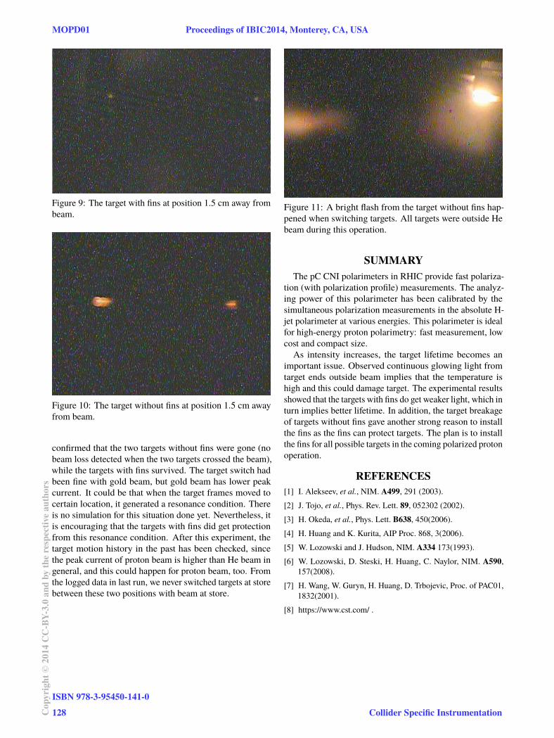
Figure 9: The target with fins at position 1.5 cm away frombeam.
Figure 10: The target without fins at position 1.5 cm awayfrom beam.
confirmed that the two targets without fins were gone (nobeam loss detected when the two targets crossed the beam),while the targets with fins survived. The target switch hadbeen fine with gold beam, but gold beam has lower peakcurrent. It could be that when the target frames moved tocertain location, it generated a resonance condition. Thereis no simulation for this situation done yet. Nevertheless, itis encouraging that the targets with fins did get protectionfrom this resonance condition. After this experiment, thetarget motion history in the past has been checked, sincethe peak current of proton beam is higher than He beam ingeneral, and this could happen for proton beam, too. Fromthe logged data in last run, we never switched targets at storebetween these two positions with beam at store.
Figure 11: A bright flash from the target without fins hap-pened when switching targets. All targets were outside Hebeam during this operation.
SUMMARYThe pC CNI polarimeters in RHIC provide fast polariza-
tion (with polarization profile) measurements. The analyz-ing power of this polarimeter has been calibrated by thesimultaneous polarization measurements in the absolute H-jet polarimeter at various energies. This polarimeter is idealfor high-energy proton polarimetry: fast measurement, lowcost and compact size.As intensity increases, the target lifetime becomes an
important issue. Observed continuous glowing light fromtarget ends outside beam implies that the temperature ishigh and this could damage target. The experimental resultsshowed that the targets with fins do get weaker light, which inturn implies better lifetime. In addition, the target breakageof targets without fins gave another strong reason to installthe fins as the fins can protect targets. The plan is to installthe fins for all possible targets in the coming polarized protonoperation.
REFERENCES[1] I. Alekseev, et al., NIM. A499, 291 (2003).[2] J. Tojo, et al., Phys. Rev. Lett. 89, 052302 (2002).[3] H. Okeda, et al., Phys. Lett. B638, 450(2006).[4] H. Huang and K. Kurita, AIP Proc. 868, 3(2006).[5] W. Lozowski and J. Hudson, NIM. A334 173(1993).[6] W. Lozowski, D. Steski, H. Huang, C. Naylor, NIM. A590,
157(2008).[7] H. Wang, W. Guryn, H. Huang, D. Trbojevic, Proc. of PAC01,
1832(2001).[8] https://www.cst.com/ .
MOPD01 Proceedings of IBIC2014, Monterey, CA, USA
ISBN 978-3-95450-141-0128Co
pyrig
ht©
2014
CC-B
Y-3.
0an
dby
ther
espe
ctiv
eaut
hors
Collider Specific Instrumentation