rhode and schwarz technology day - digitimes-首頁€¦ · rhode and schwarz technology day kwang...
TRANSCRIPT

Rhode and SchwarzTechnology Day
Kwang Meng KohRegional ManagerCustomer Solutions for WirelessTerminals
LTE Advanced

Evolution of Test Equipment to easy to use Multi purpose instruments
Wireless Technologies and Connectivity
Applications converging into one device with ubiquitous connectivity
eHealth
AugmentedReality
Interactive Gaming
Content:Music, Video, eBooks
eCommerceSocial Networks
Voice
Wireless EvolutionR&S has been the frontrunner in T&M during the evolution of wireless communication
CMU CMW

Mobile Data Traffic Growth and TrendsMobile Video / Global Forecast by Region
Mobile Video will Generate 70% of theMobile traffic by 2016
Asia Pacific and Western EuropeAccount over half of Mobile traffic
by 2016
Ref : CISCO VNI mobile 2012

Q2/2012: 27.6 million LTE subscriptions worldwide
LTE status

November 2012 | LTE and Beyond – LTE Advanced | 5
LTE Market - Commercial deployments
A truly global technology coveringboth FDD and TDD modes
96 LTE network are launched and shows that LTE is a fast growing global technology

November 2012 | LTE and Beyond – LTE Advanced | 6
The LTE eco-system is establishedLTE Devices: 417 products launchedl Number of
manufacturersannouncing LTEdevices grew 60%over past year
l Number of LTEsmart phones hasgrew 73% this year

2013/20142009/2010
Technology evolution pathGSM/GPRS
EDGE, 200 kHzDL: 473 kbpsUL: 473 kbps
EDGEevoDL: 1.9 MbpsUL: 947 kbps
HSDPA, 5 MHzDL: 14.4 MbpsUL: 2.0 Mbps
HSPA, 5 MHzDL: 14.4 MbpsUL: 5.76 Mbps
HSPA+, R7DL: 28.0 MbpsUL: 11.5 Mbps
2005/2006 2007/2008 2011/2012
HSPA+, R8DL: 42.0 MbpsUL: 11.5 Mbps
cdma2000
1xEV-DO, Rev. 01.25 MHzDL: 2.4 MbpsUL: 153 kbps
1xEV-DO, Rev. A1.25 MHzDL: 3.1 MbpsUL: 1.8 Mbps
1xEV-DO, Rev. B5.0 MHzDL: 14.7 MbpsUL: 4.9 Mbps
HSPA+, R9DL: 84 MbpsUL: 23 Mbps
DO-AdvancedDL: 32 Mbps and beyondUL: 12.4 Mbps and beyond
LTE-Advanced R10DL: 1 Gbps (low mobility)UL: 500 Mbps
Fixed WiMAXscalable bandwidth1.25 … 28 MHztypical up to 15 Mbps
Mobile WiMAX, 802.16eUp to 20 MHzDL: 75 Mbps (2x2)UL: 28 Mbps (1x2)
Advanced MobileWiMAX, 802.16mDL: up to 1 Gbps (low mobility)UL: up to 100 Mbps
VAMOSDouble SpeechCapacity
HSPA+, R10DL: 84 MbpsUL: 23 Mbps
LTE (4x4), R8+R9, 20MHzDL: 300 MbpsUL: 75 Mbps
WCDMADL: 2.0 MbpsUL: 2.0 Mbps
November 2012 | LTE and Beyond – LTE Advanced | 8
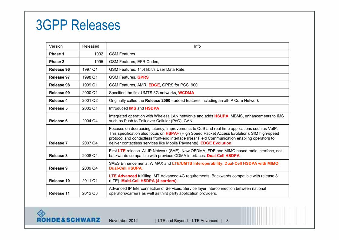
3GPP Releases
Advanced IP Interconnection of Services. Service layer interconnection between nationaloperators/carriers as well as third party application providers.2012 Q3Release 11
LTE Advanced fulfilling IMT Advanced 4G requirements. Backwards compatible with release 8(LTE). Multi-Cell HSDPA (4 carriers).2011 Q1Release 10
SAES Enhancements, WiMAX and LTE/UMTS Interoperability. Dual-Cell HSDPA with MIMO,Dual-Cell HSUPA.2009 Q4Release 9
First LTE release. All-IP Network (SAE). New OFDMA, FDE and MIMO based radio interface, notbackwards compatible with previous CDMA interfaces. Dual-Cell HSDPA.2008 Q4Release 8
Focuses on decreasing latency, improvements to QoS and real-time applications such as VoIP.This specification also focus on HSPA+ (High Speed Packet Access Evolution), SIM high-speedprotocol and contactless front-end interface (Near Field Communication enabling operators todeliver contactless services like Mobile Payments), EDGE Evolution.2007 Q4Release 7
Integrated operation with Wireless LAN networks and adds HSUPA, MBMS, enhancements to IMSsuch as Push to Talk over Cellular (PoC), GAN2004 Q4Release 6
Introduced IMS and HSDPA2002 Q1Release 5
Originally called the Release 2000 - added features including an all-IP Core Network2001 Q2Release 4
Specified the first UMTS 3G networks, WCDMA2000 Q1Release 99
GSM Features, AMR, EDGE, GPRS for PCS19001999 Q1Release 98
GSM Features, GPRS1998 Q1Release 97
GSM Features, 14.4 kbit/s User Data Rate,1997 Q1Release 96
GSM Features, EFR Codec,1995Phase 2
GSM Features1992Phase 1
InfoReleasedVersion

November 2012 | LTE and Beyond – LTE Advanced | 9
LTE Release 8FDD / TDD
DL UL
DL UL
The LTE evolutionRel-10
SONenhancements
CarrierAggregation
MIMO 8x8 MIMO 4x4EnhancedSC-FDMA
eICIC
Rel-9
eMBMS
PositioningDual Layer
Beamforming
Multi carrier /Multi-RAT
Base Stations
Home eNodeB
Self OrganizingNetworks
Public WarningSystem
Public WarningSystem
eMBMS
Public WarningSystem
Positioning
eMBMS
Public WarningSystem
Dual LayerBeamformingPositioning
eMBMS
Public WarningSystem
Home eNodeBDual LayerBeamformingPositioning
eMBMS
Public WarningSystem
Multi carrier /Multi-RAT
Base Stations
Home eNodeBPositioning
eMBMS
Public WarningSystem Self Organizing
Networks
Multi carrier /Multi-RAT
Base Stations
Home eNodeBPositioning
eMBMS
Public WarningSystem

November 2012 | LTE and Beyond – LTE Advanced | 10
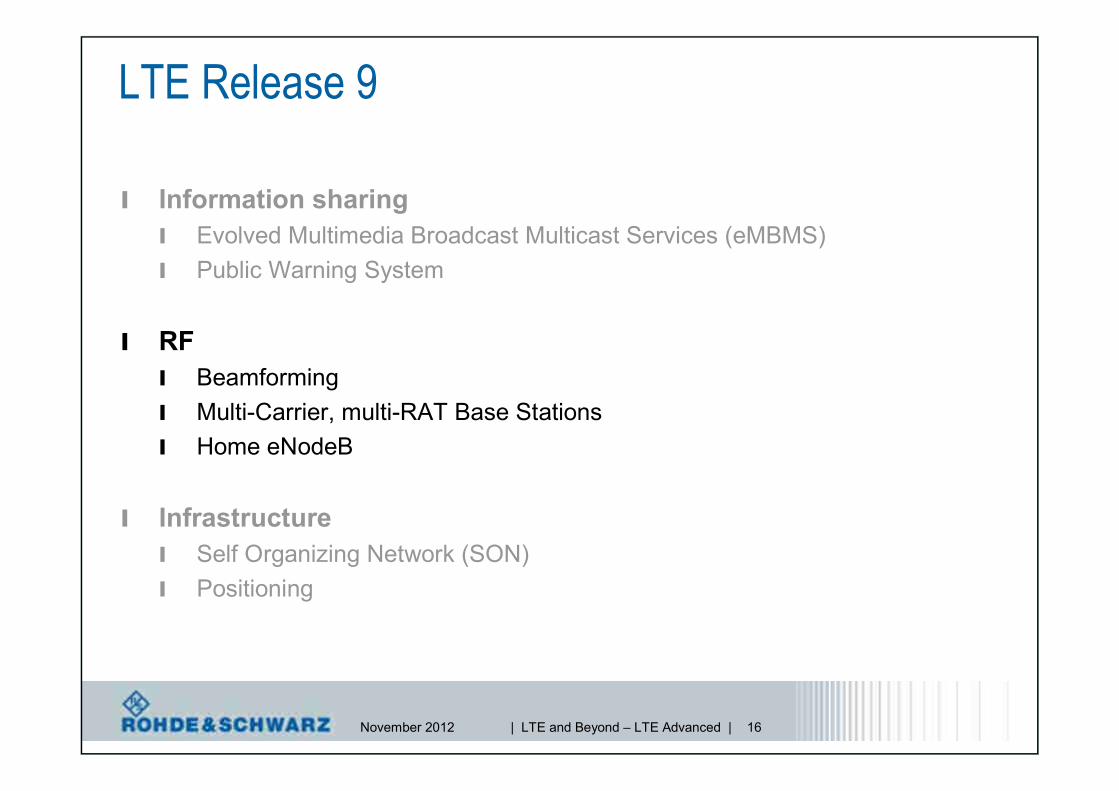
LTE Release 9
l Information sharingl Evolved Multimedia Broadcast Multicast Services (eMBMS)l Public Warning System
l RFl Beamformingl Multi-Carrier, multi-RAT Base Stationsl Home eNodeB
l Infrastructurel Self Organizing Network (SON)l Positioning

November 2012 | LTE and Beyond – LTE Advanced | 11
LTE Release 9
l Information sharingl Evolved Multimedia Broadcast Multicast Services (eMBMS)l Public Warning System
l RFl Beamformingl Multi-Carrier, multi-RAT Base Stationsl Home eNodeB
l Infrastructurel Self Organizing Network (SON)l Positioning
November 2012 | LTE and Beyond – LTE Advanced | 12
LTE Release 9evolved Multimedia Broadcast Multicast Services (eMBMS)
l MBMS is not new, it has been first specified with 3GPP Release 6 for2G and 3G (never successful)
l MBMS vs eMBMSl MBMS offers 6 TV channels at 128 kbps in 5Mhz BW (3G)l eMBMS offers 20 TV channels at 256 kbps in 5Mhz BW (LTE)
l eMBMS target to improve cell coverage and low power comsumptionl Mix of unicast / point-to-point transmissions
l Is the arrival of new devices (tablets, smartphones) changing thesituation?

November 2012 | LTE and Beyond – LTE Advanced | 13
l MCE coordinates the use of same radio resources andtransmission parameters across all cells belonging to theMBSFN area.
MCE
MBMSGW
M1
M3
User planeinterface
Control planeinterface between
E-UTRAN and EPC
E-UTRAN internalcontrol interface
MME
BM-SC – Broadcast/Multicast Service CenterMME – Mobility Management EntityMBMS GW – MBMS GatewayMCE – Multi-cell/Multicast Coordination EntityeNode B – LTE base station
BMSC
ContentProvider
M2
IP-Multicast
eNodeB
eNodeB
eNodeB
LTE Release 9evolved Multimedia Broadcast Multicast Services (eMBMS)
November 2012 | LTE and Beyond – LTE Advanced | 14
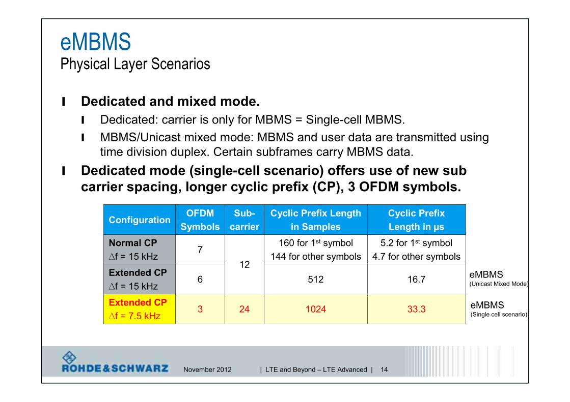
eMBMSPhysical Layer Scenarios
l Dedicated and mixed mode.l Dedicated: carrier is only for MBMS = Single-cell MBMS.l MBMS/Unicast mixed mode: MBMS and user data are transmitted using
time division duplex. Certain subframes carry MBMS data.l Dedicated mode (single-cell scenario) offers use of new sub
carrier spacing, longer cyclic prefix (CP), 3 OFDM symbols.
24
12
Sub-carrier
33.310243Extended CP∆f = 7.5 kHz
16.75126Extended CP∆f = 15 kHz
5.2 for 1st symbol4.7 for other symbols
160 for 1st symbol144 for other symbols
7Normal CP∆f = 15 kHz
Cyclic PrefixLength in µs
Cyclic Prefix Lengthin Samples
OFDMSymbols
Configuration
eMBMS(Single cell scenario)
eMBMS(Unicast Mixed Mode)

November 2012 | LTE and Beyond – LTE Advanced | 15
LTE Release 9Public Warning System (PWS)l Extend the Warning System support of the E-UTRA/E-UTRAN beyond
that introduced in the Release 8 ETWS (Earthquake and TsunamiWarning System) by providingl E-UTRA/E-UTRAN support for multiple parallel Warning Notificationsl E-UTRAN support for replacing and canceling a Warning Notificationl E-UTRAN support for repeating the Warning Notification with a repetition
period as short as 2 seconds and as long as 24 hoursl E-UTRA support for more generic “PWS” indication in the Paging Indication
l The requirement is to extend the UE RRC ETWS broadcast receptionmechanism and the associated paging mechanism to accommodatereception of CMAS (Commercial Mobile Alert System) alerts containedin a CBS message.
l New: TS 22.268 Public Warning System (PWS) Requirements (Release 9)
November 2012 | LTE and Beyond – LTE Advanced | 16
LTE Release 9
l Information sharingl Evolved Multimedia Broadcast Multicast Services (eMBMS)l Public Warning System
l RFl Beamformingl Multi-Carrier, multi-RAT Base Stationsl Home eNodeB
l Infrastructurel Self Organizing Network (SON)l Positioning

November 2012 | LTE and Beyond – LTE Advanced | 17
LTE Release 9Dual-layer beamformingTransmission modes in LTE Release 9

November 2012 | LTE and Beyond – LTE Advanced | 18
LTE Release 9Dual-layer beamforming
l 3GPP Rel-8 – Transmission Mode 7 = beamforming with no UEfeedback, using UE-specific reference signal pattern,l Estimate the position of the UE (Direction of Arrival, DoA),l Pre-code digital baseband to direct beam at direction of arrival,l BUT single-layer beamforming, only one codeword (TB),
l 3GPP Rel-9 – Transmission Mode 8 = beamforming with no UEfeedback, using UE-specific reference signal pattern, but dual-layer,l Mandatory for TDD, optional for FDD,l 2 (new) reference signal pattern for two new antenna ports 7 and 8,l New DCI format 2B to schedule transmission mode 8,l Performance test in 3GPP TS 36.521 Part 1 (Rel-9) are adopted to support
testing of transmission mode 8.

November 2012 | LTE and Beyond – LTE Advanced | 19
Dual-layer BeamformingNew DCI format 2B
November 2012 | LTE and Beyond – LTE Advanced | 20
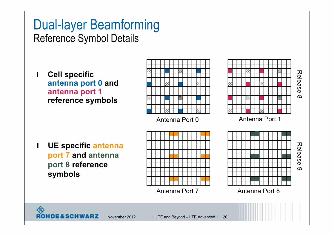
Dual-layer BeamformingReference Symbol Details
l Cell specificantenna port 0 andantenna port 1reference symbols
Antenna Port 0 Antenna Port 1
Antenna Port 7 Antenna Port 8
l UE specific antennaport 7 and antennaport 8 referencesymbols
Release
8R
elease9

November 2012 | LTE and Beyond – LTE Advanced | 21
Beamforming

November 2012 | LTE and Beyond – LTE Advanced | 22
LTE Release 9RF requirements for multi-carrier and multi-RAT base stations
l Multi-carrier and Multi-Standard Radio (MSR) base stations naturalconsequence of the multitude of cellular deployment scenarios,
l New specification (3GPP TS 37.104) toclarify which RF requirements have tobe supported by these base stations,l E-UTRA, UTRA and GSM/EDGE standards
are addressed,l Operating bands have been categorized,
– Category 1 – E-UTRA FDD and UTRA FDD,– Category 2 – E-UTRA FDD, UTRA FDD, GSM/EDGE,– Category 3 – E-UTRA TDD, UTRA-TDD,
November 2012 | LTE and Beyond – LTE Advanced | 23
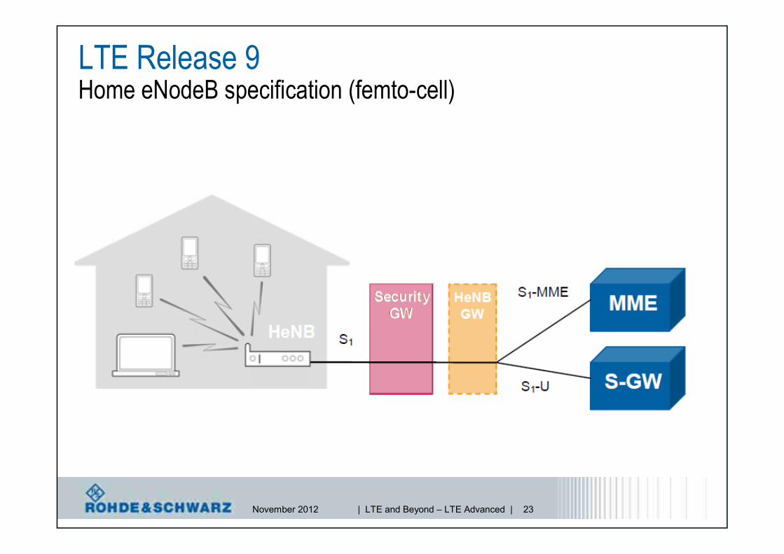
LTE Release 9Home eNodeB specification (femto-cell)

November 2012 | LTE and Beyond – LTE Advanced | 24
LTE Release 9Home eNodeB specification (femto-cell)
l Prime objectives,l Low power access point to improve indoor coverage and increased data rates,
l Challenge – Think about 1000+ femto-cells switched ON at one pointin time,l Typically associated with uncoordinated and large scale deployment, thus
requiring specific thoughts on interference protection of macro deployments,
l Specification of different base station classes (wide area, local area,home BS), basically providing RF requirements for FDD and TDD,l Transmitter: BS output power, unwanted emissions, frequency error,
intermodulation, protection of E-UTRA and UTRA operation in adjacentchannels,
l Receiver: Sensitivity, dynamic range, in-channel and adjacent channelselectivity, blocking, intermodulation,
November 2012 | LTE and Beyond – LTE Advanced | 25
LTE Release 9
l Information sharingl Evolved Multimedia Broadcast Multicast Services (eMBMS)l Public Warning System
l RFl Beamformingl Multi-Carrier, multi-RAT Base Stationsl Home eNodeB
l Infrastructurel Self Organizing Network (SON)l Positioning

November 2012 | LTE and Beyond – LTE Advanced | 26
l Complexity in network deployment and operation has increasedl Multi-technology environments (LTE, CDMA2000/1xEV-DO, WCDMA/HSPA),l Advanced radio interface features and parameterization,
– Parameters to configure at a base station – 2G: 500, 3G: 1000, LTE: 1500*),– Configure a complete 3G network: 64.000.000 parameters*),
l High number of new network elements due to expected Home eNB roll-out,l Tight spectrum usage,
l GOAL?l Three different approaches,
– Self-Configuration (Release 8). Automatic recognition and configuration of a newbase station. The base station will automatically set its basic parameters, identify itsneighbors and establish a relation to them.
– Self-Optimization. Continuous optimization and fine tuning of network (i.e. adjustingneighbor cell lists and handover parameter); measurement of terminals and basestations are evaluated,
– Self-Healing. Algorithms to detect and correct faults automatically, i.e. cell outage.
LTE Release 9Self–Organizing Networks (SON)
*) Source Nokia Siemens Networks
Decrease CAPEX & OPEX!

November 2012 | LTE and Beyond – LTE Advanced | 27
LTE Release 9
l Information sharingl Evolved Multimedia Broadcast Multicast Services (eMBMS)l Public Warming System
l RFl Beamformingl Multi-Carrier, multi-RAT Base Stationsl Home eNodeB
l Infrastructurel Self Organizing Network (SON)l Positioning
November 2012 | LTE and Beyond – LTE Advanced | 28
LTE positioningPhysical layer aspects
l Positioning using a method based on time measurementsrequires that the timing of at least three geographicallydispersed base stations is measured.l In practice it is favorable to be able to measure, say, five base
stations, since the three strongest sites don’t necessarily provide agood geometry for position determination.
l 3GPP concluded that cell-specific reference signals (CS-RS)are not sufficient to provide required accuracy ofpositioning.l Hence, new positioning reference signals (PRS) were defined.

November 2012 | LTE and Beyond – LTE Advanced | 29
LTE positioningPositioning Reference Signals (PRS)
l Introduction of positioning reference signals (PRS) for antennaport 6.
l PRS is a pseudo-random QPSK sequence similar to CS-RS.l Diagonal pattern with time varying frequency shift.l PRS mapped around CS-RS (to avoid collisions).
0l 6l 0l 6l
6R
6R
6R
6R6R
6R
6R
6R
6R
6R
6R
6R
6R
6R
0l 6l 0l 6l
6R
6R
6R
6R6R
6R
6R
6R
6R
6R
6R
6R
6R
6R
6R
6R
even- numbered slots odd- numbered slots
Antenna port 6
even - numbered slots odd- numbered slots
Antenna port 6

November 2012 | LTE and Beyond – LTE Advanced | 30
LTE positioningPositioning Reference Signals (PRS)
0l 6l 0l 6l
Four
PBC
Han
tenn
apo
rts
6R
6R
6R
6R6R
6R
6R
6R
6R
6R
6R
6R
6R
6R
0l 6l 0l 6l
One
and
two
PBC
Han
tenn
apo
rts
6R
6R
6R
6R6R
6R
6R
6R
6R
6R
6R
6R
6R
6R
6R
6R
PRS mapped around CS-RS (to avoid collisions).
November 2012 | LTE and Beyond – LTE Advanced | 31
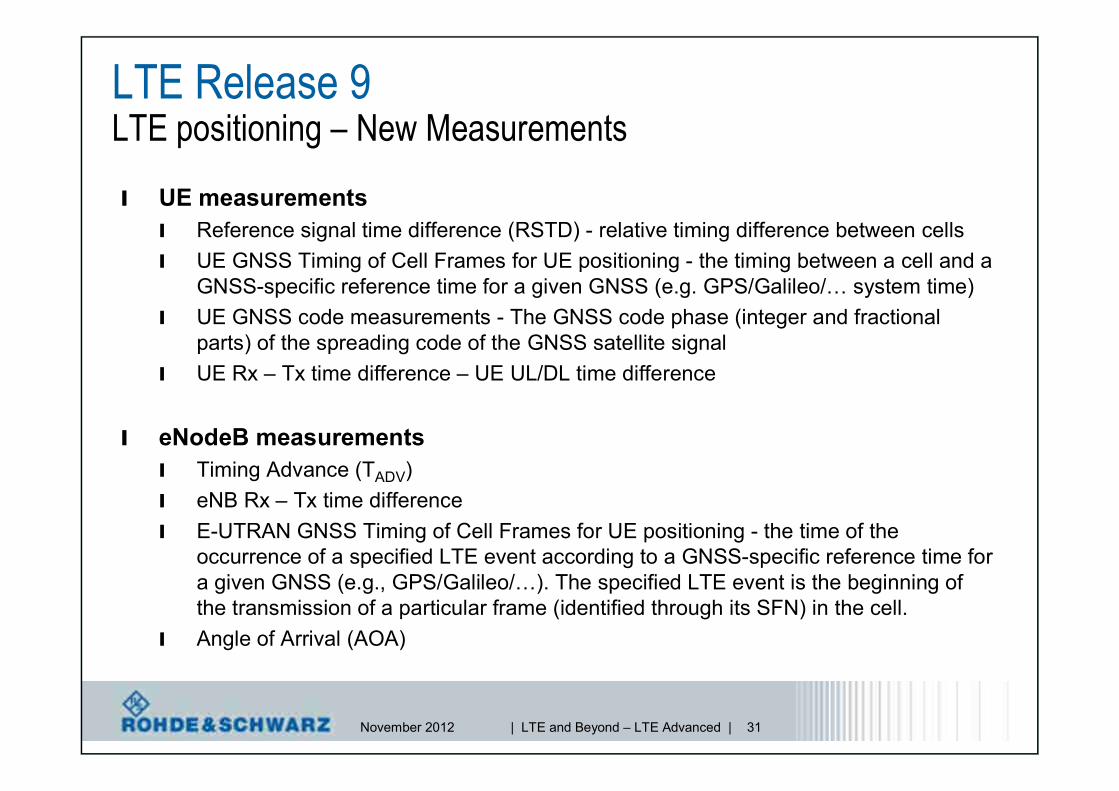
LTE Release 9LTE positioning – New Measurements
l UE measurementsl Reference signal time difference (RSTD) - relative timing difference between cellsl UE GNSS Timing of Cell Frames for UE positioning - the timing between a cell and a
GNSS-specific reference time for a given GNSS (e.g. GPS/Galileo/… system time)l UE GNSS code measurements - The GNSS code phase (integer and fractional
parts) of the spreading code of the GNSS satellite signall UE Rx – Tx time difference – UE UL/DL time difference
l eNodeB measurementsl Timing Advance (TADV)l eNB Rx – Tx time differencel E-UTRAN GNSS Timing of Cell Frames for UE positioning - the time of the
occurrence of a specified LTE event according to a GNSS-specific reference time fora given GNSS (e.g., GPS/Galileo/…). The specified LTE event is the beginning ofthe transmission of a particular frame (identified through its SFN) in the cell.
l Angle of Arrival (AOA)

November 2012 | LTE and Beyond – LTE Advanced | 32
LTE Release 8FDD / TDD
DL UL
DL UL
The LTE evolutionRel-10
Relaying
SONenhancements
CarrierAggregation
MIMO 8x8 MIMO 4x4EnhancedSC-FDMA
eICIC
Rel-9
CoMP
In-deviceco-existenceDiverse Data
Application
Relaying
eICICenhancements
eMBMSenhancements
Rel-11
eMBMS
PositioningDual Layer
Beamforming
Multi carrier /Multi-RAT
Base Stations
Home eNodeB
Self OrganizingNetworks
Public WarningSystem
Public WarningSystem
eMBMS
Public WarningSystem
Positioning
eMBMS
Public WarningSystem
Dual LayerBeamformingPositioning
eMBMS
Public WarningSystem
Home eNodeBDual LayerBeamformingPositioning
eMBMS
Public WarningSystem
Multi carrier /Multi-RAT
Base Stations
Home eNodeBDual LayerBeamformingPositioning
eMBMS
Public WarningSystem Self Organizing
Networks
Multi carrier /Multi-RAT
Base Stations
Home eNodeBDual LayerBeamformingPositioning
eMBMS
Public WarningSystem

November 2012 | LTE and Beyond – LTE Advanced | 33
IMT-Advanced
LTERelease 8
LTE-AdvancedRelease 10
Transmission bandwidth (MHz) ≥≥ 40 ≤≤ 20 ≤≤ 100
Peak data rate (DL/UL) (Mbps) - 100/50 1000/500
Peak spectralefficiency (bps/Hz)
DL (4x4/8x8)15
15 16/30
UL (2x2/4x4)6.75 3.75 8.1/16.1
Latency (ms)
User plane<10 4.9 4.9
Control plane<100 50 50
IMT-Advanced RequirementsSpectral efficiency

November 2012 | LTE and Beyond – LTE Advanced | 34
The LTEvolution to 4GLTE Rel-8 LTE Rel-9 LTE Rel-10
= LTE-A
2009/10/11 2012 2013+ Commercial operation
MIMO (DL) 8x8MIMO (UL) 4x4
EnhancedSC-FDMA
PUCCHPUCCH PUSCHPUSCHf [MHz]
Carrier Aggregation
X2 X2
EnhancedICIC
Relaying*
*Moved to Rel11

November 2012 | LTE and Beyond – LTE Advanced | 35
LTE Release 10
l LTE-Advanced features as of 3GPP Rel-10.l Downlink
– Carrier aggregation.– MIMO enhancements in Downlink.– Enhanced Inter-Cell Interference Cancellation (eICIC).
l Uplink– Enhanced SC-FDMA.– MIMO in Uplink.

November 2012 | LTE and Beyond – LTE Advanced | 36
l Two or more component carriers are aggregated in LTE-Advancedin order to support wider bandwidths up to 100 MHz.l Support for contiguous and non-
contiguous component carrieraggregation (intra-band) andinter-band carrier aggregation.
l Different bandwidths percomponent carrier (CC) are possible.
l Each CC limited to a max. of 110 RBusing the 3GPP Rel-8 numerology(max. 5 carriers, 20 MHz each).
l Motivation.l Higher peak data rates to meet
IMT-Advanced requirements.l NW operators: spectrum aggregation, enabling Heterogonous Networks.
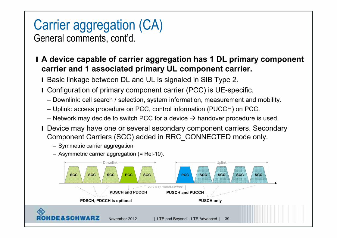
Carrier aggregation (CA)General comments
Frequency band A Frequency band B
Frequency band A Frequency band B
Frequency band A Frequency band B
Intra-band contiguous
Intra-band non-contiguous
Inter-band
ComponentCarrier (CC)
2012 © by Rohde&Schwarz
Intra-band contiguous
Intra-band non-contiguous

November 2012 | LTE and Beyond – LTE Advanced | 37
Carrier aggregation (CA)Specification work (RAN4)
ı There are twocarrier aggregationwork items on LTEin TDD Mode,which are relevantfor intra-bandcarrier aggregationonly

November 2012 | LTE and Beyond – LTE Advanced | 38
Carrier aggregation (CA)Specification work (RAN4)
ı For LTE using FDDmode there is a highinterest in aggregatingfrequency bandsaround 700 MHz and 2GHz Driven by US market
requirements
One single workitem on two uplinkcarrier frequencies
November 2012 | LTE and Beyond – LTE Advanced | 39
Carrier aggregation (CA)General comments, cont’d.
l A device capable of carrier aggregation has 1 DL primary componentcarrier and 1 associated primary UL component carrier.l Basic linkage between DL and UL is signaled in SIB Type 2.l Configuration of primary component carrier (PCC) is UE-specific.
– Downlink: cell search / selection, system information, measurement and mobility.– Uplink: access procedure on PCC, control information (PUCCH) on PCC.– Network may decide to switch PCC for a device handover procedure is used.
l Device may have one or several secondary component carriers. SecondaryComponent Carriers (SCC) added in RRC_CONNECTED mode only.
– Symmetric carrier aggregation.– Asymmetric carrier aggregation (= Rel-10).
SCC PCC PCC SCC
Downlink Uplink
SCC SCC SCCSCCSCCSCC
PDSCH, PDCCH is optional
PDSCH and PDCCH
PUSCH only
PUSCH and PUCCH2012 © by Rohde&Schwarz
November 2012 | LTE and Beyond – LTE Advanced | 40
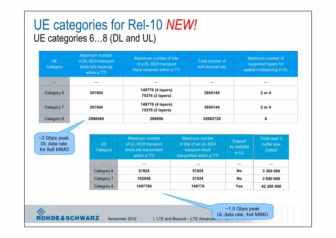
UE categories for Rel-10 NEW!UE categories 6…8 (DL and UL)
UECategory
Maximum numberof DL-SCH transportblock bits received
within a TTI
Maximum number of bitsof a DL-SCH transport
block received within a TTI
Total number ofsoft channel bits
Maximum number ofsupported layers for
spatial multiplexing in DL
… … … … …
Category 6 301504149776 (4 layers)75376 (2 layers)
3654144 2 or 4
Category 7 301504149776 (4 layers)75376 (2 layers)
3654144 2 or 4
Category 8 2998560 299856 35982720 8
~3 Gbps peakDL data ratefor 8x8 MIMO
UECategory
Maximum numberof UL-SCH transportblock bits transmitted
within a TTI
Maximum numberof bits of an UL-SCH
transport blocktransmitted within a TTI
Supportfor 64QAM
in UL
… … … …
Category 6 51024 51024 No
Category 7 102048 51024 No
Category 8 1497760 149776 Yes
Total layer 2buffer size
[bytes]
…
3 300 000
3 800 000
42 200 000
~1.5 Gbps peakUL data rate, 4x4 MIMO

November 2012 | LTE and Beyond – LTE Advanced | 41
Carrier aggregation (CA)Common or separate PDCCH per CC?
No cross-carrierScheduling
(Rel-8)
Time
Freq
uenc
y
PDC
CH
PDC
CH
PDC
CH PDSCH
PDSCH
PDSCH
up to 3 (4) symbolsper subframe
PDC
CH
Cross-carrierscheduling\
(Rel 10)
1 subframe = 1 ms
PDC
CH
PDC
CH
1 slot = 0.5 ms
PDSCH
PDSCH
PDSCH
l No cross-carrier scheduling.l PDCCH on a component carrier assigns
PDSCH resources on the same componentcarrier (and PUSCH resources on a singlelinked UL component carrier).
l Reuse of Rel-8 PDCCH structure (samecoding, same CCE-based resource mapping)and DCI formats.
l Cross-carrier scheduling.l PDCCH on a component carrier can assign
PDSCH or PUSCH resources in one ofmultiple component carriers using the carrierindicator field.
l Rel-8 DCI formats extended with 3 bit carrierindicator field.
l Reusing Rel-8 PDCCH structure (samecoding, same CCE-based resourcemapping).
PCC

November 2012 | LTE and Beyond – LTE Advanced | 42
Carrier aggregation (CA)Cross-carrier scheduling
l Main motivation for cross carrier scheduling: Interferencemanagement for HetNet (eICIC); load balancing.
l Cross carrier scheduling is optional to a UE.l Activated by RRC signaling, if not activated no CFI is present.l Component carriers are numbered, Primary Component Carrier (PCC)
is always cell index 0.l Scheduling on a component carrier is only possible from ONE
component, independent if cross-carrier scheduling is ON or OFF:
l If cross carrier-scheduling active, UE needs to be informed aboutPDSCH start on component carrier RRC signaling.
PDCCH
PDSCH
ComponentCarrier #1
ComponentCarrier #2
ComponentCarrier #5
…not possible,transmissioncan only bescheduled byone CC
PDCCHPDCCH
PDSCH startsignaled by RRC
PCFICH

November 2012 | LTE and Beyond – LTE Advanced | 43
Carrier aggregation (CA)Enhanced uplink feedback mechanism NEW!l Due to carrier aggregation new PUCCH format’s needed to
convey large number of ACK/NACK bits: PUCCH format 3 and1b with channel selection.
l PUCCH format 3.l Not a Zadoff-Chu seq. anymore,
more like PUSCH transmissionusing QPSK.
l Orthogonal Cover Codes (OCC)applied to transmit moreACK/NACK information.– FDD: 10 bits.– TDD: 20 bits.

November 2012 | LTE and Beyond – LTE Advanced | 44
LTE Release 10
l LTE-Advanced features as of 3GPP Rel-10.l Downlink
– Carrier aggregation.– MIMO enhancements in Downlink.– Enhanced Inter-Cell Interference Cancellation (eICIC).
l Uplink– Enhanced SC-FDMA.– MIMO in Uplink.
November 2012 | LTE and Beyond – LTE Advanced | 45
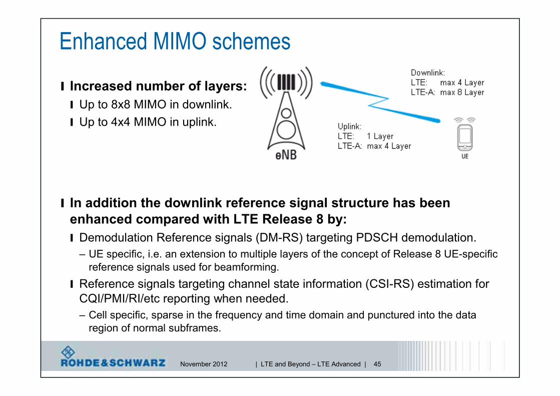
Enhanced MIMO schemesl Increased number of layers:l Up to 8x8 MIMO in downlink.l Up to 4x4 MIMO in uplink.
l In addition the downlink reference signal structure has beenenhanced compared with LTE Release 8 by:l Demodulation Reference signals (DM-RS) targeting PDSCH demodulation.
– UE specific, i.e. an extension to multiple layers of the concept of Release 8 UE-specificreference signals used for beamforming.
l Reference signals targeting channel state information (CSI-RS) estimation forCQI/PMI/RI/etc reporting when needed.– Cell specific, sparse in the frequency and time domain and punctured into the data
region of normal subframes.
November 2012 | LTE and Beyond – LTE Advanced | 46
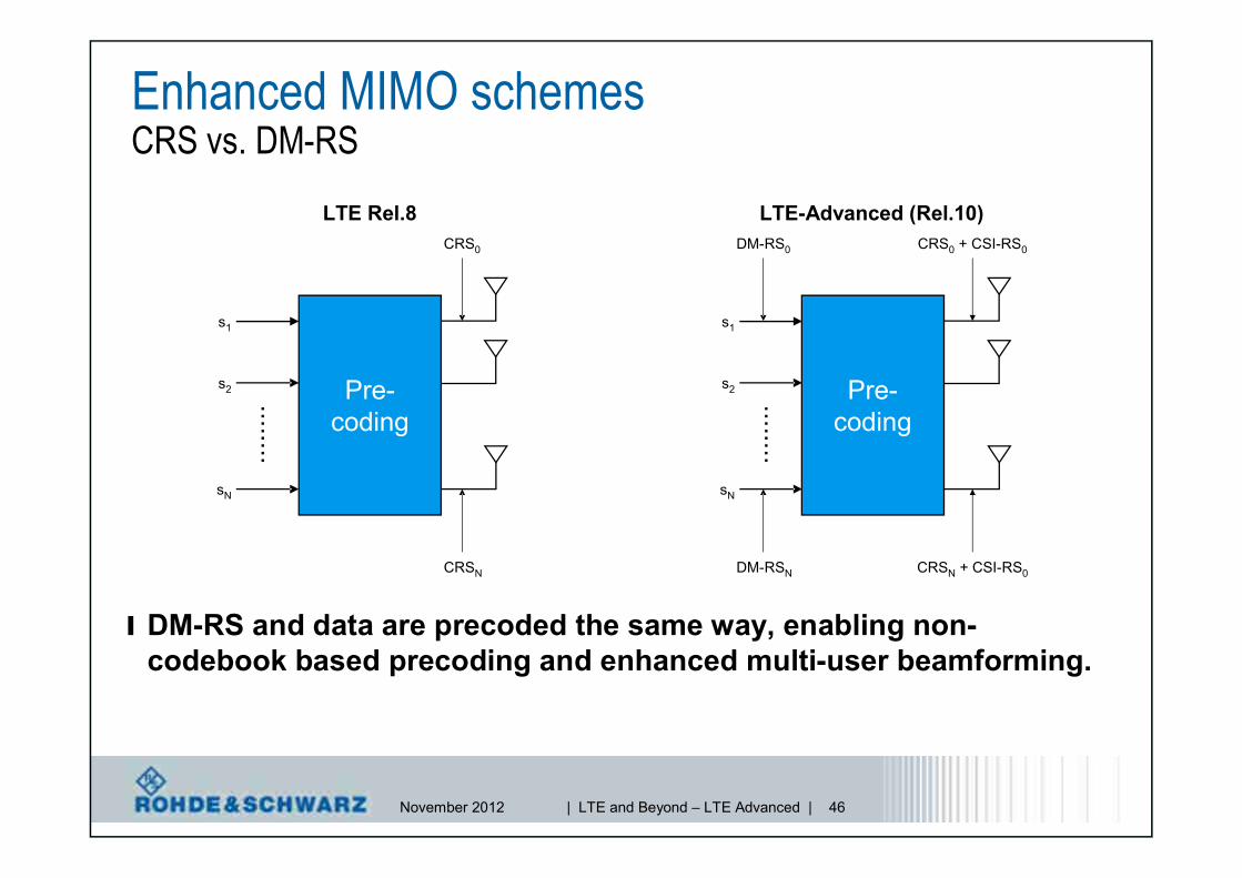
Enhanced MIMO schemesCRS vs. DM-RS
l DM-RS and data are precoded the same way, enabling non-codebook based precoding and enhanced multi-user beamforming.
LTE Rel.8 LTE-Advanced (Rel.10)
s1
s2
sN
........
Pre-coding
s1
s2
sN
........
Pre-coding
CRSN
CRS0
DM-RSN
DM-RS0
CRSN + CSI-RS0
CRS0 + CSI-RS0
November 2012 | LTE and Beyond – LTE Advanced | 47
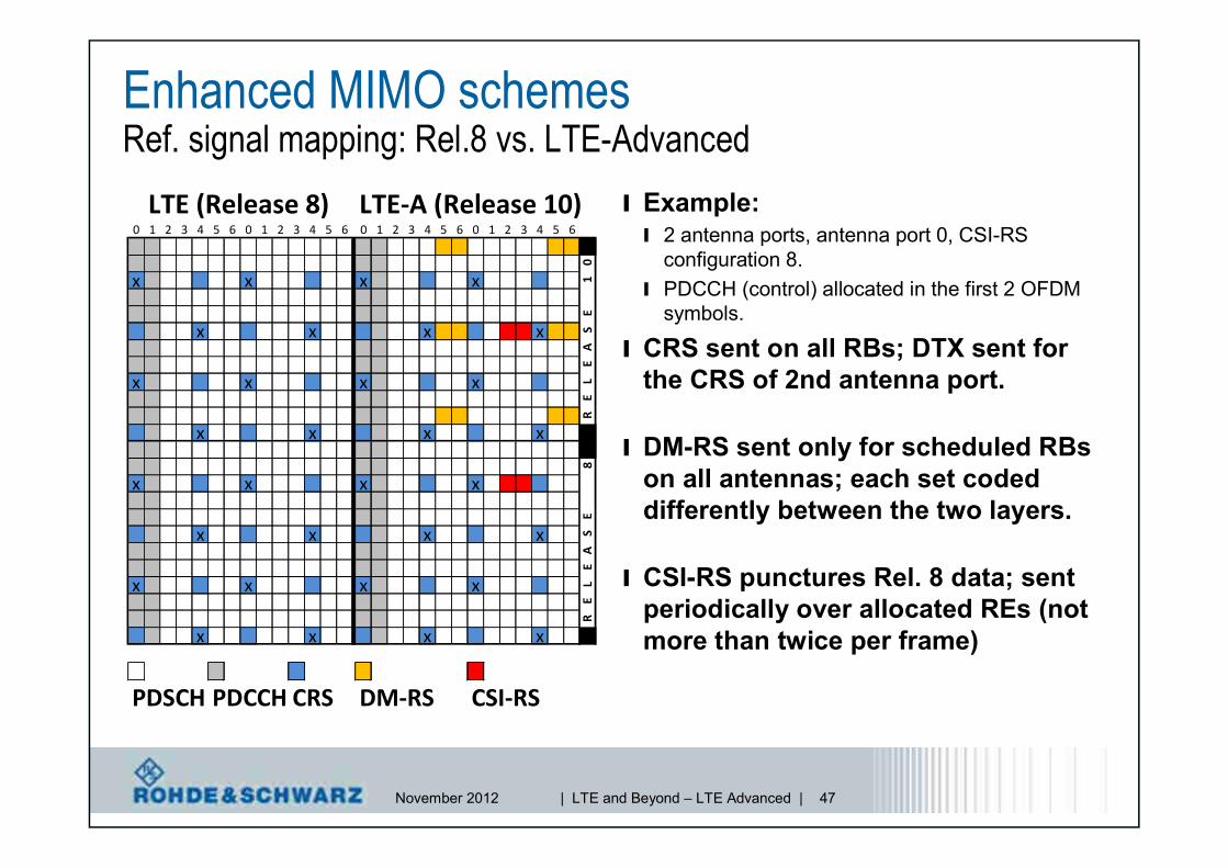
Enhanced MIMO schemesRef. signal mapping: Rel.8 vs. LTE-Advanced
l Example:l 2 antenna ports, antenna port 0, CSI-RS
configuration 8.l PDCCH (control) allocated in the first 2 OFDM
symbols.
l CRS sent on all RBs; DTX sent forthe CRS of 2nd antenna port.
l DM-RS sent only for scheduled RBson all antennas; each set codeddifferently between the two layers.
l CSI-RS punctures Rel. 8 data; sentperiodically over allocated REs (notmore than twice per frame)
LTE (Release 8) LTE-A (Release 10)0 1 2 3 4 5 6 0 1 2 3 4 5 6 0 1 2 3 4 5 6 0 1 2 3 4 5 6
0
x x x x 1E
x x x x SA
E
x x x x LE
R
x x x x
8
x x x x
E
x x x x SA
Ex x x x L
ER
x x x x
PDSCH PDCCH CRS DM-RS CSI-RS

November 2012 | LTE and Beyond – LTE Advanced | 48
Downlink MIMO extension up to 8x8l Max number of transport
blocks: 2l Number of MCS fields.l One for each transport block.
l ACK/NACK feedback.l 1 bit per transport block for
evaluation as a baseline.
l Closed-loop pre-codingsupported.l Rely on pre-coded dedicated
demodulation RS (DM-RS).
l Conclusion on the codeword-to-layer mapping:l DL spatial multiplexing of up to 8 layers
is considered for LTE-Advanced.l Up to 4 layers, reuse LTE CW-to-layer
mapping.l Above 4 layers mapping – see table.

November 2012 | LTE and Beyond – LTE Advanced | 49
Enhanced MIMO schemesScheduling of Transmission Mode 9 (TM9)
l NEW DCI format 2C with 3GPP Rel-10.l Used to schedule transmission mode 9 (TM9), which is spatial multiplexing with DM-
RS support of up to 8 layers (multi-layer transmission).– DM-RS scrambling and number of layers are jointly signaled in a 3-bit field.
l DCI format 2C.– Carrier indicator [3 bit]
– Resource allocation header [1 bit]– Resource Allocation Type 0 and 1
– TPC command for PUCCH [2 bit]
– Downlink Assignment Index1) [2 bit]
– HARQ process number[3 bit (FDD), 4 bit (TDD)]
– Antenna ports, scrambling identifyand # of layers; see table [3 bit]
– SRS request1) [0-1 bit]
– MCS [5 bits], new data indicator [1 bit], RV [2 bits] for each of the two transport blocks
One Codeword:Codeword 0 enabled,Codeword 1 disabled
Two Codewords:Codeword 0 enabled,Codeword 1 enabled
Value Message Value Message
0 1 layer, port 7, nSCID=0 0 2 layers, ports 7-8, nSCID=0
1 1 layer, port 7, nSCID=1 1 2 layers, ports 7-8, nSCID=1
2 1 layer, port 8, nSCID=0 2 3 layers, ports 7-9
3 1 layer, port 8, nSCID=1 3 4 layers, ports 7-10
4 2 layers, ports 7-8 4 5 layers, ports 7-11
5 3 layers, ports 7-9 5 6 layers, ports 7-12
6 4 layers, ports 7-10 6 7 layers, ports 7-13
7 Reserved 7 8 layers, ports 7-14
1) TDD only

November 2012 | LTE and Beyond – LTE Advanced | 50
Release 8 DL MIMO Scheme
Enhanced MIMO schemes
Release 10 MIMO Scheme

November 2012 | LTE and Beyond – LTE Advanced | 51
LTE Release 10
l LTE-Advanced features as of 3GPP Rel-10.l Downlink
– Carrier aggregation.– MIMO enhancements in Downlink.– Enhanced Inter-Cell Interference Cancellation (eICIC).
l Uplink– Enhanced SC-FDMA.– MIMO in Uplink.

November 2012 | LTE and Beyond – LTE Advanced | 52
enhanced InterCell InterferenceCoordinationHeterogeneous Networksl LTE Rel8 allows exchange of load balancing information over X2
interface, i.e. ICIC in frequency domain is possible.– However control channels present on all carrier frequencies.
X2 interface
Inter cell interference

November 2012 | LTE and Beyond – LTE Advanced | 53
enhanced InterCell InterferenceCoordinationHeterogeneous Networksl Within Heterogeneous Network (HetNet) deployments, intercell interference
becomes even more critical due to different base station transmit powersused in different cell layers (e.g. macro and pico cells).
l LTE Rel10 (LTE-A) extends ICIC to the time domain by applying so-calledABS (Almost Blank Subframes).
– Transmission of PSS/SSS/PBCH/Paging maintained with associated PDCCH for SIB1 and Paging, allrequired for legacy Rel 8 UEs.
l Additionally allows UEs to stay connected with cells with low SINR, which requires toimplement interference cancellation techniques at the UE. Effectively increases range ofpico cells.
X2 X2Pico
Macro
time
Cell layer

November 2012 | LTE and Beyond – LTE Advanced | 54
LTE Release 10
l LTE-Advanced features as of 3GPP Rel-10.l Downlink
– Carrier aggregation.– MIMO enhancements in Downlink.– Enhanced Inter-Cell Interference Cancellation (eICIC).
l Uplink– Enhanced SC-FDMA.– MIMO in Uplink.

November 2012 | LTE and Beyond – LTE Advanced | 55
What’s behind “Enhanced SC-FDMA”?l On top of 3GPP Release 8 principles: Allow simultaneous
transmission of PUSCH and PUCCH; dynamic switch ispossible,l Improve uplink spectral efficiency as required by IMT-Advanced,
– 7%...23% improvement taking no impairments (intermodulation, errors inchannel estimation or power control) into account, still 2%...13% doing so,
l Avoid new mechanism of multiplexing control information and data,while utilizing for example:– Higher-order MIMO (up to 8x8) in the downlink,– Asymmetric carrier aggregation (e.g. 2 DL, 1 UL),
l More efficient resource (bandwidth) utilization,– Worst case scenario shows that up to 66% of PUSCH bandwidth might be
used for uplink control information (UCI),l Reliable control information, control information to non-serving cells,
l Frequency-selective transmission/scheduling (multi-cluster),l Referred to as clustered DFT-spread-OFDM, instead of localized SC-
FDMA.

November 2012 | LTE and Beyond – LTE Advanced | 56
f [MHz]
Enhanced SC-FDMASimultaneous PUSCH-PUCCH transmission, multi-cluster transmissionl Remember, only one UL carrier in 3GPP Release 10;
scenarios:l Feature support is indicated by PhyLayerParameters-v1020 IE*).
PUCCHPUCCH PUSCHPUSCH
PUCCH andallocated PUSCH
PUCCH and fullyallocated PUSCH
PUCCH and partiallyallocated PUSCH
partiallyallocated PUSCH
f [MHz]
f [MHz] f [MHz]
*) see 3GPP TS 36.331 RRC Protocol Specification
Release 8
Release 10

November 2012 | LTE and Beyond – LTE Advanced | 57
Enhanced SC-FDMAResource Allocation types in the uplink
l Uplink Resource Allocation Type 0.l Contiguous allocation as today in 3GPP Release 8.
l Uplink Resource Allocation Type 1 (Release 10).l UL bandwidth is divided into two clusters of Resource Blocks (RB).l Each set has a number of Resource Block Groups (RBG) of size P.l Combinatorial index r, indicates RBG starting and ending index for both
set of RB (s0, s1-1 | s2, s3-1).
– M = 4, N is bandwidth dependent,
SystemBandwidth
RBGSize (P)
≤10 1
11 – 26 2
27 – 63 3
64 – 110 4
1
0
Mi
i
N sr
M i
1/ULRB PNN
1
0
Mi is
11 ,i i is N s s

November 2012 | LTE and Beyond – LTE Advanced | 58
l Example: LTE 10 MHz (50 RB), P = 3 leads to 17 RBG.l Combinatorial index r indicates RBG starting indices for RB set #1 (s0,
s1-1, defining cluster #1) and RB set #2 (s2, s3-1, defining cluster #2).l Range for s0, s1, s2, s3 for 10 MHz (50 RB): 1 to 18 (see previous slide).l Applied rule: s0 < s1 < s2 < s3 (see previous slide).l Example: s0=2, s1=9, s2=10, s3=11:
Enhanced SC-FDMAMulti-cluster allocation, Uplink Resource Allocation Type 1
“START”(s0)
“END”(s1-1)
“START”(s2) “END”
(s3-1)
Cluster #1 Cluster #2
RBG#11 RBG#13 RBG#15RBG#1 RBG#3 RBG#5 RBG#7 RBG#9
RBG#0 RBG#8 RBG#12 RBG#14 RBG#16RBG#10RBG#2 RBG#4 RBG#6

November 2012 | LTE and Beyond – LTE Advanced | 59
Enhanced SC-FDMAApplication example – intermodulation test
l LTE release 8
l PUSCH and PUCCH are not present at the same time
Rel-8

November 2012 | LTE and Beyond – LTE Advanced | 60
Enhanced SC-FDMAApplication example – intermodulation test
l LTE release 10
simultaneousPUSCH/PUCCH
l Intermodulation occurs!
Rel-10

November 2012 | LTE and Beyond – LTE Advanced | 61
LTE Release 10
l LTE-Advanced features as of 3GPP Rel-10.l Downlink
– Carrier aggregation.– MIMO enhancements in Downlink.– Enhanced Inter-Cell Interference Cancellation (eICIC).
l Uplink– Enhanced SC-FDMA.– MIMO in Uplink.

November 2012 | LTE and Beyond – LTE Advanced | 62
Uplink MIMOExtension up to 4x4l Rel-8 LTE.l UEs must have 2 antennas for reception.l But only 1 amplifier for transmission is available (costs/complexity).l UL MIMO only as antenna switching mode (switched diversity).
l 4x4 UL SU-MIMO is needed to fulfill peak data raterequirement of 15 bps/Hz.
l Specified schemes are very similar to DL MIMO modes.l UL spatial multiplexing of up to 4 layersl SRS enables link and SU-MIMO adaptation
l Note that 4x4 MIMO is not fully completed in Release 10, but4Tx in Uplink was postponed to 3GPP Release 11
November 2012 | LTE and Beyond – LTE Advanced | 63
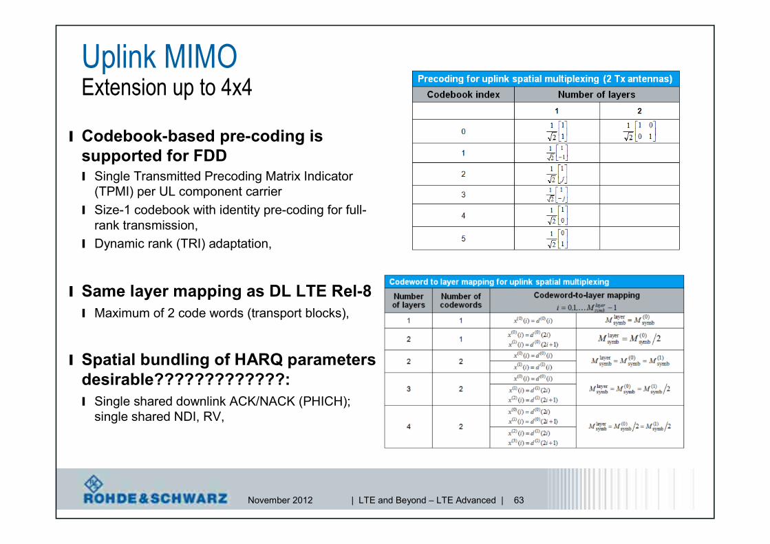
Uplink MIMOExtension up to 4x4
l Codebook-based pre-coding issupported for FDDl Single Transmitted Precoding Matrix Indicator
(TPMI) per UL component carrierl Size-1 codebook with identity pre-coding for full-
rank transmission,l Dynamic rank (TRI) adaptation,
l Same layer mapping as DL LTE Rel-8l Maximum of 2 code words (transport blocks),
l Spatial bundling of HARQ parametersdesirable?????????????:l Single shared downlink ACK/NACK (PHICH);
single shared NDI, RV,

November 2012 | LTE and Beyond – LTE Advanced | 64
UL MIMOScheduling – DCI format 4 NEW!l Carrier indicator [0-3 bit]l Resource Block Assignment:l number of bits depends on system bandwidth and
corresponding RBG size
l TPC command for PUSCH [2 bit]l Cyclic shift for DM RS and OCC index [2
bit]l UL index [2 bit]l TDD only for UL-DL configuration 0
l Downlink Assignment Index [2 bit]l TDD only, UL-DL configuration 1-6
l CSI request [1 or 2 bit]l 2 bit for cells with more than two cells in the DL (carrier
aggregation)
l SRS request [2 bit]l Resource Allocation Type [1 bit]
l Transport Block 1l MCS, RV [5 bit]
l New data indicator [1 bit]
l Transport Block 2l MCS, RV [5 bit]
l New data indicator [1 bit]
l Precoding:l Transmitted Precoding Matrix Index
(TMPI) [3/6 bits for 2/4 antennaports]
l See table for two antenna portexample

November 2012 | LTE and Beyond – LTE Advanced | 65
LTE-AdvancedSummary
l LTE-Advanced features deliver different performance gainsand will have different impacts on the system complexity /cost.
l LTE Release 8 / LTE-Advanced will be the innovationplatform for the cellular industry for the next decade.
Peak Rate Capacity Cell EdgePerformance Coverage Complexity
Carrier Aggregation - - Medium
Enhanced SC-FDMA - - Low
eICIC - Medium
Enhanced DL MIMO - High
Enhanced UL MIMO - High
November 2012 | LTE and Beyond – LTE Advanced | 66
LTE-AdvancedSummary
l LTE-Advanced (Rel.10)l Goal: higher data rates, increase spectral efficiency.l Achieved by: carrier (or spectrum) aggregation, enhanced MIMO.
l Design implication.l Increased receiver complexity driven by # of carrier and antennas.l Cross-carrier scheduling, new reference signal structure.l Main challenges on RF front-end: wideband PA’s. tunable antennas.
l LTE = “Long Term Employment”.l More features to come with Rel.11 and Rel.12: UTDOA, CoMP, feICIC,
Machine Type Communication, Device-to-Device (D2D)communication.
November 2012 | LTE and Beyond – LTE Advanced | 67
LTE-Advanced Feature ReviewR&S Opinion
l Carrier aggregation is obviously one of the priority features withinLTE-Advancedl High number of specific band combinations now worked on in 3GPPl Not only increasing peak data rate, but also adding flexibility in resource
allocationl However implementation effort @ UE side to be considered even with
restriction to 1 Tx UL onlyl MIMO schemes
l More than 4x2 (FDD) and 8x2 (TDD) in DL and 2x2 in UL not visible short oreven mid term when it comes to commercial equipment (specifically UE)
l However 8x8 MIMO implemented in demo systems (infrastructuremanufacturers and operators).
l eICIC and Enhanced UL scheme less impact on R&S portfolio,however also important subjects to be implemented
l Relaying depends on individual operator strategies

November 2012 | LTE and Beyond – LTE Advanced | 68
Signaling Conformance
Radio networkanalyzers incl.ROMES Drive
Test Tools
RF Conformance
R&S®CMW500including 3GPP
conformance tests
R&S®TS8980RF TestSystem
&RRM TestSystem
R&S®CMW500
Testing of- Protocol Layers- Operator Scenarios- E2E Application-Max. Throughput- IP4/6- MIMO- Handover
Signal Generator / Fading Simulator
Signal Analyzer/ Power Meter
R&S®FSW/FSQ/FSV(R)
R&S®SMU200A /R&S®AMU200A
One box Mobile Radio Tester for Calibration,Verification and Functional Test
R&S®CMW500R&S®FSH
TS8980FTA+ out-of-band andTV interferer tests
Installation andMaintenance
TD-LTE and LTE FDD,RF and protocol test
cases validatedby GCF
TD-LTE,LTE FDD, GSM,
WCDMA/HSPA(+),CDMA2k and WLAN
in one box!
R&S®NRP
R&S LTE Portfolio for chipset, component,device and base station testing
RF Development Protocol Stack Field Conformanceand Production and IOT Testing Testing
LTE functionalitysince 2006
R&S®SMBV100

November 2012 | LTE and Beyond – LTE Advanced | 69
NW-basedPositioning(UTDOA)
Rel-11
Further eMBMSenhancements
CAenhancements
Diverse DataApplication
In-DeviceCoexistence
RelayingFurthereICIC CoMP
The LTE evolution beyond Release 10Rel-10
Rel-9
LTE Release 8FDD / TDD
RelayingSON
enhancements
CarrierAggregation
DL MIMO8x8
UL MIMO4x4
EnhancedSC-FDMA
eICIC
eMBMSenhancements
Positioning
Dual LayerBeamforming
Multi carrier /Multi-RAT
Base Stations
HomeeNodeB
Self OrganizingNetworks
Public WarningSystem (PWS)
November 2012 | LTE and Beyond – LTE Advanced | 70
Read more…1MA-169 Application Note 1MA-166 Application Note

November 2012 | LTE and Beyond – LTE Advanced | 71
Thank you!