ricoh aficio 2852_3352 service manual
DESCRIPTION
Service Manual for Ricoh Aficio 2852/3352TRANSCRIPT

Model OR-C1 Machine Code:
D120/D121/D122/D139/D140/D141
Field Service Manual
July, 2011 Subject to change

Safety, Conventions, Trademarks
Safety
Prevention of Physical Injury
1. Before disassembling or assembling parts of the machine and peripherals, make sure that themachine and peripheral power cords are unplugged.
2. The plug should be near the machine and easily accessible.
3. Note that some components of the machine and the paper tray unit are supplied with electricalvoltage even if the main power switch is turned off.
4. If any adjustment or operation check has to be made with exterior covers off or open while themain switch is turned on, keep hands away from electrified or mechanically driven components.
5. If the [Start] key is pressed before the machine completes the warm-up period (the [Start] key startsblinking red and green ), keep hands away from the mechanical and the electrical components asthe machine starts making copies as soon as the warm-up period is completed.
6. The inside and the metal parts of the fusing unit become extremely hot while the machine isoperating. Be careful to avoid touching those components with your bare hands.
7. To prevent a fire or explosion, keep the machine away from flammable liquids, gases, andaerosols.
Health Safety Conditions
1. Never operate the machine without the ozone filters installed.
2. Always replace the ozone filters with the specified types at the proper intervals.
3. Toner and developer are non-toxic, but if you get either of them in your eyes by accident, it maycause temporary eye discomfort. Try to remove with eye drops or flush with water as first aid. Ifunsuccessful, get medical attention.
Observance of Electrical Safety Standards
1. The machine and its peripherals must be installed and maintained by a customer servicerepresentative who has completed the training course on those models.
Safety and Ecological Notes for Disposal
1. Do not incinerate toner bottles or used toner. Toner dust may ignite suddenly when exposed to anopen flame.
1

2. Dispose of used toner, developer, and organic photoconductors in accordance with localregulations. (These are non-toxic supplies.)
3. Dispose of replaced parts in accordance with local regulations.
4. When keeping used lithium batteries in order to dispose of them later, do not put more than 100batteries per sealed box. Storing larger numbers or not sealing them apart may lead to chemicalreactions and heat build-up.
• The danger of explosion exists if a battery of this type is incorrectly replaced. Replace only with thesame or an equivalent type recommended by the manufacturer. Discard used batteries inaccordance with the manufacturer’s instructions.
Handling Toner
• Work carefully when removing paper jams or replacing toner bottles or cartridges to avoid spillingtoner on clothing or the hands.
• If toner is inhaled, immediately gargle with large amounts of cold water and move to a wellventilated location. If there are signs of irritation or other problems, seek medical attention.
• If toner gets on the skin, wash immediately with soap and cold running water.
• If toner gets into the eyes, flush the eyes with cold running water or eye wash. If there are signs ofirritation or other problems, seek medical attention.
• If toner is swallowed, drink a large amount of cold water to dilute the ingested toner. If there aresigns of any problem, seek medical attention.
• If toner spills on clothing, wash the affected area immediately with soap and cold water. Never usehot water! Hot water can cause toner to set and permanently stain fabric.
• Always store toner and developer supplies such as toner and developer packages, cartridges, andbottles (including used toner and empty bottles and cartridges) out of the reach of children.
• Always store fresh toner supplies or empty bottles or cartridges in a cool, dry location that is notexposed to direct sunlight.
Laser Safety
The Center for Devices and Radiological Health (CDRH) prohibits the repair of laser-based optical unitsin the field. The optical housing unit can only be repaired in a factory or at a location with the requisiteequipment. The laser subsystem is replaceable in the field by a qualified Customer Engineer. The laserchassis is not repairable in the field. Customer engineers are therefore directed to return all chassis andlaser subsystems to the factory or service depot when replacement of the optical subsystem is required.
2

• Use of controls, or adjustment, or performance of procedures other than those specified in thismanual may result in hazardous radiation exposure.
WARNING FOR LASER UNIT
WARNING:
Turn off the main switch before attempting any of the procedures in the Laser Unit section. Laser beamscan seriously damage your eyes.
CAUTION MARKING:
Safety Precautions for This Machine
Before moving the mainframe:
• Disconnect all peripheral units (finisher, LCT, etc.) from the mainframe.
• Pull the slide handles out of the mainframe and use them to lift the mainframe.
Conventions and Trademarks
Conventions
Symbol What it means
CT Core Tech Manual
Screw
Connector
E-ring
3

Symbol What it means
C-ring
Harness clamp
FFC Flat Film Connector
The notations "SEF" and "LEF" describe the direction of paper feed. The arrows indicate the direction ofpaper feed.
In this manual "Horizontal" means the "Main Scan Direction" and "Vertical" means the "Sub ScanDirection" relative to the paper feed direction.
4

Warnings, Cautions, Notes
In this manual, the following important symbols and notations are used.
• A Warning indicates a potentially hazardous situation. Failure to obey a Warning could result indeath or serious injury.
• A Caution indicates a potentially hazardous situation. Failure to obey a Caution could result inminor or moderate injury or damage to the machine or other property.
• Obey these guidelines to avoid problems such as misfeeds, damage to originals, loss of valuabledata and to prevent damage to the machine
• This information provides tips and advice about how to best service the machine.
Trademarks
• Microsoft®, Windows®, and MS-DOS® are registered trademarks of Microsoft Corporation in theUnited States and /or other countries.
• PostScript® is a registered trademark of Adobe Systems, Incorporated.
• PCL® is a registered trademark of Hewlett-Packard Company.
• Ethernet® is a registered trademark of Xerox Corporation.
• PowerPC® is a registered trademark of International Business Machines Corporation.
• Other product names used herein are for identification purposes only and may be trademarks oftheir respective companies. We disclaim any and all rights involved with those marks.
5

TABLE OF CONTENTSSafety, Conventions, Trademarks......................................................................................................................1
Safety...............................................................................................................................................................1
Laser Safety.....................................................................................................................................................2
Safety Precautions for This Machine.............................................................................................................3
Conventions and Trademarks........................................................................................................................3
Warnings, Cautions, Notes...........................................................................................................................5
1. Product Information
Specifications....................................................................................................................................................15
Machine Configuration....................................................................................................................................16
System Configuration and Options............................................................................................................16
Guidance for Those Who are Familiar with Predecessor Products..............................................................19
Overview..........................................................................................................................................................20
Mechanical Components............................................................................................................................20
Paper Path....................................................................................................................................................22
Drive Layout..................................................................................................................................................23
2. Installation
Installation Requirements.................................................................................................................................25
Environment..................................................................................................................................................25
Machine Level..............................................................................................................................................25
Minimum Space Requirements...................................................................................................................25
Power Requirements....................................................................................................................................27
Copier Installation............................................................................................................................................28
Power Sockets for Peripherals.....................................................................................................................28
Accessory Check..........................................................................................................................................28
Installation Procedure..................................................................................................................................30
Transporting the Machine...........................................................................................................................43
Paper Feed Unit PB3120 (D579)...................................................................................................................44
Accessory Check..........................................................................................................................................44
Installation Procedure..................................................................................................................................44
Caster Table Type D (D593)...........................................................................................................................49
Component Check.......................................................................................................................................49
Installation Procedure..................................................................................................................................49
Paper Feed Unit PB3130 (D580)...................................................................................................................52
6

Accessory Check..........................................................................................................................................52
Installation Procedure..................................................................................................................................52
LCIT PB3140 (D581).......................................................................................................................................57
Accessory Check..........................................................................................................................................57
Installation Procedure..................................................................................................................................57
ARDF DF3060 (D578)....................................................................................................................................62
Component Check.......................................................................................................................................62
Installation Procedure..................................................................................................................................63
1 Bin Tray BN3090 (D582)...........................................................................................................................66
Component Check.......................................................................................................................................66
Installation Procedure..................................................................................................................................66
Internal Shift Tray SH3050 (D583)................................................................................................................71
Component Check.......................................................................................................................................71
Installation Procedure..................................................................................................................................71
Bridge Unit BU3050 (D584)..........................................................................................................................74
Component List.............................................................................................................................................74
Installation Procedure..................................................................................................................................74
Finisher SR3090 (D588).................................................................................................................................77
Accessory Check..........................................................................................................................................77
Installation Procedure..................................................................................................................................78
Booklet Finisher SR3100 (D589)...................................................................................................................81
Accessory Check..........................................................................................................................................81
Installation Procedure..................................................................................................................................82
Punch Kit PU3000 (B807)..............................................................................................................................86
Component Check.......................................................................................................................................86
Installation....................................................................................................................................................87
Finisher SR3070 (D585).................................................................................................................................94
Accessory Check..........................................................................................................................................94
Installation Procedure..................................................................................................................................95
Internal Finisher Type 3352 (D586)..............................................................................................................98
Component Check.......................................................................................................................................98
Installation Procedure..................................................................................................................................99
Punch Kit PU3020 (D587)...........................................................................................................................105
7

Component Check.....................................................................................................................................105
Installation Procedure................................................................................................................................106
Platen Cover (D597).....................................................................................................................................116
Key Counter Bracket Type H (A674)...........................................................................................................117
Installation Procedure................................................................................................................................117
Optional Counter Interface Unit Type A (B870).........................................................................................119
Installation Procedure................................................................................................................................119
Heaters...........................................................................................................................................................122
Anti-Condensation Heater (Scanner Unit)..............................................................................................122
Tray Heater (Copier).................................................................................................................................124
Tray Heater (Optional Paper Feed Unit).................................................................................................125
Tray Heater (Optional LCT)......................................................................................................................134
Mechanical Counter......................................................................................................................................139
Accessory Check.......................................................................................................................................139
Installation..................................................................................................................................................139
Copy Data Security Unit Type F (B829)......................................................................................................141
Component Check.....................................................................................................................................141
Installation..................................................................................................................................................141
Hard Disk (D594)..........................................................................................................................................144
Accessory Check.......................................................................................................................................144
Installation..................................................................................................................................................144
File Format Converter Type E (D377)..........................................................................................................149
Accessory Check.......................................................................................................................................149
Installation..................................................................................................................................................149
Browser Unit Type E (D430).........................................................................................................................151
Accessories................................................................................................................................................151
Installation..................................................................................................................................................151
VM Card Type N (D594).............................................................................................................................153
Accessories................................................................................................................................................153
Installation..................................................................................................................................................153
USB2.0/SD Slot Type H (D594).................................................................................................................155
Accessory Check.......................................................................................................................................155
Installation Procedure................................................................................................................................155
8

Testing the SD Card/USB Slot.................................................................................................................164
Card Reader Bracket Type C3352 (D593)................................................................................................165
Component Check.....................................................................................................................................165
Installation Procedure................................................................................................................................165
3. Preventive Maintenance
PM Tables.......................................................................................................................................................171
4. Replacement and Adjustment
Beforehand.....................................................................................................................................................173
Special Tools and Lubricants........................................................................................................................174
Special Tools..............................................................................................................................................174
Lubricants...................................................................................................................................................174
General Cautions..........................................................................................................................................175
PCU (Photoconductor Unit)......................................................................................................................175
Transfer Roller Unit....................................................................................................................................175
Scanner Unit..............................................................................................................................................176
Laser Unit....................................................................................................................................................176
Fusing Unit..................................................................................................................................................176
Paper Feed.................................................................................................................................................176
Others.........................................................................................................................................................176
Exterior Covers...............................................................................................................................................178
Front Door..................................................................................................................................................178
Controller Cover........................................................................................................................................179
Left Cover...................................................................................................................................................179
Upper Left Cover.......................................................................................................................................180
Upper Rear Cover.....................................................................................................................................181
Lower Rear Cover......................................................................................................................................181
Right Rear Cover.......................................................................................................................................181
Upper Right Cover....................................................................................................................................182
Operation Panel........................................................................................................................................183
Paper Exit Cover........................................................................................................................................184
Output Tray................................................................................................................................................185
Scanner Unit...................................................................................................................................................187
Exposure Glass..........................................................................................................................................187
9

Original Length Sensors............................................................................................................................187
Scanner Lamp............................................................................................................................................189
Scanner Motor...........................................................................................................................................194
Lens Block Unit...........................................................................................................................................194
SIO Board..................................................................................................................................................196
Front Scanner Wire...................................................................................................................................196
Rear Scanner Wire....................................................................................................................................203
Touch Panel Position Adjustment..............................................................................................................204
Laser Unit........................................................................................................................................................205
Caution Decal Locations...........................................................................................................................205
Laser Unit....................................................................................................................................................205
Polygon Mirror Motor...............................................................................................................................207
LD Unit........................................................................................................................................................208
Laser Synchronization Detector................................................................................................................208
Photoconductor Unit (PCU)...........................................................................................................................210
PCU Removal.............................................................................................................................................210
Pick-off Pawls.............................................................................................................................................211
OPC Drum..................................................................................................................................................211
Charge Roller, Cleaning Roller ...............................................................................................................213
Cleaning Blade..........................................................................................................................................214
Developer..................................................................................................................................................214
After Replacement of PCU Components..................................................................................................219
Transfer Unit...................................................................................................................................................221
Transfer Roller Unit....................................................................................................................................221
Image Density Sensor...............................................................................................................................221
Fusing/Exit.....................................................................................................................................................223
Fusing Unit..................................................................................................................................................223
Thermistors.................................................................................................................................................223
Thermostats................................................................................................................................................224
Hot Roller and Fusing Lamps....................................................................................................................226
Pressure Roller/Cleaning Roller...............................................................................................................228
Paper Exit Sensor/Paper Overflow Sensor............................................................................................229
Paper Feed.....................................................................................................................................................232
10

Paper Feed Unit.........................................................................................................................................232
Separation Roller, Feed Roller.................................................................................................................234
Paper Tray Lift Motors...............................................................................................................................235
Registration Clutch.....................................................................................................................................236
Transport Clutch.........................................................................................................................................236
Paper Feed Clutch.....................................................................................................................................238
Paper Size Sensors....................................................................................................................................239
Registration Sensor....................................................................................................................................240
Vertical Transport, Paper Overflow, Paper End and Paper Feed Sensor.............................................242
Dust Collection Box...................................................................................................................................244
Duplex Unit.....................................................................................................................................................245
Duplex Unit................................................................................................................................................245
Duplex Entrance Sensor............................................................................................................................247
Duplex Exit Sensor....................................................................................................................................249
Duplex Motor/Bypass Motor .................................................................................................................250
By-pass Tray Unit.......................................................................................................................................252
By-pass Paper Length Sensor ..................................................................................................................253
By-Pass Paper Size Sensor.......................................................................................................................254
By-pass Paper End Sensor........................................................................................................................256
By-pass Feed Roller...................................................................................................................................256
By-pass Tray HP Sensor............................................................................................................................257
PCBs and Other Items....................................................................................................................................258
Controller Board........................................................................................................................................258
NVRAM......................................................................................................................................................260
BCU Board.................................................................................................................................................261
Power Pack................................................................................................................................................263
Main Motor................................................................................................................................................263
SDB.............................................................................................................................................................264
PSU.............................................................................................................................................................265
IPU..............................................................................................................................................................266
HDD............................................................................................................................................................267
Copy Adjustments: Printing/Scanning.........................................................................................................271
Printing........................................................................................................................................................271
11

Scanning....................................................................................................................................................275
ADF Image Adjustment.............................................................................................................................277
Touch Screen Calibration.........................................................................................................................278
5. System Maintenance
Service Program Mode.................................................................................................................................281
SP Tables....................................................................................................................................................281
Enabling and Disabling Service Program Mode....................................................................................281
Types of SP Modes....................................................................................................................................281
Remarks......................................................................................................................................................285
Firmware Update...........................................................................................................................................286
Type of Firmware.......................................................................................................................................286
Before You Begin.......................................................................................................................................287
Updating Firmware ..................................................................................................................................288
Updating the LCDC for the Operation Panel..........................................................................................290
Update Procedure for App2Me Provider...............................................................................................291
Browser Unit Update Procedure..............................................................................................................292
Handling Firmware Update Errors...........................................................................................................294
Installing Another Language.........................................................................................................................296
Reboot/System Setting Reset.......................................................................................................................299
Software Reset...........................................................................................................................................299
System Settings and Copy Setting Reset..................................................................................................299
NVRAM Data Upload/Download..............................................................................................................301
Uploading Content of NVRAM to an SD card.......................................................................................301
Downloading an SD Card to NVRAM....................................................................................................302
Address Book Upload/Download..............................................................................................................303
Information List...........................................................................................................................................303
Download..................................................................................................................................................303
Upload.......................................................................................................................................................304
LED and DIP Switches....................................................................................................................................306
LEDs............................................................................................................................................................306
DIP Switches...............................................................................................................................................306
Using the Debug Log.....................................................................................................................................308
Overview....................................................................................................................................................308
12

Switching ON and Setting UP Save Debug Log.....................................................................................308
Retrieving the Debug Log from the HDD.................................................................................................312
Recording Errors Manually.......................................................................................................................313
Debug Log Codes.....................................................................................................................................313
User Tools.......................................................................................................................................................315
UP Mode Initial Screen: User Tools/Counter Display...........................................................................315
System Settings..........................................................................................................................................315
Copier/Document Server Features..........................................................................................................316
Printer, Facsimile, Scanner Settings.........................................................................................................316
Inquiry........................................................................................................................................................316
Counter.......................................................................................................................................................317
6. Troubleshooting
Service Call Conditions.................................................................................................................................319
Self-Diagnostic Mode...................................................................................................................................320
Self-Diagnostic Mode at Power On.........................................................................................................320
Detailed Self-Diagnostic Mode................................................................................................................322
Skewed Image...............................................................................................................................................324
Image Problems.............................................................................................................................................325
Skewed, Trapezoid and Parallelogram Images.....................................................................................325
Checking Images with the Trimming Pattern............................................................................................328
Correcting the Images...............................................................................................................................329
Jam Detection.................................................................................................................................................333
Paper Jam Display.....................................................................................................................................333
Jam Codes and Display Codes................................................................................................................333
Electrical Component Defects.......................................................................................................................344
Sensors.......................................................................................................................................................344
Switches.....................................................................................................................................................347
Blown Fuse Conditions..................................................................................................................................348
7. Energy Saving
Energy Save...................................................................................................................................................349
Energy Saver Modes................................................................................................................................349
Energy Save Effectiveness........................................................................................................................350
Paper Save.....................................................................................................................................................352
13

Effectiveness of Duplex/Combine Function............................................................................................352
INDEX...........................................................................................................................................................355
14

1. Product Information
SpecificationsSee "Appendices" for the following information:
• General Specifications
• Supported Paper Sizes
• Software Accessories
• Optional Equipment
15
1

Machine Configuration
System Configuration and Options
No. Item Comments
1 Main Machine D120/D121/D122/D139/D140/D141
2 Platen Cover (D593)
3 ARDF (D578)
4 Paper Feed Unit (D579) Required for item 5
5 Caster Table (D593)
1. Product Information
16
1

No. Item Comments
6 Paper Feed Unit (D580) Required for item 14, 15
7 LCT (D581) Required for item 14, 15
8 1-Bin Tray (D582)
9 Bridge Unit (D584) Required for item 13, 14, 15
10 Internal Shift Tray (D583)
11 Internal Finisher (D586)
12 USB2.0/SD Slot Type H (D594)
13 500-Sheet Finisher (D585) Requires item 9
14 1000-Sheet Finisher (D588) Requires item 9
Requires item 6 or 7
15 Booklet Finisher (D589) Requires item 9
Requires item 6 or 7
16 Copy Data Security Unit Type F (B829)
17 Fax Unit (D596) See Fax manual
18 Interface Board Controller Options See Note 1
19 SD Card Controller Options See Note 2
20 HDD Unit (D594)
21 Bluetooth Interface Unit Type D (D566)
Note 1:
The following interface boards are available for installation.
• There is only one board slot on the back of the machine. Only one of these options can beinstalled.
These options can be installed at any time.
Interface Board
File Format Converter Type E (D377)
Machine Configuration
17
1

Interface Board
IEEE 1284 Interface Board Type A (B679)
IEEE 802.11a/g Interface Unit Type J (D377)
-or-
IEEE 802.11g Interface Unit Type K (D377)
Gigabit Ethernet Board Type A (G874)
Optional Counter Interface Unit Type A (B870)
Note 2:
The following options are provided on SD cards.
• Two SD card slots are available. If more than two options need to be installed, the applications canbe moved to one SD card with SP5873-1.
These options can be installed at any time.
SD Cards
Browser Unit Type E (D430)
PostScript3 Unit Type 3352 (D595)
IPDS Unit Type 3352 (D595)
VM Card Type N (D594) *1
only for Basic models
*1: Java-VM is standard for SP models.
1. Product Information
18
1

Guidance for Those Who are Familiar withPredecessor ProductsThe D120/D121/D122/D139/D140/D141 series are successor models to the D084/D085 series.If you have experience with the predecessor products, the following information will be of help whenyou read this manual.
Different Points from Predecessor Products
D120/D121/D122/D139/D140/D141
D084/D085
Model Line Up 3 models
23 cpm/ 28 cpm/ 33cpm
2 models
28 cpm/ 33 cpm
Safety Shutdown Function Available Not available
Scanner Lamp LED Xenon
Paper Feed Method FRR System Friction Pad System
Data Overwrite Security Standard Option
HDD Encryption Standard Option
App2Me Standard (SP model only)
Included in Printer/Scanner SDcard.
Standard
VM Standard (SP model only)
Included in Printer/Scanner SDcard.
Standard
PDF Direct Standard (SP model only)
Included in Printer/Scanner, Printer,and PS3 SD card.
Option
Guidance for Those Who are Familiar with Predecessor Products
19
1

Overview
Mechanical Components
1. Product Information
20
1
1. 2nd scanner
2. Exposure lamp
3. 1st scanner
4. Original length sensor
5. Lens
6. Scanner motor
7. SBU board
8. Exit roller
9. Fusing hot roller
10. Fusing pressure roller
11. Cleaning unit
12. OPC drum
13. Transfer roller
14. Development roller
15. ID sensor
16. Registration roller
17. Feed roller
18. Separation roller
19. Pick-up roller
20. Optional tray heater
21. Polygon mirror motor
22. Laser unit
23. Toner supply bottle holder
24. Drum charge roller
25. Scanner home position sensor
Overview
21
1

Paper Path
1. Optional ADF
2. Optional 1-bin Tray
3. Interchange Unit
4. Duplex Unit
5. By-pass Feed Tray
6. Optional Paper Feed Unit
7. Optional Finisher
8. Optional Bridge Unit
1. Product Information
22
1

Drive Layout
1. Scanner Motor
2. Inverter Motor
3. Main Motor
4. Registration Clutch
5. Upper Transport Clutch
6. Duplex Motor
7. Upper Paper Feed Clutch
8. By-pass Motor
9. Lower Transport Clutch
10. Lower Paper Feed Clutch
11. Paper Tray Lift Motor
12. Toner Supply Motor
13. Fusing drive release solenoid
Overview
23
1

1. Product Information
24
1

2. Installation
Installation Requirements
Environment
1. Temperature Range: 10 °C to 32 °C (50 °F to 89.6 °F)
2. Humidity Range: 15% to 80% RH
3. Ambient Illumination: Less than 1,500 lux (do not expose to direct sunlight.)
4. Ventilation: Room air should turn over at least 30 m3/hr/person
5. Ambient Dust: Less than 0.10 mg/m3
6. Avoid an area which is exposed to sudden temperature changes. This includes:
• Areas directly exposed to cool air from an air conditioner.
• Areas directly exposed to heat from a heater.
7. Do not place the machine in an area where it will be exposed to corrosive gases.
8. Do not install the machine at any location over 2,000 m (6,500 ft.) above sea level.
9. Place the copier on a strong and level base. (Inclination on any side should be no more than 5mm.)
10. Do not place the machine where it may be subjected to strong vibrations.
Machine Level
Front to back: Within 5 mm (0.2") of level
Right to left: Within 5 mm (0.2") of level
Minimum Space Requirements
Place the copier near the power source, and provide clearance as shown:
25
2

• Front [A]: Over 400 mm (15.8")
• Left [B]: Over 100 mm (4")
• Rear [C]: Over 100 mm (4")
• Right [D]: Over 900 mm (36")
• Width [E]: 587 mm (23.1")
• Height [F]: 1087 mm (42.8")
2. Installation
26
2

• The 400 mm recommended for the space at the front is only for pulling out the paper tray. If anoperator stands at the front of the copier, more space is required.
Power Requirements
• Make sure that the wall outlet is near the copier and easily accessible.
• Make sure the plug is firmly inserted in the outlet.
• Avoid multi-wiring.
• Be sure to ground the machine.
1. Input voltage level
• 120 V to 127 V, 60 Hz: More than 12 A
• 220 V to 240 V, 50 Hz/60 Hz: More than 7 A
• 110V, 50 Hz/60 Hz: More than 13 A
2. Permissible voltage fluctuation: 10 %
3. Do not set anything on the power cord.
Installation Requirements
27
2
Copier Installation
Power Sockets for Peripherals
• Rating voltages for peripherals.
Make sure to connect the cables to the correct sockets.
Accessory Check
Check the quantity and condition of the accessories in the box against the following list:
No. Description Q'ty
1 Paper Tray Decal 1
2 Emblem: Small 1
3 Emblem: Large 1
4 Model Name Decal 1
5 Precautions for Printing Decal 1
2. Installation
28
2

No. Description Q'ty
6 Copy Prohibition Display Decal 1
7 Operating Instructions – About This Machine 1
8 Operating Instructions – Troubleshooting 1
9 Quick Reference Guide - Copy 1
10 Quick Reference Guide - Printer (SP model only) 1
11 Quick Reference Guide - Scanner (SP model only) 1
12 Quick Reference Guide - App 2 Me (SP model only) 1
13 CD-ROM Operation Instruction - User 1
14 CD-ROM Operation Instruction - Administrator 1
15CD-ROM Operation Instruction - App 2 Me
(SP model only)1
16 CD-ROM - SDK (SP model only) 1
17 CD-ROM - Printer/Scanner (SP model only) 1
18 CD-ROM - Printer (SP model only) 1
19 CD-ROM - Scanner (SP model only) 1
20 CD-ROM - Font 1
21 Cloth Holder 1
22 Cloth - DF Exposure Glass 1
23 Ferrite Core (SP model only) 1
24 Power Cord 1
25 Fax Stamp (SP model only) 1
Copier Installation
29
2

Installation Procedure
Unloading
When unloading the main machine [A] from a pallet, use grips and the handle.
Tapes and Retainers
2. Installation
30
2

• Unplug the machine power cord before you start the following procedure.
If the optional paper feed unit or the optional LCT is going to be installed now, put the copier on thepaper feed unit or the LCT first, then install these options, then install the copier.
• Keep the shipping retainers after installing the machine. They will be reused if the machine is movedto another location in the future.
1. Remove the tapes and the shipping retainer on the exterior of the copier.
2. Attach the grip cover [A] to the main machine.
Copier Installation
31
2
3. Open the front cover, and then keep the scanner unit stay [A] inside the front door.
Developer
1. Spread the vinyl sheet provided with the developer kit on a flat surface.
2. Open the right cover [A].
3. Open the front cover [B].
4. Push the latch [C] and remove the PCU [D] ( x 1).
2. Installation
32
2

5. Remove the front screw [A] ( x1)
6. Remove the rear screws [B] ( x2)
7. Release the rear tab [C] then front tab [D], then separate the top and bottom.
• Be sure to release the rear tab first and the front tab second.
8. Open the developer pack [A].
9. While turning the black gear [B], slowly move the pack left and right and pour half of thedeveloper over the auger [C].
10. Continue to turn the black gear until the developer is level.
11. While continuing to turn the black gear, slowly move the pack left and right and pour the remaininghalf of the developer over the auger until the developer is level.
Copier Installation
33
2

• Be careful. Do not spill developer on the gears and sponges. If you accidentally spilldeveloper on the gears or sponges, remove it with a magnet or the tip of a magnetizedscrewdriver.
Re-assembly
1. Make sure that all of the holes and tabs are engaged at [A], [B], and [C]. Then push down to lockthe tabs on the front and rear end of the PCU.
2. Make sure that the holes for the screws on the front and rear end of the PCU are aligned correctly.If the holes are not aligned correctly, make sure that the tabs at the front, rear, and left side of thePCU are engaged correctly.
• Reattach the rear screws ( x 2) first, then reattach the front screw ( x 1).
• Do not push down on the top of the PCU when you attach the rear and front screws
3. Reinstall the PCU in the main machine ( x 1).
2. Installation
34
2

Toner Bottle
1. Raise the toner bottle holder lever [A], push lever [B] down, and pull the toner bottle holder [C] out.
2. Shake the toner bottle [D].
• Do not remove the toner bottle cap [E] until after shaking.
3. Unscrew the bottle cap [E] and insert the bottle into the holder.
• Do not touch the inner bottle cap [F].
4. Reposition the holder and press down the holder lever to secure the bottle.
5. Open the right cover.
Copier Installation
35
2

6. Rotate the green fusing pressure lever [A] to the up position.
Emblem, Decals
1. Attach the emblem [A] to the center of the front cover
2. Attach the model name decal [B] to the front left of the front scanner cover.
3. Attach the small emblem [C] to the top center on the operation panel.
2. Installation
36
2

4. Attach the precautions for printing decal [A] to the front right cover.
5. Attach the copy prohibition display decal [A] to the front of the exposure glass.
Copier Installation
37
2

6. Attach the appropriate paper tray number decal [A] and paper size decal [B] above and belowthe line [C] on the tray of the paper feed unit.
Completion
1. If the optional bridge unit will not be installed, swing the sensor feeler [A] out.
2. Install the optional ARDF or the optional platen cover (see ARDF (D578) or Platen Cover (D593)).
3. Pull out trays, and then adjust the side guides and end guide to match the paper size.
• To move the side guides, first pull out the tray fully, then push down the green lock at the rearof the tray.
2. Installation
38
2

4. Open the ARDF [A] or platen cover [B].
5. Remove the platen [C] from the ARDF or platen cover.
6. Fold the SMC sheets into folio (for the ARDF) or quarto (for the platen cover).
7. Put the folded SMC sheets [D] in the pocket [E].
8. Align the platen on the exposure glass, and then close the ARDF or platen cover.
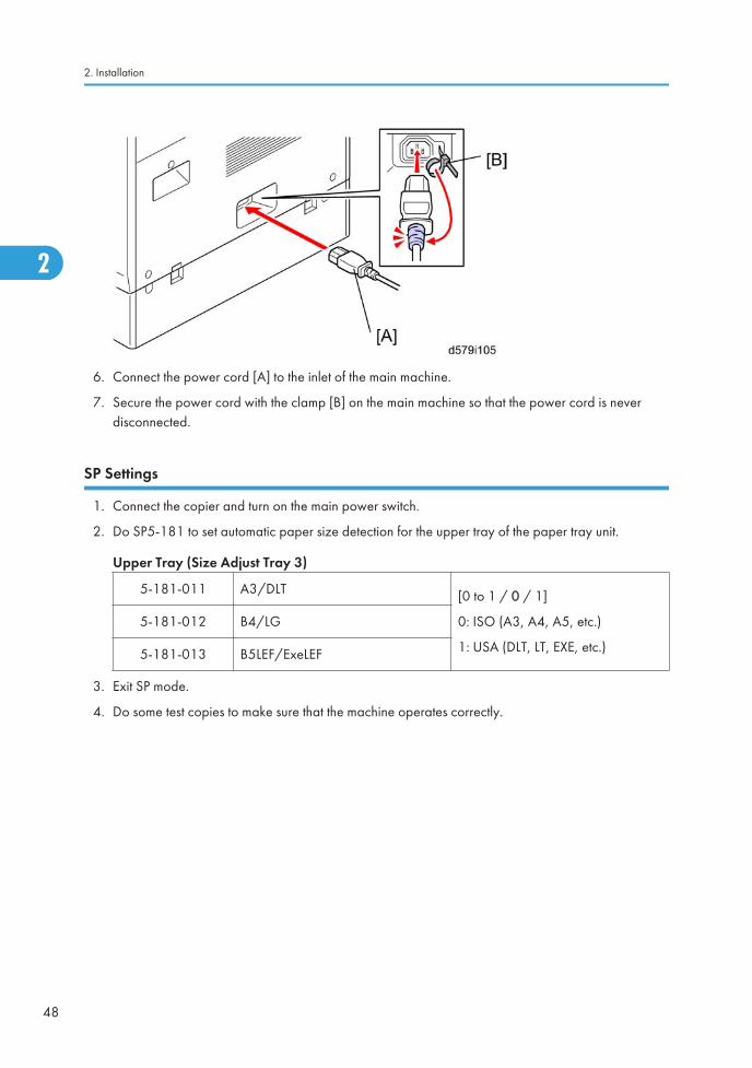
9. Connect the power cord [A] to the inlet [B] of the main machine.
10. Secure the power cord with the clamp [C] installed in the main machine so that the power cord isnever disconnected.
SP Settings
1. Turn on the main power switch.
Copier Installation
39
2

2. Go into the SP mode and do SP2-801 (Developer Initialization).
3. Do SP5-181 and SP1-007-007 to set automatic paper size selection for the upper tray, lowertray, and by-pass tray.
Upper Tray (Size Adjust Tray 1)
5-181-001 A4 LEF/LT LEF
[0 to 1 / 0 / 1]
0: ISO (A3, A4, A5, etc.)
1: USA (DLT, LT, EXE, etc.)
5-181-002 A3/DLT
5-181-003 B4/LG
5-181-004 B5LEF/ExeLEF
5-181-005 A5SEF/HLTSEF
Lower Tray (Size Adjust Tray 2)
5-181-006 A4 LEF/LT LEF
[0 to 1 / 0 / 1]
0: ISO (A3, A4, A5, etc.)
1: USA (DLT, LT, EXE, etc.)
5-181-007 A3/DLT
5-181-008 B4/LG
5-181-009 B5LEF/ExeLEF
By-Pass Tray (By-Pass Size Detection)
1-007-007 LTSEF/LG
[0 to 1 / 0 / 1]
0: ISO (A3, A4, A5, etc.)
1: USA (DLT, LT, EXE, etc.)
4. Enable the NIB and/or USB function.
• To enable the NIB function, enter the SP mode and set SP5-985-001 (On Board NIC) to"1"(Enable).
• To enable the USB function, enter the SP mode and set SP5-985-002 (On Board USB) to"1"(Enable).
5. Exit SP mode.
6. Do some test copies to make sure that the machine operates correctly.
Data Overwrite Security
Do the following procedure if a customer wants to use this function.
1. Do SP5-878-1(Option Setup - Data Overwrite Security) and touch [EXECUTE].
2. Go out of the SP mode, turn off the operation switch, then turn off the main power switch.
2. Installation
40
2

3. Turn the machine power on.
4. Press [User Tools] and select System Setting > Administrator Tools > Auto Erase Memory Setting >On
5. Exit from User Tools mode.
6. Check the display and make sure that the overwrite erase icon [A] is displayed.
7. Make a Sample Copy.
8. Check the overwrite erase icon.
• The icon [B] changes to [C] when job data is stored in the hard disk.
• The icon goes back to its usual shape [B] after this function has completed a data overwriteoperation to the hard disk.
9. Do SP5990-005 (SP print mode - Diagnostic Report).
10. Look at the report:
• Under "[ROM No./Firmware Version]" check the number and version number listed for "HDDFormat Option".
• Under "[Loading Program]" check the option number and version number listed for"GW_zoffy".
• These two version numbers should be identical.
11. Exit SP mode.
HDD Encryption
Do the following procedure if a customer wants to use this function.
1. Do SP5-878-2 (Option Setup - Encryption Option) and touch [EXECUTE]
2. Go out of the SP mode, turn off the operation switch, then turn off the main power switch.
3. Turn the machine power on.
4. Push [User Tools] and select System Setting > Administrator Tools > Machine Data EncryptionSetting.
Copier Installation
41
2

5. Press [Encrypt].
6. Select the data to be carried over to the hard disk and not to be reset
To carry all of the data over to the hard disk, select [All data].To carry over only the machinesetting data, select [File System Data Only]. To reset all of the data, select [Format All Data].
7. Press the [Start] Key.
The encryption key for backup data is printed.
App 2 Me Setting (SP models only)
SP models have Java VM and "App 2 Me" as a standard.
Do the following procedure if a customer wants to use this function.
1. Press "User Tools" key on the operation panel.
2. Touch the "Extended Feature Settings" button twice.
3. Touch the "App 2 Me" line in the Startup Setting tab.
2. Installation
42
2

4. Touch the "Extended Feature Info" tab on the LCD.
5. Touch the "App 2 Me" line.
6. Set the setting of "Auto Start" to "On".
7. Touch the "Exit" button.
8. Exit the "User Tools" settings.
Transporting the Machine
1. Do SP4-806-001 to move the scanner carriage from the home position. This prevents dust fromfalling into the machine during transportation.
Copier Installation
43
2

Paper Feed Unit PB3120 (D579)
Accessory Check
Check the quantity and condition of the accessories against the following list.
No. Description Q'ty
1 Screw - M4 x 10 2
2 Screw with Spring Washer - M4 x 10 1
3 Securing bracket 2
Installation Procedure
• Turn off the main power switch of the copier and unplug the power cord before you start theinstallation procedure.
• You need two or more persons to lift the copier. The copier is highly unstable when lifted by oneperson, and may cause human injury or property damage.
• Do not lift the copier with the paper feed unit installed. The handle and grips may be damaged.
• The one-tray paper feed unit must be installed on the caster table (D593). Prepare the caster tablefirst before installing this unit.
2. Installation
44
2

1. Remove all tape on the paper feed unit.
2. Remove the paper tray and remove all tapes and padding.
3. Put the paper tray unit on the caster table (D593).
• For details about the installation of the caster table, see the “Installation Procedure of CasterTable (D593)” in this section.
Paper Feed Unit PB3120 (D579)
45
2

4. Remove the grip cover [A] at the front right of the main machine if this cover is attached.
5. Pull out three grips, then hold the handle and grips, and put the copier [B] on the paper feed unit[C].
• You need two or more persons to lift the copier.
6. Attach the grip cover [A] to the main machine.
2. Installation
46
2

7. Attach the securing brackets [A] ( x 1; M4x10 each).
1. Remove the 1st and 2nc paper trays [A], and then secure the paper feed unit [B] ( springwasher x 1; M4x 10).
2. Reinstall the 1st and 2nd trays.
3. Attach the appropriate paper tray number decal [A] and paper size decal [B] above and belowthe line [C] on the tray of the paper feed unit.
• The paper tray number and size sheet is in the accessory box of the main machine.
4. Lock the caster stoppers for the front two casters under the paper feed unit.
5. Load paper into the paper tray and set the side fences and bottom fence.
Paper Feed Unit PB3120 (D579)
47
2
6. Connect the power cord [A] to the inlet of the main machine.
7. Secure the power cord with the clamp [B] on the main machine so that the power cord is neverdisconnected.
SP Settings
1. Connect the copier and turn on the main power switch.
2. Do SP5-181 to set automatic paper size detection for the upper tray of the paper tray unit.
Upper Tray (Size Adjust Tray 3)
5-181-011 A3/DLT [0 to 1 / 0 / 1]
0: ISO (A3, A4, A5, etc.)
1: USA (DLT, LT, EXE, etc.)
5-181-012 B4/LG
5-181-013 B5LEF/ExeLEF
3. Exit SP mode.
4. Do some test copies to make sure that the machine operates correctly.
2. Installation
48
2

Caster Table Type D (D593)
Component Check
No. Description Q’ty
1 Caster Table 1
2 Stud Screw 1
Installation Procedure
1. Put the caster table on a flat place.
Caster Table Type D (D593)
49
2

2. Remove the grip cover [A] at the front right of the main machine if this cover is attached.
3. Lift the mainframe or the one-tray paper feed unit [B], and then install it on the caster table [C].
4. Pull out the tray of the mainframe or the one-tray paper feed unit.
5. Secure the mainframe or the one-tray paper feed unit to the caster table (stud screw x 1)
2. Installation
50
2

6. Reinstall the tray(s) in the mainframe or the one-tray paper feed unit.
7. Adjust the five leveling adjustors of the caster table.
Caster Table Type D (D593)
51
2

Paper Feed Unit PB3130 (D580)
Accessory Check
Check the quantity and condition of the accessories against the following list.
No. Description Q'ty
1 Screw – M4 x 10 2
2 Screw with Spring Washer – M4 x 10 1
3 Securing Bracket 2
Installation Procedure
• Unplug the machine power cord before starting the following procedure.
• The handles of the main machine for lifting must be inserted inside the machine and locked unlessthese handles are used for the installation or relocation of the main machine.
• You need two or more persons to lift the copier. The copier is highly unstable when lifted by oneperson, and may cause human injury or property damage.
2. Installation
52
2

1. Remove all tape on the paper feed unit.
2. Remove the paper tray and remove all tapes and padding.
3. Remove the grip cover [A] at the front right of the main machine if this cover is attached.
4. Pull out three grips, then hold the handle and grips, and put the copier [B] on the paper feed unit[C].
Paper Feed Unit PB3130 (D580)
53
2

• You need two or more persons to lift the copier.
5. Attach the grip cover [A] to the main machine.
6. Attach a securing bracket [A] to each side of the paper tray unit, as shown ( x 1; M4x10 each).
7. Remove the 1st and 2nd paper trays [A].
8. Fasten the paper tray unit at [B] ( spring washer x 1; M4x10).
9. Reinstall the all paper trays.
2. Installation
54
2

10. Attach the appropriate paper tray number decal [A] and paper size decal [B] above and belowthe line [C] on each tray of the paper feed unit.
• The paper tray number and size sheet is in the accessory box of the main machine.
11. Lock the caster stoppers for the front two casters under the paper feed unit.
12. Load paper into the paper trays and set the side fences and bottom fence.
13. Connect the power cord [A] to the inlet of the main machine.
14. Secure the power cord with the clamp [B] on the main machine so that the power cord is neverdisconnected.
SP Settings
1. Connect the copier and turn on the main power switch.
Paper Feed Unit PB3130 (D580)
55
2

2. Do SP5-181 to set automatic paper size detection for the upper and lower tray of the paper trayunit.
Upper Tray (Size Adjust Tray 3)
5-181-011 A3/DLT [0 to 1 / 0 / 1]
0: ISO (A3, A4, A5, etc.)
1: USA (DLT, LT, EXE, etc.)
5-181-012 B4/LG
5-181-013 B5LEF/ExeLEF
Lower Tray (Size Adjust Tray 4)
5-181-014 A4/LEF
[0 to 1 / 0 / 1]
0: ISO (A3, A4, A5, etc.)
1: USA (DLT, LT, EXE, etc.)
5-181-015 B3/DLT
5-181-016 B4/LG
5-181-017 B5LEF/ExeLEF
3. Exit SP mode.
4. Do some test copies to make sure that the machine operates correctly.
2. Installation
56
2
LCIT PB3140 (D581)
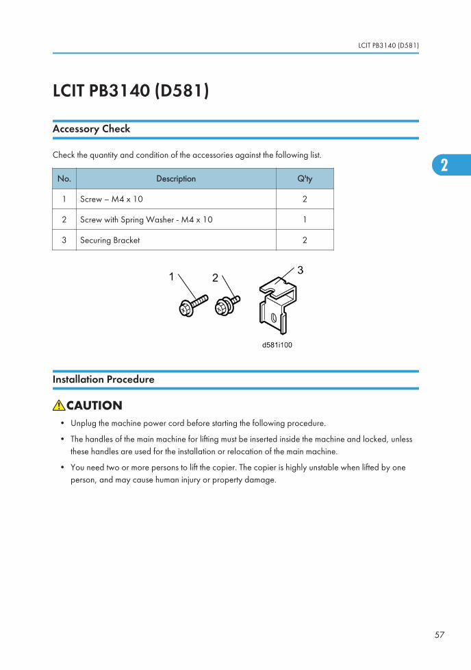
Accessory Check
Check the quantity and condition of the accessories against the following list.
No. Description Q'ty
1 Screw – M4 x 10 2
2 Screw with Spring Washer - M4 x 10 1
3 Securing Bracket 2
Installation Procedure
• Unplug the machine power cord before starting the following procedure.
• The handles of the main machine for lifting must be inserted inside the machine and locked, unlessthese handles are used for the installation or relocation of the main machine.
• You need two or more persons to lift the copier. The copier is highly unstable when lifted by oneperson, and may cause human injury or property damage.
LCIT PB3140 (D581)
57
2

1. Remove the strips of tape.
2. Remove the grip cover [A] at the front right of the main machine if this cover is attached.
3. Pull out three grips, then hold the handle and grips, and put the copier [B] on the LCT [C].
• You need two or more persons to lift the copier.
4. Attach the grip cover [A] to the main machine.
2. Installation
58
2

5. Attach a securing bracket [A] to each side of the LCT, as shown ( x 1; M4x10 each).
6. Remove the 1st and 2nd paper trays [A], and then secure the LCT [B] ( spring washer x 1;M4x10).
7. Reinstall the 1st and 2nd paper trays.
LCIT PB3140 (D581)
59
2

8. Attach the appropriate paper tray number decal [A] and paper size decal [B] to the line [C] on thetray of the LCT.
• The paper tray number and size sheet is in the accessory box of the main machine.
9. Lock the caster stoppers for the front two casters under the paper feed unit.
10. Load paper into the LCT.
11. Connect the power cord [A] to the inlet of the main machine.
12. Secure the power cord with the clamp [B] on the main machine so that the power cord is neverdisconnected.
SP Settings
1. Connect the copier and turn the main machine on.
2. Installation
60
2

2. Do SP5-181-010 to set automatic paper size detection for the LCT paper tray.
LCT Paper Tray (Size Adjust Tray 3 / LCT)
5-181-010 A4 LEF/LT LEF
[0 to 1 / 0 / 1]
0: ISO (A3, A4, A5, etc.)
1: USA (DLT, LT, EXE, etc.)
3. Exit SP mode.
4. Do some test copies to make sure that the machine operates correctly.
LCIT PB3140 (D581)
61
2

ARDF DF3060 (D578)
Component Check
Check the quantity and condition of the accessories against the following list.
No. Description Q'ty
1 ARDF 1
2Original Setting and ARDF Exposure Glass CleaningDecal
1
3 Stamp Cartridge 1
4 Knob Screw 2
5 Stud Screw 2
2. Installation
62
2

Installation Procedure
• Unplug the copier power cord before starting the following procedure.
1. Remove all tapes and shipping retainers.
• When unloading the ARDF from a pallet, hold the front and rear side of the ARDF.
2. Insert the two stud screws [A] on the top of the machine.
ARDF DF3060 (D578)
63
2

3. Mount the ARDF [A] by aligning the screw keyholes [B] of the ARDF support plate over the studscrews.
4. Slide the ARDF toward the front of the machine.
5. Secure the ARDF with the two knob screws [C].
6. Attach the interface cable [D] to the inlet of the machine.
7. Install the stamp cartridge [A] in the ARDF.
2. Installation
64
2

8. Peel off the platen sheet [A] and place it on the exposure glass.
9. Align the rear left corner (of the platen sheet) with the corner on the exposure glass.
10. Close the ARDF.
11. Open the ARDF and check that the platen sheet is correctly attached.
12. Attach the original setting and ARDF exposure glass cleaning decal [A] to the top cover as shown.
13. Plug in and turn on the main power switch, and then check the ARDF operation.
14. Make a full size copy. Check that the registrations (side-to side and leading edge) and image skeware correct. If they are not, adjust the registrations and image skew, referring to the service manual("Copy Adjustments" in the "Replacements and Adjustments").
ARDF DF3060 (D578)
65
2

1 Bin Tray BN3090 (D582)
Component Check
Check the quantity and condition of the components against the following list.
No. Description Q'ty
1 Support Bar Cover 1
2 Tray Support Bar 1
3 Guide Mylar 1
4 1 Bin Tray Unit 1
5 Tray 1
6 Tapping Screw M3 x 8 2
Installation Procedure
• Unplug the copier power cord before starting the following procedure.
1. Remove all tapes.
2. Installation
66
2

2. If the optional bridge unit has been installed, open the right guide [A] of the bridge unit.
-or-
If the optional bridge unit is not installed, skip this step.
3. Open the right cover [A].
4. Remove the front right cover [B] ( x 1).
5. Remove the left frame cover [C] ( x 1).
• Keep this screw for a later step.
6. Take out the duplex tray [D].
1 Bin Tray BN3090 (D582)
67
2

7. Remove the fusing fan [A] ( x 2, x 1)
8. Remove the duplex guide [B] ( x 1).
• Keep this screw for a later step.
2. Installation
68
2

9. Remove the harness from the clamp [A].
10. Install the 1-bin tray unit [B] ( x 1, x 2).
• Use the screw which was removed in step 8.
11. Re-install the fusing fan ( x 2) and front right cover ( x 1).
12. Peel off the double sided tapes [A] from the guide mylar [B].
13. Attach the guide mylar [A] so that the short edge of the guide mylar is aligned with the sloping part[B] of the scanner unit bottom frame.
1 Bin Tray BN3090 (D582)
69
2

14. Install the tray support bar [A] ( x 2) in the left frame [B] of the main machine.
15. Install the tray [A], and then attach the tray to the tray support bar [B] ( x 1, x 1).
16. Attach the support bar cover [C] ( x 1).
• Use the screw which was removed in step 5.
17. Turn on the main power switch and check the 1-bin tray unit operation.
2. Installation
70
2

Internal Shift Tray SH3050 (D583)
Component Check
Check the quantity and condition of the components against the following list.
No. Description Q'ty For this model
1 Shift Tray Unit 1 Yes
2 Drawer Cover 1 Yes
3 Base 1 Yes
Installation Procedure
• Unplug the copier power cord before starting the following procedure.
1. Remove all tapes.
Internal Shift Tray SH3050 (D583)
71
2

2. Attach the drawer cover [A] to the shift tray unit [B].
3. Remove the inner tray [A].
4. Remove the connector cover [B] ( x 1).
5. Install the shift tray base [A].
2. Installation
72
2

6. Install the shift tray unit [A], as shown.
7. Turn on the main power switch and check the shift tray operation.
Internal Shift Tray SH3050 (D583)
73
2

Bridge Unit BU3050 (D584)
Component List
Check the quantity and condition of the components against the following list.
No. Description Q’ty
1 Bridge Unit 1
2 Wide Extension Tray 1
3 Shoulder Screw 1
4 Screw 1
Installation Procedure
• Unplug the copier power cord before starting the following procedure.
2. Installation
74
2

Only when installing this unit for use with Booklet Finisher (D589)
Replace the extension tray [A] with the wide extension tray [B] in the accessories of this unit only whenBooklet Finisher (D589) is attached to the machine.
Installation Procedure
1. Open the right cover [A].
2. Remove the front right cover [B] ( x 1).
3. Remove the inner tray [C].
4. Remove the connector cover [D] ( x 1).
Bridge Unit BU3050 (D584)
75
2

5. Install the bridge unit [A], and then secure it ( shoulder screw x 1).
• Open the bridge right cover [B] to secure the right screw.
6. Reinstall the front right cover ( x 1).
7. Install the optional finisher (refer to the finisher installation procedure).
2. Installation
76
2

Finisher SR3090 (D588)
Accessory Check
Check the quantity and condition of the accessories against the following list.
No. Description Q'ty For this model
1 Grounding Plate 1 Yes
2 Rear Joint Bracket 1 Yes
3 Front Joint Bracket 1 Yes
4 Rear Joint Bracket 1 Not used
5 Copy Tray 1 Yes
6 Screw - M3 x 8 1 Yes
7 Screw - M4 x 13 4 Not used
8 Knob Screw - M3 x 8 1 Yes
9 Knob Screw - M4 x 10 1 Yes
10 Screw - M4 x 25 3 Yes
11 Staple Position Decal 1 Yes
Finisher SR3090 (D588)
77
2

Installation Procedure
• Unplug the main machine power cord before starting the following procedure.
The following options must be installed before you install this finisher:
• Bridge Unit (D584) and either Paper Feed Unit (D580) or LCT (D581)
1. Unpack the finisher and remove the tapes.
• Be sure to keep screw [A]. It will be needed to secure the grounding plate in step 3.
2. Install the rear joint bracket [A] ( x 1; M4x25) and front joint bracket [B] ( x 2; M4x25).
2. Installation
78
2

3. Install the grounding plate [A] on the finisher ( x 2; M3x8).
• Use the screw removed in step 1 and the screw from the accessory box.
4. Open the front door [B]. Then pull the locking lever [C].
5. Align the finisher on the joint brackets, and lock it in place by pushing the locking lever.
6. Secure the locking lever ( x 1; knob M3x8) and close the front door.
7. Install the copy tray [D] ( x 1; knob M4x10).
8. Connect the finisher cable [E] to the main machine.
Finisher SR3090 (D588)
79
2

9. Attach the staple position decal [A] to the ARDF as shown.
10. Turn on the main power switch and check the finisher operation.
2. Installation
80
2

Booklet Finisher SR3100 (D589)
Accessory Check
Check the quantity and condition of the components against the following list.
No. Description Q’ty For This Model
1 Rear Joint Bracket 1 Yes
2 Rear Joint Bracket 1 Not used
3 Front Joint Bracket 1 Yes
4 Grounding Plate 1 Yes
5 Upper Output Tray 1 Yes
6 Lower Output Tray 2 Yes
7 Short Knob screw 1 Yes
8 Long Knob screw 1 Yes
9 Screw (M4 x 13) 4 Not used
10 Screw (M3 x 8) 2 Yes
11 Screw (M4 x 25) 3 Yes
12 Cushion 2 Yes
Booklet Finisher SR3100 (D589)
81
2

Installation Procedure
• Unplug the machine power cord before starting the following procedure.
Some optional units must be installed before installing this finisher (D589). Refer to the following:
• Bridge Unit (D584) and either PFU (D580) or LCT (D581)
1. Unpack the finisher and remove all tapes and packing materials from the finisher.
2. Installation
82
2

2. Open the front door [A] of the 1000-sheet booklet finisher, and then pull out the jogger unit [B].
3. Remove all tapes and packing materials from the inside of the finisher.
4. Attach the cushions [A] to the finisher.
• Make sure that the cushions are placed within 0 to 1 mm [B] from the edge of the cover orframe.
5. Install the ground plate [C] on the finisher [D] ( x 2; M3x8).
Booklet Finisher SR3100 (D589)
83
2

6. Attach the rear joint bracket [A] ( x 1; M4x25).
7. Attach the front joint bracket [B] ( x 2; M4x25).
8. Slowly push the finisher to the left side of the machine, keeping its front door open until the brackets[A] [B] go into their slots.
9. Push the lock lever [C], and then secure it (Long knob screw x 1).
10. Close the front door of the finisher.
11. Connect the finisher connector [D] to the machine.
2. Installation
84
2

12. Install the upper output tray [A] (short knob screw x 1).
13. Install the lower output tray [B].
14. Turn on the main power switch.
15. Check the 1000-sheet booklet finisher operation.
Booklet Finisher SR3100 (D589)
85
2

Punch Kit PU3000 (B807)
Component Check
Check the quantity and condition of the components against the following list.
No. Description Q’ty
1 Punch Unit 1
2 Punch Drive Motor 1
3 Hopper Full Sensor Arm 1
4 Sub-scan Registration Sensor Unit 1
5 Punch Unit Stay 1
6 Sub-scan Registration Sensor Guide 1
7 Hopper 1
8 Screw 8
9 Step Screw 1
10 Spring 1
2. Installation
86
2

Installation
• Unplug the main machine power cord before starting the following procedure. If the 1000-sheetbooklet finisher has been installed, disconnect it and pull it away from the machine.
Punch Kit PU3000 (B807)
87
2
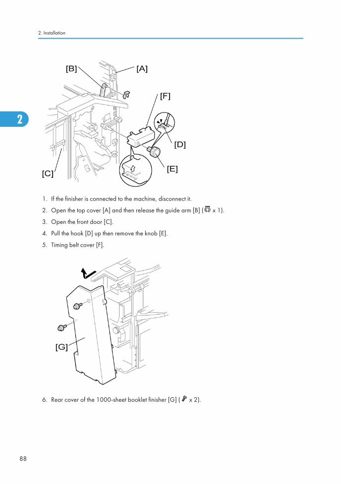
1. If the finisher is connected to the machine, disconnect it.
2. Open the top cover [A] and then release the guide arm [B] ( x 1).
3. Open the front door [C].
4. Pull the hook [D] up then remove the knob [E].
5. Timing belt cover [F].
6. Rear cover of the 1000-sheet booklet finisher [G] ( x 2).
2. Installation
88
2

7. Cover bracket [H] ( x 1)
8. Remove the paper guide plate [I] from the rear side ( x 4).
9. Install the punch unit stay [J] from the front side ( x 3).
10. Install the sub-scan registration sensor guide [K] from the top ( x 1).
Punch Kit PU3000 (B807)
89
2

11. Remove the bracket [L] from the punch unit ( x 1).
12. Install the punch unit [M] along the punch unit stay from the rear side.
13. Make sure to put the punch unit stay pin [N] through the hole [O].
2. Installation
90
2

14. Connect the harnesses [P] to the main PCB.
15. Put the harnesses [Q] through the hole [R] in the rear frame ( x 1).
16. Install the punch drive motor [S] on the rear frame ( x 2).
17. Connect the drive motor harness [T] to the harness from the punch unit ( x 1).
18. Connect the home position sensor harness from the punch unit to the home position sensor [U].
Punch Kit PU3000 (B807)
91
2

19. Install the sub-scan registration sensor unit [V] from the rear side ( x 2).
20. Route and connect the harnesses as shown ( x 2).
21. Install the hopper full sensor arm [W] ( x 1, spring x 1).
22. Connect the harness from the sub-scan registration sensor unit to the hopper full sensor [X].
2. Installation
92
2

23. Install the hopper [Y] from the front side.
24. Reinstall the timing belt cover and knob.
25. Reinstall the rear cover ( x 2).
26. Close the front door and top cover.
27. Install the 1000-sheet booklet finisher on the copier.
28. Plug in and turn on the main power switch.
29. Check the 1000-sheet booklet finisher operation.
Punch Kit PU3000 (B807)
93
2

Finisher SR3070 (D585)
Accessory Check
Check the quantity and condition of the accessories against the following list.
No Description Q'ty For This Model
1 Unit Holder 1 Yes
2 Shift Tray 1 Yes
3 Holder Bracket 1 Yes
4 Screw: M3 x 8 4 Yes
5 Screw: M3 x 6 1 Yes
6 Screw: M4 x 14 4 Not used
7 Screw: M4 x 20 4 Yes
8 Screw: M4 x 25 3 Yes
9 Support Bracket 2 Yes
10 Support Bracket Cover 2 Yes
2. Installation
94
2

Installation Procedure
• Unplug the main machine power cord before starting the following procedure.
• Whenever you lift or carry the SR3070, always hold it by the bottom edges of the front and rearcovers, as shown below. If you do not, SC798 will occur when you attach the finisher. DO NOThold the finisher by the tray holder.
• Before you install Finisher SR3070, the optional bridge unit (D584) must be installed.
1. Unpack the finisher and remove the tapes.
Finisher SR3070 (D585)
95
2

2. Install the unit holder [A] ( x 3; M4x25).
3. Install the support brackets [B] ( x 2 each; M4x20).
4. Install the support bracket covers [C] ( x 1 each; M3x8).
5. Install the 500-sheet finisher [A].
6. Install the holder bracket [B] ( x 1; M3x6).
7. Connect the finisher cable [C].
2. Installation
96
2

8. Install the shift tray [A] ( x 2; M3x8).
9. Turn on the main power switch and check the finisher operation.
Finisher SR3070 (D585)
97
2

Internal Finisher Type 3352 (D586)This procedure explains how to install the internal finisher, without installing the punch unit at the sametime.
Component Check
Check the quantity and condition of the components against the following list.
No. Description Q’ty
1 Internal Finisher 1
2 Guide Rail 1
3 Stopper 1
4 Screw - M4 x 6 1
5 Bind Screw - M3 x 6 8
6 Screw - M3 x 6 2
7 Positioning Pin Bracket 1
8 Finisher Right Cover 1
9 Inner Bottom Plate 1
2. Installation
98
2

Installation Procedure
• Unplug the copier power cord before starting the following procedure.
Preparing before Installing the Internal Finisher
1. Remove all tapes from the internal finisher.
Internal Finisher Type 3352 (D586)
99
2
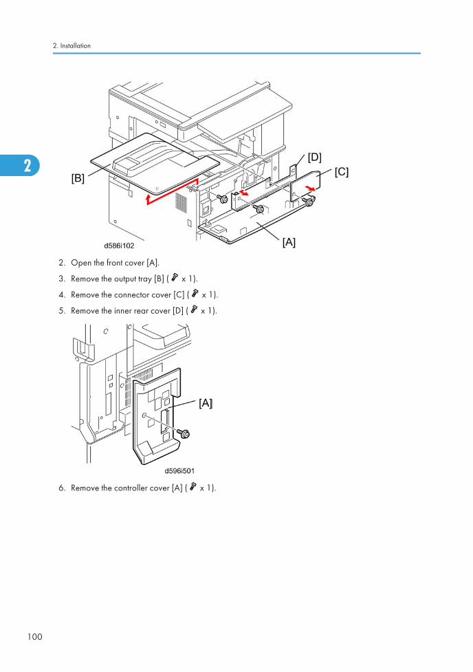
2. Open the front cover [A].
3. Remove the output tray [B] ( x 1).
4. Remove the connector cover [C] ( x 1).
5. Remove the inner rear cover [D] ( x 1).
6. Remove the controller cover [A] ( x 1).
2. Installation
100
2

7. Install the guide rail [A] in the front frame of the main machine ( bind screw x 3; M3x6).
8. Install the inner bottom plate [A] ( bind screw x 3; M3x6).
9. Install the positioning pin bracket [B] in the rear frame of the main machine ( x 1; M3x6).
Internal Finisher Type 3352 (D586)
101
2

Internal Finisher Installation
1. Attach the finisher right cover [A] to the guide rail [B] ( x 1; M3x6).
2. Install the internal finisher [A].
• Align the wheel [B] at the front of the internal finisher with the groove on the guide rail wheninstalling the internal finisher
3. Insert the rear rail [C] into the left frame of the main machine ( x 1: M4x6).
2. Installation
102
2

4. Push up the internal finisher [A] from the bottom, and then install the stopper [B] to the bottom sideof the internal finisher ( bind screw x 2; M3x6).
5. Push the internal finisher [A], and then connect the cable [B] to the inlet of the main machine.
6. Reassemble the machine.
7. Turn on the main power switch.
Internal Finisher Type 3352 (D586)
103
2

8. Check the internal finisher operation.
2. Installation
104
2

Punch Kit PU3020 (D587)This procedure explains how to install the punch kit for the internal finisher, after installing the internalfinisher.
Component Check
Check the quantity and condition of the components against the following list.
No. Description Q’ty
1 Punch Unit 1
2 Tray Lower Rear Cover 1
3 Punch Cover 1
4 Hopper 1
5 Screw: M3x6 7
6 Bracket 1
7 Tray Lower Front Cover 1
8 Front Right Lower Cover 1
Punch Kit PU3020 (D587)
105
2

Installation Procedure
• Unplug the copier power cord before starting the following procedure.
1. Remove the controller cover [A] ( x 1).
2. Disconnect the cable [A] from the inlet of the main machine.
3. Pull out the internal finisher [B].
2. Installation
106
2

4. Push up the internal finisher [A] from the bottom, and then remove the stopper [B] from the bottomside of the internal finisher ( x 2).
5. Remove the screw from the rear rail [A].
6. Remove the internal finisher [B] by pulling it off the main machine.
Punch Kit PU3020 (D587)
107
2

7. Remove the finisher right cover [A] from the guide rail [B] ( x 1).
8. Remove the bracket [C] form the guide rail.
9. Attach the bracket [A] removed in step 5 on the guide rail shown above.
2. Installation
108
2

10. Install the bracket [A] on the guide rail [B] ( x 1; M3x6).
11. Turn the internal finisher [A] over, and then remove the finisher front cover [B] ( x 1).
Punch Kit PU3020 (D587)
109
2

12. Install the front right lower cover for punch unit [A] on the internal finisher ( x 1; M3x6).
13. Install the tray lower rear cover [A] on the rear side of the internal finisher ( x 1; M3x6).
2. Installation
110
2

14. Install the tray lower front cover [A] on the internal finisher ( x 1; M3x6).
15. Attach the punch cover [A] to the punch unit [B].
Punch Kit PU3020 (D587)
111
2

16. Open the punch cover’s front door [A], and then secure the punch cover to the punch unit ( x 2:M3x6).
17. Install the punch unit [A] on the main machine.
2. Installation
112
2

18. Open the punch cover’s front door [A], and then secure the punch unit to the main machine ( x 2:M3x6).
19. Install the hopper [A] from the front.
Punch Kit PU3020 (D587)
113
2

20. Install the internal finisher [A].
• Align the wheel [B] at the front of the internal finisher with the groove on the guide rail wheninstalling the internal finisher
21. Insert the rear rail [C] into the left frame of the main machine ( x 1: M4x6).
2. Installation
114
2

22. Push up the internal finisher [A] from the bottom, and then install the stopper [B] to the bottom sideof the internal finisher ( bind screw x 2; M3x6).
23. Push the internal finisher [A], and then connect the cable [B] to the inlet of the main machine.
24. Reassemble the machine.
25. Turn on the main power switch.
26. Check the internal finisher operation.
Punch Kit PU3020 (D587)
115
2

Platen Cover (D597)
1. Install the platen cover [A] ( x 2).
2. Remove the platen [A] from the platen cover.
3. Align the platen on the exposure glass, and then close the platen cover.
2. Installation
116
2

Key Counter Bracket Type H (A674)
Installation Procedure
Preparing before installing the key counter bracket
1. Hold the key counter plate nuts [A] on the inside of the key counter bracket [B] and insert the keycounter holder [C].
2. Secure the key counter holder to the bracket ( x 2).
3. Install the key counter cover [D] ( x 2).
4. Remove:
• Upper rear cover ( p.181 "Upper Rear Cover")
• Right rear cover ( p.181 "Right Rear Cover")
Key Counter Bracket Type H (A674)
117
2

5. Cut off the part [A] of the right rear cover.
6. Connect the key counter harness to the connector [B] through the cut off part of the rear cover.
7. Peel off double sided tape on the key counter bracket and attach the key counter to the scannerright cover.
8. Reassemble the machine.
2. Installation
118
2

Optional Counter Interface Unit Type A (B870)
Installation Procedure
1. Remove the upper rear cover. ( p.181 "Upper Rear Cover")
2. Install the four stud stays in the location [A].
3. Install the optional counter interface board on the four stud stays.
4. Connect the harness to CN3 [A] on the optional counter interface board.
Optional Counter Interface Unit Type A (B870)
119
2

5. Connect the other terminal of the harness to "CN345" [A] on the BCU.
6. Route the harness [A] and clamp it with four clamps as shown above ( x 4).
7. Remove the right rear cover. ( p.181 "Right Rear Cover")
2. Installation
120
2

8. Cut off the part [A] of the right rear cover.
9. Connect the harness from the optional counter device to "CN4" [A] on the optional counterinterface board through the cut off part of the right rear cover.
10. Reassemble the machine.
Optional Counter Interface Unit Type A (B870)
121
2

Heaters
Anti-Condensation Heater (Scanner Unit)
Installation Procedure
1. Remove the upper rear cover. ( p.181 "Upper Rear Cover")
2. Open the ARDF or platen cover.
3. Remove:
• [A] Glass cover ( x 4)
• [B] ARDF exposure glass
• [C] Rear scale ( x 3)
• [D] Exposure glass with left scale
2. Installation
122
2

4. Move the scanner carriage to the right side by rotating the scanner motor [A].
5. Put the heater connector through the cut out.
6. Connect the heater connector to [A] in the frame of the machine ( x 1).
Heaters
123
2
7. Install the heater in the scanner unit ( x 1).
8. Secure the cable cover [A] and the left side of the heater ( x 1).
9. Reassemble the machine.
Tray Heater (Copier)
• Disconnect the copier power cord before you start this procedure.
1. Pull out the 1st and 2nd paper trays.
2. Remove the lower rear cover ( p.181 "Lower Rear Cover").
3. Remove the bracket [A] from the main machine ( x 1).
2. Installation
124
2

4. Connect the heater cable to the ac cable at [A].
5. Install the tray heater assembly [A] ( x 1).
6. Reassemble the main machine and 1st and 2nd paper trays.
Tray Heater (Optional Paper Feed Unit)
For Installing the Tray Heater in D579
• Disconnect the copier power cord before you start this procedure.
Heaters
125
2

1. If the optional paper feed unit has been installed to the main machine, remove it from the mainmahchine.
2. Pull out the tray in the optional paper feed unit.
1. Remove the rear cover [A] of the optional paper feed unit ( x 2).
2. Remove the upper stays [A] ( x 8).
2. Installation
126
2

3. Remove the harness from the clamps ( x 5 : red arrows).
4. Remove the cables from the connectors ( x 2 : blue arrows).
5. Remove the upper rear stay [A] ( x 8).
Heaters
127
2
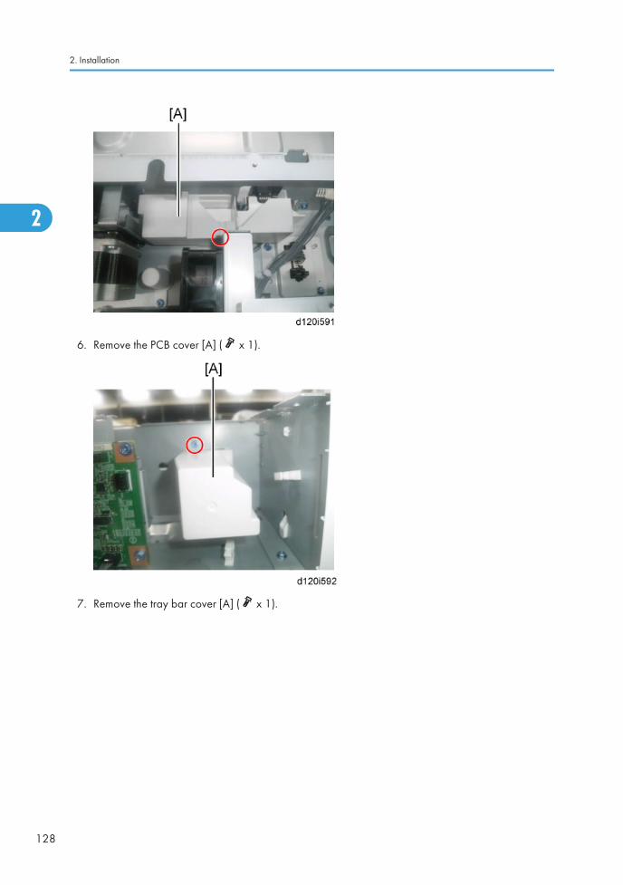
6. Remove the PCB cover [A] ( x 1).
7. Remove the tray bar cover [A] ( x 1).
2. Installation
128
2

8. Install the tray heater [A] in the optional paper feed unit ( x 1).
9. Connect the harness [A] to the connector [B] of the tray heater ( x 2).
Heaters
129
2

10. Route the harness [A] as shown and clamp it with two clamps ( x 2).
11. Reassemble the optional paper feed unit except the rear cover.
12. Install the paper feed unit to the main machine.
13. Remove the upper rear cover [A] ( x 5).
2. Installation
130
2

14. Remove the lower rear cover [A] ( x 4).
15. Remove the harness cover bracket [A] from the main frame ( x 1).
Heaters
131
2

16. Pass the harness from the lower paper feed unit through the hole [A].
17. Connect the harness [A] to the connector [B] of the main frame.
18. Reassemble the main machine and optional paper feed unit.
For Installing the Tray Heater in D580
• Disconnect the copier power cord before you start this procedure.
1. Pull out the two trays in the optional paper feed unit.
2. Remove the joint bracket [A] ( x 1 each).
2. Installation
132
2

3. Remove the cover [B] for the optional paper tray unit ( x 2).
4. Pass the heater cable through the opening [A], and then install the tray heater in the optional paperfeed unit ( x1).
5. Remove:
• Upper rear cover ( p.181 "Upper Rear Cover")
• Right rear cover ( p.181 "Right Rear Cover")
6. Remove the harness cover bracket [A] from the main frame ( x 1).
Heaters
133
2

7. Connect the harness [A] to the connector [B] of the tray heater.
8. Route the harness [A] and clamp it as shown ( x 3).
9. Connect the harness [A] to the connector [C] of the main frame through the hole [D].
10. Reassemble the main machine and optional paper feed unit.
Tray Heater (Optional LCT)
1. Pull out the LCT drawer.
• If the right tray comes out with the left tray, push the right tray into the LCT.
2. Installation
134
2

2. Remove the left tray [A] ( x 2).
3. Remove the right tray [A] while pressing down the stopper [B].
• While reinstalling the right tray, set the right tray on the guide rail and carefully push the trayin, making sure to keep the tray level.
Heaters
135
2

4. Remove the two securing brackets [A] ( x 1 each), and then the rear cover [B] of the optional LCT( x 2).
5. Pass the heater cable through the opening [A], and then install the tray heater in the optional paperLCT ( x1).
6. Remove:
• Upper rear cover ( p.181 "Upper Rear Cover")
• Right rear cover ( p.181 "Right Rear Cover")
2. Installation
136
2
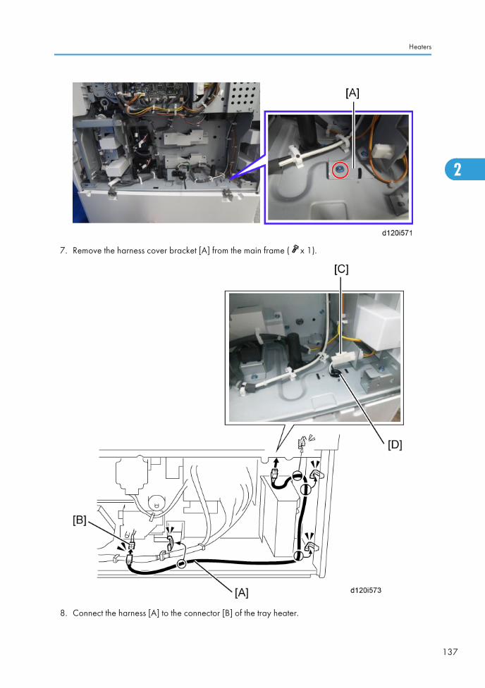
7. Remove the harness cover bracket [A] from the main frame ( x 1).
8. Connect the harness [A] to the connector [B] of the tray heater.
Heaters
137
2

9. Route the harness [A] and clamp it with four clamps as shown ( x 4).
10. Connect the harness [A] to the connector [C] of the main frame through the hole [D].
11. Reassemble the mainframe and the optional LCT.
2. Installation
138
2

Mechanical CounterThis counter is only used for NA models.
Accessory Check
No. Description Q’ty
1 Mechanical counter 1
Installation
• Unplug the machine power cord before starting the following procedure.
1. Remove:
• Output tray ( p.185 "Output Tray")
• Front door ( p.178 "Front Door")
2. Remove the screw [A] of the left cover.
Mechanical Counter
139
2

3. Remove the front inner cover [A] ( x 4).
4. Push the mechanical counter [A] into the machine.
5. Connect the harness [A] to the mechanical counter.
6. Reassemble the machine.
2. Installation
140
2

Copy Data Security Unit Type F (B829)
Component Check
No. Description Q’ty For this model
1 ICIB-3 1 Yes
2 Flexible cable: Long 1 Not used
3 Flexible cable: Short 1 Not used
4 Harness 1 Not used
5 Harness with bands 1 Not used
6 Small Bracket 1 Yes
7 Saddle Clamp 1 Not used
8 Screws: M3x6 6 Yes
9 Bracket 1 Not used
Installation
• Unplug the main machine power cord before you do the following procedure.
1. Remove the upper rear cover. ( p.181 "Upper Rear Cover")
Copy Data Security Unit Type F (B829)
141
2
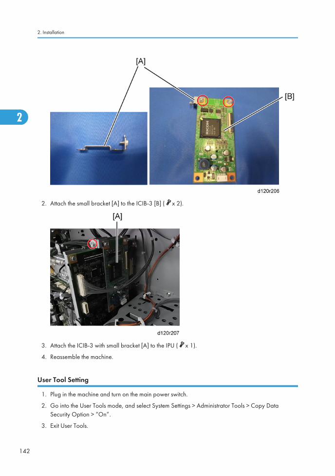
2. Attach the small bracket [A] to the ICIB-3 [B] ( x 2).
3. Attach the ICIB-3 with small bracket [A] to the IPU ( x 1).
4. Reassemble the machine.
User Tool Setting
1. Plug in the machine and turn on the main power switch.
2. Go into the User Tools mode, and select System Settings > Administrator Tools > Copy DataSecurity Option > “On”.
3. Exit User Tools.
2. Installation
142
2

4. Check the operation.
• The machine will issue an SC165 error if the machine is powered on with the ICIB-3 removedand the “Data Security for Copying“ feature set to “ON”.
• The machine will issue an uncertain SC165 error if ICIB-3 is defective when the machine ispowered on and the “Data Security for Copying“ feature is set to “OFF”.
• When you remove this option from the machine, first set this feature to “OFF” with the user toolbefore removing this board. If you forget to do this, “Data Security for Copying “featurecannot appear in the user tool setting. Also, SC165 will appear every time the machine isswitched on, and the machine cannot be used.
5. Make sure that the machine can recognize the option.
Copy Data Security Unit Type F (B829)
143
2

Hard Disk (D594)
Accessory Check
No. Description Q’ty
1 HDD Unit 1
2 Screw 4
3 Connecting Board Unit 1
4 Keytop: Copy 2
5 Keytop: Document Server 2
6 Harness clamp 1
Installation
1. Remove the controller board unit. ( p.258 "Controller Board")
2. Remove the screw [A] on the controller board.
2. Installation
144
2

3. Install the HDD unit [A] on the controller board unit ( x 3). Use the screw removed in step 2 at[B].
Hard Disk (D594)
145
2
4. Connect the two cables [A] from the HDD unit to the connecting board [B] ( x 2).
5. Install the connecting board unit [A] on the controller board ( x 2).
6. Install the harness clamp [B] on the HDD unit.
2. Installation
146
2

7. Clamp the cables [A] to prevent them from sticking out.
8. Reinstall the controller board with the HDD.
9. Remove the 1st and 2nd blank key tops.
10. Replace the blank key tops with the key tops received in the kit from top to bottom:
• 1st Copy
• 2nd Document Server
After Installing the HDD
1. Do SP5-832-001 to format the hard disk.
2. Do SP5-853-001 to copy the preset stamp data from the firmware to the hard disk.
3. Do SP5-846-040 to copy the address book to the hard disk from the controller board.
Hard Disk (D594)
147
2

4. Do SP5-846-041 to let the user get access to the address book.
5. Turn the main power switch off and on.
2. Installation
148
2

File Format Converter Type E (D377)
Accessory Check
Check the accessories and their quantities against this list:
Description Q'ty
1. File Format Converter (MLB: Media Link Board) 1
Installation
1. Turn off the main power switch.
2. Remove the controller cover [A] ( x1).
3. Remove the board slot cover [B] ( x2).
File Format Converter Type E (D377)
149
2

4. Touch a metal surface to discharge any static electricity from your hands.
5. Set the interface board [C] in the open slot.
6. Confirm that the board is inserted completely, then fasten it ( x 2).
7. Turn on the main power switch.
8. Enter the SP mode and do SP5-990 to print an SMC Report.
9. Read the report and confirm that the interface board is installed correctly.
2. Installation
150
2

Browser Unit Type E (D430)
Accessories
Check the accessories and their quantities against the table below.
Description Q’ty
Browser Unit D430 SD Card 1
Installation
This option requires a HDD unit.
1. Switch the machine off.
2. Remove the controller cover [A] ( x1).
3. Insert the browser SD card [B] into SD card slot 1 or slot 2.
Browser Unit Type E (D430)
151
2

4. Turn on the main power switch.
5. Push [User Tools]> [Login/Logout].
6. Login with the administrator user name and password.
7. Touch "Extended Feature Settings" twice.
8. Touch "SD Card" then touch the "Browser" line.
9. Under "Install to:" touch "Machine HDD"> "Next".
10. When you see "Ready to Install", check the information on the screen to confirm your previousselection.
11. Touch "OK". You will see "Installing…" then "Completed".
12. Touch "Exit" twice to return to the copy screen.
13. Turn off the main power switch.
14. Install the key for “Browser Unit” to the place where you want it.
15. Turn on the main power switch.
16. When the machine reaches the Ready condition, press the key that you installed in Step 14 above.
• A message will be displayed confirming that the browser option was successfully installed.
17. Turn off the main power switch.
18. Remove the SD card from the slot.
19. Attach the slot cover.
20. Tell a customer to keep the SD card in a safe place after you have installed the applicationprogram from the card to the HDD.
This is because:
• The SD card is the only proof that the user is licensed to use the application program.
• You may need to check the SD card and its data to solve a problem in the future.
2. Installation
152
2
VM Card Type N (D594)This option is only for basic models.
Accessories
Check the accessories and their quantities against the table below.
Description Q'ty
1. VM SD Card 1
2. Decal 1
Installation
1. Switch the machine off.
2. Remove the controller cover [A] ( x1).
VM Card Type N (D594)
153
2

3. Insert the SD card [B] into SD Slot 2 (lower).
• This SD card must be inserted into Slot 2, the lower slot.
2. Installation
154
2

USB2.0/SD Slot Type H (D594)
Accessory Check
Check the quantity and condition of the accessories against the following list.
No. Description Q’ty
1 USB2.0/SD Slot 1
2 Ground Plate 1
3 USB Cable 1
4 Screw: M3 x 6 blue 1
5 Screw: M3 x 8 4
6Screw: M3 x 6 (Used when the booklet finisher (D589)has been installed)
1
7Bracket (Used when the booklet finisher (D589) hasbeen installed)
1
8Ground wire (Used when the booklet finisher has beeninstalled)
1
9 Hook and loop fastener 1
10 Decal 1
11 Decal Small 1
Installation Procedure
• If the optional booklet finisher has been installed, see the procedure in “Installation if the optionalbooklet finisher has been installed” in this section.
USB2.0/SD Slot Type H (D594)
155
2

1. Connect the USB cable [B] to the USB slot [A] in the USB2.0/SD Slot as shown above.
2. Attach the ground plate [C] to the bracket of the USB2.0/SD Slot ( x 1: M3x6 blue).
3. Remove the upper left cover. ( p.180 "Upper Left Cover")
4. Remove the part [A] of the upper left cover with pliers or a similar tool.
2. Installation
156
2

5. Remove the part [A] on the upper left cover.
6. Make four holes in the upper left cover with a screwdriver as shown [B].
• Smooth the four holes in the upper left cover as shown [B].
7. Put the USB cable [A] through the cutout in the upper left cover.
USB2.0/SD Slot Type H (D594)
157
2

8. Secure the USB2.0/SD Slot [A] with the upper left cover as shown above ( x 4: M3x8).
• Use the screw holes [B] as shown above.
9. Route the USB cable through the gaps in the upper left cover.
2. Installation
158
2

10. Remove the controller cover [A] ( x1), and then cut out the cover for the USB-A slots.
11. Attach the upper left cover [A] to the mainframe ( x 2).
12. Reattach the controller cover ( x 1).
13. Connect the USB cable [B] to USB-A as shown above.
14. Plug in and turn on the main power switch.
15. Change the setting of Printer SP1-013-002 from "0" to "1".
16. Change the setting of Printer SP1-110-002 from "0" to "1".
17. Exit the SP mode, and then check the operation of the USB2.0/SD Slot.
USB2.0/SD Slot Type H (D594)
159
2

18. Attach the decals [A] to the USB2.0/SD Slot as shown above.
Installation if the optional booklet finisher has been installed
1. Connect the USB cable [B] to the USB slot [A] in the USB2.0/SD slot as shown above.
2. Connect the ground wire [C] to [D] in the USB2.0/SD Slot ( x 1: M3x6 blue).
2. Installation
160
2

3. Cut out the part [A] on the back of the USB 2.0/SD slot with pliers or a similar tool, and route theUSB cable and ground wire through [A].
4. Install the right cover [B] of the USB2.0/SD Slot [C] ( x 2).
5. Remove the optional booklet finisher from the left side of the machine ( x 1).
6. Remove the controller cover [A] ( x1), and then cut out the cover for the USB-A slots.
7. Remove the upper left cover. ( p.180 "Upper Left Cover")
USB2.0/SD Slot Type H (D594)
161
2

8. Remove the part [A] of the upper left cover with pliers or a similar tool.
9. Secure the ground wire to the location [A] ( x 1).
2. Installation
162
2

10. Reassemble the machine and route the ground wire [A] through the cutout in the upper left cover.
11. Connect the USB cable [B] to USB-A.
12. Install the optional booklet finisher to the left side of the machine.
13. Peel off the backing paper from one side of the hook and loop fastener, and then stick it to thebottom of the USB2.0/SD slot [A].
14. Remove the other backing paper from the hook and loop fastener, and then attach the USB 2.0/SD slot [B] to the middle position on the back of the optional booklet finisher [C].
15. Plug in and turn on the main power switch.
16. Change the setting of Printer SP1-013-002 from "0" to "1".
17. Change the setting of Printer SP1-110-002 from "0" to "1".
18. Exit the SP mode, and then turn off the main power switch.
19. Check the operation of the USB2.0/SD Slot.
USB2.0/SD Slot Type H (D594)
163
2

20. Attach the decals [A] to the USB2.0/SD Slot as shown above.
Testing the SD Card/USB Slot
1. Insert an SD card or USB memory device in the slot.
You can connect only one removable memory device at a time.
2. Close the media slot cover.
If you leave the cover open, static electricity conducted through an inserted SD card could causethe machine to malfunction.
3. Make sure that no previous settings remain.
If a previous setting remains, press the [Clear Modes] key.
4. Place an original on the exposure glass.
5. Press [Store File].
6. Press [Store to Memory Device].
7. Press [OK].
8. Press the [Start] key.
When writing is complete, a confirmation message appears.
9. Press [Exit].
10. Remove the memory device from the media slot.
• Do not remove the memory device while writing is in process.
2. Installation
164
2

Card Reader Bracket Type C3352 (D593)
Component Check
Check the quantity and condition of the accessories against the following list.
No Description Q'ty For This Model
1 Screw: M3 x 8 2 Yes
2 Screw: M3 x 14 1 Not used
3 Screw: M4 x 25 1 Yes
4 Tapping Screw: M3 x 10 3 Yes
5 Upper Tray 1 Yes
6 Lower Tray 1 Yes
7 Tray Bracket 1 Yes
Installation Procedure
1. Remove the upper right cover. ( p.182 " Upper Right Cover")
Card Reader Bracket Type C3352 (D593)
165
2

2. Remove the cover [A] from the upper right cover.
3. Make 3 holes for the M4 screw in the upper right cover with a screwdriver.
• Do not open the 2 holes for the M3 screws all the way. This will make it impossible to tightenthe M4 screw.
2. Installation
166
2

4. Put the device cable through the hole in the upper right cover.
5. Route the cable in the upper right cover
6. Reattach the upper right cover ( x 2).
Card Reader Bracket Type C3352 (D593)
167
2

7. Attach the tray bracket [A] to the upper right cover ( [B] x 2: M3x8 tapping screw, [C] x 1:M4x25).
• For this model, use the screw holes marked "4" on the table bracket.
8. Attach the lower tray [A] to the tray bracket ( x 2: M3x8).
9. Attach the upper tray [B] to the tray bracket ( x 1: M3x8).
10. Connect the cable to the designated connector (the connector to use depends on the type of deviceto be connected).
If you install the device with USB cable.
1. Remove the upper rear cover. ( p.181 "Upper Rear Cover")
2. Installation
168
2

2. Route the cable as shown above.
3. Remove the upper left cover. ( p.180 "Upper Left Cover")
4. Remove the cut off part [A] of the upper left cover with pliers or a similar tool.
5. Reattach the upper left cover.
Card Reader Bracket Type C3352 (D593)
169
2

6. Route the cable through the cut off part of the upper left cover [A], and then connect the cable tothe designated connector (the connector to use depends on the type of device to be connected).
7. Reassemble the machine.
2. Installation
170
2

3. Preventive Maintenance
PM TablesSee "Appendices" for the following information:
• PM Tables
171
3

3. Preventive Maintenance
172
3

4. Replacement and Adjustment
Beforehand
• Before installing options, please do the following:
• If there is a fax unit in the machine, print out all messages stored in the memory, the lists of user-programmed items, and the system parameter list.
• If there are printer jobs in the machine, print out all jobs in the printer buffer.
• Turn off the main power switch and disconnect the power cord, the telephone line, and the networkcable.
• Always touch a grounded surface to discharge static electricity from your hands before you handleSD cards, printed circuit boards, or memory boards.
173
4

Special Tools and Lubricants
Special Tools
No. Part No. Description Q'ty Availability
1 A1849501 Scanner Positioning Pin (2pcs/set) 1Common – D086/D087/D088/D089
2 A2929500 Test Chart - S5S (10 pcs/set) 1 Common - General
3 A2309003 Adjustment Cam – Laser Unit 1Common – D017/D018/D019/D020/D084/D085
4 A2309002 Positioning Pin – Laser Unit 1Common – D017/D018/D019/D020/D084/D085
5 B6455010 SD-Card 1 Common - General
6 G0219350 Loop-back Connector 1Common – D017/D018/D019/D020/D084/D085
Lubricants
No. Part No. Description Q'ty Availability
1 A2579300 Grease Barrierta – JFE 5 5/2 1 Common - General
4. Replacement and Adjustment
174
4

General Cautions
PCU (Photoconductor Unit)
The PCU consists of the OPC drum, development unit, charge roller, and cleaning unit. Follow thecautions below when handling a PCU.
• Never touch the drum surface with bare hands. When the drum surface is touched or becomesdirty, wipe it with a dry cloth or clean it with wet cotton. Wipe with a dry cloth after cleaning withthe cotton.
• Never use alcohol to clean the drum; alcohol dissolves the drum surface.
• Store the PCU in a cool, dry place away from heat.
• Never expose the drum to corrosive gases such as ammonia gas.
• Never shake the used PCU. Doing so may cause toner and/or developer to spill out.
• Dispose of used PCUs in accordance with local regulations.
• Turn off the main power switch and disconnect the power cord before you start any of theprocedures in this section. To prevent toner leakage, never loosen or remove the screws shown inthe illustration below.
Transfer Roller Unit
• Never touch the transfer roller surface with bare hands.
• Take care not to scratch the transfer roller as the surface is easily damaged.
General Cautions
175
4

Scanner Unit
• Clean the exposure glass with alcohol or with glass cleaner to reduce the amount of staticelectricity on the surface of the glass.
• Use a blower brush or a cotton pad with water to clean the mirrors and lens.
• Do not bend or crease the exposure lamp flat cable.
• Do not disassemble the lens unit. Doing so will throw the lens and the copy image out of focus.
• Do not turn any of the CCD positioning screws. Doing so will throw the CCD out of position.
Laser Unit
• Do not loosen the screws that secure the LD drive board to the laser diode casing. Doing so willthrow the LD unit out of adjustment.
• Do not adjust the variable resistors on the LD unit, as they are adjusted in the factory.
• The polygon mirror and F-theta mirror are very sensitive to dust.
• Do not touch the glass surface of the polygon mirror motor unit with bare hands.
Fusing Unit
• After installing the fusing thermistor, make sure that it is in contact with the hot roller and that the hotroller can rotate freely.
• Be careful not to damage the edges of the hot roller strippers or their tension springs.
• Do not touch the fusing lamp and rollers with bare hands.
• Make sure that the fusing lamp is positioned correctly and that it does not touch the inner surface ofthe hot roller.
Paper Feed
• Do not touch the surface of the separation roller, feed roller and pick-up belt.
• To avoid paper misfeeds, the side fences and end fences of the paper tray must be positionedcorrectly to align with the actual paper size.
Others
• The toner bottle should be replaced while the main switch is on.
4. Replacement and Adjustment
176
4

• If the optional tray and optics anti-condensation heaters have been installed, keep the copierpower cord plugged in, even when the copier main power switch is turned off. This keeps theheaters energized.
General Cautions
177
4

Exterior Covers
Front Door
1. Open the front door [A].
2. Remove the two pins [A], and then remove the front cover.
4. Replacement and Adjustment
178
4

Controller Cover
1. Remove the controller cover [A] ( x 1).
Left Cover
1. Remove the controller cover. ( p.179 "Controller Cover")
2. Remove the 4 screws of the left cover [A].
Exterior Covers
179
4

3. Lift up the output tray [A] by disconnecting the tab [B], and then remove the left cover [C].
Upper Left Cover
1. Remove the controller cover. ( p.179 "Controller Cover")
2. Remove the left frame cover [A] ( x1).
3. Remove the upper left cover [B] ( x 2).
4. Replacement and Adjustment
180
4

Upper Rear Cover
1. Remove the upper rear cover [A] ( x 5).
Lower Rear Cover
1. Remove the upper rear cover. ( p.181 "Upper Rear Cover")
2. Remove the lower rear cover [A] ( x 4).
Right Rear Cover
1. Remove:
• Upper rear cover ( p.181 "Upper Rear Cover")
• Lower rear cover ( p.181 "Lower Rear Cover")
Exterior Covers
181
4

2. Open the right door [A].
3. Remove the right rear cover [B] ( x 2).
Upper Right Cover
1. Remove a screw.
4. Replacement and Adjustment
182
4

2. Remove the upper right cover [A] ( x 2).
Operation Panel
1. Open the right door.
2. Remove the front right cover [A] ( x 1).
Exterior Covers
183
4

3. Remove the operation panel [A] ( x6, x1, x1).
Paper Exit Cover
1. Remove the front right cover. ( p.183 "Operation Panel")
2. Remove the fusing fan with bracket [A] ( x2, x1).
4. Replacement and Adjustment
184
4

3. Remove the paper exit cover [B] ( x 1).
Output Tray
1. Open the front door [A].
Exterior Covers
185
4

2. Remove the output tray [A] ( x 1).
4. Replacement and Adjustment
186
4

Scanner Unit
Exposure Glass
1. Remove the glass cover [A] ( x 4).
2. Remove the ARDF exposure glass [B].
3. Remove the rear scale ( x 3).
4. Replace the exposure glass with left scale.
• Position the blue marker [E] at the rear-left corner when you reattach the ARDF exposureglass.
Original Length Sensors
1. Remove the exposure glass with left scale. ( p.187 "Exposure Glass")
Scanner Unit
187
4

2. Replace the original length sensor [A] (snap, x1).
3. Remove the SBU right cover [A] ( x3).
4. Replacement and Adjustment
188
4

4. Remove the SBU cover [A] ( x3).
5. Replace the original length sensor [A] (snap, x1).
Scanner Lamp
• Before replacing the scanner lamp, check and note the first three digits in the bar-code on the newscanner lamp. ( p.192 "Chromaticity rank adjustment")
1. Remove:
• ADF or platen cover
• Exposure glass ( p.187 "Exposure Glass")
• Operation panel ( p.183 "Operation Panel")
Scanner Unit
189
4

• Upper rear cover ( p.181 "Upper Rear Cover")
2. Remove the scanner rear cover ( x 1).
3. Move the scanner carriage [A] to the position shown above.
4. Replacement and Adjustment
190
4

4. Remove the two screws on the scanner lamp [A].
5. Disconnect the connector [A] ( x1).
Scanner Unit
191
4

6. Pull out the scanner lamp [A].
Chromaticity rank adjustment
Each scanner lamp has a specific chromaticity rank. The chromaticity rank is indicated by the bar-codeon the new scanner lamp. After replacing the lamp, adjust the chromaticity rank to correspond to thenew scanner lamp.
1. Check the first three digits [A] in the bar-code on the new scanner lamp before installing the newlamp.
2. After installing the new lamp, go to SP4-954-005 and enter the SP setting number referring to thetable below.
4. Replacement and Adjustment
192
4

1st Three Digits SP Setting (SP4-954-005) 1st Three Digits SP Setting (SP4-954-005)
020 3 047 12
021 2 048 11
022 1 049 10
023 6 050 15
024 5 051 14
025 4 052 13
026 9 053 18
027 8 054 17
028 7 055 16
029 12 186 3
030 11 187 2
031 10 188 1
032 15 189 6
033 14 190 5
034 13 191 4
035 18 192 9
036 17 193 8
037 16 194 7
038 3 195 12
039 2 196 11
040 1 197 10
041 6 198 15
042 5 199 14
043 4 200 13
044 9 201 18
Scanner Unit
193
4
1st Three Digits SP Setting (SP4-954-005) 1st Three Digits SP Setting (SP4-954-005)
045 8 202 17
046 7 203 16
Scanner Motor
1. Remove the upper rear cover. ( p.181 "Upper Rear Cover")
2. Remove the scanner motor assembly [A] ( x 2, x 1, spring x 1).
3. Replace the scanner motor [B] ( x 2)
Lens Block Unit
1. Remove:
• Exposure glass ( p.187 "Exposure Glass")
• SBU right cover ( p.187 "Original Length Sensors")
• SBU cover ( p.187 "Original Length Sensors")
4. Replacement and Adjustment
194
4

2. Replace the lens block unit [A] ( x 4, x 2).
• Do not remove the other screws on the lens block unit
When reassembling
Adjust the following SP modes after you replace the sensor board unit:
Scanner Unit
195
4

• SP4–008 (Sub Scan Mag.)
• SP4–010 (Sub Scan Reg.)
• SP4–011 (Main Scan Reg.)
• SP4–688 (DF: Density Adjustment). This SP code adjusts the density level if the ID of outputs madein the DF and Platen mode is different.
For more details, see Image Adjustment: Scanning.
SIO Board
1. Remove the upper rear cover. ( p.181 "Upper Rear Cover").
2. Replace the SIO Board [A] ( x 5, x 6).
Front Scanner Wire
1. Remove:
• Exposure glass ( p.187 "Exposure Glass")
• Upper rear cover ( p.181 "Lower Rear Cover")
• Upper left cover ( p.180 "Upper Left Cover")
4. Replacement and Adjustment
196
4
2. Remove the scanner left cover [A] ( x1).
3. Remove the operation panel. ( p.183 "Operation Panel")
4. Remove the scanner rear cover ( p.189 "Scanner Lamp")
5. Remove the left stay [A] ( x3).
6. Remove the front stay [B] ( x5).
Scanner Unit
197
4

7. Remove the rear stay [A] ( x6, x all).
8. Remove the scanner motor assembly. ( p.194 "Scanner Motor")
4. Replacement and Adjustment
198
4

9. Remove the rear scanner drive pulley [A] ( x 1).
10. Remove the front scanner wire clamp [A].
11. Loosen the front scanner wire bracket [B] with screw [C].
Scanner Unit
199
4

12. Remove the front scanner wire.
13. Move the shaft [A] in the red arrow direction ( x 1: at front), and remove the scanner drive pulley[B] ( x 1).
Reinstalling the Front Scanner Wire
1. Position the center ball [A] in the middle of the forked holder.
2. Pass the right end (with the ball) [B] through the square hole. Pass the left end (with the ring) [C]through the notch.
3. Wind the right end counterclockwise (shown from the machine's front) five times. Wind the left endclockwise twice.
4. Replacement and Adjustment
200
4

• The two red marks [D] come together when you have done this. Stick the wire to the pulleywith tape. This lets you easily handle the assembly at the time of installation.
4. Install the drive pulley on the shaft [E].
• Do not attach the pulley to the shaft with the screw at this time.
5. Insert the left end into the slit [F]. The end should go via the rear track of the left pulley [G] and therear track of the movable pulley [H].
Scanner Unit
201
4

6. Hook the right end onto the front scanner wire bracket [A]. The end should go via the front track ofthe right pulley [B] and the front track of the movable pulley [C].
• Do not attach the scanner wire bracket with the screw at this time.
7. Remove the tape from the drive pulley.
8. Insert a scanner-positioning pin [A] through the 2nd carriage hole [B] and the left holes [C] in thefront rail. Insert another scanner positioning pin [D] through the 1st carriage hole [E] and the rightholes in the front rail [F].
9. Insert two more scanner positioning pins through the holes in the rear rail.
10. Screw the drive pulley to the shaft [I].
11. Screw the scanner wire bracket [G] to the front rail with screw [H].
12. Install the scanner wire clamp [J].
13. Pull out the positioning pins.
• Make sure the 1st and 2nd carriages move smoothly after you remove the positioning pins.Do steps 8 through 13 again if they do not.
4. Replacement and Adjustment
202
4

Rear Scanner Wire
Reinstalling the Rear Scanner Wire
1. Position the center ball [A] in the middle of the forked holder.
2. Pass the left end (with the ball) [B] through the drive pulley notch.
3. Pass the right end (with the ring) [C] through the drive pulley notch.
4. Wind the left end [B] clockwise (from the machine front) five times.
5. Wind the right end [C] counterclockwise twice.
• The two red marks [D] come together after winding. Attach the wire to the pulley with tape.This lets you easily handle the assembly at installation.
6. Install the drive pulley on the shaft.
• Do not attach the pulley on the shaft with the screw at this time.
7. Install the wire.
• The winding of the wire on the three pulleys at the rear of the scanner should be the same asthe winding on the three pulleys at the front. This must show as a mirror image.
• At the front of the machine, the side of the drive pulley with the two windings must face thefront of the machine.
Scanner Unit
203
4

• At the rear of the machine, it must face the rear.
Touch Panel Position Adjustment
The touch panel must be recalibrated if it is not functioning correctly or after replacing these items:
• Operation panel
• Controller board
Do not use items [2] to [9] on the Self-Diagnostic Menu. These items are for design use only.
1. Press [Clear], press [1] [9] [9] [3], press 5 times to open the Self-Diagnostics menu.
2. On the touch screen press Touch Screen Adjust (or press [1]).
3. Use a pointed (not sharp) tool to press the upper left mark .
4. Press the lower right mark when shows.
5. Touch a few spots on the touch panel to make sure that the marker + shows exactly where thescreen is touched.
6. Press Cancel. Then start from Step 2 again if the + mark does not show where the screen istouched.
7. Press [#] OK on the screen (or press [#]) when you are finished.
8. Touch [#] Exit on the screen to close the Self-Diagnostic menu. Save the calibration settings.
4. Replacement and Adjustment
204
4

Laser Unit
• Turn off the main power switch and disconnect the power cord before you start any of theprocedures in this section. Laser beams can seriously damage your eyes.
Caution Decal Locations
The caution decal is located in the laser section as shown below.
Laser Unit
• Turn off the main power switch and disconnect the power cord before you start this procedure inthis section. Laser beams can seriously damage your eyes.
1. Remove the following options if these have been installed.
• Finisher
Laser Unit
205
4
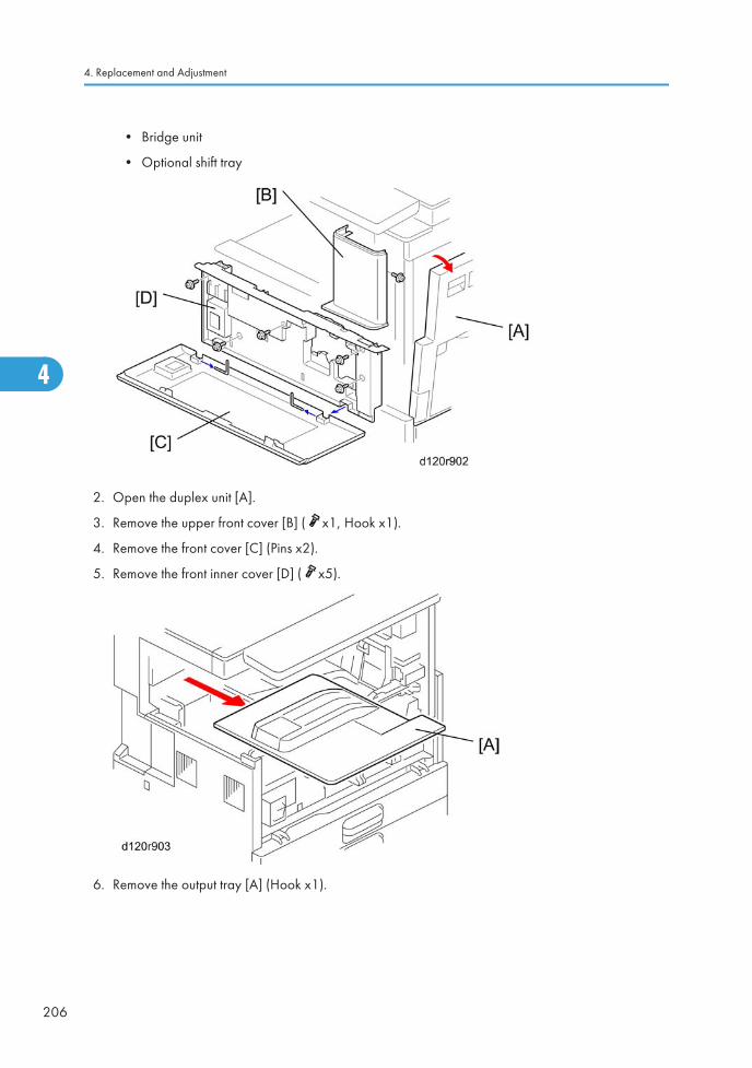
• Bridge unit
• Optional shift tray
2. Open the duplex unit [A].
3. Remove the upper front cover [B] ( x1, Hook x1).
4. Remove the front cover [C] (Pins x2).
5. Remove the front inner cover [D] ( x5).
6. Remove the output tray [A] (Hook x1).
4. Replacement and Adjustment
206
4

7. Remove the toner supply unit [A].
8. Remove the laser unit [B] ( x2, x2, x1).
Polygon Mirror Motor
1. Remove the laser unit ( p.205 "Laser Unit").
2. Remove the heat sink [A] ( x4).
3. Replace the polygon mirror motor [B] ( x4, x1).
• When you install the new polygon mirror motor, do not touch the surface of the mirror with barehands.
Laser Unit
207
4

LD Unit
1. Remove the laser unit. ( p.205 "Laser Unit")
2. Replace the LD unit [A] ( x2, x1).
• Do not touch any variable resistors on the LD unit.
• Do not loose the screws [B].
Laser Synchronization Detector
1. Remove the laser unit. ( p.205 "Laser Unit")
4. Replacement and Adjustment
208
4

2. Remove the heat sink [A] ( x4).
3. Remove the laser unit cover [B] ( x3).
4. Remove the bracket [C] ( x1).
5. Replace the laser synchronization detector [D] ( x1).
Laser Unit
209
4

Photoconductor Unit (PCU)
• Turn off the main power switch and disconnect the power cord before you start any of theprocedures in this section. To prevent toner leakage, never loosen or remove the screws shown inthe illustration below.
PCU Removal
1. Open the right cover [A] and front cover [B].
2. Push the latch [C] and replace the PCU [D] ( x 1).
4. Replacement and Adjustment
210
4

• Do not touch the drum surface with bare hands.
Pick-off Pawls
1. Remove the PCU. ( p.210 "PCU Removal")
2. Hold the pawl [A] by its sides, pull it down and slowly twist it away from the PCU.
OPC Drum
1. Remove the PCU. ( p.210 "PCU Removal")
Photoconductor Unit (PCU)
211
4

2. Remove the front cover [A] ( x2).
3. Remove the rear cover [B] ( x3, Coupling x1).
4. Remove the top part [C] ( x1).
5. Remove the bottom part [D].
6. Replace the drum [E] (White clip x1 [F]).
4. Replacement and Adjustment
212
4

Charge Roller, Cleaning Roller
1. Remove:
• PCU ( p.210 "PCU Removal")
• OPC drum ( p.211 "OPC Drum")
2. Remove the front stud [A].
3. Remove the rear shoulder screw [B] ( x1).
4. Release the front and rear springs [C].
5. Remove the roller assembly [D] (Springs x2, Arms x2, Rollers x2)
6. Replace the charge roller [E].
7. Replace the cleaning roller [F].
Re-installation: Charge Roller
• Put the end of the charge roller with the wide bevel [G] at the front of the PCU.
• The ends of the cleaning roller [F] are the same (put either end at the front).
• Make sure that the front stud of the roller assembly is put in the correct position.
• Install the front stud before you tighten the rear shoulder screw. Make sure that the head of the studis put in the correct position.
Photoconductor Unit (PCU)
213
4

Cleaning Blade
1. Remove:
• PCU ( p.210 "PCU Removal")
• OPC drum ( p.211 "OPC Drum")
• Charge roller and cleaning roller ( p.213 "Charge Roller, Cleaning Roller ")
2. Replace the cleaning blade [A] ( x2)
Reinstallation: Cleaning Blade
• To prevent damage to the new cleaning blade and OPC drum, apply some toner to the edge of thenew blade [B].
• Install the new blade. Remove some toner from the edge of the old blade with your finger, andapply it evenly along the full length of the new blade.
Developer
1. Spread the vinyl sheet provided with the developer kit on a flat surface.
2. Separate the top and bottom parts of the PCU. ( p.211 "OPC Drum")
3. Set the bottom on the vinyl sheet.
4. Replacement and Adjustment
214
4

4. Remove the front screw [A] ( x1)
5. Remove the rear screws [B] ( x2).
6. Release the front tab [C].
7. Release the rear tab [D].
8. Separate the top [E] and bottom [F] of the development unit.
9. Turn the gears [G] to remove the developer from the bottom half.
Photoconductor Unit (PCU)
215
4

10. Remove the development roller [H] from the development unit.
• At reinstallation, make sure that the mylar is positioned as shown.
11. Turn the development roller gear [I] to remove toner from around the development roller.
12. Assemble the development unit.
• Dispose of the used developer according to the local laws and regulations regarding thedisposal of such items.
4. Replacement and Adjustment
216
4

13. Open the developer pack [J]
14. While turning the black gear [K], slowly move the pack left and right and pour half of thedeveloper over the auger [L].
15. Continue to rotate the black gear until the developer is level.
While continuing to turn the black gear, slowly move the pack left and right and pour the remaining halfof the developer over the augur until the developer is level.
• Be careful. Do not spill developer on the gears or sponges.
• If you accidentally spill developer on the gears or sponges, remove it with a magnet or the tip of amagnetized screwdriver.
PCU Reassembly
Reassemble the PCU in this order:
Photoconductor Unit (PCU)
217
4

1. Attach the front frame pawls and front and rear [A].
2. Set the rear cover and front cover [B].
• Never touch the lever [C] until after the top screw has been fastened.
3. Tighten the three screws and coupling [D].
• Never press down on the top of the PCU when you reattach the rear or front cover.
4. Tighten the lower screw [E].
• Always install the lower screw first to maintain the correct gap between the rollers.
5. Tighten the top screw [F].
• Lift and lower the lever [C] to make sure that the shutter opens fully and operates smoothly.
6. Attach the side screw [G].
4. Replacement and Adjustment
218
4
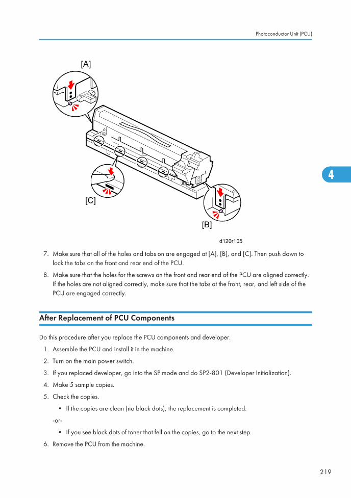
7. Make sure that all of the holes and tabs on are engaged at [A], [B], and [C]. Then push down tolock the tabs on the front and rear end of the PCU.
8. Make sure that the holes for the screws on the front and rear end of the PCU are aligned correctly.If the holes are not aligned correctly, make sure that the tabs at the front, rear, and left side of thePCU are engaged correctly.
After Replacement of PCU Components
Do this procedure after you replace the PCU components and developer.
1. Assemble the PCU and install it in the machine.
2. Turn on the main power switch.
3. If you replaced developer, go into the SP mode and do SP2-801 (Developer Initialization).
4. Make 5 sample copies.
5. Check the copies.
• If the copies are clean (no black dots), the replacement is completed.
-or-
• If you see black dots of toner that fell on the copies, go to the next step.
6. Remove the PCU from the machine.
Photoconductor Unit (PCU)
219
4

7. Lightly tap the top of the PCU [A] with a screwdriver at 8 locations. These locations must be atequal intervals. Tap 2 or 3 times at each location, to make the toner fall into the developmentsection.
8. Install the PCU in the machine.
9. Turn on the main power switch, and close the front door. After the machine turns the developmentroller for 10 seconds, go to the next step.
10. Open and close the door two more times. The total rotation time is 30 seconds.
11. If you replaced PCU components:
• If A4/81/2" x11" paper is installed, make 4 copies or prints.
• If A3/11" x 17" paper is installed, make 2 copies or prints.
• To make solid black prints, use SP2-109 No.8.
• This step is not necessary if only the developer was replaced.
4. Replacement and Adjustment
220
4

Transfer Unit
• Turn off the main power switch and disconnect the power cord before you start any of theprocedures in this section.
Transfer Roller Unit
1. Open the right cover [A].
2. Replace the transfer roller unit [B] (Hook x1).
• Do not touch the transfer roller surface.
Image Density Sensor
1. Open the right cover.
2. Remove transfer roller unit. ( p.221 "Transfer Roller Unit")
Transfer Unit
221
4

3. Displace the mylar [A] of the transfer roller guide.
4. Replace the image density sensor [B] ( x1).
5. After you install a new sensor, initialize the new sensor with SP2-935.
4. Replacement and Adjustment
222
4

Fusing/Exit
• Turn off the main power switch and disconnect the power cord before you start any of theprocedures in this section.
Fusing Unit
• Allow time for the unit to cool before doing the following procedure.
1. Open the duplex unit.
2. Remove the fusing unit [A] ( x2).
Thermistors
1. Remove the fusing unit. ( p.223 "Fusing Unit")
Fusing/Exit
223
4

2. Remove the plates [A] ( x1 each).
3. Replace the thermistors [B] ( x1).
Thermostats
1. Remove the fusing unit. ( p.223 "Fusing Unit")
2. Remove the fusing upper cover [A] ([B]: Screw with spring washer x2, [C]: Stud screw x2).
4. Replacement and Adjustment
224
4

3. Remove the pressure spring [A].
4. Remove the pressure spring [B].
5. Remove the ground wire [C] ( x1).
6. Remove the hot roller stripper bracket [D] ( x4).
7. Remove the thermostat cover [A] (Tap x 2).
8. Remove the plate [B] ( x 2 , spring washers).
Fusing/Exit
225
4

9. Remove the thermostat holders [A] x2 ( x3 each).
10. Replace the thermostats [B] x4.
Hot Roller and Fusing Lamps
1. Remove the fusing unit. ( p.223 "Fusing Unit")
2. Remove these parts: ( p.224 "Thermostats").
• Fusing upper cover
• Pressure springs
• Hot roller stripper bracket
4. Replacement and Adjustment
226
4

3. Replace the fusing lamps ( x4) and hot roller assembly [A].
• Do not touch the surface of the fusing lamp with bare hands.
4. Replace the hot roller [A] (C-rings x2, Gear x1, Bushings x2).
Reinstallation
1. At the rear (gear-side), attach the C-ring so that the opening [A] is 90 degrees from the D-cutsections [B] of the fusing roller.
Fusing/Exit
227
4

2. Apply enough grease at [C] so the metal surface is not visible.
3. The grease should be visible after reattaching the bushing [D].
• Before you install the new hot roller, peel off 3 cm (1 inch) from both ends of the protective sheeton the new roller.
• Do not touch the surface of the rollers.
• When reinstalling the fusing lamp, secure the front screws first.
• Be careful not to damage the surface of the hot roller.
Pressure Roller/Cleaning Roller
1. Remove the fusing lamp and hot roller assembly. ( p.226 "Hot Roller and Fusing Lamps")
2. Replace the pressure roller [A] ( x1, Bushings x2, Spring x1).
3. Replace the cleaning roller [B].
4. Replacement and Adjustment
228
4
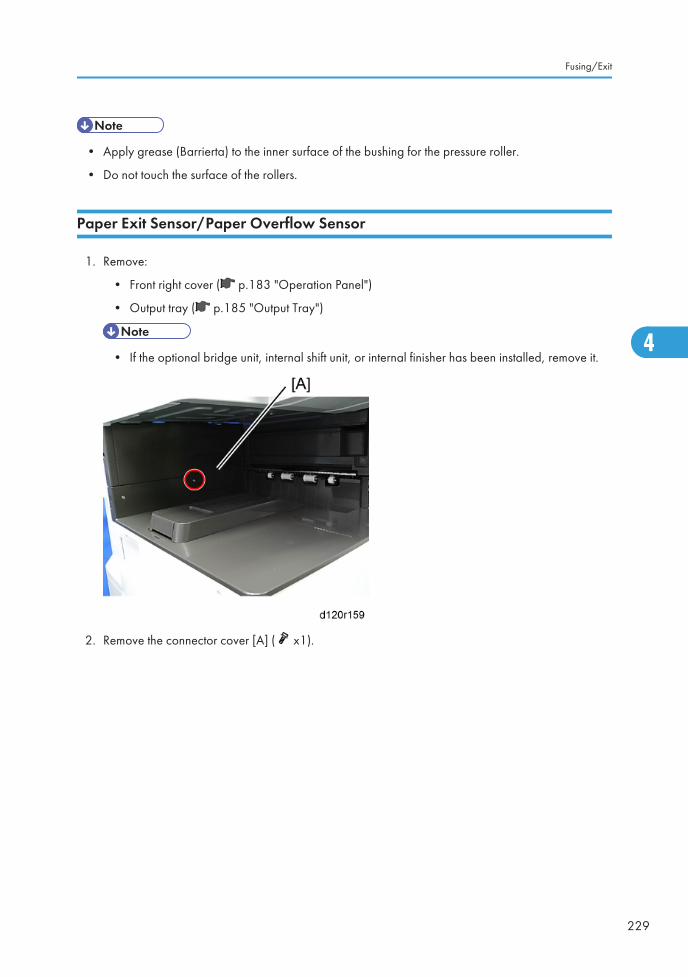
• Apply grease (Barrierta) to the inner surface of the bushing for the pressure roller.
• Do not touch the surface of the rollers.
Paper Exit Sensor/Paper Overflow Sensor
1. Remove:
• Front right cover ( p.183 "Operation Panel")
• Output tray ( p.185 "Output Tray")
• If the optional bridge unit, internal shift unit, or internal finisher has been installed, remove it.
2. Remove the connector cover [A] ( x1).
Fusing/Exit
229
4

3. Remove the inner rear cover [A] ( x2).
4. Remove the paper exit cover. ( p.184 "Paper Exit Cover")
5. Remove the paper exit lower cover [A].
4. Replacement and Adjustment
230
4

6. Remove the sensor cover [A].
7. Replace the exit sensor [A] ( x1).
8. Replace the overflow sensor [B] ( x1).
Fusing/Exit
231
4

Paper Feed
• Turn off the main power switch and disconnect the power cord before you start any of theprocedures in this section.
Paper Feed Unit
1. Remove:
• Paper feed clutch ( p.238 "Paper Feed Clutch")
• Duplex unit ( p.245 "Duplex Unit")
2. Pull out the 1st and 2nd paper trays.
3. Remove the paper guide plate [A] (tab x 2 each)
4. Remove the harness cover [A] ( x 1 each).
4. Replacement and Adjustment
232
4
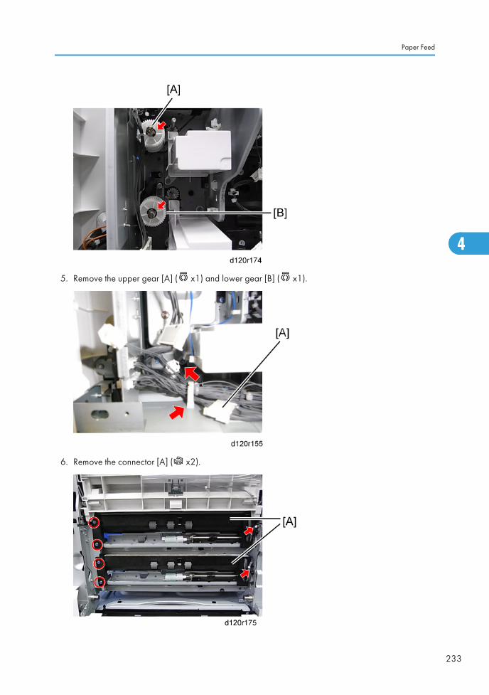
5. Remove the upper gear [A] ( x1) and lower gear [B] ( x1).
6. Remove the connector [A] ( x2).
Paper Feed
233
4

7. Remove the paper feed unit [A] ( x 2, x 1 each).
Pull the left side of the paper feed unit, and slide it to the left.
Separation Roller, Feed Roller
Tray 1 and Tray 2
1. Pull out the 1st and 2nd paper trays.
2. Remove the duplex unit ( p.245 "Duplex Unit")
3. Remove the paper guide plate [A] (tab x 2 each).
4. Replace the separation roller [A] ( x 1).
4. Replacement and Adjustment
234
4

5. Remove the roller holder [A] ( x 1).
6. Replace the feed roller [B].
7. Replace the pick-up roller [C].
Paper Tray Lift Motors
1. Remove:
• Upper rear cover ( p.181 "Upper Rear Cover").
• Lower rear cover ( p.181 "Lower Rear Cover").
2. Pull out the 1st and 2nd paper trays.
Paper Feed
235
4

3. Replace the paper lift motors [A] ( x2 each, x1, x3 each).
Registration Clutch
1. Remove the upper rear cover ( p.181 "Upper Rear Cover")
2. Replace the registration clutch [A] ( x1, x1).
Transport Clutch
1. Remove:
4. Replacement and Adjustment
236
4

• Upper rear cover ( p.181 "Upper Rear Cover")
• Lower rear cover ( p.181 "Lower Rear Cover")
2. Remove the bracket [A] ( x3, x 3, x 2).
Paper Feed
237
4

3. Replace the upper transport clutch [A] ( x 1, x 1).
4. Replace the lower transport clutch [B] ( x 1, x 1).
Paper Feed Clutch
1. Remove the transport clutch. ( p.236 "Transport Clutch")
4. Replacement and Adjustment
238
4

2. Replace the upper feed clutch [A] ( x1, x1, x1).
3. Replace the lower feed clutch [B] ( x1, x1, x1).
Paper Size Sensors
1. Remove:
• Upper rear cover ( p.181 "Upper Rear Cover")
• Lower rear cover ( p.181 "Lower Rear Cover")
2. Pull out the 1st and 2nd paper trays.
Paper Feed
239
4

3. Remove the tray 1 paper size sensor cover [A] ( x 2) and/or, tray 2 paper size sensor cover [B]( x 2).
4. Replace the tray 1 paper size sensor [A] ( x 1, Pawls x4) and/or tray 2 paper size sensor [B]( x 1, Pawls x4).
Registration Sensor
1. Remove the duplex unit ( p.245 "Duplex Unit").
4. Replacement and Adjustment
240
4

1. Displace the mylar [A] of the transfer roller guide.
2. Remove the image density sensor [B] ( x1).
3. Open the transfer roller guide [C].
4. Remove the paper guide plate [A] ( x2).
Paper Feed
241
4

5. Remove the registration sensor bracket [A] ( x1, x1).
6. Replace the registration sensor [A] (hook x4).
Vertical Transport, Paper Overflow, Paper End and Paper Feed Sensor
1. Remove the paper feed unit ( p.232 "Paper Feed Unit")
4. Replacement and Adjustment
242
4

2. Replace the paper overflow sensor [A].
3. Remove the paper end feeler [B] (hook, x 1).
4. Replace the paper end sensor [C] (hook, x 1)
5. Remove the vertical transport sensor bracket [D] ( x 1, x 1).
6. Replace the vertical transport sensor [E] ( x 1, hook).
7. Remove the paper feed sensor bracket [F] ( x 1).
8. Replace the paper feed sensor [G]( x 1, hook).
Paper Feed
243
4

Dust Collection Box
1. Open the front door.
2. Remove the dust collection box [A]( x1).
3. Tap the dust collection box above a sheet of paper, to remove the paper dust.
4. Use a dry cloth to clean the inside of the dust collection box.
4. Replacement and Adjustment
244
4

Duplex Unit
Duplex Unit
1. Remove:
• Upper rear cover( p.181 "Upper Rear Cover")
• Lower rear cover ( p.181 "Lower Rear Cover")
• Right rear cover ( p.181 "Right Rear Cover")
2. Remove or disconnect two connectors [A].
3. Remove or disconnect two ground cables [B] ( x 2).
Duplex Unit
245
4

4. Remove the lower right cover [A] (spring x 2, tab x 2).
5. Remove the guide plate (tab x 2).
6. Open the duplex unit.
4. Replacement and Adjustment
246
4

7. Release the front arm [A] and rear arm [B] ( x 1).
8. Slide the duplex unit to the front side, and then remove it.
Duplex Entrance Sensor
1. Remove the duplex unit ( p.245 "Duplex Unit").
Duplex Unit
247
4

2. Lift up the duplex guide plate [A] first when reinstalling the duplex outer guide plate.
3. Remove the duplex outer guide plate [A] ( x 1).
4. Replacement and Adjustment
248
4

4. Replace the duplex entrance sensor [A] (hook).
Duplex Exit Sensor
1. Remove the duplex unit ( p.245 "Duplex Unit").
2. Remove the duplex exit sensor assembly [A] ( x 3, x 1).
Duplex Unit
249
4

3. Replace the duplex exit sensor [A] (hook).
Duplex Motor/Bypass Motor
1. Remove the duplex unit ( p.245 "Duplex Unit").
2. Remove the duplex inner cover [A] ( x 2).
4. Replacement and Adjustment
250
4

3. Remove the duplex entrance motor with the bracket [A] ( x 5, x 5, x 2).
4. Replace the separate the duplex entrance motor [A] from the bracket ( x 2).
Duplex Unit
251
4

5. Replace the by-pass motor [A] ( x 2).
By-pass Tray Unit
1. Remove the duplex inner cover. ( p.250 "Duplex Motor/Bypass Motor ")
4. Replacement and Adjustment
252
4

2. Disconnect the harness [A].
3. Open the by-pass tray unit [A].
4. Replace the by-pass tray unit ( x 2, hook [B]).
• Use a flat-head screw driver or similar tool to push the hook [B] down.
By-pass Paper Length Sensor
1. Open the by-pass tray unit.
Duplex Unit
253
4

2. Remove the by-pass tray right cover [A] ( x 2).
3. Replace the by-pass paper length sensor [A] ( x 1).
By-Pass Paper Size Sensor
1. Remove the by-pass tray unit ( p.252 "By-pass Tray Unit").
2. Remove the by-pass tray cover [A] (hook x 1).
4. Replacement and Adjustment
254
4
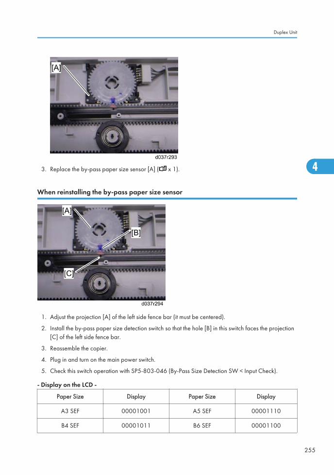
3. Replace the by-pass paper size sensor [A] ( x 1).
When reinstalling the by-pass paper size sensor
1. Adjust the projection [A] of the left side fence bar (it must be centered).
2. Install the by-pass paper size detection switch so that the hole [B] in this switch faces the projection[C] of the left side fence bar.
3. Reassemble the copier.
4. Plug in and turn on the main power switch.
5. Check this switch operation with SP5-803-046 (By-Pass Size Detection SW < Input Check).
- Display on the LCD -
Paper Size Display Paper Size Display
A3 SEF 00001001 A5 SEF 00001110
B4 SEF 00001011 B6 SEF 00001100
Duplex Unit
255
4

A4 SEF 00000011 A6 SEF 00001101
B5 SEF 00000111 Smaller A6 SEF 00001101
By-pass Paper End Sensor
1. Remove the by-pass tray unit. ( p.252 "By-pass Tray Unit")
2. Replace the by-pass paper end sensor [A] ( x 1, hook).
Reinstalling the By-pass Paper End Sensor
• Reinstall the right hook first and then the left hook using a flat-head screw driver or similar tool.
By-pass Feed Roller
1. Remove the by-pass tray unit. ( p.252 "By-pass Tray Unit")
2. Replace the by-pass feed roller [A] (hook).
4. Replacement and Adjustment
256
4

By-pass Tray HP Sensor
1. Remove the duplex unit. ( p.245 "Duplex Unit")
2. Remove the duplex inner front cover [A] ( x 2).
3. Replace the by-pass HP sensor [A] ( x 1, hook x4).
Duplex Unit
257
4

PCBs and Other Items
• Turn off the main power switch and disconnect the power cord before you start any of theprocedures in this section.
Controller Board
• If you intend to replace the NVRAM, upload its contents to an SD card with SP5-824 before youremove NVRAM and replace it with a new one. Never remove the NVRAM until after you haveuploaded its contents.
Before replacing the controller board in the model without HDD
When you replace the controller board in a model without a HDD, address book data can be copiedfrom an old controller board to a new controller board using an SD card.
Copy the address book data to an SD card from the flash ROM on the controller board withSP5-846-051 if possible.
Replacement Procedure
1. Remove the controller cover. ( p.179 "Controller Cover")
2. Remove the FCU faceplate [A] ( x3).
4. Replacement and Adjustment
258
4

3. Remove the controller board unit [A] ( x3).
• Before touching the controller board, always touch a metal surface to discharge any staticthat has accumulated on your hands.
4. Remove the controller board [A] ( x5).
• Before removing the controller board, remove the HDD and option interface boards.
PCBs and Other Items
259
4

5. Remove the upper brace [A].
6. Remove the lower brace [B]
7. Remove the NVRAM [C] from the old board and install it on the new board.
8. If you have replaced the controller board, set the DIP switches on the new controller board to thesame settings as the old board.
After installing the controller board
1. For a model without a HDD, do SP5-846-052 to copy back the address book to the flash ROM onthe controller board from the SD card to which you have already copied the address book data ifpossible.
2. If the customer is using the data encryption feature, the encryption key must be restored.
3. Turn the main power switch off and on.
NVRAM
The following data stored in the NVRAM will not be saved to the SD card when you perform anNVRAM data upload (SP5-824).
• Total counter value
• C/O, P/O counter values
• Duplex, A3/DLT/Over 420mm, Stapler, and Scanner counter values
• Engine SP data
Therefore, whenever you perform an NVRAM upload/download, make sure to print out the SP Data Listbefore you perform SP5-801-001 (Memory Clear: All Clear) or SP5-801-002 (Memory Clear:Engine).
4. Replacement and Adjustment
260
4

1. Do SP5-990 001 to print the SMC report.
2. Stop all SDK applications if the VM card is installed.
3. Turn off the main power switch.
4. Remove the controller cover ( x1). ( p.179 "Controller Cover")
5. Remove the VM card from SD card slot 2 if it is installed.
6. Put the SD card in SD card slot 2.
7. Turn on the main power switch.
8. Do SP5-824.
9. Touch "Execute" to start to upload the NVRAM data.
10. Turn off the main power switch and remove the SD card.
11. Remove the controller board. ( p.258 "Controller Board")
12. Remove the NVRAM and replace it with the new chip. ( p.258 "Controller Board")
13. Install the controller board.
14. Put the SD card with the NVRAM data in SD card slot 2.
15. Turn on the main power switch.
16. Do SP5-801 to initialize the new NVRAM.
17. To download the NVRAM data from the SD card in slot 2, do SP5-825.
18. Touch "Execute" to start to download the NVRAM data.
19. Turn off the main power switch and remove the SD card.
20. Turn on the main power switch.
21. Do SP5-990-001 to print another SMC report.
22. Compare this new SMC report with the report you printed in Step 1. If any of the SP settings aredifferent, input the SP settings of the first report.
23. Do SP5-907 and input the brand and model name of the machine for Windows Plug & Playcapability.
BCU Board
1. Remove:
• Upper rear cover ( p.181 "Upper Rear Cover")
• Lower rear cover ( p.181 "Lower Rear Cover")
PCBs and Other Items
261
4

2. Replace the BCU board [A] ( x All, x6).
3. Remove the NVRAM [B] from the old board and install it on the new board.
4. Set the DIP switches on the new BCU board to the same settings as the old board.
• Make sure the NVRAM is correctly installed on the BCU. Insert the NVRAM in the NVRAMslot with the "half-moon" pointing [C] to the left side.
When installing the new BCU
1. Remove the NVRAM from the old BCU.
2. Install the NVRAM on the new BCU after you replace the BCU.
3. Reassemble the machine.
4. Turn on the main power switch.
5. "SC995-01" occurs.
6. Enter the serial number with SP5-811-004.
7. Turn the main power switch off and on.
• Make sure you print out the SMC reports ("SP Mode Data" and "Logging Data") before youreplace the NVRAM.
4. Replacement and Adjustment
262
4

• Keep NVRAM away from any objects that can cause static electricity. Static electricity can damageNVRAM data.
Power Pack
1. Remove:
• Upper rear cover ( p.181 "Upper Rear Cover")
• Lower rear cover ( p.181 "Lower Rear Cover")
2. Replace the power pack [A] ( x 5, x2, Standoff x2).
Main Motor
1. Remove the upper rear cover ( p.181 "Upper Rear Cover")
PCBs and Other Items
263
4

2. Replace the main motor [A] ( x 4, x 1).
SDB
1. Remove:
• Optional finishers except internal finisher if it has been installed.
• Left cover ( p.179 "Left Cover")
2. Remove the SDB assembly [A] ( x4, x2).
4. Replacement and Adjustment
264
4

3. Replace the SDB [A] ( x2).
PSU
1. Remove:
• Optional finishers except internal finisher if it has been installed.
• SDB ( p.264 "SDB")
2. Remove the transformer [A] ( x1, x1) (For the 230 V machine only).
PCBs and Other Items
265
4

3. Replace the PSU [A] ( x all, x5, Standoff x1).
IPU
1. Remove:
• Upper rear cover. ( p.181 "Upper Rear Cover")
• Lower rear cover. ( p.181 "Lower Rear Cover")
• Controller board unit ( p.258 "Controller Board")
2. Remove the FFC cover [A] ( x3).
4. Replacement and Adjustment
266
4

3. Remove the IPU with bracket [A] ( x5, x All, FFC x2).
4. Replace the IPU [A] ( x7).
HDD
1. Before you replace the HDD:
• Stop all SDK applications, and then remove it from the machine if the VM card is installed.
PCBs and Other Items
267
4

• Insert an SD card in SD card slot 2 (lower slot).
• Go into the SP mode.
• Do SP5-846 51 to upload the address book data to the SD card.
• If the HDD is damaged, you may not be able to retrieve this data from the HDD.
2. Remove the controller board. ( p.258 "Controller Board")
3. Remove the connecting board unit [A] ( x2, x 2, x 1).
4. Replacement and Adjustment
268
4

4. Remove the HDD unit [A] ( x 3).
5. Remove the old HDD [A] from its bracket ( x4, x2).
6. Install the new HDD unit.
7. Turn the main power switch off and on.
PCBs and Other Items
269
4

8. Format the HDD with SP5-832-1.
9. Do SP5-853 to copy the preset stamp data from the firmware to the hard disk.
10. Do SP5-846-52 to restore the address book data to the HDD.
After HDD Replacement:
• Never remove a used HDD unit from the work site (even if it is suspected of being damaged)without the consent of the client.
• The HDD must remain with the customer for disposal or safe keeping.
• The HDD may contain proprietary or classified (Confidential, Secret) information. Specifically, theHDD contains document server documents and data stored in temporary files created automaticallyduring copy job sorting and jam recovery. Such data is stored on the HDD in a special format, so itcannot normally be read but it can possibly be recovered with illegal methods.
4. Replacement and Adjustment
270
4

Copy Adjustments: Printing/ScanningYou must do these adjustment(s) after replacing any of the following parts:
• Scanner Wire
• Lens Block/SBU Assembly
• Scanner Drive Motor
• Polygon Mirror Motor
• Paper Side Fence
• Memory All Clear
For more details about accessing SP modes, see Service Tables.
Printing
• Make sure the paper is installed correctly in each paper tray before you start these adjustments.
• Use the Trimming Area Pattern (SP2-109-001, No.14) to print the test pattern for the followingprocedures.
• Set SP 2-109-001 to 0 again after completing these printing adjustments.
Registration - Leading Edge/Side-to-Side
Copy Adjustments: Printing/Scanning
271
4

A: Leading Edge Registration (3 ± 2 mm)
B: Side-to-side Registration (2 ± 1.5 mm)
1. Check the leading edge registration [A] for each paper feed station, and adjust them usingSP1-001.
Tray SP mode
Tray: Plain SP1-001-002
Tray: Thick 1 SP1-001-003
Tray: Thick 2 SP1-001-004
By-pass: Plain SP1-001-007
By-pass: Thick 1 SP1-001-008
By-pass: Thick 2 SP1-001-009
Duplex: Plain SP1-001-013
Duplex: Thick 1 SP1-001-014
2. Check the side-to-side registration [B] for each paper feed station, and adjust them using SP1-002.
Tray SP mode
By-pass SP1-002-001
Tray 1 SP1-002-002
Tray 2 SP1-002-003
Tray 3 (Optional PFU tray 1 or LCT) SP1-002-004
Tray 4 (Optional PFU tray 2) SP1-002-005
Duplex (side 1) SP1-002-006
Blank Margin
• If the leading edge/side-to-side registration cannot be adjusted within the specifications, adjust theleading/left side edge blank margin.
4. Replacement and Adjustment
272
4

A: Trailing Edge Blank Margin (3 ± 2 mm, duplex: 2 ± 2 mm)
B: Right Edge Blank Margin (2 + 2.5/-1.5 mm)
C: Leading Edge Blank Margin (-3 ± 2 mm)
D: Left Edge Blank Margin (-3 ±2 mm, duplex: -2 ± 1.5 mm)
1. Check the trailing edge [A], right edge [B], leading edge [C], left edge [D] blank margins, andadjust them using the following SP modes.
SP mode
Leading Edge SP2-103-001
Trailing Edge SP2-103-002
Left Edge SP2-103-003
Right Edge SP2-103-004
Duplex: Trailing Edge:
L Size: PlainSP2-103-005
Duplex: Trailing Edge:
M Size: PlainSP2-103-006
Copy Adjustments: Printing/Scanning
273
4

SP mode
Duplex: Trailing Edge:
S Size: PlainSP2-103-007
Duplex: Left Edge
PlainSP2-103-008
Duplex: Right Edge:
PlainSP2-103-009
Duplex: Trailing Edge:
L Size: ThickSP2-103-010
Duplex: Trailing Edge:
M Size: ThickSP2-103-011
Duplex: Trailing Edge:
S Size: ThickSP2-103-012
Duplex: Left Edge
ThickSP2-103-013
Duplex: Right Edge:
ThickSP2-103-014
• L Size: Paper Length is 297.1 mm or more
• M Size: Paper Length is 216.1 to 297 mm
• S Size: Paper Length is 216 mm or less.
Main Scan Magnification
1. Use SP2-109-001, no.5 (Grid Pattern) to print the single-dot grid pattern.
2. Check the magnification, and adjust the magnification using SP2-102 (Magnification AdjustmentMain Scan) if necessary. The specification is ± 1%.
Parallelogram Image Adjustment
Do the following procedure if a parallelogram is printed while adjusting the printing registration or theprinting margin using a trimming area pattern.
4. Replacement and Adjustment
274
4

• The following procedure should be done after adjusting the side-to-side registration for each papertray station.
1. Check whether the trimming area pattern (SP2-109, No.14) is printed as a parallelogram, asshown. If it is, do the following.
2. Remove the laser unit [A] ( p.205 "Laser Unit").
3. Remove the bracket [B] ( x2).
4. Install the adjusting cam [C] (P/N: A2309003).
5. Secure the adjustment bracket [D] (P/N: A1849501) using the screw which was used for bracket[B]. However, do not tighten the screws at this time.
6. Adjusts the laser unit position by turning the adjusting cam. (Refer to the above illustration for therelationship between the image and the cam rotation direction).
7. Tighten the adjustment bracket.
8. Print the trimming area pattern to check the image. If it is still unsatisfactory, repeat steps 4 to 8.
Scanning
• Before doing the following scanner adjustments, perform or check the printing registration/side-to-side adjustment and the blank margin adjustment.
Copy Adjustments: Printing/Scanning
275
4

• Use an S5S test chart to perform the following adjustments.
Registration: Platen Mode
A: Leading Edge Registration
B: Side-to-side Registration
1. Place the test chart on the exposure glass and make a copy from one of the feed stations.
2. Check the leading edge and side-to-side registration, and adjust them using the following SPmodes if necessary.
SP mode
Leading Edge SP4-010
Side-to-side SP4-011
Magnification
• Use an S5S test chart to do the following adjustment.
4. Replacement and Adjustment
276
4

1. Place the test chart on the exposure glass and make a copy from one of the feed stations.
2. Check the magnification ratio. Use SP4-008 (Scanner Sub Scan Magnification) to adjust ifnecessary. Specification: ±0.9%.
ADF Image Adjustment
Registration
A: Leading Edge Registration
B: Side-to-side Registration
Copy Adjustments: Printing/Scanning
277
4
• Make a temporary test chart as shown above using A3/DLT paper.
1. Place the temporary test chart on the ADF and make a copy from one of the feed stations.
2. Check the registration, and adjust using the following SP modes if necessary.
SP mode
Side-to Side: Front SP6-006-001
Side-to Side: Rear SP6-006-002
Leading Edge SP6-006-003
Buckle: Duplex front SP6-006-005
Buckle: Duplex rear SP6-006-006
Rear Edge Erase SP6-006-007
Sub Scan Magnification
• Make a temporary test chart as shown above using A3/DLT paper.
1. Place the temporary test chart on the ADF and make a copy from one of the feed stations.
2. Check the magnification, and adjust using the following SP modes if necessary. The specification is±1%.
SP mode
Sub scan magnification SP6-017-001
Touch Screen Calibration
After clearing the memory, or if the touch panel detection function is not working correctly, follow thisprocedure to calibrate the touch screen.
• Do not attempt to use items [2] to [9] on the Self-Diagnostic Menu. These items are for design useonly.
1. Press , input 1993 at the ten-key pad, and then press 5 times to open the Self-Diagnosticsmenu.
4. Replacement and Adjustment
278
4

2. On the touch screen press "Touch Screen Adjust" (or press on the ten-key pad).
3. Use a pointed (not sharp!) tool to press the mark at the upper left of the screen ( ).
4. Press the mark at the lower right of the screen ( ) after it appears.
5. Touch a few spots on the touch panel to confirm that the marker (+) appears exactly where thescreen is touched.
• If the + mark does not appear where the screen is touched, press Cancel and repeat fromStep 2.
6. When you are finished, press [#] OK on the screen (or press on the ten-key pad).
7. Touch [#] Exit on the screen to close the Self-Diagnostic menu and save the calibration settings.
Copy Adjustments: Printing/Scanning
279
4

4. Replacement and Adjustment
280
4
5. System Maintenance
Service Program Mode
• Make sure that the data-in LED ( ) is not on before you go into the SP mode. This LED indicatesthat some data is coming to the machine. When the LED is on, wait for the copier to process thedata.
SP Tables
See "Appendices" for the following information:
• System SP Tables
Enabling and Disabling Service Program Mode
• The Service Program Mode is for use by service representatives only. If this mode is used byanyone other than service representatives for any reason, data might be deleted or settings mightbe changed. In such case, product quality cannot be guaranteed any more.
Entering SP Mode
For details, ask your supervisor.
Exiting SP Mode
• Press "Exit" on the LCD twice to return to the copy window.
Types of SP Modes
• System SP: SP modes related to the engine functions
• Printer SP: SP modes related to the controller functions
• Scanner SP: SP modes related to the scanner functions
• Fax SP: SP modes related to the fax functions
281
5

Select one of the Service Program modes (System, Printer, Scanner, or Fax) from the touch panel asshown in the diagram below after you access the SP mode. This section explains the functions of theSystem/Printer/Scanner SP modes. Refer to the Fax service manual for the Fax SP modes.
SP Mode Button Summary
Here is a short summary of the touch-panel buttons.
1 Opens all SP groups and sublevels.
2 Closes all open groups and sublevels and restores the initial SP mode display.
5. System Maintenance
282
5

3Opens the copy window (copy mode) so you can make test copies. Press SP Mode(highlighted) in the copy window to return to the SP mode screen,
4Enter the SP code directly with the number keys if you know the SP number. Then press .(The required SP Mode number will be highlighted when pressing . If not, just press therequired SP Mode number.)
5Press two times to leave the SP mode and return to the copy window to resume normaloperation.
6 Press any Class 1 number to open a list of Class 2 SP modes.
7 Press to scroll the show to the previous or next group.
8 Press to scroll to the previous or next display in segments the size of the screen display (page).
9 Press to scroll the show the previous or next line (line by line).
10 Press to move the highlight on the left to the previous or next selection in the list.
Switching Between SP Mode and Copy Mode for Test Printing
1. In the SP mode, select the test print. Then press "Copy Window".
2. Use the copy window (copier mode), to select the appropriate settings (paper size, etc.) for the testprint.
3. Press Start to start the test print.
4. Press SP Mode (highlighted) to return to the SP mode screen and repeat from step 1.
Selecting the Program Number
Program numbers have two or three levels.
1. Refer to the Service Tables to find the SP that you want to adjust before you begin.
2. Press the Group number on the left side SP Mode window that contains the SP that you want toadjust.
3. Use the scrolling buttons in the center of the SP mode window to show the SP number that you wantto open. Then press that number to expand the list.
4. Use the center touch-panel buttons to scroll to the number and title of the item that you want to setand press it. The small entry box on the right activates and shows the below default or the currentsettings.
Service Program Mode
283
5

• Refer to the Service Tables for the range of allowed settings.
5. Do this procedure to enter a setting:
• Press to toggle between plus and minus and use the keypad to enter the appropriatenumber. The number you enter writes over the previous setting.
• Press to enter the setting. (The value is not registered if you enter a number that is out ofrange.)
• Press "Yes" when you are prompted to complete the selection.
6. If you need to perform a test print, press Copy Window to open the copy window and select thesettings for the test print. Press Start and then press SP Mode (highlighted) in the copy window toreturn to the SP mode display.
7. Press Exit two times to return to the copy window when you are finished.
Exiting Service Mode
Press the Exit key on the touch-panel.
Service Mode Lock/Unlock
At locations where the machine contains sensitive data, the customer engineer cannot operate themachine until the Administrator turns the service mode lock off. This function makes sure that work on themachine is always done with the permission of the Administrator.
1. If you cannot go into the SP mode, ask the Administrator to log in with the User Tool and then set"Service Mode Lock" to OFF after he or she logs in:
User Tools > System Settings > Administrator Tools > Service Mode Lock > OFF
• This unlocks the machine and lets you get access to all the SP codes.
5. System Maintenance
284
5

• The CE can service the machine and turn the machine power switch off and on. It is notnecessary to ask the Administrator to log in again each time the main power switch is turnedon.
2. Go into the SP mode and set SP5-169 to "1" if you must use the printer bit switches.
3. After machine servicing is completed:
• Change SP5-169 from "1" to "0".
• Turn the machine power switch off and on. Tell the administrator that you have completedservicing the machine.
• The Administrator will then set the "Service Mode Lock" to ON.
Remarks
The following symbols are used in the SP mode tables.
FA: Factory setting
(Data may be adjusted from the default setting at the factory. Refer to the factory setting sheets enclosed.You can find it under the jammed paper removal decal.)
DFU: Design/Factory Use only
Do not touch these SP modes in the field.
A sharp (#) to the right hand side of the mode number column means that the main power switch mustbe turned off and on to effect the setting change.
An asterisk (*) to the right hand side of the mode number column means that this mode is stored in theNVRAM. If you do a RAM clear, this SP mode will be reset to the default value. "ENG" and "CTL" showwhich NVRAM contains the data.
• ENG: NVRAM on the BCU board
• CTL: NVRAM on the controller board
The settings of each SP mode are explained in the right-hand column of the SP table in the followingway.
[Adjustable range / Default setting / Step] Alphanumeric
• If "Alphanumeric" is written to the right of the bracket as shown above, the setting of the SP modeshows on the screen using alphanumeric characters instead of only numbers. However, the settingsin the bracket in the SP mode table are explained by using only the numbers.
SSP: This denotes a "Special Service Program" mode setting.
Service Program Mode
285
5

Firmware UpdateTo update the firmware for this machine, you must have the new version of the firmware downloadedonto an SD (Secure Digital) Card. The SD Card is inserted into SD Card Slot 2 on the left rear side of thecontroller box.
Type of Firmware
Type of firmware Function Location of firmware Message shown
Engine Printer engine control BCU Flash ROM Engine
System/CopyApplication
Operating system Flash ROM on thecontroller board
System/Copy
Printer ApplicationFeature application Flash ROM on the
controller boardPrinter
Scanner ApplicationFeature application Flash ROM on the
controller boardScanner
Fax ApplicationFeature application Flash ROM on the
controller boardFax
NIBNetwork Interface Flash ROM on the
controller boardNetwork Support
Operation Panel Panel control Operation Panel Lcdc.
Fax FCU Fax control FCU GWFCU3.5-1(WW)
Remote FaxFax control Flash ROM on the
controller boardRemote Fax
Language
Language firmware
Two languages can beselected from 16languages.
Operation Panel Language 1
Language 2
WebDocBoxDocument serverapplication
Flash ROM on thecontroller board
Web Uapl
WebSysWeb Serviceapplication
Flash ROM on thecontroller board
Web Support
5. System Maintenance
286
5

Type of firmware Function Location of firmware Message shown
PDF PDF direct printing PDF
PSPage descriptionlanguage (PostScript3)
PS3 SD card PS
RPCS
Page descriptionlanguage (RPCS forXPS driver dataprocess)
Flash ROM on thecontroller board
RPCS
MediaPrint:JPEG/IFFMediaPrint control Flash ROM on the
controller boardMediaPrint:JPEG/TIFF
Netfile ApplicationFeature application Flash ROM on the
controller boardNetworkDocBox
Summary fontSummary fonts Flash ROM on the
controller boardFONT
PCL FontPCL fonts Flash ROM on the
controller boardFONT1
PS 3 fontPost Script 3 fonts Flash ROM on the
controller boardFONT2
ARDF ARDF control ARDF ADF
Finisher Finisher control Finisher Finisher
Java VM SDK application Java VM SD card SDK
Data OverwriteSecurity
Security application Flash ROM on thecontroller board
HDD Format Option
Before You Begin
An SD card is a precision device. Always observe the following precautions when you handle SD cards:
• Always switch the machine off before you insert an SD card. Never insert the SD card into the slotwith the power on.
• Do not remove the SD card from the service slot after the power has been switched on.
• Never switch the machine off while the firmware is downloading from the SD card.
Firmware Update
287
5

• Keep SD cards in a safe location where they are not exposed to high temperature, high humidity,or exposure to direct sunlight.
• Always handle SD cards with care. Do not bend or scratch them. Do not let the SD card getexposed to shock or vibration.
• Make sure that the write protection of an SD card is unlocked when you download an applicationto it. If not, downloading fails and a download error (e.g. Error Code 44) occurs during a firmwareupgrade.
Keep the following points in mind when you use the firmware update software:
• "Upload" means to send data from the machine to the SD card. "Download" means to send datafrom the SD card to the machine.
• To select an item on the LCD, touch the appropriate button on the soft touch-screen of the LCD, or,press the appropriate number key on the 10-key pad of the operation panel. For example, when"Exit (0)" shows on the screen you can touch the Exit button on the screen, or, press the buttonon the operation panel of the copier.
• Make sure that the machine is disconnected from the network to prevent a print job for arrivingwhile the firmware update is in progress before you start the firmware update procedure.
Updating Firmware
Preparation
• If the SD card is blank, make a "romdata" folder on the SD card.
• If the card already contains a “romdata” folder, copy the “firmware” to the folder.
Updating Procedure
1. Turn off the main power switch.
2. Remove the controller cover ( x 1).
3. Insert the SD card into SD Card Slot 2. Make sure the label on the SD card faces the front side ofthe machine.
4. Slowly push the SD card into the slot so it locks in place. You will hear it click. Make sure the SDcard locks in place.
• To remove the SD, push it in to unlock the spring lock. Then release it so it pops out of the slot.
5. Disconnect the network cable from the copier if the machine is connected to a network.
6. Switch the main power switch on. After about 45 seconds, the initial version update screenappears on the LCD in English.
5. System Maintenance
288
5

7. On the screen, touch the button or press the corresponding number key on the operation panel toselect the item in the menu that you want to update.
ROM/NEW What it means
ROM:Tells you the number of the module and name of the version currentlyinstalled. The first line is the module number, the second line the versionname.
NEW:Tells you the number of the module and name version on the SD card. Thefirst line is the module number, the second line the version name.
• Controller, engine and operation panel firmware cannot be updated at the same time. It isrecommended to update firmware modules one by one.
8. Touch "UpDate (#)" (or ) to start the update.
• The progress bar does not show for the operation panel firmware after you touch "OpPanel".The power on key flashes on and off at 0.5 s intervals when the LCDC firmware is updating.The power key flashes on and off at three seconds intervals when the update is finished.
9. The "Update is Done" message appears on the operation panel after completing the updating. Themessage differs depending on the firmware that has been updated.
10. Switch the copier main power switch off when you see the "Update is Done" message or follow theprocedure that is displayed on the operation panel.
11. Press in the SD card to release it. Then remove it from the slot.
12. Switch the copier on for normal operation.
Error Messages
An error message shows in the first line if an error occurs during the download.
The error code consists of the letter "E" and a number. The example above shows error "E24" displayed.For details, refer to the Error Message Table. ( p.294 "Handling Firmware Update Errors" in thissection)
Firmware Update Error
If a firmware update error occurs, this means the update was cancelled during the update because themodule selected for update was not on the SD card.
Firmware Update
289
5

Recovery after Power Loss
If the ROM update is interrupted as a result of accidental loss of power while the firmware is updating,then the correct operation of the machine cannot be guaranteed after the machine is switched on again.If the ROM update does not complete successfully for any reason, then in order to ensure the correctoperation of the machine, the ROM update error will continue to show until the ROM is updatedsuccessfully.
In this case, insert the card again and switch on the machine to continue the firmware downloadautomatically from the card without the menu display.
Updating the LCDC for the Operation Panel
Do the following procedure to update the LCDC (LCD Control Board).
1. Turn off the main power switch.
2. Remove the SD slot cover ( x 1).
3. Insert the SD card into SD Card Slot 2.
4. Switch the copier main switch on.
5. The initial screen opens in English after about 45 seconds.
6. Touch "Ope Panel.xx".
7. "xx" differs depending on the destination.
8. Touch "UpDate(#) or ( ) to start the update.
9. Downloading starts after about 9 seconds.
5. System Maintenance
290
5

10. The operation panel goes off and the main power on key flashes in red at 0.5 s intervals when thedata is downloading. The same key starts flashing in green at 1 s intervals when the update isfinished.
11. Switch the copier main power switch off and remove the SD card. Then switch the copier on.
Update Procedure for App2Me Provider
Follow this procedure to update App2Me if a new version is available.
1. Push the [User/Tools] key on the operation panel.
2. If an administrator setting is registered for the machine, Step 3 and Step 4 are required. Otherwise,skip to step 5.
3. Push [Login/Logout] on the operation panel.
4. Login with the administrator user name and password.
5. Touch "Extended Feature Settings" twice on the LCD.
6. Touch each of the applications until the status changes to "Stop".
7. Turn off the main power switch, and then remove the SD Card which contains Java-VM.
8. Prepare the newer App2Me Provider zip file from the Firmware Download Center, and then unzipthe zip file. (The folder name is "337051920".)
9. Copy the App2Me Provider folder into the specified path for the SD Card which contains Java-VM.The path is:
"SD_Card Drive\ sdk\dsdk\dist\337051920"
10. Turn the SD card label face to the front of the machine, and then push it slowly into Slot 2 (lowerslot) until you hear a click.
Firmware Update
291
5

11. Turn on the main power switch.
12. Press [User Tools] on the operation panel.
13. Touch the "Extended Feature Settings" button twice.
14. Touch the "Extended Feature Info" tab on the LCD.
15. Touch the "App2Me" line.
16. Set the setting of the "Auto Start" to "On".
17. Touch the "Exit" button.
18. Exit the [User Tools/Counter] settings.
• App2Me and all other running applications on the SD Card which contains Java-VM must be shutdown before removing the SD Card contains Java-VM in order to update the firmware, back upNVRAM, install the browser unit, or execute application move or undo with SP5-873.
• After the SD Card which contains Java-VM is re-inserted, App2Me (and any other Java-VMapplications used by the customer) must be switched on after the machine is switched on.
Browser Unit Update Procedure
1. Remove the controller cover [A] ( x1).
5. System Maintenance
292
5

2. Turn the SD-card label face of the browser unit to the front of the machine. Then push it slowly intoslot 1 or slot 2 [A] until you hear a click.
3. Plug in and turn on the main power switch.
4. Push the "User Tools" key.
• If an administrator setting is registered for the machine, step 5 and 6 are required. Otherwise,skip to the step 7
5. Push the "Login/ Logout" key.
6. Login with the administrator user name and password.
7. Touch "Extended Feature Settings" twice on the LCD.
8. Touch "Uninstall" on the LCD.
9. Touch the "Browser" line
10. Confirmation message appears on the LCD.
11. Touch "Yes" to proceed.
12. Reconfirmation message appears on the LCD.
13. Touch "Yes" to uninstall the browser unit.
14. You will see "Uninstalling the extended feature... Please wait.", and then "Completed".
15. Touch "Exit" to go back to the setting screen.
16. Exit "User/Tools" setting, and then turn off the main power switch.
17. Remove the SD card of the browser unit from the SD card slot.
18. Overwrite the updated program in the "sdk" folder of the browser unit application with PC.
19. Do the "Installation Procedure" to install the browser unit.
Firmware Update
293
5

Handling Firmware Update Errors
An error message shows in the first line if an error occurs during a download. The error code consists ofthe letter "E" and a number ("E20", for example).
Error Message Table
Code Meaning Solution
20 Cannot map logical address Make sure the SD card is inserted correctly.
21 Cannot access memory HDD connection incorrect or replace hard disks.
22Cannot decompress compresseddata
Incorrect ROM data on the SD card, or data iscorrupted.
23Error occurred when ROMupdate program started
Controller program abnormal. If the second attemptfails, replace controller board.
24 SD card access errorMake sure SD card inserted correctly, or use anotherSD card.
30No HDD available for stampdata download
HDD connection incorrect or replace hard disks.
31Data incorrect for continuousdownload
Insert the SD card with the remaining data required forthe download, the re-start the procedure.
32Data incorrect after downloadinterrupted
Execute the recovery procedure for the intendedmodule download, then repeat the installationprocedure.
33 Incorrect SD card versionIncorrect ROM data on the SD card, or data iscorrupted.
34Module mismatch - Correctmodule is not on the SD card)
SD update data is incorrect. Acquire the correct data(Japan, Overseas, OEM, etc.) then install again.
35Module mismatch – Module onSD card is not for this machine
SD update data is incorrect. The data on the SD card isfor another machine. Acquire correct update data theninstall again.
36Cannot write module – Causeother than E34, E35
SD update data is incorrect. The data on the SD card isfor another machine. Acquire correct update data theninstall again.
5. System Maintenance
294
5
40 Engine module download failedReplace the update data for the module on the SD cardand try again, or replace the BCU board.
42Operation panel moduledownload failed
Replace the update data for the module on the SD cardand try again, or replace the LCDC.
43Stamp data module downloadfailed
Replace the update data for the module on the SD cardand try again, or replace the hard disks.
44Controller module downloadfailed
Replace the update data for the module on the SD cardand tray again, or replace controller board.
50Electronic confirmation checkfailed
SD update data is incorrect. The data on the SD card isfor another machine. Acquire correct update data theninstall again.
Firmware Update
295
5
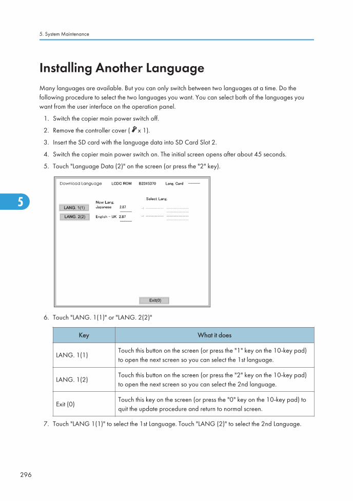
Installing Another LanguageMany languages are available. But you can only switch between two languages at a time. Do thefollowing procedure to select the two languages you want. You can select both of the languages youwant from the user interface on the operation panel.
1. Switch the copier main power switch off.
2. Remove the controller cover ( x 1).
3. Insert the SD card with the language data into SD Card Slot 2.
4. Switch the copier main power switch on. The initial screen opens after about 45 seconds.
5. Touch "Language Data (2)" on the screen (or press the "2" key).
6. Touch "LANG. 1(1)" or "LANG. 2(2)"
Key What it does
LANG. 1(1)Touch this button on the screen (or press the "1" key on the 10-key pad)to open the next screen so you can select the 1st language.
LANG. 1(2)Touch this button on the screen (or press the "2" key on the 10-key pad)to open the next screen so you can select the 2nd language.
Exit (0)Touch this key on the screen (or press the "0" key on the 10-key pad) toquit the update procedure and return to normal screen.
7. Touch "LANG 1(1)" to select the 1st Language. Touch "LANG (2)" to select the 2nd Language.
5. System Maintenance
296
5

8. Touch the appropriate button on the screen (or press the number on the 10-keypad) to select alanguage as the 1st (or 2nd) language.
• If a language is already selected, it will show in reverse.
• Touching "Exit (0)" returns you to the previous screen.
9. If you do not see the language that you want to select, touch " (7)" or " (9)" on the screen (orpress the "7" or "9" key) to show more choices.
The Download Screen opens after you select a language.
The 1st or 2nd language selected for updating shows.
The following show to right of the selection:
• 1. The first column shows the language currently selected.
• 2. The 2nd column shows the language selected to replace that language.
The example below shows that the download will replace "Japanese" with "Italian" as the 1stlanguage.
Installing Another Language
297
5

10. Touch "Update(#)" on the screen (or press ) to start the download.
Another screen with a progress bar does not show when the language is downloading.
The following occur at the time the language is downloading:
• The operation panel switches off.
• The LED on the power on key flashes rapidly.
11. After the message of installation completed has shown on the LCD, switch the copier main powerswitch off. Then remove the SD card from the slot.
12. Switch the copier main power switch on to resume normal operation.
5. System Maintenance
298
5

Reboot/System Setting Reset
Software Reset
You can reboot the software with one of the following two procedures:
1. Turn the main power switch off and on.
2. Press and hold down and together for over 10 seconds. When the machine beeps once,release both buttons. After “Now loading. Please wait” shows for a few seconds, the copy windowwill open. The machine is ready for normal operation.
System Settings and Copy Setting Reset
System Setting Reset
The system settings in the UP mode can be reset to their defaults. Use the following procedure.
1. Press User Tools/Counter .
2. Hold down and then press System Settings.
• You must press first.
3. Press yes when the message prompts you to confirm that you want to reset the system settings.
4. Press exit when the message tells you that the settings have been reset.
Copier Setting Reset
Use the following procedure to reset the copy settings in the UP mode to their defaults.
1. Press User Tools/Counter .
2. Hold down and then press Copier/Document Server Settings.
Reboot/System Setting Reset
299
5
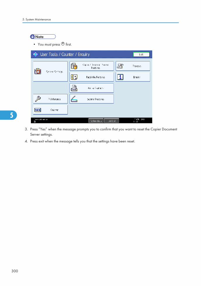
• You must press first.
3. Press “Yes” when the message prompts you to confirm that you want to reset the Copier DocumentServer settings.
4. Press exit when the message tells you that the settings have been reset.
5. System Maintenance
300
5

NVRAM Data Upload/Download
Uploading Content of NVRAM to an SD card
Do the following procedure to upload SP code settings from NVRAM to an SD card.
• This data should always be uploaded to an SD card before the NVRAM is replaced.
• Make sure that the write protection of an SD card is unlocked
1. Do SP5-990-001 (SMC Print) before you switch the machine off. You will need a record of theNVRAM settings if the upload fails.
2. Switch the copier main power switch off.
3. Remove the controller cover [A] ( x 1).
4. Insert the SD card [A] into SD slot 2. Then switch the copier on.
5. Execute SP5-824-001 (NVRAM Data Upload) and then press the “Execute” key.
NVRAM Data Upload/Download
301
5

6. The following files are coped to an NVRAM folder on the SD card when the upload procedure isfinished. The file is saved to the path and the following filename:
NVRAM\<serial number>.NV
Here is an example with Serial Number “K5000017114”:
NVRAM\K5000017114.NV
7. In order to prevent an error during the download, be sure to mark the SD card that holds theuploaded data with the number of the machine from which the data was uploaded.
• You can upload NVRAM data from more than one machine to the same SD card.
Downloading an SD Card to NVRAM
Do the following procedure to download SP data from an SD card to the NVRAM in the machine.
• The NVRAM data down load may fail if the SD card with the NVRAM data is damaged, or if theconnection between the controller and BCU is defective.
• Do the download procedure again if the download fails.
• Do the following procedure if the second attempt fails:
• Enter the NVRAM data manually using the SMC print you created before uploading the NVRAMdata.
1. Switch the copier main power switch off.
2. Remove the controller cover ( x 1).
3. Insert the SD card with the NVRAM data into SD slot 2.
4. Switch the copier main power switch on.
5. Do SP5-825-001 (NVRAM Data Download) and press the “Execute” key.
• The serial number of the file on the SD card must match the serial number of the machine forthe NVRAM data to download successfully. The download fails if the serial numbers do notmatch.
This procedure does not download the following data to the NVRAM:
• Total Count
• C/O, P/O Count
5. System Maintenance
302
5

Address Book Upload/Download
Information List
The following information is possible to be uploaded and downloaded.
Information
• Registration No.
• User Code
• Protection Code
• Fax Destination
• Fax Option
• Group Name
• Key Display
• Select Title
• Folder
• Local Authentication
• Folder Authentication
• Account ACL
• New Document Initial ACL
• LDAP Authentication
Download
1. Prepare a formatted SD card.
2. Make sure that the write-protection on the SD card is off.
3. Turn off the main power switch.
4. Remove the controller cover [A] ( x 1).
Address Book Upload/Download
303
5

5. Install the SD card [A] into the SD card slot 2 (for service use).
6. Turn on the main power switch.
7. Enter the SP mode.
8. Do SP5-846-051 (Backup All Addr Book).
9. Exit the SP mode, and then turn off the main power switch.
10. Remove the SD card from the SD card slot 2.
11. Install the controller cover.
• If the capacity of SD card is not enough to store the local user information, an error messageis displayed.
• Carefully handle the SD card, which contains user information. Do not take it back to yourlocation.
Upload
1. Turn off the main power switch.
2. Remove the controller cover ( x 1).
3. Install the SD card, which has already been uploaded, into the SD card slot 2.
4. Turn on the main power switch.
5. Enter the SP mode.
6. Do SP5-846-052 (Restore All Addr Book).
7. Exit the SP mode, and then turn off the main power switch.
8. Remove the SD card form the SD card slot 2.
9. Install the controller cover.
5. System Maintenance
304
5

• The counter in the user code information is initialized after uploading.
• The information of an administrator and supervisor cannot be downloaded nor uploaded.
• If there is no data of address book information in the SD card, an error message is displayed.
Address Book Upload/Download
305
5

LED and DIP Switches
LEDs
Controller
Number NormalController Software
DownloadError
LED 1 Off Blinking Off
LED 2 Blinking Blinking Lit or Off
BCU
Number NormalController Software
DownloadError
LED 1 Lit Lit Off or Blinking
LED 2 Blinking LitLit (except downloading) orOff
DIP Switches
Controller
SW2
Number OFF ON
1 Boot from SD card Default: Boot from Flash ROM
2 to 4 Default: OFF DFU ---
BCU
SW102
5. System Maintenance
306
5

DestinationBit
1 2 3 4
Japan OFF OFF OFF OFF
NA ON OFF OFF OFF
EU/ASIA OFF ON OFF OFF
LED and DIP Switches
307
5

Using the Debug Log
Overview
This machine provides a Save Debug Log feature that allows the Customer Engineer to save and retrieveerror information for analysis.
Every time an error occurs, debug information is recorded in volatile memory. But this information is lostwhen the machine is switched off and on.
To capture this debug information, the Save Debug Log feature provides two main features:
• Switching on the debug feature so error information is saved directly to the HDD for later retrieval.
• Copying the error information from the HDD to an SD card.
Do the following procedure below to set up the machine so the error information is saved automaticallyto the HDD when a user has problems with the machine. Then ask the user to reproduce the problem.
Switching ON and Setting UP Save Debug Log
The debug information cannot be saved until the “Save Debug Log” function has been switched on anda target has been selected.
1. Enter the SP mode and switch the Save Debug Log feature on.
• Enter the SP mode.
• Touch “System SP”.
• On the LCD panel, open SP5857.
2. Under “5857 Save Debug Log”, touch “1 On/Off”.
3. On the control panel keypad, press “1”. Then press . This switches the Save Debug Log featureon.
5. System Maintenance
308
5

• The default setting is “0” (OFF). This feature must be switched on in order for the debuginformation to be saved.
4. Select the target destination where the debug information will be saved. Under “5857 Save DebugLog”, touch “2 Target”, enter “2” with the operation panel key to select the hard disk as the targetdestination. Then press .
• Select “3 SD Card” to save the debug information directly to the SD card if it is inserted in theservice slot.
5. Now touch “5858” and specify the events that you want to record in the debug log. SP5-858(Debug Save When) provides the following items for selection.
1 Engine SC ErrorSaves data when an engine-related SC code isgenerated.
2 Controller SC ErrorSaves debug data when a controller-related SC Codeis generated.
3 Any SC ErrorSaves data only for the SC code that you specify byentering code number.
4 Jam Saves data for jams.
• More than one event can be selected.
Example 1: To Select Items 1, 2, 4
Touch the appropriate items(s). Press “ON” for each selection. This example shows “Engine SCError” selected.
Using the Debug Log
309
5

Example 2: To Specify an SC Code
Touch “3 Any SC Error”, enter the 3-digit SC code number with the control panel number keys.Then press . This example shows an entry for SC670.
• For details about SC code numbers, please refer to the SC tables in Section 4.“Troubleshooting”.
6. Select one or more memory modules for reading and recording debug information. Touch “5859”.
Under “5859” press the necessary key item for the module that you want to record.
Enter the appropriate 4-digit number. Then press .
• Refer to the two tables below for the 4-digit numbers to enter for each key.
The example below shows “Key 1” with “2222” entered.
5. System Maintenance
310
5

The following keys can be set with the corresponding numbers. (The initials in parentheses indicatethe names of the modules.)
4-Digit Entries for Keys 1 to 10
Key No. Copy Printer Scanner Web
1 2222 (SCS)
2 14000 (SRM)
3 256 (IMH)
4 1000 (ECS)
5 1025 (MCS)
6 4848 (COPY) 4400 (GPS) 5375 (Scan) 5682 (NFA)
7 2224 (BCU) 4500 (PDL) 5682 (NFA)6600
(WebDB)
8 4600 (GPS-PM) 3000 (UCS) 3300 (PTS)
9 2000 (NCS) 2000 (NCS)6666
(WebSys)
10 2224 (BCU) 4126 (DCS) 2000 (NCS)
• The default settings for Keys 1 to 10 are all zero (“0”).
Key to Acronyms
Acronym Meaning Acronym Meaning
ECS Engine Control Service NFA Net File Application
GPS GW Print Service PDL Printer Design Language
Using the Debug Log
311
5

Acronym Meaning Acronym Meaning
GSP-PMGW Print Service – PrintModule
PTS Print Server
IMH Image Memory Handler SCS System Control Service
MCS Memory Control Service SRMSystem ResourceManagement
NCS Network Control Service WebDBWeb Document Box(Document Server)
7. The machine is now set to record the debugging information automatically on the HDD (the targetselected with SP5-857-002) for the events that you selected with SP5-858 and the memorymodules selected with SP5-859.
Please keep the following important points in mind when you do this setting:
• Note that the number entries for Keys 1 to 5 are the same for the Copy, Printer, Scanner, and Webmemory modules.
• The initial settings are all zero.
• These settings remain in effect until you change them. Be sure to check all the settings, especiallythe settings for Keys 6 to 10. To switch off a key setting, enter a zero for that key.
• You can select any number of keys from 1 to 10 (or all) by entering the corresponding 4-digitnumbers from the table.
• You cannot mix settings for the groups (COPY, PRINTER, etc.) for 006 to 010. For example, if youwant to create a PRINTER debug log you must select the settings from the 9 available selections forthe “PRINTER” column only.
• One area of the disk is reserved to store the debug log. The size of this area is limited to 4 MB.
Retrieving the Debug Log from the HDD
Retrieve the debug log by copying it from the hard disk to an SD card.
1. Insert the SD card into slot 2 (service slot) of the copier.
2. Enter the SP mode and execute SP5-857-009 (Copy HDD to SD Card (Latest 4 MB)) to write thedebugging data to the SD card.
3. Use a card reader to copy the file and send it for analysis to your local Ricoh representative byemail. You can also send the SD card by regular mail if you want.
5. System Maintenance
312
5

Recording Errors Manually
SC errors and jams only are recorded to the debug log automatically. Please instruct the user to do thefollowing immediately after occurrence to save the debug data for any other errors that occur while thecustomer engineer is not on site. Such problems also include a controller or panel freeze.
• You must previously switch on the Save Debug Feature (SP5-857-001) and select the hard disk asthe save destination (SP5-857-002) if you want to use this feature.
1. Press (Clear Modes).on the operation panel when the error occurs.
2. On the control panel, enter “01”. Then hold down for at least 3 seconds until the machinebeeps and then release it. This saves the debug log to the hard disk for later retrieval with an SDcard by the service representatives.
3. Switch the machine off and on to resume operation.
The debug information for the error is saved on the hard disk. This lets the service representativeretrieve it on their next visit by copying it from the HDD to an SD card.
Debug Log Codes
SP5-857-015 Copy SD Card-to-SD Card: Any Desired Key
This SP copies the log on an SD card (the file that contains the information written directly from sharedmemory) to a log specified by key number. The copy operation is executed in the log directory of the SDcard inserted in the same slot. (This function does not copy from one slot to another.) Each SD card canhold up to 4 MB of file data. Unique file names are created for the data during the copy operation toprevent overwriting files of the same name. This means that log data from more than one machine canbe copied onto the same SD card. This command does not execute if there is no log on the HDD for thename of the specified key.
SP5-857-016 Create a File on HDD to Store a Log
This SP creates a 32 MB file to store a log on the HDD. However, this is not a completely empty file. Thecreated file will hold the number “2225” as the SCS key number and other non-volatile information.Even if this SP is not executed, a file is created on the HDD when the first log is stored on the HDD (ittakes some time to complete this operation). This creates the possibility that the machine may beswitched off and on before the log can be created completely. If you execute this SP to create the logfile beforehand, this will greatly reduce the amount of time required to acquire the log information andsave onto the HDD. With the file already created on the HDD for the log file, the data only needs to berecorded. A new log file does not need to be created. To create a new log file, do SP5-857-011 todelete the debug log data from the HDD. Then do SP5-857-016.
Using the Debug Log
313
5

SP5-857-017 Create a File on SD Card to Store a Log
This SP creates a 4 MB file to store a log on an SD card. However, this is not a completely empty file.The created file will hold the number “2225” as the SCS key number and other non-volatile information.Even if this SP is not executed, a file is created on the SD card when the first log is stored on the SD card(it takes some time to complete this operation). This creates the possibility that the machine may beswitched off and on before the log can be created completely. If you execute this SP to create the logfile beforehand, this will greatly reduce the amount of time required to acquire the log information andsave onto the SD card. With the file already created on the SD card for the log file, the data only needsto be recorded; a new log file does not require creation. To create a new log file, do SP5-857-012 todelete the debug log data from the SD card. Then do SP5-857-017.
5. System Maintenance
314
5

User ToolsThe user program (UP) mode can be accessed by users and operators, and by sales and service staff.UP mode is used to input the copier’s default settings. The user can reset the default settings at any time.(See ‘System Setting and Copy Setting Reset’.)
UP Mode Initial Screen: User Tools/Counter Display
To enter the UP mode, press User Tools/Counter.
System Settings
User Tools
315
5
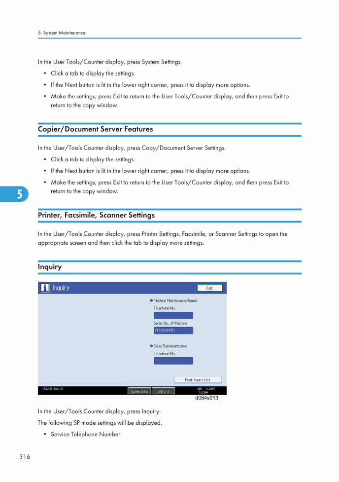
In the User Tools/Counter display, press System Settings.
• Click a tab to display the settings.
• If the Next button is lit in the lower right corner, press it to display more options.
• Make the settings, press Exit to return to the User Tools/Counter display, and then press Exit toreturn to the copy window.
Copier/Document Server Features
In the User/Tools Counter display, press Copy/Document Server Settings.
• Click a tab to display the settings.
• If the Next button is lit in the lower right corner, press it to display more options.
• Make the settings, press Exit to return to the User Tools/Counter display, and then press Exit toreturn to the copy window.
Printer, Facsimile, Scanner Settings
In the User/Tools Counter display, press Printer Settings, Facsimile, or Scanner Settings to open theappropriate screen and then click the tab to display more settings.
Inquiry
In the User/Tools Counter display, press Inquiry.
The following SP mode settings will be displayed.
• Service Telephone Number
5. System Maintenance
316
5

• Serial Number of Machine
• Sales Representative Telephone No.
Counter
In the User/Tools Counter display, press Counter.
View the settings, press Exit to return to the User Tools/Counter display, and then press Exit to return tothe copy window.
User Tools
317
5

5. System Maintenance
318
5

6. Troubleshooting
Service Call ConditionsFor "Service Call Conditions" information, see "Appendices".
319
6

Self-Diagnostic Mode
Self-Diagnostic Mode at Power On
As soon as the main machine is powered on, the controller waits for the initial settings of the copy engineto take effect and then starts an independent self-diagnostic test program. The self-diagnostic test followsthe path of the flow chart shown below and checks the CPU, memory, HDD, and so on. An SC code isdisplayed in the touch panel if the self-diagnostic program detects any malfunction or abnormalcondition.
6. Troubleshooting
320
6

Self-Diagnostic Test Flow Chart
Self-Diagnostic Mode
321
6
Detailed Self-Diagnostic Mode
Purpose
In addition to the self-diagnostic test initiated every time the main machine is powered on, you can setthe machine in a more detailed diagnostic mode manually in order to test other components orconditions that are not tested during self-diagnosis after power on.
The following device is required in order to put the machine in the detailed self-diagnosis mode.
Also, the printer/scanner unit and the optional Centronics (IEEE1284) interface must be installed.
Part No. Name
G0219350 Parallel Loopback Connector
Executing Detailed Self-Diagnosis
Follow this procedure to do the detailed self-diagnosis.
1. Switch off the machine, and connect the parallel loopback device to the Centronics I/F port.
2. Hold down the button, press and hold down the button, and then while pressing both keys atthe same time, switch on the machine.
• You will see "Now Loading" on the touch-panel, and then you will see the results of the test.
A report like the one below is printed every time a detailed self-diagnostic test is executed, whethererrors were detected or not.
6. Troubleshooting
322
6
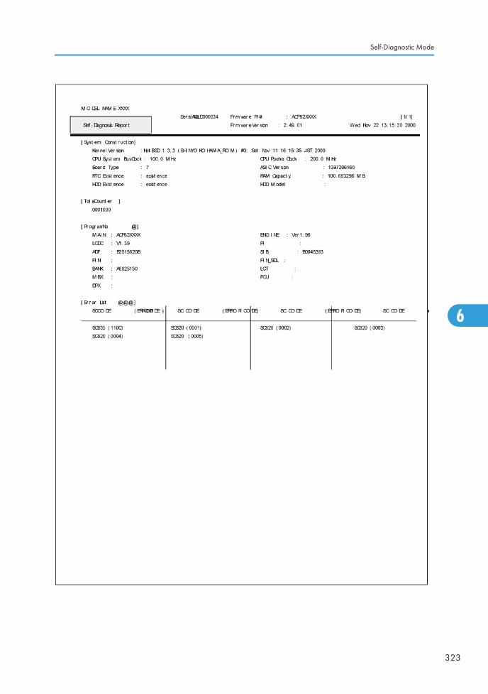
Self-Diagnostic Mode
323
6
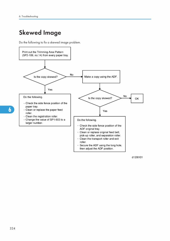
Skewed ImageDo the following to fix a skewed image problem.
6. Troubleshooting
324
6

Image Problems
Skewed, Trapezoid and Parallelogram Images
Skewed Images
• The image's leading and trailing edges are parallel.
• The image's left and right edges are also parallel.
• But, all four sides are not parallel with the paper edge.
Trapezoid Images
• Only the image's trailing edge is not parallel with the paper edge. The other 3 sides are parallel tothe paper's edges.
Image Problems
325
6

6. Troubleshooting
326
6

Parallelogram Images
• Like skewed images, the leading/trailing edges and left/right edges are parallel to each other.But, the leading and trailing edges are not parallel to the paper's edges.
Image Problems
327
6

Checking Images with the Trimming Pattern
6. Troubleshooting
328
6

Correcting the Images
Correcting Skewed Images
1. Test pattern (Trimming Pattern) mode check
Is the image skewed?
No Yes
1. Adjust the side fences. There must be no gap between the fences and thepaper stack.
2. Adjust the paper registration: SP1-002 and 003.
2. Platen mode check
Set an original flush against the left and rear scales and make a copy.
Does the image come out as a parallelogram?
No Yes
Attach the Scanner Holder (a supporter that is normally attached duringshipping)
3. ADF mode check
Feed an original through the ADF.
Is the image skewed?
No Yes
Do the front and rear transportrollers feed the originalstraight?
No Yes
Change the position of the righthinge screw to the longer hole,and make small positionadjustments that are necessary.
Do Procedure A below.
Image Problems
329
6

Procedure complete.
Procedure A
1. Remove the ADF [A], machine rear cover, scanner left cover, and scanner rear cover.
2. Measure the height difference [B] between the hinge bracket [C] and scanner housing [D].
3. If the difference is 0.5 mm or more:
6. Troubleshooting
330
6

Add a spacer (t = 0.5 to 0.8) between the hinge bracket (mainframe) and ADF left hinge, to lift theleft side of the ADF
-or-
Adjust the stepped height difference between the hinge bracket and scanner housing until it iswithin 0 ±0.3 mm.
• This is necessary because skew occurs when the hinge bracket more than 0.3 mm lower thanthe scanner housing.
Correcting Trapezoid Images
Procedure 1: Minor Adjustment of the Fusing Unit Height (front-to-rear)
Image Problems
331
6

1. Print out the Trimming Pattern (SP2-109 No.14).
2. If the image is a pattern A trapezoid:
a) Remove and reinstall the Fusing Unit.
b) Tighten the left fixing screw while you push up the unit's left side (until it stops).
3. If the image is a pattern B trapezoid, do the same for the unit's right side.
4. If the image is still printed out as a trapezoid, do Procedure 2 below.
Procedure 2: Minor Adjustment of the Fusing Unit Position (front-to-rear)
1. Remove and reinstall the fusing unit, then add a washer (t = 0.5 to 1.6) to the front fixing screw.
• This will increase the distance from the mainframe stay.
2. Check the image.
• Still NG: Go to the next step.
• OK: Adjustment Complete.
3. Add more washers (t = 0.5 to 1.6, as above).
• Too many washers can cause wrinkling in the paper.
• Still NG: Go to the next step.
• OK: Adjustment Complete.
4. Remove the fusing unit and all the washers added in steps 1 and 2 above.
5. Then, add washer(s) in the same way for the rear side.
Recommended Washers:
t = 0.5, 07080040Z or 07080040G
t = 0.8, 07080050Z or 07080050G
Correcting Parallelogram Images
For the procedure, see "Parallelogram Image Adjustment".
6. Troubleshooting
332
6

Jam Detection
Paper Jam Display
SP7-507 shows the paper jam history.
• CODE: Indicates the jam code.
• SIZE: Indicates the paper Size Code.
• TOTAL: Indicates the total counter (SP7-502-001).
• DATE: indicates the date when the jam occurred.
Jam Codes and Display Codes
SP7-504 shows how many jams occurred at each location.
Jam CodeSP
Display DescriptionLCD
Display
7-504-003 Tray 1: On Paper is not fed from tray 1. A
7-504-004 Tray 2: On Paper is not fed from tray 2. A
7-504-005 Tray 3: On Paper is not fed from tray 3 (LCT). Y
7-504-006 Tray 4: On Paper is not fed from tray 4. Y
7-504-008 Bypass: On Paper is not fed from the by-pass tray. A
7-504-009 Duplex: On Paper is jammed at the duplex unit. Z
7-504-011 Vertical Trans. 1: OnVertical transport sensor 1 does not detectpaper from tray 1.
A
7-504-012 Vertical Trans .2: OnVertical transport sensor 2 does not detectpaper from tray 2.
A
Jam Detection
333
6

Jam CodeSP
Display DescriptionLCD
Display
7-504-013 Vertical Trans .3: OnVertical transport sensor 1 or relay sensordoes not detect paper from tray 3 (LCT).
Y
7-504-017 Registration: On Registration sensor does not detect paper. A
7-504-020 Paper Exit: On Paper exit sensor does not detect paper. C
7-504-021 Bridge Tray Exit: OnTray exit sensor (bridge unit) does not detectpaper.
D
7-504-022 Bridge Relay: OnRelay sensor (bridge unit) does not detectpaper.
D
7-504-024 Inverter: OnJunction gate jam sensor does not detectpaper.
C
7-504-025 Duplex Exit: On Duplex exit sensor does not detect paper. Z
7-504-027 Duplex Entrance: OnDuplex entrance sensor does not detect paperagain after paper has passed this sensor.
Z
7-504-051 Vertical Trans. 1: Off Vertical transport sensor 1 does not turn off. A
7-504-052 Vertical Trans. 2: Off Vertical transport sensor 2 does not turn off. A
7-504-053Vertical Trans. 3 (PFU):Off
Vertical transport sensor 3 or relay sensor 1does not turn off.
Y
7-504-054Vertical Trans. 4 (PFU):Off
Vertical transport sensor 4 does not turn off. Y
7-504-057 Registration Sensor: Off Registration sensor does not turn off. B
7-504-060 Paper Exit: Off Paper exit sensor does not turn off. C
7-504-061 Bridge Tray Exit: Off Tray exit sensor (bridge unit) does not turn off. D
7-504-062 Bridge Relay: Off Relay sensor (bridge unit) does not turn off. D
7-504-064 Inverter: Off Junction gate jam sensor does not turn off. C
7-504-065 Duplex Exit: Off Duplex exit sensor does not turn off. Z
7-504-067 Duplex Ent: OffDuplex entrance sensor does not turn off afterpaper has passed this sensor.
Z
6. Troubleshooting
334
6

Jam CodeSP
Display DescriptionLCD
Display
7-504-100 Finisher Entrance (D588)Paper does not reach the entrance sensor orstay at the entrance sensor.
R1-R2
7-504-101Finisher Shift Tray Exit(D588)
Paper does not reach the lower tray exitsensor or stay at the lower tray exit sensor.
R1-R2
7-504-102 Finisher Staple (D588)Paper does not reach the staple tray entrancesensor or stay at the staple tray entrancesensor.
R3-R5
7-504-103 Finisher Exit (D588)
Lower tray exit sensor does not detect paperafter the stack feed-out belt has fed paper.
Lower tray exit sensor still detects paper afterthe stack feed-out belt has returned to thehome position.
R3-R5
7-504-105Finisher Tray Lift Motor(D588)
Stack height sensor does not detect paperafter the lower tray has lifted up.
Stack height sensor still detects paper after thelower tray has lifted down.
R1-R2
7-504-106Finisher Jogger Motor(D588)
Jogger fence HP sensor does not turn off afterthe jogger fence has moved from its homeposition.
Jogger fence HP sensor does not turn on afterthe jogger fence has returned to its homeposition.
R3-R5
7-504-107Finisher Shift Motor(D588)
Shift roller HP sensor does not turn off after theshift roller has moved from its home position.
Shift roller HP sensor does not turn on after theshift roller has returned to its home position.
R1-R2
7-504-108Finisher Staple Motor(D588)
Stapler HP sensor does not turn off after thestapler has moved from its home position.
Stapler HP sensor does not turn on after thestapler has returned to its home position.
R3-R5
Jam Detection
335
6
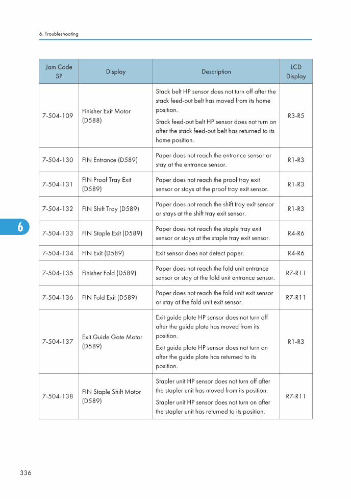
Jam CodeSP
Display DescriptionLCD
Display
7-504-109Finisher Exit Motor(D588)
Stack belt HP sensor does not turn off after thestack feed-out belt has moved from its homeposition.
Stack feed-out belt HP sensor does not turn onafter the stack feed-out belt has returned to itshome position.
R3-R5
7-504-130 FIN Entrance (D589)Paper does not reach the entrance sensor orstay at the entrance sensor.
R1-R3
7-504-131FIN Proof Tray Exit(D589)
Paper does not reach the proof tray exitsensor or stays at the proof tray exit sensor.
R1-R3
7-504-132 FIN Shift Tray (D589)Paper does not reach the shift tray exit sensoror stays at the shift tray exit sensor.
R1-R3
7-504-133 FIN Staple Exit (D589)Paper does not reach the staple tray exitsensor or stays at the staple tray exit sensor.
R4-R6
7-504-134 FIN Exit (D589) Exit sensor does not detect paper. R4-R6
7-504-135 Finisher Fold (D589)Paper does not reach the fold unit entrancesensor or stay at the fold unit entrance sensor.
R7-R11
7-504-136 FIN Fold Exit (D589)Paper does not reach the fold unit exit sensoror stay at the fold unit exit sensor.
R7-R11
7-504-137Exit Guide Gate Motor(D589)
Exit guide plate HP sensor does not turn offafter the guide plate has moved from itsposition.
Exit guide plate HP sensor does not turn onafter the guide plate has returned to itsposition.
R1-R3
7-504-138FIN Staple Shift Motor(D589)
Stapler unit HP sensor does not turn off afterthe stapler unit has moved from its position.
Stapler unit HP sensor does not turn on afterthe stapler unit has returned to its position.
R7-R11
6. Troubleshooting
336
6

Jam CodeSP
Display DescriptionLCD
Display
7-504-139FIN Paper Punch Motor(D589)
Punch encoder sensor does not turn on/offafter the punch drive motor has turned on.
Punch movement HP sensor does not turn on/off after the punch movement motor hasturned on.
Paper position slide HP sensor does not turnon/off after the paper position sensor slidemotor has turned on.
R1-R3
7-504-140FIN Tray Lift Motor(D589)
Shift Tray position sensor does not detectpaper after the shift tray has lifted up.
Shift Tray position sensor still detects paperafter the shift tray has moved down.
R1-R3
7-504-141FIN Jogger Motor(D589)
Jogger fence HP sensor does not turn off afterthe jogger fence has moved from its homeposition.
Jogger fence HP sensor does not turn on afterthe jogger fence has returned to its homeposition.
R7-R11
7-504-142 FIN Shift Motor (D589)
Shift motor HP sensor does not turn off afterthe shift roller has moved from its homeposition.
Shift motor HP sensor does not turn on afterthe shift roller has returned to its homeposition.
R1-R3
7-504-143FIN Fold Plate Motor(D589)
Fold plate HP sensor does not turn off after theshift fold plate has moved from its homeposition.
Fold plate HP sensor does not turn on after thes fold plate has returned to its home position.
R7-R11
7-504-144 FIN Staple Motor (D589)
Corner stapler does not finish stapling after aspecified time.
Booklet stapler does not finish stapling after aspecified time.
R7-R11
Jam Detection
337
6
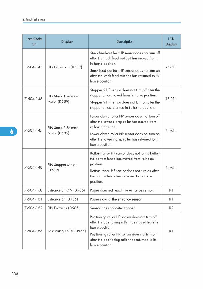
Jam CodeSP
Display DescriptionLCD
Display
7-504-145 FIN Exit Motor (D589)
Stack feed-out belt HP sensor does not turn offafter the stack feed-out belt has moved fromits home position.
Stack feed-out belt HP sensor does not turn onafter the stack feed-out belt has returned to itshome position.
R7-R11
7-504-146FIN Stack 1 ReleaseMotor (D589)
Stopper S HP sensor does not turn off after thestopper S has moved from its home position.
Stopper S HP sensor does not turn on after thestopper S has returned to its home position.
R7-R11
7-504-147FIN Stack 2 ReleaseMotor (D589)
Lower clamp roller HP sensor does not turn offafter the lower clamp roller has moved fromits home position.
Lower clamp roller HP sensor does not turn onafter the lower clamp roller has returned to itshome position.
R7-R11
7-504-148FIN Stopper Motor(D589)
Bottom fence HP sensor does not turn off afterthe bottom fence has moved from its homeposition.
Bottom fence HP sensor does not turn on afterthe bottom fence has returned to its homeposition.
R7-R11
7-504-160 Entrance Sn:ON (D585) Paper does not reach the entrance sensor. R1
7-504-161 Entrance Sn (D585) Paper stays at the entrance sensor. R1
7-504-162 FIN Entrance (D585) Sensor does not detect paper. R2
7-504-163 Positioning Roller (D585)
Positioning roller HP sensor does not turn offafter the positioning roller has moved from itshome position.
Positioning roller HP sensor does not turn onafter the positioning roller has returned to itshome position.
R1
6. Troubleshooting
338
6

Jam CodeSP
Display DescriptionLCD
Display
7-504-164Front Jogger Motor(D585)
Front fence HP sensor does not turn off afterthe front fence has moved from its homeposition.
Front fence HP sensor does not turn on afterthe front fence has returned to its homeposition.
R1
7-504-165Rear Jogger Motor(D585)
Rear fence HP sensor does not turn off afterthe rear fence has moved from its homeposition.
Rear fence HP sensor does not turn on afterthe rear fence has returned to its homeposition.
R1
7-504-166 Exit Motor (D585)
Feed out belt HP sensor does not turn on afterthe feed out belt motor has turned off.
Feed out belt HP sensor does not turn off afterthe feed out belt motor has turned on.
R1
7-504-167FIN Staple Shift Motor(D585)
Stapler HP sensor does not turn off after thefinisher stapler movement motor has turnedon.
Stapler HP sensor does not turn on after thefinisher stapler movement motor has turnedoff.
R1
7-504-168 FIN Staple Motor (D585)Corner stapler does not finish stapling after aspecified time.
R1
7-504-169FIN Tray Lift Motor(D585)
Paper height sensor does not turn on after theoutput tray has lifted up.
Paper height sensor does not turn off after theoutput tray has moved down.
R1
7-504-170FIN Stack Height SOL(D585)
Paper height sensor does not turn on after theedge depressor has retracted from the stack.
Paper height sensor does not turn off after theedge depressor has touched the top of thestack.
R1
Jam Detection
339
6

Jam CodeSP
Display DescriptionLCD
Display
7-504-190FIN Entrance: ON(D586)
Paper does not reach the entrance sensor. R1-R2
7-504-191FIN Entrance: OFF(D586)
Paper stays at the entrance sensor. R1-R2
7-504-192 FIN Trans ON (D586)Paper does not reach the vertical transportsensor.
R1-R2
7-504-193 FIN Trans: OFF (D586) Paper stays at the vertical transport sensor. R1-R2
7-504-194 FIN Entrance (D586) Exit sensor does not detect paper. R1-R2
7-504-195FIN Front Jogger Motor(D586)
Front fence HP sensor does not turn off afterthe front fence has moved from its homeposition.
Front fence HP sensor does not turn on afterthe front fence has returned to its homeposition.
R1-R2
7-504-196FIN Rear Jogger Motor(D586)
Rear fence HP sensor does not turn off afterthe rear fence has moved from its homeposition.
Rear fence HP sensor does not turn on afterthe rear fence has returned to its homeposition.
R1-R2
7-504-197FIN Shift Roller Motor(D586)
Shift motor HP sensor does not turn off afterthe shift roller has moved from its homeposition.
Shift motor HP sensor does not turn on afterthe shift roller has returned to its homeposition.
R1-R2
7-504-198FIN Positioning Roller(D586)
Positioning roller HP sensor does not turn offafter the positioning roller has moved from itshome position.
Positioning roller HP sensor does not turn onafter the positioning roller has returned to itshome position.
R1-R2
6. Troubleshooting
340
6

Jam CodeSP
Display DescriptionLCD
Display
7-504-199FIN Paper Exit PlateMotor (D586)
Exit guide plate HP sensor does not turn offafter the guide plate has moved from itsposition.
Exit guide plate HP sensor does not turn onafter the guide plate has returned to itsposition.
R1-R2
7-504-200FIN Staple Shift Motor(D586)
Stapler HP sensor does not turn off after thefinisher stapler movement motor has turnedon.
Stapler HP sensor does not turn on after thefinisher stapler movement motor has turnedoff.
R1-R2
7-504-201FIN Tray Lift Motor(D586)
Paper height sensor does not turn on after theoutput tray has lifted up.
Paper height sensor does not turn off after theoutput tray has moved down.
R1-R2
7-504-202 FIN Staple Motor (D586)Corner stapler does not finish stapling after aspecified time.
R1-R2
7-504-203FIN Stack Height SOL(D586)
Paper height sensor does not turn on after theedge depressor has retracted from the stack.
Paper height sensor does not turn off after theedge depressor has touched the top of thestack.
R1-R2
7-504-204 FIN Punch Motor (D586)
Punch encoder sensor does not turn on/offafter the punch drive motor has turned on.
Paper position slide HP sensor does not turnon/off after the paper position sensor slidemotor has turned on.
R1-R2
7-504-205FIN Punch MovementMotor (D586)
Punch movement HP sensor does not turn on/off after the punch movement motor hasturned on.
R1-R2
Jam Detection
341
6

Jam CodeSP
Display DescriptionLCD
Display
7-504-206FIN Registration Motor(D586)
Paper position slide HP sensor does not turnon after the paper position sensor slide motorhas turned off.
Paper position slide HP sensor does not turnoff after the paper position sensor slide motorhas turned on.
R1-R2
7-504-230 Fin Exit Paper exit sensor does not detect paper. R1-R2
7-504-231 Insufficient Data Data is Insufficient. R1-R2
Paper Size Code
Size Code Paper Size Size Code Paper Size
05 A4 LEF 141 B4 SEF
06 A5 LEF 142 B5 SEF
14 B5 LEF 160 DLT SEF
38 LT LEF 164 LG SEF
44 HLT LEF 166 LT SEF
132 A3 SEF 172 HLT SEF
133 A4 SEF 255 Others
134 A5 SEF - -
6. Troubleshooting
342
6

Sensor Locations
Jam Detection
343
6

Electrical Component Defects
Sensors
Component CN PCB State
Small Paper Size Sensor(S1)
307-A2 BCUOpen The CPU cannot detect the paper size
properly.Shorted
1st Tray Paper SizeSensor (S2)
307-A5, A6,A8
BCU
Open
The CPU cannot detect the paper sizeproperly.
Shorted
Shorted
2nd Tray Paper SizeSensor (S3)
307-A13,A14,A16
BCU
Open
The CPU cannot detect the paper sizeproperly.
Shorted
Shorted
1st Paper Height Sensor1 (S4)
307-B2 BCUOpen Remaining paper volume in Tray 1 or
2 on the LCD is wrong.Shorted
1st Paper Height Sensor2 (S5)
307-B5 BCUOpen Remaining paper volume in Tray 1 or
2 on the LCD is wrong.Shorted
2nd Paper Height Sensor1 (S6)
307-B10
BCUOpen Remaining paper volume in Tray 1 or
2 on the LCD is wrong..Shorted
2nd Paper Height Sensor2 (S7)
307-B11
BCUOpen Remaining paper volume in Tray 1 or
2 on the LCD is wrong..Shorted
2nd Paper OverflowSensor (S8)
308-B13
BCU
Open
Paper overflow sensor detects the topof the paper loaded in the 2nd papertray, even if no paper is placed in the2nd paper tray
Shorted
Paper overflow sensor does not detectthe top of the paper loaded in the 2ndpaper tray, even if paper is placed inthe 2nd paper tray
6. Troubleshooting
344
6

Component CN PCB State
2nd Paper End Sensor(S9)
308-B10
BCU
OpenThe Paper End indicator does not lighteven if there is no paper in the 2ndpaper tray.
ShortedThe Paper End indicator lights even ifpaper is placed in the 2nd paper tray.
2nd Vertical TransportSensor (S10)
308-B13
BCUOpen Jam A (Jam 12)
Shorted Jam A (Jam 1)
2nd Paper Feed Sensor(S11)
308-B17
BCUOpen
Jam A (Jam 4)Shorted
1st Paper OverflowSensor (S12)
308-A13
BCU
Open
Paper overflow sensor detects the topof the paper loaded in the 1st papertray, even if no paper is placed in the1st paper tray
Shorted
Paper overflow sensor does not detectthe top of the paper loaded in the 1stpaper tray, even if paper is placed inthe 1st paper tray
1st Paper End Sensor(S13)
308-A10
BCU
OpenThe Paper End indicator does not lighteven if there is no paper in the 1stpaper tray.
ShortedThe Paper End indicator lights even ifpaper is placed in the 1st paper tray.
1st Vertical TransportSensor (S14)
308-A17
BCUOpen Jam A (Jam 11)
Shorted Jam A (Jam 1)
1st Paper Feed Sensor(S15)
308-A4 BCUOpen
Jam A (Jam 3)Shorted
Duplex Unit EntranceSensor (S16)
314-8 BCUOpen Jam Z (Jam 27)
Shorted Jam Z (Jam 1)
Electrical Component Defects
345
6
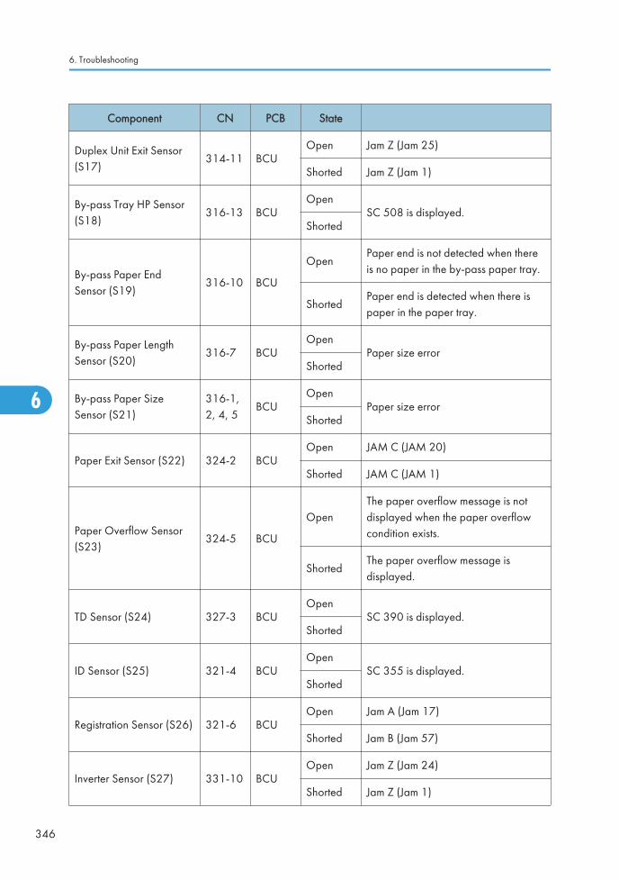
Component CN PCB State
Duplex Unit Exit Sensor(S17)
314-11 BCUOpen Jam Z (Jam 25)
Shorted Jam Z (Jam 1)
By-pass Tray HP Sensor(S18)
316-13 BCUOpen
SC 508 is displayed.Shorted
By-pass Paper EndSensor (S19)
316-10 BCU
OpenPaper end is not detected when thereis no paper in the by-pass paper tray.
ShortedPaper end is detected when there ispaper in the paper tray.
By-pass Paper LengthSensor (S20)
316-7 BCUOpen
Paper size errorShorted
By-pass Paper SizeSensor (S21)
316-1,2, 4, 5
BCUOpen
Paper size errorShorted
Paper Exit Sensor (S22) 324-2 BCUOpen JAM C (JAM 20)
Shorted JAM C (JAM 1)
Paper Overflow Sensor(S23)
324-5 BCU
OpenThe paper overflow message is notdisplayed when the paper overflowcondition exists.
ShortedThe paper overflow message isdisplayed.
TD Sensor (S24) 327-3 BCUOpen
SC 390 is displayed.Shorted
ID Sensor (S25) 321-4 BCUOpen
SC 355 is displayed.Shorted
Registration Sensor (S26) 321-6 BCUOpen Jam A (Jam 17)
Shorted Jam B (Jam 57)
Inverter Sensor (S27) 331-10 BCUOpen Jam Z (Jam 24)
Shorted Jam Z (Jam 1)
6. Troubleshooting
346
6

Component CN PCB State
Original Length Sensor 1(S28)
313-01 SIOOpen The CPU cannot detect the original
size properly. APS and ARE do notfunction correctly.Shorted
Original Length Sensor 2(S29)
313-22 SIOOpen The CPU cannot detect the original
size properly. APS and ARE do notfunction correctly.Shorted
Scanner H.P Sensor(S30)
336-2 BCUOpen SC120
Shorted SC121
Platen Cover Sensor(S31)
336-5 BCUOpen
APS and ARE do not functionproperly.
Shorted No Symptom.
Switches
Component CN PCB State
Front Door Safety Switch(SW1)
321-1/3
BCU
OpenThe Cover Open indicator is not liteven if the front cover is opened.
ShortedThe Cover Open indicator is lit even ifthe front cover is closed.
Right Door Open Switch(SW2)
321-9 BCU
OpenThe Cover Open indicator is not liteven if the right cover is opened.
ShortedThe Cover Open indicator is lit even ifthe right cover is closed.
Electrical Component Defects
347
6

Blown Fuse Conditions
• Use a correct rating fuse for the fuse replacement. Never use a wrong rating fuse. If do so, themachine may be damaged.
FuseRating Symptom when turning on the main
switch115 V 220 to 240 V
PSU
FU1 15 A/250 V 8 A/250V No response.
FU2 10 A/250 V 5 A/250 V No response
FU3 2 A/250 V 2 A/250VAnti-condensation/Tray Heater does notturn on.
FU4 5 A/250 V 5 A/250VOptional finisher does not work thenSC792 is displayed. Paper reaches thebridge unit and stays.
FU5 5 A/250 V 5 A/250 VAll motors do not rotate. "Cover Open"appears.
FU6 5 A/250 V 5 A /250V SC is displayed.
FU7 5 A/250 V 5 A/250 VThe touch panel does not turn on and allmotors do not rotate.
FU8 6.3 A/250 V 6.3 A/250 V No response
6. Troubleshooting
348
6
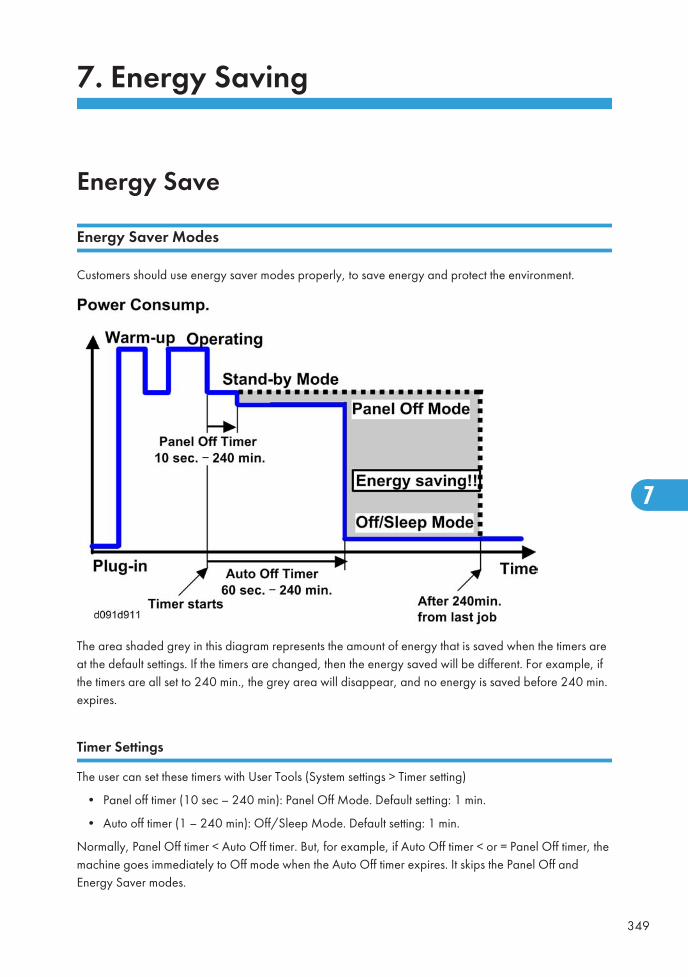
7. Energy Saving
Energy Save
Energy Saver Modes
Customers should use energy saver modes properly, to save energy and protect the environment.
The area shaded grey in this diagram represents the amount of energy that is saved when the timers areat the default settings. If the timers are changed, then the energy saved will be different. For example, ifthe timers are all set to 240 min., the grey area will disappear, and no energy is saved before 240 min.expires.
Timer Settings
The user can set these timers with User Tools (System settings > Timer setting)
• Panel off timer (10 sec – 240 min): Panel Off Mode. Default setting: 1 min.
• Auto off timer (1 – 240 min): Off/Sleep Mode. Default setting: 1 min.
Normally, Panel Off timer < Auto Off timer. But, for example, if Auto Off timer < or = Panel Off timer, themachine goes immediately to Off mode when the Auto Off timer expires. It skips the Panel Off andEnergy Saver modes.
349
7

Example
• Panel off: 1 min.
• Auto Off: 1 min.
• The machine goes to Off mode after 1 minute. Panel Off and Low Power modes are not used.
Return to Stand-by Mode
Recovery time from Off/Sleep Mode
• Machine without HDD: Less than 11 sec.
• Machine with HDD: Less than 10 sec.
Recommendation
We recommend that the default settings should be kept.
• If the customer requests that these settings should be changed, please explain that their energycosts could increase, and that they should consider the effects on the environment of extra energyuse.
• If it is necessary to change the settings, please try to make sure that the Auto Off timer is not toolong. Try with a shorter setting first, such as 30 min., then go to a longer one (such as 60 min.) if thecustomer is not satisfied.
• If the timers are all set to the maximum value, the machine will not begin saving energy until 240minutes has expired after the last job. This means that after the customer has finished using themachine for the day, energy will be consumed that could otherwise be saved.
• If you change the settings, the energy consumed can be measured using SP8941, as explainedbelow.
Energy Save Effectiveness
SP 8941 (Machine Status) keeps a record of the amount of time that the machine spends in each mode.
• 8941-001: Operating mode
• 8941-002: Standby mode
• 8941-003: Panel off mode
• 8941-004: Low power mode
• 8941-005: Off/sleep mode
With this data, and the power consumption values from the specifications, we can estimate the amountof energy that is used by the machine.
7. Energy Saving
350
7

This should only be used as a reference value, because the power consumption specifications aremeasured in a controlled environment with a constant power supply.
To get an exact measurement at the customers site, a watt meter must be used to measure the actualenergy consumed.
To use SP8941 to calculate the energy consumed:
• At the start of the measurement period, read the values of SP8941 001 to 005.
• At the end of the measurement period, read the values of SP8941 001 to 005 again.
• Find the amount of time spent in each mode (subtract the earlier measurement from the latermeasurement).
• Multiply this by the power consumption spec for each mode.
• Convert the result to kWh (kilowatt hours)
Here is an example calculation.
Machine
Condition
SP8941:
MachineStatus
Time atStart (min.)
Time at End(min.)
Runningtime
(hour)
( - )/60 =
PowerconsumptionSpec. (W)
Powerconsumption
(KWH)
( x )/1000=
Operating 001:Operating Time 21089.0 21386.0 5.0 1081.8 5.35
Stand by
(Ready)
002:Standby
Time 306163.0 308046.0 31.4 214.0 6.72
Energy save(Panel off)
003:EnergySaveTime 71386.0 75111.0 62.1 214.0 13.29
Low power
004: LowPowerTime 154084.0 156340.0 37.6 146.0 5.49
Off/Sleep
005: OffModeTime 508776.0 520377.0 193.4 7.0 1.35
Total 32.20
Energy Save
351
7

Paper Save
Effectiveness of Duplex/Combine Function
Duplexing and the combine functions reduce the amount of paper used. This means that less energyoverall is used for paper production, which improves the environment.
1. Duplex:
Reduce paper volume in half!
2. Combine mode:
Reduce paper volume in half!
3. Duplex + Combine:
Using both features together can further reduce paper volume by 3/4!
7. Energy Saving
352
7

To check the paper consumption, look at the total counter and the duplex counter.
The total counter counts all pages printed.
• For one duplex page, the total counter goes up by 2.
• For a duplex job of a three-page original, the total counter goes up by 3.
The duplex counter counts pages that have images on both sides.
• For one duplex page, the duplex counter goes up by 1.
• For a duplex job of a three-page original, the duplex counter will only increase by 1, even thoughtwo sheets are used.
How to calculate the paper reduction ratio
How to calculate the paper reduction ratio, when compared with Single-sided copying, with no 2-in-1combine mode
Paper reduction ratio (%) = Number of sheets reduced: A/Number of printed original images: B x 100
• Number of sheets reduced: A
= Output pages in duplex mode/2 + Number of pages in Single-sided with combine mode +Number of pages in Duplex with combine mode x 3/2A = ((2) + (3) + (4))/2 + (5) + (6) x 3/2
• Number of printed original images: B
= Total counter6 + Number of pages in Single-sided with combine mode + Number of pages inDuplex with combine modeB = (1) + (5) + (6)
• (1) Total counter: SP 8581 001 (pages)
• (2) Single-sided with duplex mode: SP 8421 001 (pages)
• (3) Double-sided with duplex mode: SP 8421 002 (pages)
• (4) Book with duplex mode: SP 8421 003 (pages)
• (5) Single-sided with combine mode: SP 8421 004 (pages)
Paper Save
353
7

• (6) Duplex with combine mode: SP 8421 005 (pages)
7. Energy Saving
354
7

Model OR-C1 Machine Code:
D120/D121/D122/D139/D140/D141
Appendices
August, 2011 Subject to change


TABLE OF CONTENTS1. Appendix: General Specifications
Specifications......................................................................................................................................................3
General Specifications...................................................................................................................................3
Software Accessories.....................................................................................................................................8
Supported Paper Sizes................................................................................................................................10
Optional Equipment.....................................................................................................................................26
2. Appendix: PM Tables
PM Table...........................................................................................................................................................37
Preventive Maintenance Items....................................................................................................................37
Others Yield Parts.........................................................................................................................................42
3. Appendix: Service Call Conditions
Service Call Conditions...................................................................................................................................43
Summary.......................................................................................................................................................43
SC1xx: Scanning.........................................................................................................................................46
SC 2xx: Exposure........................................................................................................................................50
SC3xx: Image Processing – 1....................................................................................................................53
SC4xx: Image Processing - 3.....................................................................................................................56
SC5xx: Paper Feed and Fusing..................................................................................................................58
SC6xx: Device Communication..................................................................................................................68
SC7xx: Peripherals......................................................................................................................................79
SC8xx: Overall System...............................................................................................................................99
SC9xx: Miscellaneous..............................................................................................................................119
4. Appendix: Service Program Mode Tables
System SP Tables-1........................................................................................................................................125
SP1xxx: Feed.............................................................................................................................................125
System SP Tables-2........................................................................................................................................137
SP2xxx: Drum............................................................................................................................................137
System SP Tables-3........................................................................................................................................156
SP3xxx.......................................................................................................................................................156
System SP Tables-4........................................................................................................................................157
SP4xxx: Scanner.......................................................................................................................................157
System SP Tables-5........................................................................................................................................178
SP5xxx: Mode...........................................................................................................................................178
1

System SP Tables-6........................................................................................................................................248
SP6xxx: Peripherals...................................................................................................................................248
System SP Tables-7........................................................................................................................................268
SP7xxx: Data Log......................................................................................................................................268
System SP Tables-8........................................................................................................................................280
SP8xxx: Data Log 2..................................................................................................................................280
INDEX...........................................................................................................................................................321
2

1. Appendix: General Specifications
Specifications
General Specifications
Main Machine
Configuration: Desktop
Copy Process: Dry electrostatic transfer system
Originals: Sheet, Book
Original Size: Platen/ARDF: Max. A3/11" x 17"
Copy Paper Size
Tray 1: A6 SEF to A3/DLT, Custom, Postcard, Envelopes
Tray 2: A5 to A3, DLT, Custom
Bypass: A6 SEF to A3/DLT, Postcard, Custom
Custom Sizes (W x L)
Tray 1: 100 to 297 mm x 148 to 432 mm
Tray 2: 182 to 297 mm x 148 to 432 mm
Bypass: 90 to 305 mm x 148 to 1260 mm
Duplexing A5/HLT to A3/DLT
Paper Weight
Tray 1 and Tray 2: 52 to 157 g/m2 (14 to 42 lbs.)
Bypass: 52 to 157 g/m2 (14 to 42 lbs.)
Duplex: 52 to 105 g/m2 (14 to 28 lbs.)
Copy Speed
D120/D139: 23 cpm (A4 LEF/Letter LEF)
D121/D140: 28 cpm (A4 LEF/Letter LEF)
D122/D141: 33 cpm (A4 LEF/Letter LEF)
Resolution 600 dpi
GradationRead: 256-level (1-dot)
Write: 3 or 4-level (2-dot), 2 level (1-dot)
3
1

1st Copy Print TimeD120/D139: 5.4 sec (A4/LT LEF, Tray 1)
D121/D122/D140/D141: 4.5 sec. (A4/LT LEF, Tray 1)
Warm-up Time
Main Power Switch:
Less than 14 sec. (without HDD)
Less than 20 sec. (with HDD)
Off/Sleep:
Less than 11 sec (without HDD)
Less than 10 sec (with HDD)
Continuous Copies 001 to 999 Sheets
ZoomPlaten Mode: 25% to 400%, in 1% step
ARDF Mode: 25% to 400%, in 1% step
Paper Supply
Tray 1: 500 Sheets
Tray 2: 550 Sheets
Bypass: 100 Sheets
Output CapacityA4, smaller: 500 Sheets face-down
B4, larger: 250 Sheets face-down
Power Source
NA: 120 to 127 V 60 Hz
EU, Asia, China: 220 to 240V 50/60 Hz
Taiwan: 110V 60 Hz
Power Consumption
Full System (Operating) Less than 1.6 KW
Off Mode Less than 1.65 W
Sleep ModeLess than 4 W (NA)
Less than 4.2 W (EU)
1. Appendix: General Specifications
4
1

Dimensions (W x D x H)
Standard
No PTU:
587 x 653 x 709 mm
(23.1" x 25.7" x 30")
With PTU:
587 x 653 x 950 mm
(23.1" x 25.7" x 37.4")
Full System
All Options:
1152 x 653 x 1085 mm
(45.3" x 25.7" x 42.7")
Weight Less than 65 kg (143 lbs.) (basic model)
Noise Emission (Sound PowerLevel)
Stand-by
(Mainframe only):
40 dB (D120/D121/D139/D140)
42.9 dB (D122/D141)
Operating
(Mainframe only):
64.1 dB (D120/D139)
65.8 dB (D121/D140)
67.6 dB (D122/D141)
Operating
(Full-System):
68.1 dB (D120/D139)
69.8 dB (D121/D140)
71.6 dB (D122/D141)
• The above measurements were made in accordance with ISO 7779.
• Full System: Mainframe + ADF + 1-bin Sorter + Paper Tray Unit + Bridge Unit + Finisher
Printer Controller
Printing Speed:
D120/D139: Maximum 23 ppm (A4/LT LEF)
D121/D140: Maximum 28 ppm (A4/LT LEF)
D122/D141: Maximum 33 ppm (A4/LT LEF)
Specifications
5
1

Printer Languages:
PCL 6/5e
PDF Direct
Adobe PostScript 3 (optional)
IPDS (optional)
MediaPrint: JPEG/TIFF (optional)
Resolution andGradation:
PCL 5e:
300 x 300 dpi
600 x 600 dpi : Fast (1-bit)
PCL 6:
600 x 600 dpi : Fast (1-bit)
PDF Direct:
300 x 300 dpi/600 x 600 dpi
PS3:
300 x 300 dpi/600 x 600 dpi
XPS:
600 x 600 dpi : Fast (1-bit)
IPDS:
300 x 300 dpi/ 600 x 600 dpi
Printing speed:
D120/D139: 23 ppm (A4/LT LEF)
D121/D140: 28 ppm (A4/LT LEF)
D122/D141: 33 ppm (A4/LT LEF)
Resident Fonts:
PCL 6/5e (Standard):
45 Compatible fonts
13 International fonts
6 Bitmap fonts
Adobe PostScript 3 (Optional):
136 fonts
IPDS (Optional):
108 fonts
1. Appendix: General Specifications
6
1

Host Interfaces:
USB2.0 Type A and Type B: Standard
Ethernet (100 Base-TX/10 Base-T): Standard
Gigabit Ethernet (1000 Base-T): Optional
IEEE1284 parallel x 1: Optional
IEEE802.11a/b/g (Wireless LAN): Optional
Bluetooth (USB type): Optional
Network Protocols: TCP/IP (IPv4, IPv6), IPX/SPX
RAM
Maximum
Basic model: 512 MB
SP model: 1 GB (Resident 512 MB + Additional 512 MB)
• Additional 512 MB (basic model) is required for all printer/scannerunit and printer units.
Scanner Specification
Standard ScannerResolution:
Main scan/Sub scan
600 dpi
Scanning Speed29 ipm (E-mail/Scan-to-Folder/Network Delivery Scanner (A4 LEF, Text200 dpi, Compression (Default Level))
Available scanningResolution Range:
100 to1200 dpi (when used as a Network TWAIN scanner)
100, 200, 300, 400, 600 dpi (when used as a network delivery scanner,Scan-to-Folder, Scan-to-Email, or Document Server storage)
Grayscales/Fullcolor: 1 bit or 8 bits/pixel each for RGB
Interface:Ethernet 10Base-T / 100Base-TX, Gigabit Ethernet (1000Base-T),Wireless LAN (IEEE 802.11a/b/g,g)
Compression Method:B&W: TIFF (MH, MR, MMR), Gray Scale
Full Color: JPEG
Video MemoryCapacity:
109.41 MB (A4, Full Color, 600dpi)
Specifications
7
1

Image StorageCapacity:
Number of originals per file: Maximum 1,000 pages
Maximum of files: 3,000 files
Max.Storage on Doc.Server: 9,000 pages (B&W (ITU-T No.1/200 dpiMMR)
Software Accessories
The printer drivers and utility software are provided on one CD-ROM. An auto-run installer allows you toselect which components to install.
Printer Drivers
Printer LanguageWindows XP, Server 2003, Server 2008,
Vista, 7
MacOSX10.2
or later
PCL5c/ PCL6
Yes No
PS3 Yes Yes
RPCS No No
• The PCL5c/6 and PS3 drivers are provided on printer/scanner CD-ROM.
• The PS3 drivers are all genuine Adobe PS drivers, except for Windows XP/Server 2003/Server2008/Vista/7. A PPD file for each operating system is provided with the driver.
• The PPD installer for Macintosh supports Mac OS X 10.2 or later versions.
Scanner and LAN Fax drivers
Printer LanguageWindows XP, Server 2003,
Server 2008, Vista, 7
MacOSX10.2
or later
Network TWAIN Yes No
LAN-FAX Yes No
1. Appendix: General Specifications
8
1

• The Network TWAIN and LAN Fax drivers are provided on the printer and scanner drivers CD-ROM.
• This software lets you fax documents directly form your PC. Address Book Editor and Cover SheetEditor are to be installed as well. (These require the optional fax unit.)
Utility Software
Software Description
Font Manager
(XP/Vista)
A font management utility with screen fonts for the printer
This is provided on the printer scanner CD-ROM
Smart Device Monitor for Admin (XP/Server 2003/Server 2008/Vista/7)
A printer management utility for network administrators. NIBsetup utilities are also available.
This is provided on the web.
DeskTopBinder – SmartDeviceMonitorfor Client (XP/Server 2003/Server2008/Vista/7)
A printer management utility for client users.
A utility for peer-to-peer printing over a NetBEUI or TCP/IPnetwork.
A peer-to-peer print utility over a TCP/IP network. Thisprovides the parallel printing and recovery printing features.
This is provided on the web.
Printer Utility for Mac
(Mac)
A utility for peer-to-peer printing over a NetBEUI or TCPThis software provides several convenient functions forprinting from Macintosh clients.
This is provided on the web.
DeskTopBinder Lite
(XP/Server 2003/Server 2008/Vista/7)
DeskTopBinder Lite itself can be used as personal documentmanagement software and can manage both image dataconverted from paper documents and application filessaved in each client’s PC.
This is provided on the web.
Specifications
9
1

Supported Paper Sizes
Paper Feed (North America)
BT: By-pass Tray, T1: Tray 1, T2/3/4: Tray 2/3/4, LCT: Large Capacity Tray: 2000-sheet, DU:Duplex Unit
PaperSize
(W x L)BT T1 T2/3/4 LCT DU
A3 W 12" x 18" M - - - -
A3 SEF 297 x 420mm M S S - M
A4 SEF 210 x 297mm M A A - M
A4 LEF 297 x 210mm M S S S M
A5 SEF 148 x 210mm M M - - M
A5 LEF 210 x 148mm M S A - M
A6 SEF 105 x 148mm M A - - -
B4 SEF 257 x 364mm M S S - M
B5 SEF 182 x 257mm M A A - M
B5 LEF 257 x 182mm M S M - M
B6 SEF 128 x 182mm M M - - -
Ledger 11" x 17" A A A - M
Letter SEF 8.5" x 11" A A A - M
Letter LEF 11" x 8.5" A A A M M
Legal SEF 8.5" x 14" M A A - M
Government LegalSEF
8.25" x 14" M M M - M
Half Letter SEF 5.5" x 8.5" A A A - M
Executive SEF 7.25" x 10.5" M M M - M
Executive LEF 10.5" x 7.25" M A A - M
1. Appendix: General Specifications
10
1

PaperSize
(W x L)BT T1 T2/3/4 LCT DU
F SEF 8" x 13" M M M - M
Foolscap SEF 8.5" x 13" M M M - M
Folio SEF
8.25" x 13" M M M - M
11" x 15" M M M - M
10" x 14" M M M - M
8" x 10" M M M - M
8K 267 x 390mm M M M - M
16K SEF 195 x 267mm M M M - M
16K LEF 267 x 195mm M M M - M
Custom M M M - -
Com10 Env. 4.125" x 9.5" M M - - -
Monarch Env. 3.875" x 7.5" M M - - -
C6 Env. 114 x 162mm M M - - -
C5 Env. 162 x 229mm M M - - -
DL Env. 110 x 220mm M M - - -
Remarks:
A Supported: the sensor detects the paper size.
M Supported: the user specifies the paper size.
S Supported: depends on a technician adjustment
- Not supported
Paper Feed (Europe/ Asia)
BT: By-pass Tray, T1: Tray 1, T2/3/4: Tray 2/3/4, LCT: Large Capacity Tray: 2000-sheet, DU:Duplex Unit
Specifications
11
1

PaperSize
(W x L)BT T1 T2/3/4 LCT DU
A3 W 12" x 18" M - - - -
A3 SEF 297 x 420mm A A A - M
A4 SEF 210 x 297mm A A A - M
A4 LEF 297 x 210mm A A A M M
A5 SEF 148 x 210mm A M - - M
A5 LEF 210 x 148mm A A A - M
A6 SEF 105 x 148mm M M - - -
B4 SEF 257 x 364mm A A A - M
B5 SEF 182 x 257mm A A A - M
B5 LEF 257 x 182mm A A A - M
B6 SEF 128 x 182mm A M - - -
Ledger 11" x 17" M S S - M
Letter SEF 8.5" x 11" M A A - M
Letter LEF 11" x 8.5" M S S S M
Legal SEF 8.5" x 14" M S S - M
Government LegalSEF
8.25" x 14" M M M - M
Half Letter SEF 5.5" x 8.5" M S S - M
Executive SEF 7.25" x 10.5" M M M - M
Executive LEF 10.5" x 7.25" M S S - M
F SEF 8" x 13" M M M - M
Foolscap SEF 8.5" x 13" M M M - M
1. Appendix: General Specifications
12
1

PaperSize
(W x L)BT T1 T2/3/4 LCT DU
Folio SEF
8.25" x 13" M M M - M
11" x 15" M M M - M
10" x 14" M M M - M
8" x 10" M M M - M
8K 267 x 390mm M M M - M
16K SEF 195 x 267mm M M M - M
16K LEF 267 x 195mm M M M - M
Custom M M M - -
Com10 Env. 4.125" x 9.5" M M - - -
Monarch Env. 3.875" x 7.5" M M - - -
C6 Env. 114 x 162mm M M - - -
C5 Env. 162 x 229mm M M - - -
DL Env. 110 x 220mm M M - - -
Remarks:
A Supported: the sensor detects the paper size.
M Supported: the user specifies the paper size.
S Supported: depends on a technician adjustment
- Not supported
Paper Exit (Mainframe and optional trays)
Main: Mainframe/ 1-bin: 1-bin tray/ Shift: Shift Tray
Paper Size (W x L) Main 1-bin Shift
A3 W 12" x 18" Y - Y
Specifications
13
1

Paper Size (W x L) Main 1-bin Shift
A3 SEF 297 x 420 mm Y Y Y
A4 SEF 210 x 297 mm Y Y Y
A4 LEF 297 x 210 mm Y Y Y
A5 SEF 148 x 210 mm Y Y Y
A5 LEF 210 x 148 mm Y Y Y
A6 SEF 105 x 148 mm Y - Y
B4 SEF 257 x 364 mm Y Y Y
B5 SEF 182 x 257 mm Y Y Y
B5 LEF 257 x 182 mm Y Y Y
B6 SEF 128 x 182 mm Y - Y
Ledger 11" x 17" Y Y Y
Letter SEF 8.5" x 11" Y Y Y
Letter LEF 11" x 8.5" Y Y Y
Legal SEF 8.5" x 14" Y Y Y
Government
Legal SEF8.25" x 14" Y Y Y
Half Letter SEF 5.5" x 8.5" Y Y Y
Executive SEF 7.25" x 10.5" Y Y Y
Executive LEF 10.5" x 7.25" Y Y Y
F SEF 8" x 13" Y Y Y
Foolscap SEF 8.5" x 13" Y Y Y
Folio SEF
8.25" x 13" Y Y Y
11" x 15" Y Y Y
10" x 14" Y Y Y
8" x 10" Y Y Y
1. Appendix: General Specifications
14
1

Paper Size (W x L) Main 1-bin Shift
8K 267 x 390 mm Y - Y
16K SEF 195 x 267 mm Y - Y
16K LEF 267 x 195 mm Y - Y
Custom Y Y Y
Com10 Env. 4.125" x 9.5" Y - Y
Monarch Env. 3.875" x 7.5" Y - Y
C6 Env. 114 x 162 mm Y - Y
C5 Env. 162 x 229 mm Y - Y
DL Env. 110 x 220 mm Y - Y
Remarks:
Y Supported
- Not supported
Paper Exit (1000-Sheet Booklet Finisher)
MF: Main Frame, Prf: Proof, Clr: Clear, Shf: Shift, Stp: Staple, SS: Saddle Stitch
Paper Size (W x L) MF1000-sheet booklet finisher (Shift/Staple)
Prf Clr Shf Stp SS
A3 W 12" x 18" Y Y Y - - -
A3 SEF 297 x 420 mm Y Y Y Y 30 10
A4 SEF 210 x 297 mm Y Y Y Y 50 10
A4 LEF 297 x 210 mm Y Y Y Y 50 -
A5 SEF 148 x 210 mm Y Y - - - -
A5 LEF 210 x 148 mm Y Y - - - -
A6 SEF 105 x 148 mm Y Y - - - -
Specifications
15
1

Paper Size (W x L) MF1000-sheet booklet finisher (Shift/Staple)
Prf Clr Shf Stp SS
B4 SEF 257 x 364 mm Y Y Y Y 30 10
B5 SEF 182 x 257 mm Y Y - - 50 10
B5 LEF 257 x 182 mm Y Y Y Y 50 -
B6 SEF 128 x 182 mm Y Y - - - -
Ledger 11" x 17" Y Y Y Y 30 10
Letter SEF 8.5" x 11" Y Y Y Y 50 10
Letter LEF 11" x 8.5" Y Y Y Y 50 -
Legal SEF 8.5" x 14" Y Y Y Y 30 10
Government
Legal SEF8.25" x 14" Y Y Y Y 30 -
Half Letter SEF 5.5" x 8.5" Y Y - - - -
Executive SEF 7.25" x 10.5" Y Y Y Y 50 -
Executive LEF 10.5" x 7.25" Y Y Y Y 50 -
F SEF 8" x 13" Y Y Y Y 30 -
Foolscap SEF 8.5" x 13" Y Y Y Y 30 -
Folio SEF
8.25" x 13" Y Y Y Y 30 -
11" x 15" Y Y Y Y 30 -
10" x 14" Y Y Y Y 30 -
8" x 10" Y Y Y Y 50 -
8K 267 x 390 mm Y Y Y Y 30 -
16K SEF 195 x 267 mm Y Y Y Y 50 -
16K LEF 267 x 195 mm Y Y Y Y 50 -
Custom Y Y Y - - -
Com10 Env. 4.125" x 9.5" Y - - - - -
1. Appendix: General Specifications
16
1

Paper Size (W x L) MF1000-sheet booklet finisher (Shift/Staple)
Prf Clr Shf Stp SS
Monarch Env. 3.875" x 7.5" Y - - - - -
C6 Env. 114 x 162 mm Y - - - - -
C5 Env. 162 x 229 mm Y - - - - -
DL Env. 110 x 220 mm Y - - - - -
MF: Main Frame, E2P: Europe 2 Holes Punch, N2P: North America 2 Holes Punch, N3P: NorthAmerica 3 Holes Punch, E4P: Europe 4 Holes Punch, S4P: North Europe 4 Holes Punch
Paper Size (W x L) MF1000-sheet booklet finisher (Punch)
E2P N2P N3P E4P S4P
A3 W 12" x 18" Y - - - - -
A3 SEF 297 x 420 mm Y Y Y Y Y Y
A4 SEF 210 x 297 mm Y Y - - - Y
A4 LEF 297 x 210 mm Y Y Y Y Y Y
A5 SEF 148 x 210 mm Y - Y - - -
A5 LEF 210 x 148 mm Y Y - - - -
A6 SEF 105 x 148 mm Y - - - - -
B4 SEF 257 x 364 mm Y Y Y Y Y Y
B5 SEF 182 x 257 mm Y Y Y - - Y
B5 LEF 257 x 182 mm Y Y Y Y Y Y
B6 SEF 128 x 182 mm Y - - - - -
Ledger 11" x 17" Y Y Y Y Y Y
Letter SEF 8.5" x 11" Y Y Y - - -
Letter LEF 11" x 8.5" Y Y Y Y Y Y
Legal SEF 8.5" x 14" Y Y Y - - Y
Specifications
17
1

Paper Size (W x L) MF1000-sheet booklet finisher (Punch)
E2P N2P N3P E4P S4P
Government
Legal SEF8.25" x 14" Y Y Y - - Y
Half Letter SEF 5.5" x 8.5" Y Y Y - - Y
Executive SEF 7.25" x 10.5" Y Y Y - - Y
Executive LEF 10.5" x 7.25" Y Y Y Y Y Y
F SEF 8" x 13" Y Y Y - - Y
Foolscap SEF 8.5" x 13" Y Y Y - - Y
Folio SEF
8.25" x 13" Y Y Y - - Y
11" x 15" Y - - - - -
10" x 14" Y - - - - -
8" x 10" Y Y Y - - Y
8K 267 x 390 mm Y Y Y Y Y Y
16K SEF 195 x 267 mm Y Y Y - - Y
16K LEF 267 x 195 mm Y Y Y Y Y Y
Custom Y - - - - -
Com10 Env. 4.125" x 9.5" Y - - - - -
Monarch Env. 3.875" x 7.5" Y - - - - -
C6 Env. 114 x 162 mm Y - - - - -
C5 Env. 162 x 229 mm Y - - - - -
DL Env. 110 x 220 mm Y - - - - -
Remarks:
Y Supported
10 Output up to 10 sheets
1. Appendix: General Specifications
18
1

30 Output up to 30 sheets
50 Output up to 50 sheets
- Not supported
Paper Exit (1000-Sheet Finisher and 500-Sheet Finisher)
MF: Main Frame, Prf: Proof, Clr: Clear, Shf: Shift, Stp: Staple
PaperSize
(W x L)MF
1000-sheet finisher 500-sheet finisher
Prf Clr Shf Stp Clr Shf Stp
A3 W 12" x 18" Y Y Y - - - - -
A3 SEF297 x 420mm
Y Y Y Y 30 Y Y 30
A4 SEF210 x 297mm
Y Y Y Y 50 Y Y 50
A4 LEF297 x 210mm
Y Y Y Y 50 Y Y 50
A5 SEF148 x 210mm
Y Y - - - - - -
A5 LEF210 x 148mm
Y Y - - - - - -
A6 SEF105 x 148mm
Y - - Y 30 Y - -
B4 SEF257 x 364mm
Y Y Y Y 30 Y Y 30
B5 SEF182 x 257mm
Y Y Y Y 50 Y Y 50
B5 LEF257 x 182mm
Y Y - - 50 Y Y 50
B6 SEF128 x 182mm
Y Y - - - Y - -
Ledger 11" x 17" Y Y Y Y 30 - Y 30
Specifications
19
1

PaperSize
(W x L)MF
1000-sheet finisher 500-sheet finisher
Prf Clr Shf Stp Clr Shf Stp
Letter SEF 8.5" x 11" Y Y Y Y 50 Y Y 50
Letter LEF 11" x 8.5" Y Y Y Y 50 Y Y 50
Legal SEF 8.5" x 14" Y Y Y Y 30 Y Y 30
Government
Legal SEF8.25" x 14" Y Y Y Y 30 Y Y 30
Half Letter SEF 5.5" x 8.5" Y Y - - - - - -
Executive SEF 7.25" x 10.5" Y Y Y Y 50 Y Y 50
Executive LEF 10.5" x 7.25" Y Y Y Y 50 Y Y 50
F SEF 8" x 13" Y Y Y Y 30 Y Y 30
Foolscap SEF 8.5" x 13" Y Y Y Y 30 Y Y 30
Folio SEF
8.25" x 13" Y Y Y Y 30 Y Y 30
11" x 15" Y Y Y Y 30 Y Y 30
10" x 14" Y Y Y Y 30 Y Y 30
8" x 10" Y Y Y Y 50 Y Y 50
8K267 x 390mm
Y Y Y Y 30 Y Y 30
16K SEF195 x 267mm
Y Y Y Y 50 Y Y 50
16K LEF267 x 195mm
Y Y Y Y 50 Y Y 50
Custom Y Y - - - Y Y -
Com10 Env. 4.125" x 9.5" Y - - - - - - -
Monarch Env. 3.875" x 7.5" Y - - - - - - -
C6 Env.114 x 162mm
Y - - - - - - -
1. Appendix: General Specifications
20
1

PaperSize
(W x L)MF
1000-sheet finisher 500-sheet finisher
Prf Clr Shf Stp Clr Shf Stp
C5 Env.162 x 229mm
Y - - - - - - -
DL Env.110 x 220mm
Y - - - - - - -
Remarks:
Y Supported
30 Output up to 30 sheets
50 Output up to 50 sheets
- Not supported
Paper Exit (Internal Finisher)
MF: Main Frame, Clr: Clear, Shf: Shift, Stp: Staple,
Paper Size (W x L) MFInternal finisher(Shift/Staple)
Clr Shf Stp
A3 W 12" x 18" Y - - -
A3 SEF 297 x 420 mm Y Y 30 Y
A4 SEF 210 x 297 mm Y Y 50 Y
A4 LEF 297 x 210 mm Y Y 50 Y
A5 SEF 148 x 210 mm Y - - -
A5 LEF 210 x 148 mm Y - - -
A6 SEF 105 x 148 mm Y - - -
B4 SEF 257 x 364 mm Y Y 30 Y
B5 SEF 182 x 257 mm Y Y 50 Y
B5 LEF 257 x 182 mm Y Y 50 Y
Specifications
21
1

Paper Size (W x L) MFInternal finisher(Shift/Staple)
Clr Shf Stp
B6 SEF 128 x 182 mm Y - - -
Ledger 11" x 17" Y Y 30 Y
Letter SEF 8.5" x 11" Y Y 50 Y
Letter LEF 11" x 8.5" Y Y 50 Y
Legal SEF 8.5" x 14" Y Y 30 Y
Government
Legal SEF8.25" x 14" Y - 30 -
Half Letter SEF 5.5" x 8.5" Y - - -
Executive SEF 7.25" x 10.5" Y Y 50 Y
Executive LEF 10.5" x 7.25" Y Y 50 -
F SEF 8" x 13" Y - - -
Foolscap SEF 8.5" x 13" Y - 30 Y
Folio SEF
8.25" x 13" Y Y 30 -
11" x 15" Y - - -
10" x 14" Y - - -
8" x 10" Y - - -
8K 267 x 390 mm Y Y 30 Y
16K SEF 195 x 267 mm Y Y 30 Y
16K LEF 267 x 195 mm Y Y 30 Y
Custom Y - - -
Com10 Env. 4.125" x 9.5" Y - - -
Monarch Env. 3.875" x 7.5" Y - - -
C6 Env. 114 x 162 mm Y - - -
C5 Env. 162 x 229 mm Y - - -
1. Appendix: General Specifications
22
1

Paper Size (W x L) MFInternal finisher(Shift/Staple)
Clr Shf Stp
DL Env. 110 x 220 mm Y - - -
MF: Main Frame, E2P: Europe 2 Holes Punch, N2P: North America 2 Holes Punch, N3P: NorthAmerica 3 Holes Punch, E4P: Europe 4 Holes Punch, S4P: North Europe 4 Holes Punch
Paper Size (W x L) MFInternal finisher(Punch)
E2P N2P N3P E4P S4P
A3 W 12" x 18" Y - - - - Y
A3 SEF 297 x 420 mm Y Y Y Y Y Y
A4 SEF 210 x 297 mm Y Y - - Y Y
A4 LEF 297 x 210 mm Y Y Y Y Y Y
A5 SEF 148 x 210 mm Y - - - - Y
A5 LEF 210 x 148 mm Y - - - - Y
A6 SEF 105 x 148 mm Y - - - - Y
B4 SEF 257 x 364 mm Y - - - Y Y
B5 SEF 182 x 257 mm Y - - - Y Y
B5 LEF 257 x 182 mm Y - - - Y Y
B6 SEF 128 x 182 mm Y - - - - Y
Ledger 11" x 17" Y Y Y Y Y Y
Letter SEF 8.5" x 11" Y Y - - - Y
Letter LEF 11" x 8.5" Y Y Y Y Y Y
Legal SEF 8.5" x 14" Y Y - - Y Y
Government
Legal SEF8.25" x 14" Y - - - - Y
Half Letter SEF 5.5" x 8.5" Y - - - - Y
Executive SEF 7.25" x 10.5" Y Y - - Y Y
Specifications
23
1

Paper Size (W x L) MFInternal finisher(Punch)
E2P N2P N3P E4P S4P
Executive LEF 10.5" x 7.25" Y - - - - Y
F SEF 8" x 13" Y - - - - Y
Foolscap SEF 8.5" x 13" Y Y - - Y Y
Folio SEF
8.25" x 13" Y - - - - Y
11" x 15" Y - - - - Y
10" x 14" Y - - - - Y
8" x 10" Y - - - - Y
8K 267 x 390 mm Y - - - - Y
16K SEF 195 x 267 mm Y - - - - Y
16K LEF 267 x 195 mm Y - - - - Y
Custom Y - - - - Y
Com10 Env. 4.125" x 9.5" Y - - - - Y
Monarch Env. 3.875" x 7.5" Y - - - - Y
C6 Env. 114 x 162 mm Y - - - - Y
C5 Env. 162 x 229 mm Y - - - - Y
DL Env. 110 x 220 mm Y - - - - Y
Remarks:
Y Supported
30 Output up to 30 sheets
50 Output up to 50 sheets
- Not supported
1. Appendix: General Specifications
24
1

Platen/ARDF Original Size Detection
Size
(width x length) [mm]
Platen ARDF Platen ARDF
Inches Inches Metric Metric
A3 (297 x 420) L - Y Y*3 Y
B4 (257 x 364) L - - Y*3 Y
A4 (210 x 297) L Y*3 Y Y*3 Y
A4 (297 x 210) S Y*3 Y Y*3 Y
B5 (182 x 257) L - - Y*3 Y
B5 (257 x 182) S - - Y*3 Y
A5 (148 x 210) L - - Y*1 Y
A5 (210 x 148) S - - Y*3 Y
B6 (128 x 182) L - - - -
B6 (182 x 128) S - - - -
11" x 17" (DLT) Y Y*2 - Y*2
11" x 15" - Y*2 - -
10" x 14" - Y - -
8.5" x 14" (LG) Y Y*2 - -
8.5" x 13" (F4) - Y*2 Y*4 Y*4
8.25" x 13" - - Y*4 Y*4
8" x 13"(F) - - Y*4 Y*4
8.5" x 11" (LT) Y*3 Y*2 Y*3 Y*2
11" x 8.5" (LT) Y*3 Y*2 Y*3 Y*2
8" x 10" - Y*2 - -
5.5" x 8.5" (HLT) Y*1 Y - -
8.5" x 5.5" (HLT) Y Y - -
Specifications
25
1

8K (267 x 390) - - Y*3 Y*2
16K L (195 x 267) - - Y*3 Y*2
16K S (267 x 195) - - Y*3 Y*2
7.25" x 10.5" (Executive) - Y - -
10.5" x 7.25" (Executive) - Y*2 - -
*1: Use SP4-303 to detect original sizes as A5 lengthwise/HLT when the message “Can-t detectoriginal size” shows.
*2: The machine can detect the paper size depending on the setting of SP6-016-1.
*3: The machine can detect the paper size depending on the setting of SP4-305-1.
*4: The machine can detect the paper size depending on the setting of SP5-126-1.
Remarks:
Y Supported
- Not supported
Optional Equipment
ARDF (D578)
Paper Size/Weight:
SimplexSize A3 to A5, DLT to HLT
Weight 40 to 128 g/m2 (10 to 34 lbs.)
DuplexSize A3 to A5, DLT to HLT
Weight 52 to 105 g/m2 (14 to 28 lbs.)
Table Capacity: 50 sheets (80 g/m2, 20 lbs.)
Original Standard Position: Rear left corner
Separation: Feed belt and separation roller
Original Transport: Roller transport
Original Feed Order: From the top original
1. Appendix: General Specifications
26
1

Supported MagnificationRatios:
33.3 to 200 %
Power Source: DC 24V, 5V from the scanner unit
Power Consumption: 50 W or less
Dimensions (W × D × H) : 550 x 496 x 120 mm (21.7" x 19.5" x 4.7")
Weight: 10 kg (22 lbs.)
1-Bin Tray (D582)
Paper Size: A5 LEF to A3, HLT to DLT
Paper Weight: 60 g/m2 to 105 g/m2 (16 lbs. to 28 lbs.)
Tray Capacity:100 sheets (80 g/m2, 20 lbs.): A4 or smaller
50 sheets (80 g/m2, 20 lbs.): B4 or larger
Power Source: DC 5 V (from copier)
Power Consumption: 1 W
Weight: 2 kg (4.4 lbs.)
Dimensions (W x D x H): 502 x 417 x 142 mm (19.8" x 16.4" x 5.6")
Bridge Unit (D584)
Paper Size:
Standard sizes:
A6 LEF to A3, HLT to DLT
Non-standard sizes:
Width: 90 to 305 mm, Length: 148 to 600 mm
Paper Weight: 52 g/m2 to 157 g/m2 (14 lbs. to 42 lbs.)
Tray Capacity:
125 sheets (80 g/m2, 20 lbs.): B4 or larger
250 sheets (80 g/m2, 20 lbs.): A4 or smaller
10 sheets: Envelopes
Power Source: DC 24 V, 5 V (form copier)
Specifications
27
1

Dimensions (W x D x H): 420 x 513 x 145 mm (16.5" x 20.2" x 5.7")
Weight 4.0 kg (8.8 lbs.)
Shift Tray Unit (D583)
Paper Size:
Standard Size:
A6 LEF to A3, HLT LEF to DLT
Non-standard Size:
Width: 90 to 305 mm, Length: 148 to 600 mm
Paper Weight: 57 to 157 g/m2 (14 to 42 lbs.)
Tray Capacity:125 sheets (80 g/m2, 20 lbs.): B4 or larger
250 sheets (80 g/m2, 20 lbs.): A4 or smaller
Power Source: DC 5 V, 24 V (from copier)
Power Consumption:Max: 4.4 W
Average: 3.9 W
Weight: 2 kg (4.4 lbs.)
Dimensions (W x D x H):423 x 467 x 113 mm (16.7" x 18.4" x 4.4")(without basement)
423 x 469 x 122 mm (16.7" x 18.5" x 4.8") (with basement)
Paper Feed Unit (D579)
Paper Size: A5 to A3, 51/2" x 81/2" SEF to 11" x 17"
Paper Weight: 52 – 157 g/m2, 14 – 42 lbs.
Tray Capacity: 550 sheets (80 g/m2, 20 lbs.) x 1 tray
Paper Feed System: FRR
Paper Height Detection: 5 steps (100%, 70%, 30%, 10%, Empty)
1. Appendix: General Specifications
28
1

Power Source:
• 24 Vdc and 5Vdc (from the copier/printer):
• 120 Vac (120 V version) from the copier/printer when theoptional tray heater is installed
• 220 – 240 Vac (230 V version) from the copier/printerwhen the optional tray heater is installed
Power Consumption:Max: 37 W
Average: 22 W
Weight: 15 kg (33 lbs.)
Dimensions (W x D x H): 580 x 629 x 120 mm (22.8" x 24.8" x 4.7")
Paper Feed Unit (D580)
Paper Size: A5 to A3, 51/2" x 81/2" SEF to 11" x 17"
Paper Weight: 52 – 157 g/m2, 14 – 42 lbs.
Tray Capacity: 550 sheets (80 g/m2, 20 lbs.) x 2 trays
Paper Feed System: FRR
Paper Height Detection: 5 steps (100%, 70%, 30%, 10%, Empty)
Power Source:
• 24 Vdc and 5Vdc (from the copier/printer):
• 120 Vac (120 V version) from the copier/printer when theoptional tray heater is installed
• 220 – 240 Vac (230 V version) from the copier/printerwhen the optional tray heater is installed
Power Consumption:Max: 40 W
Average: 25 W
Weight: 26 kg (57 lbs.)
Dimensions (W x D x H): 580 x 629 x 260 mm (22.8" x 24.8" x 10.2")
LCT (D581)
Paper Size: A4 LEF/LT LEF
Specifications
29
1

Paper Weight: 52 g/m2 to 157 g/m2, 14lbs. to 42lbs.
Tray Capacity: 2,000 sheets (80 g/m2, 20lbs.)
Remaining Paper Detection:5 steps (100%, 70%, 30%, 10%, Empty): Right Tray
4 steps (100%, 70%, 30%, Empty): Left Tray
Power Source:
• DC 24 V, 5 V (from copier/printer)
• 120 Vac (120 V version) from the copier/printer when theoptional tray heater is installed
• 220 – 240 Vac (230 V version) from the copier/printerwhen the optional tray heater is installed
Power Consumption: 45 W (Max.)/27 W (Ave.)
Weight: 26 kg (57 lbs.)
Dimensions (W x D x H): 580 x 629 x 260 mm (22.8" x 24.7" x 10.2")
500-Sheet Finisher (D585)
Face-down Output Size
12"x18", A3 SEF to A6 SEF, DLT to HLT SEF
Shift sizes: A3 SEF to B5 SEF
A5, B6, A6 SEF labels possible
Paper Thickness52 g/m2 (14 lbs.) to 157 g/m2 (42 lbs.)
Up to 253 g/m2 (68 lbs.) without shift
Stapling
Stack Height for Stapling50 sheets: A4, LT and smaller
30 sheets: B4, LG and larger
Size A3 SEF to B5 SEF (can be mixed if same width)
Stack Thickness 64 g/m2 (16 lbs.) to 157 g/m2 (42 lbs.)
Stapling PositionsFront/Oblique: 1, Front/Parallel: 1
Rear/Oblique: 1, Rear/Parallel: 1, 2 locations
Output Tray Capacity
Non-staple Mode 500 sheets: A4, LT and smaller
1. Appendix: General Specifications
30
1

Staple Mode
250 sheets: B4, LGand larger
Stack Size (Stapling)
Stacks Size
2 to 9 Sheets 55 to 46A4, B5, LT LEF
10 to 50 Sheets 45 to 10
2 to 9 Sheets 55 to 27A4, B5, LT SEF
10 to 50 Sheets 25 to 8
2 to 9 Sheets 55 to 27A3, B4, DLT, LG
10 to 30 Sheets 25 to 8
Stacking Non-Stapling ModeVertical: 15 mm or less
Horizontal: 15 mm or less
Jogging Precision
2 to 30 Sheets 2 mm
31 to 50 Sheets 3 mm
Dimensions (W x D x H) 396 x 551 x 276 mm (15.6" x 21.7" x 10.9")
Weight 12 kg (26.4 lbs.)
1000-Sheet Finisher (D588)
Upper Tray
Paper Size:A3 to A611" x 17" to 5.5" x 8.5"
Paper Weight: 60 to 157 g/m2 (16 to 42 lbs.)
Paper Capacity:
250 sheets (A4 LEF/8.5" x 11" SEF or smaller)
50 sheets (A4, 8.5" x 11" or smaller)
30 sheets (B4, 8.5" x 14" or larger)
Lower Tray
Specifications
31
1

Paper Size:
No staple mode:
A3 to B5, DLT to HLT
Staple mode:
A3, B4, A4, B5, DLT to LT
Paper Weight:No staple mode: 60 to 157 g/m2 (16 to 42 lbs.)
Staple mode: 64 to 90 g/m2 (17 to 24 lbs.)
Stapler Capacity:30 sheets (A3, B4, DLT, LG)
50 sheets (A4, B5 LEF, LT)
Paper Capacity:
No staple mode:
1,000 sheets (A4/LT or smaller: 80 g/m2, 20 lbs.)
500 sheets (A3, B4, DLT, LG: 80 g/m2, 20 lbs.)
Staple mode: (80 g/m2, 20 lbs., number of sets)
Set Size2 to 9
10 to 50 -
Size 10 to 30 31 to 50
A4/LT LEFB5 LEF
100 100 to 20 100 to 20
A4/LT SEF 100 50 to 10 50 to 10
A3, B4, DLT, LG 50 50 to 10 -
Staple positions:1 Staple: 2 positions (Front, Rear)
2 Staples: 2 positions (Upper, Left)
Staple Replenishment: Cartridge (5,000 staples/cartridge)
Power Source: DC 24 V, 5 V (from the copier/printer)
Power Consumption: 50 W
Weight: 25 kg (55.2 lbs.)
Dimensions (W x D x H): 527 x 520 x 790 mm (20.8" x 20.5" x 31.1")
1. Appendix: General Specifications
32
1

1000-Sheet Booklet Finisher (B589) and Punch Unit (B807)
Print Paper Size:
No punch mode:
A3/11" x 17" to A5/8.5" x 5.5" (LEF)
Punch mode:
2 holes: A3/11" x 17" to B6/5.5" x 8.5" (SEF) or A4/8.5" x11" to A5/8.5" x 5.5" (LEF)3 holes:
A3, B4, 11" x 17" (SEF) or A4, B5, 8.5" x 11" (LEF)
4 holes (Europe):
A3, B4, 11" x 17" (SEF) or A4, B5, 8.5" x 11" (LEF)
4 holes (North Europe):
A3/11" x 17" to B6/5.5" x 8.5" (SEF)
Staple mode:
A3/11" x 17" to B5/8.5" x 11"
Paper Weight:
No punch mode:
52 to 256 g/m2 (14 to 68 lbs.) (Shift tray)
52 to 105 g/m2 (14 to 28 lbs.) (Proof tray)
Punch mode:
52 to 163 g/m2 (14 to 43 lbs.)
Staple mode:
64 to 90 g/m2 (17 to 24 lbs.)
Label/Thick paper/OHP cannot be stapled
Tray Capacity:
[Proof tray]
100 sheets: A4, 8.5" x 11" or less
50 sheets: B4, 8.5" x 14" or more
[Shift tray]
1000 sheets: A4, 8.5" x 11" (LEF) or smaller
500 sheets: B4, 8.5" x 14" or larger
Staple capacity:
Single size:
50 sheets: A4, 8.5" x 11" or smaller
30 sheets: B4, 8.5" x 14" or larger
Specifications
33
1

Staple position:
3 positions
1-staple: 2 positions (Top Left, Top Right)
2-staples: 1 positions
Staple replenishment: Cartridge (5000 staples)
Power consumption: 60 W
Dimensions (W x D x H): 535 x 600 x 930 mm (21.1" x 23.6" x 36.6")
WeightWithout punch unit: 48 kg (105.8 lbs.)
With punch unit: 50 Kg (110.3 lbs.)
Internal Finisher (D586) and Punch Unit (D587)
Print Paper Size:
No punch mode:
Standard Size:
A3/11" x 17" to B6/5.5" x 8.5" (SEF)
Non Standard Size:
Width 90 to 30.5 mm (3.5" to 12")
Length 148 to 1260 mm (5.8" to 49.6")
Punch mode:
2 holes:
A3, A4, B4, B5 or 11" x 17", 8.5" x 14" (SEF), 8.5" x 13" (SEF),8.5" x 11", 7.25" x 10.5"
3 holes:
A3, A4 (LEF) or 11" x 17", 8.5" x 11" (LEF)
4 holes (Europe):
A3, A4 (LEF) or 11" x 17", 8.5" x 11" (LEF)
4 holes (Scandinavia):
A3, A4, B4, B5 or 11" x 17", 8.5" x 14" (SEF), 8.5" x 13" (SEF),8.5" x 11", 7.25" x 10.5"
Staple mode:
A3/11" x 17" to B5/8.5" x 11"
1. Appendix: General Specifications
34
1

Paper Weight:
No punch mode:
52 to 256 g/m2 (14 to 68 lbs.)
Punch mode:
52 to 105 g/m2 (14 to 28 lbs.)
Staple mode:
52 to 105 g/m2 (14 to 28 lbs.)
Label/Thick paper/OHP cannot be stapled
Tray Capacity:500 sheets: A4, 8.5" x 11" or less
250 sheets: B4, 8.5" x 14" or more
Staple capacity:50 sheets: A4, 8.5" x 11" or smaller
30 sheets: B4, 8.5" x 14" or larger
Staple position:
3 positions
1-staple: 2 positions (Top/ Bottom)
2-staples: 1 position
Staple replenishment: Cartridge (5000 staples)
Power consumption: 50 W + 12 W (Punch Unit)
Dimensions (W x D x H):
Finisher:
495 x 477 x 161 mm (19.5" x 18.7" x 6.3")
Punch Unit:
171 x 459 x 136 mm (6.7" x 18.1" x 5.4")
Weight:Without punch unit: 13 kg (28.6 lbs.)
With punch unit: 17 kg (37.4 lbs.)
Specifications
35
1

1. Appendix: General Specifications
36
1

2. Appendix: PM Tables
PM Table
• The amounts mentioned as the PM interval indicate the number of prints.
• After carrying out PM, clear the maintenance counter (SP7-804).
Preventive Maintenance Items
Chart: A4 (LT)/5%
Mode: 3 copies / original (prints/job)
Ratio 30%
Environment: Normal temperature and humidity
Yield may change depending on circumstances and print conditions.
Symbol keys: C: Clean, R: Replace, L: Lubricant, I: Inspect
Mainframe
Item EM 120K 240K 360K NOTE
Scanner/Laser Optics
Reflector C C C Optics cloth
1st Mirror C C C C Optics cloth
2nd Mirror C C C C Optics cloth
3rd Mirror C C C C Optics cloth
Scanner Guide Rails C C C Do not use alcohol.
Platen Sheet Cover C I I I
Replace the platen sheet, ifnecessary.
Dry cloth or alcohol
Exposure Glass C C C Dry cloth or alcohol
Toner Shield Glass C C C Optics cloth
37
2

Item EM 120K 240K 360K NOTE
APS Sensor C C C Dry cloth or blower brush
Around the Drum
Transfer/Separation Unit R R R
ID Sensor C C CPerform the ID sensor initial setting(SP2-935) after cleaning (blowerbrush)
PCU
Drum R R R
Do SP2801. This initializes thedeveloper and resets the TD andID sensor outputs to their defaults.It also resets the PCU counter.
Charge Roller R R R
Cleaning Roller R R R
Cleaning Blade R R R
Pick-off Pawls R R R
Developer R R R
Paper Feed
Registration Rollers C C C C Clean with water
Paper Feed Roller C C C C Dry cloth
Separation Roller C C C C Dry cloth
Pick-up Roller C C C C Dry cloth
Paper Feed Guides C C C C Clean with alcohol.
Relay Rollers C C C C Clean with water.
Dust collection box C C C C Remove, empty, clean
Fusing Unit and Paper Exit
Fusing Entrance and ExitGuide Plates
C C C Clean with water or alcohol.
2. Appendix: PM Tables
38
2

Item EM 120K 240K 360K NOTE
Hot Roller R R R
Clean with water or alcohol.
Pressure Roller R R R
Fusing Thermistors R R R
Cleaning Roller C C C
Cleaning Roller Bushings C C C
Hot Roller Strippers R R R
Hot Roller and PressureRoller Bushings
L L L LGrease Barrierta JFE5 5/2(A0289300)
Paper Exit Guide Ribs C C C Clean with water or alcohol.
Duplex
Rollers C C C Clean with water.
ARDF (D578)
Item EM80K
(Original)NOTE
Pick-up Roller C R Clean with water
Feed Belt C R Clean with water
Separation Roller C R Clean with water
Other Rollers C C Clean with water
Gears L Lubricate, if necessary
Platen Sheet C C Clean with water or alcohol
Paper Feed Unit (D579)
Itme EM NOTE
Paper Feed Roller C Clean with water
PM Table
39
2
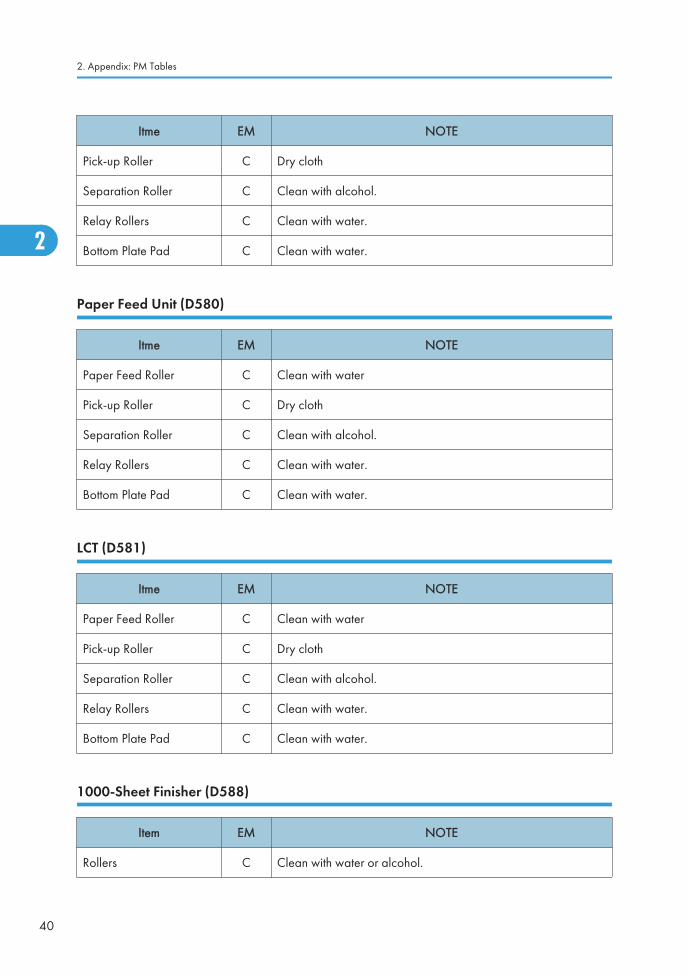
Itme EM NOTE
Pick-up Roller C Dry cloth
Separation Roller C Clean with alcohol.
Relay Rollers C Clean with water.
Bottom Plate Pad C Clean with water.
Paper Feed Unit (D580)
Itme EM NOTE
Paper Feed Roller C Clean with water
Pick-up Roller C Dry cloth
Separation Roller C Clean with alcohol.
Relay Rollers C Clean with water.
Bottom Plate Pad C Clean with water.
LCT (D581)
Itme EM NOTE
Paper Feed Roller C Clean with water
Pick-up Roller C Dry cloth
Separation Roller C Clean with alcohol.
Relay Rollers C Clean with water.
Bottom Plate Pad C Clean with water.
1000-Sheet Finisher (D588)
Item EM NOTE
Rollers C Clean with water or alcohol.
2. Appendix: PM Tables
40
2

Item EM NOTE
Brush Roller I Replace if necessary.
Discharge Brush C Clean with a dry cloth
Sensors C Blower brush
Jogger Fences I Replace if necessary.
1000-Sheet Booklet Finisher (D589)
Item EM NOTE
Rollers C Damp cloth
Discharge Brush C Dry cloth
Sensors C Blower brush
Punch Kit
Punch Chads C Discard chads.
500-Sheet Finisher (D585)
Item EM NOTE
Rollers C Damp cloth
Discharge Brush C Dry cloth
Sensors C Blower brush
1 Bin Tray (D582)
Item EM NOTE
Rollers C Dry or damp cloth
Copy Tray C Dry or damp cloth
Sensors C Blower brush
PM Table
41
2

Internal Finisher (D586)
Item EM NOTE
Rollers C Clean with water or alcohol.
Sensors C Blower brush
Punch Chads C Discard chads.
Others Yield Parts
The parts mentioned in these tables have a target yield. However, the total copy/print volume made bythe machine will not reach the target yield within the machine’s targeted lifetime if the machine is usedunder the target usage conditions (ACV, color ratio, P/J, and C/O). So, these parts are categorized notas PM parts but as yield parts (EM parts).
Item 600K NOTE
Development Case C
2. Appendix: PM Tables
42
2

3. Appendix: Service Call Conditions
Service Call Conditions
Summary
There are 4 levels of service call conditions.
Level Definition Reset Procedure
A
To prevent damage to the machine, the mainmachine cannot be operated until the SC has beenreset by a service representative (see the notebelow).
Enter SP mode, go into SP5810,press [Execute], turn the mainpower switch off and on.
B
SCs that disable only the features that use thedefective item. Although these SCs are not shown tothe user under normal conditions, they are displayedon the operation panel only when the defectivefeature is selected.
Turn the operation switch or mainswitch off and on.
CThe SC history is updated. The machine can beoperated as usual.
The SC will not be displayed.Only the SC history is updated.
DTurning the main switch off then on resets SCsdisplayed on the operation panel. These are re-displayed if the error occurs again.
Turn the operation switch off andon.
When a Level “D” SC code occurs
When a Level D SC occurs, a screen opens on the operation panel to tell the operator:
• An error occurred
• The job in progress will be erased
• The machine will reboot automatically after approximately 30 seconds.
The operator can wait until the machine reboots automatically or touch “Reset” on the screen to reset themachine immediately and go back to the copy screen.
If the operator does not touch “Reset”
The next message tells the operator that the machine will reset automatically and that the previous jobwas lost and must be started again. After reading the message, the operator touches “Confirm” on thescreen. The next screen shows the number and title of the SC code, and stops until the operator turns themachine off and on.
43
3

If the operator touches “Reset”
If the operator touches "Reset" to bypass the 30-second interval for the machine to reboot, the machinereboots immediately and the operation panel displays the copy screen.
• Do not try to use the operation panel during an automatic reboot. If the Remote Service System is inuse, the SC code is sent immediately to the Service Center
SC Code Classification
The table shows the classification of the SC codes:
Class 1 Section SC Code Detailed section
1XX Scanning100 - Scanner
190 - Unique for a specific model
2XX Laser exposure
200 - Polygon motor
220 - Synchronization control
230 - FGATE signal related
240 - LD control
280 - Unique for a specific model
290 - Shutter
3XX Image development 1
300 - Charge
330 - Drum potential
350 - Development
380 - Unique for a specific model
3. Appendix: Service Call Conditions
44
3

Class 1 Section SC Code Detailed section
4XX Image development 2
400 - Image transfer
420 - Paper separation
430 - Cleaning
440 - Around drum
460 - Unit
480 - Others
5XX Paper feed / Fusing
500 - Paper feed
515 - Duplex
520 - Paper transport
5XX Paper feed / Fusing
530 - Fan motor
540 - Fusing
560 - Others
570 - Unique for a specific model
6XX Communication
600 - Electrical counters
620 - Mechanical counters
630 - Account control
640 - CSS
650 - Network
670 - Internal data processing
680 - Unique for a specific model
7XX Peripherals
700 - Original handling
720 - Two-tray finisher
740 - Booklet finisher
Service Call Conditions
45
3

Class 1 Section SC Code Detailed section
8XX Controller
800 - Error after ready condition
820 - Diagnostics error
860 - Hard disk
880 - Unique for a specific model
9XX Others
900 - Counter
920 - Memory
990 - Others
SC1xx: Scanning
No. Type Details (Symptom, Possible Cause, Troubleshooting Procedures)
101 D
Exposure lamp error
The standard white level could not be set properly when scanning the white plateduring automatic white level adjustment.
• White plate dirty
• Spurious electrical noise on power supply line
• Exposure lamp connection loose, broken, defective
• Exposure lamp defective
• High voltage power supply (power pack) harness loose, broken, defective
• SBU defective
• BCU defective
• SIO defective
1. Check and clean the scanner mirror(s) and scanner lens.
2. Check and clean the shading plate.
3. Replace the exposure lamp.
4. Replace the scanner mirror(s) or scanner lens.
5. Replace the SBU board.
6. Replace the BCU board.
7. Replace the SIO board.
3. Appendix: Service Call Conditions
46
3

No. Type Details (Symptom, Possible Cause, Troubleshooting Procedures)
120 D
Scanner home position error 1
The scanner home position sensor does not detect the "OFF" condition duringoperation.
121 DScanner home position error 2
The scanner HP sensor did not turn on during scanner initialization or copying.
- -
• Scanner motor driver defective
• Scanner motor defective
• Harness between SIO board and scanner motor disconnected
• Scanner HP sensor defective
• Harness between SIO and HP sensor disconnected
1. Check the cable connection between the SIO board and scanner motor.
2. Check the cable connection between the SIO and HP sensor.
3. Replace the scanner motor.
4. Replace the HP sensor.
No. Type Details (Symptom, Possible Cause, Troubleshooting Procedures)
141 D
Black level correction error
Black level correction could not be set properly during automatic adjustment.
• Harnesses at the SBU, IPU, BCU loose, broken, defective.
• SBU defective
• IPU defective
• BCU defective
1. Check the cable connection
2. Replace the SBU.
3. Replace the IPU.
4. Replace the BCU.
Service Call Conditions
47
3

No. Type Details (Symptom, Possible Cause, Troubleshooting Procedures)
142 D
White level correction error
White level correction could not be set properly during automatic adjustment.
• Harnesses at SBU, IPU, BCU loose, broken, defective
• Spurious electrical noise on power supply line
• White plate dirty or missing
• Anti-condensation heater (option) in scanner unit not operating
• Exposure lamp harness, loose, broken, defective
• Exposure lamp defective
• SBU defective
• IPU defective
• BCU defective
• SIO Defective
1. Clean the exposure glass, white plate, mirrors, and lens.
2. Check if the exposure lamp is lit during initialization.
3. Check the harness connection between SBU, BCU and IPU.
4. Check the anti-condensation heater (option) is installed correctly.
5. Replace the exposure lamp.
6. Replace the SBU board.
7. Replace the IPU board.
8. Replace the BCU board.
9. Replace the SIO board.
3. Appendix: Service Call Conditions
48
3

No. Type Details (Symptom, Possible Cause, Troubleshooting Procedures)
144 D
SBU communication error
Connection to the SBU could not be confirmed, possibly due to a defect in theBCU detection port.
• Harness connection at IPU, BCU, SBU loose, broken, defective
• Spurious electrical noise on power supply line
• IPU defective
• BCU defective
• SBU defective
1. Replace the harness.
2. Replace the IPU.
3. Replace the SBU.
4. Replace the BCU.
No. Type Details (Symptom, Possible Cause, Troubleshooting Procedures)
161 D IPU error
001 D
The error result of self-diagnostic by the ASIC on the BCU is detected.
• Defective BCU
• Defective connection between BCU and SBU
1. Check the connection between BCU and SBU.
2. Replace the BCU.
002 D
The machine detects an error during an access to the Ri.
• Defective BCU board
Replace the BCU board.
Service Call Conditions
49
3

No. Type Details (Symptom, Possible Cause, Troubleshooting Procedures)
165 D
Copy Data Security Unit error
• The copy data security board is not detected when the copy data securityfunction is set "ON" with the initial setting.
• A device check error occurs when the copy data security function is set "ON"with the initial setting.
• Incorrect installation of the copy data security board
• Defective copy data security board
1. Reinstall the copy data security board.
2. Replace the copy data security board.
No. Type Details (Symptom, Possible Cause, Troubleshooting Procedures)
195 D
Serial Number Mismatch
• Serial number stored in the memory does not have the correct code.
• NVRAM defective
• BCU replaced without original NVRAM
1. Check the serial number with SP5-811-002.
2. If the stored serial number is incorrect, contact your supervisor.
SC 2xx: Exposure
No. Type Details (Symptom, Possible Cause, Troubleshooting Procedures)
202 D
Polygon motor error 1: ON timeout
The polygon mirror motor did not reach the targeted operating speed within 10sec. after turning on or changing speed
203 D
Polygon motor error 1: OFF timeout
The polygon mirror motor did not leave READY status within 3 sec. after polygonmotor switched off.
3. Appendix: Service Call Conditions
50
3

No. Type Details (Symptom, Possible Cause, Troubleshooting Procedures)
204 DPolygon motor error 1: XSCRDY signal error
The XSCRDY signal remained HIGH for 200 ms while the LD unit was firing.
- -
• Polygon motor/driver board harness loose or broken
• Polygon motor/driver board defective
• Laser optic unit defective
• IPU defective
1. Replace the polygon motor.
2. Replace the laser optics housing unit.
3. Replace the harness.
4. Replace the IPU.
No. Type Details (Symptom, Possible Cause, Troubleshooting Procedures)
220 D
Laser synchronization detection error: LD0
The laser synchronizing detection signal for the start position of the LD was notoutput for two sec. after LDB unit turned on with the polygon motor rotatingnormally.
• Laser synchronizing detection board harness loose or broken.
• Laser synchronization detection board defective
• LDB unit defective
• IPU defective
1. Check the connectors.
2. Replace the laser-synchronizing detector.
3. Replace the LDB.
4. Replace the IPU.
No. Type Details (Symptom, Possible Cause, Troubleshooting Procedures)
230 D
FGATE ON error
The FGATE signal did not assert within the prescribed time. (The BCU generates theFGATE signal and sends it to the LD unit when the registration sensor switches on.)
Service Call Conditions
51
3

No. Type Details (Symptom, Possible Cause, Troubleshooting Procedures)
231 D
FGATE OFF error
The FGATE signal did not go off within the prescribed time. (The BCU generatesthe FGATE signal and sends it to the LD unit when the registration sensor switcheson.)
• BCU, Controller board harness loose or broken
• BCU defective
• Controller board defective
1. Check the connection between the controller board and the BCU.
2. Replace the BCU.
3. Replace the controller board.
No. Type Details (Symptom, Possible Cause, Troubleshooting Procedures)
240 C
LD error
The IPU detected a problem at the LD unit.
• LD unit harness broken, defective
• BCU harness broken defective
• LD unit defective
• BCU defective
1. Replace the harness of the LD.
2. Replace the laser optics housing unit.
3. Replace the harness of the BCU.
4. Replace the BCU.
3. Appendix: Service Call Conditions
52
3
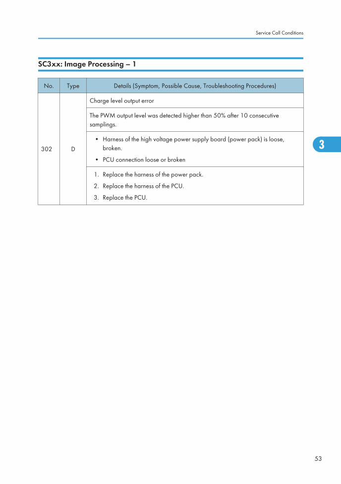
SC3xx: Image Processing – 1
No. Type Details (Symptom, Possible Cause, Troubleshooting Procedures)
302 D
Charge level output error
The PWM output level was detected higher than 50% after 10 consecutivesamplings.
• Harness of the high voltage power supply board (power pack) is loose,broken.
• PCU connection loose or broken
1. Replace the harness of the power pack.
2. Replace the harness of the PCU.
3. Replace the PCU.
Service Call Conditions
53
3

No. Type Details (Symptom, Possible Cause, Troubleshooting Procedures)
355 C
ID sensor error
• One of the following conditions occurred when the ID sensor pattern wascalibrated during printing:
Vsp > 2.5V
Vsg < 2.5V
Vsp = 0V
Vsg = 0V
• The following conditions occurred simultaneously when the ID sensor patternwas calibrated during printing:
Vsg = 5V
PWM = 0 (LED current drop)
• Error occurred during automatic adjustment of Vsg:
Vsg output did not attain 4V, even with PWM = 1023 (maximum current forLED)
Vsg output was greater than 4V, even with PWM=1 (no current for the LED)
• ID sensor dirty or defective
• ID sensor harness disconnected, or connector damaged
• BCU defective
• High voltage power supply board (power pack) defective
• Scanning system or image creation system malfunction
1. Replace the ID sensor harness.
2. Replace the ID sensor.
3. Replace the harness of the high voltage power supply board (power pack).
4. Replace the harness of the BCU.
5. Replace the BCU.
No. Type Details (Symptom, Possible Cause, Troubleshooting Procedures)
389 C
TD sensor error 1
TD sensor output was less than 0.5V, or more than 0.5V 10 times in succession. Ifthe fax unit is installed, this SC is issued immediately. If the fax unit is not installed,this SC is issued after the prescribed number of copies has printed.
3. Appendix: Service Call Conditions
54
3

No. Type Details (Symptom, Possible Cause, Troubleshooting Procedures)
390 D
TD sensor error 2
The TD sensor outputs less than 0.5V or more than 4.0V 10 times consecutivelyduring copying.
Note: If the fax option is installed, this SC is issued immediately.
If the fax option is not installed, this SC is issued after the prescribed number ofpages is copied.
• TD sensor abnormal
• Poor connection of the PCU
1. Replace the TD sensor.
2. Replace the harness of PCU.
No. Type Details (Symptom, Possible Cause, Troubleshooting Procedures)
391 D
Development bias leak
The PWM output level was detected higher than 50% after 10 consecutivesamplings.
• High voltage power supply board (power pack) harness loose, broken.
• PCU connection loose or broken
1. Replace the harness of the high voltage power supply board (power pack).
2. Replace the harness of the PCU.
Service Call Conditions
55
3

No. Type Details (Symptom, Possible Cause, Troubleshooting Procedures)
392 B
TD sensor initial setting error
Initialization of the new PCU unit failed (the drum and development roller did notstart rotating)
• ID sensor harness loose, broken
• TD sensor harness loose, broken
• ID sensor defective
• TD sensor defective
1. Replace the harness of the ID sensor.
2. Replace the the ID sensor.
3. Replace the harness of the TD sensor.
4. Replace the TD sensor.
SC4xx: Image Processing - 3
No. Type Details (Symptom, Possible Cause, Troubleshooting Procedures)
401 D
Transfer roller leak error 1
A transfer roller current leak signal wad detected. (The current feedback signal forthe transfer roller was not detected within the correct time.)
• High voltage supply board set incorrectly or defective
• Transfer roller set incorrectly or damaged
• Transfer unit set incorrectly
1. Check the high voltage supply board is set correctly.
2. Check the harness of the high voltage supply board.
3. Replace the high voltage supply board.
4. Check the transfer roller is set correctly.
5. Replace the transfer roller.
6. Check the transfer unit is set correctly.
3. Appendix: Service Call Conditions
56
3

No. Type Details (Symptom, Possible Cause, Troubleshooting Procedures)
402 D
Transfer roller leak error 2
A transfer roller current leak signal is detected. The current feedback signal for thetransfer roller is not detected within the correct time.
• Transfer roller set incorrectly or damaged
• High voltage supply board set incorrectly or defective
1. Check the high voltage supply board is set correctly.
2. Check the harness of the high voltage supply board.
3. Replace the high voltage supply board.
4. Check the transfer roller is set correctly.
5. Replace the transfer roller.
No. Type Details (Symptom, Possible Cause, Troubleshooting Procedures)
411 D
Separation bias leak error
A separation bias leak signal was detected.
• High voltage supply board defective
• Discharge plate defective
1. Check the harness of the high voltage supply board.
2. Replace the high voltage supply board.
3. Replace the discharge plate.
No. Type Details (Symptom, Possible Cause, Troubleshooting Procedures)
490 D
Toner supply motor leak error r
More than 1 ampere supplied to the toner supply motor for longer than 200 ms.
• Toner supply motor defective
1. Replace the toner transport motor.
Service Call Conditions
57
3

SC5xx: Paper Feed and Fusing
No. Type Details (Symptom, Possible Cause, Troubleshooting Procedures)
500 D
Main motor lock
The machine detected motor lock (motor is not operating correctly)
• An obstruction has blocked operation of the main motor
• Main motor harness loose or broken
• Main motor or main motor driver board defective
• Overload on the main motor
1. Replace the harness of the main motor.
2. Replace the motor.
3. Replace the main motor driver board.
4. Check for the blockages in the main motor mechanism.
No. Type Details (Symptom, Possible Cause, Troubleshooting Procedures)
501 B Paper Tray 1 error
502 B Paper Tray 2 error
- -
• When the tray lift motor rotates counterclockwise, (if the upper limit is notdetected within 10 seconds), the machine asks the user to reset the tray.
• When the tray lift motor rotates clockwise, (if the upper limit is not detectedwithin 1.5 seconds), the machine asks the user to reset the tray.
If one of these conditions occurs three consecutive times, the SC is generated.
• Disconnected or defective paper lift sensor
• Disconnected or defective tray lift motor
• Defective bottom plate lift mechanism
• Too much paper in the tray
• Defective IOB
1. Check if the paper is not loaded too much.
2. Check if the bottom plate smoothly moves up and down manually.
3. Check and/or replace the tray lift motor/ paper lift sensor.
4. Replace the IOB.
3. Appendix: Service Call Conditions
58
3

No. Type Details (Symptom, Possible Cause, Troubleshooting Procedures)
503 B
Tray 3 error (Paper Feed Unit or LCT)
This SC is generated if the following condition occurs 3 consecutive times.
For the paper feed unit:
• When the tray lowers, the tray lift sensor does not go off within 15 sec.
For the LCT:
• When the main switch is turned on or when the LCT is set, if the end fence isnot in the home position (home position sensor ON), the tray lift motor stops.
• If the upper limit does not go off for 8 seconds even the tray lift motor turns onto lower the tray after the upper limit has been detected at power on.
For the paper feed unit:
• Defective tray lift motor or connector disconnection
• Defective lift sensor or connector disconnection
For the LCT:
• Defective stack transport clutch or connector disconnection
• Defective tray motor or connector disconnection
• Defective end fence home position sensor or connector disconnection
1. Check the cable connections.
2. Check and/or replace the defective component.
No. Type Details (Symptom, Possible Cause, Troubleshooting Procedures)
504 B
Tray 4 error (3 Tray Paper Feed Unit)
This SC is generated if the following condition occurs 3 consecutive times.
• When the tray lowers, the tray lift sensor does not go off within 1.5 sec.
1. Check the cable connections.
2. Check and/or replace the defective component.
Service Call Conditions
59
3

No. Type Details (Symptom, Possible Cause, Troubleshooting Procedures)
508 B
By-pass bottom plate error
The signal from the by-pass tray HP sensor does not change for 1.0 second afterthe by-pass motor has rotated counterclockwise.
If this condition occurs three consecutive times, the SC is generated.
• Disconnect or defective harness of the by-pass motor
• Defective or disconnected connection for the by-pass motor.
• Defective by-pass motor
• Disconnect or defective harness of the by-pass HP sensor
• Defective or disconnected connection for the by-pass HP sensor.
• Defective by-pass HP sensor
Check the operation of the by-pass motor with SP5804-023.
No operation:
1. Check the harness connection of the by-pass tray and duplex unit.
2. Replace the by-pass motor.
Operation:
Check the operation of the by-pass HP sensor with SP5803-048 while the by-passmotor is rotating.
No change of Bit 0
1. Check the harness connection of the by-pass HP sensor.
2. Replace the by-pass HP sensor.
No. Type Details (Symptom, Possible Cause, Troubleshooting Procedures)
530 D Ventilation fan: front error
531 D Ventilation fan: rear error
3. Appendix: Service Call Conditions
60
3

No. Type Details (Symptom, Possible Cause, Troubleshooting Procedures)
- -
The motor lock signal error is detected for 10 seconds after the motor lock signalwas first detected.
• Defective ventilation fan: front or rear
• Disconnected or defective harness
• Defective DRB
• Defective BCU
1. Check or replace the harness.
2. Replace the ventilation fan: front (SC530) or rear (SC531).
3. Replace the DRB.
4. Replace the BCU.
No. Type Details (Symptom, Possible Cause, Troubleshooting Procedures)
532 D
Laser unit fan error
The motor lock signal error is detected for 10 seconds after the motor lock signalwas first detected.
• Defective laser unit fan
• Disconnected or defective harness
• Defective drive board
• Defective BCU
1. Replace the laser unit fan.
2. Check the harness of the laser unit fan.
3. Replace the harness of the laser unit fan.
4. Replace the drive board.
5. Replace the BCU.
Service Call Conditions
61
3

No. Type Details (Symptom, Possible Cause, Troubleshooting Procedures)
541 A
Fusing thermistor open (center)
The temperature of the hot roller remained below 0oC for 5 sec at the center of thehot roller.
• Fusing thermistor out of its position because of incorrect installation
• Fusing thermistor disconnected or defective
• Power supply not within rated range (15% or more below rating)
1. Check the fusing thermistor is set correctly.
2. Replace the fusing thermistor.
3. Check the power supply source.
No. Type Details (Symptom, Possible Cause, Troubleshooting Procedures)
542 A
Fusing temperature warm-up error (center)
• The fusing temperature did not reach the standby temperature within 20 sec.at the center of the hot roller after the main switch turned on.
• Fusing thermistor defective or out of position
• Fusing lamp disconnected
• Thermistor defective
• Fusing lamp defective
1. Check the fusing thermistor is set correctly.
2. Replace the fusing thermistor.
3. Check the fusing lamp is connected.
4. Replace the fusing lamp.
3. Appendix: Service Call Conditions
62
3

No. Type Details (Symptom, Possible Cause, Troubleshooting Procedures)
543 A
Fusing overheat error 1 (center)
The fusing thermistor detected a fusing temperature over 230°C for 5 sec. at thecenter of the hot roller.
• TRIAC short on PSU (PSU defective)
• BCU board defective
• Fusing thermistor defective
1. Replace the PSU.
2. Replace the BCU board.
3. Replace the thermistor.
No. Type Details (Symptom, Possible Cause, Troubleshooting Procedures)
544 A
Fusing overheat error 2 (center)
A fusing temperature over 250°C is detected at the center of the hot roller by thefusing temperature monitor circuit in the BCU board.
The power was interrupted for more than 0.3 sec.
• TRIAC short on PSU (PSU defective)
• BCU board defective
• Fusing thermistor defective
• Power supply voltage unstable
1. Replace the PSU.
2. Replace the BCU board.
3. Replace the thermistor.
4. Check the power supply source.
Service Call Conditions
63
3

No. Type Details (Symptom, Possible Cause, Troubleshooting Procedures)
545 A
Fusing overheat error 3 (center)
After warmup, the center of the hot roller attained full operating temperature andmaintained this temperature for 10 sec. without the hot roller rotating.
• Center hot roller thermistor installed incorrectly, disconnected.
• Center hot roller thermistor defective
1. Check the hot roller thermistor is set correctly.
2. Replace the hot roller thermistor.
No. Type Details (Symptom, Possible Cause, Troubleshooting Procedures)
547 D
• The zero cross signal is detected for 0.05 seconds three times even thoughthe heater relay is off when turning on the main power.
• The zero cross signal is not detected for 2 seconds even though the heaterrelay is on after turning on the main power or closing the front door.
• Defective fusing lamp relay
• Defective fusing lamp relay circuit
• Unstable power supply
1. Replace the fusing lamp relay.
2. Check the power supply source.
No. Type Details (Symptom, Possible Cause, Troubleshooting Procedures)
551 A
Fusing thermistor open (end)
The temperature of the hot roller remained below 0oC for 5 sec. at the end of thehot roller.
• Fusing thermistor out of its position because of incorrect installation
• Fusing thermistor disconnected or defective
• Power supply not within rated range (15% or more below rating)
1. Check the fusing thermistor is set correctly.
2. Replace the fusing thermistor.
3. Check the power supply source.
3. Appendix: Service Call Conditions
64
3

No. Type Details (Symptom, Possible Cause, Troubleshooting Procedures)
552 A
Fusing temperature warm-up error (end)
The fusing temperature did not reach the standby temperature within 20 sec. at thecenter of the hot roller after the main switch turned on.
• Fusing thermistor defective or out of position
• Fusing lamp disconnected
• Thermistor defective
• Fusing lamp defective
1. Check the fusing thermistor is set correctly.
2. Check the fusing lamp is connected correctly.
3. Replace the fusing thermistor.
4. Replace the fusing lamp.
No. Type Details (Symptom, Possible Cause, Troubleshooting Procedures)
553 A
Fusing overheat error 1 (end)
The fusing thermistor detected a fusing temperature over 230°C for 5 sec. at thecenter of the hot roller.
• TRIAC short on PSU (PSU defective)
• BCU board defective
• Fusing thermistor defective
1. Replace the PSU.
2. Replace the BCU board.
3. Replace the thermistor.
Service Call Conditions
65
3

No. Type Details (Symptom, Possible Cause, Troubleshooting Procedures)
554 A
Fusing overheat error 2 (end)
A fusing temperature over 250°C is detected at the center of the hot roller by thefusing temperature monitor circuit in the BCU board.
The power was interrupted for more than 0.3 sec.
• TRIAC short on PSU (PSU defective)
• BCU board defective
• Fusing thermistor defective
• Power supply voltage unstable
1. Replace the PSU.
2. Replace the BCU board.
3. Replace the thermistor.
4. Check the power supply source.
No. Type Details (Symptom, Possible Cause, Troubleshooting Procedures)
555 A
Fusing overheat error 3 (end)
After warmup, the center of the hot roller attained full operating temperature andmaintained this temperature for 10 sec. without the hot roller rotating.
• Center hot roller thermistor installed incorrectly, disconnected.
• Center hot roller thermistor defective
1. Check the hot roller thermistor is set correctly.
2. Replace the hot roller thermistor.
No. Type Details (Symptom, Possible Cause, Troubleshooting Procedures)
557 C
Zero cross waveform signal error
The waveform of the zero cross signal was detected out of range.
• Electrical noise on the power supply line
Check the power supply source.
3. Appendix: Service Call Conditions
66
3

No. Type Details (Symptom, Possible Cause, Troubleshooting Procedures)
559 A
Consecutive fusing unit paper jams
Three consecutive paper jams occurred in the fusing unit.
The paper jam counter for the fusing unit reaches 3 times. The paper jam counterclears after the paper feeds correctly.
Note: This SC is issued only if SP1159 is set to "1".
• Paper jam in the fusing unit.
1. Remove the paper jam in the fusing unit.
2. Make sure that the paper path in the fusing unit is clear.
No. Type Details (Symptom, Possible Cause, Troubleshooting Procedures)
590 D
Exhaust fan motor error
The CPU detects an exhaust fan lock signal consecutively 200 ms.
• Poor connection of the exhaust fan motor
• Too much load on the motor drive
1. Check the connection of the exhaust fan motor.
2. Check for blockages in the motor drive mechanism.
Service Call Conditions
67
3
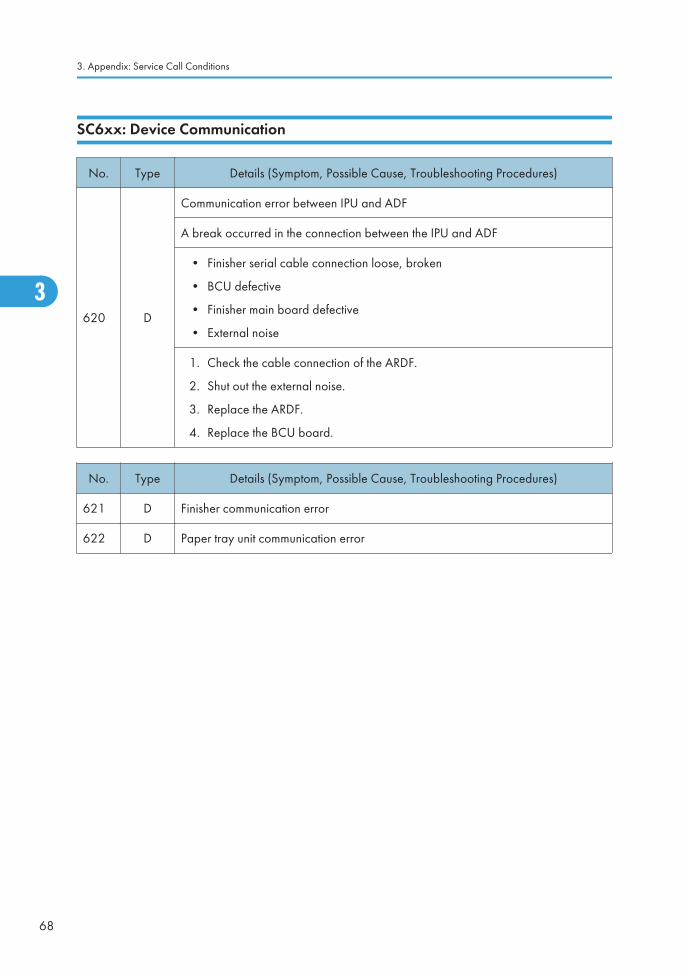
SC6xx: Device Communication
No. Type Details (Symptom, Possible Cause, Troubleshooting Procedures)
620 D
Communication error between IPU and ADF
A break occurred in the connection between the IPU and ADF
• Finisher serial cable connection loose, broken
• BCU defective
• Finisher main board defective
• External noise
1. Check the cable connection of the ARDF.
2. Shut out the external noise.
3. Replace the ARDF.
4. Replace the BCU board.
No. Type Details (Symptom, Possible Cause, Troubleshooting Procedures)
621 D Finisher communication error
622 D Paper tray unit communication error
3. Appendix: Service Call Conditions
68
3

No. Type Details (Symptom, Possible Cause, Troubleshooting Procedures)
- -
While the IOB communicates with an optional unit, an SC code is displayed if oneof following conditions occurs.
• The IOB receives the break signal which is generated by the peripherals onlyjust after the main switch is turned on.
• When the IOB does not receive an OK signal from a peripheral 100ms aftersending a command to it. The IOB resends the command. The IOB does notreceive an OK signal after sending the command 3 times.
• Cable problems
• IOB problems
• BCU problems
• PSU problems in the machine
• Main board problems in the peripherals
1. Check if the cables of peripherals are correctly connected.
2. Replace the PSU if no power is supplied to peripherals.
3. Replace the IOB or main board of peripherals.
4. Replace the BCU.
No. Type Details (Symptom, Possible Cause, Troubleshooting Procedures)
632 B
Counter device error 1
After 3 attempts to send a data frame to the optional counter device via the serialcommunication line, no ACK signal was received within 100 ms.
• Serial line between the optional counter device, the relay board and copiercontrol board is disconnected or damaged
• Make sure that SP5113 is set to enable the optional counter device.
Check the connection between the main machine and optional counter device.
Service Call Conditions
69
3

No. Type Details (Symptom, Possible Cause, Troubleshooting Procedures)
633 B
Key/card counter device error 2
During communication with the device, the MCU received a break (Low) signal.
• Serial line from the device to the main machine is unstable, disconnected, ordefective
1. Check if the setting of the SP5113 is correctly set.
2. Check the connection between the main machine and optional counterdevice.
No. Type Details (Symptom, Possible Cause, Troubleshooting Procedures)
634 B
Key/card counter device error 3
The backup battery of the counter device RAM is low.
• RAM backup battery exhausted
• Counter device defective
Replace the counter device.
No. Type Details (Symptom, Possible Cause, Troubleshooting Procedures)
635 B
Key/card counter device error 4
After installation of the device a message alerts user to a battery voltage abnormalerror.
• Device control board defective
• Device control board backup battery defective
Replace the counter device.
3. Appendix: Service Call Conditions
70
3

No. Type Details (Symptom, Possible Cause, Troubleshooting Procedures)
636 D
OSM User Code File Error
The correct "usercode" file could not be found in the root folder of the SD cardbecause the file is not present, or the existing file is corrupted or the wrong typefile.
• Make sure the eccm.mod file is in the root folder of the SD card.
Note: The usercode files are created with the User Setting Tool "IDissuer.exe".
Check the eccm.mod file is in the root folder of the SD card.
No. Type Details (Symptom, Possible Cause, Troubleshooting Procedures)
641 D
Engine-Controller Communication Error: Non-Response
There was no response to a frame sent from the controller board to the engine.
Turn the machine power off/on.
No. Type Details (Symptom, Possible Cause, Troubleshooting Procedures)
650 CTL Communication error of the remote service modem (Cumin-M)
-001 -
Authentication error
The authentication for the Cumin-M failed at dial up connection.
• Incorrect SP settings
• Disconnected telephone line
• Disconnected modem board
Check and set the correct user name (SP5816-156) and password(SP5816-157).
-004 -
Incorrect modem setting
Dial up fails due to the incorrect modem setting.
Same as -001
Check and set the correct AT command (SP5819-160).
Service Call Conditions
71
3

No. Type Details (Symptom, Possible Cause, Troubleshooting Procedures)
-005 -
Communication line error
The supplied voltage is not sufficient due to the defective communication line ordefective connection.
Same as -001
Consult with the user's local telephone company.
-011 -
Incorrect network setting
Both the NIC and Cumin-M are activated at the same time.
Same as -001
Disable the NIC with SP5985-1.
-012 -
Modem board error
The modem board does not work properly even though the setting of the modemboard is installed with a dial up connection.
Same as -001
1. Install the modem board.
2. Replace the modem board.
No. Type Details (Symptom, Possible Cause, Troubleshooting Procedures)
651 C
Incorrect dial up connection
-001: Program parameter error
-002: Program execution error
An unexpected error occurs when the modem (Embedded RCG-M) tries to call thecenter with a dial up connection.
• Caused by a software bug
No action required because this SC does not interfere with operation of themachine.
3. Appendix: Service Call Conditions
72
3

No. Type Details (Symptom, Possible Cause, Troubleshooting Procedures)
652 C
ID2 mismatching
ID2 for @Remote certification is mismatching between the controller board andNVRAM.
• Used controller board installed
• Used NVRAM installed
1. Install the correct controller board or new controller board.
2. Install the correct NVRAM or new NVRAM.
No. Type Details (Symptom, Possible Cause, Troubleshooting Procedures)
653 B
ID2 error
ID2 stored in the NVRAM is incorrect.
• Used NVRAM installed
Clear the ID2 in the NVRAM, and then input a correct ID2.
Service Call Conditions
73
3

No. Type Details (Symptom, Possible Cause, Troubleshooting Procedures)
669 D
EEPROM Communication Error
[1] Open communication error: ID error
[2] Open communication error: Channel error
[3] Open communication error: Device error
[4] Open communication error: Communication failed error
[5] Open communication error: Communication time error
[6] Open communication error: Communication suspended error
[7] Open communication error: Buffer full error
[8] Close communication error: No error code
[9] Close communication error: ID error
[10] Close communication error: No error code
[11] Data write error: ID error
[12] Data write error: Channel error
[13] Data write error: Device error
[14] Data write error: Communication suspended error
[15] Data write error: Communication time over error
[16] Data write error: Communication suspended error
3. Appendix: Service Call Conditions
74
3

No. Type Details (Symptom, Possible Cause, Troubleshooting Procedures)
[17] Data write error: Buffer full error
[18] Data write error: No error code
[19] Data read error: ID error
[20] Data read error: Channel error
[21] Data read error: Device error
[22] Data read error: Communication failed error
[23] Data read error: Communication time over error
[24] Data read error: Communication suspended error
[25] Data read error: Buffer full error
The machine failed to detect a match between the read/write data for theEEPROM on the BCU after 3 attempts.
• EEPROM installed incorrectly
• EEPROM defective. Turn the machine power off/on after replacing theEEPROM.
• BCU defective.
1. Install the EEPROM correctly.
2. Replace the EEPROM.
3. Replace the BCU.
Service Call Conditions
75
3
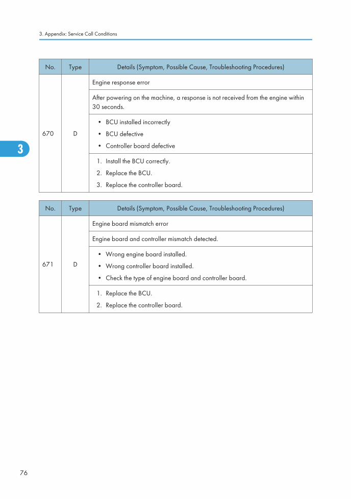
No. Type Details (Symptom, Possible Cause, Troubleshooting Procedures)
670 D
Engine response error
After powering on the machine, a response is not received from the engine within30 seconds.
• BCU installed incorrectly
• BCU defective
• Controller board defective
1. Install the BCU correctly.
2. Replace the BCU.
3. Replace the controller board.
No. Type Details (Symptom, Possible Cause, Troubleshooting Procedures)
671 D
Engine board mismatch error
Engine board and controller mismatch detected.
• Wrong engine board installed.
• Wrong controller board installed.
• Check the type of engine board and controller board.
1. Replace the BCU.
2. Replace the controller board.
3. Appendix: Service Call Conditions
76
3

No. Type Details (Symptom, Possible Cause, Troubleshooting Procedures)
672 D
Controller-to-operation panel communication error at startup
After powering on the machine, the communication circuit between the controllerand the operation panel is not opened, or communication with controller isinterrupted after a normal startup.
• Controller stalled
• Controller board installed incorrectly
• Controller board defective
• Operation panel connector loose or defective
1. Check the harness connection.
2. Replace the controller board.
No. Type Details (Symptom, Possible Cause, Troubleshooting Procedures)
674 DTransmission error in controller board
Video transmission error is detected in the controller board.
-01
M2P error
M2P error is occurred during transmitting the video data to the ASIC.
• Defective Controller Board
1. Turn the main switch off and on.
2. Replace the controller board.
-02
PCI error
ASIC could not access to the PCI.
• Defective Controller Board
1. Turn the main switch off and on.
2. Replace the controller board.
Service Call Conditions
77
3

No. Type Details (Symptom, Possible Cause, Troubleshooting Procedures)
687 D
Memory address (PER) command error
The BCU did not receive a memory address command from the controller with theprescribed time once the paper reached the registration sensor.
• Harness connection at BCU, Controller board loose or broken
• Defective HDD
• Defective BCU
• Defective Controller Board
1. Check if the controller board is firmly connected to the BCU.
2. Replace the controller board.
3. Replace the HDD
4. Replace the BCU.
No. Type Details (Symptom, Possible Cause, Troubleshooting Procedures)
690 D
GAVD communication error
• The I2C bus device ID is not identified during initialization.
• A device-status error occurs during I2C bus communication.
• The I2C bus communication is not established due to an error other than abuffer shortage.
• Loose connection
• Defective BCU
• Defective LD controller board
1. Turn the main switch off and on.
2. Check the cable connection.
3. Replace the laser optics-housing unit.
4. Replace the BCU board.
3. Appendix: Service Call Conditions
78
3

SC7xx: Peripherals
No. Type Details (Symptom, Possible Cause, Troubleshooting Procedures)
720 B
Upper transport motor error
The upper transport motor in the finisher is not operating.
• Upper transport motor drive is obstructed (jammed paper, paper scraps, etc.)
• The motor harness loose or broken
• Upper transport motor defective
1. Check for blockages in the upper transport motor mechanism.
2. Replace the upper transport motor.
3. Replace the finisher main board.
No. Type Details (Symptom, Possible Cause, Troubleshooting Procedures)
721 B
Front fence motor error
The jogger fence motor in the finisher is not operating.
• Jogger motor drive is obstructed (jammed paper, paper scraps, etc.)
• The motor harness loose or broken
• Jogger fence HP sensor dirty, loose, defective
• Jogger fence motor defective
1. Check the connections and cables for the components mentioned above.
2. Check for blockages in the jogger fence motor mechanism.
3. Replace the jogger fence HP sensor and/or jogger motor.
4. Replace the finisher main board.
Service Call Conditions
79
3

No. Type Details (Symptom, Possible Cause, Troubleshooting Procedures)
723 B
Feed-out belt motor error
The feed-out belt did not return to the home position within the prescribed time.
• Feed-out belt motor drive is obstructed (jammed paper, paper scraps, etc.)
• Motor harness loose or broken
• Feed-out belt HP sensor dirty, disconnected, broken
• Motor defective
1. Check the connections and cables for the components mentioned above.
2. Check for blockages in the feed-out belt motor mechanism.
3. Replace the feed-out belt HP sensor and/or feed-out motor.
4. Replace the finisher main board.
No. Type Details (Symptom, Possible Cause, Troubleshooting Procedures)
725 B
Finisher exit guide plate motor error
The exit guide plate HP sensor did not activate within the prescribed time after theexit guide plate motor turned on.
• Finisher exit guide plate motor drive is obstructed (jammed paper, paperscraps, etc.)
• Exit guide plate motor harness loose, broken
• Exit guide plate HP sensor harness loose, broken
• Exit guide plate motor defective
• Exit guide plate HP sensor defective
1. Check the connections and cables for the components mentioned above.
2. Check for blockages in the exit guide plate motor mechanism.
3. Replace the exit guide plate position sensor and/or exit guide plate motor.
4. Replace the finisher main board.
3. Appendix: Service Call Conditions
80
3

No. Type Details (Symptom, Possible Cause, Troubleshooting Procedures)
730 B
Shift tray motor error
The shift tray motor in the 1000-sheet finisher is not operating.
• Shift motor drive is obstructed (jammed paper, paper scraps, etc.)
• Shift motor harness loose, broken
• Shift tray HP sensor harness loose, broken
• Shift motor defective
• Shit tray HP sensor defective
1. Check the connections and cables for the components mentioned above.
2. Check for blockages in shift tray motor mechanism.
3. Replace the shift tray HP sensor and/or shift tray motor.
4. Replace the finisher main board.
No. Type Details (Symptom, Possible Cause, Troubleshooting Procedures)
731 B
Exit motor error
The exit motor in the finisher is not operating.
• Exit motor drive is obstructed (jammed paper, paper scraps, etc.)
• The motor harness loose or broken
• Exit motor defective
1. Check for blockages in the exit motor mechanism.
2. Replace the exit motor.
3. Replace the finisher main board.
Service Call Conditions
81
3

No. Type Details (Symptom, Possible Cause, Troubleshooting Procedures)
740 B
Corner stapler motor error
The 1st detection failure issues a jam error, and the 2nd failure issues this SC code.
For 1000-sheet (booklet) finisher
• The stapler motor does not switch off within the prescribed time afteroperating.
• The HP sensor of the staple unit does not detect the home position after thestaple unit moves to its home position.
The HP sensor of the staple unit detects the home position after the staple unitmoves from its home position.
• Staple jam
• Number of sheets in stack exceeds allowed number of sheets for stapling
• Stapler motor obstructed
• Stapler motor defective
1. Check the connections and cables for the components mentioned above.
2. Replace the HP sensor and/or stapler motor.
3. Replace the finisher main board.
3. Appendix: Service Call Conditions
82
3

No. Type Details (Symptom, Possible Cause, Troubleshooting Procedures)
742 B
Stapler movement motor
The 1st detection failure issues a jam error, and the 2nd failure issues this SC code.
For 1000-sheet (booklet) finisher
• The stapler HP sensor is not activated within the specified time after the staplermotor turned on.
• Stapler or motor drive is blocked by obstruction
• Motor harness loose or broken
• Stapler HP sensor harness loose, broken
• Motor defective
• Stapler HP sensor defective
1. Check the connection of the stapler movement motor.
2. Check the connection of the stapler home position sensor.
3. Replace the stapler home position sensor.
4. Replace the stapler movement motor.
No. Type Details (Symptom, Possible Cause, Troubleshooting Procedures)
746 B
Stack feed motor error
The stack feed HP sensor in the 1000-sheet booklet finisher did not detect "ON"twice (once: jam error) within the prescribed time after the stack feed motor turnedon.
-or-
• The stack feed HP sensor did not detect "OFF" twice (once: jam error) for thespecified time after the stack feed motor turned on.
• Motor drive obstructed
• Stack feed motor harness loose, broken
• Stack feed motor defective
1. Check the connections and cables for the stack feed motor and HP sensor.
2. Check for blockages in the stack feed motor mechanism.
3. Replace the stack feed HP sensor and/or stack feed motor
4. Replace the finisher main board.
Service Call Conditions
83
3

No. Type Details (Symptom, Possible Cause, Troubleshooting Procedures)
747 B
Lower transport motor error
The lower transport motor in the finisher is not operating.
• Lower transport motor drive is obstructed (jammed paper, paper scraps, etc.)
• The motor harness loose or broken
• Lower transport motor defective
1. Check for blockages in the upper transport motor mechanism.
2. Replace the upper transport motor.
3. Replace the finisher main board.
No. Type Details (Symptom, Possible Cause, Troubleshooting Procedures)
750 B
Tray lift motor error
The tray lift motor in the 1000-sheet booklet finisher is not operating.
• Motor harness loose, broken
• Motor drive obstructed
• Stack height sensor dirty, harness loose, broken
• Motor defective
• Stack height sensor defective
1. Check the connections to the shift tray motor.
2. Replace the shift tray motor.
3. Check the connections to the stack height sensor.
4. Replace the stack height sensor.
3. Appendix: Service Call Conditions
84
3

No. Type Details (Symptom, Possible Cause, Troubleshooting Procedures)
760 B
Finisher punch motor error (D589)
The punch HP sensor is not activated within the specified time after the punchmotor turned on. The 1st detection failure issues a jam error, and the 2nd failureissues this SC code.
• Punch HP sensor harness loose, broken
• Punch motor harness loose, broken
• Punch motor obstructed
• Punch motor defective
• Punch HP sensor defective
1. Check the connections and cables for the punch motor and HP sensor.
2. Check for blockages in the punch motor mechanism.
3. Replace the punch motor harness.
4. Replace the punch HP sensor and/or punch motor
5. Replace the finisher main board.
No. Type Details (Symptom, Possible Cause, Troubleshooting Procedures)
761 B
Folder plate motor error (D589)
The folder plate in the 1000-sheet booklet finisher moved but was not detected atthe home position within the prescribed time. The 1st detection failure issues a jamerror, and the 2nd failure issues this SC code.
• Folder plate motor drive obstructed
• Folder plate HP sensor harness loose, broken
• Folder plate motor harness loose, broken
• Folder plate motor defective
• Folder plate HP sensor defective
1. Check the connections and cables for the folder plate motor and HP sensor.
2. Check for blockages in the folder plate motor mechanism.
3. Replace the folder plate motor harness.
4. Replace the folder plate HP sensor and/or folder plate motor
5. Replace the finisher main board.
Service Call Conditions
85
3

No. Type Details (Symptom, Possible Cause, Troubleshooting Procedures)
763 B
Punch movement motor error (D589)
The punch unit moved but it was not detected at the home position within theprescribed time. The 1st detection failure issues a jam error, and the 2nd failureissues this SC code.
• Motor harness loose, broken
• Motor drive obstructed
• Motor defective
1. Check the connections to the punch movement motor.
2. Replace the punch movement motor
No. Type Details (Symptom, Possible Cause, Troubleshooting Procedures)
764 B
Paper position slide motor error (D589)
The paper position sensor detected movement of the slide but the slide was notdetected at the home position within the prescribed time. The 1st detection failureissues a jam error, and the 2nd failure issues this SC code.
• Motor harness loose, broken
• Motor drive obstructed
• Motor defective
1. Check the connections to the paper position sensor slide motor.
2. Replace the paper position sensor slide motor.
3. Appendix: Service Call Conditions
86
3

No. Type Details (Symptom, Possible Cause, Troubleshooting Procedures)
765 B
Bottom fence lift motor error (D589)
The bottom fence HP sensor moves but is not detected at the home position withinthe specified time. The 1st detection failure issues a jam error, and the 2nd failureissues this SC code.
• Motor harness loose, broken
• Motor drive obstructed
• Motor defective
1. Check the connections to the bottom fence lift motor.
2. Replace the bottom fence lift motor.
No. Type Details (Symptom, Possible Cause, Troubleshooting Procedures)
766 B
Paper position sensor slide motor error (D589)
The paper position sensor moves but is not detected at the home position within thespecified time. The 1st detection failure issues a jam error, and the 2nd failureissues this SC code.
• Motor harness loose, broken
• Motor drive obstructed
• Motor defective
1. Check the connections to the paper position sensor slide motor.
2. Replace the paper position sensor slide motor.
No. Type Details (Symptom, Possible Cause, Troubleshooting Procedures)
770 B
Shift motor error (D583)
The shift motor HP sensor does not detect any change for 1.86 seconds after theshift motor has turned on at power on or during its operation.
• Defective shift motor
• Defective shift motor HP sensor
1. Check the connections to the shift motor and the shift motor HP sensor.
2. Defective shift motor or the shift motor HP sensor.
Service Call Conditions
87
3

No. Type Details (Symptom, Possible Cause, Troubleshooting Procedures)
791 D
Bridge unit error
The machine recognizes the finisher, but does not recognize the bridge unit.
• Defective connector
• Broken harness
1. Check the connections between the bridge unit and the machine.
2. Install a new bridge unit.
No. Type Details (Symptom, Possible Cause, Troubleshooting Procedures)
792 B
Finisher error
The machine does not recognize the finisher, but recognizes the bridge unit.
• Defective connector
• Defective harness
• Incorrect installation
1. Check the connections between the finisher and the machine.
2. Install a new finisher.
No. Type Details (Symptom, Possible Cause, Troubleshooting Procedures)
793-01
B Front jogger motor error with 1-bin tray (D586)
794-01
D Front jogger motor error without 1-bin tray (D586)
3. Appendix: Service Call Conditions
88
3

No. Type Details (Symptom, Possible Cause, Troubleshooting Procedures)
- -
The machine does not detect a correct signal from the front jogger fence HP sensorwhile the front jogger motor is operating. The 1st detection failure issues a jamerror, and the 2nd failure issues this SC code.
• Defective front jogger motor
• Loosen connection
• Motor overload
• Defective front jogger fence HP sensor
1. Replace the front jogger fence HP sensor.
2. Replace the front jogger motor.
No. Type Details (Symptom, Possible Cause, Troubleshooting Procedures)
793-02
B Rear jogger motor error with 1-bin tray (D586)
794-02
D Rear jogger motor error 1-bin tray (D586)
- -
The machine does not detect a correct signal from the rear jogger fence HP sensorwhile the rear jogger motor is operating. The 1st detection failure issues a jamerror, and the 2nd failure issues this SC code.
• Defective rear jogger motor
• Loosen connection
• Motor overload
• Defective rear jogger fence HP sensor
1. Replace the rear jogger fence HP sensor.
2. Replace the rear jogger motor.
No. Type Details (Symptom, Possible Cause, Troubleshooting Procedures)
793-03
B Pick-up roller contact motor error with 1-bin tray (D586)
794-03
D Pick-up roller contact motor error without 1-bin tray (D586)
Service Call Conditions
89
3

No. Type Details (Symptom, Possible Cause, Troubleshooting Procedures)
- -
The machine does not detect a correct signal from the pick-up roller HP sensorwhile the pick-up roller contact motor is operating. The 1st detection failure issuesa jam error, and the 2nd failure issues this SC code.
• Defective pick-up roller contact motor
• Loosen connection
• Motor overload
• Defective pick-up roller HP sensor
1. Replace the pick-up roller HP sensor.
2. Replace the pick-up roller contact motor.
No. Type Details (Symptom, Possible Cause, Troubleshooting Procedures)
793-04
B Exit guide plate motor error with 1-bin tray (D586)
794-04
D Exit guide plate motor error without 1-bin tray (D586)
- -
The machine does not detect a correct signal from the exit guide plate HP sensorwhile the exit guide plate motor is operating. The 1st detection failure issues a jamerror, and the 2nd failure issues this SC code.
• Defective exit guide plate motor
• Loosen connection
• Motor overload
• Defective exit guide plate HP sensor
1. Replace the exit guide plate HP sensor.
2. Replace the exit guide plate motor.
No. Type Details (Symptom, Possible Cause, Troubleshooting Procedures)
793-05
B Output tray motor error with 1-bin tray (D586)
794-05
D D error without 1-bin tray (D586)
3. Appendix: Service Call Conditions
90
3

No. Type Details (Symptom, Possible Cause, Troubleshooting Procedures)
- -
The machine does not detect a correct signal from the stack height detection leversensor while the output tray motor is operating. The 1st detection failure issues ajam error, and the 2nd failure issues this SC code.
• Defective output tray motor
• Loosen connection
• Motor overload
• Defective stack height detection lever sensor
1. Replace the stack height detection lever sensor.
2. Replace the output tray motor.
No. Type Details (Symptom, Possible Cause, Troubleshooting Procedures)
793-06
B Stack height detection lever motor error with 1-bin tray (D586)
794-06
D Stack height detection lever motor error without 1-bin tray (D586)
- -
The machine does not detect a correct signal from the stack height detection leverHP sensor while the stack height detection lever motor is operating. The 1stdetection failure issues a jam error, and the 2nd failure issues this SC code.
• Defective stack height detection lever motor
• Loosen connection
• Motor overload
• Defective stack height detection lever HP sensor
• Defective stack height detection lever sensor
1. Replace the stack height detection lever sensor.
2. Replace the output tray motor.
No. Type Details (Symptom, Possible Cause, Troubleshooting Procedures)
793-07
B Punch drive motor error with 1-bin tray (D586)
794-07
D Punch drive motor error without 1-bin tray (D586)
Service Call Conditions
91
3

No. Type Details (Symptom, Possible Cause, Troubleshooting Procedures)
- -
The machine does not detect a correct signal from the punch position sensor whilethe punch drive motor is operating. The 1st detection failure issues a jam error, andthe 2nd failure issues this SC code.
• Defective punch drive motor
• Loosen connection
• Motor overload
• Defective punch position sensor
1. Replace the punch position sensor .
2. Replace the punch drive motor.
No. Type Details (Symptom, Possible Cause, Troubleshooting Procedures)
793-08
B Punch movement motor error with 1-bin tray (D586)
794-08
D Punch movement motor error without 1-bin tray (D586)
- -
The machine does not detect a correct signal from the punch position sensor whilethe punch movement motor is operating. The 1st detection failure issues a jamerror, and the 2nd failure issues this SC code.
• Defective punch movement motor
• Loosen connection
• Motor overload
• Defective punch position sensor
1. Replace the punch position sensor.
2. Replace the punch movement motor.
No. Type Details (Symptom, Possible Cause, Troubleshooting Procedures)
793-09
B Paper position sensor unit motor error with 1-bin tray (D586)
794-09
D Paper position sensor unit motor error without 1-bin tray (D586)
3. Appendix: Service Call Conditions
92
3

No. Type Details (Symptom, Possible Cause, Troubleshooting Procedures)
- -
The machine does not detect a correct signal from the paper position detection unitHP sensor while paper position sensor unit motor is operating. The 1st detectionfailure issues a jam error, and the 2nd failure issues this SC code.
• Defective paper position sensor unit motor
• Loosen connection
• Motor overload
• Defective paper position detection unit HP sensor
1. Replace the paper position detection unit HP sensor.
2. Replace the paper position sensor unit motor.
No. Type Details (Symptom, Possible Cause, Troubleshooting Procedures)
793-11
B Stapler unit motor error with 1-bin tray (D586)
794-11
D Stapler unit motor error without 1-bin tray (D586)
- -
The machine does not detect a correct signal from the paper position detection unitHP sensor while the stapler unit motor is operating. The 1st detection failure issuesa jam error, and the 2nd failure issues this SC code.
• Defective paper position sensor unit motor
• Loosen connection
• Motor overload
• Defective paper position detection unit HP sensor
1. Replace the paper position detection unit HP sensor.
2. Replace the paper position sensor unit motor.
No. Type Details (Symptom, Possible Cause, Troubleshooting Procedures)
793-12
B Shift roller motor error with 1-bin tray (D586)
794-12
D Shift roller motor error without 1-bin tray (D586)
Service Call Conditions
93
3

No. Type Details (Symptom, Possible Cause, Troubleshooting Procedures)
- -
The machine does not detect a correct signal from the shift roller HP sensor whilethe shift roller motor is operating. The 1st detection failure issues a jam error, andthe 2nd failure issues this SC code.
• Defective paper position sensor unit motor
• Loosen connection
• Motor overload
• Defective shift roller HP sensor
1. Replace the shift roller HP sensor.
2. Replace the paper position sensor unit motor.
No. Type Details (Symptom, Possible Cause, Troubleshooting Procedures)
798
-01B
Upper limit switch error (D585)
The upper limit switch of the 500-sheet finisher (D585) is pushed due to tray lifterror or some problems.
• Upper limit switch pulled up
• Defective upper limit swtich
1. Check the harness.
2. Check for blockage around the upper limit switch.
3. Replace the upper limit switch.
3. Appendix: Service Call Conditions
94
3

No. Type Details (Symptom, Possible Cause, Troubleshooting Procedures)
798
-02B
Finisher jogger motor error (D585)
The machine does not detect a correct signal from the front jogger fence HP sensorwhile the front jogger motor is operating. The 1st failure issues an original jammessage, and the 2nd failure issues this SC code.
• Jogger HP sensor disconnected, defective
• Jogger motor disconnected, defective
• Jogger motor overloaded due to obstruction
• Finisher main board and jogger motor
1. Check or replace the harness.
2. Check for blockages in the jogger motor mechanism.
3. Replace the jogger HP sensor.
4. Replace the jogger motor.
5. Replace the finisher main board.
No. Type Details (Symptom, Possible Cause, Troubleshooting Procedures)
798
-03B
Rear fence motor error (D585)
The machine does not detect a correct signal from the rear jogger fence HP sensorwhile the rear jogger motor is operating. The 1st detection failure issues a jamerror, and the 2nd failure issues this SC code.
• Rear jogger motor drive is obstructed (jammed paper, paper scraps, etc.)
• The rear jogger fence motor harness loose or broken
• Rear jogger fence HP sensor dirty, loose, defective
• Rear jogger fence motor defective
1. Check or replace the harness.
2. Check for blockages in the rear jogger motor drive mechanism.
3. Replace the rear jogger fence HP sensor.
4. Replace the rear jogger fence motor.
Service Call Conditions
95
3

No. Type Details (Symptom, Possible Cause, Troubleshooting Procedures)
798
-04B
Stack feed-out motor error (D585)
The machine does not detect a correct signal from the stack feed-out HP sensorwhile the stack feed-out motor is operating. The 1st detection failure issues a jamerror, and the 2nd failure issues this SC code.
• Defective stack feed-out HP sensor
• Overload on the stack feed-out motor
• Defective stack feed-out motor
• Defective main board
• Disconnected or defective harness
1. Check or replace the harness.
2. Check for blockages in the stack feed-out mechanism.
3. Replace the stack feed-out HP sensor.
4. Replace the stack feed-out motor.
5. Replace the main board.
No. Type Details (Symptom, Possible Cause, Troubleshooting Procedures)
798
-05B
Positioning roller arm motor error (D585)
The machine does not detect a correct signal from the positioning roller HP sensorwhile the positioning roller arm motor is operating. The 1st detection failure issuesa jam error, and the 2nd failure issues this SC code.
• Disconnected or defective harness
• Overload on the positioning roller arm motor
• Defective positioning roller arm motor
• Defective positioning roller HP sensor
1. Check or replace the harness.
2. Check for blockages in the positioning roller arm mechanism.
3. Replace the positioning roller arm motor.
4. Replace the positioning roller HP sensor.
3. Appendix: Service Call Conditions
96
3

No. Type Details (Symptom, Possible Cause, Troubleshooting Procedures)
798
-06B
Corner stapler motor error (D585)
The machine does not detect a correct signal from the stapler HP sensor while thestapler motor is operating. The 1st detection failure issues a jam error, and the 2nd
failure issues this SC code.
• Staple jam
• Motor overload
• Defective stapler motor
1. Check the connections and cables for the components mentioned above.
2. Replace the HP sensor and/or stapler motor
3. Replace the finisher main board.
No. Type Details (Symptom, Possible Cause, Troubleshooting Procedures)
798
-07B
Stapler movement motor error (D585)
The machine does not detect a correct signal from the stapler home position sensorwhile the stapler movement motor is operating. The 1st detection failure issues ajam error, and the 2nd failure issues this SC code.
• Motor overload
• Loose connection of the stapler home position sensor
• Loose connection of the stapler movement motor
• Defective stapler home position sensor
• Defective stapler movement motor
1. Check the connection of the stapler movement motor.
2. Check the connection of the stapler home position sensor.
3. Replace the stapler home position sensor.
4. Replace the stapler movement motor.
Service Call Conditions
97
3
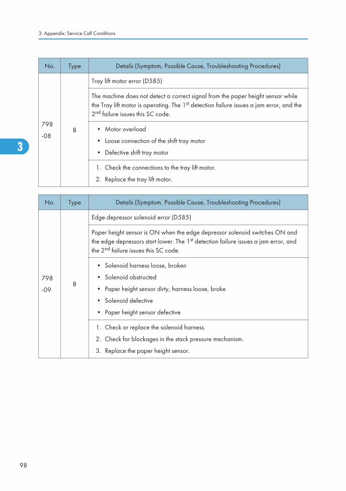
No. Type Details (Symptom, Possible Cause, Troubleshooting Procedures)
798
-08B
Tray lift motor error (D585)
The machine does not detect a correct signal from the paper height sensor whilethe Tray lift motor is operating. The 1st detection failure issues a jam error, and the2nd failure issues this SC code.
• Motor overload
• Loose connection of the shift tray motor
• Defective shift tray motor
1. Check the connections to the tray lift motor.
2. Replace the tray lift motor.
No. Type Details (Symptom, Possible Cause, Troubleshooting Procedures)
798
-09B
Edge depressor solenoid error (D585)
Paper height sensor is ON when the edge depressor solenoid switches ON andthe edge depressors start lower. The 1st detection failure issues a jam error, andthe 2nd failure issues this SC code.
• Solenoid harness loose, broken
• Solenoid obstructed
• Paper height sensor dirty, harness loose, broke
• Solenoid defective
• Paper height sensor defective
1. Check or replace the solenoid harness.
2. Check for blockages in the stack pressure mechanism.
3. Replace the paper height sensor.
3. Appendix: Service Call Conditions
98
3

SC8xx: Overall System
No. Type Details (Symptom, Possible Cause, Troubleshooting Procedures)
816 D
Energy saving I/O sub-system error
The energy saving I/O sub-system detects an error.
• Controller board defective
Replace the controller board.
No. Type Details (Symptom, Possible Cause, Troubleshooting Procedures)
817 D
Monitor Error
This is a file detection and electronic file signature check error when the bootloader attempts to read the self-diagnostic module, system kernel, or root systemfiles from the OS Flash ROM, or the items on the SD card in the controller slot arefalse or corrupted.
• OS Flash ROM data defective; change the controller firmware
• SD card data defective; use another SD card
No. Type Details (Symptom, Possible Cause, Troubleshooting Procedures)
818 D
Watchdog timer error
The watchdog timer detect the error even if system processing normally.
• System program defective
• Controller board defective
• Optional board defective
1. Turn the main switch off and on.
2. Replace controller firmware.
3. Replace controller board.
4. Replace the options.
Service Call Conditions
99
3

No. Type Details (Symptom, Possible Cause, Troubleshooting Procedures)
819 C
Fatal kernel error
Due to a control error, a RAM overflow occurred during system processing. Oneof the following messages was displayed on the operation panel.
• System program defective
• Controller board defective
• Optional board defective
Replace controller firmware
Note: For more details about this SC code error, execute SP5990 to print an SMC report so that youcan read the error code. The error code is not displayed on the operation panel.
No. Type Details (Symptom, Possible Cause, Troubleshooting Procedures)
820 DSelf-diagnostics error: CPU
[XXXX]: Detailed error code
[0001] to[06FF]
[0801] to[4005]
CPU error
During the self-diagnostic, the controller CPU detects an error. There are 47 typesof error code (0001 to 4005) depending on the cause of the error. The CPUdetects an error and displays the specific error code with the program addresswhere the error occurs.
• System firmware problem
• Defective controller
1. Turn the main switch off and on.
2. Reinstall the controller system firmware.
3. Replace the controller.
When the problem cannot be fixed with the above procedure, the followinginformation displayed on the screen needs to be fed back to a technical supportcenter.
• SC code
• Detailed error code
• Program address
3. Appendix: Service Call Conditions
100
3
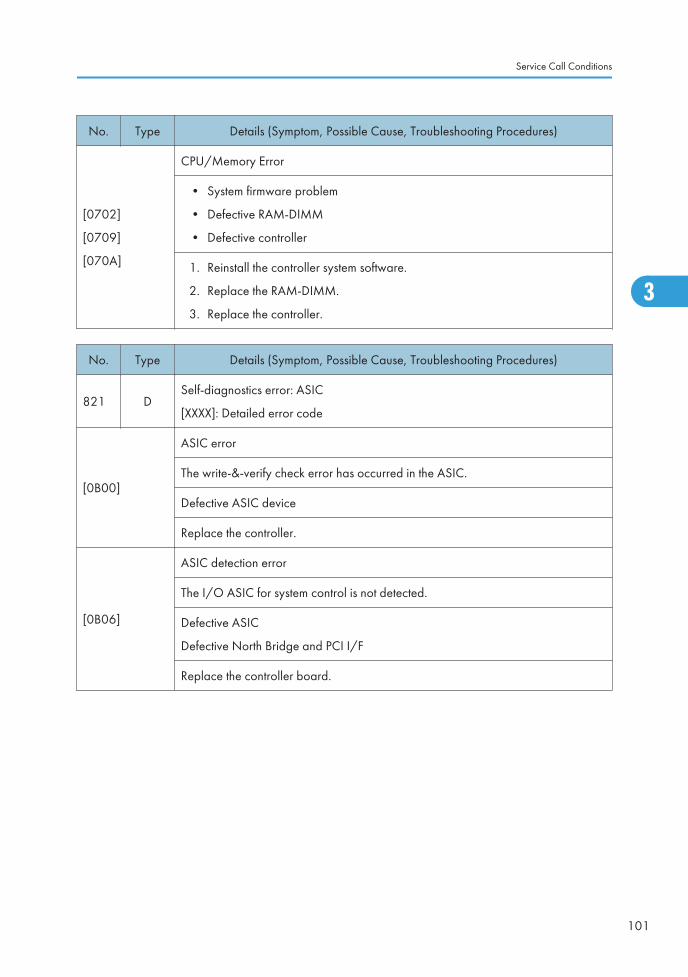
No. Type Details (Symptom, Possible Cause, Troubleshooting Procedures)
[0702]
[0709]
[070A]
CPU/Memory Error
• System firmware problem
• Defective RAM-DIMM
• Defective controller
1. Reinstall the controller system software.
2. Replace the RAM-DIMM.
3. Replace the controller.
No. Type Details (Symptom, Possible Cause, Troubleshooting Procedures)
821 DSelf-diagnostics error: ASIC
[XXXX]: Detailed error code
[0B00]
ASIC error
The write-&-verify check error has occurred in the ASIC.
Defective ASIC device
Replace the controller.
[0B06]
ASIC detection error
The I/O ASIC for system control is not detected.
Defective ASIC
Defective North Bridge and PCI I/F
Replace the controller board.
Service Call Conditions
101
3

No. Type Details (Symptom, Possible Cause, Troubleshooting Procedures)
[0D05]
Self-diagnosis error: ASIC
The CPU checks if the ASIC timer works correctly compared with the CPU timer. Ifthe ASIC timer does not function in the specified range, this SC code is displayed.
System firmware problem
Defective RAM-DIMM
Defective controller
1. Reinstall the controller system firmware.
2. Replace the RAM-DIMM.
3. Replace the controller board.
[50A1]
Video bridge device (ASIC) error 1
The CPU does not detect the video bridge device.
Defective I/F between the video bridge device and controller
Replace the controller.
[50A2]
Video bridge device (ASIC) register error 1
The CPU detects the video bridge device, but detects error data from the videobridge device.
Defective I/F between the video bridge device and controller
Replace the controller.
No. Type Details (Symptom, Possible Cause, Troubleshooting Procedures)
822 BSelf-diagnostic error: HDD (Hard Disk Drive)
[XXXX]: Detailed error code
[3003] Timeout error
[3004] Command error
- -When the main switch is turned on or starting the self-diagnostic, the HDD staysbusy for the specified time or more.
3. Appendix: Service Call Conditions
102
3

No. Type Details (Symptom, Possible Cause, Troubleshooting Procedures)
- -
• Loose connection
• Defective HDD
• Defective controller
- -
1. Check that the HDD is correctly connected to the controller.
2. Replace the HDD.
3. Replace the controller.
No. Type Details (Symptom, Possible Cause, Troubleshooting Procedures)
823 BSelf-diagnostic error: NIB
[XXXX]: Detailed error code
[6101]
MAC address check sum error
The result of the MAC address check sum does not match the check sum stored inROM.
[6104]PHY IC error
The PHY IC on the controller cannot be correctly recognized.
[6105]PHY IC loop-back error
An error occurred during the loop-back test for the PHY IC on the controller.
- Replace the controller.
No. Type Details (Symptom, Possible Cause, Troubleshooting Procedures)
824 C
Self-diagnosis error: Standard NVRAM
The controller cannot recognize the standard NVRAM installed or detects that theNVRAM is defective.
[1401]
• Loose connection
• Defective standard NVRAM
• Defective controller
1. Check the standard NVRAM is firmly inserted into the socket.
2. Replace the NVRAM.
3. Replace the controller
Service Call Conditions
103
3
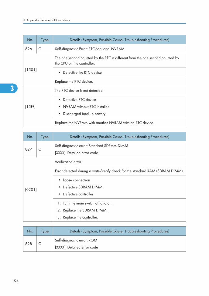
No. Type Details (Symptom, Possible Cause, Troubleshooting Procedures)
826 C Self-diagnostic Error: RTC/optional NVRAM
[1501]
The one second counted by the RTC is different from the one second counted bythe CPU on the controller.
• Defective the RTC device
Replace the RTC device.
[15FF]
The RTC device is not detected.
• Defective RTC device
• NVRAM without RTC installed
• Discharged backup battery
Replace the NVRAM with another NVRAM with an RTC device.
No. Type Details (Symptom, Possible Cause, Troubleshooting Procedures)
827 CSelf-diagnostic error: Standard SDRAM DIMM
[XXXX]: Detailed error code
[0201]
Verification error
Error detected during a write/verify check for the standard RAM (SDRAM DIMM).
• Loose connection
• Defective SDRAM DIMM
• Defective controller
1. Turn the main switch off and on.
2. Replace the SDRAM DIMM.
3. Replace the controller.
No. Type Details (Symptom, Possible Cause, Troubleshooting Procedures)
828 CSelf-diagnostic error: ROM
[XXXX]: Detailed error code
3. Appendix: Service Call Conditions
104
3

No. Type Details (Symptom, Possible Cause, Troubleshooting Procedures)
[0101]
Check sum error 1
The boot monitor and OS program stored in the ROM DIMM is checked. If thecheck sum of the program is incorrect, this SC code is displayed.
No. Type Details (Symptom, Possible Cause, Troubleshooting Procedures)
829 BSelf-diagnostic error: Optional RAM
[XXXX]: Detailed error code
[0301]
Verification error
Error detected during a write/verify check for the optional RAM (SDRAM DIMM).
• Loose connection
• Defective SDRAM DIMM
• Defective controller
1. Turn the main switch off and on.
2. Replace the SDRAM DIMM.
3. Replace the controller.
[0302]
Memory structure data error
The memory structure data error for the optional RAM (SDRAM DIMM) is detectedwhen the self-diagnostic is executed.
• Defective RAM DIMM
• Defective SPD ROM on RAM DIMM
• Defective 12C bus
Replace the RAM DIMM.
No. Type Details (Symptom, Possible Cause, Troubleshooting Procedures)
833 C Self-diagnostic error 8: Engine I/F ASIC
[0F30]
[0F31]
ASIC for system control could not be detected. After the PCI configuration, thedevice ID for the ASIC could not be checked.
Replace the IPU.
Service Call Conditions
105
3

No. Type Details (Symptom, Possible Cause, Troubleshooting Procedures)
[0F41]
ASIC for system control could not be detected. After the PCI configuration, thedevice ID for the ASIC could not be checked.
Replace the IPU.
[50B1]
Could not initialize or read the bus connection.
Check for loose connections at the mother board.
Replace the IPU.
[50B2]
Value of the SSCG register is incorrect.
Check for loose connections at the mother board.
Replace the IPU.
No. Type Details (Symptom, Possible Cause, Troubleshooting Procedures)
835 B Self-diagnostic error: Centronic device
[1102]
Loopback connector is connected but check results in an error.
• IEEE1284 connector error
• Centronic loopback connector defective
Replace the controller board.
[110C]
Loopback connector is connected but check results in an error.
• ASIC device error
• IEEE1284 connector error
• Centronic loopback connector defective
Replace the controller board.
[1120]
Centronic loopback connector is not connected for detailed self-diagnostic test.
• Centronic loopback connector not connected correctly
• Centronic loopback connector defective
• ASIC device defective
Replace the controller board.
3. Appendix: Service Call Conditions
106
3

No. Type Details (Symptom, Possible Cause, Troubleshooting Procedures)
838 C Self-diagnostic Error: Clock Generator
[2701]
A verify error occurred when setting data was read from the clock generator viathe I2C bus.
• Defective clock generator
• Defective I2C bus
• Defective I2C port on the CPU
Replace the controller board.
No. Type Details (Symptom, Possible Cause, Troubleshooting Procedures)
839 C
USB flash error
This is a self-diagnostic error. The device ID of the on-board USB flash ROM wasnot recognized.
• Defective controller board.
Replace the controller board
No. Type Details (Symptom, Possible Cause, Troubleshooting Procedures)
840 B
EEPROM error 1: EEPROM access
During the I/O processing, reading error is occurred. The 3rd reading failureissues this SC code.
• During the I/O processing, writing error is occurred.
• Defective EEPROM
Replace the EEPROM.
No. Type Details (Symptom, Possible Cause, Troubleshooting Procedures)
841 B
EEPROM error 2: EEPROM read/write error
Mirrored data of the EEPROM is different from the original data in EEPROM.
Data in the EEPROM is overwritten for some reasons.
Turn the main switch off and on.
Service Call Conditions
107
3

No. Type Details (Symptom, Possible Cause, Troubleshooting Procedures)
842 B
Flash ROM verification error
Verification error of the flash ROM on the controller board occurs.
• This SC is logged at 1st error detection.
• SC819 is issued at 2nd error detection.
• Defective flash ROM (controller board)
Replace the flash ROM.
No. Type Details (Symptom, Possible Cause, Troubleshooting Procedures)
851 B
IEEE 1394 I/F Abnormal
IEEE1394 interface error.
• IEEE1394 interface board defective
• Controller board defective
1. Turn the main switch off and on.
2. Replace the IEEE1394 interface board.
3. Replace the controller.
No. Type Details (Symptom, Possible Cause, Troubleshooting Procedures)
853 B
Wireless LAN board error 1
At startup the wireless LAN board could be accessed, but the wireless LAN board(IEEE 802.11b or Bluetooth) could not access the controller board.
• Wireless LAN board not installed when the machine was turned on
Check the wireless LAN board is installed correctly.
3. Appendix: Service Call Conditions
108
3

No. Type Details (Symptom, Possible Cause, Troubleshooting Procedures)
854 B
Wireless LAN board error 2
The board that holds the wireless LAN board can be accessed, but the wirelessLAN board (802.11b or Bluetooth) itself cannot be accessed while the machine isoperating
• Wireless LAN board has been removed during machine operation.
Check the wireless LAN board is installed correctly.
No. Type Details (Symptom, Possible Cause, Troubleshooting Procedures)
855 B
Wireless LAN board error 3
An error was detected for the wireless LAN board (802.11b or Bluetooth).
• Wireless LAN board defective
• Wireless board connection not tight
1. Check the connection.
2. Replace the wireless LAN/Bluetooth card.
No. Type Details (Symptom, Possible Cause, Troubleshooting Procedures)
857 B
USB I/F Error
The USB driver is unstable and generated an error. The USB I/F cannot be used.The USB driver can generate three types of errors: RX, CRC, and STALL errors.Only the STALL error can generate this SC code.
• USB 2.0 disconnected
• Controller board defective
1. Check the connection.
2. Replace the controller board.
No. Type Details (Symptom, Possible Cause, Troubleshooting Procedures)
858 AData encryption conversion error
A serious error occurred during data encryption.
Service Call Conditions
109
3

No. Type Details (Symptom, Possible Cause, Troubleshooting Procedures)
[0] A
Key acquisition error:
The controller fails to get a new encryption key.
• Defective controller board
Replace the controller board.
[1] A
HDD key setting error:
The controller fails to copy a new encryption key to the HDD.
Defective SATA chip on the controller board
• Turn the machine power off/on
• If the error reoccurs, replace the controller board
[2] A
NVRAM data encryption error 1:
An error occurs while the NVRAM data is encrypted.
Defective NVRAM on the controller board
• Replace the NVRAM
[30] A
NVRAM data encryption error 2:
An error occurs before the NVRAM data is encrypted.
Defective controller board
• Turn the machine power off/on
• If the error reoccurs, replace the controller board
[31] A
Other error:
A serious error occurs while the data is encrypted.
See SC991
No. Type Details (Symptom, Possible Cause, Troubleshooting Procedures)
859 BHDD data encryption error
Encryption of data on the hard disk failed.
3. Appendix: Service Call Conditions
110
3

No. Type Details (Symptom, Possible Cause, Troubleshooting Procedures)
[8] B
HDD check error:
The HDD is not correctly installed.
• No HDD installed
• Unformatted HDD
• The encryption key on the controller is different from the one on the HDD
1. Install the HDD correctly.
2. Initialize the HDD.
[9] B
Power loss during encryption
• Power failure during the data encryption
Format the HDD.
[10]
Data read/write error
• The DMAC error is detected twice or more.
See SC863 below.
No. Type Details (Symptom, Possible Cause, Troubleshooting Procedures)
860 B
HDD error 1
The hard disk connection is not detected because it is defective or has not beenformatted
• Cable between HDC and HDD loose or defective
• HDD power connector loose or defective
• HDD not formatted
• HDD defective
1. Check the cable between HDC and HDD.
2. Reformat the HDD.
3. Replace the HDD.
4. Replace the controller board.
Service Call Conditions
111
3

No. Type Details (Symptom, Possible Cause, Troubleshooting Procedures)
861 B
HDD error 2
The HDD did not enter the ready status within 30 sec. after power on.
• Cable between HDC and HDD loose or defective
• Cable between HDC and HDD loose or defective
• HDD power connector loose or defective
• HDD defective
1. Check the cable between HDC and HDD.
2. Reformat the HDD.
3. Replace the HDD.
4. Replace the controller board.
No. Type Details (Symptom, Possible Cause, Troubleshooting Procedures)
862 D
Bad sector number error
The number of bad sectors in the HDD (image data area) goes over 101.
• Defective HDD
1. Format the HDD with SP5-832-002.
2. Replace the HDD.
No. Type Details (Symptom, Possible Cause, Troubleshooting Procedures)
863 D
HDD error 3
Startup without HD data lead. Data stored on the hard disk is not read correctly,due to a bad sector on the HDD
• HDD defective
• Controller board defective
1. Format the HDD with SP5-832-002.
2. Replace the HDD.
3. Replace the controller board.
3. Appendix: Service Call Conditions
112
3

No. Type Details (Symptom, Possible Cause, Troubleshooting Procedures)
863 D
HDD error 4
HD data CRC error. During operation of the HD, the HD responded with a CRCerror.
• HDD defective
• Controller board defective
1. Format the HDD with SP5-832-002.
2. Replace the HDD.
3. Replace the controller board.
No. Type Details (Symptom, Possible Cause, Troubleshooting Procedures)
864 D
HDD error 4
While reading data from the HDD or storing data in the HDD, data transmissionfails.
• Defective HDD
1. Format the HDD with SP5-832-002.
1. Replace the HDD.
No. Type Details (Symptom, Possible Cause, Troubleshooting Procedures)
865 D
HDD error 5
HDD responded to an error during operation for a condition other than those forSC863 or 864.
• Defective HDD
1. Format the HDD with SP5-832-002.
1. Replace the HDD.
Service Call Conditions
113
3

No. Type Details (Symptom, Possible Cause, Troubleshooting Procedures)
866 B
SD card error 1: Recognition error
The SD card in the slot contains illegal program data.
• SD-card data is corrupted.
Use only SD cards that contain the correct data.
No. Type Details (Symptom, Possible Cause, Troubleshooting Procedures)
867 D
SD card error 2: SD card removed
The SD card in the boot slot when the machine was turned on was removed whilethe machine power was on.
• The SD card is ejected from the slot.
1. Install the SD card.
2. Turn the main switch off and on.
No. Type Details (Symptom, Possible Cause, Troubleshooting Procedures)
868 D
SD card error 3: SD card access
An error occurred while an SD card was used.
• SD card not inserted correctly
• SD card defective
• Controller board defective
Note: If you want to try to reformat the SD card, use SD Formatter Ver 1.1.
1. Check the SD card is inserted correctly.
2. Replace the SD card.
3. Replace the controller board.
3. Appendix: Service Call Conditions
114
3

No. Type Details (Symptom, Possible Cause, Troubleshooting Procedures)
870 B
Address Book Data Error
Address book data stored on the hard disk was detected as abnormal when it wasaccessed from either the operation panel or the network.
• Defective software program
• Defective HDD
• Incorrect path to the server
1. Initialize the address book data (SP5-846-050).
2. Initialize the user information (SP5-832-006).
3. Replace the HDD.
No. Type Details (Symptom, Possible Cause, Troubleshooting Procedures)
872 B
HDD mail RX data abnormal
An error was detected at power on. The data received during mail receive couldbe neither read nor written.
• Defective HDD
• Power failure during an access to the HDD
1. Turn the main switch off and on.
2. Initialize the HDD partition (SP5-832-007).
3. Replace the HDD.
No. Type Details (Symptom, Possible Cause, Troubleshooting Procedures)
873 B
HDD mail TX data error
An error was detected on the HDD immediately after the machine was turned on,or power was turned off while the machine used the HDD.
• Defective HDD
• Power failure during an access to the HDD
1. Do SP5832-8 (Format HDD – Mail TX Data) to initialize the HDD.
2. Replace the HDD.
Service Call Conditions
115
3

No. Type Details (Symptom, Possible Cause, Troubleshooting Procedures)
874 D
Delete All error 1: HDD
A data error was detected for the HDD/NVRAM after the Delete All option wasused.
Note: The source of this error is the Data Overwrite Security Unit D362 runningfrom an SD card.
• Data Overwrite Security Unit (SD card) not installed
• Defective HDD
1. Turn the main switch off/on, and try the operation again.
2. Install the Data Overwrite Security Unit.
3. Replace the HDD.
No. Type Details (Symptom, Possible Cause, Troubleshooting Procedures)
875 D
Delete All error 2: Data area
An error occurred while the machine deleted data from the HDD.
Note: The source of this error is the Data Overwrite Security Unit running from anSD card.
• The logical format for the HDD fails.
Turn the main switch off/on, and try the operation again.
No. Type Details (Symptom, Possible Cause, Troubleshooting Procedures)
876CTL
D
Log Data Error
An error was detected in the handling of the log data at power on or duringmachine operation. This can be caused by switching the machine off while it isoperating.
-001
Log Data Error 1
• Damaged log data file in the HDD
Initialize the HDD with SP5832-004.
3. Appendix: Service Call Conditions
116
3

No. Type Details (Symptom, Possible Cause, Troubleshooting Procedures)
-002
Log Data Error 2
• An encryption module not installed
1. Disable the log encryption setting with SP9730-004 ("0" is off.)
2. Install the DESS module.
-003
Log Data Error 3
• Invalid log encryption key due to defective NVRAM data
1. Initialize the HDD with SP5832-004.
2. Disable the log encryption setting with SP9730-004 ("0" is off.)
-004
Log Data Error 4
• Unusual log encryption function due to defective NVRAM data
Initialize the HDD with SP5832-004.
-005
Log Data Error 5
• Installed NVRAM or HDD which is used in another machine
1. Reinstall the previous NVRAM or HDD.
2. Initialize the HDD with SP5832-004.
-099
Log Data Error 99
• Other than the above causes
Ask your supervisor.
No. Type Details (Symptom, Possible Cause, Troubleshooting Procedures)
877 B
Data Overwrite Security SD card error
The 'all delete' function did not execute but the Data Overwrite Security Unit isinstalled and activated.
• Defective SD card
• SD card not installed
1. Replace the NVRAM and then install the new SD card.
2. Check and reinstall the SD card.
Service Call Conditions
117
3

No. Type Details (Symptom, Possible Cause, Troubleshooting Procedures)
878 D
TPM electronic recognition error
The main machine firmware failed to recognize TPM because USB flash is notoperating or a system module was updated incorrectly.
• Incorrect updating for the system firmware
• Defective flash ROM on the controller board
Replace the controller board
No. Type Details (Symptom, Possible Cause, Troubleshooting Procedures)
880 D
File format converter error
A request for access to the File Format Converter (MLB) was not answered withinthe specified time.
• File format converter disconnected
• Defective file format converter
1. Check the file format converter is connected correctly.
2. Replace the file format converter.
No. Type Details (Symptom, Possible Cause, Troubleshooting Procedures)
881 D
Authentication area error
Authentication application error is detected.
• Error data in an authentication application reaches the management limit.
Turn the main switch off and on.
3. Appendix: Service Call Conditions
118
3

No. Type Details (Symptom, Possible Cause, Troubleshooting Procedures)
899 D
Software performance error
If the processing program shows abnormal performance and the program isabend, this SC is issued.
• Controller board defective
• Software defective
1. Replace the controller board.
2. Turn the main switch off and on.
3. Update the firmware on the controller.
SC9xx: Miscellaneous
No. Type Details (Symptom, Possible Cause, Troubleshooting Procedures)
900 D
Electrical total counter error
The total count contains something that is not a number.
• NVRAM incorrect type
• NVRAM defective
• NVRAM data scrambled
• Unexpected error from external source
1. Check the connection between the NVRAM and controller.
2. Replace the NVRAM.
3. Replace the controller board.
No. Type Details (Symptom, Possible Cause, Troubleshooting Procedures)
901 D
Mechanical total counter error
The counter was moved during standby or while it is operating, possibly damagingthe connector.
• Counter defective
Check the connection of the mechanical counter
Service Call Conditions
119
3

No. Type Details (Symptom, Possible Cause, Troubleshooting Procedures)
920 B
Printer Error 1
An internal application error was detected and operation cannot continue.
• Software defective
• Unexpected hardware resource (e.g., memory shortage)
1. Software defective; switch off/on, or change the controller firmware if theproblem is not solved
2. Insufficient memory
No. Type Details (Symptom, Possible Cause, Troubleshooting Procedures)
921 B
Printer error 2
When the application started, the necessary font was not on the SD card.
• A necessary font is not found in the SD card.
• The SD card data is corrupted.
Check that the SD card has the correct data.
No. Type Details (Symptom, Possible Cause, Troubleshooting Procedures)
925 B
Network File Error
The file that manages NetFile is corrupted and operation cannot continue.
• Software defective
• Files on the HDD corrupted
1. Do SP5-832 to format the HDD.
2. Replace the HDD.
3. Appendix: Service Call Conditions
120
3

No. Type Details (Symptom, Possible Cause, Troubleshooting Procedures)
990 B
Software performance error
The software attempted to perform an unexpected operation due to: 1) softwarebug, 2) incorrect internal parameter, 3) insufficient working memory.
• Defective software
• Defective controller
• Software error
• Turn the machine power off/on
• Reinstall the controller and/or main firmware
Note: When this SC occurs, the file name, address, and data will be stored inNVRAM. This information can be checked by using SP7-403. Note the abovedata and the situation in which this SC occurs. Then report the data and conditionsto your technical control center.
No. Type Details (Symptom, Possible Cause, Troubleshooting Procedures)
991 C
Software continuity error
The software attempted to perform an unexpected operation. However, unlikeSC990, the object of the error is continuity of the software.
• Software program error
• Internal parameter incorrect, insufficient working memory.
This SC is not displayed on the LCD (logging only).
No. Type Details (Symptom, Possible Cause, Troubleshooting Procedures)
992 D
Unexpected Software Error
Software encountered an unexpected operation not defined under any SC code.
• Software defective
• An error undetectable by any other SC code occurred
Print the "Logging Data" with SP5990-004 and then check the SP7990.
If 498-Engine is found in the SP7990;
1. Check the harness connection of the temperature/humidity sensor.
2. Replace the temperature/humidity sensor.
Service Call Conditions
121
3

No. Type Details (Symptom, Possible Cause, Troubleshooting Procedures)
994 C
OCS record limitation error
An error occurred because the number of records exceeded the limit for imagesmanaged in the service layer of the firmware. This can occur if there if there are toomany application screens open on the operation panel.
• No action required because this SC does not interfere with operation of themachine.
No. Type Details (Symptom, Possible Cause, Troubleshooting Procedures)
995 D Controller Board Mismatch
-001
• Defective BCU
• NVRAM Replacement error
1. Install the previous NVRAM.
2. Input the serial number with SP5811-004, and turn the main power switchoff/on.
-002
• Defective NVRAM
• Defective controller
1. Update the controller firmware.
2. Install a new NVRAM, and turn off and on the main power switch afterSC995-002 has occurred.
-003
• Incorrect type controller installed
• Defective controller
Replace the controller with the correct type.
-004• Incorrect model controller installed.
Replace the controller with the correct model.
3. Appendix: Service Call Conditions
122
3

No. Type Details (Symptom, Possible Cause, Troubleshooting Procedures)
997CTL
B
Application function selection error
The application selected by the operation panel key does not start or endsabnormally.
• Software (including the software configuration) defective
• An option required by the application (RAM, DIMM, board) is not installed
• Nesting of the fax group addresses is too complicated
1. Check the devices necessary for the application program. If necessarydevices have not been installed, install them.
2. Check that application programs are correctly configured.
3. For a fax operation problem, simplify the nesting of the fax group addresses.
4. Take necessary countermeasures specific to the application program. If thelogs can be displayed on the operation panel, see the logs.
No. Type Details (Symptom, Possible Cause, Troubleshooting Procedures)
998CTL
D
Application start error
No applications start within 60 seconds after the power is turned on.
• Loose connection of RAM-DIMM, ROM-DIMM
• Defective controller
• Software problem
1. Check the setting of SP5875-001. If the setting is set to "1 (OFF)", change itto "0 (OFF)".
2. Check if the RAM-DIMM and ROM-DIMM are correctly connected.
3. Reinstall the controller system firmware.
4. Replace the controller.
Note 1
If a problem always occurs under specific conditions (for example. printer driver setting, image file), theproblem may be caused by a software error. In this case, the following data and information need to besent back to your product specialist. Please understand that it may take some time to get a reply on howto solve the problem, because in some cases the design staff in Japan must analyze the data.
• Symptom / Possible Causes / Action taken
• Summary sheet (SP mode "Printer SP", SP1-004 [Print Summary])
Service Call Conditions
123
3

• SMC - All (SP5-990-001)
• SMC - Logging (SP5-990-004)
• Printer driver settings used when the problem occurs
• All data displayed on the screen (SC code, error code, and program address where the problem islogged.)
• Image file which causes the problem, if possible
3. Appendix: Service Call Conditions
124
3
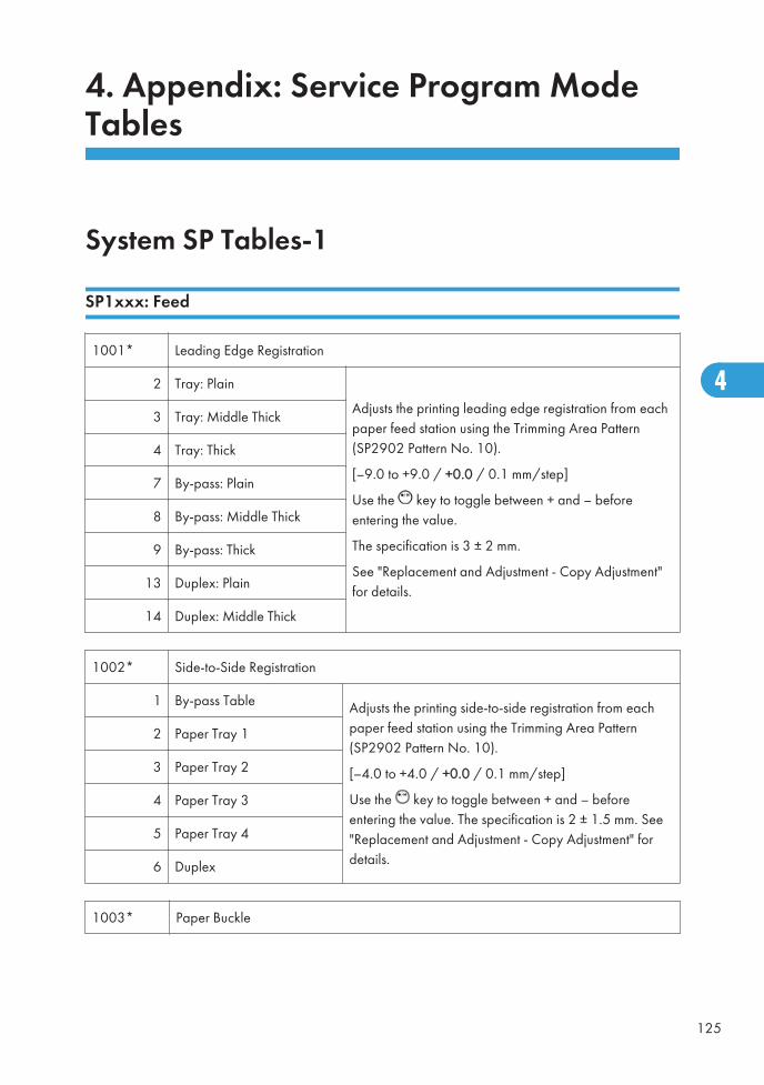
4. Appendix: Service Program ModeTables
System SP Tables-1
SP1xxx: Feed
1001* Leading Edge Registration
2 Tray: Plain
Adjusts the printing leading edge registration from eachpaper feed station using the Trimming Area Pattern(SP2902 Pattern No. 10).
[–9.0 to +9.0 / +0.0 / 0.1 mm/step]
Use the key to toggle between + and – beforeentering the value.
The specification is 3 ± 2 mm.
See "Replacement and Adjustment - Copy Adjustment"for details.
3 Tray: Middle Thick
4 Tray: Thick
7 By-pass: Plain
8 By-pass: Middle Thick
9 By-pass: Thick
13 Duplex: Plain
14 Duplex: Middle Thick
1002* Side-to-Side Registration
1 By-pass Table Adjusts the printing side-to-side registration from eachpaper feed station using the Trimming Area Pattern(SP2902 Pattern No. 10).
[–4.0 to +4.0 / +0.0 / 0.1 mm/step]
Use the key to toggle between + and – beforeentering the value. The specification is 2 ± 1.5 mm. See"Replacement and Adjustment - Copy Adjustment" fordetails.
2 Paper Tray 1
3 Paper Tray 2
4 Paper Tray 3
5 Paper Tray 4
6 Duplex
1003* Paper Buckle
125
4

2 Paper Tray 1: Plain
Adjusts the paper feed clutch timing at registration. Thepaper feed clutch timing determines the amount ofpaper buckle at registration. (A larger setting leads tomore buckling.)
[–9 to 5 / 0 / 1 mm/step]
3 Tray 1: Middle Thick
4 Paper Tray 1: Thick
7Paper Tray 2/3/4/LCT:Plain
8Paper Tray 2/3/4/LCT:Middle Thick
9Paper Tray 2/3/4/LCT:Thick
12 By-pass: Plain
13 By-pass: Middle Thick
14 By-pass: Thick
18 Duplex: Plain
19 Duplex: Middle Thick
1007*By-pass Paper Size
Controls paper size detection for the by-pass feed table.
1
LG Detection
[0 to 1 / 0 / -]
0: LTSEF, 1: LG
1101*
Flicker Control
Switches flicker control on/off.
[0 = Off / 1 = On]
1103* Fusing Idling
4. Appendix: Service Program Mode Tables
126
4

1 Fusing Idling
Switches fusing idling on/off.
[0 = Off / 1 = On / 2 = Off plus machinetemperature check]
Switch on if fusing on the 1st and 2nd copies isincomplete (this may occur if the room is cold.)
2Reload Permit Setting:ReloadTemp.:Center
Adjusts the reload temperature at the center andboth ends of the hot roller when the temperatureinside the machine is 17°C or higher.
[100 to 150 / 130 / 1°C/step]3Reload Permit Setting:ReloadTemp.:Ends
4Reload Permit Setting:ReloadTemp.:Cold:Center
Adjusts the reload temperature at the center andboth ends of the hot roller when the temperatureinside the machine is 16°C or lower.
[100 to 150 / 130 / 1°C/step]5Reload Permit Setting:ReloadTemp.:Cold:Ends
1105* Fusing Temperature Adjustment
1 Roller Center:Plain1 Adjusts the fusing temperature at the center andboth ends of the hot roller for plain paper 1.
D120/D139:[120 to 200 / 155 / 1°C/step]
D121/D122/D140/D141:[120 to 200 /165 / 1°C/step]
2 Roller Ends:Plain1
3 Roller Center:Plain2 Adjusts the fusing temperature at the center andboth ends of the hot roller for plain paper 2.
D120/D139:[120 to 200 / 160 / 1°C/step]
D121/D122/D140/D141:[120 to 200 /170 / 1°C/step]
4 Roller Ends:Plain2
5 Roller Center:M-Thick Adjusts the fusing temperature at the center andboth ends of the hot roller for middle thickpaper.
D120/D139:[120 to 200 / 165 / 1°C/step]
D121/D122/D140/D141:[120 to 200 /175 / 1°C/step]
6 Roller Ends:M-Thick
System SP Tables-1
127
4

7 Thick Paper - Roller Center Adjusts the additional temperature for the centerand both ends of the hot roller for thick paper.
D120/D139:[ 0 to 40 / 25 / 1°C/step]
D121/D122/D140/D141:[0 to 40 / 20 /1°C/step]
8 Thick Paper - Roller Ends
9 Center Minus:Thin Adjusts the subtract temperature for the centerand both ends of the hot roller for thick paper.
[0 to 20 / 5 / 1°C/step]10 Ends Minus:Thin
11 Energy Saver
Adjusts the fusing temperature at the center andboth ends of the hot roller for energy savermode.
D120/D139:[ 0 to 200 / 135 / 1°C/step]
D121/D122/D140/D141:[0 to 200 / 145 /1°C/step]
12 Wait Temp: Center Minus Adjusts the subtract temperature for the centerand both ends of the hot roller in stand-bymode.
[0 to 30 / 5 / 1 °C]13 Wait Temp: Ends Minus
14 After Warming-up Time
In this machine, fusing temperature is kept 10°Chigher than the normal temperature for a shortwhile after the machine warms up. This SPselects the length of time that this temperature isused.
[0 to 180 / 12 / 1s/step]
15 After Warming-up - No. of Page
In this machine, fusing temperature is kept 10°Chigher than the normal temperature for anumber of pages after the machine has warmedup. This SP selects the number of pages made atthis temperature.
[0 to 10 / 3 / 1 page/step]
16 Low:Center Add:Plain Adjusts the additional temperature for the centerand both ends of the hot roller for printing onthin paper/plain paper 1/plain paper 2/middle thick paper when the temperature insidethe machine is 16 °C or lower.
[0 to 30 / 5 / 1 °C]
17 Low:Ends Add:Plain
4. Appendix: Service Program Mode Tables
128
4

18 Low:Center Add:Thick Adjusts the additional temperature for the centerand both ends of the hot roller for printing onthick paper when the temperature inside themachine is 16 °C or lower.
[0 to 30 / 5 / 1 °C]
19 Low:Ends Add:Thick
20 Registration Waiting:Plain1 Turns the registration waiting mode on or off foreach paper type.
[0 to 1 / 0 / 1]
0=Off, 1=On
The paper waits at the registration roller until thefusing temperature reaches the prescribedtemperature (adjustable with SP1105-024 to-31).
21 Registration Waiting:Plain2
22 Registration Waiting:M-Thick
23 Registration Waiting:Thick
Turns the registration waiting mode on or off foreach paper type.
[0 to 1 / 1 / 1]
0=Off, 1=On
The paper waits at the registration roller until thefusing temperature reaches the prescribedtemperature (adjustable with SP1105-024 to-31).
24 Waiting:Center Minus:Plain1
Adjusts the offset value for each re-loadtemperature to exit the registration waitingmode.
[0 to 60 / 10 / 1 deg]
25 Waiting:Ends Minus:Plain1
26 Waiting:Center Minus:Plain2
27 Waiting:Ends Minus:Plain2
28 Waiting:Center Minus:M-Thick
29 Waiting:Ends Minus:M-Thick
30 Waiting:Center Minus:Thick
31 Waiting:Ends Minus:Thick
System SP Tables-1
129
4

32 Down Temp:No. of Page
When the fusing temperature at the center of thehot roller is lowered due to consecutive printing,the lowered temperature is kept until the numberof sheets set here is printed.
[0 to 20 / 5 / 1 sheet]
33 Copy Down Temp
When the fusing temperature at both ends of thehot roller is lowered due to consecutive printing,the lowered temperature is kept until the numberof sheets set here are printed.
[0 to 20 / 5 / 1 sheet]
34 Copy Down Temp:Center Adjusts the subtract temperature for the centerand both ends of the hot roller when themachine lowers the temperature due toconsecutive printing.
[0 to 30 / 1 / 1 deg]
35 Copy Down Temp:Ends
36 Copy Down Temp:Add:Center Adjusts the additional temperature until aspecified period of time passes or a specifiednumber of sheets are printed after reload.
[0 to 30 / 5 / 1 deg]37 Copy Down Temp:Add:Ends
38 Feed Permit Setting:Thick
Adjusts the temperature at which feeding thickpaper is permitted. Thick paper can be fedwhen the specified fusing temperature minus theactual temperature is the same as or smallerthan this setting.
[0 to 60 / 20 / 1 deg]
1106 Fusing Temperature Display
1 Roller Center Displays the fusing temperature for the center or bothends of the hot roller.2 Roller Ends
3 In the Machine at Power On
Displays the temperature in the machine at power on.
This temperature is monitored by the thermistor on theBCU board.
1108* Fusing Soft Start Setting
4. Appendix: Service Program Mode Tables
130
4

1 Warming-up
Adjusts the fusing temperature control cycle when themachine is warming up.
[100 to 2000 / 1000 / 100 msec]
2 Print
Adjusts the fusing temperature control cycle when themachine is printing.
[100 to 2000 / 1000 / 100 msec]
3 WaitAdjusts the fusing temperature control cycle [100 to2000 / 1000 (North America, Taiwan), 2000 (Othercountries) / 100 msec]
1112* Image Proc. Temp. Correction
1 Temp.:Normal:Level1
Specifies the correction temperature for the level1 of the job image control.
[–25 to 10 / 0 / 1 deg]
2 Temp.:Normal:Level2
Specifies the correction temperature for the level2 of the job image control.
[–25 to 10 / –5 / 1 deg]
1124*CPM Down Setting
Specifies the settings for the CPM down mode.
6 High:1st CPM
Specifies the 1st CPM down ratio against thenormal CPM in the high temperature condition.
[10 to 100 / 60 / 5 %/step]
7 High:2nd CPM
Specifies the 2nd CPM down ratio against thenormal CPM in the high temperature condition.
[10 to 100 / 50 / 5 %/step]
8 High:3rd CPM
Specifies the 3rd CPM down ratio against thenormal CPM in the high temperature condition.
[10 to 100 / 25 / 5 %/step]
9 High:1st CPM Down Temp.:A3
Specifies the heating roller temperature for 1stCPM down of A3 paper size.
[100 to 250 / 215 / 1 deg/step]
System SP Tables-1
131
4

10 High:2nd CPM Down Temp.:A3
Specifies the heating roller temperature for 2ndCPM down of A3 paper size.
[100 to 250 / 220 / 1 deg/step]
11 High:3rd CPM Down Temp.:A3
Specifies the heating roller temperature for 3rdCPM down of A3 paper size.
[100 to 250 / 225 / 1 deg/step]
12 High:1st CPM Down Temp.:A4
Specifies the heating roller temperature for 1stCPM down of A4 paper size.
[100 to 250 / 215 / 1 deg/step]
13 High:2nd CPM Down Temp.:A4
Specifies the heating roller temperature for 2ndCPM down of A4 paper size.
[100 to 250 / 220 / 1 deg/step]
14 High:3rd CPM Down Temp.:A4
Specifies the heating roller temperature for 3rdCPM down of A4 paper size.
[100 to 250 / 225 / 1 deg/step]
15High:1st CPM DownTemp.:B5:Press
Specifies the pressure roller temperature for 1stCPM down of B5 paper size.
[100 to 250 / 200 / 1 deg/step]
16High:2nd CPM DownTemp.:B5:Press
Specifies the pressure roller temperature for 2ndCPM down of B5 paper size.
[100 to 250 / 205 / 1 deg/step]
17High:3rd CPM DownTemp.:B5:Press
Specifies the pressure roller temperature for 3rdCPM down of B5 paper size.
[100 to 250 / 210 / 1 deg/step]
18High:1st CPM DownTemp.:A5:Press
Specifies the pressure roller temperature for 1stCPM down of A5 paper size.
[100 to 250 / 200 / 1 deg/step]
19High:2nd CPM DownTemp.:A5:Press
Specifies the pressure roller temperature for 2ndCPM down of A5 paper size.
[100 to 250 / 205 / 1 deg/step]
4. Appendix: Service Program Mode Tables
132
4

20High:3rd CPM DownTemp.:A5:Press
Specifies the pressure roller temperature for 3rdCPM down of A5 paper size.
[100 to 250 / 210 / 1 deg/step]
21High:1st CPM DownTemp.:A6:Press
Specifies the pressure roller temperature for 1stCPM down of A6 paper size.
[100 to 250 / 200 / 1 deg/step]
22High:2nd CPM DownTemp.:A6:Press
Specifies the pressure roller temperature for 2ndCPM down of A6 paper size.
[100 to 250 / 205 / 1 deg/step]
23High:3rd CPM DownTemp.:A6:Press
Specifies the pressure roller temperature for 3rdCPM down of A6 paper size.
[100 to 250 / 210 / 1 deg/step]
24 Judging IntervalSpecifies the interval for CPM down judgement.
[1 to 250 / 10 / 1 sec/step]
1152*Fusing Nip Band Check
Checks the fusing nip band.
1 ExecuteExecutes the fusing nip band check from the by-pass tray.
2* Pre-idling Time
Specifies the fusing rotation time beforeexecuting SP1152-001.
[0 to 999 / 20 / 1 sec/step]
3* Stop TimeSpecifies the time for paper staying at the nip.
[0 to 100 / 20 / 1 sec/step]
1159*
Fusing Jam Detection
Disables or enables the consecutive jam error for the fusing unit.
[0 to 1 / 0 / 1 Step]
When set to "1" (on) this SC code is issued after the 3rd consecutive jam in the fusingunit.
1801* MotorSpeedAdjust
System SP Tables-1
133
4

1 MainMotor:150 [–4 to 4 / 0 / 0.01 %/step]
2 MainMotor:122 [–4 to 4 / 0 / 0.01 %/step]
10 Duplex:Low [–4 to 4 / 0 / 0.01 %/step]
11 Duplex:High [–4 to 4 / 0 / 0.01 %/step]
24 Reverse:Low [–4 to 4 / 0 / 0.01 %/step]
29 Reverse:High [–4 to 4 / 0 / 0.01 %/step]
1903*
Feed Cl Re-energize
Adjusts the paper feed amount allowed by the clutch after correcting the skew atregistration. When paper jams occur after restarting paper feed after registration,increase the value to help the registration roller feed the paper.
1 By-pass Feed
[0 to 10 / 5 / 1 mm/step]2 Tray 1 Feed
3 Other Trays
1907* Paper Feed Timing Adj.
1 Feed Solenoid ON
[-10 to 10 / 0 / 1mm /step]5 Inverter Stop Position
15 Re-Feed Stop Position
20 Bank1: Feed Solenoid ON: Plain The feed solenoid turns on A mm beforethe pick-up roller feed out the trailingedge of the paper.
A=(Original length – 80) x B / 100
B=setting value
[35 to 85 / 60 / 5% /step]
21 Bank1: Feed Solenoid ON: Middle Thick
4. Appendix: Service Program Mode Tables
134
4

22 Bank1: Feed Solenoid ON: Thick 1
The feed solenoid turns on A mm beforethe pick-up roller feed out the trailingedge of the paper.
A=(Original length – 80) x B / 100
B=setting value
[35 to 85 / 35 / 5% /step]
23 Bank2: Feed Solenoid ON: Plain The feed solenoid turns on A mm beforethe pick-up roller feed out the trailingedge of the paper.
A=(Original length – 80) x B / 100
B=setting value
[35 to 85 / 60 / 5% /step]
24 Bank2: Feed Solenoid ON: Middle Thick
25 Bank2: Feed Solenoid ON: Thick 1
The feed solenoid turns on A mm beforethe pick-up roller feed out the trailingedge of the paper.
A=(Original length – 80) x B / 100
B=setting value
[35 to 85 / 35 / 5% /step]
26 Bank1: Feed Clutch OFF: Plain
The feed solenoid turns off A mm after thepick-up roller feed out the trailing edge ofthe paper.
A=4 + B
B=setting value
[-10 to 10 / 0 / 1mm /step]
27 Bank1: Feed Clutch OFF: Middle Thick
28 Bank1: Feed Clutch OFF: Thick 1
29 Bank2: Feed Clutch OFF: Plain
30 Bank2: Feed Clutch OFF: Middle Thick
31 Bank2: Feed Clutch OFF: Thick 1
32 Bank Feed Wait Position
Stop and hold the paper A mm after theleading edge of the paper activates thevertical transport sensor.
A=setting value
[-20 to 20 / 0 / 1mm /step]
1908* Paper Feed Timing Adj.
System SP Tables-1
135
4

15 Junction Gate SOL1: ON[-10 to 10 / 0 / 1mm /step]
17 Junction Gate SOL1: OFF
20 Bridge Junction Gate SOL ON: Plain The bridge junction gate solenoid turns onA mm after the leading edge of the paperactivates the paper exit sensor.
A=setting value
[0 to 20 / 0 / 1mm /step]
21Bridge Junction Gate SOL ON: MiddleThick
22 Bridge Junction Gate SOL ON: Thick 1
23 Bridge Junction Gate SOL OFF: Plain The bridge junction gate solenoid turns offA mm after the leading edge of the paperactivates the paper exit sensor.
A=setting value
[0 to 50 / 0 / 1mm /step]
24Bridge Junction Gate SOL OFF: MiddleThick
25 Bridge Junction Gate SOL OFF: Thick 1
1950*
Fan Cooling Time Set
Adjust the rotation time for the fan motor (Fan for PSU, fusing, heater, controller box)after a job end.
[10 to 600 / 10 / 1 sec]
1991*Max Fusing Lamp Duty DFU
These SP codes are debugging tools.
1 Roller Center
[40 to 100/100/10%]2 Roller Ends
3 After Warming-up – Center
4 After Warming-up - Ends
1996*
Heater Forced Off After Printing
Adjusts the period of time the fusing fan is off after printing. After the final sheet exits thefusing unit, the machine turns the fan off by setting the fusing temperature to reloadtemperature.
[0 to 120/1/1 sec]
4. Appendix: Service Program Mode Tables
136
4

System SP Tables-2
SP2xxx: Drum
2001* Charge Roller Bias
1
Setting (Copying)
Adjusts the voltage applied to the charge roller during printing.
This value will be changed automatically when the charge roller bias correction isperformed.
Note that if this value is changed, the charge roller voltage will be corrected based onthe new voltage.
[–2100 to –1500 / –1700 / 10 V/step]
2
Adjust ID Sensor Pattern
Adjusts the voltage applied to the charge roller when making the Vsdp ID sensorpattern (for charge roller bias correction).
The actual charge roller voltage is this value plus the value of SP2001 1.
[0 to 400 / 200 / 10 V/step]
3
Temporary Input
Inputs the charge roller voltage temporarily for test purposes.
Do not change the value.
[0 to –2500 / 0 / 10 V/step]
2005* Charge Bias Correction
1
Vsdp Min
Adjusts the lower threshold value for the charge roller correction.
When the value of Vsdp/Vsg is less than this value, the charge roller voltage increasesby 50V (e.g. from –500 to –550). The size of the increase depends on SP2005 3.
[0 to 100 / 90 / 1%/step]
System SP Tables-2
137
4

2
Vsdp Max
Adjusts the upper threshold value for the charge roller correction.
When the value of Vsdp/Vsg is greater than this value, the charge roller voltagedecreases by 50V (e.g. from –550 to –500). The size of the decrease depends onSP2005 3.
[0 to 100 / 95 / 1 %/step]
3
Charge Roller Bias Correction (Step)
Adjusts the size of the charge roller voltage correction.
[0 to 200 / 50 / 1 V/step]
2102*
Main Scan Mag. Adjustment
Adjusts the magnification in the main scan direction for copy mode and printer mode.Press "Clear/Stop" key to toggle plus or minus.
[–0.5 to 0.5 / 0 / 0.1 %]
2103 Erase Margin Adjust
1
Leading Edge
Adjusts the leading edge erase margin.
The specification is 3 ±2 mm. See "Replacement and Adjustment - Copy Adjustment" fordetails.
[0.0 to 4.0 / 3.0 / 0.1 mm/step]
2
Trailing Edge
Adjusts the trailing edge erase margin.
The specification is 0.5 mm or more. See "Replacement and Adjustment - CopyAdjustment" for details.
[0.0 to 4.0 / 3.0 / 0.1 mm/step]
3
Left Side
Adjusts the left edge erase margin.
The specification is 2 ±1.5 mm. See "Replacement and Adjustment - Copy Adjustment"for details.
[0.0 to 4.0 / 2.0 / 0.1 mm/step]
4. Appendix: Service Program Mode Tables
138
4

4
Right Side
Adjusts the right edge erase margin.
The specification is 2 +2.5/-1.5 mm. See "Replacement and Adjustment - CopyAdjustment" for details.
[0.0 to 4.0 / 2.0 / 0.1 mm/step]
5
Duplex Trail.: L Size: Plain
Adjusts the trailing edge erase margin on the reverse side of duplex copies for plainpaper longer than 297 mm.
The actual trailing edge erase margin on the reverse side is this value plus the value ofSP2101-2.
The specification is 0.5 mm or more. See "Replacement and Adjustment - CopyAdjustment" for details
[0.0 to 4.0 / 1.2 / 0.1 mm/step]
6
Duplex Trail.: M Size: Plain
Adjusts the trailing edge erase margin on the reverse side of duplex copies for plainpaper of length 216.1 to 297 mm.
The actual trailing edge erase margin on the reverse side is this value plus the value ofSP2101-2.
The specification is 0.5 mm or more. See "Replacement and Adjustment - CopyAdjustment" for details
[0.0 to 4.0 / 0.8 / 0.1 mm/step]
7
Duplex Trail.: S Size: Plain
Adjusts the trailing edge erase margin on the reverse side of duplex copies for plainpaper of length 216 mm or less.
The actual trailing edge erase margin on the reverse side is this value plus the value ofSP2101-2.
The specification is 0.5 mm or more. See "Replacement and Adjustment - CopyAdjustment" for details
[0.0 to 4.0 / 0.6 / 0.1 mm/step]
System SP Tables-2
139
4

8
Duplex Left: Plain
Adjusts the left side erase margin on the reverse side of duplex copies.
The actual left side erase margin on the reverse side is this value plus the value ofSP2101-3.
The specification is 2 ±1.5 mm. See "Replacement and Adjustment - Copy Adjustment"for details.
[0.0 to 1.5 / 0.3 / 0.1 mm/step]
9
Duplex Right: Plain
Adjusts the right side erase margin on the reverse side of duplex copies.
The actual right side erase margin on the reverse side is this value plus the value ofSP2101-4.
The specification is 2 +2.5/–1.5 mm. See "Replacement and Adjustment - CopyAdjustment" for details.
[0.0 to 1.5 / 0.3 / 0.1 mm/step]
10
Duplex Trail.: L Size: Thick
Adjusts the trailing edge erase margin on the reverse side of duplex copies for thickpaper longer than 297 mm.
The actual trailing edge erase margin on the reverse side is this value plus the value ofSP2101-2.
The specification is 0.5 mm or more. See "Replacement and Adjustment - CopyAdjustment" for details
[0.0 to 4.0 / 1 / 0.1 mm/step]
11
Duplex Trail.: M Size: Thick
Adjusts the trailing edge erase margin on the reverse side of duplex copies for thickpaper of length 216.1 to 297 mm.
The actual trailing edge erase margin on the reverse side is this value plus the value ofSP2101-2.
The specification is 0.5 mm or more. See "Replacement and Adjustment - CopyAdjustment" for details
[0.0 to 4.0 / 0.6 / 0.1 mm/step]
4. Appendix: Service Program Mode Tables
140
4
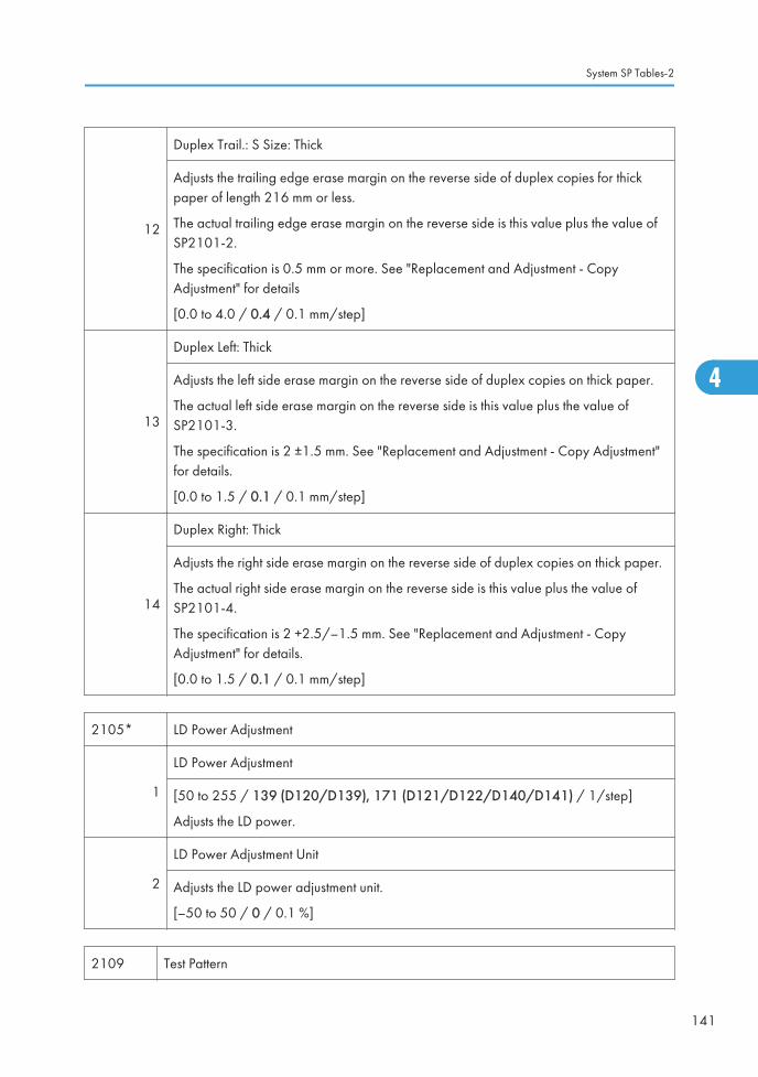
12
Duplex Trail.: S Size: Thick
Adjusts the trailing edge erase margin on the reverse side of duplex copies for thickpaper of length 216 mm or less.
The actual trailing edge erase margin on the reverse side is this value plus the value ofSP2101-2.
The specification is 0.5 mm or more. See "Replacement and Adjustment - CopyAdjustment" for details
[0.0 to 4.0 / 0.4 / 0.1 mm/step]
13
Duplex Left: Thick
Adjusts the left side erase margin on the reverse side of duplex copies on thick paper.
The actual left side erase margin on the reverse side is this value plus the value ofSP2101-3.
The specification is 2 ±1.5 mm. See "Replacement and Adjustment - Copy Adjustment"for details.
[0.0 to 1.5 / 0.1 / 0.1 mm/step]
14
Duplex Right: Thick
Adjusts the right side erase margin on the reverse side of duplex copies on thick paper.
The actual right side erase margin on the reverse side is this value plus the value ofSP2101-4.
The specification is 2 +2.5/–1.5 mm. See "Replacement and Adjustment - CopyAdjustment" for details.
[0.0 to 1.5 / 0.1 / 0.1 mm/step]
2105* LD Power Adjustment
1
LD Power Adjustment
[50 to 255 / 139 (D120/D139), 171 (D121/D122/D140/D141) / 1/step]
Adjusts the LD power.
2
LD Power Adjustment Unit
Adjusts the LD power adjustment unit.
[–50 to 50 / 0 / 0.1 %]
2109 Test Pattern
System SP Tables-2
141
4

1
Pattern Select
Prints the test patterns. Select the number of the test pattern that you want to print. Whenadjusting the printing registration, select no.14 (Trimming Area).
[0 to 21 / 0 / 1 step]
2
Test Pattern Density
Adjusts the test pattern density.
[0 to 15 / 15 / 1 step]
Test Patterns for SP2109
0 None 11 Independent Pattern (1dot)
1 Vertical Line (1 dot) 12 Independent Pattern (2dot)
2 Vertical Line (2dot) 13 Independent Pattern (4dot)
3 Horizontal Line (1dot) 14 Trimming Area
4 Horizontal Line (2 dot) 15 Black Band (Horizontal)
5 Grid Vertical Line 16 Black Band (Vertical)
6 Grid Horizontal Line 17 Checker Flag Pattern
7 Grid Pattern Small 18 Grayscale (Vertical)
8 Grid Pattern Large 19 Grayscale (Horizontal)
9 Argyle Pattern Small 20 Full Dot Pattern
10 Argyle Pattern Large 21 All White Pattern
2201* Development Bias Adjust
1
Printing
Adjusts the development bias during printing.
This can be adjusted as a temporary measure if faint copies appear due to an agingdrum.
[–1500 to 0 / –650 / 10 V/step]
4. Appendix: Service Program Mode Tables
142
4

2
ID Sensor Pattern
Adjusts the development bias for making the ID sensor pattern.
The actual development voltage for the ID sensor pattern is this value plus the value ofSP2201-1.
This should not be used in the field, because it affects ID sensor pattern density, whichaffects toner supply.
[0 = N (200V) / 1 = H (240V) / 2 = L (160V) / 3 = HH (280V) / 4 = LL (120V)]
2210* Bias Off Time
1
Charge Bias
Adjusts the charge voltage (-1200V) application time.
When the charge voltage and development bias are turned off at the same time, toneror carrier will be attracted to the drum. To reduce the toner or carrier attraction, themachine applies –1200V to the charge roller before the development bias is turnedoff. This SP adjusts the time for applying the charge.
[10 to 150 / 100 / 10 ms /step]
2
Development Bias
Adjusts the development bias off time.
[10 to 200 / 80 / 10 ms/step]
2211*
PCU Reverse Interval
Adjusts the PCU reverse interval for cleaning during a job.
When the machine has made this number of copies in the middle of a job, the machinereverses to clean the edge of the cleaning blade. After cleaning, the machine resumesthe job. Set to a shorter interval if thin white lines appear on printouts.
[0 to 999 / 100 / 1 sheet/step]
0: Never cleans during job
2213*
Copies After Toner Near End
Selects the number of copies that can be made after toner near-end has been detected.
[0 = 50 pages / 1 = 20 pages]
If the user normally makes copies with a high proportion of black, reduce the interval.
System SP Tables-2
143
4

2220* Vsg/Vsp/Vsdp/Vt/Vtref Display
1 Vsp
Displays the individual Vsp, Vsg, Vdsp, Vt, and Vtref values.
2 Vsg
3 Vsdp
4 Vt
5 Vtref
2301* Transfer Current Adjust
1*
Thin:1side:Image Area
Adjusts the transfer current for copying.
[–4 to 4/ 0 / 1 A /step]
2*
Thin:1side:Lead Edge
Adjusts the transfer current for copying.
[–4 to 4/ 0 / 1 A /step]
3*
Thin:1side:Trail Edge
Adjusts the transfer current for copying.
[–4 to 4/ 0 / 1 A /step]
4*
Thin:2side:Image Area
Adjusts the transfer current for copying.
[–4 to 4/ 0 / 1 A /step]
5*
Thin:2side:Lead Edge
Adjusts the transfer current for copying.
[–4 to 4/ 0 / 1 A /step]
6*
Thin:2side:Trail Edge
Adjusts the transfer current for copying.
[–4 to 4/ 0 / 1 A /step]
4. Appendix: Service Program Mode Tables
144
4

7*
Plain:1side:Image Area
Adjusts the transfer current for copying.
[–4 to 4/ 0 / 1 A /step]
8*
Plain:1side:Lead Edge
Adjusts the transfer current for copying.
[–4 to 4/ 0 / 1 A /step]
9*
Plain:1side:Trail Edge
Adjusts the transfer current for copying.
[–4 to 4/ 0 / 1 A /step]
10*
Plain:2side:Image Area
Adjusts the transfer current for copying.
[–4 to 4/ 0 / 1 A /step]
11*
Plain:2side:Lead Edge
Adjusts the transfer current for copying.
[–4 to 4/ 0 / 1 A /step]
12*
Plain:2side:Trail Edge
Adjusts the transfer current for copying.
[–4 to 4/ 0 / 1 A /step]
13*
Middle:1side:Image Area
Adjusts the transfer current for copying.
[–4 to 4/ 0 / 1 A /step]
14*
Middle:1side:Lead Edge
Adjusts the transfer current for copying.
[–4 to 4/ 0 / 1 A /step]
15*
Middle:1side:Trail Edge
Adjusts the transfer current for copying.
[–4 to 4/ 0 / 1 A /step]
System SP Tables-2
145
4

16*
Middle:2side:Image Area
Adjusts the transfer current for copying.
[–4 to 4/ 0 / 1 A /step]
17*
Middle:2side:Lead Edge
Adjusts the transfer current for copying.
[–4 to 4/ 0 / 1 A /step]
18*
Middle:2side:Trail Edge
Adjusts the transfer current for copying.
[–4 to 4/ 0 / 1 A /step]
19*
Thick:1side:Image Area
Adjusts the transfer current for copying.
[–4 to 4/ 0 / 1 A /step]
20*
Thick:1side:Lead Edge
Adjusts the transfer current for copying.
[–4 to 4/ 0 / 1 A /step]
21*
Thick:1side:Trail Edge
Adjusts the transfer current for copying.
[–4 to 4/ 0 / 1 A /step]
22
Input:1side
Adjusts the transfer current for copying.
[0 to 30 / 0 / 1 A /step]
23
Input:2side
Adjusts the transfer current for copying.
[0 to 30 / 0 / 1 A /step]
24*
Non Image Area
Adjusts the transfer current for copying.
[0 to 30 / 10 / 1 A /step]
4. Appendix: Service Program Mode Tables
146
4

25*
Temp Inside the Machine
Displays the temperature measured inside the machine just after power-on (by thethermistor on the BCU board) the last time that the fusing unit was less than 40°C justafter the machine was switched on.
The transfer current is corrected in accordance with this value.
[0 to 99 / 20 / 1 A /step]
2302* Transfer Current Switch Timing
1
Transfer Current Switch Timing Lead Edge
Adjusts the transfer current switch timing based on FGATE assert.
[–10 to 10 / 0 / 1 mm]
2
Transfer Current Switch Timing Trail Edge
Adjusts the transfer current switch timing based on FGATE negate.
[–10 to 10 / 0 / 1 mm]
2303* Transfer Roller Cleaning Bias
1
Positive
Adjusts the positive current of the paper transfer roller for cleaning the paper transferroller.
[0 to 20 / 10 / 1 A]
2
Negative
Adjusts the negative current of the paper transfer roller for cleaning the paper transferroller.
[0 to 20 / 4 / 1 A]
2801
Developer Initialization
Initializes the developer and resets the TD and ID sensor outputs to their defaults. Dothis SP after you fill the PCU with developer at machine installation and every timedeveloper is replaced.
System SP Tables-2
147
4

2802
Developer Mixing
Mixes the developer and checks Vt. The machine mixes the developer for 2 minutesand while doing this, it reads the TD sensor output (Vt). It does not initialize the TDsensor output.
If the machine has not been used for a long time, prints may have a dirty background.In this case, use this SP mode to mix the developer.
2803* Developer Initialization Data
1
Vtref
When the machine detects a new PCU (photoconductor unit) in the machine, it checksthe heat seals at the creation of the first ID sensor pattern. After the agitator is rotatedfor 30 sec., the machine creates the second ID sensor pattern and corrects thereference value of the TD sensor. The corrected reference value for the TD sensor isrecorded here.
2ID Sensor PWM Value
Displays the PWM value of the ID sensor after performing the developer initialization.
2901* Separation Voltage Adjust
1
1side:Lead Edge
Adjusts the voltage that is applied to the separation plate during printing at the leadingedge of the paper on the front side.
If the copies have pawl marks at the leading edge, increase this voltage.
[–4000 to 0 / –1800 / 100 V/step]
2
1side:Image Area
Adjusts the voltage that is applied to the separation plate during printing on the imagearea of the paper on the front side.
If the copies have pawl marks in the image area, increase this voltage.
[–4000 to 0 / –1800 / 100 V/step]
4. Appendix: Service Program Mode Tables
148
4

3
2side:Lead Edge
Adjusts the voltage applied to the separation plate, during printing at the leading edgeof the paper on the rear side.
See SP2901 1.
[–4000 to 0 / –2100 / 100 V/step]
4
2side:Image Area
Adjusts the voltage applied to the separation plate, during printing at the image area ofthe paper on the rear side.
See SP2901 2.
[–4000 to 0 / –2100 / 100 V/step]
5
Switching Timing Lead Edge
Adjusts the separation voltage switch timing based on FGATE assert.
[-20 to 20 / 15 / 1 mm]
2906* Tailing Control
1
Shift Range
Shifts the image across the page at the interval specified by SP2906 2.
When making many copies of an original that contains vertical lines (such as a table),separation may not work correctly, then a tailing image will occur (ghosts of the verticallines will continue past the bottom of the table). This SP prevents this problem.
[0.0 to 1.0 / 0.0 / 0.1 mm/step]
2
Number of Sheets
Changes the interval for the image shift specified by SP2906 1.
[0 to 10 / 0 / 1 page/step]
2907*
Filter Setting
Adjusts the line width for the copy mode. The default setting disables this function. Anumber smaller than the default makes lines thinner, a number larger than the defaultmakes lines thicker.
1 Text: Multilevel Copy [0 to 10 / 6 / 1 step]
2 Photo: Multilevel Copy [0 to 10 / 5 / 1 step]
System SP Tables-2
149
4

3 Text/Photo: Multilevel Copy
[0 to 10 / 5 / 1 step]4 Pale: Multilevel Copy
5 Generation: Multilevel Copy
2908
Forced Toner Supply
Forces the toner bottle to supply toner to the toner supply unit.
Press Execute on the touch panel to start.
During this process, the machine supplies toner until the toner concentration in thedevelopment unit reaches a standard level. However, if the toner concentration doesnot reach a standard level, the machine supplies toner for 2 minutes maximum.
2915*
Polygon Motor Idling Time
Selects the polygon motor idling time.
The polygon motor starts rotating up to its operation speed if the user 1) sets anoriginal, 2) touches a key, or 3) opens the platen cover or document feeder. Thisshortens the time to the first copy. However, with the default (10 s) set, the motor stopsif the user does nothing for 10 s after doing one of the actions above, and stops 10 s atthe end of a job.
Note: If set at "0", the polygon motor never turns off during stand-by. However, whenthe machine goes into energy saver mode, the polygon motor turns off regardless ofthis timer.
1 Idling Time ADJ [0 to 60/15/1]
2 Post Idling Time ADJ [0 to 60/10/1]
2921*
Toner Supply Mode
Selects the toner supply mode.
[0 = Normal 1 / 1 = Normal 2 / 2 = Fixed 1 / 3 = Fixed 2]
Normally, only use setting 0. Change to 3 temporarily if the TD sensor is defective. Donot use settings 1 and 2; these are for designer's use only.
4. Appendix: Service Program Mode Tables
150
4

2922*
Toner Supply Time
Adjusts the toner supply motor on time for sensor supply mode.
This SP is effective only when SP2921 is "0" or "1".
[0.1 to 5.0 / 0.6 / 0.1 s/step]
Increasing this value increases the toner supply motor on time. So, use a high value ifthe user tends to make lots of copies that have a high proportion of black.
2923*
Toner Recovery Time
Adjusts the toner supply motor on time during recovery from toner near-end/end.
This SP is effective only when SP2921 is "0", "1", or "2".
[1 to 60 / 30 / 1 s/step]
Note that toner recovery is done in a 3-second cycle. So, the input value should be amultiple of 3 (e.g. 3, 6, 9). See "Toner Density Control" for more details.
2925*
Toner Supply Ratio
Adjusts the toner supply rate for fixed toner supply mode.
This SP is effective only when SP2921 is "2" or "3".
Increasing this value increases the toner supply motor on time. So, use a high value ifthe user tends to make lots of copies that have a high proportion of black. See "TonerDensity Control" for more details.
[0 to 7 / 0 / 1/step]
0: t, 1: 2t, 2: 4t, 3: 8t, 4: 12t, 5: 16t, 6: On continuously, 7: 0 s
t: 200 ms
2926*
Standard Vt DFU
Adjusts Vts (Vt for a new PCU). The TD sensor output is adjusted to this value during theTD sensor initial setting process. This SP is effective only when SP2921 is "0", "1", or"2".
[0.00 to 5.00 / 2.50 / 0.05 V/step]
System SP Tables-2
151
4

2927*
ID Sensor Control
Selects whether the ID sensor is used or not for toner density control.
[0 = No / 1 = Yes]
If this value is "0", dirty background may occur after the machine has not been used fora long time.
2928
Toner End Clear
Clears the toner end condition. Press Execute on the touch panel to clear the toner endcondition without adding new toner.
When you press Execute, the following are cleared:
• Toner end indicator (goes out)
• Toner near-end counter
• Toner near-end level
When making a lot of copies after changing this setting to "1", the carrier may beattracted to the drum when the toner runs out, which may damage the drum.
2929* Vref Adjustment
1Upper Limit
Adjusts the upper limit for Vref. [0.5 to 3.5 / 3.10 / 0.05 V/step]
2Lower Limit
Adjusts the lower limit for Vref. [0.5 to 3.5 / 1.40 / 0.05 V/step]
2930*
TD Sensor Manual Setting
Adjusts the TD sensor output.
[0 to 5 / 0.0V / 0.05V/step]
2931*
TD (V/wt%) Setting
Adjusts the TD sensor sensitivity (coefficient: S) for toner density control.
[0.01 to 1.50 / 0.4 / 0.01/step]
4. Appendix: Service Program Mode Tables
152
4

2932*
Toner Density Control Level
Adjusts the toner density control threshold level.
[0 = Normal / 1 = Dark / 2 = Light / 3 = Darker / 4 = Lighter]
Use this SP when you want to adjust the image density.
2933*
ID Sensor Control Correction
Adjusts the ID sensor control coefficient.
[0.5 to 3 / 1 / 0.1/step]
2934* ID Sensor PWM Setting
1 Display Displays the PWM of the ID Sensor LED.
3 Upper Limit Correction
Corrects the upper limit of the PWM for the IDsensor LED.
[0 to 1023 / 100 / 1/step]
2935
ID Sensor Initialization
Performs the ID sensor initial setting.
Press Execute on the touch panel to start. Perform this setting after replacing or cleaningthe ID sensor.
2992*
Copies After TD Sensor Error
Selects the number of copies that can be made after a TD sensor error has beendetected. When the machine copies this amount, an SC condition will occur. If theoptional fax unit is installed, the SC condition occurs immediately regardless of thenumber of prints (this is because the sender of the fax cannot check the image quality ofthe printout).
[0 or 1 / 0 / -]
0:100 Pages, 1:200 Pages
2995* ID Sensor Detection Interval
System SP Tables-2
153
4

1
Warming-up
If the period of time specified here elapses before the machine returns to full operationfrom the energy saver or auto off mode, ID sensor warming-up is performed.
[0 to 999 / 480 / 1 min]
2
Number of Pages
The machine makes an ID sensor pattern after the specified number of prints has beenmade.
[0 to 999 / 300 / 1 sheet/step]
3
Job End/Interrupt
Determines when the ID sensor reads the ID sensor pattern.
[0 or 1 / 0 / -]
0: Job End. Read pattern at job end.
1: Interrupt. Read pattern at interval set with SP2995-2, even if the job is notcompleted.
2996*Transfer Roller Cleaning
These SP codes determine how the transfer roller is cleaned.
1
0:OFF 1:ON
Selects whether the transfer roller is cleaned. Transfer roller cleaning is necessary onlywhen black spots occur in the image areas of copies. This can occur when badenvironmental conditions increase the toner density.
Set this to "1" when dirty background appears on the reverse side of the first page of acopy job. However, the first copy time will be longer regardless of the SP2996 001setting.
[0 = No / 1 = Yes]
4. Appendix: Service Program Mode Tables
154
4

2
Interval
This SP sets the page interval for transfer roller cleaning when SP2996 001 is set to "1"(Yes). Increase this setting only when absolutely necessary. A higher setting increaseswear on the PCU.
[0to100/50/1 sheets]
Note: This SP does not execute for the first copy after power on or when the machinereturns from the energy save or auto off mode.
This SP setting does cannot correct poor copies if there is a problem with the TD sensor.
2998* PCU Reverse Rotation Time
1
Wait Time
Adjusts the waiting time for starting to rotate the drum in reverse after the end of eachjob. The wait time calculation formula is as follows.
[0 to 999 / 300 / 1]
This SP is adjusted in units of 30 ms (1 step = 30 ms, 2 steps = 60 ms, etc.)
If "0" is selected, the drum reverses immediately at the end of the job.
2
Reverse Time
Adjusts the drum reverse rotation time.
[0 to 99 / 60 / 1]
This SP is adjusted in units of 60 ms (1 step = 6 ms, 2 steps = 12 ms, etc.)
If "0" is selected, the drum does not reverse at the end of the job.
3
Brake Time
Adjusts the length of time of braking to stop reverse rotation of the drum.: DFU
[0 to 99/0/1]
This SP is adjusted in units of 6 ms (1 step = 6 ms, 2 steps = 12 ms, etc.)
If "0" is selected, the drum stops reverse rotation immediately.
System SP Tables-2
155
4

System SP Tables-3
SP3xxx
There are no Group 3 SP codes for this machine.
4. Appendix: Service Program Mode Tables
156
4

System SP Tables-4
SP4xxx: Scanner
4008*
Sub Scan Mag.Adjustment
Adjusts the magnification of the sub scan direction during scanning. Changing thisvalue changes the scanner motor speed. Press to toggle ±.
[–1 to 1 / 0 / 0.1% ]
4010*
L-Edge Regist Adjustment
Adjusts the leading edge registration for scanning. Press to toggle ±.
[–2 to 2 / 0 / 0.1 mm ]
As you enter a negative value, the image moves toward the leading edge.
4011*
S-to-S Regist Adjustment
Adjusts side-to-side registration for scanning. Press to toggle ±.
[–2.5 to +2.5 / 0.0 / 0.1 mm step]
As you enter negative values, the image will disappear at the left, and as you enterpositive values, the image will appear at the left.
4012*
Scanner Erase Margin: Scale
Adjusts the erase margin at each side for scanning in book mode and ADF mode.
• Do not adjust this unless the user wishes to have a scanner margin that is greaterthan the printer margin.
• These settings are adjusted to erase shadows caused by the gap between theoriginal and the scale of the scanner unit.
1 Book: Leading Edge [0 to 3.0 / 1.0 / 0.1 mm / step]
2 Book: Trailing Edge [0 to 3.0 / 0.0 / 0.1 mm / step]
3 Book: Left [0 to 3.0 / 1.0 / 0.1 mm / step]
System SP Tables-4
157
4

4 Book: Right
[0 to 3.0 / 0.0 / 0.1 mm / step]5 ADF: Leading Edge
7 ADF: Right
8 ADF: Left
4013Scanner Free Run
Performs a scanner free run with the exposure lamp on or off.
1 Lamp OFF [0 to 1 / 0 / 1]
0=Off, 1=On2 Lamp ON
4014Scan
Performs a scanner free run with or without HP sensor check.
1 HP Detection Enable • Touch [Execute] to start this feature.
• Press the (Clear/Stop) key to stop.2 HP Detection Disable
4020
Dust Check
This function checks the narrow scanning glass of the ADF for dust that can cause blacklines in copies. If dust is detected a system banner message is displayed, but processingdoes not stop.
1
Dust Detect:On/Off
Issues a warning if there is dust on the narrow scanning glass of the ADF when theoriginal size is detected before a job starts. This function can detect dust on the whiteplate above the scanning glass, as well as dust on the glass. Sensitivity of the level ofdetection is adjusted with SP4020 2.
[0 to 1 / 1 / 1]
0: Off. No dust warning.
1: On. Dust warning. This warning does not stop the job.
• Before switching this setting on, clean the ADF scanning glass and the white plateabove the scanning glass.
4. Appendix: Service Program Mode Tables
158
4

2
Dust Detect:Lvl
Adjusts the sensitivity for dust detection on the ADF scanning glass. This SP is availableonly after SP4020 1 is switched on.
[0 to 8 / 4 / 1]
If you see black streaks in copies when no warning has been issued, raise the setting toincrease the level of sensitivity. If warnings are issued when you see not black streaks incopies, lower the setting.
Note: Dust that triggers a warning could be removed from the glass by the originals inthe feed path. If the dust is removed by passing originals, this is not detected and thewarning remains on.
3
Dust Reject:Lvl
Selects the level of the sub scan line correction when using the ARDF.
[0 to 4 / 0 / 1 /step]
0: Off, 1: Weakest, 2: Weak, 3: Strong, 4: Strongest
4301APS Operation Check
Displays the status of the APS sensors and platen/DF cover sensor.
4303*
APS Min. Size
Selects if the copier defaults to A5 SEF/LEF if the APS sensor cannot detect the size of asmall original.
[0 to 1/ 0 /1]
0: No Original (Not detected as A5)
1: A5-Lengthwise (Detected as A5 SEF)
4305*
8K/16K Detection
Selects whether the machine determines that the original is A4/LT, or 8K/16K.
8K/16K is not available for USA models.
[0 = Normal (LT for USA models, A4 for Europe/Asia models)
1 = A4-Sideways LT-Lengthwise
2 = LT-Sideways A4-Lengthwise
3 = 8K/16K]
System SP Tables-4
159
4

4308*
Scan Size Detection Detection ON/OFF
Selects whether the machine detects the original size.
[0 to 1 / 1 / 1]
0: Off, 1: On
4309* Scan Size Detect:Setting
1 Original Density Thresh [0 to 255 / 18 / 1 digit]
2 Detection Time [20 to 100 / 60 / 20 msec]
3 Lamp ON:Delay Time [0 to 200 / 40 / 20 msec]
4 LED PWM Duty [0 to 100 / 60 / 1 %]
4310
Scan Size Detect Value
Displays the detected value by CCD. Each detection point for paper size and color isdisplayed on the LCD.
1 S1:R
[0 to 255 / 0 / 1 digit]
2 S1:G
3 S1:B
4 S2:R
5 S2:G
6 S2:B
7 S3:R
8 S3:G
9 S3:B
• Each detection point (S1, S2, S3) in SP4310 is as follows.
4. Appendix: Service Program Mode Tables
160
4
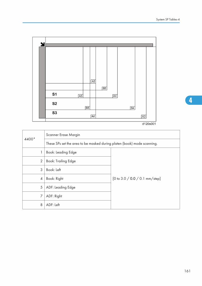
4400*Scanner Erase Margin
These SPs set the area to be masked during platen (book) mode scanning.
1 Book: Leading Edge
[0 to 3.0 / 0.0 / 0.1 mm/step]
2 Book: Trailing Edge
3 Book: Left
4 Book: Right
5 ADF: Leading Edge
7 ADF: Right
8 ADF: Left
System SP Tables-4
161
4

4417
IPU Test Pattern
Selects the IPU test Pattern.
Test PatternSelection
[0 to 28 / 0 / 1]
0: Scanned image 15: Gray pattern (1)
1: Gradation main scan A 16: Gray pattern (2)
2: Gradation main scan B 17: Gray pattern (3)
3: Gradation main scan C 18: Shading pattern
4: Gradation main scan D 19: Thin line pattern
5: Gradation sub scan (1) 20: Scanned + Grid pattern
6: Grid pattern (1) 21: Scanned + Grid scale
7: Slant grid pattern 22: Scanned + Color patch
8: Gradation K 23: Scanned + Slant Grid C
9: Check pattern 16 24: Scanned + Slant Grid D
10: Gray patch 16 (1) 25: Gray Scale 18 text
11: Gray patch 16 (2) 26: Gray Scale 18 photo
12: Gray patch 64 27: Gray Scale 256 text
13: Grid pattern (2) 28: Gray Scale 256 photo
14: Color patch K
4429*Select Copy Data Security
Adjusts the ICI density level.
1 Copying
[0 to 3 / 3 / 1 /step]2 Scanning
3 Fax Operation
4450Scan Image Path Selection
Determines the method of image path detection.
4. Appendix: Service Program Mode Tables
162
4

1 Black Subtraction ON/OFFSwitches black image path detection on/off:
0: ON, 1: OFF
2 SH ON/OFFSwitches shading image path detection on/off
0: OFF, 1: ON
4460*Digital AE Set
Specifies the detection threshold for background deletion in ADS mode.
1 Low Limit [0 to 1023 / 364 / 1 digit]
2 Background Level [512 to 1535 / 932 / 1 digit/step]
4550* Scan Apli:Txt/Print
4551* Scan Apli:Txt
4552* Scan Apli:Txt Dropout
4553* Scan Apli:Txt/Photo
4554* Scan Apli:Photo
4565* Scan Apli:GrayScale
4570* Scan Apli:Col Txt/Photo
4571* Scan Apli:Col Gloss Photo
4572* Scan Apli:AutoCol
5
MTF: 0(Off) 1-15 (Weak-Strong)
[0 to 15 / 8 / 1 /step]
0: MTF Off
When the CCD converts the original image to electrical signals, the contrast is reduceddue to the influence that adjacent white and black pixels have on one another as aresult of lens properties. Typically, you may see very narrow width and spacingbetween black and white areas. MTF corrects this problem and emphasizes imagedetail.
System SP Tables-4
163
4

6 Smoothing
Selects the level of smoothing for originals that contain ditheredimages.
[0 to 7 / 4 / 1 / step]
0: Default (Off) 7: Strongest
7 Brightness
Sets the overall brightness of the image.
[1 to 255/ 128 / 1 / step]
1: Weakest 128: Default 255: Strongest
8 Contrast
Sets the overall contrast of the image.
[1 to 255/ 128 / 1 / step]
1: Weakest 128: Default 255: Strongest
9 Ind. Dot Erase
Sets the level of independent dot erasure to improve the appearanceof background.
[0 to 7/ 0 / 1 / step]
0: Default (Off) 7: Strongest
4580* Fax Apli:Txt/Chart
4581* Fax Apli:Txt
4582* Fax Apli:Txt/Photo
4583* Fax Apli:Photo
4584* Fax Apli:Original 1
4585* Fax Apli:Original 2
5
MTF: 0(Off) 1-15 (Weak-Strong)
[0 to 15 / 8 / 1 /step]
0: MTF Off
When the CCD converts the original image to electrical signals, the contrast is reduceddue to the influence that adjacent white and black pixels have on one another as aresult of lens properties. Typically, you will see very narrow width and spacingbetween black and white areas. MTF corrects this problem and emphasizes imagedetail.
4. Appendix: Service Program Mode Tables
164
4

6 Smoothing
Selects the level of smoothing for originals that contain ditheredimages.
[0 to 7 / 4 / 0 / step]
0: Default (Off) 7: Strongest
7 Brightness
Sets the overall brightness of the image.
[1 to 255/ 128 /1]
1: Weakest 128: Default 255: Strongest
8 Contrast
Sets the overall contrast of the image.
[1 to 255/ 128 /1]
1: Weakest 128: Default 255: Strongest
9 Ind. Dot Erase
Sets the level of independent dot erasure to improve theappearance of background.
[0 to 7/ 0 / 1 /step]
0: Default (Off) 7: Strongest
10 Text Erasure
Sets the erasure level of textures. Set higher for stronger effect,lower for weaker effect.
[0 to 2 / 0 / 1 /step]
0: Not activated
Note: This SP code exists for SP4580, SP4582 and SP4583only.
4600SBU Version Display
Displays the version number of the SBU.
1 SBU ID [0 to 0xFF / 0 / 1]
2 GASBU-N ID [0 to 0xFF / 0 / 1]
3 VSP5100 ID [0 to 0xFF / 0 / 1]
4602 Scanner Memory Access
1 Scanner Memory AccessEnables the read and write check for the SBUregisters.
System SP Tables-4
165
4

4603AGC Execution
Executes the AGC.
1 HP Detection Enable
2 HP Detection Disable
4604
FGATE Open/Close
Opens or closes the FGATE signal. This SP automatically returns to the default status(close) after exiting this SP.
[0 or 1 / 0 / 1 / step]
0: OFF, 1: ON
Note:
• When the registration sensor goes ON, the BCU generates the FGATE signal andsends it to the LD units.
• As soon as the LD units receive the FGATE signal, they send a feedback signal tothe BCU.
• SC230, SC231 if the FGATE signal fails to switch on or off.
4609*Gray Balance Set: R
Adjusts the gray balance of the red signal for each scanning mode.
1 Book Scan[-384 to 255 / -46 / 1 digit ]
2 DF Scan
4610Gray Balance Set: G
Adjusts the gray balance of the green signal for each scanning mode.
1 Book Scan[-384 to 255 / -20 / 1 digit ]
2 DF Scan
4611*Gray Balance Set: B
Adjusts the gray balance of the blue signal for each scanning mode.
4. Appendix: Service Program Mode Tables
166
4

1 Book Scan[-384 to 255 / -28 / 1 digit ]
2 DF Scan
4623
Black Level Adj. Display
Note:
• RE: Red Even signal
• RO: Red Odd signal
1 Latest: RE Color
Displays the black offset value for the even red signal inthe CCD circuit board.
[0 to 16383 / 0 / 1 digit/step]
2 Latest: RO Color
Displays the black offset value for the odd red signal in theCCD circuit board.
[0 to 16383 / 0 / 1 digit/step]
4624
Black Level Adj. Display
Note:
• GE: Green Even signal
• GO: Green Odd signal
1 Latest: GE Color
Displays the black offset value for the even green signal inthe CCD circuit board.
[0 to 16383 / 0 / 1 digit/step]
2 Latest: GO Color
Displays the black offset value for the odd green signal inthe CCD circuit board.
[0 to 16383 / 0 / 1 digit/step]
4625
Black Level Adj. Display
Note:
• BE: Blue Even signal
• BO: Blue Odd signal
1 Latest: BE Color
Displays the black offset value for the even blue signal inthe CCD circuit board.
[0 to 16383 / 0 / 1 digit/step]
System SP Tables-4
167
4

2 Latest: BO Color
Displays the black offset value for the odd blue signal inthe CCD circuit board.
[0 to 16383 / 0 / 1 digit/step]
4628
Analog Gain Adjust Latest: R Color
Displays the gain value of the amplifiers on the controller for Red.
[0 to 7 / 0 / 1 digit/step]
4629
Analog Gain Adjust Latest: G Color
Displays the gain value of the amplifiers on the controller for Green.
[0 to 7 / 0 / 1 digit/step]
4630
Analog Gain Adjust Latest: B Color
Displays the gain value of the amplifiers on the controller for Blue.
[0 to 7 / 0 / 1 digit/step]
4631Digital Gain Adjust
Displays the gain value of the amplifiers on the controller for Red.
1 Latest: RE Color[0 to 1023 / 0 / 1 digit ]
2 Latest: RO Color
4632Digital Gain Adjust
Displays the gain value of the amplifiers on the controller for Green.
1 Latest: GE Color[0 to 1023 / 0 / 1 digit ]
2 Latest: GO Color
4633Digital Gain Adjust
Displays the gain value of the amplifiers on the controller for Blue.
1 Latest: BE Color[0 to 1023 / 0 / 1 digit ]
2 Latest: BO Color
4. Appendix: Service Program Mode Tables
168
4

4645Scan Adjust Error
Displays the error value of the white level or black level adjustment.
1 White Level[0 to 65535 / 0 / 1 digit ]
2 Black Level
4647SBU Error
Displays the result of the SBU connection check.
4654*Black Level Adj. Display
RE: Red Even signal, RO: Red Odd signal
1Last Correct Value: REColor
Displays the previous black offset value for the even redsignal in the CCD circuit board.
[0 to 16383 / 0 / 1 digit/step]
2Last Correct Value: ROColor
Displays the previous black offset value for the odd redsignal in the CCD circuit board.
[0 to 16383 / 0 / 1 digit/step]
4655*Black Level Adj. Display
GE: Green Even signal, GO: Green Odd signal
1Last Correct Value: GEColor
Displays the previous black offset value for the even greensignal in the CCD circuit board.
[0 to 16383 / 0 / 1 digit/step]
2Last Correct Value: GOColor
Displays the previous black offset value for the odd greensignal in the CCD circuit board.
[0 to 16383 / 0 / 1 digit/step]
4656*Black Level Adj. Display
BE: Blue Even signal, BO: Blue Odd signal
1Last Correct Value: BEColor
Displays the previous black offset value for the even bluesignal in the CCD circuit board.
[0 to 16383 / 0 / 1 digit/step]
System SP Tables-4
169
4

2Last Correct Value: BOColor
Displays the previous black offset value for the odd bluesignal in the CCD circuit board.
[0 to 16383 / 0 / 1 digit/step]
4658*
Analog Gain Adjust Last Correct Value: R Color
Displays the previous gain value of the amplifiers on the controller for Red.
[0 to 7 / 0 / 1 digit/step]
4659*
Analog Gain Adjust Last Correct Value: G Color
Displays the previous gain value of the amplifiers on the controller for Green.
[0 to 7 / 0 / 1 digit/step]
4660*
Analog Gain Adjust Last Correct Value: B Color
Displays the previous gain value of the amplifiers on the controller for Blue.
[0 to 7 / 0 / 1 digit/step]
4661*Digital Gain Adjust
RE: Red Even signal, RO: Red Odd signal
1Last Correct Value: REColor
Displays the previous 2nd black offset value for the evenred signal in the CCD circuit board.
[0 to 1023 / 0 / 1 digit/step]
2Last Correct Value: ROColor
Displays the previous 2nd black offset value for the oddred signal in the CCD circuit board.
[0 to 1023 / 0 / 1 digit/step]
4662*Digital Gain Adjust
GE: Green Even signal, GO: Green Odd signal
1Last Correct Value: GEColor
Displays the previous 2nd black offset value for the evengreen signal in the CCD circuit board.
[0 to 1023 / 0 / 1 digit/step]
4. Appendix: Service Program Mode Tables
170
4

2Last Correct Value: GOColor
Displays the previous 2nd black offset value for the oddgreen signal in the CCD circuit board.
[0 to 1023 / 0 / 1 digit/step]
4663*Digital Gain Adjust
BE: Blue Even signal, BO: Blue Odd signal
1Last Correct Value: BEColor
Displays the previous 2nd black offset value for the evenblue signal in the CCD circuit board.
[0 to 1023 / 0 / 1 digit/step]
2Last Correct Value: BOColor
Displays the previous 2nd black offset value for the oddblue signal in the CCD circuit board.
[0 to 1023 / 0 / 1 digit/step]
4673*Black Level Adj. Display DFU
RE: Red Even signal, RO: Red Odd signal
1 Factory Setting: RE ColorDisplays the factory setting values of the black leveladjustment for the even red signal in the CCD circuitboard.
2 Factory Setting: RO ColorDisplays the factory setting values of the black leveladjustment for the odd red signal in the CCD circuit board.
4674*Black Level Adj. Display DFU
GE: Green Even signal, GO: Green Odd signal
1 Factory Setting: GE ColorDisplays the factory setting values of the black leveladjustment for the even green signal in the CCD circuitboard.
2 Factory Setting: GO ColorDisplays the factory setting values of the black leveladjustment for the odd green signal in the CCD circuitboard.
4675*Black Level Adj. Display DFU
BE: Blue Even signal, BO: Blue Odd signal
System SP Tables-4
171
4

1 Factory Setting: BE ColorDisplays the factory setting values of the black leveladjustment for the even blue signal in the CCD circuitboard.
2 Factory Setting: BO ColorDisplays the factory setting values of the black leveladjustment for the odd blue signal in the CCD circuitboard.
4677*Analog Gain Adjust Factory Setting: R Color DFU
Displays the factory setting values of the gain adjustment for Red.
4678*Analog Gain Adjust Factory Setting: G Color DFU
Displays the factory setting values of the gain adjustment for Green.
4679*Analog Gain Adjust Factory Setting: B Color DFU
Displays the factory setting values of the gain adjustment for Blue.
4680*Digital Gain Adjust DFU
Displays the gain value of the amplifiers on the controller for Red.
1 Factory Setting: RE Color
2 Factory Setting: RO Color
4681*Digital Gain Adjust DFU
Displays the gain value of the amplifiers on the controller for Green.
1 Factory Setting: GE Color
2 Factory Setting: GO Color
4682*Digital Gain Adjust DFU
Displays the gain value of the amplifiers on the controller for Blue.
1 Factory Setting: BE Color
2 Factory Setting: BO Color
4. Appendix: Service Program Mode Tables
172
4

4688*
Scan Image Density Adjustment ARDF
Adjusts the white shading parameter when scanning an image with the DF. Adjusts thedensity level if the ID of outputs made in the DF and Platen mode is different.
[80 to 120 / 104 / 1%/ step ]
4690White Peak Level Read DFU
Displays the peak level of the white level scanning.
1 RE
2 RO
4691White Peak Level Read DFU
Displays the peak level of the white level scanning.
1 GE
2 GO
4692White Peak Level Read DFU
Displays the peak level of the white level scanning.
1 BE
2 BO
4693Black Peak Level Read DFU
Displays the peak level of the black level scanning.
1 RE
2 RO
4694Black Peak Level Read DFU
Display the peak level of the black level scanning.
1 GE
2 GO
System SP Tables-4
173
4

4695Black Peak Level Read DFU
Display the peak level of the black level scanning.
1 BE
2 BO
4802
DF Shading Free Run
Executes the scanner free run for shading movement with the exposure lamp on or off.The free run moves the scanning lamp a short distance and immediately returns it to itshome position.
1 Lamp OFF • Touch [ON] to start the free run
• Be sure to touch "OFF" to stop the free run.2 Lamp ON
4804
Home Position
Moves the exposure lamp a short distance and immediately returns it to its homeposition. Touch [Execute]> "Completed"> [Exit].
4806
Carriage Save
Moves the exposure lamp a short distance away from the home position and stops.
• Touch [Execute]> "Completed"> [Exit]
• Do SP4804 to return the exposure lamp to its home position.
Note
• This SP is done before shipping the machine to another location.
• Turning the machine power off/on also returns the exposure lamp to its homeposition.
4807 SBU Test Pattern Change
4. Appendix: Service Program Mode Tables
174
4

Selects the test pattern generated by the controller board.
[0 to 255 / 0 / 1 /step]
0: Default (Scanning Image)
1: Grid pattern
2: Gradation main scan
3: Gradation sub scan
4 to 255: Default (Scanning Image)
4810 PWM DFU
4811 LED White Level Peak Read DFU
4812 LED White Level Peak Read DFU
4903*
Filter Setting
This SP code sets the threshold value for independent dot erase.
• The "0" setting disables independent dot erase.
• A higher setting detects more spurious dots for erasing. However, this could causedots to erase in images that contain areas filled by dithering.
1 Ind Dot Erase: Text[0 to 7/ 0 /1]
2 Ind Dot Erase: Generation Copy
4905*
Select Gradation Level
Changes the parameters for dithering.
[0 to 255 / 0 / 1 /step]
4906*Filter Setting: Other DFU
Outline level Adj [0 to 10 / 0 / 1]
4918 Manual Gamma Adjustment DFU
4954* Read/Restore Std
System SP Tables-4
175
4
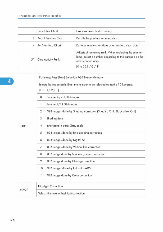
1 Scan New Chart Executes new chart scanning.
2 Recall Previous Chart Recalls the previous scanned chart.
4 Set Standard Chart Restores a new chart data as a standard chart data.
5* Chromaticity Rank
Adjusts chromaticity rank. When replacing the scannerlamp, select a number according to the barcode on thenew scanner lamp.
[0 to 255 / 0 / 1]
4991
IPU Image Pass [Path] Selection RGB Frame Memory
Selects the image path. Enter the number to be selected using the 10-key pad.
[0 to 11/ 2 / 1]
0 Scanner input RGB images
1 Scanner I/F RGB images
2 RGB images done by Shading correction (Shading ON, Black offset ON)
3 Shading data
4 Inner pattern data: Gray scale
5 RGB images done by Line skipping correction
6 RGB images done by Digital AE
7 RGB images done by Vertical line correction
8 RGB image done by Scanner gamma correction
9 RGB image done by Filtering correction
10 RGB images done by Full color ADS
11 RGB image done by Color correction
4993*Highlight Correction
Selects the level of highlight correction.
4. Appendix: Service Program Mode Tables
176
4

1 Sensitivity Selection
Selects the Highlight correction level.
[0 to 9 / 4 / 1 /step]
0: weakest sensitivity
9: strongest sensitivity
2 Range Selection
Selects the range level of Highlight correction.
[0 to 9 / 4 / 1 /step]
0: weakest skew correction,
9: strongest skew correction
4994*
Text/Photo Detection Level Adj. High Compression PDF
Selects the definition level between Text and Photo for high compression PDF.
[0 to 2 / 1 / 1 /step]
0: Text priority
1: Normal
2: Photo priority
4996*
White Paper Detection Level
Selects the threshold level of the original background density.
[0 to 6 / 3 / 1/step]
0: Lightest
6: Darkest
System SP Tables-4
177
4

System SP Tables-5
SP5xxx: Mode
5024*
mm/inch Display Selection
Selects whether mm or inches are used in the display.
Note: After selecting the number, you must turn the main power switch off and on.
[0-1 / Europe/Asia model: 0, American model: 1 / 1]
0: mm
1: inch
5045*
Accounting Counter
Selects whether the printer counter is displayed on the LCD.
[0-1 / 0 / 1]
0: Displays the total counter only.
1: Displays both total counter and printer counter.
5047*
Paper Display
Determines whether the tray loaded with paper printed on one side is displayed.
[0 to 1 / 0 / 1]
0: Not displayed
1: Displayed
5052*
Return Time Priority Type
Select the priority to return to the stand-by mode.
[0 to 1 / 0 / 1]
0: Energy Save have priority
1: Return time have priority
4. Appendix: Service Program Mode Tables
178
4

5055*
Display IP Address
Display or does not display the IP address on the LCD.
[0 to 1 / 0 / 1]
0: OFF, 1: ON
5056*
Coverage Counter Display
Display or does not display the coverage counter on the LCD.
[0 to 1 / 0 / 1]
0: Not displayed, 1: Displayed
5061*
Toner Remaining Icon Display Change
Display or does not display the remaining toner display icon on the LCD.
[0 to 1 / 0 / 1]
0: Not displayed, 1: Displayed
5062*
Parts PM System Setting
Display or does not display the PM part yield on the LCD.
[0 to 1 / 0 / 1]
0: Not displayed, 1: Displayed
1 PCU
5066* Parts PM Display Setting DFU
5067*
Parts PM System Setting
Selects the service maintenance or user maintenance for each PM parts.
If the user service is selected, PM alert is displayed on the LCD.
[0 to 1 / 0 / 1]
0: Service, 1: User
1 PCU
System SP Tables-5
179
4

5071
Set Bypass Paper Size
Turn on or off the paper size confirmation pop-up on the LED. This pop-up preventsmismatching between a paper size selected by the operation panel and an actualpaper size on the by-pass tray.
[0 to 1 / 0 / 1]
0: Off, 1: On
1 PCU
5104*
A3/DLT Double Count (SSP)
Specifies whether the counter is doubled for A3/DLT. "Yes" counts except from thebypass tray. When "Yes" is selected, A3 and DLT paper are counted twice, that is A4x2 and LT x2 respectively.
5113* Optional Counter Type
1
Default Optional Counter Type
Selects the type of counter:
0: None
1: Key Card (RK3, 4) Japan only
2: Key Card Down
3: Pre-paid Card
4: Coin Lock
5: MF Key Card (Must be enabled with SP5114)
11: Exp Key Card (Add)
12: Exp Key Card (Deduct)
5114* Optional Counter I/F
1
MF Key Card Extension
Use this SP to change the setting to "1" only when the "5" (MF Key Card) is selectedwith SP5113-001.
[0: Not installed/ 1: Installed (scanning accounting)]
4. Appendix: Service Program Mode Tables
180
4

5118*
Disable Copying
This program disables copying.
[0: Not disabled/ 1: Disabled]
5120*
Mode Clear Opt. Counter Removal
This program disables copying.
[0: Yes (removed)/ 1: Standby (installed but not used)/ 2: No (not removed)]
5121*
Counter Up Timing
Determines whether the optional key counter counts up at paper feed-in or at paperexit.
[0 or 1 / 0 / 1 ]
0: Feed
1: Exit
5126*
F Size Original Setting
Selects the F-size original setting.
[0 to 2 / 0 / 1 /step]
0: 8.5" x 13" (Foolscap)
1: 8.25" x 13" (Folio)
2: 8" x 13" (F)
5127*
APS OFF Mode
This program disables the APS.
[0: Not disabled/ 1: Disabled]
System SP Tables-5
181
4

5131*
Paper Size Type Selection
Selects the paper size (type) for both originals and copy paper.
[0 to 2 / DIP SW setting / 1 step]
0: Japan
1: North America
2: Europe
After changing the setting, turn the copier off and on. If the paper size of the archivefiles stored on the HDD is different, abnormal copies could result. Ask the customer torestore the archive files.
5150
Bypass Length Setting
Sets up the by-pass tray for long paper.
[0 to 1 / 0 / 1]
0: Off
1: On. Sets the tray for feeding paper up to 600 mm long.
With this SP selected on, paper jams are not detected in the paper path.
5162*
App. Switch Method
Controls if the application screen is changed with a hardware switch or a softwareswitch.
[0 or 1 / 0 / 1]
0: Soft Key Set
1: Hard Key Set
5167*
Fax Printing Mode at Optional Counter Off
Enables or disables the automatic print out without an accounting device. This SP isused when the receiving fax is accounted for by an external accounting device.
0: Automatic printing
1: No automatic printing
4. Appendix: Service Program Mode Tables
182
4

5169*
CE Login
If you will change the printer bit switches, you must 'log in' to service mode with this SPbefore you go into the printer SP mode.
[0 or 1 / 0 / 1]
0: Off. Printer bit switches cannot be adjusted.
1: On. Printer bit switches can be adjusted.
5181*Size Adjust
Adjusts the paper size for each tray.
1 Tray 1:1[0 to 1 / 0 (EU/ASIA), 1 (NA) / 1 /step]
0: A4 LEF, 1: LT LEF
2 Tray 1: 2[0 or 1 / 0 (EU/ASIA), 1 (NA) / - ]
0: A3, 1: DLT
3 Tray 1: 3[0 or 1 / 0 (EU/ASIA), 1 (NA) / - ]
0: B4, 1: LG
4 Tray 1: 4[0 or 1 / 0 (EU/ASIA), 1 (NA) / - ]
0: B5 LEF, 1: Exe LEF
5 Tray 1: 5[0 or 1 / 0 (EU/ASIA), 1 (NA) / - ]
0: A5SEF, 1: HLTSEF
6 Tray 2: 1[0 or 1 / 0 (EU/ASIA), 1 (NA) / - ]
0: A4 LEF, 1: LT LEF
7 Tray 2: 2[0 or 1 / 0 (EU/ASIA), 1 (NA) / - ]
0: A3, 1: DLT
8 Tray 2: 3[0 or 1 / 0 (EU/ASIA), 1 (NA) / - ]
0: B4, 1: LG
9 Tray 2: 4[0 or 1 / 0 (EU/ASIA), 1 (NA) / - ]
0: B5 LEF, 1: Exe LEF
10 Tray 3: 1[0 or 1 / 0 (EU/ASIA), 1 (NA) / - ]
0: A4 LEF, 1: LT LEF
System SP Tables-5
183
4

11 Tray 3: 2[0 or 1 / 0 (EU/ASIA), 1 (NA) / - ]
0: A3, 1: DLT
12 Tray 3: 3[0 or 1 / 0 (EU/ASIA), 1 (NA) / - ]
0: B4, 1: LG
13 Tray 3: 4[0 or 1 / 0 (EU/ASIA), 1 (NA) / - ]
0: B5 LEF, 1: Exe LEF
14 Tray 4: 1[0 to 2 / 0 (EU/ASIA), 1 (NA) / - ]
0: A4LEF, 1: LTLEF
15 Tray 4: 2[0 or 1 / 0 (EU/ASIA), 1 (NA) / - ]
0: A3, 1: DLT
16 Tray 4: 3[0 or 1 / 0 (EU/ASIA), 1 (NA) / - ]
0: B4, 1: LG
17 Tray 4: 4[0 or 1 / 0 (EU/ASIA), 1 (NA) / - ]
0: B5 LEF, 1: Exe LEF
5186*
RK 4: Setting Japan Only
Enables or disables the prevention for RK4 (accounting device) disconnection. If theRK4 is disconnected for 10 seconds when this SP is set to "1 (Enable)", the machineautomatically jams a sheet of paper and stops.
[0 or 1 / 0 / 1/step]
0: Disable
1: Enable
5188* Copy NV Version DFU
5195* Limitless SW DFU
4. Appendix: Service Program Mode Tables
184
4
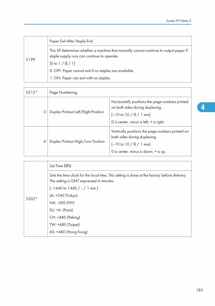
5199
Paper Exit After Staple End
This SP determines whether a machine that normally cannot continue to output paper ifstaple supply runs can continue to operate.
[0 to 1 / 0 / 1]
0: OFF. Paper cannot exit if no staples are available.
1: ON. Paper can exit with no staples.
5212* Page Numbering
3 Duplex Printout Left/Right Position
Horizontally positions the page numbers printedon both sides during duplexing.
[–10 to 10 / 0 / 1 mm]
0 is center, minus is left, + is right.
4 Duplex Printout High/Low Position
Vertically positions the page numbers printed onboth sides during duplexing.
[–10 to 10 / 0 / 1 mm]
0 is center, minus is down, + is up.
5302*
Set Time DFU
Sets the time clock for the local time. This setting is done at the factory before delivery.The setting is GMT expressed in minutes.
[–1440 to 1440 / - / 1 min.]
JA: +540 (Tokyo)
NA: -300 (NY)
EU: +6- (Paris)
CH: +480 (Peking)
TW: +480 (Taipei)
AS: +480 (Hong Kong)
System SP Tables-5
185
4

5307
Summer Time
Lets you set the machine to adjust its date and time automatically with the change toDaylight Savings time in the spring and back to normal time in the fall. This SP lets youset these items:
• Day and time to go forward automatically in April.
• Day and time to go back automatically in October.
• Set the length of time to go forward and back automatically.
The settings for 002 and 003 are done with 8-digit numbers:
Digits Meaning
1st, 2ndMonth. 4: April, 10: October (for months 1 to 9, the first digit of 0 cannotbe input, so the eight-digit setting for 002 or 003 becomes a seven-digitsetting)
3rdThe number of the week for the day selected at the 4th digit. If "0" isselected for "Sunday", for example, and the selected Sunday is the start ofthe 2nd week, then input a "2" for this digit.
4th Day of the week. 0: Sunday, 1: Monday
5th, 6thThe time when the change occurs (24-hour as hex code).
Example: 00:00 (Midnight) = 00, 01:00 (1 a.m.) = 01, and so on.
7th The number of hours to change the time. 1 hour: 1
8thIf the time change is not a whole number (1.5 hours for example), digit 8should be 3 (30 minutes).
1 Setting
Enables/disables the settings for 002 and 003.
[0 to 1 / 1 (NA/EU), 0 (ASIA) / 1 /step]
0: Disable
1: Enable
3Rule Set(Start)
The start of summer time.
4Rule Set(End)
The end of summer time.
4. Appendix: Service Program Mode Tables
186
4

5401*Access Control DFU
This SP stores the settings that limit uses access to SDK application data.
103 Default Document ACL
Used to assign the default access user accessprivileges to their own documents on thedocument server.
[0 to 3 / 0 / 1 step]
0: View, 1: Edit, 2: Edit/Delete,
3: Full control.
104 Authentication Time
Specifies the timeout of the authentication.
[0 to 255 / 0 / 1 sec./step]
0: 60 seconds
1 to 250 seconds
162 Extend Certification Detail
Selects the log out type for the extendauthentication device.
Bit 0: Log-out without an IC card
0: Not allowed (default)
1: Allowed
200 SDK1 Unique ID
"SDK" is the "Software Development Kit". Thisdata can be converted from SAS (VAS) wheninstalled or uninstalled. DFU
201 SDK1 Certification Method
210 SDK2 Unique ID
211 SDK2 Certification Method
220 SDK3 Unique ID
221 SDK3 Certification Method
230 Certification Device
Enables or disables the SDK certification.
• Bit 0: SDK certification
0: Disable (default), 1: Enable
• Bit 1: Not used
• Bit 2: Administrator log in
0: Disable (default), 01: Enable
System SP Tables-5
187
4

240 Detail Option
Enables or disables the log out confirmationoption.
• Bit 0: Log out confirmation option
0: Enable (default), 1: Disable
Selects the automatic log out time.
• Bit 1 and 2: Automatic log out timerreduction
00: 60 seconds (default), 01: 10seconds,10: 20 seconds, 11: 30seconds
5404
User Code Count Clear
Clears the counts for the user codes assigned by the key operator to restrict the use ofthe machine. Press [Execute] to clear.
5411* LDAP Certification
4
Easy Certification
Determines whether easy LDAP certification is done.
[0 or 1 / 1 / 1]
1: On
0: Off
5
Password Null Not Permit
This SP is referenced only when SP5411-4 is set to "1" (On).
[0 or 1 / 0 / 1]
0: Password NULL not permitted.
1: Password NULL permitted.
6
Detail Option
Determines whether LDAP option (anonymous certification) is turned on or off.
[0 to 255 / 0 / 1]
0: OFF
1: ON
5413* Lockout Setting
4. Appendix: Service Program Mode Tables
188
4

1
Lockout On/Off
Switches on/off the lock on the local address book account.
[0 or 1 / 0 / 1]
0: Off
1: On
2
Lockout Threshold
Sets a limit on the frequency of lockouts for account lockouts.
[5 to 10 / 5 / 1]
3
Cancellation On/Off
Determines whether the system waits the prescribed time for input of a correct user IDand password after an account lockout has occurred.
[0 or 1 / 0 / 1]
0: Off (no wait time, lockout not cancelled)
1: On (system waits, cancels lockout if correct user ID and password are entered.
4
Cancellation Time
Determines the length of time that the system waits for correct input of the user ID andpassword after a lockout has occurred. This setting is used only if SP5413-3 is set to"1" (on).
[1 to 9999 / 60 /1 min.]
5414* Access Mitigation
1
Mitigation On/Off
Switches on/off masking of continuously used IDs and passwords that are identical.
[0 or 1 / 0 / 1]
0: Off
1: On
2
Mitigation Time
Sets the length of time for excluding continuous access for identical user IDs andpasswords.
[0 to 60 / 15 / 1 min]
5415* Password Attack
System SP Tables-5
189
4

1
Permissible Number
Sets the number of attempts to attack the system with random passwords to gain illegalaccess to the system.
[0 to 100 / 30 / 1 attempt]
2
Detect Time
Sets the time limit to stop a password attack once such an attack has been detected.
[1 to 10 / 5 / 1 sec.]
5416* Access Information
1
Access User Max Number
Limits the number of users used by the access exclusion and password attack detectionfunctions.
[50 to 200 / 200 / 1 users]
2
Access Password Max Number
Limits the number of passwords used by the access exclusion and password attackdetection functions.
[50 to 200 / 200 /1 passwords]
3
Monitor Interval
Sets the processing time interval for referencing user ID and password information.
[1 to 10 / 3 / 1 sec.]
5417* Access Attack
1
Access Permissible Number
Sets a limit on access attempts when an excessive number of attempts are detected forMFP features.
[0 to 500 / 100 / 1]
2
Attack Detect Time
Sets the length of time for monitoring the frequency of access to MFP features.
[10 to 30 / 10 / 1 sec.]
4. Appendix: Service Program Mode Tables
190
4

3
Productivity Fall Waite
Sets the wait time to slow down the speed of certification when an excessive number ofaccess attempts have been detected.
[0 to 9 / 3 / 1 sec.]
4
Attack Max Number
Sets a limit on the number of requests received for certification in order to slow downthe certification speed when an excessive number of access attempts have beendetected.
[50 to 200 / 200 / 1 attempt]
5420*
User Authentication
These settings should be done with the System Administrator.
Note: These functions are enabled only after the user access feature has beenenabled.
1
Copy
Determines whether certification is required before a user can use the copyapplications.
[0 or 1/ 0 / 1]
0: On
1: Off
11
Document Server
Determines whether certification is required before a user can use the document server.
[0 or 1 / 0 / 1]
0: On
1: Off
21
Fax
Determines whether certification is required before a user can use the fax application.
[0 or 1 / 0 / 1]
0: On
1: Off
System SP Tables-5
191
4

31
Scanner
Determines whether certification is required before a user can use the scanapplications.
[0 or 1 / 0 / 1]
0: On
1: Off
41
Printer
Determines whether certification is required before a user can use the printerapplications.
[0 or 1 / 0 / 1]
0: On
1: Off
51 SDK1[0 or 1 / 0 / 1] 0: ON. 1: OFF
Determines whether certification is required before a user can use theSDK application.
61 SDK2
71 SDK3
5430* Auth Dialog Message Change
1*
Message Change On/Off
Turns on or off the displayed message change for the authentication.
[0 or 1 / 0 / 1]
0: Off, 1: On
2Message Text Download
Executes the message download for the authentication.
3Message Text ID
Inputs message text for the authentication.
5431* External Auth User Preset
10
Tag
Turns on or off the tag copy permission for the external authentication.
[0 or 1 / 1 / -]
0: Not permit, 1: Permit
4. Appendix: Service Program Mode Tables
192
4

11
Entry
Turns on or off the copy permission of the entry information for the externalauthentication.
[0 or 1 / 1 / -]
0: Not permit, 1: Permit
12
Group
Turns on or off the copy permission of the group information for the externalauthentication.
[0 or 1 / 1 / -]
0: Not permit, 1: Permit
20
Turns on or off the copy permission of the mail information for the externalauthentication.
[0 or 1 / 1 / -]
0: Not permit, 1: Permit
30
Fax
[0 or 1 / 1 / -]
0: Not permit, 1: Permit
Turns on or off the copy permission of the fax information for the externalauthentication.
31
FaxSub
Turns on or off the copy permission of the fax additional information for the externalauthentication.
[0 or 1 / 1 / -]
0: Not permit, 1: Permit
32
Folder
Turns on or off the copy permission of the folder information for the externalauthentication.
[0 or 1 / 1 / -]
0: Not permit, 1: Permit
System SP Tables-5
193
4

33
ProtectCode
Turns on or off the copy permission of the protection code information for the externalauthentication.
[0 or 1 / 1 / -]
0: Not permit, 1: Permit
34
SmtpAuth
Turns on or off the copy permission of the SMTP information for the externalauthentication.
[0 or 1 / 1 / -]
0: Not permit, 1: Permit
35
LdapAuth
Turns on or off the copy permission of the LDAP information for the externalauthentication.
[0 or 1 / 1 / -]
0: Not permit, 1: Permit
36
Smb Ftp Fldr Auth
Turns on or off the copy permission of the SMB/FTP information for the externalauthentication.
[0 or 1 / 1 / -]
0: Not permit, 1: Permit
37
AcntAcl
Turns on or off the copy permission of the account ACL information for the externalauthentication.
[0 or 1 / 1 / -]
0: Not permit, 1: Permit
38
DocumentAcl
Turns on or off the copy permission of the document ACL information for the externalauthentication.
[0 or 1 / 1 / -]
0: Not permit, 1: Permit
4. Appendix: Service Program Mode Tables
194
4

40
CertCrypt
Turns on or off the copy permission of the authentication information for the externalauthentication.
[0 or 1 / 1 / -]
0: Not permit, 1: Permit
50
UserLimitCount
Turns on or off the copy permission of the maximum number information for theexternal authentication.
[0 or 1 / 1 / -]
0: Not permit, 1: Permit
5481*Authentication Error Code
These SP codes determine how the authentication failures are displayed.
1
System Log Disp
Determines whether an error code appears in the system log after a user authenticationfailure occurs.
[0 or 1 / 0 / -]
0: Off
1: On
2
Panel Disp
Determines whether an error code appears on the operation panel after a userauthentication failure occurs.
[0 or 1 / 1 / 1]
1: On
0: Off
5490*
MF Keycard Japan Only
Sets up operation of the machine with a keycard.
[0 or 1 / 0 / 1]
0: Disabled. Cancels operation if no code is input.
1: Enabled. Allows operation if another code is input and decrements the counter oncefor use of the entered code.
System SP Tables-5
195
4

5491*
Optional Counter
Determines whether to cancel the job when MK1 keycard is pulled out from themachine during job.
[0 to 11111111 / 0 / 1]
0: On. Cancels the job.
1: Off. Allows operation if MK1 keycard is pulled out from the machine during the job.
5501* PM Alarm
1
PM Alarm Level
[0 to 9999 / 0 / 1 / step]
0: Alarm off
1 to 9999: Alarm goes off when Value (1 to 9999) x 1000 > PM counter
2
Original Count Alarm
[0 or 1 / 1 / -]
0: No alarm sounds
1: Alarm sounds after the number of originals passing through the ARDF > 10,000
5504*
Jam Alarm
Sets the alarm to sound for the specified jam level (document misfeeds are notincluded).
[0 to 3 / 3 / 1 step]
0: Zero (Off)
1: Low (2.5K jams)
2: Medium (3K jams)
3: High (6K jams)
5505*
Error Alarm
Sets the error alarm level.
[0 to 255 / 20 (D120/D139), 25 (D121/D140), 35 (D122/D141) / 100copies / step]
5507* Supply Alarm
4. Appendix: Service Program Mode Tables
196
4
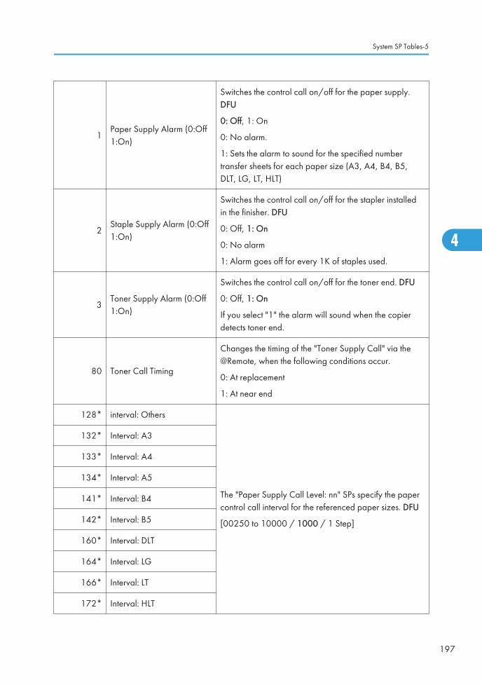
1Paper Supply Alarm (0:Off1:On)
Switches the control call on/off for the paper supply.DFU
0: Off, 1: On
0: No alarm.
1: Sets the alarm to sound for the specified numbertransfer sheets for each paper size (A3, A4, B4, B5,DLT, LG, LT, HLT)
2Staple Supply Alarm (0:Off1:On)
Switches the control call on/off for the stapler installedin the finisher. DFU
0: Off, 1: On
0: No alarm
1: Alarm goes off for every 1K of staples used.
3Toner Supply Alarm (0:Off1:On)
Switches the control call on/off for the toner end. DFU
0: Off, 1: On
If you select "1" the alarm will sound when the copierdetects toner end.
80 Toner Call Timing
Changes the timing of the "Toner Supply Call" via the@Remote, when the following conditions occur.
0: At replacement
1: At near end
128* interval: Others
The "Paper Supply Call Level: nn" SPs specify the papercontrol call interval for the referenced paper sizes. DFU
[00250 to 10000 / 1000 / 1 Step]
132* Interval: A3
133* Interval: A4
134* Interval: A5
141* Interval: B4
142* Interval: B5
160* Interval: DLT
164* Interval: LG
166* Interval: LT
172* Interval: HLT
System SP Tables-5
197
4

5508* CC Call
1 Jam Remains Enables/disables initiating a call.
[0 or 1 / 1 / 1]
0: Disable
1: Enable
2 Continuous Jams
3 Continuous Door Open
11Jam Detection: TimeLength
Sets the length of time to determine the length of anunattended paper jam.
[3 to 30 / 10 / 1 minute]
12Jam Detection:Continuous Count
Sets the number of continuous paper jams required to initiatea call.
[2 to 10 / 5 / 1 time]
13 Door Open: Time Length
Sets the length of time the remains opens to determine whento initiate a call.
[3 to 30 / 10 / 1 minute]
5515*
SC/Alarm Setting
With NRS (New Remote Service) in use, these SP codes can be set to issue an SC callwhen an SC error occurs. If this SP is switched off, the SC call is not issued when an SCerror occurs.
1 SC Call
[0 or 1 / 1 / - ]
0: Off
1: On
2 Service Parts Near End Call
3 Service Parts End Call
4 User Call
6 Communication Test Call
[0 or 1 / 1 / - ]
0: Off
1: On
7 Machine Information Notice
8 Alarm Notice
10 Supply Automatic Ordering Call
11 Supply Management Report Call
12 Jam/Door Open Call
4. Appendix: Service Program Mode Tables
198
4

5801
Memory Clear
Resets NVRAM data to the default settings. Before executing any of these SP codes,print an SMC Report.
1 All Clear Initializes items 2 to 15 below.
2 EngineInitializes all registration settings for the engineand copy process settings.
3 SCSInitializes default system settings, SCS (SystemControl Service) settings, operation displaycoordinates, and ROM update information.
4 IMH Memory ClearInitializes the image file system.
(IMH: Image Memory Handler)
5 MCS
Initializes the automatic delete time setting forstored documents.
(MCS: Memory Control Service)
6 Copier application Initializes all copier application settings.
7 Fax applicationInitializes the fax reset time, job login ID, allTX/RX settings, local storage file numbers, andoff-hook timer.
8 Printer applicationInitializes the printer defaults, programsregistered, the printer SP bit switches, and theprinter CSS counter.
9 Scanner applicationInitializes the defaults for the scanner and all thescanner SP modes.
10 Web Service
Deletes the Netfile (NFA) management files andthumbnails, and initializes the Job login ID.
Netfiles: Jobs to be printed from the documentserver using a PC and the DeskTopBindersoftware
11 NCS
Initializes the system defaults and interfacesettings (IP addresses also), the SmartNetMonitorfor Admin settings, WebStatusMonitor settings,and the TELNET settings.
(NCS: Network Control Service)
System SP Tables-5
199
4

12 R-FAXInitializes the job login ID, SmartNetMonitor forAdmin, job history, and local storage filenumbers.
14 Clear DCS SettingInitializes the DCS (Delivery Control Service)settings.
15 Clear UCS SettingInitializes the UCS (User Information ControlService) settings.
16 MIRS SettingInitializes the MIRS (Machine Information ReportService) settings.
17 CCSInitializes the CCS (Certification and Charge-control Service) settings.
18 SRM Memory ClearInitializes the SRM (System Resource Manager)settings.
19 LCS Initializes the LCS (Log Count Service) settings.
20 Web Uapli Initializes Web application settings.
21 ECS Initializes ECS (Engine Control Service).
5803
Input Check
Displays signals received from sensors and switches.
Press the (Clear Modes) key to exit
1 Tray 1: Paper Size Sensor
2 Tray 2: Paper Size Sensor
3 Tray 1: Tray Set Sensor
4 Tray 2: Tray Set Sensor
5 Tray 1: Paper Height Sensor 1
6 Tray 1: Paper Height Sensor 2
7 Tray 2: Paper Height Sensor 1
8 Tray 2: Paper Height Sensor 2
9 Tray 1: Paper End Sensor
4. Appendix: Service Program Mode Tables
200
4

10 Tray 2: Paper End Sensor
11 Tray 1: Paper Lift Sensor
12 Tray 2: Paper Lift Sensor
13 1st Paper Leading Edge Sensor
14 2nd Paper Leading Edge Sensor
15 By-pass: Paper Size Sensor
16 By-pass: Paper End Sensor
17 By-pass: Paper Length Sensor
18 By-pass: Home Position Sensor
19 Paper Exit Sensor
20 Paper Feed Sensor 1
21 Paper Feed Sensor 2
22 Registration Sensor
23 Interchange Sensor
24 Duplex: Exit Sensor
25 Duplex: Entrance Sensor
26 Paper Overflow Sensor
27 Front Safety Sw - 24V
28 Front Safety Sw - 5V
29 Right Cover Open
30 Duplex Fan Lock
31 CTL Fan Lock
33 Fan Lock
34 Bottle Motor Lock
35 Main Motor Lock
36 Interchange Unit Set
System SP Tables-5
201
4

37 PCU Set
38 Fusing Unit Set
39 Key Card Set
40 Mechanical Counter Set
41 Key Counter Set
42 BCU Version
87 BANK_VFEEDSNS1
88 BANK_VFEEDSNS2
89 BANK_FEEDSNS1
90 BANK_FEEDSNS2
91 BANK_VFEEDCOVER
200 Scanner HP Sensor
201 Platen Cover Sensor
5804Output Check
Turns on electrical components individually for test purposes.
1 Main Motor: CW: High
2 Main Motor: CW: Low
3 Main Motor: CCW: High
4 Main Motor: CCW: Low
5 Duplex Motor: CCW: 425.3
6 Duplex Motor: CCW: 345
7 Duplex Motor: CCW: 153
8 Duplex Motor: CCW: 123.8
9 Interchange Motor: CW: 424
10 Interchange Motor: CW: 345.1
4. Appendix: Service Program Mode Tables
202
4

11 Interchange Motor: CW: 152
12 Interchange Motor: CW: 123.8
13 Interchange Motor: CCW: 424
14 Interchange Motor: CCW: 345.1
15 Interchange Motor: CCW: 152
16 Interchange Motor: CCW: 123.8
17 By-pass Feed Motor: CW: High
18 By-pass Feed Motor: CW: Low
19 By-pass Feed Motor: CCW
20 Toner Bottle Motor
21 1st Tray Up
22 1st Tray Down
23 2nd Tray Up
24 2nd Tray Down
25 Exhaust Fan Motor: High
26 Exhaust Fan Motor: Low
27 Duplex Fan
28 CTL Fan
29 PSU Fan
32 Registration CL
33 1st Paper Feed CL
34 2nd Paper Feed CL
35 Paper Transport CL1
36 Paper Transport CL2
37 Pick Up SOL1
38 Pick Up SOL2
System SP Tables-5
203
4
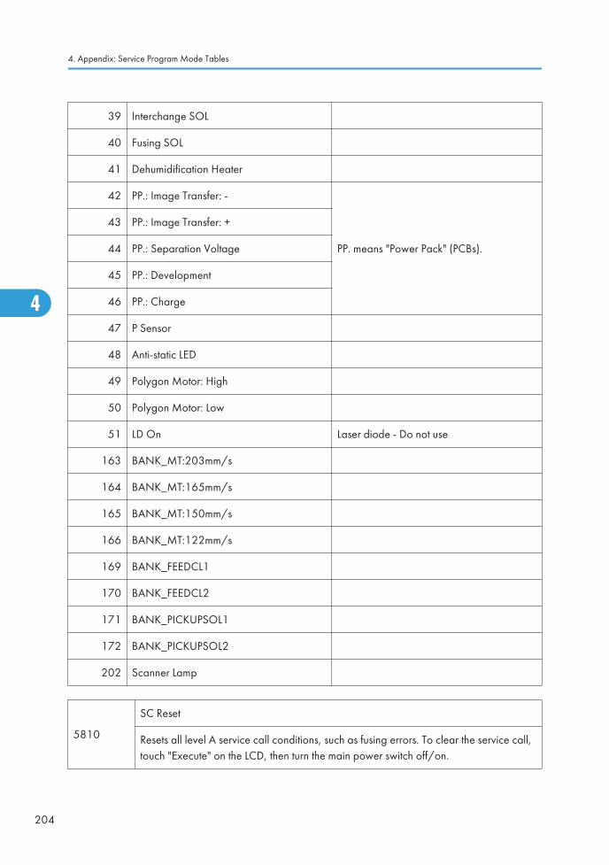
39 Interchange SOL
40 Fusing SOL
41 Dehumidification Heater
42 PP.: Image Transfer: -
PP. means "Power Pack" (PCBs).
43 PP.: Image Transfer: +
44 PP.: Separation Voltage
45 PP.: Development
46 PP.: Charge
47 P Sensor
48 Anti-static LED
49 Polygon Motor: High
50 Polygon Motor: Low
51 LD On Laser diode - Do not use
163 BANK_MT:203mm/s
164 BANK_MT:165mm/s
165 BANK_MT:150mm/s
166 BANK_MT:122mm/s
169 BANK_FEEDCL1
170 BANK_FEEDCL2
171 BANK_PICKUPSOL1
172 BANK_PICKUPSOL2
202 Scanner Lamp
5810
SC Reset
Resets all level A service call conditions, such as fusing errors. To clear the service call,touch "Execute" on the LCD, then turn the main power switch off/on.
4. Appendix: Service Program Mode Tables
204
4

5811 Machine Serial DFU
2Display
Displays the machine serial number.
4BICU
Inputs the serial number.
5812* Service Tel. No. Setting
1 ServiceInputs the telephone number of the CE (displayed when a servicecall condition occurs.)
2 FacsimileUse this to input the fax number of the CE printed on the CounterReport (UP mode). Not Used
3 Supply Displayed on the initial SP screen.
4 OperationAllows the service center contact telephone number to be displayedon the initial screen.
5816* Remote Service
1*
I/F Setting
Selects the remote service setting.
[0 to 2 / 2 / - /step]
0: Remote service off
1: DFU
2: @Remote service on
2*
CE Call
Performs the CE Call at the start or end of the service.
[0 or 1 / 1 / 1 /step]
0: Start of the service
1: End of the service
NOTE: This SP is activated only when SP 5816-001 is set to "1".
System SP Tables-5
205
4

3*
Function Flag
Enables or disables the remote service function.
[0 to 1 / 0 / 1 /step]
0: Disabled, 1: Enabled
NOTE: This SP setting is changed to "1" after @Remote register has been completed.
7*
SSL Disable
Uses or does not use the RCG certification by SSL when calling the RCG.
[0 to 1 / 0 / 1 /step]
0: Uses the RCG certification
1: Does no use the RCG certification
8*
RCG Connect Timeout
Specifies the connect timeout interval when calling the RCG.
[1 to 90 / 30 / 1 second /step]
9*
RCG Write Timeout
Specifies the write timeout interval when calling the RCG.
[0 to 100 / 60 / 1 second /step]
10*
RCG Read Timeout
Specifies the read timeout interval when calling the RCG.
[0 to 100 / 60 / 1 second /step]
11*
Port 80 Enable
Enables/disables access via port 80 to the SOAP method.
[0 or 1 / 0 / – ]
0: Disabled, 1: Enabled
13*
RFU (Remote Firmware Update) Timing
Selects the RFU timing.
[0 or 1 / 1 / – ]
0: RFU is executed whenever update request is received.
1: RFU is executed only when the machine is in the sleep mode.
4. Appendix: Service Program Mode Tables
206
4

21*
RCG – C Registed DFU
This SP displays the Embedded RC Gate installation end flag.
0: Installation not completed
1: Installation completed
23*
Connect Type (N/M)
This SP displays and selects the Embedded RC Gate connection method.
0: Internet connection
1: Dial-up connection
61*Cert. Expire Timing DFU
Proximity of the expiration of the certification.
62*
Use Proxy DFU
This SP setting determines if the proxy server is used when the machine communicateswith the service center.
0: proxy server is used
1: proxy server is not used
63*
Proxy Host
This SP sets the address of the proxy server used for communication betweenEmbedded RC Gate-N and the gateway. Use this SP to set up or display the customerproxy server address. The address is necessary to set up Embedded RC Gate-N.
• The address display is limited to 128 characters. Characters beyond the 128character are ignored.
• This address is customer information and is not printed in the SMC report.
64*
Proxy Port Number
This SP sets the port number of the proxy server used for communication betweenEmbedded RC Gate-N and the gateway. This setting is necessary to set up EmbeddedRC Gate-N.
• This port number is customer information and is not printed in the SMC report.
System SP Tables-5
207
4

65*
Proxy User Name
This SP sets the HTTP proxy certification user name.
• The length of the name is limited to 31 characters. Any character beyond the 31stcharacter is ignored.
• This name is customer information and is not printed in the SMC report.
66*
Proxy Password
This SP sets the HTTP proxy certification password.
• The length of the name is limited to 31 characters. Any character beyond the 31stcharacter is ignored.
• This name is customer information and is not printed in the SMC report.
67* CERT: Up State
4. Appendix: Service Program Mode Tables
208
4

Displays the status of the certification update.
0 The certification used by Embedded RC Gate is set correctly.
1The certification request (setAuthKey) for update has been received from the GWURL and certification is presently being updated.
2The certification update is completed and the GW URL is being notified of thesuccessful update.
3The certification update failed, and the GW URL is being notified of the failedupdate.
4The period of the certification has expired and new request for an update is beingsent to the GW URL.
11
A rescue update for certification has been issued and a rescue certification settingis in progress for the rescue GW connection.
12
The rescue certification setting is completed and the GW URL is being notified ofthe certification update request.
13
The notification of the request for certification update has completed successfully,and the system is waiting for the certification update request from the rescue GWURL.
14
The notification of the certification request has been received from the rescue GWcontroller, and the certification is being stored.
15
The certification has been stored, and the GW URL is being notified of thesuccessful completion of this event.
16
The storing of the certification has failed, and the GW URL is being notified of thefailure of this event.
17
The certification update request has been received from the GW URL, the GWURL was notified of the results of the update after it was completed, but acertification error has been received, and the rescue certification is beingrecorded.
18
The rescue certification of No. 17 has been recorded, and the GW URL is beingnotified of the failure of the certification update.
System SP Tables-5
209
4

68*
CERT: Error
Displays a number code that describes the reason for the request for update of thecertification.
0 Normal. There is no request for certification update in progress.
1 Request for certification update in progress. The current certification has expired.
2An SSL error notification has been issued. Issued after the certification hasexpired.
3 Notification of shift from a common authentication to an individual certification.
4 Notification of a common certification without ID2.
5 Notification that no certification was issued.
6 Notification that GW URL does not exist.
69* CERT: Up ID The ID of the request for certification.
83* Firmware Up Status Displays the status of the firmware update.
85* Firm Up User Check
This SP setting determines if the operator can confirm theprevious version of the firmware before the firmwareupdate execution. If the option to confirm the previousversion is selected, a notification is sent to the systemmanager and the firmware update is done with thefirmware files from the URL.
86* Firmware SizeAllows the service technician to confirm the size of thefirmware data files during the firmware updateexecution.
87 CERT: Macro Ver. Displays the macro version of the @Remote certification.
88 CERT: PAC Ver. Displays the PAC version of the @Remote certification.
89 CERT: ID2 Code
Displays ID2 for the @Remote certification. Spaces aredisplayed as underscores (_). Asterisks (*) indicate thatno @Remote certification exists."000000___________" indicates "Commoncertification".
4. Appendix: Service Program Mode Tables
210
4

90 CERT: Subject
Displays the common name of the @Remote certificationsubject. CN = the following 17 bytes. Spaces aredisplayed as underscores (_). Asterisks (*) indicate thatno @Remote certification exists."000000___________" indicates "Commoncertification".
91 CERT: Serial No.Displays serial number for the @Remote certification.Asterisks (*) indicate that no @Remote certificationexists.
92 CERT: IssuerDisplays the common name of the issuer of the @Remotecertification. CN = the following 30 bytes. Asterisks ()indicate that no @Remote certification exists.
93 CERT: Valid StartDisplays the start time of the period for which the current@Remote certification is enabled.
94 CERT: Valid EndDisplays the end time of the period for which the current@Remote certification is enabled.
150*Selection Country
Not used
151Line Type Automatic Judgment
Not used
152Line Type Judgment Result
Not used
153*Selection Dial/Push
Not used
154*Outside Line/Outgoing Number
Not used
156*Dial Up User Name
Not used
157*Dial Up Password
Not used
System SP Tables-5
211
4

161*Local Phone Number
Not used
162*Connection Timing Adjustment: Incoming
Not used
163*Access Point
Not used
164*Line Connecting
Not used
173*Modem Serial Number
Not used
174Retransmission Limit
Not used
187*FAX TX Priority
Not used
200Manual Polling
Not used
201
Regist: Status
Displays a number that indicates the status of the @Remote service device.
0: Neither the @Remote device nor Embedded RCG Gate is set.
1: The Embedded RCG Gate is being set. Only Box registration is completed. In thisstatus, @Remote device cannot communicate with this device.
2: The Embedded RCG Gate is set. In this status, the @Remote device cannotcommunicate with this device.
3: The @Remote device is being set. In this status the Embedded RCG Gate cannot beset.
4: The @Remote module has not started.
202*Letter Number
Allows entry of the request number needed for the Embedded RCG Gate.
4. Appendix: Service Program Mode Tables
212
4

203Confirm Execute
Executes the confirmation request to the @Remote Gateway.
204
Confirm Result
Displays a number that indicates the result of the confirmation executed withSP5816-203.
0: Succeeded
1: Confirmation number error
3: Proxy error (proxy enabled)
4: Proxy error (proxy disabled)
5: Proxy error (Illegal user name or password)
6: Communication error
8: Other error
9: Confirmation executing
205
Confirm Place
Displays the result of the notification sent to the device from the Gateway in answer tothe confirmation request. Displayed only when the result is registered at the Gateway.
206Register Execute
Executes "Embedded RCG Registration".
207
Register Result
Displays a number that indicates the registration result.
0: Succeeded
1: Confirmation number error
2: Registration in progress
3: Proxy error (proxy enabled)
4: Proxy error (proxy disabled)
5: Proxy error (Illegal user name or password)
6: Communication error
8: Other error
9: Registration executing
System SP Tables-5
213
4

208
Error Code
Displays a number that describes the error code that was issued when eitherSP5816-204 or SP5816-207 was executed.
Cause Code Meaning
Illegal Modem Parameter
-11001 Chat parameter error
-11002 Chat execution error
-11003 Unexpected error
Operation Error,Incorrect Setting
-12002Inquiry, registration attempted withoutacquiring device status.
-12003Attempted registration without execution of aninquiry and no previous registration.
-12004Attempted setting with illegal entries forcertification and ID2.
-12005@Remote communication is prohibited. Thedevice has an Embedded RC gate-relatedproblem.
-12006A confirmation request was made after theconfirmation had been already completed.
-12007The request number used at registration wasdifferent from the one used at confirmation.
-12008Update certification failed because mainframewas in use.
-12009ID2 between NVRAM and self-signedcertificate is different.
-12010 Certificate area is not initialized.
4. Appendix: Service Program Mode Tables
214
4

Error Caused byResponse from GW URL
-2385Attempted dial up overseas without the correctinternational prefix for the telephone number.
-2387 Not supported at the Service Center
-2389 Database out of service
-2390 Program out of service
-2391 Two registrations for same device
-2392 Parameter error
-2393 RCG device not managed
-2394 Device not managed
-2395 Box ID for RCG device is illegal
-2396 Device ID for RCG device is illegal
-2397 Incorrect ID2 format
-2398 Incorrect request number format
209 Instl Clear
Releases the machine from its Embedded RCG Gate setup.
NOTE: Turn off and on the main power switch after thissetting has been changed.
250 CommLog Print Prints the communication log.
5821* Remote Service Address Japan Only
2 RCG IP Address
Sets the IP address of the RCG (Remote CommunicationGate) destination for call processing at the remote servicecenter.
[00000000htoFFFFFFFFh/1]
5824
NVRAM Data Upload
Uploads the NVRAM data to an SD card. Push Execute.
Note: When uploading data in this SP mode, the front door must be open.
System SP Tables-5
215
4

5825
NVRAM Data Download
Downloads data from an SD card to the NVRAM in the machine. After downloading iscompleted, remove the card and turn the machine power off and on.
5828* Network Setting
50*
1284 Compatibility (Centro)
Enables and disables bi-directional communication on the parallel connection betweenthe machine and a computer.
[0 or 1 / 1 / 1 ]
0:Off
1: On
52*
ECP (Centro)
Disables and enables the ECP feature (1284 Mode) for data transfer.
[0 or 1 / 1 / 1 ]
0: Disabled
1: Enabled
65*
Job Spooling
Switches job spooling on and off.
[0 or 1 / 0 / 1 ]
0: No spooling, 1: Spooling enabled
66*
Job Spool Clear: Start Time
This SP determines whether the job interrupted at power off is resumed at the next poweron. This SP operates only when SP5828 065 is set to 1.
[0 or 1 / 1 / 1 ]
1: Resumes printing spooled jog.
0: Clears spooled job.
4. Appendix: Service Program Mode Tables
216
4

69*
Job Spooling (Protocol)
This SP determines whether job spooling is enabled or disabled for each protocol. This isa 8-bit setting.
[0 or 1 / 1 / 1 ]
0: No spooling, 1: Spooling enabled
0 LPR 4 BMLinks (Japan Only)
1 FTP (Not Used) 5 DIPRINT
2 IPP 6 Reserved (Not Used)
3 SMB 7 Reserved (Not Used)
90*
TELNET (0:OFF 1:ON)
Disables or enables Telnet operation. If this SP is disabled, the Telnet port is closed.
[0 or 1 / 1 / 1 ]
0: Disable
1: Enable
91*
Web (0:OFF 1:ON)
Disables or enables the Web operation.
[0 or 1 / 1 / 1 ]
0: Disable
1: Enable
145
Active IPv6 Link Local Address
This is the IPv6 local address referenced on the Ethernet or wireless LAN (802.11) in theformat:
"Link-Local address" + "Prefix Length"
The IPv6 address consists of a total 128 bits configured in 8 blocks of 16 bits each.These notations can be abbreviated. See "Note: IPV6 Addresses " below this table.
System SP Tables-5
217
4

147Active IPv6 StatusAddress 1
These SPs are the IPv6 stateless addresses (1 to 5) referenced onthe Ethernet or wireless LAN (802.11) in the format:
"Stateless Address" + "Prefix Length"
The IPv6 address consists of a total 128 bits configured in 8blocks of 16 bits each.
149Active IPv6 StatusAddress 2
151Active IPv6 StatusAddress 3
153Active IPv6 StatusAddress 3
155Active IPv6 StatusAddress 4
156*
IPv6 Manual Address
This SP is the IPv6 manually set address referenced on the Ethernet or wireless LAN(802.11) in the format:
"Manual Set Address" + "Prefix Length"
The IPv6 address consists of a total 128 bits configured in 8 blocks of 16 bits each.These notations can be abbreviated. See "Note: IPV6 Addresses" below this table.
158*
IPv6 Gateway Address
This SP is the IPv6 gateway address referenced on the Ethernet or wireless LAN(802.11). The IPv6 address consists of a total 128 bits configured in 8 blocks of 16 bitseach. These notations can be abbreviated. See "Note: IPV6 Addresses " below thistable.
Note: IPV6 Addresses
Ethernet and the Wireless LAN (802.11) reference the IPV6 "Link-Local address + Prefix Length". TheIPV6 address consists of 128 bits divided into 8 blocks of 16 bits:
aaaa:bbbb:cccc:dddd:eeee:ffff:gggg:hhhh:
The prefix length is inserted at the 17th byte (Prefix Range: 0x0~0x80). The initial setting is 0x40(64).
For example, the data:
2001123456789012abcdef012345678940h
is expressed:
2001:1234:5678:9012:abcd:ef01:2345:6789: prefixlen 64
However, the actual IPV6 address display is abbreviated according to the following rules.
Rules for Abbreviating IPV6 Addresses
1. The IPV6 address is expressed in hexadecimal delimited by colons (:) with the following characters:
4. Appendix: Service Program Mode Tables
218
4

0123456789abcdefABCDEF
2. A colon is inserted as a delimiter every 4th hexadecimal character.
fe80:0000:0000:0000:0207:40ff:0000:340e
3. The notations can be abbreviated by eliminating zeros where the MSB and digits following theMSB are zero. The example in "2" above, then, becomes:
fe80:0:0:0207:40ff:0:340e
4. Sections where only zeros exist can be abbreviated with double colons (::). This abbreviation canbe done also where succeeding sections contain only zeros (but this can be done only at one pointin the address). The example in "2" and "3" above then becomes:
fe80::207:40ff:0:340e (only the first null sets zero digits are abbreviated as "::")
-or-
fe80:0:0:0:207:40ff::340e (only the last null set before "340e" is abbreviated as "::")
161*
IPv6 Stateless Auto Setting
Enables/disables the stateless automatic setting for Ethernet/wireless LAN operation.
[0 or 1 / 1 / 1]
1: Enable
0: Disable
236*
Web Item Invisible
Determines whether each item can be set in Websys.
[0x0000 to 0xffff/0xffff]
0: Not displayed, 1: Displayed
Bit 0: NetRICOH
Bit 1: Vendor for consumables
Bit 2-15: Reserved
237*
Web Shopping Link Invisible
Determines whether the NetRICOH link is displayed on the Websys top page and linkpage.
[0 or 1 / 1 / 1]
1: Display
0: No display
System SP Tables-5
219
4

238*
Web Supplies Link Invisible
Determines whether the consumable vendor link is displayed on the Websys top pageand link page.
[0 or 1 / 1 / 1]
1: Display
0: No display
239*
Web Link 1 Name
Determines whether an name entered for "URL1" is displayed on the Websys link page.The name length is limited to 31 characters.
240*
Web Link 1 URL
Sets the URL referenced for URL1 linked to the Websys linked page. The link name islimited to 127 characters.
241*
Web Link 1 Visible
Determines whether the link for URL1 is displayed on the Websys top page.
[0 or 1 / 1 / 1]
1: Display
0: No display
242*
Web Link 2 Name
Determines whether a name entered for "URL2" is displayed on the Websys link page.The name length is limited to 31 characters.
243*
Web Link 2 URL
Sets the URL referenced for URL2 linked to the Websys linked page. The link name islimited to 127 characters.
244*
Web Link 2 Visible
Determines whether the link for URL2 is displayed on the Websys top page.
[0 or 1 / 1 / 1]
1: Display
0: No display
5831InitialSettingClear
Execute to clears the initial setting mode.
4. Appendix: Service Program Mode Tables
220
4

5832
HDD Formatting
Enter the SP number for the partition to initialize, then press #. When the execution ends,cycle the machine off and on.
1 HDD Formatting (All)
2 HDD Formatting (IMH)
3 HDD Formatting (Thumbnail)
4 HDD Formatting (Job Log)
5 HDD Formatting (Printer Fonts)
6 HDD Formatting (User Info)
7 Mail RX Data
8 Mail TX Data
9 HDD Formatting (Data for Design)
10 HDD Formatting (Log)
11 HDD Formatting (Ridoc I/F) (for Ridoc Desk Top Binder)
5836* Capture Setting
1
Capture Function (0:Off 1:On)
With this function disabled, the settings related to the capture feature cannot beinitialized, displayed, or selected.
[0 to 1 / 0 / 1]
0: Disable
1: Enable
2
Panel Setting
Determines whether each capture related setting can be selected or updated from theinitial system screen.
[0 to 1 / 0 / 1]
0: Enable
1: Disable
The setting for SP5836-001 has priority.
System SP Tables-5
221
4

72Reduction for Copy B&WText
[0 to 6 / 0 / 1]
0:1, 1:1/2, 2:1/3, 3:1/4, 6:2/3
73Reduction for Copy B&WOther
[0 to 6 / 0 / 1]
0:1, 1:1/2, 2:1/3, 3:1/4, 6:2/3
75 Reduction for Printer B&W[0 to 6 / 0 / 1]
0 1, 1:1/2, 2:1/3, 3:1/4, 6:2/3
78Reduction for Printer B&W1200dpi
[1 to 5 / 1 / 1]
1:1/2, 3:1/4, 4:1/6, 5:1/8
82Format for Copy B&WText
[0 to 3 / 1 / 1]
0: JFIF/JPEG, 1: TIFF/MMR, 2: TIFF/MH, 3: TIFF/MR
83 Format Copy B&W Other[0 to 3 / 1 / 1]
0: JFIF/JPEG, 1: TIFF/MMR, 2: TIFF/MH, 3: TIFF/MR
85 Format for Printer B&W[0 to 3 / 1 / 1]
0: JFIF/JPEG, 1: TIFF/MMR, 2: TIFF/MH, 3: TIFF/MR
91
Default for JPEG [5 to 95 / 50 / 1]
Sets the JPEG format default for documents sent to the document management serverwith the MLB, with JPEG selected as the format. Enabled only when optional File FormatConverter (MLB: Media Link Board) is installed.
101 Primary srv IP addressSets the IP address for the primary capture server. This isbasically adjusted by the remote system.
102 Primary srv scheme This is basically adjusted by the remote system.
103 Primary srv port number This is basically adjusted by the remote system.
104 Primary srv URL pathSets the IP address for the primary capture server. This isbasically adjusted by the remote system.
111 Secondary srv IP address This is basically adjusted by the remote system.
112 Secondary srv scheme This is basically adjusted by the remote system.
113Secondary srv portnumber
This is basically adjusted by the remote system.
114 Secondary srv URL path This is basically adjusted by the remote system.
4. Appendix: Service Program Mode Tables
222
4

120 Default Reso Rate Switch This is basically adjusted by the remote system.
122
Reso: Copy (Mono) [0 to 255 / 3 / 1/step]
Selects the resolution for BW copy mode. This is basically adjusted by the remote system.
0: 600dpi/ 1: 400dpi/ 2: 300dpi/ 3: 200dpi/ 4: 150dpi/ 5: 100dpi/ 6: 75dpi
124
Reso: Print (Mono) [0 to 255 / 3 / 1/step]
Selects the resolution for BW print mode. This is basically adjusted by the remote system.
0: 600dpi/ 1: 400dpi/ 2: 300dpi/ 3: 200dpi/ 4: 150dpi/ 5: 100dpi/ 6: 75dpi
126
Reso: Fax (Mono) [0 to 255 / 3 / 1/step]
Selects the resolution for BW fax mode. This is basically adjusted by the remote system.
0: 600dpi/ 1: 400dpi/ 2: 300dpi/ 3: 200dpi/ 4: 150dpi/ 5: 100dpi/ 6: 75dpi
127
Reso: Scan (Color) [0 to 255 / 4 / 1/step]
Selects the resolution for color scanning mode. This is basically adjusted by the remotesystem.
0: 600dpi/ 1: 400dpi/ 2: 300dpi/ 3: 200dpi/ 4: 150dpi/ 5: 100dpi/ 6: 75dpi
128
Reso: Scan (Mono) [0 to 255 / 3 / 1/step]
Selects the resolution for BW scanning mode. This is basically adjusted by the remotesystem.
0: 600dpi/ 1: 400dpi/ 2: 300dpi/ 3: 200dpi/ 4: 150dpi/ 5: 100dpi/ 6: 75dpi
141All Addr Info Switch
[0 or 1 / 1 / -]
0: Off, 1: On
Turns on or off the all address information transmission for the captured resources.
142
Stand-by Doc MaxNumber
[10 to 9999 / 2000 / 1/step]
Selects the maximum number of captured documents to be transmitted to the documentserver.
5840* IEEE 802.11
System SP Tables-5
223
4
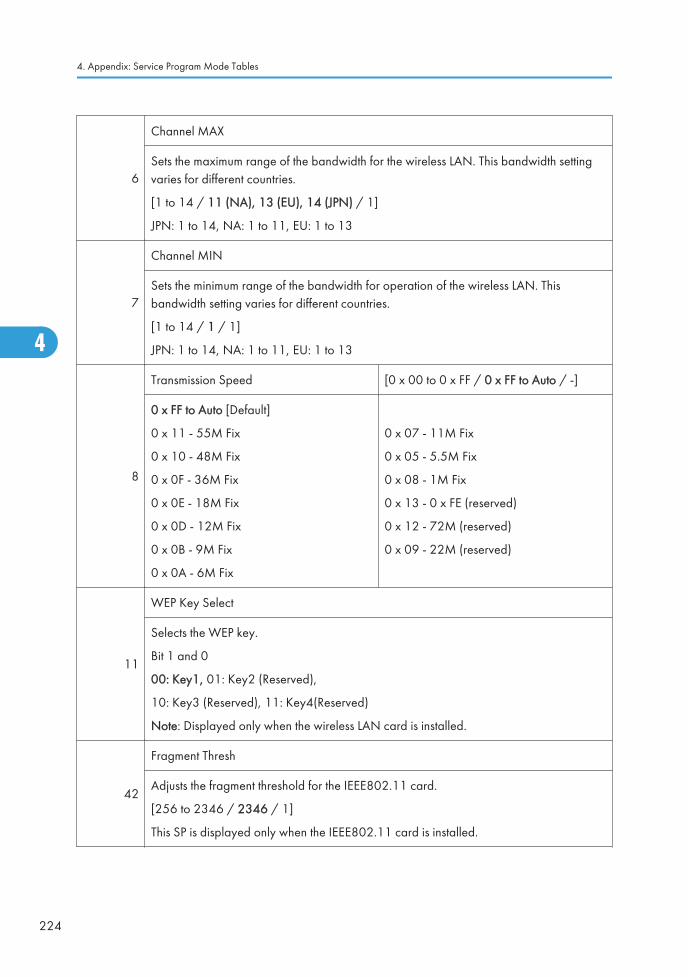
6
Channel MAX
Sets the maximum range of the bandwidth for the wireless LAN. This bandwidth settingvaries for different countries.
[1 to 14 / 11 (NA), 13 (EU), 14 (JPN) / 1]
JPN: 1 to 14, NA: 1 to 11, EU: 1 to 13
7
Channel MIN
Sets the minimum range of the bandwidth for operation of the wireless LAN. Thisbandwidth setting varies for different countries.
[1 to 14 / 1 / 1]
JPN: 1 to 14, NA: 1 to 11, EU: 1 to 13
8
Transmission Speed [0 x 00 to 0 x FF / 0 x FF to Auto / -]
0 x FF to Auto [Default]
0 x 11 - 55M Fix
0 x 10 - 48M Fix
0 x 0F - 36M Fix
0 x 0E - 18M Fix
0 x 0D - 12M Fix
0 x 0B - 9M Fix
0 x 0A - 6M Fix
0 x 07 - 11M Fix
0 x 05 - 5.5M Fix
0 x 08 - 1M Fix
0 x 13 - 0 x FE (reserved)
0 x 12 - 72M (reserved)
0 x 09 - 22M (reserved)
11
WEP Key Select
Selects the WEP key.
Bit 1 and 0
00: Key1, 01: Key2 (Reserved),
10: Key3 (Reserved), 11: Key4(Reserved)
Note: Displayed only when the wireless LAN card is installed.
42
Fragment Thresh
Adjusts the fragment threshold for the IEEE802.11 card.
[256 to 2346 / 2346 / 1]
This SP is displayed only when the IEEE802.11 card is installed.
4. Appendix: Service Program Mode Tables
224
4

43
11g CTS to Self
Determines whether the CTS self function is turned on or off.
[0 to 1 / 1 / 1] 0: Off, 1: On
This SP is displayed only when the IEEE802.11 card is installed.
44
11g Slot Time
Selects the slot time for IEEE802.11.
[0 to 1 / 0 / 1] 0: 20 s, 1: 9 s
This SP is displayed only when the IEEE802.11 card is installed.
45
WPA Debug Lvl
Selects the debug level for WPA authentication application.
[1 to 3 / 3 / 1] 1: Info, 2: warning, 3: error
This SP is displayed only when the IEEE802.11 card is installed.
5841*
Supply Name Setting
Press the User Tools key. These names appear when the user presses the Inquiry buttonon the User Tools screen.
1 Toner Name Setting: Black
7 Org Stamp
11 StapleStd1
12 StapleStd2
13 StapleStd3
14 StapleStd4
21 StapleBind1
22 StapleBind2
23 StapleBind3
5842*GWWS Analysis DFU
This is a debugging tool. It sets the debugging output mode of each Net File process
System SP Tables-5
225
4

1 Setting 1
2 Setting 2
5844* USB
1
Transfer Rate
Sets the speed for USB data transmission.
[Full Speed]
[Auto Change]
2
Vendor ID
Sets the vendor ID:
Initial Setting: 0x05A Ricoh Company
[0x0000 to 0xFFFF/1] DFU
3
Product ID
Sets the product ID.
[0x0000 to 0xFFFF/1] DFU
4
Device Release No.
Sets the device release number of the BCD (binary coded decimal) display.
[0000 to 9999 / 100 / 1] DFU
Enter as a decimal number. NCS converts the number to hexadecimal numberrecognized as the BCD.
5
Fixed USB Port
This SP standardizes for common use the model name and serial number for USB PnP(Plug & Play). It determines whether the driver requires re-installation.
[0 to 2 / 0 / 4]
0: Off
1: Level 1
2: Level 2
4. Appendix: Service Program Mode Tables
226
4

6
PnP Model Name
This SP sets the model name to be used by the USB PnP when "Function Enable (Level 2)is set so the USB Serial No. can have a common name (SP5844-5).
Default: Laser Printer (up to 20 characters allowed).
7
PnP Serial Number
This SP sets the serial number to be used by the USB PnP when "Function Enable (Level 2)
set so the USB Serial No. can have a common name (SP5844-5).
Default: None (up to 12 characters allowed for entry).
• Make sure that this entry is the same as the serial number in use.
• At initialization the serial number generated from the model name is used, not thesetting of this SP code.
• At times other than initialization, the value set for this SP code is used.
100
Notify Unsupport
This SP determines whether an alert message appears on the control panel when a aUSB device (unsupported device) that cannot use an A-connector is connected.
[0 to 1 / 1 / 1]
0: Function enable
1: Function disable
• An unsupported device is a device that cannot use the functions of the USB device.For example, a USB mouse cannot be used even if it connected.
• If the PictBridge option is not mounted, even if a digital camera is connected itcannot be used because it is an unsupported device.
5845*Delivery Server Setting
These are delivery server settings.
1FTP Port No.
[0 to 65535 / 3670 / 1]
2
IP Address (Primary)
Use this SP to set the Scan Router Server address. The IP address under the transfer tabcan be used with the initial system setting.
[0 to FFFFFFFF/ 0 / 1]
System SP Tables-5
227
4

6
Delivery Error Display Time
Use this setting to set the length of time that the message is shown when a test erroroccurs during document transfer with the NetFile application and an external device.
[0 to 999 / 300 / 1 sec]
8
IP Address (Secondary)
Sets the IP address that is given to the computer that is the secondary delivery server forScan Router. This SP lets you set only the IP address, and does not refer to the DNSsetting.
9
Delivery Server Model
Lets you change the model of the delivery server that is registered by the I/O device.
[0 to 4 / 0 / 1]
0: Unknown
1: SG1 Provided
2: SG1 Package
3: SG2 Provided
4: SG2 Package
10
Delivery Svr. Capability
Changes the functions that the registered I/O device can do.
[0 to 255 / 0 / 1]
Bit7 = 1 Comment information exits
Bit6 = 1 Direct specification of mail address possible
Bit5 = 1 Mail RX confirmation setting possible
Bit4 = 1 Address book automatic update function exists
Bit3 = 1 Fax RX delivery function exists
Bit2 = 1 Sender password function exists
Bit1 = 1 Function to link MK-1 user and Sender exists
Bit0 = 1 Sender specification required (if set to 1, Bit6 is set to "0")
11
Delivery Svr.Capability (Ext)
These settings are for future use. They will let you increase the number of registereddevices (in addition to those registered for SP5845 010).
There are eight bits (Bit 0 to Bit 7). All are unused at this time.
4. Appendix: Service Program Mode Tables
228
4

13 Server Scheme (Primary)
14 Server Port Number (Primary)
15 Server URL Path (Primary)
16 Server Scheme (Secondary)
17 Server Port Number (Secondary)
18 Server URL Path (Secondary)
22 Rapid Sending Control
5846* UCS Setting
1
Machine ID (for Delivery Server)
Displays the unique device ID in use by the delivery server directory. The value is onlydisplayed and cannot be changed.
This ID is created from the NIC MAC or IEEE 1394 EUI.
The ID is displayed as either 6-byle or 8-byte binary.
2
Machine ID Clear (Delivery Server)
Clears the unique ID of the device used as the name in the file transfer directory. Executethis SP if the connection of the device to the delivery server is unstable. After clearing theID, the ID will be established again automatically by cycling the machine off and on.
3
Maximum Entries
Changes the maximum number of entries that UCS can handle.
[2000 to 20000 / 2000 / 1]
If a value smaller than the present value is set, the UCS managed data is cleared, andthe data (excluding user code information) is displayed.
6
Delivery Server Retry Timer
Sets the interval for retry attempts when the delivery server fails to acquire the deliveryserver address book.
[0 to 255 / 0 / 1]
0: No retries
System SP Tables-5
229
4

7
Delivery Server Retry Times
Sets the number of retry attempts when the delivery server fails to acquire the deliveryserver address book.
[0 to 255 / 0 / 1]
8
Delivery Server Maximum Entries
Lets you set the maximum number of account entries and information about the users ofthe delivery server controlled by UCS.
[2000 to 20000 / 2000 / 1]
10
LDAP Search Timeout
Sets the length of the time-out for the search of the LDAP server.
[1 to 255 / 60 / 1]
20
WSD Maximum Entries
WSD (Web Services on Devices) is the Microsoft standard for connectivity to web-service enabled devices.
[50 to 250 / 250 / 1]
21
Folder Auth Change
This SP determines whether the user login information (Login User name and Password)or address (destination setting in the address book for Scan-to-SMB) is used to permitfolder access. The machine must be cycled off/on for this setting to take effect if it ischanged.
[0 to 1 / 0 / 1]
0: Uses operator login information (initial value of main machine)
1: Uses address authorization information
4. Appendix: Service Program Mode Tables
230
4

40
Addr Book Migration (USB -> HDD)
This SP moves the address book data from an SD card to the HDD. You must cycle themachine off and on after executing this SP.
Turn the machine off.
Install the HDD.
Insert the SD card with the address book data in SD card slot C3.
Turn the machine on.
Do SP5846 040.
Turn the machine off.
Remove the SD card from SD card slot C3.
Turn the machine on.
Note
• Executing this SP overwrites any address book data already on the HDD with thedata from the SD card.
• We recommend that you back up all directory information to an SD card withSP5846 051 before you execute this SP.
• After the address book data is copied to HDD, all the address book data is deletedfrom the source SD card. If the operation fails, the data is not erased from the SDcard.
41
Fill Addr Acl Info.
This SP must be executed immediately after installation of an HDD unit in a basicmachine that previously had no HDD. The first time the machine is powered on with thenew HDD installed, the system automatically takes the address book from the NVRAMand writes it onto the new HDD. However, the new address book on the HDD can beaccessed only by the system administrator at this stage. Executing this SP by the servicetechnician immediately after power on grants full address book access to all users.
Procedure
1. Turn the machine off.
2. Install the new HDD.
3. Turn the machine on.
4. The address book and its initial data are created on the HDD automatically.However, at this point the address book can be accessed by only the systemadministrator or key operator.
5. Enter the SP mode and do SP5846 041. After this SP executes successfully, anyuser can access the address book.
System SP Tables-5
231
4

43
Addr Book Media
Displays the slot number where an address book data is in.
[0 to 30 / - /1]
0: Unconfirmed
1: SD Slot 1
2: SD Slot 2
4: USB Flash ROM
20: HDD
30: Nothing
47
Initialize Local Address Book
Clears all of the address information from the local address book of a machinemanaged with UCS.
48
Initialize Delivery Addr Book
Push [Execute] to delete all items (this does not include user codes) in the deliveryaddress book that is controlled by UCS.
49
Initialize LDAP Addr Book
Push [Execute] to delete all items (this does not include user codes) in the LDAP addressbook that is controlled by UCS.
50
Initialize All Addr Book
Clears everything (including user's codes) in the directory information managed by UCS.However, the accounts and passwords of the system administrators are not deleted.
51
Backup All Addr Book
Uploads all directory information to the SD card. Do this SP before replacing the HDD.The operation may not succeed if the HDD is damaged.
52
Restore All Addr Book
Downloads all directory information from the SD card. Upload the address book fromthe old HDD with SP5846 51 before removing it. Do SP5846 52 after installing the newHDD.
4. Appendix: Service Program Mode Tables
232
4

53
Clear Backup Info.
Deletes the address book uploaded from the SD card in the slot. Deletes only the filesuploaded for that machine. This feature does not work if the card is write-protected.
Note: After you do this SP, go out of the SP mode, turn the power off. Do not remove theSD card until the Power LED stops flashing.
60
Search Option
This SP uses bit switches to set up the fuzzy search options for the UCS local addressbook.
Bit Meaning
0 Checks both upper/lower case characters
1
Japan Only2
3
4 Not Used
5 Not Used
6 Not Used
7 Not Used
62
Complexity Option 1
Use this SP to set the conditions for password entry to access the local address book.Specifically, this SP limits the password entry to upper case and sets the length of thepassword.
[0 to 32 / 0 / 1]
Note:
• This SP does not normally require adjustment.
• This SP is enabled only after the system administrator has set up a group passwordpolicy to control access to the address book.
System SP Tables-5
233
4

63
Complexity Option 2
Use this SP to set the conditions for password entry to access the local address book.Specifically, this SP limits the password entry to lower case and defines the length of thepassword.
[0 to 32 / 0 / 1]
Note
• This SP does not normally require adjustment.
• This SP is enabled only after the system administrator has set up a group passwordpolicy to control access to the address book.
64
Complexity Option 3
Use this SP to set the conditions for password entry to access the local address book.Specifically, this SP limits the password entry to numbers and defines the length of thepassword.
[0 to 32 / 0 / 1]
Note
• This SP does not normally require adjustment.
• This SP is enabled only after the system administrator has set up a group passwordpolicy to control access to the address book.
65
Complexity Option 4
Use this SP to set the conditions for password entry to access the local address book.Specifically, this SP limits the password entry to symbols and defines the length of thepassword.
[0 to 32 / 0 / 1]
Note
• This SP does not normally require adjustment.
• This SP is enabled only after the system administrator has set up a group passwordpolicy to control access to the address book.
91
FTP Auth. Port Settings
Sets the FTP port to get the delivery server address book that is used in the individualauthorization mode.
[0 to 65535 / 3671 / 1]
4. Appendix: Service Program Mode Tables
234
4

94
Encryption Stat
Shows the status of the encryption function of the address book on the LDAP server.
[0 to 255 / - / 1] No default
5847*
Rep Resolution Reduction
5847 1 through 5847 6 changes the default settings of image data sent externally bythe Net File page reference function. [0 to 2/1]
5847 21 sets the default for JPEG image quality of image files controlled by NetFile.
"NetFile" refers to jobs to be printed from the document server with a PC and theDeskTopBinder software.
2 Rate for Copy B&W Text [0 to 6/ 0 / 1] 0: 1x
1: 1/2x
2: 1/3x
3: 1/4x
4: 1/6x
5: 1/8x
6: 2/3x1
1: "6: 2/3x" applies to 003, 005,006 only.
3 Rate for Copy B&W Other [0 to 6/ 0 / 1]
5 Rate for Printer B&W [0 to 6/ 0 / 1]
21
Network Quality Default for JPEG
Sets the default value for the quality of JPEG images sent as NetFile pages. This functionis available only with the MLB (Media Link Board) option installed.
[5 to 95 / 50 / 1]
5848*
Web Service
5847 2 sets the 4-bit switch assignment for the access control setting. Setting of0001 has no effect on access and delivery from Scan Router.
5847 100 sets the maximum size of images that can be downloaded. The default isequal to 1 gigabyte.
2 Acc. Ctrl.: Repository (only Lower 4 Bits)
0000: No access control
0001: Denies access to DeskTopBinder.
System SP Tables-5
235
4

3 Acc. Ctrl.: Doc. Svr. Print (Lower 4 Bits)
Switches access control on and off.
0000: OFF, 0001: ON
4 Acc. Ctrl.: User Directory (Lower 4 Bits)
7 Acc. Ctrl Comm. Log Fax (Lower 4 Bits)
9 Acc. Ctrl.: Job Control (Lower 4 Bits)
11Acc. Ctrl: Device Management (Lower 4Bits)
21 Acc. Ctrl: Delivery (Lower 4 Bits)
22Acc. Ctrl: User Administration (Lower 4Bits)
99 Repository: Download Image Setting DFU
100 Repository: Download Image Max. Size [1 to 2048 / 2048 / 1 MB]
210 Setting: Log Type: Job 1 DFU
211 Setting: Log Type: Job 2 DFU
212 Setting: Log Type: Access DFU
213 Setting: Primary Srv DFU
214 Setting: Secondary Srv DFU
215 Setting: Start Time DFU
216 Setting: Interval Time DFU
217 Setting: Timing DFU
5849*Installation Date
Displays or prints the installation date of the machine.
1 DisplayDisplays the installation date. The installation date is setautomatically after test copies are done at the installation site.
4. Appendix: Service Program Mode Tables
236
4

2 Switch to Print
Determines whether the installation date is printed on the printoutfor the total counter.
[0 or 1/ 1 / -]
0: OFF (No Print)
1: ON (Print)
3 Total Counter -
5850*
Address Book Function Japan Only
The machine is shipped ready to use with a G3 line. Use this SP to switch all at once toG4 after adding a G4 line. If the G4 line becomes unusable for some reason, you canuse this SP to switch easily back to G3. Just touch [Replacement].
5851
Bluetooth
Sets the operation mode for the Bluetooth Unit. Press either key.
[0: Public] [1: Private]
5853
Stamp Data Download
Push [Execute] to download the fixed stamp data from the machine ROM onto the harddisk. Then these stamps can be used by the system. If this is not done, the user will nothave access to the fixed stamps ("Confidential", "Secret", etc.).
You must always execute this SP after replacing the HDD or after formatting the HDD.Always switch the machine off and on after executing this SP.
5856 Remote ROM Update
2
When set to "1" allows reception of firmware data via the local port (IEEE 1284)during a remote ROM update. This setting is reset to zero after the machine is cycled offand on. Allows the technician to upgrade the firmware using a parallel cable
[0 or 1 / 0 / 1]
0: Not allowed
1: Allowed
5857* Save Debug Log
System SP Tables-5
237
4

1
On/Off (1:ON 0:OFF)
Switches on the debug log feature. The debug log cannot be captured until this featureis switched on.
[0 or 1 / 0 / 1]
0: OFF
1: ON
2
Target (2: HDD 3: SD)
Selects the destination where the debugging information generated by the eventselected by SP5858 will be stored if an error is generated
[2 to 3 / 2 / 1]
2: HDD
3: SD Card
5Save to HDD
Specifies the decimal key number of the log to be written to the hard disk.
6Save to SD Card
Specifies the decimal key number of the log to be written to the SD Card.
9
Copy HDD to SD Card (Latest 4 MB)
Takes the most recent 4 MB of the log written to the hard disk and copies them to theSD Card.
A unique file name is generated to avoid overwriting existing file names on the SDCard. Up to 4MB can be copied to an SD Card. 4 MB segments can be copied one byone to each SD Card.
10
Copy HDD to SD Card Latest 4 MB Any Key)
Takes the log of the specified key from the log on the hard disk and copies it to the SDCard.
A unique file name is generated to avoid overwriting existing file names on the SDCard. Up to 4 MB can be copied to an SD Card. 4 MB segments can be copied oneby one to each SD Card. This SP does not execute if there is no log on the HDD with nokey specified.
11Erase HDD Debug Data
Erases all debug logs on the HDD
4. Appendix: Service Program Mode Tables
238
4

12
Erase SD Card Debug Data
Erases all debug logs on the SD Card. If the card contains only debugging filesgenerated by an event specified by SP5858, the files are erased when SP5857 010or 011 is executed.
To enable this SP, the machine must be cycled off and on.
13Free Space on SD Card
Displays the amount of space available on the SD card.
14
Copy SD to SD (Latest 4MB)
Copies the last 4MB of the log (written directly to the card from shared memory) ontoan SD card.
15
Copy SD to SD (Latest 4MB Any Key)
This SP copies the log on an SD card (the file that contains the information writtendirectly from shared memory) to a log specified by key number.
16Make HDD Debug
This SP creates a 32 MB file to store a log on the HDD.
17Make SD Debug
This SP creates a 4 MB file to store a log on an SD card.
5858*
Debug Save When
These SPs select the content of the debugging information to be saved to thedestination selected by SP5857 002.
SP5858 3 stores one SC specified by number.
1* Engine SC Error (0:OFF 1:ON)Stores SC codes generated by copier engineerrors.
2* Controller SC Error (0:OFF 1:ON)Stores SC codes generated by GW controllererrors.
3* Any SC Error (0:OFF 1:ON) [0 to 65535 / 0 / 1]
4* Jam (0:OFF 1:ON) Stores jam errors.
5859* Debug Save Key No.
System SP Tables-5
239
4

1 Key 1
These SPs allow you to set up to 10 keys for log files for functions thatuse common memory on the controller board.
[00000000 to 9999999 / - / 1]
2 Key 2
3 Key 3
4 Key 4
5 Key 5
6 Key 6
7 Key 7
8 Key 8
9 Key 9
10 Key 10
5860* SMTP/POP3/IMAP4
20
Partial Mail Receive Timeout
[1 to 168 / 72 / 1 hour]
Sets the amount of time to wait before saving a mail that breaks up during reception. Thereceived mail is discarded if the remaining portion of the mail is not received during thisprescribed time.
21
MDN Response RFC2298 Compliance
Determines whether RFC2298 compliance is switched on for MDN reply mail.
[0 or 1 / 1 / -]
0: No
1: Yes
22
SMTP Auth. From Field Replacement
Determines whether the FROM item of the mail header is switched to the validatedaccount after the SMTP server is validated.
[0 or 1 / 0 / -]
0: No. "From" item not switched.
1: Yes. "From" item switched.
4. Appendix: Service Program Mode Tables
240
4

25
SMTP Auth Direct Sending
Occasionally, SMTP certification may fail with encryption enabled for the SMTP server.This can occur if the SMTP server does not meet RFC standards. In such cases you canuse this SP to set the SMTP certification method directly. However, this SP can be usedonly encryption has been enabled.
Bit 0: LOGIN
Bit 1: PLAIN
Bit 2: CRAM_MD5
Bit 3: DIGEST_MD5
Bit 4 to Bit 7: Not Used
26
S/MIMI: MIME Header Setting
Selects the MIME header type of an E-mail sent by S/MIME.
[0 to 2 / 0 / 1]
0: Microsoft Outlook Express standard
1: Internet Draft standard
2: RFC standard
5866* E-Mail Report
1 Report ValidityEnables or disables the E-mail alert function.
[0 or 1 / 0 / – ] 0: Enabled, 1: Disabled
5* Add Date Field
Adds or does not add the date field to the header of the alertmail.
[0 or 1 / 0 / – ]
0: Not added, 1: Added
5869*
RAM Disk Setting
Turns on or off the e-mail function.
[0 or 1 / 0 / - ]
0: ON, 1: OFF
5870Common Key Info Writing
Writes to flash ROM the common proof for validating the device for NRS specifications.
System SP Tables-5
241
4

1 Writing Rewrites the common certification used for the @Remote.
3 Initialize Initializes the set certification.
5873
SD Card Apli. Move
Allows you to move applications from one SD card another. For more, see "SD CardAppli Move" in the chapter "System Maintenance (Main Chapters).
1 Move Exec Executes the move from one SD card to another.
2 Undo Exec This is an undo function. It cancels the previous execution.
5875*
SC Auto Reboot
This SP determines whether the machine reboots automatically when an SC error occurs.
Note: The reboot does not occur for Type A, B or C SC codes.
1 Reboot Setting
[0 to 1/ 0 / 1]
0: The machine reboots automatically after the machine issues an SCerror and logs the SC error code. If the same SC occurs again, themachine does not reboot.
1: The machine does not reboot when an SC error occurs.
2 Reboot Type[0 to 1 / 0 / 1]
0: Manual reboot, 1: Automatic reboot
5878
Option Setup
Use this SP to enable the Data Overwrite Security option or HDD Encryption Optionafter installation.
1 Data Overwrite Security
2 HDD Encryption
5879Editing Option Setup DFU
This SP is used to install the edit option card.
5881 Fixed Phase Block Erasing DFU
4. Appendix: Service Program Mode Tables
242
4

5885* Set WIM Function
20 Doc Svr Acc Ctrl
Close or disclose the functions of web image monitor.
0: OFF, 1: ON
Bit:
0: Forbid all document server access
1: Forbid user mode access
2: Forbid print function
3: Forbid Fax
4: Forbid scan sending
5: Forbid download
6: Forbid delete
7: Forbid guest user
50 DocSvr Format
Selects the display type for the document box list.
[0 to 2 / 0 / 1]
0: Thumbnail, 1: Icon, 2: Details
51 DocSvr Trans
Sets the number of documents to be displayed in thedocument box list.
[5 to 20 / 10 / 1]
100
Set Signature
[0 to 2 / 0 / 1/step]
0: Signature for each e-mail
1: Signature for all e-mails
2: No signature
Selects whether the signature is added to the scanned documents with the WIM whenthey are transmitted by an e-mail.
101 Set Encryption
Determines whether the scanned documents with WIMare encrypted when they are transmitted by an e-mail.
[0 to 1 / 0 / 1]
0: Not encrypted, 1:Encryption
200 Detect Mem Leak Not used
201 DocSvr Timeout Not used
System SP Tables-5
243
4

5887SD Get Counter DFU
This SP determines whether the ROM can be updated.
1
This SP sends a text file to an SD card inserted in SD card Slot 2 (lower slot). Theoperation stores. The file is stored in a folder created in the root directory of the SD cardcalled SD_COUNTER. The file is saved as a text file (*.txt) prefixed with the number of themachine.
1. Insert the SD card in SD card Slot 2 (lower slot).
1. Select SP5887 then touch [EXECUTE].
2. Touch [Execute] in the message when you are prompted.
5888*
Personal Information Protect
Selects the protection level for logs.
[0 to 1 / 0 / 1}
0: No authentication, No protection for logs
1: No authentication, Protected logs (an administrator can see the logs)
5893SDK Application Counter
Displays the counter name of each SDK application.
1 SDK-1
2 SDK-2
3 SDK-3
4 SDK-4
5 SDK-5
6 SDK-6
5894 External Counter Setting DFU
4. Appendix: Service Program Mode Tables
244
4

5907
Plug & Play Maker/Model Name
Selects the brand name and the production name for Windows Plug & Play. Thisinformation is stored in the NVRAM. If the NVRAM is defective, these names should beregistered again.
After selecting, press the "Original Type" key and "#" key at the same time. When thesetting is completed, the beeper sounds five times.
5908
LCT Paper Size
Specifies the paper size in LCT.
[0 or 1 / 0 / -]
0: A4
1: LT
5913* Switchover Permission Time
2
Print Application Timer
Sets the length of time to elapse before allowing another application to take control of thedisplay when the application currently controlling the display is not operating because akey has not been pressed.
[0 to 30 / 3 / 1 s]
5967*
Copy Server: Set Function
Enables and disables the document server. This is a security measure that prevents imagedata from being left in the temporary area of the HDD. After changing this setting, youmust switch the main switch off and on to enable the new setting.
[0 to 1 / 0 / -]
0: ON
1: OFF
System SP Tables-5
245
4

5974*
Cherry Server
Selects which version of the Scan Router application program, "Light" or "Full(Professional)", is installed.
[0 to 1 / 0 / 1 /step]
0: Light version (supplied with this machine)
1: Full version (optional)
5985
Device Setting
The NIC and USB support features are built into the GW controller. Use this SP to enableand disable these features. In order to use the NIC and USB functions built into thecontroller board, these SP codes must be set to "1".
1
On Board NIC
[0 to 2 / 0 / 1 /step]
0: Disable, 1: Enable, 2: Function limitation
When the "Function limitation" is set, "On board NIC" is limited only for the NRS orLDAP/NT authentication.
• Other network applications than NRS or LDAP/NT authentication are not availablewhen this SP is set to "2". Even though you can change the initial settings of thosenetwork applications, the settings do not work.
On Board USB
[0 or 1 / 0 / 1/step]
0: Disable, 1: Enable
5987*
Mech. Counter
This SP detects that a mechanical counter device is removed. If it is detected, SC610occurs.
0: OFF. 1: ON
4. Appendix: Service Program Mode Tables
246
4

5990
SP Print Mode (SMC Print)
In the SP mode, press Copy Window to move to the copy screen, select the paper size,then press Start. Select A4/LT (Sideways) or larger to ensure that all the informationprints. Press SP Window to return to the SP mode, select the desired print, and pressExecute.
1 All (Data List)
2 SP (Mode Data List)
3 User Program
4 Logging Data
5 Diagnostic Report
6 Non-Default (Prints only SPs set to values other than defaults.)
7 NIB Summary
8 Capture Log
21 Copier User Program
22 Scanner SP
23 Scanner User Program
24 SDK/J Summary
25 SDK/J Application Info
5994 Mirroring Engine
5995* Factory Mode DFU
System SP Tables-5
247
4

System SP Tables-6
SP6xxx: Peripherals
6006* ADF Adjustment
1
Side-to-Side Regist: Front
Adjusts the side-to-side registration of originals with the ARDF.
[-3.0 to 3.0 / 0 / 0.1 mm/step ]
2
Side-to-Side Regist: Rear
Adjusts the side-to-side registration of originals with the ARDF.
[-3.0 to 3.0 / 0 / 0.1 mm/step ]
3
Leading Edge Registration
Adjusts the leading registration of originals with the ARDF.
[-5.0 to 5.0 / 0 / 0.1 mm/step ]
5 Buckle: Duplex Front Adjust the amount of paper buckle to correct originalskew for the front and rear sides.
[-5.0 to 5.0 / 0 / 0.1 mm/step ]6 Buckle: Duplex Rear
7
Rear Edge Erase
Adjusts the erase margin at the original trailing edge.
[-5.0 to 5.0 / 0 / 0.1 mm/step ]
6007
ADF Input Check
Displays the signals received from the sensors and switches of the ARDF. Only Bit 0 isused for ADF input check.
4. Appendix: Service Program Mode Tables
248
4

1Original Length 1 (B5 DetectionSensor)
0: Paper not detected
1: Paper detected
2Original Length 2 (A4 DetectionSensor)
3Original Length 3 (LG DetectionSensor)
4 Original Width 1
5 Original Width 2
6 Original Width 3
7 Original Width 4
9 Original Detection
11 Skew Correction
13 Registration Sensor
14 Exit Sensor
15 Feed Cover Sensor 0: Cover closed, 1: Cover open
16 Lift Up Sensor 0: ADF closed, 1: ADF open
23 Rear Edge Detection0: Paper not detected
1: Paper detected
6008ADF Output Check
Switches on each electrical component (motors, solenoids, etc.) of the ARDF for testing.
3 Feed Motor Forward
4 Feed Motor Reverse
5 Relay Motor Forward
6 Relay Motor Reverse
11 Inverter Solenoid
12 Stamp
System SP Tables-6
249
4

14 Feed Clutch
15 Feed Solenoid
6009
ADF Free Run
Performs an ARDF free run in duplex mode. Press [ON] to start, press [OFF] to stop.
Note: This is a general free run controlled from the copier.
6010*
Stamp Position Adj.
Adjusts the stamp position in the sub-scan direction in fax mode.
[–5.0 to +5.0 / 0 / 0.1 mm/step]
6016*
Original Size Detect Setting
Specifies the original size for a size detected by the original sensor, since originalsensors cannot recognize all sizes.
(7) 0000 0000 (0)
Different bits are used for detection, depending on the location as shown below.
Bit Size Location
7 A4 (L)/LT (L)Japan only
6 11" x 15"/DLT (L)
5 DLT (L)/ 11" x 15"
NA only4 LT (S)/ US Exec (S)
3 LT (L)/ 8" x 10" (L)
2 LG (L)/ F4 (L)
1 A4 (L)/ 16K (L)EU/AA only
0 8K (L)/ DLT (L)
6017*
DF Magnification Adj.
Adjusts the magnification in the sub-scan direction for the ARDF.
[-5.0 to 5.0 / 0 / 0.1 %/step]
4. Appendix: Service Program Mode Tables
250
4

6128Punch Position: Sub Scan
Adjusts the punching position in the sub scan direction.
1 Domestic 2Hole (Europe 2Hole)
[-7.5 to 7.5 / 0 / 0.5 mm/step]]
2 North America 3Hole
3 Europe 4Hole
4 North Europe 4Hole
5 North Europe 2Hole
6129Punch Position: Main Scan
Adjusts the punching position in the main scan direction.
1 Domestic 2Hole (Europe 2Hole)
[-2.0 to 2.0 / 0 / 0.4 mm/step]]
2 North America 3Hole
3 Europe 4Hole
4 North Europe 4Hole
5 North Europe 2Hole
6130Skew Correction: Buckle Adj.
Adjusts the paper buckle for each paper size (D589 finisher).
System SP Tables-6
251
4
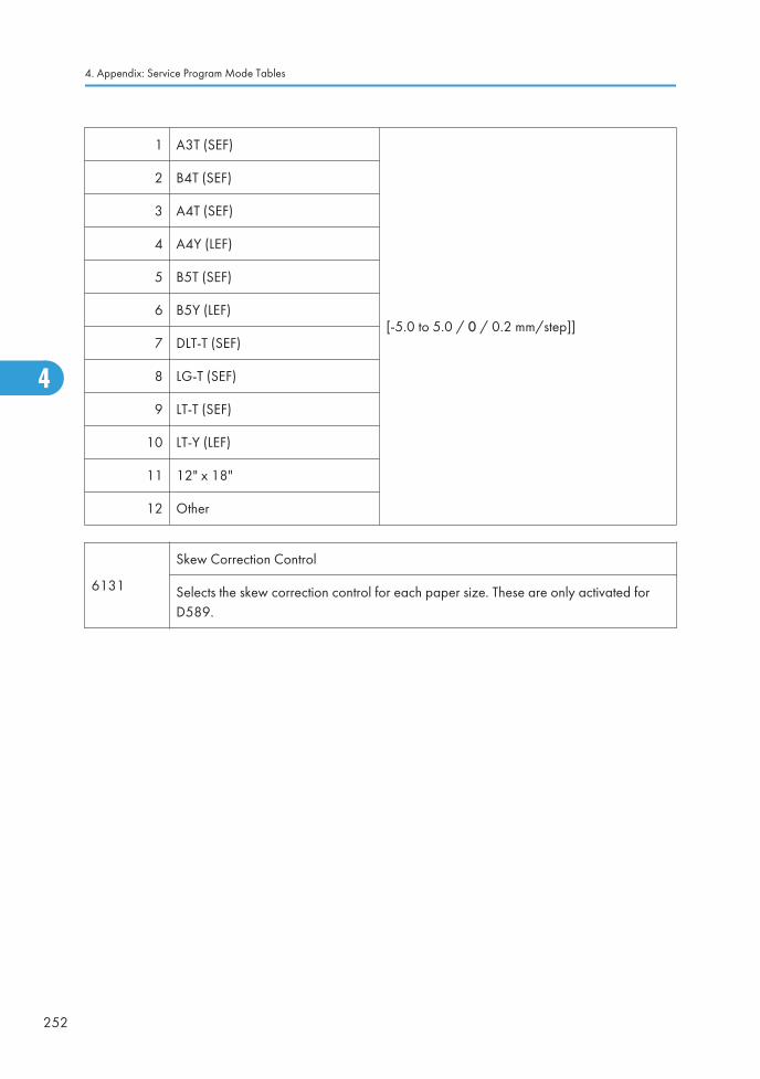
1 A3T (SEF)
[-5.0 to 5.0 / 0 / 0.2 mm/step]]
2 B4T (SEF)
3 A4T (SEF)
4 A4Y (LEF)
5 B5T (SEF)
6 B5Y (LEF)
7 DLT-T (SEF)
8 LG-T (SEF)
9 LT-T (SEF)
10 LT-Y (LEF)
11 12" x 18"
12 Other
6131
Skew Correction Control
Selects the skew correction control for each paper size. These are only activated forD589.
4. Appendix: Service Program Mode Tables
252
4

1 A3T (SEF)
[0 or 1 / 0 / 1/step]]
0: No (No skew correction)
1: Roller Stop Skew Correction
2 B4T (SEF)
3 A4T (SEF)
4 A4Y (LEF)
5 B5T (SEF)
6 B5Y (LEF)
7 DLT-T (SEF)
8 LG-T (SEF)
9 LT-T (SEF)
10 LT-Y (LEF)
11 12" x 18"
12 Other
6132
Jogger Fence Fine Adj
This SP adjusts the distance between the jogger fences and the sides of the stack on thefinisher stapling tray in the D585/D586/D589 finisher. The adjustment is doneperpendicular to the direction of paper feed.
System SP Tables-6
253
4

1 A3T (SEF)
[-1.5 to 1.5 / 0 / 0.5 /step]
+ Value: Increases distance between joggerfences and the sides of the stack.
- Value: Decreases the distance between thejogger fences and the sides of the stack.
2 B4T (SEF)
3 A4T (SEF)
4 A4Y (LEF)
5 B5T (SEF)
6 B5Y (LEF)
7 DLT-T (SEF)
8 LG-T (SEF)
9 LT-T (SEF)
10 LT-Y (LEF)
11 12" x 18"
12 Other
6133
Staple Position Adjustment
Adjusts the staple position for each finisher (D585/D586/D588/D589).
+ Value: Moves the staple position to the rear side.
- Value: Moves the staple position to the front side.
[-3.5 to 3.5 (D588/D589), -2.0 to 2.0 (D585/D586) / 0 / 0.5/step]
6134
Saddle Stitch Position Adjustment
Use this SP to adjust the stapling position of the booklet stapler when paper is stapledand folded in the Booklet Finisher D589.
4. Appendix: Service Program Mode Tables
254
4

1 A3T (SEF)
[-3.0 to 3.0 / 0 / 0.2 mm/step]
+ Value: Shifts staple position toward the crease.
- Value: Shifts staple position away from the crease.
2 B4T (SEF)
3 A4 T (SEF)
4 B5 T (SEF)
5 DLT-T (SEF)
6 LG-T (SEF)
7 LT-T (SEF)
8 12" x 18"
9 Other
6135
Folder Position Adjustment
This SP corrects the folding position when paper is stapled and folded in the BookletFinisher D589.
1 A3T (SEF)
[-3.0 to 3.0 / 0 / 0.2 mm/step]
+ Value: Shifts staple position toward the crease.
- Value: Shifts staple position away from the crease.
2 B4 T (SEF)
3 A4 T (SEF)
4 B5 T (SEF)
5 DLT-T (SEF)
6 LG-T (SEF)
7 LT-T (SEF)
8 12" x 18"
9 Other
6136
Folding Number
This SP sets the number of times the folding rollers are driven forward and reverse tosharpen the crease of a folded booklet before it exits the folding unit.
[2 to 30/ 2 /1 times]
System SP Tables-6
255
4

6137 Fin. Free Run
1 Free Run 1
D585/D589: Free run for paper edge stapling.
D588: System free run.
D586: Shift free run.
Remove the staple cartridge from D585/D589 finisher beforeperforming this SP.
2 Free Run 2
D588: Free run for durability testing.
D589: Free run for booklet stapling.
D586: Free run for paper edge stapling.
Remove the staple cartridge from D586/D589 finisher beforeperforming this SP.
3 Free Run 3D585/D586/D589: Shipping free run. Simulates standbyconditions during shipping.
4 Free Run 4 DFU
6138
FIN (TIG) Input Check 1000-Sheet Finisher D589
Note: The names in parentheses are the names used in the service manuals.
Component 0 1
1Interference Escape Sensor
(Stapler Safety Sensor)Inactive Active
2Staple Moving HP Sensor
(Staple Unit HP Sensor)Not HP At HP
3Stuck Relay1 Release HP Sensor
(Stopper S HP Sensor)Not HP At HP
4Exit Junction Gate HP Sensor
(Stack Feed Out HP Sensor)At HP Not HP
5Jogger HP Sensor
(Jogger Fence HP Sensor)Not HP At HP
6Staple Tray Paper Sensor
(Staple Tray Paper Sensor)No Paper Paper
4. Appendix: Service Program Mode Tables
256
4

7Rear Edge Fence HP Sensor
(Paper Stack Stopper HP Sensor)Not HP At HP
8 Saddle Stitch Exit Sensor Paper No Paper
9Stuck Relay2 Roller HP Sensor
(Clamp Roller HP Sensor)At HP Not HP
10Folder Tray Full Sensor 1
(Bottom Tray HP 1 Sensor)Full Not full
11Folder Tray Full Sensor 2
(Bottom Tray HP 2 Sensor)Not full Full
12Folder Plate HP Sensor
(Fold Plate HP Sensor)Not HP At HP
13Saddle Stitch Arrival Sensor
(Fold Unit Entrance Sensor)No Paper Paper
14Folder Cam HP Sensor
(Fold Plate Cam HP Sensor)Not HP At HP
15Staple Exit Sensor
(Stapler Tray Exit Sensor)Paper No Paper
16Shift Tray Paper Sensor
(Shift Tray Paper Position Sensor)No Tray Tray
17 Shift Tray Full Full Nor full
18 Shift Roller HP Sensor Not HP At HP
20 Entrance Sensor (Finisher Entrance Sensor) Paper No Paper
21Shift Exit Sensor
(Shift Tray Exit Sensor)No Paper Paper
22Proof Exit Sensor
(Proof Tray Exit Sensor)Paper No Paper
23 Exit Guide Plate HP Sensor Not HP At HP
System SP Tables-6
257
4

24Proof Full Sensor
(Proof Tray Full Sensor)Not full Full
25 Upper Cover Sensor Open Close
26 Door SW (Front Door Switch) Close Open
27 Clincher Timing Sensor Encoder
28 Clincher HP Sensor At HP Not HP
29 Driver Timing Sensor Encoder
30 Staple Near End Staples Remain Staples N.E.
31 Self Priming Staples No Staples
32 Driver HP Sensor At HP Not HP
33 Punch Registration Detection HP Sensor Not HP At HP
34Punch Moving HP Sensor
(Punch Movement HP Sensor)Not HP At HP
35Punch HP Sensor
(Punch HP Sensor)At HP Not HP
36Punch Pulse Count Sensor
(Punch Encoder Sensor)Encoder
37Punch Chad Full Sensor
(Punch Hopper Full Sensor)Not full Full
38Punch Registration Detection Sensor (PaperPosition Sensor)
Paper No Paper
6139
FIN (KIN) Input Check 1000-Sheet Finisher D588
Note: The names in parentheses are the names used in the service manuals.
Component 0 1
1 Entrance Sensor Paper No Paper
2Shift Exit Sensor
(Lower Tray Exit Sensor)No Paper Paper
4. Appendix: Service Program Mode Tables
258
4

3Staple Entrance Sensor
(Stapler Tray Entrance Sensor)Paper No Paper
4Staple Moving HP Sensor
(Stapler HP Sensor)Not HP At HP
5Jogger HP Sensor
(Jogger Fence HP Sensor)Not HP At HP
6 Stack Feed-out Belt HP Sensor At HP Not HP
7 Staple Tray Paper Sensor No Paper Paper
8Staple Rotation Sensor
(Staple Rotation HP Sensor)Not HP At HP
9 Staple Sensor Staples No Staples
10 Staple READY Detection Staples No Staples
11Exit Guide Plate HP
(Exit Guide Plate HP Sensor)Not HP At HP
12 Shift HP Sensor Not HP At HP
13Paper Sensor
(Stack Height Sensor)No Tray Tray
14Tray Lower Sensor
(Lower Tray Lower Limit Sensor)Lower limit Not Lower Limit
15Proof Full Sensor
(Paper Limit Sensor)Not Full Full
6141
FIN (ELB) Input Check 500-Sheet Finisher D585
Displays the signals received from sensors and switches of the finisher.
Note:
• The names in parentheses below are the names used in the service manuals.
"0" means LOW, "1" means HIGH.
Component 0 1
System SP Tables-6
259
4

1 Entrance Sensor Paper No Paper
2Hitroll HP Sensor
(Positioning Roller HP Sensor)Not HP At HP
3Front Jogger HP Sensor
(Front Fence HP Sensor)Not HP At HP
4Rear Jogger HP Sensor
(Rear Fence HP Sensor)Not HP At HP
5 Staple Tray Paper Sensor Paper No Paper
6Staple Moving HP Sensor
(Stapler HP Sensor)Not HP At HP
7 Stack Feed-Out Belt HP Sensor Not HP At HP
8 Shift Tray Paper Sensor Not HP At HP
9 Upper Cover Sensor Not HP At HP
10 Stapler Rotation Sensor HP Not HP
11 Staple Near End Sensor HP Not HP
12 Self Priming (Stapler) HP Not HP
13Shift Tray Limit Sensor
(Tray Upper Limit SW)Not Full Full
6142
FIN (RUB) Input Check Inner Finisher D586
Displays the signals received from sensors and switches of the finisher.
Note:
• The names in parentheses below are the names used in the service manuals.
"0" means LOW, "1" means HIGH.
Component 0 1
1 Entrance Sensor
2Carry Sensor
(Feed Sensor)
4. Appendix: Service Program Mode Tables
260
4

3Exit Sensor
(Paper Exit Sensor)
4 Staple Tray Paper Sensor
5Front Jogger HP Sensor
(Jogger Fence HP Sensor (Front))
6Rear Jogger HP Sensor
(Jogger Fence HP Sensor (Back))
7Sft Roller HP Sensor
(Shift Roller HP Sensor)
8 Hitroll HP Sensor
9 Ext Guide Plate HP Sensor
10 Staple Moving HP Sensor
11 Shift Tray Paper Sensor
12 Shift Tray Limit Sensor
13 Staple Rotation Sensor
14 Staple Near End Sensor
15 Self Priming Sensor
16 Stopper HP Sensor
17 Punch HP Sensor
18 Punch Pluse Count Sensor
19 Punch Chad Full Sensor
20 Punch Moving HP Sensor
21 Punch Registration Detection HP Sensor
22 Punch Registration Detection Sensor
23 Slide Door SW
24 Shift Tray Upper Limit SW
System SP Tables-6
261
4
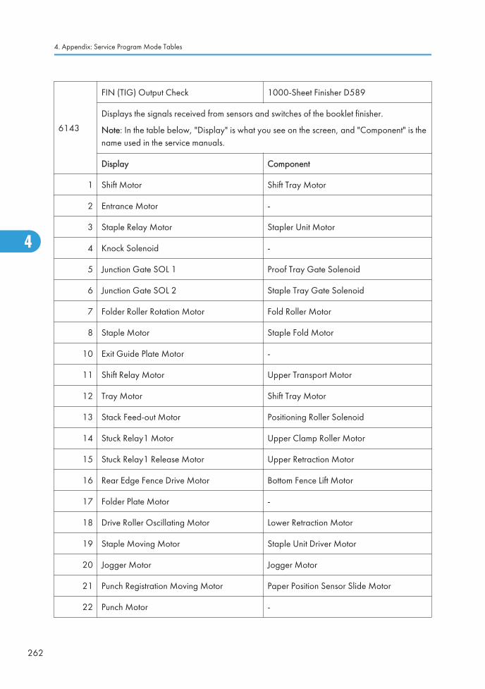
6143
FIN (TIG) Output Check 1000-Sheet Finisher D589
Displays the signals received from sensors and switches of the booklet finisher.
Note: In the table below, "Display" is what you see on the screen, and "Component" is thename used in the service manuals.
Display Component
1 Shift Motor Shift Tray Motor
2 Entrance Motor -
3 Staple Relay Motor Stapler Unit Motor
4 Knock Solenoid -
5 Junction Gate SOL 1 Proof Tray Gate Solenoid
6 Junction Gate SOL 2 Staple Tray Gate Solenoid
7 Folder Roller Rotation Motor Fold Roller Motor
8 Staple Motor Staple Fold Motor
10 Exit Guide Plate Motor -
11 Shift Relay Motor Upper Transport Motor
12 Tray Motor Shift Tray Motor
13 Stack Feed-out Motor Positioning Roller Solenoid
14 Stuck Relay1 Motor Upper Clamp Roller Motor
15 Stuck Relay1 Release Motor Upper Retraction Motor
16 Rear Edge Fence Drive Motor Bottom Fence Lift Motor
17 Folder Plate Motor -
18 Drive Roller Oscillating Motor Lower Retraction Motor
19 Staple Moving Motor Staple Unit Driver Motor
20 Jogger Motor Jogger Motor
21 Punch Registration Moving Motor Paper Position Sensor Slide Motor
22 Punch Motor -
4. Appendix: Service Program Mode Tables
262
4

23 Punch Moving Motor Punch Movement Motor
6144
FIN (KIN) Output Check 1000-Sheet Finisher D588
Displays the signals received from sensors and switches of the booklet finisher.
Note: In the table below, "Display" is what you see on the screen, and "Component" isthe name used in the service manuals.
Display Component
1 Relay Up Motor Upper Transport Motor
2 Relay Down Motor Lower Transport Motor
3 Exit Motor -
4 Proof Junction Gate SOL Tray Junction Gate Solenoid
5 Tray Up Motor Lower Tray Lift Motor
6 Jogger Motor Jogger Fence Motor
7 Staple Moving Motor Stapler Motor
8 Staple Motor Stapler Hammer
9 Staple Junction Gate SOL Stapler Junction Gate Solenoid
10 Positioning Roller Solenoid Positioning Roller Solenoid
11 Stack Feed-out Motor -
12 Shift Motor -
13 Exit Guide Plate Motor -
6146
FIN (ELB) Output Check 500-Sheet Finisher D585
Displays the signals received from sensors and switches of the finisher.
Note: In the table below, "Display" is what you see on the screen, and "Component" isthe name used in the service manuals.
Display Component
1 Carry Motor Transport Motor
2 Hitroll Motor Positioning Roller Arm Motor
System SP Tables-6
263
4

3 Front Jogger Motor Front Fence Motor
4 Rear Jogger Motor Rear Fence Motor
5 Staple Moving Motor Stapler Movement Motor
6 Stack Feed-Out Motor Feed-Out Belt Motor
7 Tray Motor Tray Lift Motor
8 Staple Motor Stapler Motor
9 Stopper Solenoid Stack Depressor Solenoid
6147
FIN (RUB) Output Check 500-Sheet Finisher D586
Displays the signals received from sensors and switches of the finisher.
Note: In the table below, "Display" is what you see on the screen, and "Component" isthe name used in the service manuals.
Display Component
1 Entrance Motor Entrance Roller Motor
2 Carry Motor Feed Roller Motor
3 Exit Motor Exit Roller Motor
4 Front Jogger Motor Jogger Fence Motor (Front)
5 Rear Jogger Motor Jogger Fence Motor (Back)
6 Shift Motor Shift Roller Motor
7 Hitroll Motor Pick-up Roller Motor
8 Exit Guide Plate Motor Exit Guide Plate Motor
9 Staple Moving Motor Stapler Unit Motor
10 Tray Motor Output Tray Motor
11 Staple Motor Stapler Unit Motor
12 Stopper Motor Stack height detection lever Motor
13 Punch Motor Punch Drive Motor
14 Punch Moving Motor Punch Movement Motor
4. Appendix: Service Program Mode Tables
264
4

15 Punch Registration Moving Motor Paper Position Sensor Unit Motor
6150
Input Check
Displays the signals received from sensors and switches of the bridge unit.
Component 0 1
1 Relay: Paper Exit Sensor Paper detected Paper not detected
2 Relay: Paper Feed Sensor Paper detected Paper not detected
3 Relay/Shift Unit Set Set Not set
4 Relay: Exit Cover Sensor Closed Open
5 Relay: Feed Cover Sensor Closed Open
6151
OUTPUT Check
Displays the signals received from sensors and switches of the bridge unit.
Display Description
1 Relay: Feed Motor: Reset Bridge Unit: Feed Motor: Enable
2 Relay: Feed Motor: Enable Bridge Unit: Feed Motor: CCW: High
3 Relay: Feed Motor: CCW: High Bridge Unit: Feed Motor: CCW: Low
4 Relay: Feed Motor: CCW: Low Bridge Unit: Junction Gate SOL
5 Relay: Junction Gate SOL Bridge Unit: Feed Motor: Reset
6152
Input Check
Displays the signals received from sensors and switches of the bridge unit.
Component 0 1
2 ShiftTray: Position Sensor Tray position: front Tray position: rear
System SP Tables-6
265
4

6153
OUTPUT Check
Displays the signals received from sensors and switches of the shift tray.
Display Description
1 ShiftTray: Motor -
6154
INPUT Check
Displays the signals received from sensors and switches of the bridge unit.
Component 0 1
1 1 bin: Set Detection Set Not set
2 1BIN: Paper Feed Sensor Paper detected Paper not detected
3 1BIN: Paper Remain
6155
OUTPUT Check
Displays the signals received from sensors and switches of the 1-bin tray.
Display Description
1 1BIN: Reversal Output Signal -
6800
Sheet Conversion (Thick Paper)
Allows the punch feature in Z-hold mode.
[1 to 3 / 3 / 1]
1: 1 sheet
2: 2 sheets
3: 3 sheets
4. Appendix: Service Program Mode Tables
266
4

6830*
Extra Staples
More than the standard number of sheets can be stapled. This SP sets the additionalnumber of sheets (This Setting + Standard Number = maximum number of sheets).
• If the number of the maximum for staples is increased, and the mechanicalwarranty of the unit can be guaranteed, then the setting can take effect withoutchanging the controller software.
• However, assurance that mechanical performance can be guaranteed is requiredbefore changing the setting to increase the staple load for more than the maximumin the feed/exit specifications. Raising this setting without quality assurance coulddamage the machine.
1Staple positions other than booklet stapling
[0 to 50 / 0 /1]
22 Booklet stapling
[0 to 50 / 0 /1]
System SP Tables-6
267
4

System SP Tables-7
SP7xxx: Data Log
7401*Total SC Counter
Displays the total number of service calls that have occurred.
7403* SC History
1 Latest
Displays the most recent 10 service calls.
2 Latest 1
3 Latest 2
4 Latest 3
5 Latest 4
6 Latest 5
7 Latest 6
8 Latest 7
9 Latest 8
10 Latest 9
7404* SC991 History
4. Appendix: Service Program Mode Tables
268
4

1 Latest
Displays the 10 most recently detected SC991 codes.
2 Latest 1
3 Latest 2
4 Latest 3
5 Latest 4
6 Latest 5
7 Latest 6
8 Latest 7
9 Latest 8
10 Latest 9
7504*
Paper Jam Loc
ON: On check, OFF: Off Check
Displays the number of jams according to the location where jams were detected.
NOTE: The LCT is counted as the 3rd feed station.
1 At Power On
3 Tray 1: On
4 Tray 2: On
5 Tray 3: On
6 Tray 4: On
8 Bypass: On
9 Duplex: On
11 Vertical Trans. 1: On
12 Vertical Trans .2: On
13 Vertical Trans .3: On
17 Registration: On
System SP Tables-7
269
4

20 Paper Exit: On
21 Bridge Tray Exit: On
22 Bridge Relay: On
24 Inverter: On
25 Duplex Exit: On
27 Duplex Entrance: On
51 Vertical Trans. 1: Off
52 Vertical Trans. 2: Off
53 Vertical Trans. 3 (PFU): Off
54 Vertical Trans. 4 (PFU): Off
57 Registration Sensor: Off
60 Paper Exit: Off
61 Bridge Tray Exit: Off
62 Bridge Relay: Off
64 Inverter: Off
65 Duplex Exit: Off
67 Duplex Ent: Off
100 Finisher Entrance: KIN (D588)
101 Finisher Shift Tray Exit: KIN (D588)
102 Finisher Staple: KIN (D588)
103 Finisher Exit: KIN (D588)
105 Finisher Tray Lift Motor: KIN (D588)
106 Finisher Jogger Motor: KIN (D588)
107 Finisher Shift Motor: KIN (D588)
108 Finisher Staple Motor: KIN (D588)
109 Finisher Exit Motor : KIN (D588)
4. Appendix: Service Program Mode Tables
270
4

130 FIN Entrance: TIG (D589)
131 FIN Proof Tray Exit: TIG (D589)
132 FIN Shift Tray: TIG (D589)
133 FIN Staple Exit: TIG (D589)
134 FIN Exit: TIG (D589)
135 Finisher Fold: TIG (D589)
136 FIN Fold Exit: TIG (D589)
137 Exit Guide Gate Motor: TIG (D589)
138 FIN Staple Shift Motor: TIG (D589)
139 FIN Paper Punch Motor: TIG (D589)
140 FIN Tray Lift Motor: TIG (D589)
141 FIN Jogger Motor: TIG (D589)
142 FIN Shift Motor: TIG (D589)
143 FIN Fold Plate Motor: TIG (D589)
144 FIN Staple Motor: TIG (D589)
145 FIN Exit Motor: TIG (D589)
146 FIN Stack 1 Release Motor: TIG (D589)
147 FIN Stack 2 Release Motor: TIG (D589)
148 FIN Stopper Motor: TIG (D589)
160 Entrance Sn:ON
161 Entrance Sn: OFF
162 FIN Entrance
163 Positioning Roller
164 Front Jogger Motor
165 Rear Jogger Motor
166 Exit Motor
System SP Tables-7
271
4

167 FIN Staple Shift Motor: ELB (D585)
168 FIN Staple Motor: ELB (D585)
169 FIN Tray Lift Motor: ELB (D585)
170 FIN Stack Height SOL: ELB (D585)
190 FIN Entrance: ON: RUB (D586)
191 FIN Entrance: OFF: RUB (D586)
192 FIN Trans ON: RUB (D586)
193 FIN Trans: OFF: RUB (D586)
194 FIN Entrance: RUB (D586)
195 FIN Front Jogger Motor: RUB (D586)
196 FIN Rear Jogger Motor: RUB (D586)
197 FIN Shift Roller Motor: RUB (D586)
198 FIN Positioning Roller: RUB (D586)
199 FIN Paper Exit Plate Motor: RUB (D586)
200 FIN Staple Shift Motor: RUB (D586)
201 FIN Tray Lift Motor: RUB (D586)
202 FIN Staple Motor: RUB (D586)
203 FIN Stack Height SOL: RUB (D586)
204 FIN Punch Motor: RUB (D586)
205 FIN Punch Movement Motor: RUB (D586)
206 FIN Registration Motor: RUB (D586)
230 Fin Exit
231 Insufficient Data
4. Appendix: Service Program Mode Tables
272
4

7505*
Original Jam Det
Displays the total number of original jams by location. These jams occur when theoriginal does not activate the sensors.
Note
• Lag. Jam occurs when the paper remains at the sensor for longer than theprescribed time.
• Late: Jam occurs because paper fails to arrive at the prescribed time.
1 At Power On
3 Skew Correction Sensor: On
4 Registration Sensor: On
5 Original Exit Sensor: On
53 Skew Correction Sensor: Off
54 Registration Sensor: Off
55 Original Exit Sensor: Off
7506* Jam Count by Paper Size
System SP Tables-7
273
4

5 A4 LEF
Displays the total number of copy jams by paper size.
6 A5 LEF
14 B5 LEF
38 LT LEF
44 HLT LEF
132 A3 SEF
133 A4 SEF
134 A5 SEF
141 B4 SEF
142 B5 SEF
160 DLT SEF
164 LG SEF
166 LT SEF
172 HLT SEF
255 Others
7507* Plotter Jam History
4. Appendix: Service Program Mode Tables
274
4

1 LatestDisplays the copy jam history (the most recent 10 jams)
Sample Display:
CODE:007
SIZE:05h
TOTAL:0000334
DATE: Mon Mar 15 11:44:50 2000
where:
CODE is the SP7504-*** number (see above.
SIZE is the ASAP paper size code in hex.
TOTAL is the total jam error count (SP7502)
DATE is the date the jams occurred.
2 Latest 1
3 Latest 2
4 Latest 3
5 Latest 4
6 Latest 5
7 Latest 6
8 Latest 7
9 Latest 8
10 Latest 9
Size Code Size Code Size Code
A4 (S) 05 A3 (L) 84 DLT (L) A0
A5 (S) 06 A4 (L) 85 LG (L) A4
B5 (S) 0E A5 (L) 86 LT (L) A6
LT (S) 26 B4 (L) 8D HLT (L) AC
HLT (S) 2C B5 (L) 8E Others FF
7508* Original Jam History
System SP Tables-7
275
4

1 LatestDisplays the original jam history (the most recent 10 jams).
Sample Display:
CODE:007
SIZE:05h
TOTAL:0000334
DATE: Mon Mar 15 11:44:50 2000
where:
CODE is the SP7505*** number (see above.
SIZE is the ASAP paper size code in hex.
TOTAL is the total error count (SP7503)
DATE is the date the jams occurred.
2 Latest 1
3 Latest 2
4 Latest 3
5 Latest 4
6 Latest 5
7 Latest 6
8 Latest 7
9 Latest 8
10 Latest 9
7624* Parts Replacement Operation ON/OFF
1 PCU
[0 or 1 / 1 / -]
0: No (Not PM maintenance)
1: Yes (PM maintenance)
7801
ROM No./Firmware Version
This SP codes display the firmware versions of all ROMs in the system, including themainframe, the ARDF, and peripheral devices.
7803*PM Counter Display
Displays the PM counter since the last PM.
1 Paper
2 Sheets 60K Part
3 Sheets 120K Part
4 Distance (mm) 60 K
5 Distance (mm) 120 K
6 Distance 60K
4. Appendix: Service Program Mode Tables
276
4

7 Distance 120K
7804PM Counter Resets
Resets the PM counter. To reset, press Execute on the touch panel.
1 Paper
2 60K part
3 120K part
7807
SC/Jam Counter Reset
Resets the SC and jam counters. To reset, press Execute on the touch panel.
This SP does not reset the jam history counters: SP7507, SP7508.
7826*MF Error Counter Japan Only
Displays the number of counts requested of the card/key counter.
1 Error TotalA request for the count total failed at power on. This error will occurif the device is installed but disconnected.
2 Error StapleThe request for a staple count failed at power on. This error willoccur if the device is installed but disconnected.
7827MF Error Counter Clear Japan Only
Press Execute to reset to 0 the values of SP7826. Japan Only
7832
Self-Diagnose Result Display
Execute to open the "Self-Diagnostics Result Display" to view details about errors. Usethe keys in the display on the touch-panel to scroll through all the information. If noerrors have occurred, you will see the "No Error" message on the screen.
7836Total Memory Size
Displays the memory capacity of the controller system.
System SP Tables-7
277
4

7852*
DF Glass Dust Check
Counts the number of occurrences (0 to 65,535) when dust was detected on thescanning glass of the ADF.
1* Dust Detection CounterCounts the occurrences. Counting is done only ifSP4020 1 (ADF Scan Glass Dust Check) is switchedon.
2*Dust Detection ClearCounter
Clears the count. Memory All Clear (SP5801) resetsthis counter to zero.
7856*Zero Cross
Stores and displays the detected zero cross frequency for main power ac.
7901*
Assert Info. DFU
These SP numbers display the results of the occurrence of the most recent SC codegenerated by the machine.
1* File Name Module name
2* Number of Lines Number of the lines where error occurred.
3* Location Value
7906
Last PM Count
Displays the most recent PM count for 60K and 120K service parts ("60K" and"120" refer to service life).
2 Sheets 60K Part
3 Sheets 120K Part
4 Distance (mm) 60 K
5 Distance (mm) 120 K
6 Distance 60K
7 Distance 120K
4. Appendix: Service Program Mode Tables
278
4

7907
Before 2 PM Count
Displays the PM count before the most recent PM count for 60K and 120K serviceparts ("60K" and "120" refer to service life).
2 Sheets 60K Part
3 Sheets 120K Part
4 Distance (mm) 60 K
5 Distance (mm) 120 K
6 Distance 60K
7 Distance 120K
7908
Before 3 PM Count
Displays the PM count two counts the most recent PM count for 60K and 120Kservice parts ("60K" and "120" refer to service life).
Sheets 60K Part
3 Sheets 120K Part
4 Distance (mm) 60 K
5 Distance (mm) 120 K
6 Distance 60K
7 Distance 120K
System SP Tables-7
279
4
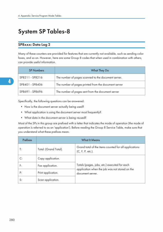
System SP Tables-8
SP8xxx: Data Log 2
Many of these counters are provided for features that are currently not available, such as sending colorfaxes, and so on. However, here are some Group 8 codes that when used in combination with others,can provide useful information.
SP Numbers What They Do
SP8211 - SP8216 The number of pages scanned to the document server.
SP8401 - SP8406 The number of pages printed from the document server
SP8691 - SP8696 The number of pages sent from the document server
Specifically, the following questions can be answered:
• How is the document server actually being used?
• What application is using the document server most frequently?
• What data in the document server is being reused?
Most of the SPs in this group are prefixed with a letter that indicates the mode of operation (the mode ofoperation is referred to as an 'application'). Before reading the Group 8 Service Table, make sure thatyou understand what these prefixes mean.
Prefixes What It Means
T: Total: (Grand Total).Grand total of the items counted for all applications(C, F, P, etc.).
C: Copy application.
Totals (pages, jobs, etc.) executed for eachapplication when the job was not stored on thedocument server.
F: Fax application.
P: Print application.
S: Scan application.
4. Appendix: Service Program Mode Tables
280
4

Prefixes What It Means
L:Local storage (documentserver)
Totals (jobs, pages, etc.) for the document server. TheL: counters work differently case by case. Sometimes,they count jobs/pages stored on the document server;this can be in document server mode (from thedocument server window), or from another mode, suchas from a printer driver or by pressing the Store Filebutton in the Copy mode window. Sometimes, theyinclude occasions when the user uses a file that isalready on the document server. Each counter will bediscussed case by case.
O:Other applications (externalnetwork applications, forexample)
Refers to network applications such as Web ImageMonitor. Utilities developed with the SDK (SoftwareDevelopment Kit) will also be counted with this groupin the future.
The Group 8 SP codes are limited to 17 characters, forced by the necessity of displaying them on thesmall LCDs of printers and faxes that also use these SPs. Read over the list of abbreviations below andrefer to it again if you see the name of an SP that you do not understand.
Key for Abbreviations
Abbreviation What It Means
/ "By", e.g. "T:Jobs/Apl" = Total Jobs "by" Application
> More (2> "2 or more", 4> "4 or more"
AddBook Address Book
Apl Application
B/W Black & White
Bk Black
C Cyan
ColCr Color Create
ColMode Color Mode
Comb Combine
Comp Compression
System SP Tables-8
281
4

Abbreviation What It Means
Deliv Delivery
DesAplDesignated Application. The application (Copy, Fax, Scan, Print) used to storethe job on the document server, for example.
Dev Counter Development Count, no. of pages developed.
Dup, Duplex Duplex, printing on both sides
Emul Emulation
FC Full Color
FIN Post-print processing, i.e. finishing (punching, stapling, etc.)
Full Bleed No Margins
GenCopy Generation Copy Mode
GPCGet Print Counter. For jobs 10 pages or less, this counter does not count up. Forjobs larger than 10 pages, this counter counts up by the number that is in excessof 10 (e.g., for an 11-page job, the counter counts up 11-10 =1)
IFax Internet Fax
ImgEdtImage Edit performed on the original with the copier GUI, e.g. border removal,adding stamps, page numbers, etc.
K Black (YMCK)
LS Local Storage. Refers to the document server.
LSize Large (paper) Size
Mag Magnification
MC One color (monochrome)
NRSNew Remote Service, which allows a service center to monitor machinesremotely. "NRS" is used overseas, "CSS" is used in Japan.
Org Original for scanning
OrgJam Original Jam
4. Appendix: Service Program Mode Tables
282
4

Abbreviation What It Means
Palm 2Print Job Manager/Desk Top Editor: A pair of utilities that allows print jobs to bedistributed evenly among the printers on the network, and allows files to movedaround, combined, and converted to different formats.
PC Personal Computer
PGSPages. A page is the total scanned surface of the original. Duplex pages countas two pages, and A3 simplex count as two pages if the A3/DLT counter SP isswitched ON.
PJob Print Jobs
Ppr Paper
PrtJam Printer (plotter) Jam
PrtPGS Print Pages
RRed (Toner Remaining). Applies to the wide format model A2 only. This machineis under development and currently not available.
Rez Resolution
SC Service Code (Error SC code displayed)
Scn Scan
Sim, Simplex Simplex, printing on 1 side.
S-to-Email Scan-to-E-mail
SMCSMC report printed with SP5990. All of the Group 8 counters are recorded inthe SMC report.
Svr Server
TonEnd Toner End
TonSave Toner Save
TXJob Send, Transmission
YMC Yellow, Magenta, Cyan
YMCK Yellow, Magenta, Cyan, BlacK
System SP Tables-8
283
4

• All of the Group 8 SPs are reset with SP5 801 1 Memory All Clear.
8001 T:Total JobsThese SPs count the number of times each application isused to do a job.
[0 to 9999999/ 0 / 1]
Note: The L: counter is the total number of times the otherapplications are used to send a job to the document server,plus the number of times a file already on the documentserver is used.
8002 C:Total Jobs
8003 F:Total Jobs
8004 P:Total Jobs
8005 S:Total Jobs
8006 L:Total Jobs
• These SPs reveal the number of times an application is used, not the number of pages processed.
• When an application is opened for image input or output, this counts as one job.
• Interrupted jobs (paper jams, etc.) are counted, even though they do not finish.
• Only jobs executed by the customer are counted. Jobs executed by the customer engineer usingthe SP modes are not counted.
• When using secure printing (when a password is required to start the print job), the job is countedat the time when either "Delete Data" or "Specify Output" is specified.
• A job is counted as a fax job when the job is stored for sending.
• When a fax is received to fax memory, the F: counter increments but the L: counter does not (thedocument server is not used).
• A fax broadcast counts as one job for the F: counter (the fax destinations in the broadcast are notcounted separately).
• A fax broadcast is counted only after all the faxes have been sent to their destinations. If onetransmission generates an error, then the broadcast will not be counted until the transmission hasbeen completed.
• A printed fax report counts as one job for the F: counter.
• The F: counter does not distinguish between fax sending or receiving.
• When a copy job on the document server is printed, SP8022 also increments, and when a printjob stored on the document server is printed, SP8024 also increments.
• When an original is both copied and stored on the document server, the C: and L: counters bothincrement.
• When a print job is stored on the document server, only the L: counter increments.
• When the user presses the Document Server button to store the job on the document server, onlythe L: counter increments.
4. Appendix: Service Program Mode Tables
284
4

• When the user enters document server mode and prints data stored on the document server, onlythe L: counter increments.
• When an image received from Palm 2 is received and stored, the L: counter increments.
• When the customer prints a report (user code list, for example), the O: counter increments.However, for fax reports and reports executed from the fax application, the F: counter increments.
8011 T:Jobs/LS
These SPs count the number of jobs stored to the documentserver by each application, to reveal how local storage isbeing used for input.
[0 to 9999999/ 0 / 1]
The L: counter counts the number of jobs stored from withinthe document server mode screen at the operation panel.
8012 C:Jobs/LS
8013 F:Jobs/LS
8014 P:Jobs/LS
8015 S:Jobs/LS
8016 L:Jobs/LS
8017 O:Jobs/LS
• When a scan job is sent to the document server, the S: counter increments. When you enterdocument server mode and then scan an original, the L: counter increments.
• When a print job is sent to the document server, the P: counter increments.
• When a network application sends data to the document server, the O: counter increments.
• When an image from Palm 2 is stored on the document server, the O: counter increments.
• When a fax is sent to the document server, the F: counter increments.
8021 T:Pjob/LS
These SPs reveal how files printed from the document serverwere stored on the document server originally.
[0 to 9999999/ 0 / 1]
The L: counter counts the number of jobs stored from withinthe document server mode screen at the operation panel.
8022 C:Pjob/LS
8023 F:Pjob/LS
8024 P:Pjob/LS
8025 S:Pjob/LS
8026 L:Pjob/LS
8027 O:Pjob/LS
• When a copy job stored on the document server is printed with another application, the C: counterincrements.
System SP Tables-8
285
4

• When an application like DeskTopBinder merges a copy job that was stored on the documentserver with a print job that was stored on the document server, the C: and P: counters bothincrement.
• When a job already on the document server is printed with another application, the L: counterincrements.
• When a scanner job stored on the document server is printed with another application, the S:counter increments. If the original was scanned from within document server mode, then the L:counter increments.
• When images stored on the document server by a network application (including Palm 2), areprinted with another application, the O: counter increments.
• When a copy job stored on the document server is printed with a network application (Web ImageMonitor, for example), the C: counter increments.
• When a fax on the document server is printed, the F: counter increments.
8031 T:Pjob/DesApl
These SPs reveal what applications were used to outputdocuments from the document server.
[0 to 9999999/ 0 / 1]
The L: counter counts the number of jobs printed from withinthe document server mode screen at the operation panel.
8032 C:Pjob/DesApl
8033 F:Pjob/DesApl
8034 P:Pjob/DesApl
8035 S:Pjob/DesApl
8036 L:Pjob/DesApl
8037 O:Pjob/DesApl
• When documents already stored on the document server are printed, the count for the applicationthat started the print job is incremented.
• When the print job is started from a network application (Desk Top Binder, Web Image Monitor,etc.) the L: counter increments.
4. Appendix: Service Program Mode Tables
286
4

8041 T:TX Jobs/LS These SPs count the applications that stored files on thedocument server that were later accessed fortransmission over the telephone line or over a network(attached to an e-mail, or as a fax image by I-Fax).
[0 to 9999999/ 0 / 1]
Note:
• Jobs merged for sending are counted separately.
• The L: counter counts the number of jobs scannedfrom within the document server mode screen atthe operation panel.
8042 C:TX Jobs/LS
8043 F:TX Jobs/LS
8044 P:TX Jobs/LS
8045 S:TX Jobs/LS
8046 L:TX Jobs/LS
8047 O:TX Jobs/LS
• When a stored copy job is sent from the document server, the C: counter increments.
• When images stored on the document server by a network application or Palm2 are sent as an e-mail, the O: counter increments.
8051 T:TX Jobs/DesAplThese SPs count the applications used to send filesfrom the document server over the telephone line orover a network (attached to an e-mail, or as a faximage by I-Fax). Jobs merged for sending are countedseparately.
[0 to 9999999/ 0 / 1]
The L: counter counts the number of jobs sent fromwithin the document server mode screen at theoperation panel.
8052 C:TX Jobs/DesApl
8053 F:TX Jobs/DesApl
8054 P:TX Jobs/DesApl
8055 S:TX Jobs/DesApl
8056 L:TX Jobs/DesApl
8057 O:TX Jobs/DesApl
• If the send is started from Desk Top Binder or Web Image Monitor, for example, then the O:counter increments.
8061
T:FIN Jobs [0 to 9999999/ 0 / 1]
These SPs total the finishing methods. The finishing method is specified by theapplication.
8062
C:FIN Jobs [0 to 9999999/ 0 / 1]
These SPs total finishing methods for copy jobs only. The finishing method isspecified by the application.
System SP Tables-8
287
4

8063
F:FIN Jobs [0 to 9999999/ 0 / 1]
These SPs total finishing methods for fax jobs only. The finishing method isspecified by the application.
Note: Finishing features for fax jobs are not available at this time.
8064
P:FIN Jobs [0 to 9999999/ 0 / 1]
These SPs total finishing methods for print jobs only. The finishing method isspecified by the application.
8065
S:FIN Jobs [0 to 9999999/ 0 / 1]
These SPs total finishing methods for scan jobs only. The finishing method isspecified by the application.
Note: Finishing features for scan jobs are not available at this time.
8066
L:FIN Jobs [0 to 9999999/ 0 / 1]
These SPs total finishing methods for jobs output from within the document servermode screen at the operation panel. The finishing method is specified from theprint window within document server mode.
8067
O:FIN Jobs [0 to 9999999/ 0 / 1]
These SPs total finishing methods for jobs executed by an external application,over the network. The finishing method is specified by the application.
1 SortNumber of jobs started in Sort mode. When a stored copy job isset for Sort and then stored on the document server, the L: counterincrements. (See SP8066 1)
2 Stack Number of jobs started out of Sort mode.
3 Staple Number of jobs started in Staple mode.
4 BookletNumber of jobs started in Booklet mode. If the machine is in staplemode, the Staple counter also increments.
5 Z-FoldNumber of jobs started In any mode other than the Booklet modeand set for folding (Z-fold).
6 PunchNumber of jobs started in Punch mode. When Punch is set for aprint job, the P: counter increments. (See SP8064 6.)
7 Other Reserved. Not used.
4. Appendix: Service Program Mode Tables
288
4

8 Inside-Fold Half-Fold Not Used
9Three-IN-Fold
Letter Fold-in Not Used
10Three-OUT-Fold
Letter Fold-out Not Used
11 Four-Fold Double Parallel Fold Not Used
12KANNON-Fold
Gate Fold Not Used
13 Perfect-Bind Perfect Binder Not Used
14 Ring-Bind Ring Binder Not Used
8071
T:Jobs/PGS [0 to 9999999/ 0 / 1]
These SPs count the number of jobs broken down by the number of pages in thejob, regardless of which application was used.
8072
C:Jobs/PGS [0 to 9999999/ 0 / 1]
These SPs count and calculate the number of copy jobs by size based on thenumber of pages in the job.
8073
F:Jobs/PGS [0 to 9999999/ 0 / 1]
These SPs count and calculate the number of fax jobs by size based on thenumber of pages in the job.
8074
P:Jobs/PGS [0 to 9999999/ 0 / 1]
These SPs count and calculate the number of print jobs by size based on thenumber of pages in the job.
8075
S:Jobs/PGS [0 to 9999999/ 0 / 1]
These SPs count and calculate the number of scan jobs by size based on thenumber of pages in the job.
8076
L:Jobs/PGS [0 to 9999999/ 0 / 1]
These SPs count and calculate the number of jobs printed from within thedocument server mode window at the operation panel, by the number of pages inthe job.
System SP Tables-8
289
4

8077
O:Jobs/PGS [0 to 9999999/ 0 / 1]
These SPs count and calculate the number of "Other" application jobs (WebImage Monitor, Palm 2, etc.) by size based on the number of pages in the job.
1 1 Page 8 21 to 50 Pages
2 2 Pages 9 51 to 100 Pages
3 3 Pages 10 101 to 300 Pages
4 4 Pages 11 301 to 500 Pages
5 5 Pages 12 501 to 700 Pages
6 6 to10 Pages 13 701 to 1000 Pages
7 11 to 20 Pages 14 More than 1001 Pages
• For example: When a copy job stored on the document server is printed in document server mode,the appropriate L: counter (SP8076 0xx) increments.
• Printing a fax report counts as a job and increments the F: counter (SP 8073).
• Interrupted jobs (paper jam, etc.) are counted, even though they do not finish.
• If a job is paused and re-started, it counts as one job.
• If the finisher runs out of staples during a print and staple job, then the job is counted at the time theerror occurs.
• For copy jobs (SP 8072) and scan jobs (SP 8075), the total is calculated by multiplying thenumber of sets of copies by the number of pages scanned. (One duplex page counts as 2.)
• The first test print and subsequent test prints to adjust settings are added to the number of pages ofthe copy job (SP 8072).
• When printing the first page of a job from within the document server screen, the page is counted.
8111
T:FAX TX Jobs [0 to 9999999/ 0 / 1]
These SPs count the total number of jobs (color or black-and-white) sent by fax,either directly or using a file stored on the document server, on a telephone line.
8113
F:FAX TX Jobs [0 to 9999999/ 0 / 1]
These SPs count the total number of jobs (color or black-and-white) sent by faxdirectly on a telephone line.
• These counters count jobs, not pages.
4. Appendix: Service Program Mode Tables
290
4

• This SP counts fax jobs sent over a telephone line with a fax application, including documentsstored on the document server.
• If the mode is changed during the job, the job will count with the mode set when the job started.
• If the same document is faxed to both a public fax line and an I-Fax at a destination where bothare available, then this counter increments, and the I-Fax counter (812x) also increments.
• The fax job is counted when the job is scanned for sending, not when the job is sent.
8121
T:IFAX TX Jobs [0 to 9999999/ 0 / 1]
These SPs count the total number of jobs (color or black-and-white) sent, eitherdirectly or using a file stored on the document server, as fax images using I-Fax.
8123
F:IFAX TX Jobs [0 to 9999999/ 0 / 1]
These SPs count the number of jobs (color or black-and-white) sent (not stored onthe document server), as fax images using I-Fax.
• These counters count jobs, not pages.
• The counters for color are provided for future use; the color fax feature is not available at this time.
• The fax job is counted when the job is scanned for sending, not when the job is sent.
8131
T:S-to-Email Jobs [0 to 9999999/ 0 / 1]
These SPs count the total number of jobs scanned and attached to an e-mail,regardless of whether the document server was used or not.
8135
S:S-to-Email Jobs
These SPs count the number of jobs scanned and attached to an e-mail, withoutstoring the original on the document server.
1 B/W Monochrome
2 Color Color
3 ACS Automatic Color Selection
• These counters count jobs, not pages.
• If the job is stored on the document server, after the job is stored it is determined to be color orblack-and-white then counted.
• If the job is cancelled during scanning, or if the job is cancelled while the document is waiting to besent, the job is not counted.
System SP Tables-8
291
4

• If the job is cancelled during sending, it may or may not be counted, depending on what stage ofthe process had been reached when the job was cancelled.
• If several jobs are combined for sending to the Scan Router, Scan-to-Email, or Scan-to-PC, or ifone job is sent to more than one destination. each send is counted separately. For example, if thesame document is sent by Scan-to-Email as well as Scan-to-PC, then it is counted twice (once forScan-to-Email and once for Scan-to-PC).
8141
T:Deliv Jobs/Svr [0 to 9999999/ 0 / 1]
These SPs count the total number of jobs scanned and sent to a Scan Routerserver.
8145
S:Deliv Jobs/Svr
These SPs count the number of jobs scanned in scanner mode and sent to a ScanRouter server.
1 B/W Monochrome
2 Color Color
3 ACS Automatic Color Selection
• The jobs are counted even though the arrival and reception of the jobs at the Scan Router servercannot be confirmed.
• If even one color image is mixed with black-and-white images, then the job is counted as a "Color"job.
• If the job is cancelled during scanning, or if the job is cancelled while the document is waiting to bedelivered, the job is not counted.
• If the job is cancelled during sending, it may or may not be counted, depending on what stage ofthe process had been reached when the job was cancelled.
• Even if several files are combined for sending, the transmission counts as one job.
8151
T:Deliv Jobs/PC [0 to 9999999/ 0 / 1]
These SPs count the total number of jobs scanned and sent to a folder on a PC(Scan-to-PC).
8155S:Deliv Jobs/PC
These SPs count the total number of jobs scanned and sent with Scan-to-PC.
1 B/W Monochrome
2 Color Color
4. Appendix: Service Program Mode Tables
292
4

3 ACS Automatic Color Selection
• These counters count jobs, not pages.
• If the job is cancelled during scanning, it is not counted.
• If the job is cancelled while it is waiting to be sent, the job is not counted.
• If the job is cancelled during sending, it may or may not be counted, depending on what stage ofthe process had been reached when the job was cancelled.
• Even if several files are combined for sending, the transmission counts as one job.
8161 T:PCFAX TX Jobs These SPs count the number of PC Fax transmissionjobs. A job is counted from when it is registered forsending, not when it is sent.
[0 to 9999999/ 0 / 1]8163 F:PCFAX TX Jobs
• This counts fax jobs started from a PC using a PC fax application, and sending the data out to thedestination from the PC through the copier.
8171 T: Deliv Jobs/WSD
These SPs count the pages scanned byWS.
[0 to 9999999/ 0 / 1]
8175 S: Deliv Jobs/WSD
8181 T: Scan to Media Jobs
8185 S: Scan to Media Jobs
1 B/W
2 Color
3 ACS
8191 T:Total Scan PGS
These SPs count the pages scanned byeach application that uses the scanner toscan images.
[0 to 9999999/ 0 / 1]
8192 C:Total Scan PGS
8193 F:Total Scan PGS
8195 S:Total Scan PGS
8196 L:Total Scan PGS
• SP 8191 to 8196 count the number of scanned sides of pages, not the number of physical pages.
• These counters do not count reading user stamp data, or reading color charts to adjust color.
System SP Tables-8
293
4

• Previews done with a scanner driver are not counted.
• A count is done only after all images of a job have been scanned.
• Scans made in SP mode are not counted.
Examples:
• If 3 B5 pages and 1 A3 page are scanned with the scanner application but not stored, the S: countis 4.
• If both sides of 3 A4 sheets are copied and stored to the document server using the Store Filebutton in the Copy mode window, the C: count is 6 and the L: count is 6.
• If both sides of 3 A4 sheets are copied but not stored, the C: count is 6.
• If you enter document server mode then scan 6 pages, the L: count is 6.
8201
T:LSize Scan PGS [0 to 9999999/ 0 / 1]
These SPs count the total number of large pages input with the scanner for scan,fax and copy jobs.
Note: These counters are displayed in the SMC Report, and in the User Toolsdisplay.
8203 F:LSize Scan PGS [0 to 9999999/ 0 / 1]
These SPs count the total number of large pages input with the fax jobs. Large sizepaper (A3/DLT) scanned for scan jobs are not counted.
Note: These counters are displayed in the SMC Report, and in the User Toolsdisplay.
8205
S:LSize Scan PGS [0 to 9999999/ 0 / 1]
These SPs count the total number of large pages input with the scanner for scanjobs only. Large size paper (A3/DLT) scanned for fax transmission are notcounted.
Note: These counters are displayed in the SMC Report, and in the User Toolsdisplay.
8211 T:Scan PGS/LS These SPs count the number of pages scanned into thedocument server .
[0 to 9999999/ 0 / 1]
The L: counter counts the number of pages stored fromwithin the document server mode screen at theoperation panel, and with the Store File button fromwithin the Copy mode screen
8212 C:Scan PGS/LS
8213 F:Scan PGS/LS
8215 S:Scan PGS/LS
8216 L:Scan PGS/LS
4. Appendix: Service Program Mode Tables
294
4

• Reading user stamp data is not counted.
• If a job is cancelled, the pages output as far as the cancellation are counted.
• If the scanner application scans and stores 3 B5 sheets and 1 A4 sheet, the S: count is 4.
• If pages are copied but not stored on the document server, these counters do not change.
• If both sides of 3 A4 sheets are copied and stored to the document server, the C: count is 6 and theL: count is 6.
• If you enter document server mode then scan 6 pages, the L: count is 6.
8221
ADF Org Feeds [0 to 9999999/ 0 / 1]
These SPs count the number of pages fed through the ADF for front and back sidescanning.
1 Front
Number of front sides fed for scanning:
With an ADF that can scan both sides simultaneously, the Front sidecount is the same as the number of pages fed for either simplex orduplex scanning.
With an ADF that cannot scan both sides simultaneously, the Frontside count is the same as the number of pages fed for duplex frontside scanning. (The front side is determined by which side the userloads face up.)
2 Back
Number of rear sides fed for scanning:
With an ADF that can scan both sides simultaneously, the Back countis the same as the number of pages fed for duplex scanning.
With an ADF that cannot scan both sides simultaneously, the Backcount is the same as the number of pages fed for duplex rear-sidescanning.
• When 1 sheet is fed for duplex scanning the Front count is 1 and the Back count is 1.
• If a jam occurs during the job, recovery processing is not counted to avoid double counting. Also,the pages are not counted if the jam occurs before the first sheet is output.
8231
Scan PGS/Mode [0 to 9999999/ 0 / 1]
These SPs count the number of pages scanned by each ADF mode to determinethe work load on the ADF.
1 Large VolumeSelectable. Large copy jobs that cannot be loaded in theADF at one time.
2 SADF Selectable. Feeding pages one by one through the ADF.
System SP Tables-8
295
4

3 Mixed Size Selectable. Select "Mixed Sizes" on the operation panel.
4 Custom Size Selectable. Originals of non-standard size.
5 PlatenBook mode. Raising the ADF and placing the originaldirectly on the platen.
6 Mixed 1side/2side Single-side, double-side scanning.
• If the scan mode is changed during the job, for example, if the user switches from ADF to Platenmode, the count is done for the last selected mode.
• The user cannot select mixed sizes or non-standard sizes with the fax application so if the original'spage sizes are mixed or non-standard, these are not counted.
• If the user selects "Mixed Sizes" for copying in the platen mode, the Mixed Size count is enabled.
• In the SADF mode if the user copies 1 page in platen mode and then copies 2 pages with SADF,the Platen count is 1 and the SADF count is 3.
8241
T:Scan PGS/Org [0 to 9999999/ 0 / 1]
These SPs count the total number of scanned pages by original type for all jobs,regardless of which application was used.
8242C:Scan PGS/Org [0 to 9999999/ 0 / 1]
These SPs count the number of pages scanned by original type for Copy jobs.
8243F:Scan PGS/Org [0 to 9999999/ 0 / 1]
These SPs count the number of pages scanned by original type for Fax jobs.
8245S:Scan PGS/Org [0 to 9999999/ 0 / 1]
These SPs count the number of pages scanned by original type for Scan jobs.
8246
L:Scan PGS/Org [0 to 9999999/ 0 / 1]
These SPs count the number of pages scanned and stored from within thedocument server mode screen at the operation panel, and with the Store Filebutton from within the Copy mode screen
8241 8242 8243 8245 8246
1: Text Yes Yes Yes Yes Yes
2: Text/Photo Yes Yes Yes Yes Yes
3: Photo Yes Yes Yes Yes Yes
4. Appendix: Service Program Mode Tables
296
4

4: GenCopy, Pale Yes Yes No Yes Yes
5: Map Yes Yes No Yes Yes
6: Normal/Detail Yes No Yes No No
7: Fine/Super Fine Yes No Yes No No
8: Binary Yes No No Yes No
9: Grayscale Yes No No Yes No
10: Color Yes No No Yes No
11: Other Yes Yes Yes Yes Yes
• If the scan mode is changed during the job, for example, if the user switches from ADF to Platenmode, the count is done for the last selected mode.
8251 T:Scan PGS/ImgEdt These SPs show how many times Image Edit featureshave been selected at the operation panel for eachapplication. Some examples of these editing featuresare:
• Erase> Border
• Erase> Center
• Image Repeat
• Centering
• Positive/Negative
[0 to 9999999/ 0 / 1]
Note: The count totals the number of times the editfeatures have been used. A detailed breakdown ofexactly which features have been used is not given.
8252 C:Scan PGS/ImgEdt
8255 S:Scan PGS/ImgEdt
8256 L:Scan PGS/ImgEdt
8257 O:Scan PGS/ImgEdt
• The L: counter counts the number of pages stored from within the document server mode screen atthe operation panel, and with the Store File button from within the Copy mode screen.
8281 T:Scan PGS/TWAIN These SPs count the number of pages scanned using aTWAIN driver. These counters reveal how the TWAINdriver is used for delivery functions.
[0 to 9999999/ 0 / 1]8285 S:Scan PGS/TWAIN
System SP Tables-8
297
4

8291 T:Scan PGS/Stamp These SPs count the number of pages stamped with thestamp in the ADF unit.
[0 to 9999999/ 0 / 1]
The L: counter counts the number of pages stored fromwithin the document server mode screen at theoperation panel, and with the Store File button fromwithin the Copy mode screen
8293 F:Scan PGS/Stamp
8295 S:Scan PGS/Stamp
8301
T:Scan PGS/Size [0 to 9999999/ 0 / 1]
These SPs count by size the total number of pages scanned by all applications.Use these totals to compare original page size (scanning) and output (printing)page size [SP 8-441].
8302
C:Scan PGS/Size [0 to 9999999/ 0 / 1]
These SPs count by size the total number of pages scanned by the Copyapplication. Use these totals to compare original page size (scanning) and output(printing) page size [SP 8-442].
8303
F:Scan PGS/Size [0 to 9999999/ 0 / 1]
These SPs count by size the total number of pages scanned by the Faxapplication. Use these totals to compare original page size (scanning) and outputpage size [SP 8-443].
8305
S:Scan PGS/Size [0 to 9999999/ 0 / 1]
These SPs count by size the total number of pages scanned by the Scanapplication. Use these totals to compare original page size (scanning) and outputpage size [SP 8-445].
8306
L:Scan PGS/Size [0 to 9999999/ 0 / 1]
These SPs count by size the total number of pages scanned and stored from withinthe document server mode screen at the operation panel, and with the Store Filebutton from within the Copy mode screen. Use these totals to compare originalpage size (scanning) and output page size [SP 8-446].
4. Appendix: Service Program Mode Tables
298
4

1 A3
2 A4
3 A5
4 B4
5 B5
6 DLT
7 LG
8 LT
9 HLT
10 Full Bleed
254 Other (Standard)
255 Other (Custom)
8311
T:Scan PGS/Rez [0 to 9999999/ 0 / 1]
These SPs count by resolution setting the total number of pages scanned byapplications that can specify resolution settings.
8315
S:Scan PGS/Rez [0 to 9999999/ 0 / 1]
These SPs count by resolution setting the total number of pages scanned byapplications that can specify resolution settings.
Note: At the present time, 8311 and 8315 perform identical counts.
1 1200dpi to
2 600dpi to 1199dpi
3 400dpi to 599dpi
4 200dpi to 399dpi
5 to 199dpi
• Copy resolution settings are fixed so they are not counted.
• The Fax application does not allow finely-adjusted resolution settings so no count is done for theFax application.
System SP Tables-8
299
4

8381 T:Total PrtPGSThese SPs count the number of pages printed by thecustomer. The counter for the application used forstoring the pages increments.
[0 to 9999999/ 0 / 1]
The L: counter counts the number of pages stored fromwithin the document server mode screen at theoperation panel. Pages stored with the Store Filebutton from within the Copy mode screen go to the C:counter.
8382 C:Total PrtPGS
8383 F:Total PrtPGS
8384 P:Total PrtPGS
8385 S:Total PrtPGS
8386 L:Total PrtPGS
8387 O:Total PrtPGS
• When the A3/DLT double count function is switched on with SP5104, 1 A3/DLT page is countedas 2.
• When several documents are merged for a print job, the number of pages stored are counted forthe application that stored them.
• These counters are used primarily to calculate charges on use of the machine, so the followingpages are not counted as printed pages:
- Blank pages in a duplex printing job.
- Blank pages inserted as document covers, chapter title sheets, and slip sheets.
- Reports printed to confirm counts.
- All reports done in the service mode (service summaries, engine maintenance reports, etc.)
- Test prints for machine image adjustment.
- Error notification reports.
- Partially printed pages as the result of a copier jam.
8391
LSize PrtPGS [0 to 9999999/ 0 / 1]
These SPs count pages printed on paper sizes A3/DLT and larger.
Note: In addition to being displayed in the SMC Report, These counters appear inthe SMC report as well as on the machine display.
4. Appendix: Service Program Mode Tables
300
4

8401 T:PrtPGS/LSThese SPs count the number of pages printed from thedocument server. The counter for the application usedto print the pages is incremented.
The L: counter counts the number of jobs stored fromwithin the document server mode screen at theoperation panel.
[0 to 9999999/ 0 / 1]
8402 C:PrtPGS/LS
8403 F:PrtPGS/LS
8404 P:PrtPGS/LS
8405 S:PrtPGS/LS
8406 L:PrtPGS/LS
• Print jobs done with Web Image Monitor and Desk Top Binder are added to the L: count.
• Fax jobs done with Web Image Monitor and Desk Top Binder are added to the F: count.
8411 Prints/Duplex
This SP counts the amount of paper (front/back counted as 1 page) used forduplex printing. Last pages printed only on one side are not counted.
[0 to 9999999/ 0 / 1]
8421
T:PrtPGS/Dup Comb [0 to 9999999/ 0 / 1]
These SPs count by binding and combine, and n-Up settings the number of pagesprocessed for printing. This is the total for all applications.
8422
C:PrtPGS/Dup Comb [0 to 9999999/ 0 / 1]
These SPs count by binding and combine, and n-Up settings the number of pagesprocessed for printing by the copier application.
8423
F:PrtPGS/Dup Comb [0 to 9999999/ 0 / 1]
These SPs count by binding and combine, and n-Up settings the number of pagesprocessed for printing by the fax application.
8424
P:PrtPGS/Dup Comb [0 to 9999999/ 0 / 1]
These SPs count by binding and combine, and n-Up settings the number of pagesprocessed for printing by the printer application.
8425
S:PrtPGS/Dup Comb [0 to 9999999/ 0 / 1]
These SPs count by binding and combine, and n-Up settings the number of pagesprocessed for printing by the scanner application.
System SP Tables-8
301
4

8426
L:PrtPGS/Dup Comb [0 to 9999999/ 0 / 1]
These SPs count by binding and combine, and n-Up settings the number of pagesprocessed for printing from within the document server mode window at theoperation panel.
8427
O:PrtPGS/Dup Comb [0 to 9999999/ 0 / 1]
These SPs count by binding and combine, and n-Up settings the number of pagesprocessed for printing by Other applications
1 Simplex> Duplex
2 Duplex> Duplex
3 Book> Duplex
4 Simplex Combine
5 Duplex Combine
6 2> 2 pages on 1 side (2-Up)
7 4> 4 pages on 1 side (4-Up)
8 6> 6 pages on 1 side (6-Up)
9 8> 8 pages on 1 side (8-Up)
10 9> 9 pages on 1 side (9-Up)
11 16> 16 pages on 1 side (16-Up)
12 Booklet
13 Magazine
• These counts (SP8421 to SP8427) are especially useful for customers who need to improve theircompliance with ISO standards for the reduction of paper consumption.
• Pages that are only partially printed with the n-Up functions are counted as 1 page.
Here is a summary of how the counters work for Booklet and Magazine modes:
Booklet Magazine
Original Pages Count Original Pages Count
1 1 1 1
4. Appendix: Service Program Mode Tables
302
4

2 2 2 2
3 2 3 2
4 2 4 2
5 3 5 4
6 4 6 4
7 4 7 4
8 4 8 4
8431
T:PrtPGS/ImgEdt [0 to 9999999/ 0 / 1]
These SPs count the total number of pages output with the three features below,regardless of which application was used.
8432
C:PrtPGS/ImgEdt [0 to 9999999/ 0 / 1]
These SPs count the total number of pages output with the three features belowwith the copy application.
8434
P:PrtPGS/ImgEdt [0 to 9999999/ 0 / 1]
These SPs count the total number of pages output with the three features belowwith the print application.
8436
L:PrtPGS/ImgEdt [0 to 9999999/ 0 / 1]
These SPs count the total number of pages output from within the document servermode window at the operation panel with the three features below.
8437
O:PrtPGS/ImgEdt [0 to 9999999/ 0 / 1]
These SPs count the total number of pages output with the three features belowwith Other applications.
1 Cover/Slip SheetTotal number of covers or slip sheets inserted. The countfor a cover printed on both sides counts 2.
2 Series/BookThe number of pages printed in series (one side) orprinted as a book with booklet right/left pagination.
3 User StampThe number of pages printed where stamps were applied,including page numbering and date stamping.
System SP Tables-8
303
4

8441
T:PrtPGS/Ppr Size [0 to 9999999/ 0 / 1]
These SPs count by print paper size the number of pages printed by allapplications.
8442
C:PrtPGS/Ppr Size [0 to 9999999/ 0 / 1]
These SPs count by print paper size the number of pages printed by the copyapplication.
8443
F:PrtPGS/Ppr Size [0 to 9999999/ 0 / 1]
These SPs count by print paper size the number of pages printed by the faxapplication.
8444
P:PrtPGS/Ppr Size [0 to 9999999/ 0 / 1]
These SPs count by print paper size the number of pages printed by the printerapplication.
8445
S:PrtPGS/Ppr Size [0 to 9999999/ 0 / 1]
These SPs count by print paper size the number of pages printed by the scannerapplication.
8446
L:PrtPGS/Ppr Size [0 to 9999999/ 0 / 1]
These SPs count by print paper size the number of pages printed from within thedocument server mode window at the operation panel.
8447
O:PrtPGS/Ppr Size [0 to 9999999/ 0 / 1]
These SPs count by print paper size the number of pages printed by Otherapplications.
4. Appendix: Service Program Mode Tables
304
4
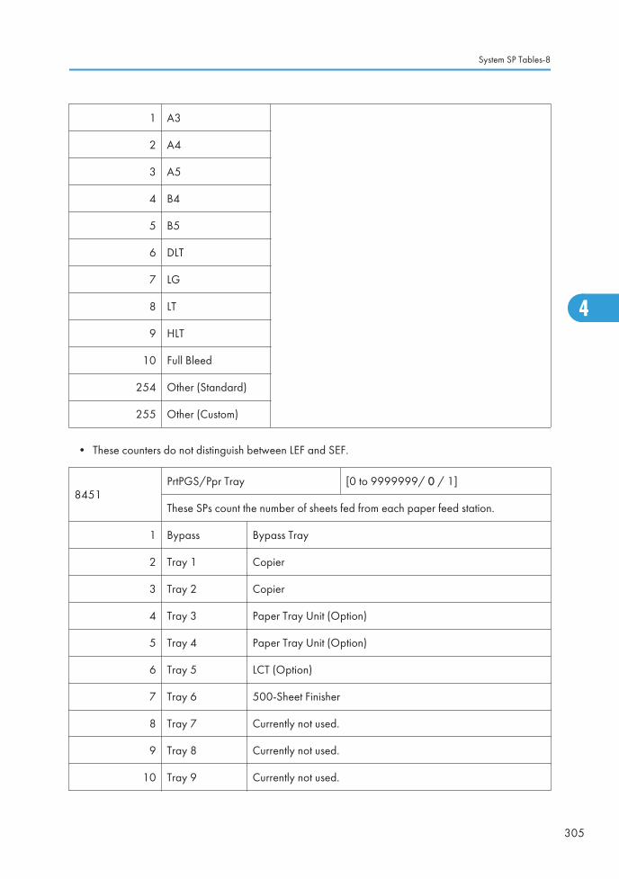
1 A3
2 A4
3 A5
4 B4
5 B5
6 DLT
7 LG
8 LT
9 HLT
10 Full Bleed
254 Other (Standard)
255 Other (Custom)
• These counters do not distinguish between LEF and SEF.
8451PrtPGS/Ppr Tray [0 to 9999999/ 0 / 1]
These SPs count the number of sheets fed from each paper feed station.
1 Bypass Bypass Tray
2 Tray 1 Copier
3 Tray 2 Copier
4 Tray 3 Paper Tray Unit (Option)
5 Tray 4 Paper Tray Unit (Option)
6 Tray 5 LCT (Option)
7 Tray 6 500-Sheet Finisher
8 Tray 7 Currently not used.
9 Tray 8 Currently not used.
10 Tray 9 Currently not used.
System SP Tables-8
305
4

11 Tray 10 Currently not used.
12 Tray 11 Currently not used.
13 Tray 12 Currently not used.
14 Tray 13 Currently not used.
15 Tray 14 Currently not used.
16 Tray 15 Currently not used.
8461
T:PrtPGS/Ppr Type [0 to 9999999/ 0 / 1]
These SPs count by paper type the number pages printed by all applications.
• These counters are not the same as the PM counter. The PM counter is basedon feed timing to accurately measure the service life of the feed rollers.However, these counts are based on output timing.
• Blank sheets (covers, chapter covers, slip sheets) are also counted.
• During duplex printing, pages printed on both sides count as 1, and a pageprinted on one side counts as 1.
8462C:PrtPGS/Ppr Type [0 to 9999999/ 0 / 1]
These SPs count by paper type the number pages printed by the copy application.
8463F:PrtPGS/Ppr Type [0 to 9999999/ 0 / 1]
These SPs count by paper type the number pages printed by the fax application.
8464
P:PrtPGS/Ppr Type [0 to 9999999/ 0 / 1]
These SPs count by paper type the number pages printed by the printerapplication.
8466
L:PrtPGS/Ppr Type [0 to 9999999/ 0 / 1]
These SPs count by paper type the number pages printed from within thedocument server mode window at the operation panel.
1 Normal
2 Recycled
3 Special
4 Thick
4. Appendix: Service Program Mode Tables
306
4

5 Normal (Back)
6 Thick (Back)
7 OHP
8 Other
8471PrtPGS/Mag [0 to 9999999/ 0 / 1]
These SPs count by magnification rate the number of pages printed.
1 to 49%
2 50% to 99%
3 100%
4 101% to 200%
5 201% to
• Counts are done for magnification adjusted for pages, not only on the operation panel butperformed remotely with an external network application capable of performing magnificationadjustment as well.
• Magnification adjustments done with printer drivers with PC applications such as Excel are alsocounted.
• Magnification adjustments done for adjustments after they have been stored on the documentserver are not counted.
• Magnification adjustments performed automatically during Auto Reduce/Enlarge copying arecounted.
• The magnification rates of blank cover sheets, slip sheets, etc. are automatically assigned a rate of100%.
8481 T:PrtPGS/TonSave
8484
P:PrtPGS/TonSave
These SPs count the number of pages printed with the Toner Save feature switchedon.
Note: These SPs return the same results because this SP is limited to the Printapplication.
[0 to 9999999/ 0 / 1]
System SP Tables-8
307
4

8511T:PrtPGS/Emul [0 to 9999999/ 0 / 1]
These SPs count by printer emulation mode the total number of pages printed.
8514P:PrtPGS/Emul [0 to 9999999/ 0 / 1]
These SPs count by printer emulation mode the total number of pages printed.
1 RPCS
2 RPDL
3 PS3
4 R98
5 R16
6 GL/GL2
7 R55
8 RTIFF
9 PDF
10 PCL5e/5c
11 PCL XL
12 IPDL-C
13 BM-Links Japan Only
14 Other
15 IPDS
• SP8511 and SP8514 return the same results because they are both limited to the Print application.
• Print jobs output to the document server are not counted.
8521
T:PrtPGS/FIN [0 to 9999999/ 0 / 1]
These SPs count by finishing mode the total number of pages printed by allapplications.
4. Appendix: Service Program Mode Tables
308
4

8522
C:PrtPGS/FIN [0 to 9999999/ 0 / 1]
These SPs count by finishing mode the total number of pages printed by the Copyapplication.
8523
F:PrtPGS/FIN [0 to 9999999/ 0 / 1]
These SPs count by finishing mode the total number of pages printed by the Faxapplication.
8524
P:PrtPGS/FIN [0 to 9999999/ 0 / 1]
These SPs count by finishing mode the total number of pages printed by the Printapplication.
8525
S:PrtPGS/FIN [0 to 9999999/ 0 / 1]
These SPs count by finishing mode the total number of pages printed by theScanner application.
8526
L:PrtPGS/FIN [0 to 9999999/ 0 / 1]
These SPs count by finishing mode the total number of pages printed from withinthe document server mode window at the operation panel.
Note:
• If stapling is selected for finishing and the stack is too large for stapling, theunstapled pages are still counted.
• The counts for staple finishing are based on output to the staple tray, so jamrecoveries are counted.
1 Sort
2 Stack
3 Staple
4 Booklet
5 Z-Fold
6 Punch
7 Other
8 Inside-Fold
9 Three-IN-Fold
System SP Tables-8
309
4

10 Three-OUT-Fold
11 Four-Fold
12 KANNON-Fold
13 Perfect-Bind
14 Ring-Bind
8531 Staples
This SP counts the amount of staples used by themachine.
[0 to 9999999/ 0 / 1]
8551 T: PrtBooks/FIN
8552 O: PrtBooks/FIN
8554 P: PrtBooks/FIN
8556 L: PrtBooks/FIN
1 Perfect-Bind Not Used
2 Ring-Bind Not Used
8581
T:Counter [0 to 9999999/ 0 / 1]
These SPs count the total output broken down by color output, regardless of theapplication used. In addition to being displayed in the SMC Report, thesecounters are also displayed in the User Tools display on the copy machine.
8591
O:Counter [0 to 9999999/ 0 / 1]
These SPs count the totals for A3/DLT paper use, number of duplex pagesprinted, and the number of staples used. These totals are for Other (O:)applications only.
1 A3/DLT
2 Duplex
4. Appendix: Service Program Mode Tables
310
4

8601
Coverage Counter [0 to 9999999/ 0 / 1]
These SPs count the total coverage for each color and the total printout pages foreach printing mode.
1 B/W
2 B/W Printing Pages
8617SDK Apli Counter [0 to 9999999/ 0 / 1]
These SPs count the total printout pages for each SDK applicaion.
1 SDK-1
2 SDK-2
3 SDK-3
4 SDK-4
5 SDK-5
6 SDK-6
8621 Func Use Counter DFU
1 to 64 Function 001 to Function 064
8631
T:FAX TX PGS [0 to 9999999/ 0 / 1]
These SPs count by color mode the number of pages sent by fax to a telephonenumber.
8633
F:FAX TX PGS [0 to 9999999/ 0 / 1]
These SPs count by color mode the number of pages sent by fax to a telephonenumber.
• If a document has color and black-and-white pages mixed, the pages are counted separately asB/W or Color.
• At the present time, this feature is provided for the Fax application only so SP8631 and SP8633are the same.
• The counts include error pages.
System SP Tables-8
311
4

• If a document is sent to more than one destination with a Group transmission, the count is done foreach destination.
• Polling transmissions are counted but polling RX are not.
• Relay, memory, and confidential mailbox transmissions and are counted for each destination.
8641
T:IFAX TX PGS [0 to 9999999/ 0 / 1]
These SPs count by color mode the number of pages sent by fax to as fax imagesusing I-Fax.
8643
F:IFAX TX PGS [0 to 9999999/ 0 / 1]
These SPs count by color mode the number of pages sent by Fax as fax imagesusing I-Fax.
• If a document has color and black-and-white pages mixed, the pages are counted separately asB/W or Color.
• At the present time, this feature is provided for the Fax application only so SP8641 and SP8643are the same.
• The counts include error pages.
• If a document is sent to more than one destination with a Group transmission, the count is done foreach destination.
• Polling transmissions are counted but polling RX are not.
• Relay, memory, and confidential mailbox transmissions and are counted for each destination.
8651
T:S-to-Email PGS [0 to 9999999/ 0 / 1]
These SPs count by color mode the total number of pages attached to an e-mailfor both the Scan and document server applications.
8655
S:S-to-Email PGS [0 to 9999999/ 0 / 1]
These SPs count by color mode the total number of pages attached to an e-mailfor the Scan application only.
1 B/W
2 Color
Note
• The count for B/W and Color pages is done after the document is stored on the HDD. If the job iscancelled before it is stored, the pages are not counted.
4. Appendix: Service Program Mode Tables
312
4

• If Scan-to-Email is used to send a 10-page document to 5 addresses, the count is 10 (the pagesare sent to the same SMTP server together).
• If Scan-to-PC is used to send a 10-page document to 5 folders, the count is 50 (the document issent to each destination of the SMB/FTP server).
• Due to restrictions on some devices, if Scan-to-Email is used to send a 10-page document to alarge number of destinations, the count may be divided and counted separately. For example, if a10-page document is sent to 200 addresses, the count is 10 for the first 100 destinations and thecount is also 10 for the second 100 destinations, for a total of 20.
8661
T:Deliv PGS/Svr [0 to 9999999/ 0 / 1]
These SPs count by color mode the total number of pages sent to a Scan Routerserver by both Scan and LS applications.
8665
S:Deliv PGS/Svr [0 to 9999999/ 0 / 1]
These SPs count by color mode the total number of pages sent to a Scan Routerserver by the Scan application.
1 B/W
2 Color
Note
• The B/W and Color counts are done after the document is stored on the HDD of the Scan Routerserver.
• If the job is canceled before storage on the Scan Router server finishes, the counts are not done.
• The count is executed even if regardless of confirmation of the arrival at the Scan Router server.
8671
T:Deliv PGS/PC [0 to 9999999/ 0 / 1]
These SPs count by color mode the total number of pages sent to a folder on a PC(Scan-to-PC) with the Scan and LS applications.
8675
S:Deliv PGS/PC [0 to 9999999/ 0 / 1]
These SPs count by color mode the total number of pages sent with Scan-to-PCwith the Scan application.
1 B/W
2 Color
System SP Tables-8
313
4

8681 T:PCFAX TXPGS These SPs count the number of pages sent by PC Fax.These SPs are provided for the Fax application only,so the counts for SP8681 and SP8683 are the same.
[0 to 9999999/ 0 / 1]8683 F:PCFAX TXPGS
• This counts pages sent from a PC using a PC fax application, from the PC through the copier to thedestination.
• When sending the same message to more than one place using broadcasting, the pages are onlycounted once. (For example, a 10-page fax is sent to location A and location B. The counter goesup by 10, not 20.)
8691 T:TX PGS/LS These SPs count the number of pages sent from thedocument server. The counter for the application that wasused to store the pages is incremented.
[0 to 9999999/ 0 / 1]
The L: counter counts the number of pages stored fromwithin the document server mode screen at the operationpanel. Pages stored with the Store File button from withinthe Copy mode screen go to the C: counter.
8692 C:TX PGS/LS
8693 F:TX PGS/LS
8694 P:TX PGS/LS
8695 S:TX PGS/LS
8696 L:TX PGS/LS
Note
• Print jobs done with Web Image Monitor and Desk Top Binder are added to the count.
• If several documents are merged for sending, the number of pages stored are counted for theapplication that stored them.
• When several documents are sent by a Fax broadcast, the F: count is done for the number ofpages sent to each destination.
8701
TX PGS/Port [0 to 9999999/ 0 / 1]
These SPs count the number of pages sent by the physical port used to send them.For example, if a 3-page original is sent to 4 destinations via ISDN G4, the countfor ISDN (G3, G4) is 12.
1 PSTN-1
2 PSTN-2
3 PSTN-3
4 ISDN (G3,G4)
4. Appendix: Service Program Mode Tables
314
4

5 Network
8711
T:Scan PGS/Comp [0 to 9999999/ 0 / 1]
These SPs count the number of compressed pages scanned into the documentserver, counted by the formats listed below.
1 JPEG/JPEG2000
2 TIFF (Multi/Single)
3 PDF
4 Other
5 PDF/Comp
8 715
S:Scan PGS/Comp [0 to 9999999/ 0 / 1]
These SPs count the number of compressed pages scanned by the scanapplication, counted by the formats listed below.
1 JPEG/JPEG2000
2 TIFF (Multi/Single)
3 PDF
4 Other
5 PDF/Comp
8721 T: Deliv PGS/WSD [0 to 9999999/ 0 / 1]
8725 S: Deliv PGS/WSD [0 to 9999999/ 0 / 1]
8731 T: Scan PGS/Media [0 to 9999999/ 0 / 1]
8735 S: Scan PGS/Media [0 to 9999999/ 0 / 1]
1 B/W
2 Color
System SP Tables-8
315
4

8741
RX PGS/Port [0 to 9999999/ 0 / 1]
These SPs count the number of pages received by the physical port used toreceive them.
1 PSTN-1
2 PSTN-2
3 PSTN-3
4 ISDN (G3,G4)
5 Network
8771
Dev Counter [0 to 9999999/ 0 / 1]
These SPs count the frequency of use (number of rotations of the developmentrollers) for black and other color toners.
8781
Toner_Bottl_Info. [0 to 9999999/ 0 / 1]
This SP displays the number of toner bottles used. The count is done based on theequivalent of 1,000 pages per bottle.
8791 LS Memory Remain
This SP displays the percent of space available on thedocument server for storing documents.
[0 to 100/ 0 / 1]
8801
Toner Remain [0 to 100/ 0 / 1]
This SP displays the percent of toner remaining for each color. This SP allows theuser to check the toner supply at any time.
Note
• This precise method of measuring remaining toner supply (1% steps) is betterthan other machines in the market that can only measure in increments of 10(10% steps).
• This SP is expanded for color MFP and color LP machines. For this machine,the count is done for black only.
4. Appendix: Service Program Mode Tables
316
4

8851Cvr Cnt: 0-10% [0 to 9999999/ 0 / 1]
These SPs count the number of pages for each coverage range.
11 0 to 2%:BK
21 3 to 4%:BK
31 5 to 7%:BK
41 8 to 10%:BK
8861Cvr Cnt: 11-20% [0 to 9999999/ 0 / 1]
These SPs count the percentage of dot coverage for black other color toners.
1 K Black toner
8871Cover Cnt: 21-30% [0 to 9999999/ 0 / 1]
These SPs count the percentage of dot coverage for black other color toners.
1 K Black toner
8881Cover Cnt: 31% - [0 to 9999999/ 0 / 1]
These SPs count the percentage of dot coverage for black other color toners.
1 K Black toner
8891 Page/Toner Bottle DFU
8901 Page/Toner_Prev1 DFU
8911 Page/Toner_Prev2 DFU
8921Cvr Cnt/Total [0 to 9999999/ 0 / 1]
Displays the total coverage and total printout number for each color.
1 Coverage (%): BK
11 Coverage / P: BK
System SP Tables-8
317
4

8941
Machine Status [0 to 9999999/ 0 / 1]
These SPs count the amount of time the machine spends in each operation mode.These SPs are useful for customers who need to investigate machine operation forimprovement in their compliance with ISO Standards.
1 Operation TimeEngine operation time. Does not include time whilecontroller is saving data to HDD (while engine is notoperating).
2 Standby TimeEngine not operating. Includes time while controllersaves data to HDD. Does not include time spent inEnergy Save, Low Power, or Off modes.
3 Energy Save TimeIncludes time while the machine is performingbackground printing.
4 Low Power TimeIncludes time in Energy Save mode with Engine on.Includes time while machine is performing backgroundprinting.
5 Off Mode TimeIncludes time while machine is performing backgroundprinting. Does not include time machine remainspowered off with the power switches.
6 SC Total down time due to SC errors.
7 PrtJam Total down time due to paper jams during printing.
8 OrgJam Total down time due to original jams during scanning.
9 Supply PM Wait End Total down time due to toner end.
8951
AddBook Register
These SPs count the number of events when the machine manages dataregistration.
4. Appendix: Service Program Mode Tables
318
4

1 User Code User code registrations.
[0 to 9999999/ 0 / 1]
2 Mail AddressMail addressregistrations.
3 Fax DestinationFax destinationregistrations.
4 GroupGroup destinationregistrations.
5 Transfer RequestFax relay destinationregistrations for relay TX.
6 F-Code F-Code box registrations.
7 Copy Program
Copy applicationregistrations with theProgram (job settings)feature.
[0 to 255 / 0 / 255]
8 Fax Program
Fax applicationregistrations with theProgram (job settings)feature.
9 Printer Program
Printer applicationregistrations with theProgram (job settings)feature.
10 Scanner Program
Scanner applicationregistrations with theProgram (job settings)feature.
8999Admin. Counter List [0 to 9999999/ 0 / 1]
Displays the total coverage and total printout number for each color.
1 Total
3 Copy: BW
7 Printer: BW
System SP Tables-8
319
4

10 Fax Print: BW
12 A3/DLT
13 Duplex
15 Coverage: BW (%)
17 Coverage: BW Print Page
101 Transmission Total: Color
102 Transmission Total: BW
103 FAX Transmission
104 Scanner Transmission: Color
105 Scanner Transmission: BW
4. Appendix: Service Program Mode Tables
320
4