riding the reflected wave-igbt drive technology demands
TRANSCRIPT
RIDING THE REFLECTED WAVE - IGBT DRIVE TECHNOLOGY DEMANDS NEW MOTOR AND CABLE CONSIDERATIONS
Copyright Material IEEE Paper No. PCIC-96-09
Lawrence A. Saunders Member IEEE Allen Bradley Company Allen Bradley Company 2615 Edenbom Ave., A Metairie. LA 70002
Gary L. Skibinski
6400 W. Enterprise Dr. Mequon, WI 53092
Abstract: Drive manufacturer migration to Insulated Gate Bipolar Transistor (IGBT) output devices demands a more careful selection of motors and load cables. IGBT drives have faster output voltage risetimes which have increased the dielectric voltage stress placed on the motor. Semiconductor risetime now has a greater influence on motor transient voltages, emphasizing the need to understand the reflected wave phenomenon and its system effects on both motors and cables. Issues and solutions relative to motor selection, cable selection and installation are outlined and discussed. Potential problems and solutions not commonly known, even among experienced drive users, are presented.
I. Introduction
Effective application of Variable Frequency Drives (VFD) normally requires a detailed understanding of VFD operation, motor performance, load characteristics, and of the potential application and installation issues. Migration to IGBT output devices has introduced some new issues relative to motor selection, load cabling and installation.
Inverter duty rated motor specifications historically addressed the thermal issues of drive related harmonic heating and insufficient cooling at low speeds. Different motor manufacturer's interpret "inverter duty" to mean different things. It may not connote any motor ability to handle the increased reflected wave voltage stress resulting from IGBT drive application. Reflected wave voltage amplitude is a function of cable length and voltage risetime. It was generally held that cable distances less than 100 ft. did not experience motor problems. This paper will dispel this myth. A range of possible drive solutions are presented to assist the application engineer. The scope of this paper is limited to installations not exceeding 600 VAC or 600 hp applications.
A . Wh-v Have P WM Drives Become Popular ?
Pulse Width Modulated (PWM) drive technology has become the most popular drive technology due to the many advantages:
High-efticiency (97% to 98%)
Low sensitivity to line transients
Constant high input power factor
Multi-motor application capability
Operation
Minimum power line notching
6 Hz possible w/o cogging
Small relative size
Ride-through capability
Open-circuit protection
Common bus regeneration
- Wide speed range
Excellent speed regulation
Steve T. Evon Reliance Electric Chevron USA Offshore 10 1 Reliance Road Kings Mountain, NC 28086
David L. Kempkes
935 Gravier Street N e w Orleans, L A 701 12
Early designs used Gate Turn-off thyristors (GTO) and Bipolar Junction Transistors (BJT) as butput devices. However, there has been a migration to IGBT output devices.
B. Wh-v the Migration to IGBT Output Devices ?
BJT and GTO devices have current controlled gates. The current controlled gate circuits are somewhat complex. IGBTs have voltage controlled gates. The voltage controlled gate circuits are simpler and faster. IGRTs interface more easily with drive low voltage control circuitry.
VFD using IGBTs can operate at higher carrier or switching frequencies due to IGBT fast switching risetimes. IGBT drives produce rated torque with lower peak current than BJT drives and have smaller heat sinks. Smaller heat sinks allow smaller drives, smaller drives result in lower packaging costs. Higher carrier frequencies also reduce motor lamination noise in the audible range, not uncommon in BJT or GTO based drives.
The combination of simpler, faster control circuits and higher carrier frequencies allow higher performance drives with high starting torque and especially good performance at low speeds (below 10 Hz). Supply of IGBT devices is growing, thereby maintaining some control on IGBT costs. BJT and GTO semiconductors are in shorter supply. Therefore, IGBTs with ratings to 1200A are becoming relatively less expensive.
11. The Reflected Wave Phenomenon
A. WhatIs It ?
The inverter section of a PWM drive does not produce sinusoidal output voltage wave forms but generates a continuous train of pulses as in Fig. la.
These voltage pulses are "transmitted" to the motor terminals via the motor cable. Peak pulse voltage at the drive output is equal to the drive DC bus magnitude ( Vbus ) and contains steep fronted rise and fall times (t,ise, tf.11 ) controlled by the GTO, BJT or IGBT semiconductor switching device used in the drive. Peak pulse voltage at the motor terminals is not necessarily Vbzrs but is dependent upon the dynamics of the drive-cable-motor circuit defined by drive output voltage risetime, cable transmission line characteristics, cable length, and motor impedance to the pulse voltage. Fig. Ib shows the pulse train at the motor terminals has momentary transient over-voltages at every switch point, up to twice the Vbus pulse voltage from the drive, These over-voltages may produce potentially destructive voltage stress on the motor insulation.
ISBN: 0-7803-3587-2 96-CH35988-6/96/0000-0075 $05.00 8 1996 IEEE
- 75 -

I I
. . : . . , . . . . , . . . .
Fig. la. (Top) PWM Voltage At Drive Output
Fig. lb. (Bottom) PWM Voltage At Motor Terminals
This over-voltage phenomenon is sometimes known as "Transmission Line Effect", "Reflected Wave" or "Standing Wave" [l-41. Fig. 2 details a single voltage pulse arriving at the motor terminals, creating an unterminated reflected voltage wave of 1260 Vpeak or 1.95 pu from a 480V IGBT drive with a Vbus = 650 Vdc. Per unit (pu) is defined in this paper aspu = Peak line-lineVmotor / VbUs. Reflected Wave transients occur at every drive switching instant defined by the drive carrier frequency. Reflected wave transients are independent of drive fundamental output frequency. It is important to realize that up to 2 pu reflected wave voltage phenomenon is possible on all AC motors at some cable length regardless of the type of output switching device employed by the drive.
Dealing with the phenomenon effectively requires an understanding o f the variables that determine peak reflected wave magnitude, a methodology to estimate maximum motor voltage for a given cable length, and a motor time-voltage dielectric withstand ability curve to coordinate reflected wave peak magnitude and risetime under repetitive pulse operation.
I I I I I 1 I I n I 1
1000
5 600 Y
0 5 10 15 20 25 30 Time (p)
Fig. 2. Motor Reflected Wave Pulse Amplitude [5 ps/div:200v/div] (A) Unterminated, (B) Reactor at Drive, (C) Terminator Network
B. What Causes It ?
Reflected wave at the motor terminals may be explained using well- documented cable transmission line theory [5,6]. The magnitude of the sending end PWM voltage pulse at the drive is Vbus. The magnitude of receiving end reflected wave voltage at the motor ( 1 ) depends on a voltage ring-up factor r where 0 < r 2 1.0. It is defined in (2) as "Refection Coeficient" and is a function of cable surge impedance (Z,) and load surge impedance (Zload ) presented at the receiving end of the cable.
Reflection Coefficient: r = qoad - zO qoad +zO -~
Cable Surge Impedance. zo= & ( 3 )
The cable presents a definitive measurable surge impedance Zo to the traveling wave sent and is defined in ( 3 ) as inductance ( L ) per unit length divided by capacitance (C)per unit length of cable. Although cable L-C parameters vary with wire gauge and cable construction, it was found that Z, is relatively constant, between 80 to I80 Q, for 3 wires in a conduit, 4 wire tray cable and armor cable in sizes from # I 8 AWG to 500 MCM [7].
Induction motor load surge impedance Zload to traveling waves with fast rising edges is not well documented, not easily measured, nor well understood since it requires a new high frequency induction motor equivalent circuit that is dominated by stray winding parameters. Experimental results show motors < 5 hp have a surge impedance of 2,000-5,000 C2, a 125 hp motor has a Zloqd around 800 R, while a 500 hp motor has a load surge impedance in the vicinity of 400 R.
Whenever the cable surge impedance does not match the surge impedance of the motor, a reflected wave will occur at the motor terminals. Substitution of Zload and Z, into (2) yields r E 0.95 for motors < 5 hp, z 0.82 for 125 hp motors and r z 0.6 for 500 hp motors. Theoretical peak reflected wave over-voltage for single cable runs from ( 1 ) is thus 1.95 pu for low hp motors, 1.85 pu for medium hp and 1.6 pu for high hp motors. However, high hp drives often parallel cables, thus reducing Zo, increasing to 0.9, and increasing theoretical motor over-voltage back to 1.9 pu.
C. Variables AJfecting Reflected Wave Magnitude
Factors affecting motor over-voltage are [7 ] :
Motor & cable surge impedance i Magnitude of drive pulse
Motor load Risetime o f drive pulse
Cable length Spacing of PWM pulses
Motor and cable surge impedance mismatch are primarily responsible for the magnitude of peak pu over-voltage.
The risetime of the drive pulse primarily determines a critical cable distance I,. where peak pu over-voltage is developed. Cable lengths < IC will develop correspondingly less pu over-voltage than those determined by (1). Cable lengths > I , will develop at least the pu
- 76 -
over-voltages determined by (1) and possibly greater values, dependent on the spacing of PWM pulses [SI. Critical cable length is calculated using standing wave analysis. The drive pulse risetime is controlled by the switching device risetime. Risetime (trise ) is converted to an equivalent sinewave frequenc and wavelen th (A)
Equating I , to the quarter wavelength distance h/4, where peak standing waves of 2 pu are developed and substituting (4) into ( 5 ) yields the critical cable distance IC where peak over-voltage occurs
in meters, where c = speed of light = 3x10 2 m/s (934x10 5 ft/s).
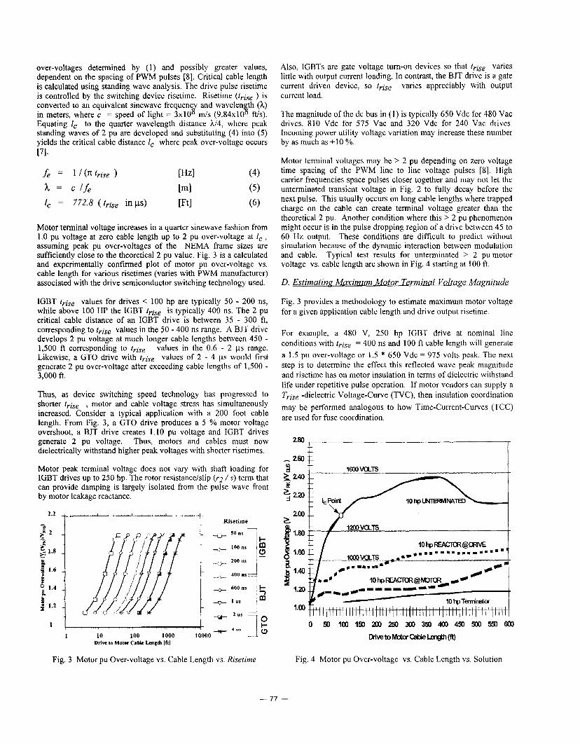
Motor terminal voltage increases in a quarter sinewave fashion from 1.0 pu voltage at zero cable length up to 2 pu over-voltage at I , , assuming peak pu over-voltages of the NEMA frame sizes are suficiently close to the theoretical 2 pu value. Fig. 3 is a calculated and experimentally confirmed plot of motor pu over-voltage vs. cable length for various risetimes (varies with PWM manufacturer) associated with the drive semiconductor switching technology used.
IGBT trise values for drives < 100 hp are typically 50 - 200 ns, while above 100 HP the IGBT trise is typically 400 ns. The 2 pu critical cable distance of an IGBT drive is between 35 - 300 ft, corresponding to trise values in the 50 - 400 ns range. A BJT drive develops 2 pu voltage at much longer cable lengths between 450 - 1,500 ft corresponding to rrise values in the 0.6 - 2 bs range. Likewise, a GTO drive with trise values of 2 - 4 ps would first generate 2 pu over-voltage after exceeding cable lengths of 1,500 - 3,000 ft.
Thus, as device switching speed technology has progressed to shorter trise , motor and cable voltage stress has simultaneously increased. Consider a typical application with a 200 foot cable length. From Fig. 3, a GTO drive produces a 5 % motor voltage overshoot, a BJT drive creates 1.10 pu voltage and IGBT drives generate 2 pu voltage. Thus, motors and cables must now dielectrically withstand higher peak voltages with shorter risetimes.
Motor peak terminal voltage does not vary with shaft loading for IGBT drives up to 250 hp. The rotor resistance/slip ('2 /s) term that can provide damping is largely isolated from the pulse wave front by motor leakage reactance.
Risetime -
400 ns ---I
1 I . . 1 10 100 1000 $000 -
Drive IO Motor Cable Lmzth If11
Also, IGBTs are gate voltage tum-on devices so that trise, varies little with output current loading. In contrast, the BJT drive is a gate current driven device, so t,ise varies appreciably with output current load.
The magnitude of the dc bus in (1) is typically 650 Vdc for 480 Vac drives, 810 Vdc for 575 Vac and 320 Vdc for 240 Vac drives. Incoming power utility voltage variation may increase these number by as much as + I O YO.
Motor terminal voltages may be > 2 pu depending on zero voltage time spacing of the PWM line to line voltage pulses [SI. High carrier frequencies space pulses closer together and may not let the unterminated transient voltage in Fig. 2 to fully decay before the next pulse. This usually occurs on long cable lengths where trapped charge on the cable can create terminal voltage greater than the theoretical 2 pu. Another condition where this > 2 pu phenomenon might occur is in the pulse dropping region of a drive between 45 to 60 Hz output. These conditions are difficult to predict without simulation because of the dynamic interaction between modulation and cable. Typical test results for unterminated > 2 pu motor voltage vs. cable length are shown in Fig. 4 starting at 100 ft.
D. Estimating Maximum Motor Terminal Voltage Magnitude
Fig. 3 provides a methodology to estimate maximum motor voltage for a given application cable length and drive output risetime.
For example, a 480 V, 250 hp IGBT drive at nominal line conditions with t,ise = 400 ns and 100 ft cable length will generate a 1.5 pu over-voltage or 1.5 * 650 Vdc = 975 volts peak. The next step is to determine the effect this reflected wave peak magnitude and risetime has on motor insulation in terms of dielectric withstand life under repetitive pulse operation. If motor vendors can supply a Trise -dielectric Voltage-Curve (TVC), then insulation coordination may be performed analogous to how Time-Current-Curves (TCC) are used for fuse coordination.
200 z
1.00 I , ,
I I i i i i i j i i i i i i i i i I i-1 I I I 1 1 I I hi I 1 I I I I I ,
Fig. 3 Motor pu Over-voltage vs. Cable Length vs. Risetime Fig. 4 Motor pu Over-voltage vs. Cable Length vs. Solution
- 77 -

E. Effect of Reflected Wave on 600 V Induction Motors
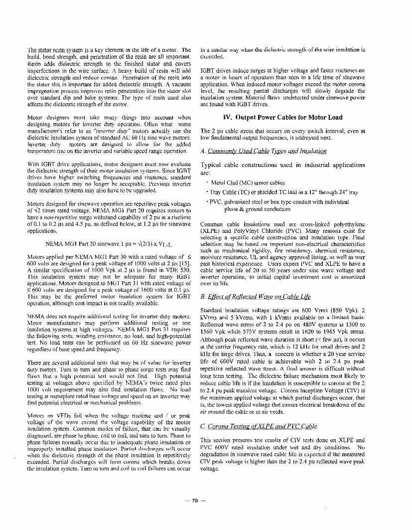
Most standard motors manufactured today have insulation designed to dielectrically withstand a specific window of "surge I' voltages that are commonly seen on the AC power lines. Fig. 5 shows a machine impulse voltage withstand envelope for both 480V and 575V operation, which gives the minimum expected machine insulation strength over the life of the machine as documented by a 1981 IEEE Working Group report [9-1 I ] and tested per NEMA MG 1 Part 20.
Of importance is the higher withstand voltage for longer risetime of the wavefront surge. times > 6 IJS is ultimately determined by the breakdown strength of the magnet wire. Slow rising edges have a volts per turn gradient on the motor coik approaching that of the 60 Hz sine wave operation. The lower withstand voltage for shorter risetime is a result of a nonlinear voltage gradient on the motor coils creating a higher than design voltiturn stress on the insulation which may result in breakdown, corona or partial discharges. IEC has published a similiar dielectric withstand curve for motors having breakpoints of 1000 Volts peak at 100 ns and 1300 Vpk at 1 ps.
The peak level for tvlse
Fig. 5 also shows estimated dielectric withstand voltage vs. risetime capability for various motor vendors. Risetimes 2 ps show reduced magnitudes as compared to the IEEE curves due to the concern over partial discharges occurring ,at high carrier frequencies causing additional heating and insulation degradation.
Motor vendor capability for IGBT trLse < 0.4 ps is greater than indicated in the IEEE study showing typical values of 1000 V at 100 ns and 1150 V at 100 ns as two common groupings. Motors without phase-phase and slot liner insulation typically fall into the 1000 Vpk category while those with additional insulation in the standard motor tend to fall into the < 1200 Vpk category. Fig. 5 shows that a 480V BJT drive having trise = 2 ~s and 2 pu application voltage (1300 Vpk) is within standard motor capability and is field experience proven to have few failures while a 480 V IGBT drive having trise =lo0 ns and 2 pu (1300 Vpk) application voltage will exceed, on paper, most motor manufacturer's dielectric capability and has shown to have a small percentage of field failures with some motor vendors.
3500 f /r 3000 IEEE 5 7 5 ~ ' /IEEE 48ov
2500
*ooo // ~ Brand NEMA MG I Part 31
1500
0 i i i i ~ i i i i ; 1 +I I H ~ i i i i i i i 1 i i 0.00 0.50 1.00 1.50 2.00 2.50 3.00 3.50 4.00 4.50 5.00 5.50 6.00
Risetime (ps)
Fig. 5 . Motor Dielectric Withstand Envelope vs. Surge Risetime
Thus, the new technology has changed dielectric stress on the motor and cable into a previously unspecified and untested region. Research is underway with motor manufacturers to determine tests quantifying motor dielectric capability in the i: 1 ps region at rated temperature [ 12,131. Meanwhile, motor manufacturers are redesigning to meet the latest National Electric Manufacturer's Association (NEMA) Specification MG I-part 3 I .40.4.2 which specifies voltage spike insulation capability required as 1600 Vpk at 100 ns for new "Inverter Rated" motor designs [14]. This motor, as it becomes available, would be a preferred choice for 480 V and 575 V IGBT drive systems having 2 pu reflected wave motor voltages of 1300 Vpk and 1600 Vpk respectively.
111. Insulation Systems of AC Induction Motors
Motor insulation systems may vary between motor manufacturers. Insulation systems may vary depending on voltage and horsepower of the motor. Primary insulation components in a random wound AC induction motor are stator wire insulation, phase and group paper, slot insulation, and the stator resin system.
The type and quality of the stator wire insulation is crucial to the life the motor on inverter power. The stator wire is subjected to elongation and abuse during the winding process. It is imperative that the stator wire insulation have both good dielectric strength and resistance to abuse. The wire film is the primary insulation between turns and often between coils in a phase group. Polyester film coated wire is common for most machine wound NEMA frame size motors. Larger motors with inverter duty insulation sometimes use a higher surge wire. This wire may include a Dacron glass and added film thickness over polyester film. Dacron glass coating improves the wire's dielectric strength as well as its resistance to abuse. Since these motors are usually hand wound, glass coating can be used. Film coated wire is normally required for machine wound stators.
Placement of phase and group paper in a stator is important for motors operated on variable speed drives. Phase paper is necessary for all induction motors, excluding some fractional horsepower motors (where it is excluded for cost purposes). Group paper is usually used only on larger motors.
Phase paper is necessary for motors used on IGBT drives due to the steep wave fronts, high switching frequencies and increased voltage due to the "neutral shift" effect. The phase paper separates the phases where the highest voltage differential in a winding occurs. Motors on IGBT drives require higher dielectric strength phase paper than motors on sinewave power. The steeper wave fronts of the IGBT also make the correct placement of the phase paper imperative.
Within a coil group, the highest voltage stress occurs between the turns in the first coil or the first two coils in a phase group. Location of group paper within a phase group varies depending on motor manufacturer. When used, it is usually placed at least between the first two coils. In smaller mQtors, group insulation is often difficult to install between coils and may not be used.
Slot insulation in the stator is the primary ground insulation in the random wound motor. Slot insulation is normally adequate to withstand the steep wave front of the IGBT drive. In some cases longer slot cell and topstick lengths may be required for IGBT drive applications due to increased voltages.
- 70 -
The stator resin system is a key element in the life of a motor. The build, bond strength, and penetration of the resin are all important. Resin adds dielectric strength to the finished stator and covers imperfections in the wire surface. A heavy build of resin will add dielectric strength and reduce corona. Penetration of the resin into the stator slot is important for added dielectric strength. A vacuum impregnation process improves resin penetration into the stator slot over standard dip and bake systems. The type of resin used also affects the dielectric strength of the motor.
Motor designers must take many things into account when designing motors for inverter duty operation. Often what some manufacturer’s refer to as “inverter duty” motors actually use the dielectric insulation system of standard AC 60 Hz sine wave motors. Inverter duty motors are designed to allow for the added temperature rise on the inverter and variable speed range operation.
With IGBT drive applications, motor designers must now evaluate the dielectric strength of their motor insulation systems. Since IGBT drives have higher switching frequencies and risetimes, standard insulation system may no longer be acceptable. Previous inverter duty insulation systems may also have to be upgraded.
Motors designed for sinewave operation see repetitive peak voltages of 42 times rated voltage. NEMA MGl Part 20 requires motors to have a non-repetitive surge withstand capability of 2 pu at a risetime of 0.1 to 0.2 ys and 4.5 pu, as defined below, at 1.2 ys for sinewave applications.
NEMA MGI Part 20 sinewave 1 pu = d(2/3) x VL-L
Motors applied per NEMA MG1 Part 30 with a rated voltage of i 600 volts are designed for a peak voltage of 1000 volts at 2 ps [Is]. A similar specification of 1000 Vpk at 2 ps is found in VDE 530. This insulation system may not be adequate for many IGBT applications. Motors designed to MG 1 Part 3 1 with rated voltage of I 600 volts are designed for a peak voltage of 1600 volts at 0.1 ps. This may be the preferred motor insulation system for IGBT operation, although cost impact is not readily available.
NEMA does not require additional testing for inverter duty motors. Motor manufacturers may perform additional testing or test insulation systems at high voltages. NEMA MGl Part 31 requires the following tests: winding resistance, no load, and high-potential test. No load tests can be performed on 60 Hz sinewave power regardless of base speed and frequency.
There are several additional tests that may be of value for inverter duty motors. Turn to turn and phase to phase surge tests may find flaws that a high potential test would not find. High potential testing at voltages above specified by NEMA’S twice rated plus 1000 volt requirement may also find insulation flaws. No load testing at nameplate rated base voltage and speed on an inverter may find potential electrical or mechanical problems.
Motors on VFDs fail when the voltage risetime and / or peak voltage of the wave exceed the voltage capability of the motor insulation system. Common modes of failure, that can be visually diagnosed, are phase to phase, coil to coil, and turn to turn. Phase to phase failures normally occur due to inadequate phase insulation or improperly installed phase insulation. Partial discharges will occur when the dielectric strength of the phase insulation is repetitively exceeded. Partial discharges will form corona which breaks down the insulation system. Turn to turn and coil to coil failures can occur
in a similar way when the dielectric strength of the wire insulation is exceeded.
IGBT drives induce surges at higher voltage and faster risetimes on a motor in hours of operation than seen in a life time of sinewave application. When induced motor voltages exceed the motor corona level, the resulting partial discharges will slowly degrade the insulation system. Material flaws undetected under sinewave power are found with IGBT drives.
IV. Output Power Cables for Motor Load
The 2 pu cable stress that occurs on every switch interval, even at low fundamental output frequencies, is addressed next.
A.
Typical cable constructions used in industrial applications are :
* Metal Clad (MC) armor cables ’ Tray Cable (TC) or shielded TC laid in a 12” through 24” tray
- PVC, galvanized steel or box type conduit with individual phase & ground conductors
Common cable insulations used are cross-linked polyethylene (XLPE) and Polyvinyl Chloride (PVC). Many reasons exist for selecting a specific cable construction and insulation type. Final selection may be based on important non-electrical characteristics such as mechanical rigidity, fire retardency, chemical resistance, moisture resistance, UL and agency approval listing, as well as user past historical experience. Users expect PVC and XLPE to have a cable service life of 20 to 50 years under sine wave voltage and inverter operation, so initial capital investment cost is amortized over its life.
B. Effect qf Reflected Wave on Cable Life
Standard insulation voltage ratings are 600 Vrms (850 Vpk), 2 kVrms and 5 kVrms, with 1 kVrms available on a limited basis. Reflected wave stress of 2 to 2.4 pu on 480V systems is 1300 to 1560 Vpk while 575V systems result in 1620 to 1945 Vpk stress. Although peak reflected wave duration is short (< few ys), it occurs at the carrier frequency rate, which is 12 kHz for small drives and 2 kHz for large drives. Thus, a concern is whether a 20 year service life of 600V rated cable is achievable with 2 to 2.4 pu peak repetitive reflected wave stress. A final answer is difficult without long term testing. The dielectric failure mechanism most likely to reduce cable life is if the insulation is susceptible to corona at the 2 to 2.4 pu peak transient voltage. Corona Inception Voltage (CIV) is the minimum applied voltage at which partial discharges occur, that is, the lowest applied voltage that causes electrical breakdown of the air around the cable or in air voids.
C. Corona Testing ofXLPE and PVC Cable
This section presents test results of CIV tests done on XLPE and PVC 600V rated insulation under wet and dry conditions. No degradation in sinewave rated cable life is expected if the measured CIV peak voltage is higher than the 2 to 2.4 pu reflected wave peak voltage.
- 79 -

Table 1. 60 Hz Sinewave Dielectric Test Voltage Specified in UL 1569 600 V Type MC vs.
Corona Inception Voltage Test Results @ 25 "C
30 10 30 3 4,242 4,942 15% 20 7.5-20 12 thru 14 30 3 15 0.5-5 12 thru 14 30 3 15
Table I contains 60 Hz Sinewave rms dielectric test voltages specified in UL 1569 Type MC 600V cable using both XLPE and PVC insulation as wire AWG is increased. A corona tester measured the CIV level between bundled wire samples for XLPE and PVC. Results show XLPE peak CIV under dry atmospheric conditions is within 5 %to 17 % of UL 1569 specified dielectric potentials, while tested PVC peak CIV is within 4 YO to 27% of UL specified peak voltages, if one neglects the 40 mil data point. Minimum tested CIV values of 2,723 Vpk for PVC and 4,942 Vpk for XLPE are greater than applied peak reflected wave voltage of 1,924 Vpk (575V system) so both 600V rated insulations should achieve rated life. Table I also shows XLPE cables have a higher CIV compared to PVC cables with the same insulation thickness. The higher CIV with XLPE insulated cables is probably due to XLPE's lower dielectric constant (2.3 vs. 5 for PVC) which results in a lower stress on the outside surface of the insulation.
CIV tests were done on 600V rated insulation, 30 mil XLPE and 15 mil THHN PVC, under wet conditions of 90% relative humidity for 48 hours. Results show XLPE CIV decreased only 5 YO afterwards while PVC had 50 % reduction in CIV. The PVC CIV increased to the dry CIV levels as the wire surfaces were dried off. Thus, 600 V XLPE will retain higher CIV levels than PVC in the presence of moisture. There is concern for 15 mil thickness PVC wire used in moisture laden applications and which contain nicks in the insulation induced by the wire pulling process. This combination may drop the dry 2,723 Vpk PVC 15 mil wire CIV level by 50 YO to 1361 Vpk and into the peak reflected wave voltage range of 1300- 1560 Vpk and 1620-1945 Vpk that occur in 480V and 575V applications, respectively. PVC thicknesses of 30 mils or greater are not of concern because of higher initial CIV levels tested in Table I. Thus, all 600 V rated XLPE and 600 V PVC cables 2 30 mils are adequate to handle the 2 pu reflected wave transient, while 15 mil PVC cables should be kept dry.
D. XLPE & PVC Cable Life with Reflected Wave Solutions
Reactors at the drive, output filters and terminator networks will beneficially reduce the reflected wave amplitude seen on the cable, increase cable life and eliminate wire voltage concerns, even for I 5
Specified CIV Voltage Test
(~VRMS) (Vpd (Vpd A = CIV - UL 3.0 4,242 4,793 12% 3.0
2.0 2,828 4,063 43% 2.5 3,535 4,450 25%
2.0 2,828 3,613 27% I l l 8%
2.0 12,82812,7231 -4%
mil PVC wire. Terminators limit peak applied cable voltage to less than the 850 Vpk sinewave rating, insuring cable service life similar to sinewave operation.
V. Solutions to Reflected Wave Problem
There are four ways of dealing with reflected voltage spikes: change system voltage to 240 Vac, specify 1600 Vpk motors, shorten output lead lengths or limit voltage peaks with external drive filters.
A. Selection qf Svstem Voltage
A 240 Vac IGBT drive with Vbus of 300 Vdc can use even existing standard 1000 Vpk insulated "inverfer rated" motors since 2 pu is only 600 Vpk at 100 ns, well below motor vendor dielectric withstand curves in Fig. 5.
B. qnecification qf Motor Insulation
Systems using 480 V and 575 V IGBT drive systems will have 2 pu reflected wave motor voltages of 1300 and 1600 Vpk at 100 ns risetime and should use 1600 Volt insulation (or higher). Specification of "Znverfer Rated" motors to NEMA MG 1 part 3 1 is the preferred solution. This motor insures unlimited cable lengths on 480 V systems without adding external motor protection mechanisms.
C. Limitation qf Motor Cable Lead Length
Limiting the motor cable distance is an effective method to protect the motor. Fig. 3 shows the amplitude of the reflected wave on the motor terminals is proportional to length of the motor cables up to the critical cable distance. If possible, the installation should be planned to minimize motor cable length. Guidelines for maximum cable lengths that maintain line to line reflected wave terminal voltage below that of existing 1200 Vpk and 1000 Vpk motors for a 480 Vac drive system are shown in Table 11. Conservative cable lengths are determined from horizontal line intersection of 1.5 pu (1000 Vpk) and 1.85 pu (1200 Vpk) magnitudes with the semiconductor risetime.
- 80 -
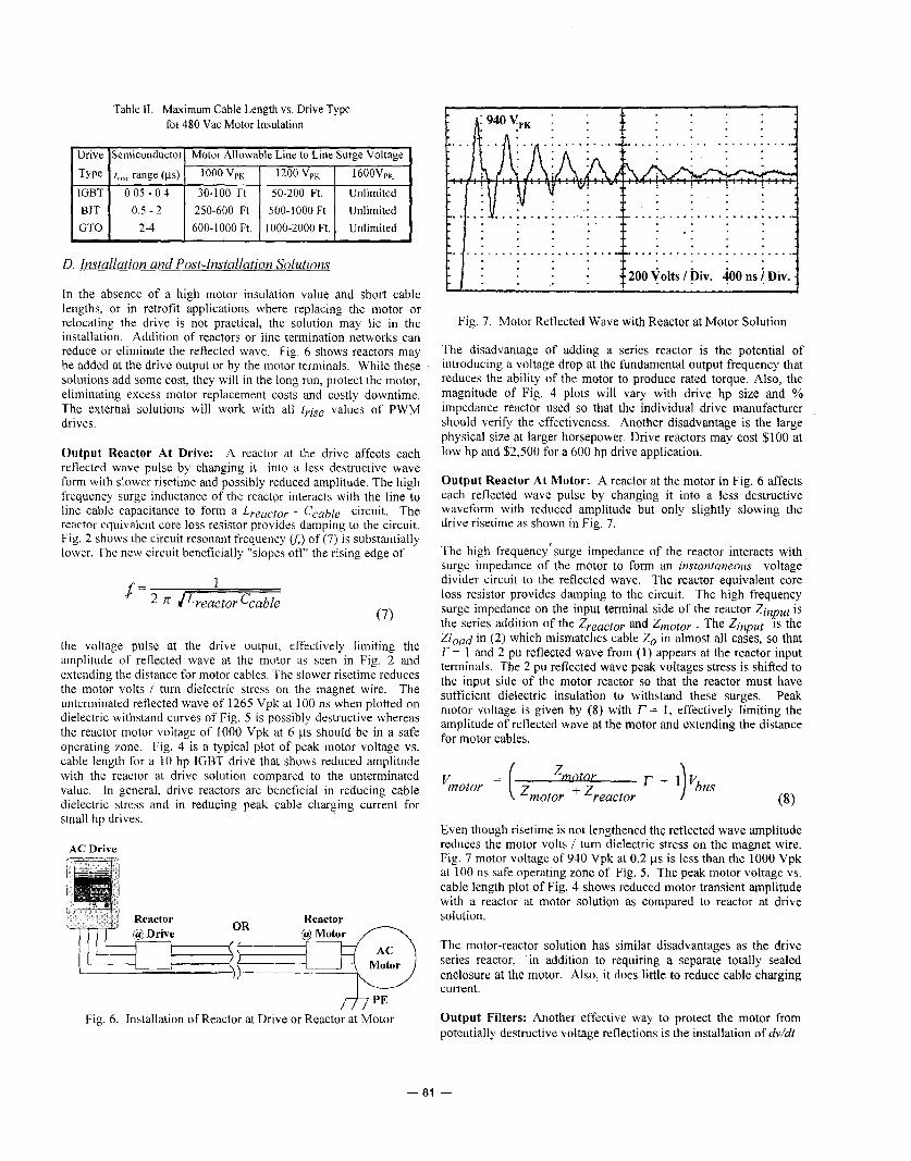
Table I1 Maximum Cable Length vs. Drive Type fot. 480 Vac Motor Insulation
D. Installation and Post-Installation Solutions
In the absence of a high motor insulation value and short cable lengths, or in retrofit applications where replacing the motor or relocating the drive is not practical, the solution may lie in the installation. Addition of reactors or line termination networks can reduce or eliminate the reflected wave. Fig. 6 shows reactors may be added at the drive output or by the motor terminals. While these solutions add some cost, they will in the long run, protect the motor, eliminating excess motor replacement costs and costly downtime. The external solutions will work with all tyise values of PWM drives.
Output Reactor At Drive: A reactor at the drive affects each reflected wave pulse by changing it into a less destructive wave form with slower risetime and possibly reduced amplitude. The high frequency surge inductance of the reactpr interacts with the line to line cable capacitance to form a Lreactor - Ccable circuit. The reactor equivalent core loss resistor provides damping to the circuit. Fig. 2 shows the circuit resonant frequency G) of (7) is substantially lower. The new circuit beneficially "slopes off' the rising edge of
1
(7)
the voltage pulse at the drive output, effectively limiting the amplitude of reflected wave at the motor as seen in Fig. 2 and extending the distance for motor cables. The slower risetime reduces the motor volts / turn dielectric stress on the magnet wire. The unterminated reflected wave of 1265 Vpk at 100 ns when plotted on dielectric withstand curves of Fig. 5 is possibly destructive whereas the reactor motor voltage of 1000 Vpk at 6 ps should be in a safe operating zone. Fig. 4 is a typical plot of peak motor voltage vs. cable length for a 10 hp IGBT drive that shows reduced amplitude with the reactor at drive solution compared to the unterminated value. In general, drive reactors are beneficial in reducing cable dielectric stress and in reducing peak cable charging current for small hp drives.
AC Drive
/f/ PE Fig. 6. Installation of Reactor at Drive or Reactor at Motor
[ i 9 4 0 V , , : f : n . : f :
, I . . * y . . . . . ............. . . . . . . . . '...............
/-J.+.-.! _...! . . . . !;..I Fig. 7. Motor Reflected Wave with Reactor at Motor Solution
The disadvantage of adding a series reactor is the potential of introducing a voltage drop at the fundamental output frequency that reduces the ability of the motor to produce rated torque. Also, the magnitude of Fig. 4 plots will vary with drive hp size and % impedance reactor used so that the individual drive manufacturer should verify the effectiveness. Another disadvantage is the large physical size at larger horsepower. Drive reactors may cost $100 at low hp and $2,500 for a 600 hp drive application.
Output Reactor At Motor: A reactor at the motor in Fig. 6 affects each reflected wave pulse by changing it into a less destructive waveform with reduced amplitude but only slightly slowing the drive risetime as shown in Fig. 7.
The high frequency 'surge impedance of the reactor interacts with surge impedance of the motor to form an instantaneous voltage divider circuit to the reflected wave. The reactor equivalent core loss resistor provides damping to the circuit. The high frequency surge impedance on the input terminal side of the reactor Zinput is the series addition of the Zreactoy and Zmotor . The Zinput IS the Zload in (2) which mismatches cable Zo in almost all cases, so that r= 1 and 2 pu reflected wave from (1) appears at the reactor input terminals. The 2 pu reflected wave peak voltages stress is shifted to the input side of the motor reactor so that the reactor must have sufficient dielectric insulation to withstand these surges. Peak motor voltage is given by (8) with r = 1, effectively limiting the amplitude of reflected wave at the motor and extending the distance for motor cables.
Zmotoy Vmotor = ( 'motor ''reactor l- + 1)VbUS
Even though risetime is not lengthened the reflected wave amplitude reduces the motor volts / turn dielectric stress on the magnet wire. Fig. 7 motor voltage of 940 Vpk at 0.2 ps is less than the 1000 Vpk at 100 ns safe operating zone of Fig. 5. The peak motor voltage vs. cable length plot of Fig. 4 shows reduced motor transient amplitude with a reactor at motor solution as compared to reactor at drive solution.
The motor-reactor solution has similar disadvantages as the drive series reactor, in addition to requiring a separate totally sealed enclosure at the motor. Also, it does little to reduce cable charging current.
Output Filters: Another effective way to protect the motor from potentially destructive voltage reflections is the installation of chi/&
- 81 -
7 1
6 : t ' J l
1 . 8 Stator Neutral to Gnd 1PU=4OOV Offset 4 I -+ Motor Line to Line 1PCI=400 V Offset 2
E> Inverter Line to tine 1PU=4WV
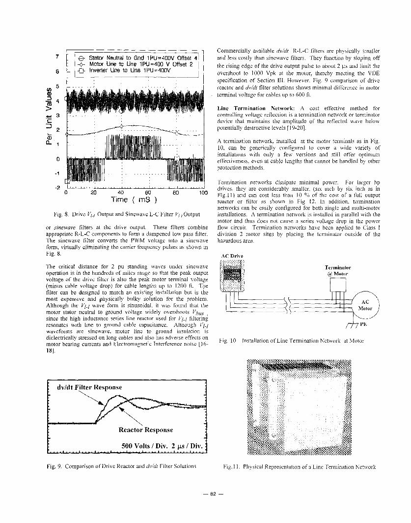
Fig. 8. Drive VI-/ Output and Sinewave L-C Filter V/.,Output
or sinewave filters at the drive output. These filters combine appropriate R-L-C components to form a dampened low pass filter. The sinewave filter converts the PWM voltage into a sinewave form, virtually eliminating the carrier frequency pulses as shown in Fig. 8.
The critical distance for 2 pu standing waves under sinewave operation is in the hundreds of miles range so that the peak output voltage of the drive filter is also the peak motor terminal voltage (minus cable voltage drop) for cable lengths up to 1200 ft. The filter can be designed to match an existing installation but is the most expensive and physically bulky solution for the problem. Although the V ~ J wave form is sinusoidal, it was found that the motor stator neutral to ground voltage widely overshoots Vbbls , since the high inductance series line reactor used for 111-1 filtering resonates with line to ground cable capacitance. Although V.i waveforms are sinewave, motor line to ground insulation is dielectrically stressed on long cables and also has adverse effects on motor bearing currents and Electromagnetic Interference noise [ 16- 181.
dvldt F9ter Response 1
b.
500 Volts I Div. 2 ps I Div. I . . . . l . . . . l . . . . I . . . . I . . . . 1 . . . . I . . . . l . . . . I . . . .
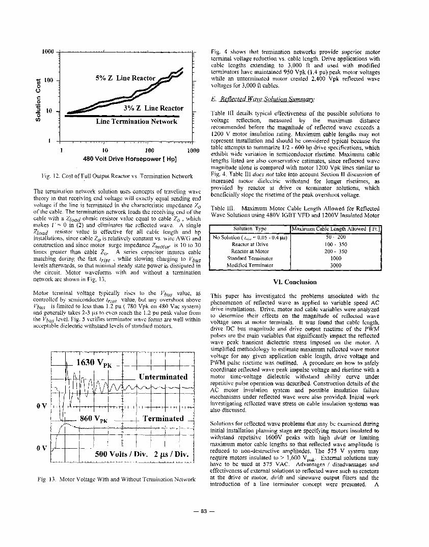
Commercially available dv/dt R-L-C filters are physically smaller and less costly than sinewave filters. They function by sloping off the rising edge of the drive output pulse to about 2 ps and limit the overshoot to 1000 Vpk at the motor, thereby meeting the VDE specification of Section 111. However, Fig. 9 comparison of drive reactor and dv/dt filter solutions shows minimal difference in motor terminal voltage for cables up to 600 ft.
Line Termination Network: A cost effective method for controlling voltage reflection is a termination network or terminator device that maintains the amplitude of the reflected wave below potentially destructive levels [ 19-20].
A termination network, installed at the motor terminals as in Fig. 10, can be generically configured to cover a wide variety of installations with only a few versions and still offer optimum effectiveness, even at cable lengths that cannot be handled by other protection methods.
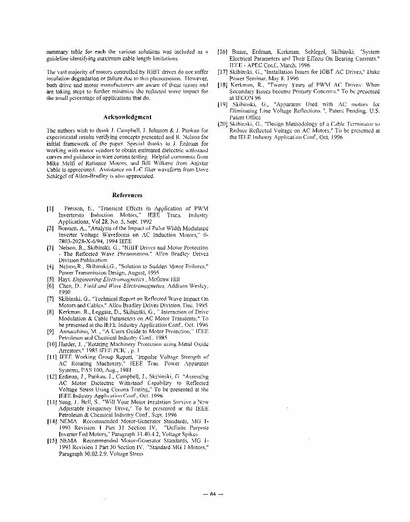
Termination networks dissipate minimal power. For larger hp drives, they are considerably smaller, (six inch by six inch as in Fig. 11) and can cost less than 10 YO of the cost of a full output reactor or filter as shown in Fig 12. In addition, termination networks can be easily configured for both single and multi-motor installations. A termination network is installed in parallel with the motor and thus does not cause a series voltage drop in the power flow circuit. Termination networks have been applied to Class I division 2 motor sites by placing the terminator outside of the hazardous area.
AC Drive
Terminator (9 Motor
r--i Motor -<-p
Fig. 10. Installation of Line Termination Network at Motor
Fig. 9. Comparison of Drive Reactor and dddt Filter Solutions Fig. 1 1 . Physical Representation of a Line Termination Network
- 82 -
loo0 c
500 Volts / Div. 2 ps / Div. ! . , , I , , , I ,>a I , , I ,
j; 100 7
0 0 C 0 .- c I 10 1 0 v)
5% Z Line React
Line Termination Network t
10 100 1000 480 Volt Drive Horsepower [ Hp]
Fig. 12. Cost of Full Output Reactor vs. Termination Network
The termination network solution uses concepts of traveling wave theory in that receiving end voltage will exactly equal sending end voltage if the line is terminated in the characteristic impedance Z, of the cable. The termination network loads the receiving end of the cable with a Zload ohmic resistor value equal to cable Zo , which makes r = 0 in (2) and eliminates the reflected wave. A single Zload resistor value is effective for all cable length and hp installations, since cable Z,, is relatively constant vs. wire AWG and construction and since motor surge impedance Zmoto, is 10 to 30 times greater than cable Z,,. A series capacitor insures cable matching during the fast t,jse , while slowing charging to Vbus levels afterwards, so that minimal steady state power is dissipated in the circuit. Motor waveforms with and without a termination network arc shown in Fig. 13.
Motor terminal voltage typically rises to the Vbus value, as controlled by semiconductor t,ise value, but any overshoot above Vbus is limited to less than 1.2 pu ( 780 Vpk on 480 Vac system) and generally takes 2-3 ps to even reach the 1.2 pu peak value from the Vbus level. Fig. 5 verifies terminator wave forms are well within acceptable dielectric withstand levels of standard motors.
ov
Fig. 13. Motor Voltage With and Without Termination Network
Fig. 4 shows that termination networks provide superior motor terminal voltage reduction vs. cable length. Drive applications with cable lengths extending to 3,000 fi and used with modified terminators have maintained 950 Vpk (1.4 pu) peak motor voltages while an unterminated motor created 2,400 Vpk reflected wave voltages for 3,000 ft cables.
E. Reflected Wave Solution Summaw
Table 111 details typical effectiveness of the possible solutions to voltage reflection, measured by the maximum distance recommended before the magnitude of reflected wave exceeds a 1200 V motor insulation rating. Maximum cable lengths may not represent installation and should be considered typical because the table attempts to summarize 1/2 - 600 hp drive specifications, which exhibit wide variation in semiconductor risetime. Maximum cable lengths listed are also conservative estimates, since reflected wave magnitude alone is compared with motor 1200 Vpk lines similar to Fig. 4. Table 111 does not take into account Section I1 discussion of increased motor dielectric withstand for longer risetimes, as provided by reactor at drive or terminator solutions, which beneficially slope the risetime of the peak overshoot voltage.
Table 111. Maximum Motor Cable Length Allowed for Reflected Wave Solutions using 480V IGBT VFD and 1200V Insulated Motor
Maximum Cable Length Allowed [ Ft.] 50- 200
Reactor at Drive 100- 350 Reactor at Motor 200- 350
Solution Type No Solution ( f,,,, = 0.05 - 0.4 ps)
Standard Terminator Modified Terminator
VI. Conclusion
This paper has investigated the problems associated with the phenomenon of reflected wave as applied to variable speed AC drive installations. Drive, motor and cable variables were analyzed to determine their effects on the magnitude of reflected wave voltage seen at motor terminals. It was found that cable length, drive DC bus magnitude and drive output risetime of the PWM pulses are the main variables that significantly impact the reflected wave peak transient dielectric stress imposed on the motor. A simplified methodology to estimate maximum reflected wave motor voltage for any given application cable length, drive voltage and PWM pulse risetime was outlined. A procedure on how to safely coordinate reflected wave peak impulse voltage and risetime with a motor time-voltage dielectric withstand ability curve under repetitive pulse operation was described. Construction details of the AC motor insulation system and possible insulation failure mechanisms under reflected wave were also provided. Initial work investigating reflected wave stress on cable insulation systems was also discussed.
Solutions for reflected wave problems that may be examined during initial installation planning stage are specifying motors insulated to withstand repetitive 1600V peaks with high dv/dt or limiting maximum motor cable lengths so that reflected wave amplitude is reduced to non-destructive amplitudes. The 575 V system may require motors insulated to 1,600 Vpeak. Extemal solutions may have to be used at 575 VAC. Advantages 1 disadvantages and effectiveness of extemal solutions to reflected wave such as reactors at the drive or motor, dv/dt and sinewave output filters and the introduction of a line terminator concept were presented. A
- 83 -
summary table for each the various solutions was included as a guideline identifying maximum cable length limitations.
The vast majority of motors controlled by IGBT drives do not suffer insulation degradation or failure due to this phenomenon. However, both drive and motor manufacturers are aware of these issues and are taking steps to further minimize the reflected wave impact for the small percentage of applications that do.
Acknowledgment
The authors wish to thank J. Campbell, J. Johnson & J. Pankau for experimental results verifying concepts presented and R. Nelson for initial framework of the paper. Special thanks to J. Erdman for working with motor vendors to obtain estimated dielectric withstand curves and guidance in wire corona testing. Helpful comments from Mike Melfi of Reliance Motors, and Bill Wilkens from Anixter Cable is appreciated. Assistance on L-C filter waveform from Dave Schlegel of Allen-Bradley is also appreciated.
References
[ I ] Person, E., "Transient Effects in Application of PWM Invertersto Induction Motors," IEEE Trans. Industry Applications, Vol28, No. 5 , Sept. 1992
[2] Bonnett, A., "Analysis of the Impact of Pulse Width Modulated Inverter Voltage Waveforms on AC Induction Motors," 0-
[3] Nelson, R., Skibinski, G., "IGBT Drives and Motor Protection - The Reflected Wave Phenomenon," Allen Bradley Drives Division Publication
[4] Nelson,R., Skibinski,G., "Solution to Sudden Motor Failures," Power Transmission Design, August, 1995
[5] Hayt, Engineering Electromagnetics , McGraw Hill [6] Chen, D., Field and Wave Electromagnetics, Addison Wesley,
1990 [7] Skibinski, G., "Technical Report on Reflected Wave Impact On
Motors and Cables," Allen Bradley Drives Division, Dec. 1995 [8] Kerkman, R., Leggate, D., Skibinski, G., " Interaction of Drive
Modulation & Cable Parameters on AC Motor Transients," To be presented at the IEEE Industry Application Conf., Oct. 1996
[9] Annacchino, M. , "A Users Guide to Motor Protection," IEEE Petroleum and Chemical Industry Conf., 1985
[lo] Harder, J. ,"Rotating Machinery Protection using Metal Oxide Arrestors," 1985 IEEE PClC , p. 1
[ I 1 1 IEEE Working Group Report, "Impulse Voltage Strength of AC Rotating Machinery," IEEE Tran. Power Apparatus Systems, PAS 100, Aug., 1981
[12] Erdman, J., Pankau, J., Campbell, J., Skibinski, G. "Assessing AC Motor Dielectric Withstand Capability to Reflected Voltage Stress Using Corona Testing," To be presented at the IEEE Industry Application C o d , Oct. 1996
1131 Sung, J., Bell, S., "Will Your Motor Insulation Survive a New Adjustable Frequency Drive," To be presented at the IEEE Petroleum & Chemical Industry Conf., Sept. 1996
[ 141 NEMA Recommended Motor-Generator Standards, MG 1 - 1993 Revision 1 Part 31 Section IV, "Definite Purpose Inverter Fed Motors," Paragraph 3 1.40.4.2, Voltage Spikes
[IS] NEMA Recommended Motor-Generator Standards, MG 1- 1993 Revision 1 Part 30 Section IV, "Standard MG 1 Motors," Paragraph 30.02.2.9, Voltage Stress
7803-2028-X-6/94, 1994 IEEE
[ 161 Busse, Erdman, Kerkman, Schlegel, Skibinski, "System Electrical Parameters and Their Effects On Bearing Currents," IEEE - APEC Conf., March, 1996
[I71 Skibinski, G., "Installation Issues for IGBT AC Drives,'' Duke Power Seminar, May 8, 1996
[I81 Kerkman, R., "Twenty Years of PWM AC Drives: When Secondary Issues become Primary Concerns," To be presented at IECON 96
[19] Skibinski, G., "Apparatus Used with AC motors for Eliminating Line Voltage Reflections ", Patent Pending, U.S. Patent Office
[20] Skibinski, G., "Design Methodology of a Cable Terminator to Reduce Reflected Voltage on AC Motors," To be presented at the IEEE Industry Application Conf., Oct. 1996
- a4 -

本文献由“学霸图书馆-文献云下载”收集自网络,仅供学习交流使用。
学霸图书馆(www.xuebalib.com)是一个“整合众多图书馆数据库资源,
提供一站式文献检索和下载服务”的24 小时在线不限IP
图书馆。
图书馆致力于便利、促进学习与科研,提供最强文献下载服务。
图书馆导航:
图书馆首页 文献云下载 图书馆入口 外文数据库大全 疑难文献辅助工具