rigging handbook for trail work · 2 introduction a safe day on the trail begins before you arrive...
TRANSCRIPT

RIGGING HANDBOOK For Trail Work
New York-New Jersey Trail Conference
1
Table of Contents Introduction .................................................................................................................................................................... 2
1. General Worksite Safety Responsibilities ............................................................................................................ 2
Field Safety Officer Responsibilities: ....................................................................................................................... 2
2. Rules for Rigging ...................................................................................................................................................... 3
OSHA RIGGING RULES: ........................................................................................................................................ 3
RIGGING RULES BEYOND OSHA: ...................................................................................................................... 4
Four Rigging Maxims to Remember: ........................................................................................................................ 5
3. SWL-Safe Working Loads ....................................................................................................................................... 5
4. Safe and Acceptable Rigging Arrangement- SAARA ...................................................................................... 6
SAARA- SWL .......................................................................................................................................................... 6
SAARA-Alignment ................................................................................................................................................ 7
SAARA-Anchor to Spar Angles ......................................................................................................................... 8
SAARA-Anchor to Spar Angles ......................................................................................................................... 8
5. Load Balance ............................................................................................................................................................. 8
6. Load Attachment ..................................................................................................................................................... 10
7. Load Slings ................................................................................................................................................................. 11
8. Anchor attachment ................................................................................................................................................. 12
9. Belaying ..................................................................................................................................................................... 13
Knots ....................................................................................................................................................................... 14
10. Port-A-Wrap ............................................................................................................................................................ 17
11. Call and Response ................................................................................................................................................... 17
12. Equipment Maintenance ....................................................................................................................................... 17
Equipment Retirement ............................................................................................................................................... 18
13. Alternate set-ups .................................................................................................................................................... 19
14. Dragging ................................................................................................................................................................... 19
15. Mechanical Advantage ......................................................................................................................................... 20
16. Math to know ........................................................................................................................................................... 21

2
Introduction A safe day on the trail begins before you arrive for trail work, continues while traveling to the work site, during your tasks, and after you leave. Your safety, the safety of coworkers, and the safety of the public is your highest priority. It is your responsibility to work safely, be aware of your surroundings, the risks involved, and any unsafe situations should they arise. Rigging is a special part of trail building meant to bring efficiency, and environmental impact reduction to work sites. It is also an extremely dangerous activity. This document provides the groundwork for a safe day rigging on the trail working with the Trail Conference (TC). The following also applies when training, working, and staying at the Welch Education Center.
1. General Worksite Safety Responsibilities 1. Knowing
a. The responsibilities set forth in this document b. Emergency Response Plans c. Escape routes d. The location of first aid and sting kits e. Leave No Trace Principles (p.3 safety handbook) f. Environmental Protection Principles (p.3 safety handbook)
2. Identifying a. Unsafe conditions b. The presence of the general public passing into worksite
3. Reporting/announcing a. Unsafe conditions b. The presence of the general public passing into work site
4. Recording a. Job Hazard Analysis (JHA) reports b. Accidents c. Injuries d. All required information in all required safety documents (see safety handbook Appendix)
5. Maintaining and Inspecting a. Job site b. First aid kits c. Tools (hand tools, power tools, machinery, and rigging equipment) d. Personal Protective Equipment
Field Safety Officer Responsibilities: 1. Know Emergency Response Plan and take lead in an Emergency situation 2. Compliance with TC and host agency environmental, health, and safety policy

3
3. Lead Tailgate Safety Meetings 4. Coordinate compliance of the Environmental Protection Responsibilities (p.3) 5. Insure first aid kits are stocked and at the work site 6. Insure that Volunteer Information Forms are at the worksite 7. Be aware of special medical issues of volunteers and location of emergency medicine
(inhaler/epi pen, etc.)
2. Rules for Rigging A. OSHA safety guidelines (1926.251.xx) will be adhered to for:
1. ALL Grip Hoist winches 2. High lines, aka: Slack Line, Sky Line, Sky Wire
OSHA RIGGING RULES: 1. 1926.251(a)(1): Rigging equipment . . .shall be inspected prior to use on each shift and as
necessary during its use to ensure that it is safe. Defective rigging equipment shall be removed from service.
2. 1926.251(a)(2)(i): Has permanently affixed and legible identification markings. . . that indicate the recommended safe working load [SWL]
3. 1926.251(a)(2)(ii): Not be loaded in excess of its recommended [SWL] 4. 1926.251(a)(2)(iii): Not be used without affixed, legible identification markings, required by
paragraph (a)(2)(i) of this section 5. 1926.251(a)(3): Rigging equipment, when not in use, shall be removed from the immediate
work area so as not to present a hazard to employees 6. 1926.251(b)(3): Job or shop hooks and links, or makeshift fasteners, formed from bolts,
rods, etc., or other such attachments, shall not be used 7. 1926.251(c)(3): Wire rope shall not be secured by knots, except on scraper haul back lines 8. 1926.251(c)(6): Slings shall not be shortened with knots or bolts or other makeshift devices 9. 1926.251(c)(7): Sling legs shall not be kinked 10. 1926.251(c)(8): Slings in a basket hitch shall have the loads balanced to prevent slippage 11. 1926.251(c)(10): Hands or fingers shall not be placed between the sling and its load while
the sling is being tightened around the load 12. 1926.251(c)(11): Shock loading is prohibited 13. 1915.113(b)(2): Loads shall be applied to the throat of the hook since loading the point
overstresses and bends or springs the hook. 14. There are no OSHA regulations for gates over the throat of hooks, but NYNJTC REQUIRES
a gate be used, or a wire be fashioned to the hook to act as a gate a. In lieu of a hook without a gate, a shackle should be used instead b. OSHA gate interpretation: https://www.osha.gov/pls/oshaweb/owadisp.show_
document ?p_table=INTERPRETATIONS&p_id=25276 15. Setting spar blocks
a. 1917.119(c): Portable Metal Ladders must meet ANSI A14.2-1990 safety requirements b. Neither the ladder standard (29 CFR 1926, subpart X) nor the fall protection
standard (29 CFR 1926, subpart M) requires fall protection for workers while working on portable ladders (https://www.osha.gov/pls/oshaweb/owadisp.show_d ocument?p_table=INTERPRETATIONS&p_id=23870)
c. Nevertheless, when setting a spar higher than your height (pretty much any situation), climbers MUST use a fall arrest system
4
i. Under §1926.502(d)(16)(iii), a personal fall arrest system must limit an employee's free fall to not more than six feet.
ii. 1926.502(d)(9) Lanyards and vertical lifelines shall have a minimum breaking strength of 5,000 pounds
iii. 1926.502(d)(16)(ii) limit maximum arresting force on an employee to 1,800 pounds (8 kN) when used with a body harness;
iv. 1926.502(d)(16)(iii) be rigged such that an employee can neither free fall more than 6 feet (1.8 m), nor contact any lower level;
v. 1926.502(d)(16)(v) If the system is used by an employee having a combined tool and body weight of 310 pounds (140 kg) or more, then the employer must appropriately modify the criteria and protocols
d. Maintain full control while climbing or descending ladders i. ladder use must include both hands and feet 1926.1053(b)(22) ii. attach a hand-line to harness, then remove to use for raising/lowering sling
and block for spar set up
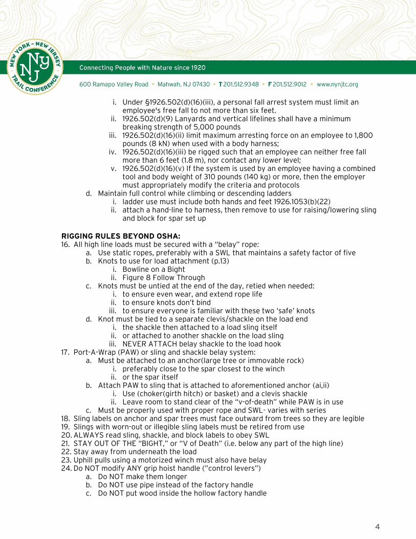
RIGGING RULES BEYOND OSHA: 16. All high line loads must be secured with a “belay” rope:
a. Use static ropes, preferably with a SWL that maintains a safety factor of five b. Knots to use for load attachment (p.13)
i. Bowline on a Bight ii. Figure 8 Follow Through
c. Knots must be untied at the end of the day, retied when needed: i. to ensure even wear, and extend rope life ii. to ensure knots don’t bind iii. to ensure everyone is familiar with these two ‘safe’ knots
d. Knot must be tied to a separate clevis/shackle on the load end i. the shackle then attached to a load sling itself ii. or attached to another shackle on the load sling iii. NEVER ATTACH belay shackle to the load hook
17. Port-A-Wrap (PAW) or sling and shackle belay system: a. Must be attached to an anchor(large tree or immovable rock)
i. preferably close to the spar closest to the winch ii. or the spar itself
b. Attach PAW to sling that is attached to aforementioned anchor (ai,ii) i. Use (choker(girth hitch) or basket) and a clevis shackle ii. Leave room to stand clear of the “v-of-death” while PAW is in use
c. Must be properly used with proper rope and SWL- varies with series 18. Sling labels on anchor and spar trees must face outward from trees so they are legible 19. Slings with worn-out or illegible sling labels must be retired from use 20. ALWAYS read sling, shackle, and block labels to obey SWL 21. STAY OUT OF THE “BIGHT,” or “V of Death” (i.e. below any part of the high line) 22. Stay away from underneath the load 23. Uphill pulls using a motorized winch must also have belay 24. Do NOT modify ANY grip hoist handle (”control levers”)
a. Do NOT make them longer b. Do NOT use pipe instead of the factory handle c. Do NOT put wood inside the hollow factory handle
5
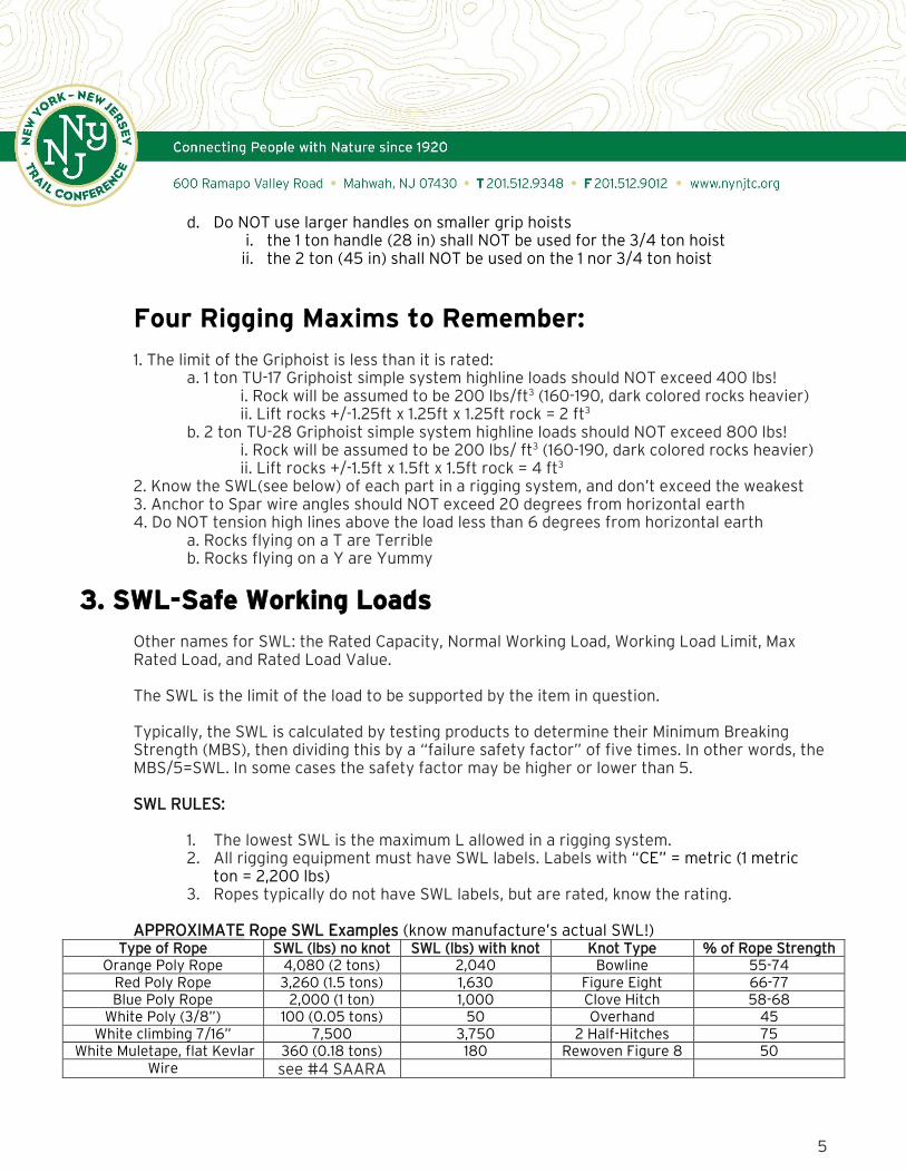
d. Do NOT use larger handles on smaller grip hoists i. the 1 ton handle (28 in) shall NOT be used for the 3/4 ton hoist ii. the 2 ton (45 in) shall NOT be used on the 1 nor 3/4 ton hoist
Four Rigging Maxims to Remember:
1. The limit of the Griphoist is less than it is rated: a. 1 ton TU-17 Griphoist simple system highline loads should NOT exceed 400 lbs!
i. Rock will be assumed to be 200 lbs/ft3 (160-190, dark colored rocks heavier) ii. Lift rocks +/-1.25ft x 1.25ft x 1.25ft rock = 2 ft3
b. 2 ton TU-28 Griphoist simple system highline loads should NOT exceed 800 lbs! i. Rock will be assumed to be 200 lbs/ ft3 (160-190, dark colored rocks heavier) ii. Lift rocks +/-1.5ft x 1.5ft x 1.5ft rock = 4 ft3
2. Know the SWL(see below) of each part in a rigging system, and don’t exceed the weakest 3. Anchor to Spar wire angles should NOT exceed 20 degrees from horizontal earth 4. Do NOT tension high lines above the load less than 6 degrees from horizontal earth
a. Rocks flying on a T are Terrible b. Rocks flying on a Y are Yummy
3. SWL-Safe Working Loads
Other names for SWL: the Rated Capacity, Normal Working Load, Working Load Limit, Max Rated Load, and Rated Load Value. The SWL is the limit of the load to be supported by the item in question. Typically, the SWL is calculated by testing products to determine their Minimum Breaking Strength (MBS), then dividing this by a “failure safety factor” of five times. In other words, the MBS/5=SWL. In some cases the safety factor may be higher or lower than 5.
SWL RULES:
1. The lowest SWL is the maximum L allowed in a rigging system. 2. All rigging equipment must have SWL labels. Labels with “CE” = metric (1 metric
ton = 2,200 lbs) 3. Ropes typically do not have SWL labels, but are rated, know the rating.
APPROXIMATE Rope SWL Examples (know manufacture’s actual SWL!)
Type of Rope SWL (lbs) no knot SWL (lbs) with knot Knot Type % of Rope Strength Orange Poly Rope 4,080 (2 tons) 2,040 Bowline 55-74
Red Poly Rope 3,260 (1.5 tons) 1,630 Figure Eight 66-77 Blue Poly Rope 2,000 (1 ton) 1,000 Clove Hitch 58-68
White Poly (3/8”) 100 (0.05 tons) 50 Overhand 45 White climbing 7/16” 7,500 3,750 2 Half-Hitches 75
White Muletape, flat Kevlar 360 (0.18 tons) 180 Rewoven Figure 8 50 Wire see #4 SAARA
6
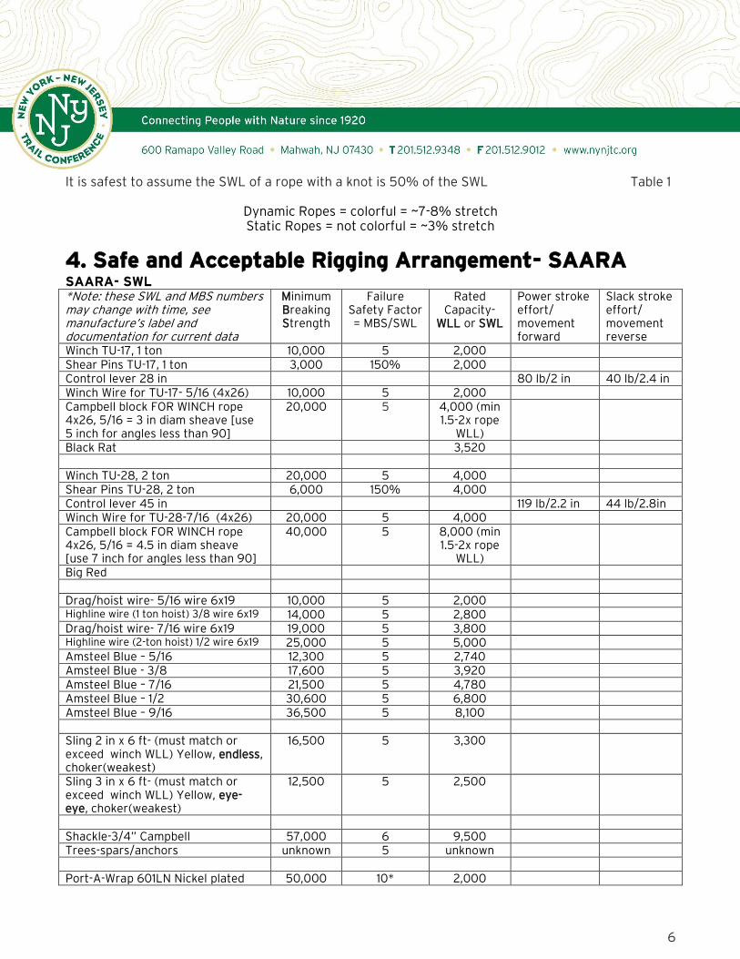
It is safest to assume the SWL of a rope with a knot is 50% of the SWL Table 1
Dynamic Ropes = colorful = ~7-8% stretch Static Ropes = not colorful = ~3% stretch
4. Safe and Acceptable Rigging Arrangement- SAARA SAARA- SWL *Note: these SWL and MBS numbers may change with time, see manufacture’s label and documentation for current data
Minimum Breaking Strength
Failure Safety Factor = MBS/SWL
Rated Capacity-
WLL or SWL
Power stroke effort/ movement forward
Slack stroke effort/ movement reverse
Winch TU-17, 1 ton 10,000 5 2,000 Shear Pins TU-17, 1 ton 3,000 150% 2,000 Control lever 28 in 80 lb/2 in 40 lb/2.4 in Winch Wire for TU-17- 5/16 (4x26) 10,000 5 2,000 Campbell block FOR WINCH rope 4x26, 5/16 = 3 in diam sheave [use 5 inch for angles less than 90]
20,000 5 4,000 (min 1.5-2x rope
WLL)
Black Rat 3,520 Winch TU-28, 2 ton 20,000 5 4,000 Shear Pins TU-28, 2 ton 6,000 150% 4,000 Control lever 45 in 119 lb/2.2 in 44 lb/2.8in Winch Wire for TU-28-7/16 (4x26) 20,000 5 4,000 Campbell block FOR WINCH rope 4x26, 5/16 = 4.5 in diam sheave [use 7 inch for angles less than 90]
40,000 5 8,000 (min 1.5-2x rope
WLL)
Big Red Drag/hoist wire- 5/16 wire 6x19 10,000 5 2,000 Highline wire (1 ton hoist) 3/8 wire 6x19 14,000 5 2,800 Drag/hoist wire- 7/16 wire 6x19 19,000 5 3,800 Highline wire (2-ton hoist) 1/2 wire 6x19 25,000 5 5,000 Amsteel Blue – 5/16 12,300 5 2,740 Amsteel Blue - 3/8 17,600 5 3,920 Amsteel Blue – 7/16 21,500 5 4,780 Amsteel Blue – 1/2 30,600 5 6,800 Amsteel Blue – 9/16 36,500 5 8,100 Sling 2 in x 6 ft- (must match or exceed winch WLL) Yellow, endless, choker(weakest)
16,500 5 3,300
Sling 3 in x 6 ft- (must match or exceed winch WLL) Yellow, eye-eye, choker(weakest)
12,500 5 2,500
Shackle-3/4” Campbell 57,000 6 9,500 Trees-spars/anchors unknown 5 unknown Port-A-Wrap 601LN Nickel plated 50,000 10* 2,000

7
steel (up to 3/4” rope) Sauerman for 3/8 wire 4,000 Sauerman for 1/2 wire 7,000 Sauerman for 5/8 wire 11,000
Table 2 Table 2 notes: MBS- Minimum Breaking Strength- usually 5xSWL, sometimes 4, 6, 10; 3 for DOT Rated Capacity, aka: working load limit (WLL), safe working load (SWL), normal working load (NWL), max rated load, rated
load value… Usually, not always, for wire, swl tons = rope diameter x rope diameter x 8 (5/16x5/16x8=200/256=0.78 tons. NOTE, this
is lower than the 1 ton rating of 5/16 wire for use with TU-17. The factory rope MBS is 10,000, making SWL 2,000) Use of Saurman Grip reduces SWL of wire rope by a factor of (see manufacture data) Use of U wire rope clips reduces SWL of wire rope by a factor of (see manufacture data) *10 is usually the Safety Factor for arboricultural rigging IMPORTANT: Sheave Block Diameter for angles less than 90 degrees = 16 times rope diameter for 4x26 (winch rope); 18-20 for 6x19 (common slack/high-line wire)…these are for vertical pulls where the lines are parallel, smaller blocks can be used for angles of 90 or more. For Amsteel Blue Rope = sheave block diameter must be 8 times the diameter of the line.
SAARA-Alignment
Fig 1

8
SAARA-Anchor to Spar Angles
Fig 2
SAARA-Anchor to Spar Angles
Fig 3
5. Load Balance
1. Ensure load is well wrapped and secure within sling(s). i. Any sign of slippage requires rapidly lowering the load and re-wrapping

9
2. Ensure load is balanced. i. Loads should be hung in a manner that puts the center of gravity (CG) DIRECTLY below
the load block hook (and beneath the lowest point of attachment) ii. Loads may shift when first lifted to swing CG under hook. If they hang in a manner that
causes the hook to tilt the load must be re-wrapped
Fig 4
Objects balance around their center of gravity, a point at which we can imagine all the object’s weight is centered or concentrated. Suspended objects will move so their center of gravity is below the point of support. Estimate CG location, lift the load with the hook over CG, then correct the estimate by moving the hook, load and sling suspension. In addition, support the load ABOVE the CG because it will move itself as low as possible below the point of support.
Fig 5

10
6. Load Attachment 1. When using shackles to lift loads ensure force is directed ONLY from bolt to crown. Side
loading reduces the SWL significantly.
Fig 6
2. ADD packing (washers) to ensure shackle does not shift.
Fig 7
Fig 8

11
3. ADD mousing (wire) to shackel pin if shifting is suppected to occur.
Fig 9,10
4. Do not surpass 120o on shackle, beyond this it is considered a side-load, and the SWL is reduced significantly.
Fig 11
5. To prevent opening up the hook and damage to rope eyes when two or more rope eyes, use a shackle (pin on hook (packed if needed), rope eyes to the shackle).
Fig 12
7. Load Slings Supporting 400-800 lb rocks will be tolerated by slings with a SWL of 2500 or more, meaning most slings and configurations. Slings can be cut by repeated dragging and wrapping. Capacities are based on nylon webbing having breaking strengths of 8000 pounds per inch of webbing width and Dacron (Polyester) having a

12
breaking strength of 5000 pounds per inch of webbing width. The capacities are also based on a 5:1 factor of safety, assuming that the end fittings are of adequate strength.
Table 3
8. Anchor attachment
Fig 13
Using a shackle can help reduce the wear on the sling from the wire rope

13
9. Belaying Belay lines are attached to loads to assure they travel a controlled path, and don’t run away.
Fig 14 Acceptable belay knots:
1. Figure eight a. Easy to check, hard to open b. Should be secured around the standing end using a stopper knot
i. Ashley Stopper ii. Double Overhand knot/stopper
c. Tie in "Flat" form, then tighten d. The two outermost turns are brought in snug against the ropes they enclose e. As a result these turns finish on the other side of the turns they accompany
2. Bowline on a bight a. Easy to check, easy to untie b. Loose unless actively loaded/pulled on c. Pass the tail outside the loop and under the collar to form a Yosemite Tie-off d. IMPORTANT: fasten the tail with a stopper knot to the adjoining loop or the
standing end i. Ashley Stopper

14
ii. Double Overhand knot/stopper
3. Terms: a. Bight: a bend or arc where ropes do not cross
i. Sometimes used to finish knots for easy untying ii. “knots on the bight” are tied without use of the working end
b. Dressing: arranging a knot to: i. improve performance, and/or strength ii. lower jamming/binding potential
c. Hitch: a knot to attach a rope to something, a shackle in our case d. Loop: a full circle passing the working end over itself e. Standing end (or standing part): not active in knot tying or opposite of the working
end f. Working end: (or working part) active in knot tying, opposite the standing end
Knots
Fig 15

15
Fig 16

16
Fig 17
Fig 18

17
10. Port-A-Wrap
Fig 19
11. Call and Response
Clear communication operating a high line system is mandatory to ensure those operating the system, and those working in the area, know what is taking place. Use walkie talkies and/or hand gestures to ensure clear communication between operators. Calls are made at a volume ‘everyone’ can hear, and repeated in response by others. TENSION or SLACK WINCH-REPEAT ROCK ON THE LINE or NO ROCK -REPEAT HOLD or SLACK BELAY- REPEAT
12. Equipment Maintenance It is important to keep equipment out of the dirt and as clean as possible to ensure a long life.
1. Wire Rope Clean with wire brushes and oil annually or as needed
2. Ropes and slings (including Amsteel Blue) Wash with clean water or non detergent soap (ivory) annually or as needed
3. Blocks Clean with wire brushes and grease sheaves annually or as needed
4. Griphoists Lubricate with gear oil every use Oil Bath monthly or as needed Full brake down and service annually or as needed

18
Equipment Retirement Retire any rigging equipment if it shows:
a. Wear below normal (wearing thin, decreasing in thickness or size) b. Degradation, including rust c. Cracks d. Missing Original Equipment or parts e. Signs of bending outside of factory design
Retire Fiber Rope: a. When sheath degradation is apparent b. The core is visible or coming through sheath c. The sheath is punctured or glazed from friction d. Consider retiring regularly used ropes after 5-10 years of use, unless “a” is a factor
Sling retirement: a. If you see red(fibers though the outer yellow or white), it’s dead b. If you can no longer read SWL label or label no longer exists
Wire retirement: a. If it no longer feeds through winch b. If thimbles are no longer in place or ends are compromised c. If any strands are broken or frayed
Fig 20

19
13. Alternate set-ups
1. Twin tramway- for heavy loads in need of two lines a. Set up parallel lines b. Use opposite side of spar trees c. Use alternate anchors if possible d. Two blocks/pulleys on the same load e. Two grip hoists operated in unison
2. Double-ended tramway- for long runs to make lifting load faster a. Two grip hoists b. At opposite anchors
3. Multi-stage tramway- for long or angled runs, with mid-air transfer a. First line is lower b. Second line is slacked to meet first lower line c. Load is transferred from first to second line
4. Motorized- for uphill transport a. Use a high quality and reliable brand b. Stay within the manufacture’s SWL tension rating and pulling capacity c. Consider erring on the side of safety by increasing the safety factor to 8 or more
14. Dragging
Fig 21 Dragging tricks and tips to reduce friction
Change sling bight on rock to spin rock rather than drag straight ahead Put the sling bight below the front of the rock for more frontal lift Put the sling bight in the rear of the rock to flip the rock Put the rock on a two rock bar railroad track NEVER drag a rock downhill or across a steep slope without a belay

20
15. Mechanical Advantage
Load/effort= mechanical advantage Questions to ask in determining the mechanical advantage of pulleys: 1. Number of supporting strand? = mechanical advantage 2. Tied off at anchor? = even # mechanical advantage 3. Tied off at load? = odd # mechanical advantage 4. Is the last pulley at the anchor fixed? Yes = a direction change with no advantage 5. # of anchor to load pulleys + 1? = mechanical advantage 6. Is the haul/pull line of a mech. adv. system being pulled by another mech. adv.? Yes = a
multiplier, i.e. a 4:1 tied to a 2:1 = 8:1 ^Questions answered for a one wire high line rigging setup (see image p.21): 1. Number of supporting strand? 2 2. Tied off at anchor? Yes, then even, 2:1 in this case 3. Tied off at load? No, not odd 4. Is the last pulley at the anchor fixed? yes = a direction change with no advantage 5. # of anchor to load pulleys + 1? 1 + 1 = 2 6. Is the haul/pull line of a mech. adv. system being pulled by another mech. adv.? no
The configurations in the image below can make lifting and/or dragging easier a. If done as shown, with nearly parallel arrangements, then the advantages will be as
shown, less any friction from the line/pulley. b. For example, 400 lbs becomes:
i. ~200 with 2:1 (400/2) ii. ~133 with 3:1 (400/3) iii. ~100 with 4:1 (400/4)
c. Advantage will still be gained with less than a parallel arrangement, for example, another nearby anchor at 10, 20, or 40 degrees away, but as degrees increase, advantage decrease
Fig 22

21
16. Math to know
It is not required to know the math involved in ensuring a rigging system does not exceed the rated capacity of any part of that system, but it helps to understand resultant forces and tensions as they relate to physical Laws, mainly Newton’s third law: or every reaction there is an equal, but opposite, reaction; or the sum of the forces up = the sum of the forces down; and sum of the forces right = the sum of the forces left
Fig 23
^side view of a typical highline arrangement, showing most of the relevant forces There is no belay line pictured, and the right spar (#2) is lower than spar #1, so the rock has drifted to the right. The line tension can be found by solving for T2 = W/(sinθ2+sinθ3) The use of pulleys means T1=T2=T3=T4 if the pulleys are nearly frictionless.
The use of a belay line and uneven spar block heights greatly compounds the difficulty of determining tensions. Contact Erik Mickelson ([email protected]) for a fully functional Excel spreadsheet of action/reaction tensions with belay lines and flat or sloped systems.

22
Fig 24
Single Basket Hitch
For vertical legs, SWL = SWL (of rope) X 2 For inclined legs, SWL = SWL (of rope) X H/L X 2
Double Basket Hitch
For vertical legs, SWL = SWL (of rope) X 4 For inclined legs, SWL = SWL (of rope) X H/L X 4
Fig 25

23
Double-Wrap Basket Hitch
Depending on the conjurations, the safe working loads are the same as for the single basket hitch or the double basket hitch.
Fig 26 Single Choker Hitch
For sling angles of 45° SWL = SWL (of rope) X 3/4 Sling angles of less than 45° are not recommended; however, if they must be used, the formula is: SWL = SWL (of rope) X A/B
Double Choker Hitch
For sling angles of 45° or more (formed by the choker), SWL = SWL (of rope) X 3/4 X H/L X 2. Sling angles of less than 45° (formed by the choker) are not recommended; however, if they must be used, the formula is: SWL = SWL (of rope) X A/B X H/L X 2.

24
Fig 27 Double-Wrap Choker Hitch
Depending on the configuration, the safe working loads are the same as for the single choker hitch or double choker hitch. Ensure that the sling angle is always greater than 45 degrees. To make sure that the angle is adequate once a load is rigged, check that the horizontal distance between the attachment points on the load is less than the length of the shortest sling leg. If this is the case, then the angle is greater than 60 degrees.
Fig 28
When using choker hitches, do not force the eye down toward the load once tension is applied; rope damage will result.