right angle crown® gear drives phone 800.533.1731 763.546.4300 fax 763.546.8260 2 ® m how to...
TRANSCRIPT

Right Angle Crown® Gear Drives

Features .......................................................................Benefits
Double sealed bearings .............................................Holds lubrication in, keeps dirt outPrecision hardened and ground ball bearings ..............Smooth, quiet, long operating lifeNon-magnetic stainless steel shafts ..............................Corrosion resistant. Minimal maintenanceAluminum alloy housing.............................................Light weight, high strength and heat dissipationMany standard types and sizes, plus special shafts.......Get the exact model that fits your application needsMultiple mounting positions ........................................Simplifies design considerationsProven design...........................................................Proven in thousands of applications for over 40 years
Crown two and three-way right angle gear drives transmitpower with quiet, dependable spiral bevel gears.
Crown right angle gear drives feature hardened spiral bevelgears and non-magnetic stainless steel shafts. They arecompact and feature multiple mounting options. The fullyenclosed design ensures that internal gears can’t get out ofalignment, jam up or become contaminated by debris.
The cast aluminum housing is designed for maximum strengthand heat dissipation.The drives are available with shafts of3/8, 1/2, 5/8 and 3/4 inch diameter in two and three-wayunits with both 1:1 and 2:1 ratios. Three-way units in 1:1and 2:1 ratios are available with 1 inch shafts. A widevariety of shafts are available including squared, splined,extended, shortened and stepped.
Applications include printing and packaging machines, off-highway vehicles and special machinery of all types.
1 www.zero-max.com Phone 800.533.1731 763.546.4300 Fax 763.546.8260
®
� �
HOW THE CROWN RIGHT ANGLE GEAR DRIVE WORKS

2www.zero-max.com Phone 800.533.1731 763.546.4300 Fax 763.546.8260
®
M � �
HOW TO SELECT A RIGHT ANGLE CROWN GEAR DRIVE1. Determine Your Preferred Input/Output Ratio. Standard ratios are 1:1 and 2:1. It is also possible to use a step up ratio of 1:2
by using shaft #2 as the input shaft. (See drawings on pages 3–5).
2. Designate Which Shafts Are To Be Input And Output Shafts. This step is especially important to determine that no shaft will turnfaster than 2000 RPM. If shaft #2 in the 2:1 ratio models is selected as the input shaft, it can turn at a maximum of 1000 RPM.In the 1:1 ratio models it makes no difference. However, the choice in either case will affect your mounting.
3. Be Certain That The Designated Output Shaft Has A Torque Capacity Greater Than Your Applications Load. Consult the tables onthe pages 6-8, and be sure to apply the service factors from the chart below.
4. Choose Drive Type. Use either 2-way or 3-way configuration.
5. Select The Correct Model Number. On pages 3–5, select the correct model number; note that units with 3/8 inch shafts haveflats and units with 1/2, 5/8, 3/4 and 1 inch shafts have standard keyways. Also note that 1 inch shaft models are availablein 3-way type only.
6. If modifications of shafts and/or housings are required for your application, send a drawing and a description of theapplication to the factory.
The Service Factors listed below will cover most usual applications. Applications dealing with single and multi-cylinder internalcombustion engines, extreme repetitive shock loads and high energy loads are not covered. For additional information, please contact the factory.
Determine Prime Mover
Determine Duration of ServiceDriven Machine Load Classifications
Uni-form Mod. Shock Heavy Shock
Electric Motor, SteamTurbine or Hydraulic Motor
Occasional 1/2 hr. /day 0.50 0.80 1.25
Intermittent 3 hrs/day 0.80 1.00 1.50
Over 3 hrs. up to 10 hrs/day 1.00 1.25 1.75
Over 10 hrs/day 1.25 1.50 2.00

3 www.zero-max.com Phone 800.533.1731 763.546.4300 Fax 763.546.8260
®
� �
THREE-WAY CROWN GEAR DRIVES
Units with 3/8 inch dia. shafts.......1/32 Flat x 1/2 longUnits with 1/2 inch dia. shafts ..........1/8 x 1/16 x 7/8Units with 5/8 inch dia. shafts......3/16 x 3/32 x 1-3/8
Units with 3/4 inch dia. shafts ....3/16 x 3/32 x 1-1/2 Units with 1 inch dia. shafts ....................1/4 x 1/8 x 2
Three-Way Crown Gear Drives OnlyTo obtain opposite shaft rotation for shafts 2 & 3 as shown, install (invert) Crown Drivewith grease plug down.
Model A B C D E F G G1 H I J K L
C139801 0.375 0.63 4.06 3.66 1.41 2.19 0.66 0.66 0.221 dia. 1.50 0.166 dia. 0.50 0.66
C157806 0.500 1.00 5.75 4.94 1.88 2.88 0.88 0.88 0.281 dia. 1.75 0.265 dia. 0.56 0.81
C109806 0.625 1.50 7.00 6.19 2.00 3.25 1.13 1.13 0.281 dia. 2.13 0.265 dia. 0.69 1.13
C209806 0.750 1.75 9.25 7.94 2.88 4.38 1.38 1.38 0.344 dia. 2.63 0.328 dia. 0.81 1.38
C803806 1.000 2.75 12.00 11.00 3.25 6.00 1.75 2.75 0.406 dia. 4.00 3/8-16** 1.50 1.50
Model A B C D E F G G1 H I J K L
C135801 0.375 0.63 4.06 3.66 1.41 2.19 0.66 0.66 0.221 dia. 1.50 0.166 dia. 0.50 0.66
C155806 0.500 1.00 5.75 4.94 1.88 2.88 0.88 0.88 0.281 dia. 1.75 0.265 dia. 0.56 0.81
C105806 0.625 1.50 7.00 6.19 2.00 3.25 1.13 1.13 0.281 dia. 2.13 0.265 dia. 0.69 1.13
C205806 0.750 1.75 9.25 7.94 2.88 4.38 1.38 1.38 0.344 dia. 2.63 0.328 dia. 0.81 1.38
C805806 1.000 2.75 12.00 11.00 3.25 6.00 1.75 2.75 0.406 dia. 4.00 3/8-16** 1.50 1.50
**Tapped hole, .81" deep.
1:1 Ratio
2:1 Ratio
Keyway Dimensions
Dimensions
L
L
I
K K
FD J8x HOLES
B
G
G
GG
E
C
B
A
H3x HOLES
B
A

4www.zero-max.com Phone 800.533.1731 763.546.4300 Fax 763.546.8260
®
M � �
TWO-WAY CROWN GEAR DRIVES
1:1 Ratio
2:1 Ratio
Units with 3/8 inch dia. shafts .........1/32 Flat x 1/2 longUnits with 1/2 inch dia. shafts.............1/8 x 1/16 x 7/8Units with 5/8 inch dia. shafts ........3/16 x 3/32 x 1-3/8
Units with 3/4 inch dia. shafts ........3/16 x 3/32 x 1-1/2Units with 1 inch dia. shafts ......................1/4 x 1/8 x 2
Keyway Dimensions
The right to make engineering refinements on all products is reserved. Dimensions and other details subject to change. When dimensions are critical, detailed drawings should be obtained from the factory. Dimensions are in inches.
Dimensions
Model A B C D E F G H I J K L
C138801 0.375 0.63 3.16 3.66 1.41 2.19 0.66 0.221 dia. 1.50 0.166 dia. 0.50 0.66
C156806 0.500 1.00 4.38 4.94 1.88 2.88 0.88 0.281 dia. 1.75 0.265 dia. 0.56 0.81
C108806 0.625 1.50 4.88 6.19 2.00 3.25 1.13 0.281 dia. 2.13 0.265 dia. 0.69 1.13
C208806 0.750 1.75 6.38 7.94 2.88 4.38 1.38 0.344 dia. 2.63 0.328 dia. 0.81 1.38
Model A B C D E F G H I J K L
C134801 0.375 0.63 3.16 3.66 1.41 2.19 0.66 0.221 dia. 1.50 0.166 dia. 0.50 0.66
C154806 0.500 1.00 4.38 4.94 1.88 2.88 0.88 0.281 dia. 1.75 0.265 dia. 0.56 0.81
C104806 0.625 1.50 4.88 6.19 2.00 3.25 1.13 0.281 dia. 2.13 0.265 dia. 0.69 1.13
C204806 0.750 1.75 6.38 7.94 2.88 4.38 1.38 0.344 dia. 2.63 0.328 dia. 0.81 1.38
L
L
I
K K
FD
A
J8x HOLES
B
G
G
GG
E
C
B
A
H3x HOLES
5 www.zero-max.com Phone 800.533.1731 763.546.4300 Fax 763.546.8260
®
� �
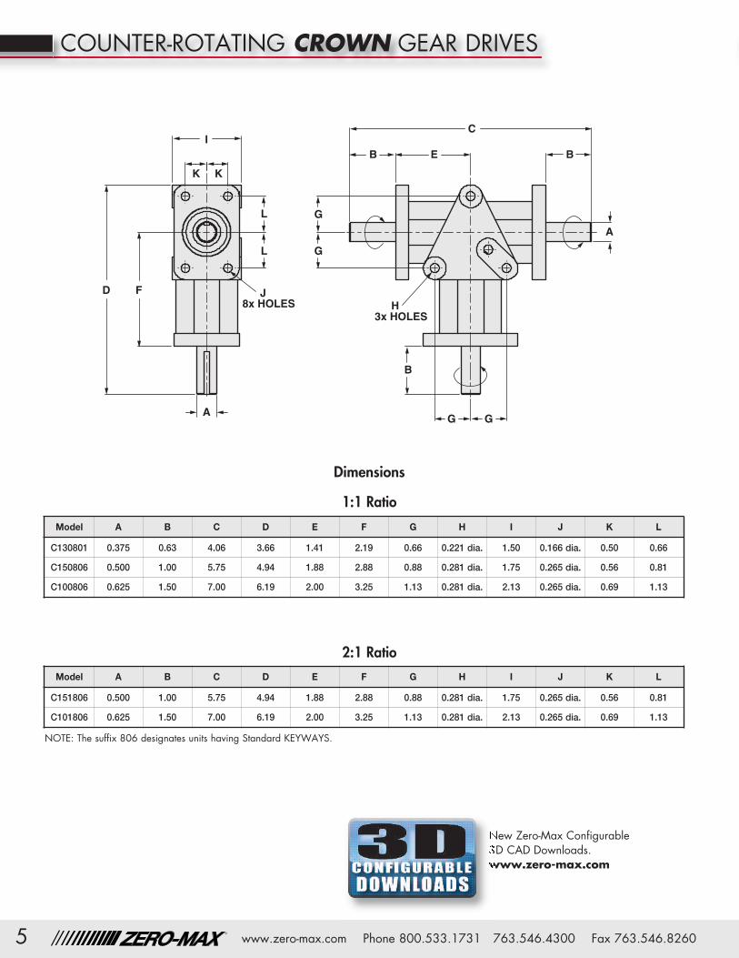
COUNTER-ROTATING CROWN GEAR DRIVES
1:1 Ratio
2:1 Ratio
Dimensions
Model A B C D E F G H I J K L
C130801 0.375 0.63 4.06 3.66 1.41 2.19 0.66 0.221 dia. 1.50 0.166 dia. 0.50 0.66
C150806 0.500 1.00 5.75 4.94 1.88 2.88 0.88 0.281 dia. 1.75 0.265 dia. 0.56 0.81
C100806 0.625 1.50 7.00 6.19 2.00 3.25 1.13 0.281 dia. 2.13 0.265 dia. 0.69 1.13
Model A B C D E F G H I J K L
C151806 0.500 1.00 5.75 4.94 1.88 2.88 0.88 0.281 dia. 1.75 0.265 dia. 0.56 0.81
C101806 0.625 1.50 7.00 6.19 2.00 3.25 1.13 0.281 dia. 2.13 0.265 dia. 0.69 1.13
NOTE: The suffix 806 designates units having Standard KEYWAYS.
L
L
I
K K
FD J8x HOLES
B
G
G
GG
E
C
B
A
H3x HOLES
B
A
New Zero-Max Configurable 3D CAD Downloads.www.zero-max.com
6www.zero-max.com Phone 800.533.1731 763.546.4300 Fax 763.546.8260
®
M � �
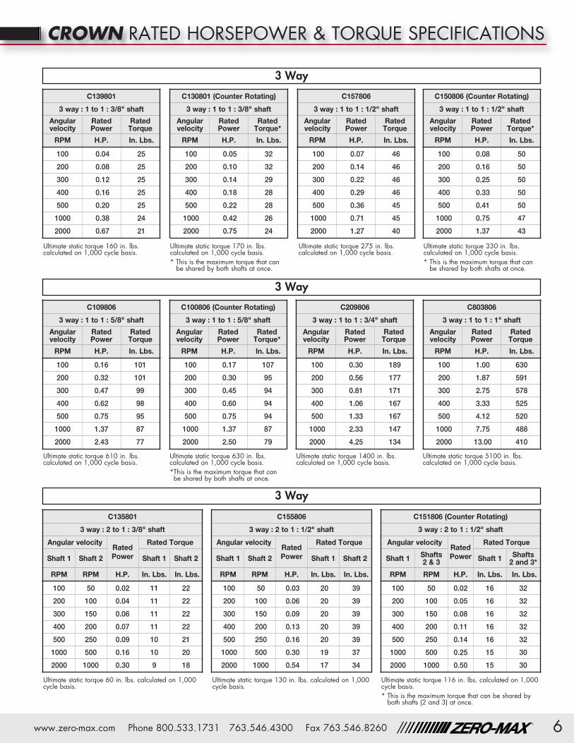
CROWN RATED HORSEPOWER & TORQUE SPECIFICATIONS
Ultimate static torque 170 in. lbs.calculated on 1,000 cycle basis.* This is the maximum torque that can
be shared by both shafts at once.
Ultimate static torque 275 in. lbs.calculated on 1,000 cycle basis.
Ultimate static torque 330 in. lbs.calculated on 1,000 cycle basis.* This is the maximum torque that can
be shared by both shafts at once.
Ultimate static torque 160 in. lbs.calculated on 1,000 cycle basis.
Ultimate static torque 610 in. lbs.calculated on 1,000 cycle basis.
Ultimate static torque 630 in. lbs.calculated on 1,000 cycle basis.*This is the maximum torque that can
be shared by both shafts at once.
Ultimate static torque 1400 in. lbs.calculated on 1,000 cycle basis.
Ultimate static torque 60 in. lbs. calculated on 1,000cycle basis.
Ultimate static torque 130 in. lbs. calculated on 1,000cycle basis.
Ultimate static torque 116 in. lbs. calculated on 1,000cycle basis.* This is the maximum torque that can be shared by
both shafts (2 and 3) at once.
Ultimate static torque 5100 in. lbs.calculated on 1,000 cycle basis.
C139801
3 way : 1 to 1 : 3/8" shaft
Angularvelocity
RatedPower
RatedTorque
RPM H.P. In. Lbs.
100 0.04 25
200 0.08 25
300 0.12 25
400 0.16 25
500 0.20 25
1000 0.38 24
2000 0.67 21
C130801 (Counter Rotating)
3 way : 1 to 1 : 3/8" shaft
Angularvelocity
RatedPower
RatedTorque*
RPM H.P. In. Lbs.
100 0.05 32
200 0.10 32
300 0.14 29
400 0.18 28
500 0.22 28
1000 0.42 26
2000 0.75 24
C157806
3 way : 1 to 1 : 1/2" shaft
Angularvelocity
RatedPower
RatedTorque
RPM H.P. In. Lbs.
100 0.07 46
200 0.14 46
300 0.22 46
400 0.29 46
500 0.36 45
1000 0.71 45
2000 1.27 40
C150806 (Counter Rotating)
3 way : 1 to 1 : 1/2" shaft
Angularvelocity
RatedPower
RatedTorque*
RPM H.P. In. Lbs.
100 0.08 50
200 0.16 50
300 0.25 50
400 0.33 50
500 0.41 50
1000 0.75 47
2000 1.37 43
C109806
3 way : 1 to 1 : 5/8" shaft
Angularvelocity
RatedPower
RatedTorque
RPM H.P. In. Lbs.
100 0.16 101
200 0.32 101
300 0.47 99
400 0.62 98
500 0.75 95
1000 1.37 87
2000 2.43 77
C100806 (Counter Rotating)
3 way : 1 to 1 : 5/8" shaft
Angularvelocity
RatedPower
RatedTorque*
RPM H.P. In. Lbs.
100 0.17 107
200 0.30 95
300 0.45 94
400 0.60 94
500 0.75 94
1000 1.37 87
2000 2.50 79
C209806
3 way : 1 to 1 : 3/4" shaft
Angularvelocity
RatedPower
RatedTorque
RPM H.P. In. Lbs.
100 0.30 189
200 0.56 177
300 0.81 171
400 1.06 167
500 1.33 167
1000 2.33 147
2000 4.25 134
C803806
3 way : 1 to 1 : 1" shaft
Angularvelocity
RatedPower
RatedTorque
RPM H.P. In. Lbs.
100 1.00 630
200 1.87 591
300 2.75 578
400 3.33 525
500 4.12 520
1000 7.75 488
2000 13.00 410
C135801
3 way : 2 to 1 : 3/8" shaft
Angular velocityRatedPower
Rated Torque
Shaft 1 Shaft 2 Shaft 1 Shaft 2
RPM RPM H.P. In. Lbs. In. Lbs.
100 50 0.02 11 22
200 100 0.04 11 22
300 150 0.06 11 22
400 200 0.07 11 22
500 250 0.09 10 21
1000 500 0.16 10 20
2000 1000 0.30 9 18
C155806
3 way : 2 to 1 : 1/2" shaft
Angular velocityRatedPower
Rated Torque
Shaft 1 Shaft 2 Shaft 1 Shaft 2
RPM RPM H.P. In. Lbs. In. Lbs.
100 50 0.03 20 39
200 100 0.06 20 39
300 150 0.09 20 39
400 200 0.13 20 39
500 250 0.16 20 39
1000 500 0.30 19 37
2000 1000 0.54 17 34
C151806 (Counter Rotating)
3 way : 2 to 1 : 1/2" shaft
Angular velocityRatedPower
Rated Torque
Shaft 1 Shafts 2 & 3 Shaft 1 Shafts
2 and 3*
RPM RPM H.P. In. Lbs. In. Lbs.
100 50 0.02 16 32
200 100 0.05 16 32
300 150 0.08 16 32
400 200 0.11 16 32
500 250 0.14 16 32
1000 500 0.25 15 30
2000 1000 0.50 15 30
3 Way
3 Way
3 Way

®
� �
www.zero-max.com Phone 800.533.1731 763.546.4300 Fax 763.546.82607
CROWN RATED HORSEPOWER & TORQUE SPECIFICATIONS
3 Way
Ultimate static torque 210 in. lbs. calculated on 1,000cycle basis.
Ultimate static torque 2170 in. lbs. calculated on1,000 cycle basis.
Ultimate static torque 130 in. lbs. calculated on 1,000cycle basis.
Ultimate static torque 60 in. lbs. calculated on 1,000cycle basis.
Ultimate static torque 1400 in. lbs. calculated on1,000 cycle basis.
Ultimate static torque 160 in. lbs.calculated on 1,000 cycle basis.
Ultimate static torque 610 in. lbs.calculated on 1,000 cycle basis.
Ultimate static torque 275 in. lbs.calculated on 1,000 cycle basis.
Ultimate static torque 540 in. lbs. calculated on 1,000cycle basis.
Ultimate static torque 192 in. lbs. calculated on 1,000cycle basis.* This is the maximum torque that can be shared by
both shafts (2 and 3) at once.
C105806
3 way : 2 to 1 : 5/8" shaft
Angular velocityRatedPower
Rated Torque
Shaft 1 Shaft 2 Shaft 1 Shaft 2
RPM RPM H.P. In. Lbs. In. Lbs.
100 50 0.06 34 68
200 100 0.11 34 68
300 150 0.16 34 68
400 200 0.22 34 68
500 250 0.27 34 68
1000 500 0.51 32 64
2000 1000 0.92 29 58
C101806 (Counter Rotating)
3 way : 2 to 1 : 5/8" shaft
Angular velocityRatedPower
Rated Torque
Shaft 1 Shafts 2 & 3 Shaft 1 Shafts 2 and 3*
RPM RPM H.P. In. Lbs. In. Lbs.
100 50 0.05 31 62
200 100 0.08 30 60
300 150 0.12 28 56
400 200 0.18 28 56
500 250 0.21 26 52
1000 500 0.37 24 48
2000 1000 0.75 23 46
C205806
3 way : 2 to 1 : 3/4" shaft
Angular velocityRatedPower
Rated Torque
Shaft 1 Shaft 2 Shaft 1 Shaft 2
RPM RPM H.P. In. Lbs. In. Lbs.
100 50 0.11 70 140
200 100 0.22 70 140
300 150 0.33 70 140
400 200 0.44 70 140
500 250 0.55 70 140
1000 500 0.99 62 124
2000 1000 1.75 55 110
C805806
3 way : 2 to 1 : 1" shaft
Angular velocity RatedPower
Rated Torque
Shaft 1 Shaft 2 Shaft 1 Shaft 2
RPM RPM H.P. In. Lbs. In. Lbs.
100 50 0.38 236 472
200 100 0.75 236 472
300 150 1.00 210 420
400 200 1.33 210 420
500 250 1.67 210 420
1000 500 3.24 204 408
2000 1000 5.75 181 362
C138801
2 way : 1 to 1 : 3/8" shaft
Angularvelocity
RatedPower
RatedTorque
RPM H.P. In. Lbs.
100 0.04 25
200 0.08 25
300 0.12 25
400 0.16 25
500 0.20 25
1000 0.38 24
2000 0.67 21
C156806
2 way : 1 to 1 : 1/2" shaft
Angularvelocity
RatedPower
RatedTorque
RPM H.P. In. Lbs.
100 0.07 46
200 0.14 46
300 0.22 46
400 0.29 46
500 0.36 45
1000 0.71 45
2000 1.27 40
C108806
2 way : 1 to 1 : 5/8" shaft
Angularvelocity
RatedPower
RatedTorque
RPM H.P. In. Lbs.
100 0.16 101
200 0.32 101
300 0.47 99
400 0.62 98
500 0.75 95
1000 1.37 87
2000 2.43 77
C208806
2 way : 1 to 1 : 3/4" shaft
Angularvelocity Rated Power Rated Torque
RPM H.P. In. Lbs.
100 0.30 189
200 0.56 177
300 0.81 171
400 1.06 167
500 1.33 167
1000 2.33 147
2000 4.25 134
C134801
2 way : 2 to 1 : 3/8" shaft
Angular velocity RatedPower
Rated Torque
Shaft 1 Shaft 2 Shaft 1 Shaft 2
RPM RPM H.P. In. Lbs. In. Lbs.
100 50 0.02 11 22
200 100 0.04 11 22
300 150 0.06 11 22
400 200 0.07 11 22
500 250 0.09 10 21
1000 500 0.16 10 20
2000 1000 0.30 9 18
C154806
2 way : 2 to 1 : 1/2" shaft
Angular velocity RatedPower
Rated Torque
Shaft 1 Shaft 2 Shaft 1 Shaft 2
RPM RPM H.P. In. Lbs. In. Lbs.
100 50 0.03 20 39
200 100 0.06 20 39
300 150 0.09 20 39
400 200 0.13 20 39
500 250 0.16 20 39
1000 500 0.30 19 37
2000 1000 0.54 17 34
2 Way
3 Way 2 Way
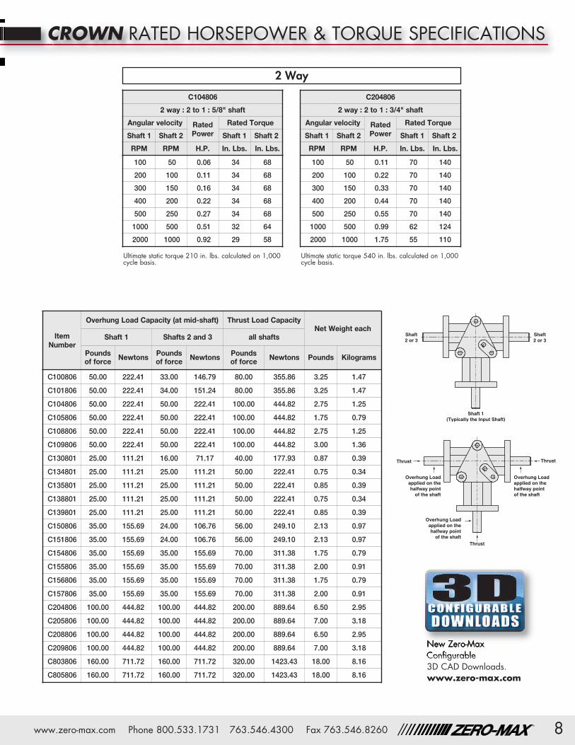
Thrust
Thrust Thrust
Overhung Loadapplied on thehalfway point
of the shaft
Overhung Loadapplied on thehalfway pointof the shaft
Overhung Loadapplied on thehalfway point
of the shaft
Shaft 1(Typically the Input Shaft)
Shaft2 or 3
Shaft2 or 3
8www.zero-max.com Phone 800.533.1731 763.546.4300 Fax 763.546.8260
®
M � �
CROWN RATED HORSEPOWER & TORQUE SPECIFICATIONS
New Zero-Max Configurable 3D CAD Downloads.www.zero-max.com
Ultimate static torque 210 in. lbs. calculated on 1,000cycle basis.
Ultimate static torque 540 in. lbs. calculated on 1,000cycle basis.
C104806
2 way : 2 to 1 : 5/8" shaft
Angular velocity RatedPower
Rated Torque
Shaft 1 Shaft 2 Shaft 1 Shaft 2
RPM RPM H.P. In. Lbs. In. Lbs.
100 50 0.06 34 68
200 100 0.11 34 68
300 150 0.16 34 68
400 200 0.22 34 68
500 250 0.27 34 68
1000 500 0.51 32 64
2000 1000 0.92 29 58
C204806
2 way : 2 to 1 : 3/4" shaft
Angular velocity RatedPower
Rated Torque
Shaft 1 Shaft 2 Shaft 1 Shaft 2
RPM RPM H.P. In. Lbs. In. Lbs.
100 50 0.11 70 140
200 100 0.22 70 140
300 150 0.33 70 140
400 200 0.44 70 140
500 250 0.55 70 140
1000 500 0.99 62 124
2000 1000 1.75 55 110
ItemNumber
Overhung Load Capacity (at mid-shaft) Thrust Load CapacityNet Weight each
Shaft 1 Shafts 2 and 3 all shafts
Pounds of force Newtons Pounds
of force Newtons Pounds of force Newtons Pounds Kilograms
C100806 50.00 222.41 33.00 146.79 80.00 355.86 3.25 1.47
C101806 50.00 222.41 34.00 151.24 80.00 355.86 3.25 1.47
C104806 50.00 222.41 50.00 222.41 100.00 444.82 2.75 1.25
C105806 50.00 222.41 50.00 222.41 100.00 444.82 1.75 0.79
C108806 50.00 222.41 50.00 222.41 100.00 444.82 2.75 1.25
C109806 50.00 222.41 50.00 222.41 100.00 444.82 3.00 1.36
C130801 25.00 111.21 16.00 71.17 40.00 177.93 0.87 0.39
C134801 25.00 111.21 25.00 111.21 50.00 222.41 0.75 0.34
C135801 25.00 111.21 25.00 111.21 50.00 222.41 0.85 0.39
C138801 25.00 111.21 25.00 111.21 50.00 222.41 0.75 0.34
C139801 25.00 111.21 25.00 111.21 50.00 222.41 0.85 0.39
C150806 35.00 155.69 24.00 106.76 56.00 249.10 2.13 0.97
C151806 35.00 155.69 24.00 106.76 56.00 249.10 2.13 0.97
C154806 35.00 155.69 35.00 155.69 70.00 311.38 1.75 0.79
C155806 35.00 155.69 35.00 155.69 70.00 311.38 2.00 0.91
C156806 35.00 155.69 35.00 155.69 70.00 311.38 1.75 0.79
C157806 35.00 155.69 35.00 155.69 70.00 311.38 2.00 0.91
C204806 100.00 444.82 100.00 444.82 200.00 889.64 6.50 2.95
C205806 100.00 444.82 100.00 444.82 200.00 889.64 7.00 3.18
C208806 100.00 444.82 100.00 444.82 200.00 889.64 6.50 2.95
C209806 100.00 444.82 100.00 444.82 200.00 889.64 7.00 3.18
C803806 160.00 711.72 160.00 711.72 320.00 1423.43 18.00 8.16
C805806 160.00 711.72 160.00 711.72 320.00 1423.43 18.00 8.16
2 Way
13200 Sixth Avenue North, Plymouth, Minnesota 55441-5509
Phone: 800-533-1731 (763) 546-4300 Fax (763) 546-8260 www.zero-max.com
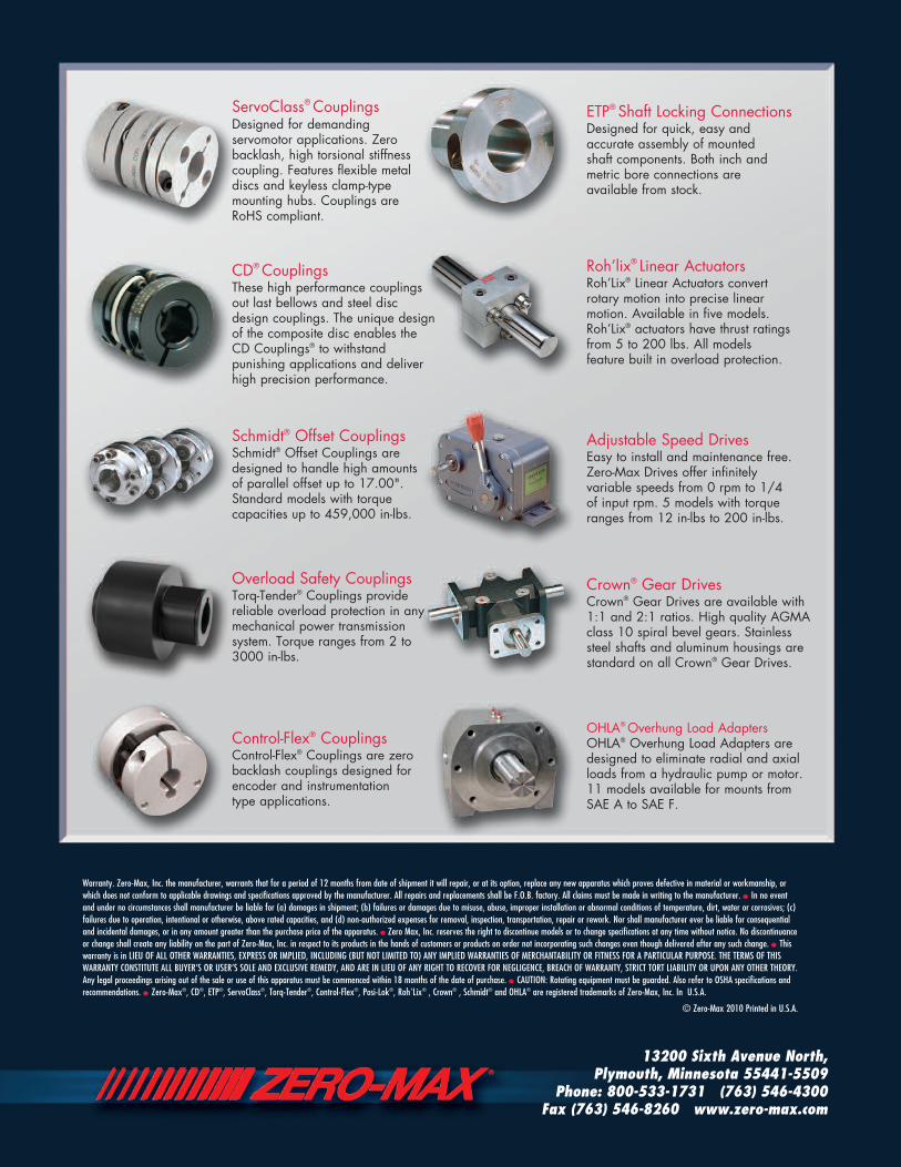
ServoClass® CouplingsDesigned for demandingservomotor applications. Zerobacklash, high torsional stiffnesscoupling. Features flexible metaldiscs and keyless clamp-typemounting hubs. Couplings areRoHS compliant.
Schmidt® Offset CouplingsSchmidt® Offset Couplings aredesigned to handle high amountsof parallel offset up to 17.00".Standard models with torquecapacities up to 459,000 in-lbs.
Overload Safety CouplingsTorq-Tender® Couplings providereliable overload protection in anymechanical power transmissionsystem. Torque ranges from 2 to3000 in-lbs.
ETP® Shaft Locking ConnectionsDesigned for quick, easy andaccurate assembly of mounted shaft components. Both inch andmetric bore connections are available from stock.
Adjustable Speed DrivesEasy to install and maintenance free.Zero-Max Drives offer infinitelyvariable speeds from 0 rpm to 1/4 of input rpm. 5 models with torqueranges from 12 in-lbs to 200 in-lbs.
Crown® Gear DrivesCrown® Gear Drives are available with1:1 and 2:1 ratios. High quality AGMAclass 10 spiral bevel gears. Stainlesssteel shafts and aluminum housings arestandard on all Crown® Gear Drives.
Roh’lix® Linear ActuatorsRoh’Lix® Linear Actuators convert rotary motion into precise linearmotion. Available in five models.Roh’Lix® actuators have thrust ratingsfrom 5 to 200 lbs. All models feature built in overload protection.
CD® CouplingsThese high performance couplingsout last bellows and steel discdesign couplings. The unique designof the composite disc enables theCD Couplings® to withstandpunishing applications and deliverhigh precision performance.
Control-Flex® CouplingsControl-Flex® Couplings are zerobacklash couplings designed forencoder and instrumentation type applications.
OHLA® Overhung Load AdaptersOHLA® Overhung Load Adapters aredesigned to eliminate radial and axialloads from a hydraulic pump or motor.11 models available for mounts fromSAE A to SAE F.
Warranty. Zero-Max, Inc. the manufacturer, warrants that for a period of 12 months from date of shipment it will repair, or at its option, replace any new apparatus which proves defective in material or workmanship, orwhich does not conform to applicable drawings and specifications approved by the manufacturer. All repairs and replacements shall be F.O.B. factory. All claims must be made in writing to the manufacturer. • In no eventand under no circumstances shall manufacturer be liable for (a) damages in shipment; (b) failures or damages due to misuse, abuse, improper installation or abnormal conditions of temperature, dirt, water or corrosives; (c)failures due to operation, intentional or otherwise, above rated capacities, and (d) non-authorized expenses for removal, inspection, transportation, repair or rework. Nor shall manufacturer ever be liable for consequentialand incidental damages, or in any amount greater than the purchase price of the apparatus. • Zero Max, Inc. reserves the right to discontinue models or to change specifications at any time without notice. No discontinuanceor change shall create any liability on the part of Zero-Max, Inc. in respect to its products in the hands of customers or products on order not incorporating such changes even though delivered after any such change. • Thiswarranty is in LIEU OF ALL OTHER WARRANTIES, EXPRESS OR IMPLIED, INCLUDING (BUT NOT LIMITED TO) ANY IMPLIED WARRANTIES OF MERCHANTABILITY OR FITNESS FOR A PARTICULAR PURPOSE. THE TERMS OF THISWARRANTY CONSTITUTE ALL BUYER’S OR USER’S SOLE AND EXCLUSIVE REMEDY, AND ARE IN LIEU OF ANY RIGHT TO RECOVER FOR NEGLIGENCE, BREACH OF WARRANTY, STRICT TORT LIABILITY OR UPON ANY OTHER THEORY.Any legal proceedings arising out of the sale or use of this apparatus must be commenced within 18 months of the date of purchase. • CAUTION: Rotating equipment must be guarded. Also refer to OSHA specifications andrecommendations. • Zero-Max®, CD®, ETP®, ServoClass®, Torq-Tender®, Control-Flex®, Posi-Lok®, Roh'Lix® , Crown® , Schmidt® and OHLA® are registered trademarks of Zero-Max, Inc. In U.S.A.
© Zero-Max 2010 Printed in U.S.A.