right-of-way (row) plan routing manual
TRANSCRIPT

RIGHT-OF-WAY (ROW) PLAN ROUTING MANUAL
DEPARTMENT OF PUBLIC SERVICE DEPARTMENT OF PUBLIC UTILITIES
DEPARTMENT OF RECREATION AND PARKS DEPARTMENT OF TECHNOLOGY
MARCH 13, 2014
1
Purpose: The City of Columbus strives to provide quality and timely review of plans submitted for utility work within its corporation limits. Plan review is essential for new development and various construction projects in the public rights-of-way. The Right-of-Way (ROW) Plan Routing Manual is a guideline for companies proposing to construct facilities in the City’s rights-of-way. All work must comply with City Code, Chapter 903, Standard Drawing 1441, and rules and regulations promulgated by the Director of Public Service for all work in the City of Columbus. Plan Routing Form: The plan routing form, along with a set of design drawings of the proposed work, shall be submitted to the Division of Planning and Operation Permit Section. Staff will review each submittal and determine City departments required to review and approve for proper installation and specifications of submitted plans. The plan routing form will identify each City department involved in the plan review process and provide a reference number that can be used for tracking status of each review. The reference number will become the actual permit number once all necessary approval signatures have been obtained. The applicant will be able to obtain the plan routing form and plan drawings, for routing to the applicable City department(s), within five (5) business days after submitted to the Permit Section. Plan Review: The applicant shall be responsible to collect the necessary approval signatures from each city department identified on their permit plan routing form. Applicant will deliver to each department a copy of the permit plan routing form and proposed design drawing. Each City department identified on the plan routing form will have twenty (20) business days from the date of submittal to complete the initial review. A plan drawing, rejected for any reason, shall be resubmitted with the necessary changes with the original rejected drawing for re-submittal to that department. Ten (10) business days will be allowed for all re-submittals to department(s) for approval. A proposed drawing, rejected for any reason resulting in the proposed work to be relocated, shall be resubmitted for review, to all identified City departments, including the approved department(s). Once the plan is approved by all identified City departments, the applicant shall submit one (1) full set of approved plans, and three (3) half sets (11” x 17”) along with all plan notes and “red-line” plans*, and the signed approved plan routing form to the Permit Section for issuance of permit. A permit will be issued with a start date no earlier than 48 hours after date submitted with approved plans. Upon approval of the plan, the applicant has 180 days from the last signature and date to submit the signed approved plan routing form to the Permit Section. If 180 days has elapsed, the applicant may be required to resubmit a plan routing form and a new set of plan drawings for approval. *Red line plans are proposed plans that have been reviewed and corrected (typically in red pen/pencil) by the City of Columbus plan reviewers. These are known as “red lines” or “mark-ups”.
2
Plan Design: Applicant is responsible for checking with each division to locate and show all the utilities on the proposed design drawings. This procedure does require that the applicant contact each City department for utility location, horizontal, and vertical alignments, topographic features, and a location map identifying the area of work. A Maintenance of Traffic Plan (MOT) and excavation dimensions shall also be included. Plan drawings shall be approved based on the information below. If one or more of these items are not reflected on the proposed design drawings, they are subject for rejection. Plan drawings shall include the following basic criteria for submittal:
Highlight of area of work on detailed location map on 1st page of plans
Address or intersection on plans where work is proposed
Provide distance to the nearest intersections when there is no intersection included on the proposed plan
Include all addresses of each parcel in the working zone
Excavation dimensions (W x L x D)
Show & label all existing and proposed city utilities, pull boxes, manholes, controller cabinets, poles etc…
Identify existing pavement markings, signs, signals, traffic conduit, cables, loop detection (TR)
Proposed work clearly identified (bold, highlight, etc.)
Size of proposed pipe, conduit, or cable with proposed depth
Clearly identify station breaks when no work is proposed
Distance off of ROW or centerline to outside edge of conduit, pipe, pole or equipment
Must state on plans: 3' horizontal and 1' vertical clearance from existing utilities
Scaled plan and profile view; minimum 1" = 40'. Must state the scale on each page
Include a line type legend and symbols list on the proposed plan
Push and receiving pits identified with dimensions
Must state if plan being submitted is based upon other state or local government plans and include the project number, contract number, E-Plan, CC plan, purchase order, etc.
Bore, push, or open cut method stated
Include pole details for proposed poles being placed
Water & sewer lines to include plan number
Utility crossings shall be shown installed perpendicular
Any contractor performing excavation, including but not limited to disturbing the earth with powered or non-powered equipment, drilling and/or boring, shall cause notice to be given to the Ohio Utilities Protection Service (OUPS) at 811 or 1-800-362-2764, or online at www.oups.org at least 48 hours but not more than 10 working days before excavating.
3
Each City department that reviews and approves design plans for proposed utility work has established guidelines that may not be included in the required basic criteria. Applicants shall incorporate the following guidelines from each division. City plan reviewers reserve the right to amend the requirements based upon the current circumstances for the proposed plan area.
DEPARTMENT OF PUBLIC UTILITIES MAPROOM (GIS)
IMPORTANT - Pursuant to O.R.C. §149.433(A) (2) and O.R.C. §149.433(A) (3) (B), the infrastructure
data being provided is not considered a public record and is not to be redistributed. The information being provided is for construction purposes only. Any other use of this data is not permitted. This exemption applies to all images, drawings and maps, both hardcopy and in electronic form, as well as any associated electronic GIS/CAD data which shows the location of the utility’s infrastructure assets.
Please email all infrastructure data requests to [email protected]. Individuals calling into the Maproom to make a data request will be referred to the email address listed. The request will not be processed until an email is received.
All requests should include the following o Name o Company Name o Contact Number (in case we need to contact you for clarification of your request) o City Project Manager (if project has a City Project Manager assigned) o Type of Data being requested (Electric, Water, Sewer or All) o Summarized purpose of the data being requested
Attach an image to the email which clearly shows a bounding box of the area needed (jpg, doc, etc.)
Any areas requested which cover Plant, Tank or Pump Station type infrastructure will need additional approval on the City side and may slightly delay the fulfillment of your request.
The City is currently working on a web-based way for you to submit your data request and will provide an interactive map to draw your bounding box. The timeline for development of this solution is approximately 6 months. We will update this section of the manual as that functionality is developed and released for use.
DEPARTMENT OF RECREATION & PARKS DIVISION OF FORESTRY
Identify the location of all trees within the ROW including their DBH – Diameter at 4.5 ft.
Applicant must contact the City’s Division of Forestry (614-645-6648) prior to any impact to any public vegetation; this includes the cutting of tree roots and branches, bushes, or landscaped area within the city’s public rights-of-way.
Public Trees will be protected against injury or damage to branches, trunks or roots from construction and excavation.
Submit a tree protection plan or drawing for any tree(s) located within 4’ of work zone.
Construction materials and excavation debris, chemicals, fuel, equipment or vehicles are not to be stockpiled, stored, dumped or parked within the drip-line of public trees.
Failure to contact the City Forester will result in the applicant reimbursing the division for the cost of any and all damage as determined by the current edition of the “Guide for Plant Appraisal” published by the International Society of Arboriculture.
4
DEPARTMENT OF PUBLIC SERVICE DIVISION OF PLANNING AND OPERATIONS MAINTENANCE OF TRAFFIC AND TRAFFIC CONTROL
Any work to be performed within the influence area of a signalized intersection, that area includes 400 feet along the mainline, and 200 feet along the side street, shall have all traffic control items shown. This includes, but not limited to, the signal poles and pushbutton locations, loop detection, signal span with signal heads and overhead sign type and location, signal control box, mast arms, pedestrian heads, pedestals, street name signs, lane control signage, all signage within the ROW and all pavement markings.
When work affects pavement lane markings or within a lane with markings farther than the called out influence distances, then all elements associated with those markings shall be shown in their entirety. For example, a signal with turn lanes over 400’, the entire turn lane(s) would be required to be shown as part of the signal.
MAINTENANCE OF TRAFFIC (MOT) PLAN
All work in the public ROW requires a MOT plan including locates for utilities, vacuum excavations or “POTHOLING” within paved areas.
Detailed MOT plans are required for work within signalized intersections or on multiple phased MOT plans.
City typical MOT drawings, tables, and charts may be used with permission of the Maintenance of Traffic Coordinator Plan/Permit reviewer (645-7144).
The plan will be determined by the type of work performed and must be specific to that work.
A detailed MOT plan may consist of, barricades, portable concrete barrier, pedestrian barrier, drum locations and spacing (see OMUTCD part 6 figure 6F-4), use of temporary pavement, use of temporary markings, detour routes, detour and work zone warning signage (OMUTCD table 6C-1), flashing arrow panels, street closures, pedestrian detours and sidewalk barricades with signage, proper taper rates in accordance with OMUTCD part 6 Table 6C-2, flagging set-ups when used, covering of existing signs and signal heads, temporary vehicle detection, and signal timing changes.
All items shall be clearly labeled, stationed or distances shown. Sign design codes and sign sizes shall be shown with each sign.
Special attention must be given to provide the safest and least inconvenient plan for motorists, pedestrians and bicycles alike. ODOT standard MT-drawings will not be accepted.
TEMPORARY AND PERMANENT TRAFFIC CONTROL NOTES
Temporary and permanent traffic control notes shall be inserted with all plans requiring work within the public ROW.
Notes shall be modified to coincide with the scope of work being performed within the public ROW along with the maintenance of traffic plan.
Notes related to the MOT shall be modified specifically for the project. TRAFFIC CONTROL PLAN
All existing and proposed traffic control items shall be shown within the project limits and 200 feet beyond the project limits; this is 200’ before the first and after the last sign for the MOT design, having each intersection shown in full including side street lane markings when work is performed within the public ROW.
Items to include are all pavement markings (stationed), lane widths (dimensioned), all driveways and curb cuts, signage with sign design codes and sizes(stationed with offsets), street names labeled, street name signs, public ROW lines, sidewalks, ADA ramps, crosswalks, utility poles and street lighting, hydrants, and parking meters.
5
DEPARTMENT OF PUBLIC UTILITIES DIVISION OF POWER
Identify the location of all Division of Power (DOP) poles, manholes, pad mount transformers, overhead and underground lines, and duct banks within 25 feet of the work zone.
Label these facilities, in addition to the “UGE” and “OHE” line designators, as belonging to DOP. For example: “DOP UG Street Lighting” with an arrow to the line.
When DOP facilities are present, add the DOP standard note to the plans’ notes. Include the underlined title and all 3 paragraphs. Please provide the description of City facilities to complete the first paragraph. The standard note is:
FOR THE DIVISION OF POWER
The Division of Power (DOP) has (name the facilities, i.e. overhead primary and street lighting on James Rd). The contractor is hereby required to contact OUPS at 1-800-362-2764 forty-eight hours prior to conducting any activity within the construction area. The DOP dispatch office number is: (614) 645-7627 (voice). Any required relocation, support, protection, or any other activity concerned with the City's electrical facilities in the construction area is to be performed by the contractor under the direction of DOP personnel and at the expense of the project. DOP shall make all final connections to DOP’s existing electrical system at the expense of the project. The contractor shall use material and make repairs to a City of Columbus street lighting system by following DOP’s “Material and Installation Specifications” (MIS) and the City of Columbus “Construction and Material Specifications” (CMS). Any new or re-installed underground streetlight system shall require testing as referred to in section 1000.18 of the CMS manual. The contractor shall conform to DOP’s existing Conductor Safety Policy and Hold Card System, MIS-95, copies of which are available from DOP. If you have any questions, call Mihai Orbocea at (614) 645-6851 or Chris Vogel at (614) 645-6963. If any electric facility belonging to DOP is damaged in any manner by the contractor, its agents, servants, or employees, and requires emergency repairs, DOP shall make all necessary repairs, and the expense of such repairs, and other related costs, shall be paid by the contractor to the Division of Power, City of Columbus, Ohio.
Contractor is responsible for following the requirements listed in the standard note, including support and relocation.
Consider a redesign of work when a conflict with DOP facilities is identified.
6
DIVISION OF WATER
All addresses must be shown in the work area zone.
All water crossings must be perpendicular only and provide a profile.
All water main lines must be identified by size and plan number.
Show all water service lines, fire hydrants, curb boxes and valves.
Maintain consistent distance from the ROW; explain if not.
Provide the distance from ROW/center line to proposed conduit, cable or pipe and to existing/proposed water line outside diameter.
The following notes must be included for every plan submitted for water review:
Expose water line at crossing(s) to verify depth and location prior to and during any directional boring.
The contractor is responsible for locating all customers owned service lines. The contractor shall field verify the horizontal and vertical location of any City or customer owned main or service line that may be affected by the proposed construction activities. Field verification shall take place prior to any activity that may jeopardize the integrity of the facility and at a location nearest the point of possible conflict.
Any repair to City or customer owned water lines are the responsibility of the contractor. The contractor shall contact the City of Columbus, Division of Water at 645-7788 prior to any repairs on City owned water facilities. The contractor must be a City of Columbus licensed water contractor.
The contractor shall maintain a minimum of 3' horizontal and 1' vertical clearance from the outside diameter of all water lines and 8' from any “tee” connection, bands and ends of the water lines, from outside diameter to the nearest edge of the facility being placed. DIVISION OF SEWERAGE AND DRAINAGE
The contractor shall measure all clearances (3’ horiz. & 1’ vert.) from the O.D. (Outside Diameter) of the sewer line to the nearest edge of the facility being placed
The width of all sewer lines over 24” in diameter shall be shown on plans and include the wall thickness of the pipe
Approximate pipe wall thickness (for sewers): Figure 1” for every foot of the diameter of the concrete pipe and add 1” to the total.
Example: 36” pipe = 3” + 1” = 4” (+/-) Total wall thickness All brick sewers shall be shown with a 12” wall thickness unless otherwise noted on the sewer record plan.
All sewer lines shall be labeled with the size of pipe and the type of sewer: i.e. SAN=sanitary; STM=Storm; Combo=combination of sanitary and storm
All brick /segmented block sewers shall be labeled BRICK
When crossing a brick/block sewer an additional telemonitoring sewer deposit will be required. Calculation of the deposit shall be based upon the final approved plan. The deposit will be refunded in full when a DVD of the sewer before and after construction is provided to the requestor at the Division of Sewerage and Drainage.
Private sewer service lateral information may be obtained at the sewer/water permit office located at 910 Dublin Rd. Columbus, OH, 3rd floor permit counter or by calling 614 645-7490
The following note(s) shall be included on all plans that include sewers: The contractor is responsible for field verifying the location of all main line sewers and private service laterals. The Contractor is responsible for any damages to sewer mains and/or service laterals. All repairs to the sewer lines and/or service laterals must be completed by a City of Columbus licensed sewer contractor under a separate sewer permit.
For Brick/Block sewers only: The contractor shall maintain a minimum clearance of 10’ horizontal and 5’ vertical from the outside diameter of all brick/segmented block sewers. Brick/block sewers shall not be exposed, as this may cause a collapse of the sewer.
7
DEPARTMENT OF TECHNOLOGY NETWORK INFRASTRUCTURE /TELECOMMUNICATIONS
Provide all required notes to the Department of Technology (DoT)/Cable Interconnect Section/Network Group
Any contractor performing excavation, including but not limited to disturbing the earth with powered or non-powered equipment, drilling must fax any and all documentation to the DoT Help Desk at (614) 645-5758. (Not a member of OUPS)
Any damage done to the City of Columbus cables, conduits, pull boxes or any other City owned facilities will be the sole responsibility of the contractor to repair or replace per discretion of DoT direction.
The contractor shall contact the City of Columbus, DoT, and Cable-Interconnect Section at (614) 645-7756 prior to any repairs performed on City owned fiber optic lines, conduits, inner-ducts, pull boxes or any other City owned facilities.
DEPARTMENT OF PUBLIC UTILITIES DAMAGE PREVENTION Upon notification by OUPS, the City of Columbus will mark the approximate location of City owned water, sewer, and electric facilities to the best of its ability. The excavator shall protect and preserve the markings until those markings are no longer needed. If an excavation will cover a large area and/or progress from one area to the next over a period of time, the excavator shall coordinate the marking of approximate locations of City owned facilities with the actual excavation. The contractor is responsible for locating all customer owned service lines/laterals. The contractor shall field verify the horizontal and vertical location of any City or customer owned main or service line/lateral that may be affected by the proposed construction activities. Field verification shall take place prior to any activity that may jeopardize the integrity of the facility and at a location nearest the point of possible conflict.
Any damages to City or customer owned facilities should first be reported to OUPS by calling 811 or 1-800-362-2764. The permit holder may also call the City utility company at the time of the hit, but OUPS must be contacted first. Any repair to City or customer owned water or sewer facilities are the responsibility of the contractor. Such repairs shall be completed by a City of Columbus licensed sewer and/or water contractor. Repairs to sewer facilities shall require a separate sewer permit.
The OUPS and “Call before you Dig” logos are available for download at:
www.oups.org/Home/AboutUs/OUPSLogo

8
RESOURCES
9
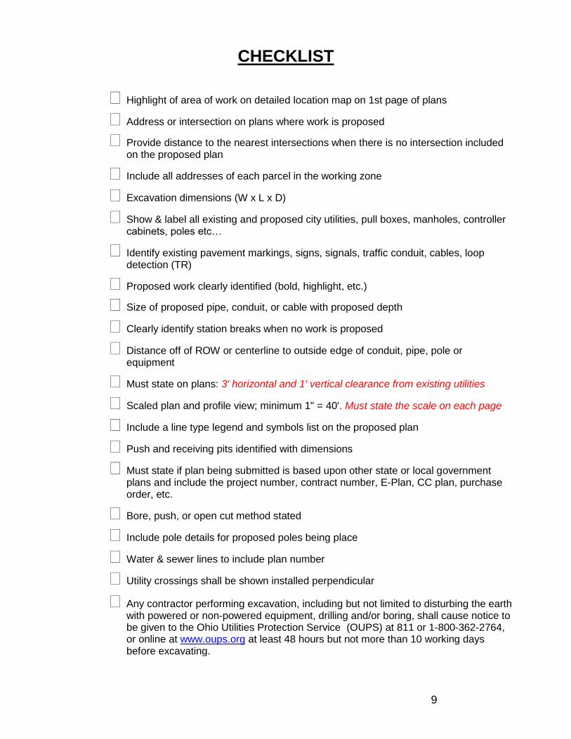
CHECKLIST
Highlight of area of work on detailed location map on 1st page of plans
Address or intersection on plans where work is proposed
Provide distance to the nearest intersections when there is no intersection included on the proposed plan
Include all addresses of each parcel in the working zone
Excavation dimensions (W x L x D)
Show & label all existing and proposed city utilities, pull boxes, manholes, controller cabinets, poles etc…
Identify existing pavement markings, signs, signals, traffic conduit, cables, loop detection (TR)
Proposed work clearly identified (bold, highlight, etc.)
Size of proposed pipe, conduit, or cable with proposed depth
Clearly identify station breaks when no work is proposed
Distance off of ROW or centerline to outside edge of conduit, pipe, pole or equipment
Must state on plans: 3' horizontal and 1' vertical clearance from existing utilities
Scaled plan and profile view; minimum 1" = 40'. Must state the scale on each page
Include a line type legend and symbols list on the proposed plan
Push and receiving pits identified with dimensions
Must state if plan being submitted is based upon other state or local government plans and include the project number, contract number, E-Plan, CC plan, purchase order, etc.
Bore, push, or open cut method stated
Include pole details for proposed poles being place
Water & sewer lines to include plan number
Utility crossings shall be shown installed perpendicular
Any contractor performing excavation, including but not limited to disturbing the earth with powered or non-powered equipment, drilling and/or boring, shall cause notice to be given to the Ohio Utilities Protection Service (OUPS) at 811 or 1-800-362-2764, or online at www.oups.org at least 48 hours but not more than 10 working days before excavating.

10
Sewer Abbreviations and Definitions
RCP.................................................................................... Reinforced Concrete Pipe VCP .................................................................................... Vitrified Clay Pipe CONC ................................................................................. Concrete BR ...................................................................................... Brick and/or Segmented Block STM.................................................................................... Storm line also abbreviated ST or STM SAN.................................................................................... Sanitary line also abbreviated SA or SAN COMBO ............................................................................. Combination Sewer (combined storm and sanitary) INV ..................................................................................... Invert the inside bottom of a pipe. Most sewer elevations are measured to the invert. TP ...................................................................................... Top of Pipe BP ...................................................................................... Bottom of Pipe Crown ................................................................................ Inside top of pipe RP-123 Record Plan ......................................................... As built plans that have been verified and become record CC-123 ............................................................................... This plan could be preliminary and not built yet CO-123 ............................................................................... Usually refers to County sewers annexed into the City of Columbus MM-123 .............................................................................. Older city sewer plans that have not been record planned P Atlas ............................................................................... The sewer department used to document sewers on P Atlas maps. These plans usually do not contain profile information. Useful links:
http://publicutilities.columbus.gov/DocListing.aspx?id=37964&menu_id=942
http://publicservice.columbus.gov/Contractors_and_Consultants.aspx
11
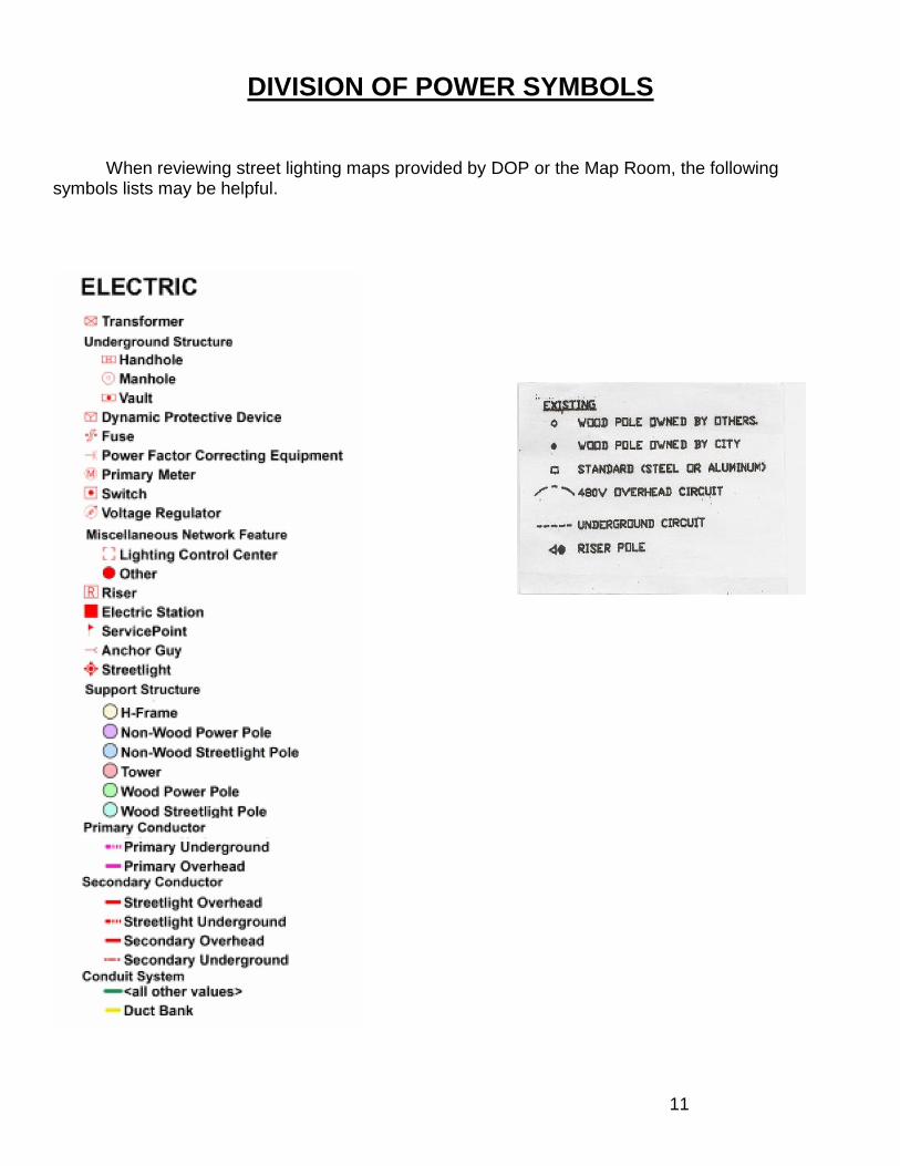
DIVISION OF POWER SYMBOLS
When reviewing street lighting maps provided by DOP or the Map Room, the following symbols lists may be helpful.
12
CAD/Drafting Quality control tips:
Location maps should include at least one major intersection, a north arrow and be large enough to read the Street names.
Leader arrows should touch the line that is being referenced and should not cross text.
Do not obstruct text: example Text over text; lines through text.
Remove all text that does not apply to the current plan.
Text should be large enough to read on a printed plan.
Always indicate the scale a plan is plotted at and verify that the plan plotted to the correct scale.
Verify that street names are spelled correctly and contain the proper suffix, i.e. Walnut Street, Park, Lane, Avenue, and Alley. This is how we recall the proper atlas maps and plans for reviews.
Include a north arrow on every plan sheet.
Do not use red text, leaders and lines. Plan reviewers mark up plans in red ink or pencil, this will avoid confusion.
All routing forms must contain a reference number prior to being submitted to individual departments.
Routing form information should be complete with contact information and street names. The described location should match the associated plans.
13
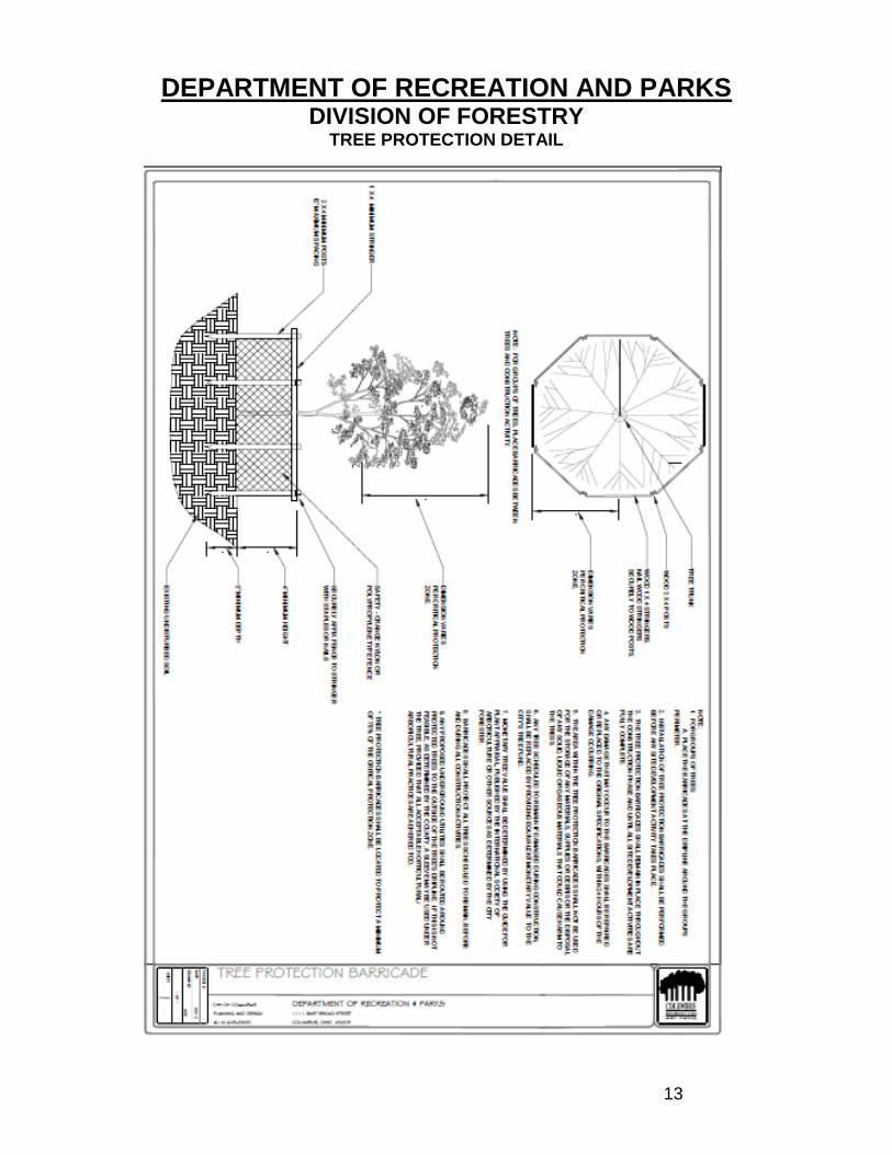
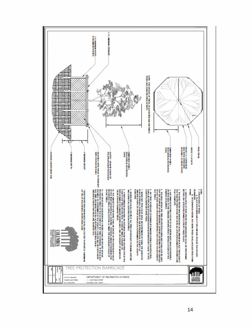
DEPARTMENT OF RECREATION AND PARKS DIVISION OF FORESTRY
TREE PROTECTION DETAIL
14