rights / license: research collection in copyright - non ...8414/eth... · synthesis of...
TRANSCRIPT

Research Collection
Doctoral Thesis
Synthesis of polyphenylenes with removable side chains -towards an all polyphenylene material
Author(s): Jakob, Samuel Paul
Publication Date: 2014
Permanent Link: https://doi.org/10.3929/ethz-a-010112042
Rights / License: In Copyright - Non-Commercial Use Permitted
This page was generated automatically upon download from the ETH Zurich Research Collection. For moreinformation please consult the Terms of use.
ETH Library

DISS. ETH Nr. 21714
Synthesis of Polyphenylenes with removable side chains - towards an all Polyphenylene material
Abhandlung zur Erlangung des Titels
DOKTOR DER WISSENSCHAFTEN der ETH ZÜRICH
(Dr. sc. ETH Zürich)
vorgelegt von
Samuel Paul Jakob
MSc Chemistry ETH Zürich
geboren am 09.09.1983
Von Hombrechtikon, ZH
angenommen auf Antrag von
Prof. Dr. A. Dieter Schlüter Prof. Dr. Paul Smith
Prof. Dr. Holger Frauenrath
2014


Abstract
i
Abstract
Polyphenylenes have been subject of research interest because of their
materials properties since many years. As high molecular weight pure
polyphenylenes are practically insoluble, access to polyphenylenes was limited to
their substituted derivatives. Flexible side-chains attached on the rigid polymer
backbone induced enough solubility to allow synthesis and processing of high
molecular weight polyphenylenes. These side-chains, however, alter and deteriorate
the materials properties characteristic for the rigid polymer backbone. The
development of a process to make such un-substituted polymer materials available
was the subject of the present thesis.
Figure a. Two synthesized monomers were subjected to SPC. The resulting polymer
was processed into a desired shape and by a facile post-processing step converted
into the target material.
The "shaving" approach was envisioned as follows (Figure a): synthesis of a
precursor polymer, decorated with side-chains, which then could be easily removed
from the polymer at a desired point, thus resulting in a pure polyphenylene material.
The concept was developed bottom up, starting from rationally designed monomer
systems, which could be synthesized in multi-gram scale and high purity. Model
studies to investigate side-chain cleavage reactions were carried out. Synthesis of
the precursor polymers I and II (Figure b) by Suzuki Polycondensation (SPC) and
characterization by NMR-spectroscopy, MALDI-TOF mass spectroscopy and GPC
allowed structural analysis and molecular weight determination. The highest
molecular weight obtained for an unfractionated polymer sample was Mw = 50 kDa
for polymer I and Mw= 49 kDa for polymer II. Cyclic oligomers could be identified as a
major side-product, which could be removed by fractionation, leading to significantly
increased molecular weights (Mw = 98 kDa) for polymer I. Cleavage reactions in
solution (I), gel (I) and bulk (I+II) were carried out. Complete cleavage of the side-

ii
chains under various conditions was observed for the transformation of I, while a
complete transformation of II was not observed. Success of the aforementioned
transformations was confirmed by solid-state NMR-Spectroscopy, MALDI-TOF mass
spectroscopy, ATR-IR spectroscopy and elemental analysis.
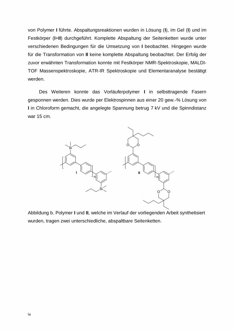
In addition, the precursor polymer I could be processed into self-supporting
fibers. This was done by electrospinning from a 20 wt-% solution of I in Chloroform,
with a voltage of 7 kV and a spinning distance of 15 cm.
Figure b. Polymer I and II synthesized during the present thesis carrying two different cleavable side-chains.
Zusammenfassung
iii
Zusammenfassung
Seit einigen Jahren stehen Polyphenylene, aufgrund ihrer Material-
eigenschaften, im Interessen von Forschungsarbeiten. Da reine Polyphenylene mit
hohem Molekulargewicht praktisch unlöslich sind, ist der Zugang auf deren
substituierte Derivate limitiert. Flexible Seitenketten, welche am rigiden Rückgrat
angebracht werden, erzeugen genug Löslichkeit um Synthese und Verarbeitung von
hochmolekularen Polyphenylenen zu ermöglichen. Diese Seitenketten ändern und
verschlechtern jedoch die Materialeigenschaften, welche durch den rigiden
Polymerrückgrat erzeugt werden. Die Entwicklung eines Prozesses, welcher die
Herstellung solcher Materialien ermöglicht, war das Ziel der vorliegenden Arbeit.
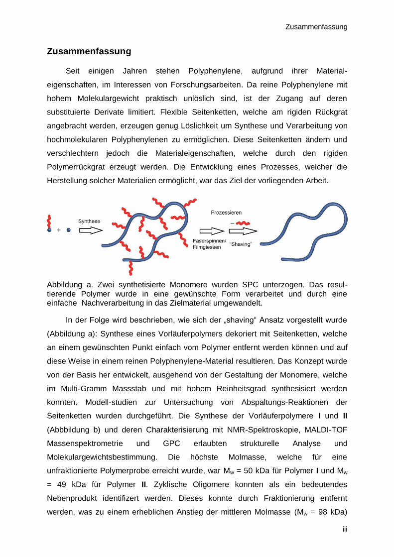
Abbildung a. Zwei synthetisierte Monomere wurden SPC unterzogen. Das resul-tierende Polymer wurde in eine gewünschte Form verarbeitet und durch eine einfache Nachverarbeitung in das Zielmaterial umgewandelt.
In der Folge wird beschrieben, wie sich der „shaving“ Ansatz vorgestellt wurde
(Abbildung a): Synthese eines Vorläuferpolymers dekoriert mit Seitenketten, welche
an einem gewünschten Punkt einfach vom Polymer entfernt werden können und auf
diese Weise in einem reinen Polyphenylene-Material resultieren. Das Konzept wurde
von der Basis her entwickelt, ausgehend von der Gestaltung der Monomere, welche
im Multi-Gramm Massstab und mit hohem Reinheitsgrad synthesisiert werden
konnten. Modell-studien zur Untersuchung von Abspaltungs-Reaktionen der
Seitenketten wurden durchgeführt. Die Synthese der Vorläuferpolymere I und II
(Abbbildung b) und deren Charakterisierung mit NMR-Spektroskopie, MALDI-TOF
Massenspektrometrie und GPC erlaubten strukturelle Analyse und
Molekulargewichtsbestimmung. Die höchste Molmasse, welche für eine
unfraktionierte Polymerprobe erreicht wurde, war Mw = 50 kDa für Polymer I und Mw
= 49 kDa für Polymer II. Zyklische Oligomere konnten als ein bedeutendes
Nebenprodukt identifizert werden. Dieses konnte durch Fraktionierung entfernt
werden, was zu einem erheblichen Anstieg der mittleren Molmasse (Mw = 98 kDa)
iv
von Polymer I führte. Abspaltungsreaktionen wurden in Lösung (I), im Gel (I) und im
Festkörper (I+II) durchgeführt. Komplette Abspaltung der Seitenketten wurde unter
verschiedenen Bedingungen für die Umsetzung von I beobachtet. Hingegen wurde
für die Transformation von II keine komplette Abspaltung beobachtet. Der Erfolg der
zuvor erwähnten Transformation konnte mit Festkörper NMR-Spektroskopie, MALDI-
TOF Massenspektroskopie, ATR-IR Spektroskopie und Elementaranalyse bestätigt
werden.
Des Weiteren konnte das Vorläuferpolymer I in selbsttragende Fasern
gesponnen werden. Dies wurde per Elektrospinnen aus einer 20 gew.-% Lösung von
I in Chloroform gemacht, die angelegte Spannung betrug 7 kV und die Spinndistanz
war 15 cm.
Abbildung b. Polymer I und II, welche im Verlauf der vorliegenden Arbeit synthetisiert
wurden, tragen zwei unterschiedliche, abspaltbare Seitenketten.

Contents
v
Contents
1. Introduction .....................................................................................................................1
2. Motivation ........................................................................................................................3
3. Goals...............................................................................................................................5
4. Theory .............................................................................................................................7
4.1. Suzuki-Miyaura cross-coupling reaction (SMC) ........................................................7
4.2. Suzuki-Polycondensation .........................................................................................9
4.2.1. AA/BB – vs. AB – approach ...............................................................................9
4.2.2. Catalysts – Precursors, concentration and removal .........................................11
4.2.3. Side reactions .................................................................................................13
4.3. All polyphenylene materials – a polymer chemists dream .......................................17
4.3.1. Side-chains and their removal .........................................................................20
4.4. Suzuki-polycondensation by microwave heating.....................................................24
4.4.1. General ...........................................................................................................24
4.4.2. Microwave heated polymerizations ..................................................................24
4.4.3. Microwave assisted SPC .................................................................................25
4.5. Electrospinning .......................................................................................................26
5. Monomer Synthesis .......................................................................................................29
5.1. Diboronic esters .....................................................................................................29
5.2. Dibromide Monomers .............................................................................................29
5.2.1. ‘Kinked’ monomers ..........................................................................................30
5.2.2. Straight monomers ..........................................................................................34
6. Polymer Synthesis .........................................................................................................37
6.1. Synthesis of precursor polymer 42 .........................................................................38
6.1.1. MALDI-TOF MS analysis .................................................................................40
6.1.2. Fractionation of polymer 42 .............................................................................45
6.1.3. Variation of solvents ........................................................................................46
6.2. Synthesis of polymer 77 .........................................................................................48
6.2.1. End group analysis by MALDI-TOF MS ...........................................................48
6.3. Synthesis of precursor polymer 78 .........................................................................50
6.4. Microwave assisted polymerization ........................................................................53
7. Side chain removal ........................................................................................................54
7.1. Shaving of polymer 42 ............................................................................................54
7.1.1. Shaving in solution ..........................................................................................55
7.1.2. Shaving in gel..................................................................................................58
7.1.3. Shaving of macroscopic objects ......................................................................61

vi
7.1.4. Powder X-ray diffraction analysis ....................................................................62
7.2. Shaving of polymer 78 ............................................................................................63
7.2.1. Thermal properties of polymer 78 ....................................................................65
7.2.2. Structural analysis of shaving product .............................................................67
8. Processing of Polymer 42 ..............................................................................................70
8.1. Film formation ........................................................................................................70
8.2. Fiber formation .......................................................................................................73
9. Conclusion and Outlook ................................................................................................80
9.1. Conclusion .............................................................................................................80
9.2. Outlook ...................................................................................................................82
10. Experimental ..............................................................................................................84
10.1. Materials and methods........................................................................................84
10.2. 1,4-di(1,3,2-dioxaborinan-2-yl)benzene[122] (32) ..................................................87
10.3. 1,4-bis(4,4,5,5-tetramethyl-1,3,2-dioxaborolan-2-yl)benzene (52) .......................88
10.4. (3,5-dibromophenyl)dimethyl(propyl)silane (53) ..................................................89
10.5. ethyl 4-amino-3,5-dibromobenzoate[98] (58) .........................................................90
10.6. ethyl 3,5-dibromobenzoate[98] (59).......................................................................91
10.7. (3,5-dibromophenyl)methanol[98] (60) ..................................................................92
10.8. 2-((3,5-dibromobenzyl)oxy)tetrahydro-2H-pyran[27] (61) ......................................93
10.9. 3,5 – Dibromobenzaldehyde[96] (55) ....................................................................94
10.10. 5-Butyl-2-(3,5-dibromophenyl)-5-ethyl-1,3-dioxane (56) ......................................95
10.11. 1,3-dibromo-5-nitrobenzene (64) ........................................................................96
10.12. 3,5-dibromoaniline (65) .......................................................................................97
10.13. tert-butyl (3,5-dibromophenyl)carbamate (62) .....................................................98
10.14. 4,4'-dibromo-2,2'-dinitro-1,1'-biphenyl (67) ..........................................................99
10.15. 4,4'-dibromo-[1,1'-biphenyl]-2,2'-diamine (68) ................................................... 100
10.16. 4,4'-dibromo-2,2'-diiodo-1,1'-biphenyl (69) ........................................................ 101
10.17. di-tert-butyl (4,4'-dibromo-[1,1'-biphenyl]-2,2'-diyl)dicarbamate ......................... 102
10.18. 4,4'-dibromo-2-nitro-1,1'-biphenyl (73) .............................................................. 103
10.19. 4,4'-dibromo-[1,1'-biphenyl]-2-amine (74) .......................................................... 104
10.20. 4,4'-dibromo-2-iodo-1,1'-biphenyl (75) .............................................................. 105
10.21. Suzuki-Polycondensation procedures ............................................................... 106
10.22. Poly(1,1'-4',5-3-(dimethyl(propyl)silyl)phenylene) (42) ....................................... 107
10.23. Poly(1,1'-4',5-3-((tetrahydropyranyloxy)methyl)phenylene) (77) ........................ 108
10.24. Poly(1,1'-4',5-3-(5-butyl-5-ethyl-1,3-dioxan-2-yl)phenylene) (78) ....................... 108
11. Appendix.................................................................................................................. 109

Contents
vii
11.1. Abbreviations and symbols ............................................................................... 109
12. References .............................................................................................................. 112
Acknowledgements………………………………………………………………………………...117
Curriculum Vitae……………………………………………………………………………………119
List of Publications…………………………………………………………………………………120


Introduction
1
1. Introduction
Polymers are a dominant part of our everyday lives. They are one of the three
most wide-spread classes of materials besides metals and ceramics. In 2011 roughly
280 megatons of polymeric materials were produced and sold worldwide. In the
European Union an estimate of 1.4 million people are employed by the polymer
producing and converting industry.[1] Most polymers are used in the packaging,
construction and automotive industries. Virtually every product we use day by day
contains a polymer-based component. Probably the main reason for this is the
extreme versatility of their materials properties, as well as their low production and
processing costs.
Figure 1. Schematic representation of a coiled polymer chain as they exist in solution and in melt (a) and chemical structures of concrete polymer examples (b,c). b) Two commercially highly relevant polymers: Polyethylene 1 (non-aromatic) and polyethyleneteraphthalate 2 (aromatic). c) Two aromatic polymers of relevance to the present thesis: Poly(para-phenylene) 3 and polyfluorene 4, the base structure of commercialized polyphenylene derivatives.
Simplified, polymers can be envisioned as chain-like molecules consisting of an
very large number of links (Figure 1 a). These links (monomers) are connected with
each other to form a larger entity. The individual links are referred to as repeat units
(RUs) and are denoted by square brackets like shown in Figure 1. It should be noted
though that contrary to a woman’s necklace where the links are topologically free to
change their relative orientation in the case of a polymer the individual links are
covalently connected and therefore more limited in their mobility with respect to each
other.
Chapter 1
2
Staudinger postulated in 1920 the existence of polymers, which at that time was
a major step ahead, considering the fact that most of his contemporaries still believed
in the colloidal picture of matter such as leather and cellulose.[2] “Polymerization
processes, broadly speaking, are all processes where two or more molecules are
united to a product of the same composition, but higher molecular weight.”- (H.
Staudinger, 1920, translation from German). His more detailed, strict definition of real
(polymerizations) and artificial (polycondensations) polymerization processes was
slightly revised later. However, the general description of a polymerization process
has been fully accepted in the meantime. A unique feature of polymers compared to
smaller organic substances is that not all molecules in a given sample have the same
molecular weight. This was already noted by Staudinger when investigating natural
rubber.[3] Thus, when referring to molecular weight in the context of polymers, one
usually refers to a molecular weight distribution. The molecular weight of a polymer is
one of the key factors that determine the materials properties of a given polymer
sample, the other being its chemical structure. One way to divide polymers is by
structural differences, e.g., whether they comprise of saturated units only or are
composed of aromatic units. Famous cases for non-aromatic, saturated polymers are
polyethylene (PE), polymethylmethacrylate (PMMA), polytetrafluoroethane (PTFE)
and various polyamides (PA)s. Important aromatic polymers are, e.g.
polyethyleneteraphthalate (PET), the polyparaphenylene family (PPP) and
polyaramides (PARA). For this work of particular interest were PPPs. Aromatic
polymers are known for their outstanding materials properties and some of them
make up for a significant proportion of the yearly production of polymer materials
(PET), while others are mainly used in specific niche applications which have
extremely high demands on materials performance (e.g. PARAs). Polyphenylene
based polymers are, with few exceptions, a poorly investigated family of polymers.
The most prominent members thereof are polyfluorenes, which are used in organic,
light-emitting diodes (OLEDs) and organic solar cells. Little attention has been
brought to the mechanical and thermal properties of polyphenylenes; the present
work covers some of these aspects.

Motivation
3
2. Motivation
Aromatic polymers, compared to many non-aromatic ones, are limited in their
conformational flexibility. This leads to poor solubility of these materials at high
molecular weight in many media because of the unattractiveness to being
molecularly dispersed in a solvent. The entropic gain upon dissolution is small. [4],[5]
The decreased solubility is further caused by strong chain-to-chain interactions like
π-π interactions, which promote close stacking of polymer chains. Thus, not only do
the chains not like to stay in solution but also there is an enthalpic attractiveness for
them to precipitate out. Non-aromatic polymers on the other hand gain a significant
amount of entropy upon dissolution because they then can exercise their entire
conformational space. Additionally, the transition into a solid-state packing is
associated with less liberation of enthalpy. While low solubility can render synthesis,
structure analysis and processing complicated, it can be desirable for certain
applications. Polymers of low solubility are expected to have a better long term
performance, as most chemical degradation processes are slower in solid materials
compared to solutions. Furthermore, insoluble materials are less prone to
environmental stresses such as humidity or vapors of organic solvents. Their
decreased swelling behavior results in an improved overall performance. The
aforementioned characteristics of aromatic polymers not only result in a decreased
solubility, but also in increased melting- and glass-transition temperatures. They
impose major obstacles for synthesis and processing.
Flexible side chains have been shown to increase solubility of conformationally
restricted, unsaturated polymers to a large degree. Thus, synthesizing aromatic
polymers with flexible chain decorations looks like an attractive way to address the
otherwise severe synthesis and processing complications. Of special interest in this
regard is a recent publication by Kandre et al.[6] They showed that a poly(meta-para-
phenylene) with alkyl side-chains can be synthesized by Suzuki-polycondensation
(SPC) followed by a fractionation in astoundingly high molar mass of approx.
250 kDa. This material was soluble in chloroform at room temperature! Its structure
therefore could be fully analyzed by all tools of organic and macromolecular
chemistry. Moreover, the material could be easily processed into durable, fully
transparent films. These films were investigated for their mechanical properties and

Chapter 2
4
found to be comparable in their toughness to commercially available polycarbonate.
This was a remarkable finding which underlines the importance aromatic polymers
may gain supposed they can be synthesized in sufficiently high molar mass. This
finding also very convincingly showed the power of the alkyl chain substitution.
Nevertheless, while this substitution was so effective in this particular case one may
raise the question whether the properties could not have been further enhanced, if
the exact same polymer could be made available without the alkyl chain decoration.
After all, this decoration basically dilutes the properties of the main chain and is
therefore undesired. This is the point at which the present thesis sets in. It will
describe a method by which solubilizing groups are used as long as needed and then
being removed when the polymer is processed into its final form. It was found that
polymer 5 (see Figure 2) has some very interesting mechanical properties (tough and
amorphous). The observed properties of 5 were comparable to those of commercial
polycarbonate (see Figure 2). This is despite the flexible side-chains which were
attached every other phenyl unit.
Figure 2. Structure of polymer 5 and stress-strain curves comparing it to other
polymers. a) high molecular weight poly(meta-paraphenylene) referred to by the authors as PBmP. b) Stress strain curve of PBmP (black) and commercial polycarbonate (PC, grey). Courtesy of “John Wiley and Sons”.
While necessary in synthesis and processing the side-chains are often
undesirable in a targeted material. Especially in high-end applications where specific
materials properties are desired, side-chains are an unwanted feature, since they
usually do not contribute to the desired materials properties and therefore deteriorate
the overall performance of a product.[7] In other words, the active component, the
backbone, is diluted by its decoration with flexible chains. This brought up one of the
a) b)
Motivation
5
key questions leading to the present thesis. What if one could synthesize a polymer
similar to 5 without the flexible side-chains?
3. Goals
As described in the introduction the main goal of this thesis is to provide access
to an aromatic polymer that initially carries flexible chains so as to improve on its
solubility and processability. In the final state on the way to a product, may it be a film
or fiber, the polymer must be designed such that the flexible chains can be
quantitatively be removed so that the bare and insoluble backbone is obtained (6,
Figure 3b). This research goal required several steps of action. They are comprised
of
1. Design of substituents cleavable off aromatic moieties and test experiments
showing the efficiency of such a cleaving process.
2. Synthesis of aromatic monomers applicable to Suzuki polycondensation
(SPC) which carry these substituents.
3. Synthesis of a precursor polymer based on the specially designed
monomers.
4. Analysis of the intermediate structure with the major tools available to the
organic and polymer-chemist.
5. Carry out shaving experiment in order to confirm applicability of the process
to a polymer starting material.
6. Confirm success of the protocol with the available solid state analysis
techniques.
7. Obtain high molecular weight polymer, either by modifying synthesis
conditions until a stock sample of sufficiently high molar mass is obtained or by
fractionation of the stock sample.
8. Investigate possible processing methods for the intermediate polymers.
Chapter 3
6
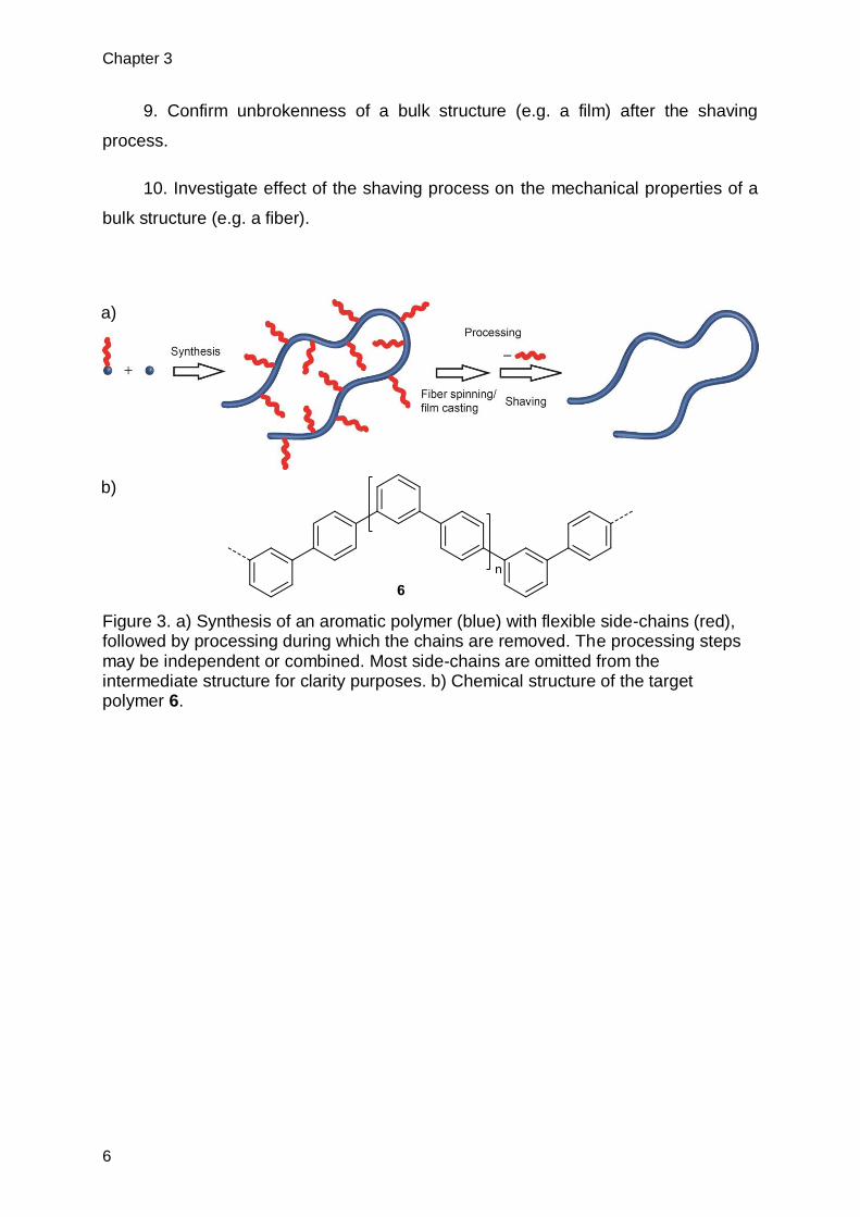
9. Confirm unbrokenness of a bulk structure (e.g. a film) after the shaving
process.
10. Investigate effect of the shaving process on the mechanical properties of a
bulk structure (e.g. a fiber).
Figure 3. a) Synthesis of an aromatic polymer (blue) with flexible side-chains (red), followed by processing during which the chains are removed. The processing steps may be independent or combined. Most side-chains are omitted from the intermediate structure for clarity purposes. b) Chemical structure of the target polymer 6.
a)
b)
Theory
7
4. Theory
4.1. Suzuki-Miyaura cross-coupling reaction (SMC)
Metal catalyzed cross-couplings are a cornerstone in organic synthesis. The
ability to directly form bonds between carbon atoms of all hybridizations has
dramatically changed the pathways in the synthesis of small molecules such as drugs
or natural products. As an example Johansson et al. were able to easily modify a
malaria inhibitor to greatly increase its potency by using SMC.[8] This is just one of
many examples of what a powerful tool these type of reactions have become, they
can be counted as common knowledge for any chemist involved in organic
synthesis.[9]
Miyaura and Suzuki first reported a palladium catalyzed cross-coupling of vinyl-
boronic acids with various halide compounds in presence of a base during
1979.[10],[11] The protocol was discovered during the development flurry of
organometallic coupling reactions in the 1970s. It, however, had some crucial
advantages over protocols involving other transition metal species, be it functional
group tolerance,[12] avoiding toxic starting materials,[13],[14] or substrate scope.[15] In
addition to the aforementioned reasons, the high yields observed in SMC made the
method an extremely popular tool. SMC had such a dramatic impact on organic
synthesis that Akira Suzuki was among the recipients of the 2010 Nobel Prize in
chemistry.
As most transition metal mediated cross couplings, SMC can be divided into
three main steps: Oxidative addition, transmetalation and reductive elimination.
These three steps are believed to form a catalytic cycle. While the basic steps are
generally accepted exact details regarding kinetics and exact transition states are
disputed. Two postulated routes are shown in Scheme 1.

Chapter 4
8
Scheme 1. Two possibilities for a generalized catalytic cycle for SMC.
Despite general notion that the transmetalation is the slowest step in the
catalytic cycle,[16] observations by Aliprantis and Canary suggest that this may not be
so in all cases[17] and Miyaura et al. propose that in fact the oxidative addition is the
rate limiting step.[11] Generally disputed are details involving the transmetalation step,
where Miyaura and Suzuki propose an oxopalladium(II) complex as transition state
and report no direct reaction from palladium bound aryl halides (namely chlorides) [18]
Aliprantis et al. were unable to observe these species, though they were not able to
directly show the exact chemical nature of the boron-species undergoing
transmetalation. A study focusing on pH dependency of SMC showed that boronic
acid derivatives do not undergo transmetalation at pH values < 8. Quaternary
arylborates, however, react readily under the same conditions,[19] proving the
necessity for quarternarization of the boronic acid for transmetalation to occur.
Contrary to the transmetalation step, the oxidative addition step is well understood
and aspects thereof are widely accepted. It is known that electron deficient aromatic
units undergo oxidative addition more readily.[20] Of a much more drastic impact,
though, is the type of aryl halide (or pseudohalide) involved.[9],[21] The generally
observed order of reactivity is I > OTf > Br >> Cl. Omitted from the catalytic cycle in
Scheme 1 are cis/trans isomerizations. These steps proceed during the SMC
reaction, but are difficult to experimentally characterize. However, it is generally
assumed that the oxidative addition and the reductive elimination lead to/require cis-

Theory
9
isomerisation, respectively. The transmetalation step is assumed to take place in the
trans-isomer.[22],[23]
4.2. Suzuki-Polycondensation
The application of SMC to polymers was first reported by Rehahn et al. in
1989.[24] Applying SMC to bifunctional monomers and therefore allow bidirectional
growth by a polycondensation mechanism allowed access to a new family of
polymers previously not obtainable. In its roughly 20 years of existence, SPC has led
to a multitude of polymeric structures, some of which even made it to industrial
application.[25] A few examples are shown in Figure 4.
Figure 4. Polymer 7 was the first soluble high molecular weight polyparaphenylene synthesized by Rehahn and Schlüter[24] 8 is a water soluble polyphenylene synthesized by Brodowski et al.[26] 9 is an example of a kinked polyphenylene investigated by Kandre et al.[6] 10 and 11 are polyfluorene type polymers, while 10 is one of the most basic Polyfluorenes, 11 is of commercial importance.
4.2.1. AA/BB – vs. AB – approach
There are two basic approaches to SPC, the AA/BB- and the AB-approach. In
the former two bifunctional aromatic co-monomers are used (Scheme 2). They carry
either two halide or two boronic acid functions. Their polymerization leads to
polymers in which the two monomers are incorporated in an alternating sequence. In
the case of the AB-approach a single bifunctional monomer is used which contains
both functionalities at the same time. The resulting polymer is now comprised of only
one kind of monomer in its backbone and therefore exhibits directionality. [27] By

Chapter 4
10
design both approaches have their specific advantages and disadvantages. The
aforementioned backbone directionality allows controlled head-tail functionalization.
In addition, the intrinsic stoichiometry match facilitates the polymerization process
(see chapter 6). The price to be paid is the additional synthetic effort required.
Usually AB-monomers are obtained by a desymmetrization of a possible AA/BB-type
monomer. This not only complicates monomer synthesis but also limits substrate
scope. The absence of these synthetic complications is the main advantage of the
AA/BB-approach. Moreover, with a small number of monomers, for each functionality,
a large library of polymeric structures is available. This feature is of additional value if
the structure property relationship of the obtained polymers is of interest. However,
the main issue for AA/BB-type SPC remains the requirement for exact 1:1
stoichiometry of the two monomers. This is a requirement to obtain high molecular
weight polymer.
Scheme 2. Illustration of the AA/BB- and the AB-approach for SPC.
This problem is not limited to SPC, but is a general issue in step-growth type
polymerization chemistry. According to Carothers’ equation high molar mass polymer
is only obtained for high conversions (all step-growth type polymerizations) and molar
fractions close to 1 (AA/BB-type polycondensations).[28] As can be seen in Figure 5b
the degree of polymerization drops rapidly for molar fractions ≠ 1. The plot shown
assumes conversion p = 1. Additionally, as discussed by Carother, for incomplete
conversions the degree of polymerization is even lower (Figure 5a).

Theory
11
Figure 5. Graphical representation of Carothers equation for a) the effect of conversion on the degree of polymerization (Pn) for ideal reaction stoichiometry and b) the effect of molar fraction r on Pn assuming complete conversion.
Issues arising from mismatched AA/BB stoichiometry are of particular
importance when working with small scales or co-monomers of vastly different
molecular weight. A good illustration of the problem in hand was given by Bo et al. [29]
These authors purposely vary the stoichiometry of the two co-monomers to ensure
hitting the ideal stoichiometry. This is a measure often taken when monomer
impurities are present which cannot be exactly quantified.
4.2.2. Catalysts – Precursors, concentration and removal
The most wide-spread although not necessarily best catalyst precursor
employed in SPC is palladium(0)tetrakistriphenylphosphine (Pd(PPh3)4). While still
being a starting point for many optimization studies, it has been replaced by more
active complexes such as Pd(P(p-tolyl)3)3[6], Pd(P(o-tolyl)3)3
[30] and
Pd2(dba)3/SPhos.[27] In all these complexes the metal is in the oxidation state zero.
More convenient options are PdCl2(dppf)[31] or Pd(OAc)2/phosphine ligand (e.g.
SPhos/P(o-tolyl)3).[32],[30] These catalyst precursors are Pd(II)-species, making them
air-stable. However, in order to enter the catalytic cycle they need to undergo
reduction before being able to catalyze the cross-coupling reaction. This can be done
on purpose by using a solvent capable of reducing Pd(II) to Pd(0) [33] or by adding a
suitable reducing agent.[34],[35] If this is not done, reduction may occur by
homocoupling of the boronic acid/ester monomers present (Homocoupling is a known
side-reaction in SPC which will be discussed below).
020406080
100120140160180200
0.0 0.2 0.4 0.6 0.8 1.0
Pn
Conversion p
020406080
100120140160180200
0.5 0.7 0.9 1.1 1.3 1.5
Pn
Molar fraction r
a) b)

Chapter 4
12
Catalyst concentration is a crucial issue in SPC. Most commercial products
employing SPC as synthesis method are designed for opto-electrical applications.
Leftover metal particles origination from decomposed catalyst have detrimental
effects on device performance for example leading to a color shift in OLED. It is
therefore desired to reduce catalyst concentrations as much as possible. Usual
catalyst concentrations for SPC are in the range of 1-3 mol-% in open literature
publications. Kandre and co-workers systematically reduced catalyst loadings in a
successful SPC protocol and observed only small molecular weight decrease for
catalyst loadings down to 0.03 mol-%.[25]For a case of SMC the applied catalyst
loadings went as low as 0.001 mol-% in a conventional reaction setup, [36] in a report
by Leadbeater et al. the authors use Pd-impurities present in commercially available
NaHCO3 as Palladium source and obtain decent yields while using microwave
assisted heating.[37]
As previously mentioned reducing the Pd content of SPC products is of crucial
importance. Murage and Goodson observed that if palladium is not removed directly
after reaction, Pd-clusters are believed to adhere to the formed polymer.[30] The
possibility to remove Pd-traces are manifold, (repeated) precipitations being the most
straight forward[38] but washing with water,[39] soxhlet extraction,[40],[41]
chromatography[29] or scavenger extraction[30] are also feasible options. A very
effective and simple case of scavenger extraction is the use of aqueous NaCN to
wash the polymer solution during workup. [30],[42] Nielsen et al. reported the use of a
specially designed Pd-scavenger (11).[43] Treating a Pd containing solution with this
ligand leads to the formation of complex 12. It has vastly different solubility properties
then most polymers synthesized by SPC. This makes separation of complex 12 and
polymer by precipitation possible. Moreover, 12 has strong UV-absorption band in the
800 nm range, which allows a quantification of Pd leftovers by UV/Vis-spectroscopy.
An emerging field is the use of solid phase supported ligands which allow simple
catalyst removal by filtration after the reaction.[44],[45] Some of these catalysts are of
special interest for industry (some of them have been commercialized) as the
employment of heterogeneous and reusable catalysts is usually sought after since
recycling catalyst greatly improves the cost-benefit ratios of large-scale processes.

Theory
13
Scheme 3. Formation of a quantifiable Pd(0)-complex which can be easily removed from the polymer by precipitation of the latter in MeOH (complex stays in solution).
4.2.3. Side reactions
Side reactions are present in all chemical processes, this is no different for
SPC. Subsequently the most important side reactions are introduced. Most of them
terminate a chain-end and therefore hinder bidirectional growth. They can also alter
the stoichiometric ratio of the two functionalities, which greatly diminishes the
possibility to obtain high molecular weight polymer (see 4.2.1).
4.2.3.1. Ligand Scrambling
A well-known side-reaction involving the ligands of the catalyst is generally
referred to as ligand scrambling. It’s a side-reaction limited to phosphine ligand
containing catalyst systems. Since almost exclusively phosphine based catalyst
systems are employed in SPC this side-reaction is a common obstacle since its very
early history.[46],[47] An example of a ligand scrambling event is given in Scheme 4.
Ligand scrambling events are promoted by higher temperatures but not exclusive to
them. Agrawal et al. also observed ligand Pd-Ar to P-Ar exchange reactions at room
temperature.[48] Moreover, deducting from a temperature ramp experiment Herrmann
and co-workers reported that ligand scrambling events take place at lower
temperatures for electron rich substrates, whereas for electron poor substrates no
Pd-Ar to P-Ar migration was observed prior to catalyst decomposition.[47]
It is evident considering structure 13 in Scheme 4 ligand scrambling can lead to
phosphor incorporation into the polymer backbone which in consequence induces
additional kinks into the polymer backbone or may even lead to a significant degree
of branching as observed by Goodson and Novak[49] This, however, is only the case

Chapter 4
14
for hydrophilic solvents and using Pd(PPh3)4. When using a non-hydrophilic solvent
like DCM and using P(o-tolyl)3 as phosphine ligand, ligands scrambling could be
suppressed to a degree that no 31P-signals could be observed using NMR-
spectroscopy. Schlüter et al. carried out a study aiming at the quantification of
phosphorus incorporation and showed that the phosphorus incorporation was
increasing with increasing molecular weight of the obtained polymer. [50] Besides the
commercially available Pd(PPh3)4 they used Pd[P(p-tolyl)3]3 as catalyst precursors
and toluene/water as reaction solvent. Contrary to Goodsons report Schlüter found
evidence for phosphorus incorporation in all products (ranging from 0.75 – 0.05 mol-
%). Ligand scrambling is the only relevant side-reaction which does not affect the
monomer-stoichiometry in a negative way, as functionalities are not removed, but
simply transferred.

Theory
15
Scheme 4. Example for ligand scrambling processes which take place during SPC reactions.

Chapter 4
16
4.2.3.2. Hydrolytic deboronation
It is generally believed that the hydrolytic deboronation of boronic acids (also
known as protodeboronation) is the side reaction which has the most detrimental
effect on molecular weights in SPC-products.[30] In the reaction the boronic ester
functionality is replaced by a proton. The reaction was discovered, before SPC was
developed.[51] In small molecule synthesis (SMC) this problem is usually
circumvented by the addition of excess of the boronic acid species.[52] This, however,
is not an option for SPC as this would lead to low molecular weight product (see
Figure 5b, Chapter 4.2.1). Protodeboronation is facilitated by ortho-substituents as
reported by Kuivila and co-workers.[53] These authors also propose three different
mechanisms for the hydrolytic deboronation, depending on the pH-value present.
The mechanism relevant for SPC is believed to follow an SE2-pathway (see Scheme
5).
Scheme 5. Proposed mechanism for the hydrolytic deboronation according to Kuivila et al.
Electron poor aryl-systems undergo deboronation more rapidly, but the use of
weaker bases can suppress the side-reaction.[54] Besides using weak bases for
activation of the boronic acid alternative options include decreasing the amount of
boronic acid present in the reaction mixture, this can be achieved by slow addition of
monomer to the reaction solution[27] or by using a Ar--BF3 precursor which is
hydrolyzed during the reaction.[55]
4.2.3.3. Homocoupling
When two arylboronic acid species are symmetrically coupled by a Pd(II) to form
a biaryl this is referred to as homocoupling (Scheme 6). Most commonly in
connection with SPC/SMC when a Pd(II)-catalyst precursor is employed, the catalytic
active species for SMC is generated by homocoupling.[32] This, however, leads to
issues with stoichiometry match or structure imperfection if this reduction is
accounted for and a slight excess of boronic acid monomer is used. The exact

Theory
17
mechanism was postulated by Pleixats and co-workers.[56] A double transmetalation
is followed by reductive elimination, releasing the biaryl species. Homocoupling does
not proceed in oxygen free atmosphere. It should therefore be a minor issue in
properly prepared SPC. Electron donating substituents on the aryl unit are beneficial
for homocoupling.
Scheme 6. General description of the homocoupling reaction.
4.2.3.4. Dehalogenation
The last noteworthy side-reaction is the dehalogenation of aryl halides. The aryl
boronic esters commonly employed in Suzuki-coupling reactions are readily
hydrolyzed under the basic reaction conditions. The generated alcohols can, by -
hydride elimination, lead to palladium-hydride complexes. These hydrides
consecutively lead to Ar-H side-products (Scheme 7).[18] This can easily be avoided
by using tertiary alcohols for boronic acid esterification (e.g. pinacol).
Scheme 7. After addition of a deprotonated alcohol, hydride elimination and reductive elimination the dehalogenated substrate is released.
4.3. All polyphenylene materials – a polymer chemists dream
Aromatic polymers are used in various different applications in our everyday life
whether to contain our daily beverage (PET), as high performance lubricants
(Polyether)[57] or as high stability fibers in safety equipment or sport gear
(polyaramides e.g. KevlarTM). All these materials have in common that the phenylene
units comprised in the polymer backbone are not directly adjoining each other but
connected via linker groups including esters, aramides and the like. These groups
influence the overall polymer properties through increased flexibility and
processability (eg. Polyethers) or increased chain-to-chain interactions

Chapter 4
18
(Polyaramides). However, they are believed to decrease the thermal, oxidative or
photochemical stability of the resulting polymer. The original motivation for the
synthesis of polyphenylenes was the expectation that they would be the best
candidate of all linear polyaromatics with regard to overall stability.[58]
Most syntheses of polyphenylene based structures in fact targeted PPP.
Kovacic et al. were among the first to report a synthesis of an all phenylene based
material.[59] According to their report the reaction of benzene with FeCl3 yielded an
insoluble black material which was “difficult to ignite”. Their obtained product most
likely was a structurally ill-defined oligomer. Additional attempts using Ullman
coupling[60] and the Wurtz-Fittig-reaction[61] were published. However, the relatively
harsh reaction conditions lead to branching. The Kumada-coupling conditions
employed by Yamamoto et al.[62] were a further step ahead towards true PPP.
The first report of a PPP synthesized by SPC was published in 1989 by Rehahn
et al.[24] Using flexible alkyl side-chains to increase solubility, it was possible to obtain
a soluble PPP derivative of 6000 to 8000 g mol-1. Since then SPC has become one of
the most widespread tools to synthesize polyphenylene based materials, not only in
academia but also in industry.[25]
Kinked polyphenylenes have received only little attention compared to their
straight PPP counterparts. The first report of PMPs was included in the report of
Yamamoto et al. towards PPPs.[62] The authors obtained PMP as white powder and
carried out a fractionation by Soxhlet extraction. Both fractions showed relatively high
melting points 190-200 °C for low molecular weight (soluble) fraction and 280-295 °C
for high molecular weight (insoluble) fraction. No quantitative molecular weight
determination was possible for the obtained polymers. Musfeldt et al. reported the
synthesis of kinked polyphenylenes (6, 25 – 28) with varying length of straight
segments between kinks (Figure 6) and the effect on opto-electrical properties of the
resulting materials.[63] The materials were synthesized by Stille-polycondensation and
composed of soluble and insoluble parts. The molecular weight of the soluble fraction
was reported to be 1000-1500 Da.

Theory
19
Figure 6.Kinked polyphenylenes synthesized by Musfeldt et al. The phenyl side-groups of polymers 27 and 28 were introduced to enhance solubility.
A case of a PMP of slightly higher molecular weight (9700 Da) was published by
Reddinger and co-workers.[64] The Ni-catalyzed homo-coupling of the dichloride
monomer 29 afforded the desired polymer 30 which possessed remarkable thermal
stability (Scheme 8).
Scheme 8. Synthesis of PMP 30 by Ni-catalyzed homocoupling. BPY: 2,2’-Bipyridine.
Kandre et al. reported the synthesis of a high molecular weight kinked
polyphenylene (Scheme 9).[6] Polymer 5 was prepared by SPC with Mw = 83 kDa on
a multi-gram scale. Fractionation of 5 by repeated precipitation gave a polymer with
Mw = 255 kDa which could be processed into transparent films. The material
properties exhibited by this polymer were remarkable. As Figure 2b indicates, they
are comparable to those of commercial polycarbonate under regular conditions. If
subjected to chemical stress (exposure to MeOH), the mechanical properties of 5
suffered far less than those of polycarbonate.

Chapter 4
20
Figure 2b. Stress strain curve of Polymer 5 (PBmP) as reference served atactic
polystyrene (Mw: 350 kDa), poly(methylmethacrylate) (Mw: 250 kDa) and a commercial polycarbonate (Makrolon LQ-2847, Bayer). Courtesy of “John Wiley and Sons”.
Scheme 9. Example for a Poly(m,p-phenylene) (PbmP) synthesized by Kandre et al.
4.3.1. Side-chains and their removal
The first reports of side-groups used to enhance solubility of polyphenylenes
was done by Claesson and Kern.[65] They used methyl groups to enhance solubility of
a polyparaphenylene synthesized by Ullmann coupling. The principle to attach longer
side-chains to rigid polymers was since employed numerously.[66],[67] Jones and
Kovacic induced solubility to PPP by alkylation of insoluble material, rendering the
material soluble again.[68] Rehahn et al. then applied the concept of using flexible
chains to synthesize the first polyphenylenes by SPC.[24] This remained a common
feature for all polyphenylene based polymers which were synthesized by the SPC
protocol. Another study by Rehahn et al. could show that beyond a certain threshold

Theory
21
the length of the side-chain does not lead to higher degrees of polymerization. In
addition, the authors showed that not only the length of the side-chain is relevant but
also the density with which they are placed at the backbone.[69] Increased numbers of
longer side-chains as expected showed a higher solubility of the resulting polymer.
However, these side-chains have a tremendous effect on the overall materials
property. When thinking about the opto-electrical properties of PPP bulky side chains
lead to an out-of plane rotation of the phenyl units with respect to each other which
consequently leads to a blue shift[70]. Moreover, interesting mechanical properties of
a rigid polymer backbone are diluted by the flexible side-chains.[7]
Because of the high potential for desirable material properties of polymers with
rigid backbones, different attempts to circumvent obstacles in synthesis and
processing have been made. The two main approaches are the transformable
precursor and the “hairy” precursor approach. The former uses a precursor polymer
with slight alterations in the backbone, which is after polymerization and processing
converted to the target material. The latter utilizes the concept of mitigating solubility
by including side-chains which are designed in a way that their cleavage from the
polymer backbone after processing is facile and quantitative.
4.3.1.1. Transformable precursor
The most widespread use of this method is the xanthate process also called
viscose process used in the production of regenerated cellulose. [71] The same basic
concept was used in the synthesis of polyacetylene[72] and poly(vinylphenylene)[73]
respectively. In the case of polyphenylenes concrete cases for this approach were
employed by Ballard et al.[58] and more recently by Batson and Swager[74] (see
Scheme 10). In the former case FRP polymerization is used to obtain the precursors
(34 a,b,c). As a consequence not exclusive 1,4-connectivity is given but rather a
mixture of 1,4- and 1,2-connectivity.[75] In the latter, the obtained PPP 37 still carries
substituents. The main advantage of the transformable precursor approach, are the
high molecular weights of precursor polymer, which can be obtained. However,
monomers and obtainable polymers are structurally limited. Additionally, incomplete
conversion to the target polymer leads to defects being incorporated into the polymer
backbone.
Chapter 4
22
Scheme 10. a) Ballards route to polyphenylene by a soluble precursor. b) Polyphenylene synthesized by Swager and co-workers by a precursor approach.
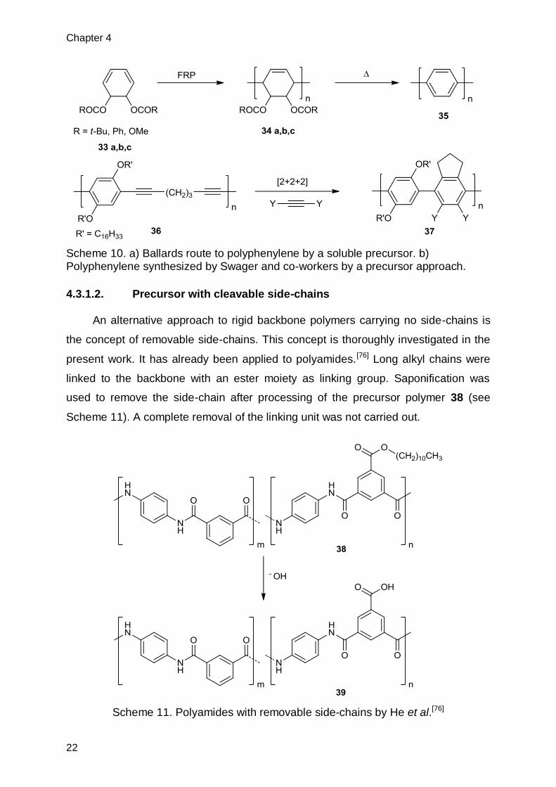
4.3.1.2. Precursor with cleavable side-chains
An alternative approach to rigid backbone polymers carrying no side-chains is
the concept of removable side-chains. This concept is thoroughly investigated in the
present work. It has already been applied to polyamides.[76] Long alkyl chains were
linked to the backbone with an ester moiety as linking group. Saponification was
used to remove the side-chain after processing of the precursor polymer 38 (see
Scheme 11). A complete removal of the linking unit was not carried out.
Scheme 11. Polyamides with removable side-chains by He et al.[76]

Theory
23
This concept was new to polyphenylenes[42] and was investigated as part of the
present work. In concrete terms, a silicon alkyl based side-chain was used, which
was cleaved by proto-ipso substitution. The same concept was later applied to
polythiophenes.[77] Liu et al. previously reported a similar study for polythiophenes.[78]
However, these authors used a thermal process to cleave the side-chains of the
polythiophene backbone, as in the study investigating the concept for polyamides,
the linking group could not be removed from the polymer backbone. In this particular
case this led to desirable properties of the polymer and no further attempts to remove
the linking group were done.
Scheme 12. Removal of side-chains of polythiophenes[77],[78] and polyphenylenes [42] by heat or acid treatment.

Chapter 4
24
4.4. Suzuki-polycondensation by microwave heating
4.4.1. General
In recent years an alternative heating method has started to establish itself in
chemical laboratories. Ever since people started using microwave ovens to reheat
their leftover meals, it’s been a desirable tool for laboratory use because of its abi lity
to quickly heat reaction solutions. Whereas in the early days of microwave ovens in
chemistry labs, sometimes even regular kitchen microwave ovens were being used,
the present microwave ovens used in chemistry labs bear little resemblance to their
domestic counterparts. Magnetic stirring, accurate heating rate, microwave power
and temperature control enable exact tuning of reaction parameters. The possibility
to work under inert atmosphere conditions broadens the scope of possible reactions.
Pressure sensors as well as explosion protected reaction cavities increase working-
safety.
The first reports of organic reactions in microwave ovens were made by Gedye
et al.[79] and Giguere et al.[80] in 1986. Both used regular domestic microwaves to
carry out basic organic reactions like esterification’s, SN2-reactions, ene-reactions or
cope-rearrangements. First reports of Suzuki-Miyaura-crosscoupling in microwave
reactors followed in 1996 by Larhed et al.[81] The main advantage observed in the
studies mentioned above were not necessarily product yield but rather the
significantly reduced reaction times at comparable levels of conversion.
4.4.2. Microwave heated polymerizations
As in small molecule synthesis the amount of research dedicated to using
microwave heating over conventional heating has been increasing drastically in
recent years. Different polymerizations methods such as FRPs, CRPs (mainly
RAFT), ROPs and polycondensations were investigated with regard to their
performance under microwave heating.[82],[83] Because of the demand for high
conversions in polycondensations, the drastically reduced reaction times observed in
microwave-heated reactions are of high interest.
Despite considerable research efforts, it is still unclear whether there really is a
non-thermal microwave effect which leads to an enhancement of rate of
polymerization. Because of the autoclave conditions common for microwave reactors,

Theory
25
very often the observed increase in reaction rate is in good agreement with
Arrhenius’ law which predicts an increased reaction speed by a factor of roughly 2 for
a reaction temperature increase of 10 K.[82] A concrete case showing no non-thermal
microwave effects on reaction speed for a RAFT polymerization was published by
Paulus et al. in 2009.[84] However, in the same year, Roy et al. reported considerable
rate enhancement for another microwave heated RAFT polymerization compared to
conventional heating.[85] In a careful comparative study by Kwak et al. only minimal
differences in rate of polymerization for FRP was observed.[86] The authors claim that
differences in reaction rate can be attributed to insufficient temperature control. More
polar monomers were not found to have an enhanced reaction rate compared to their
non-polar counterparts in co-polymerization experiments. The main advantage of
microwave ovens therefore seems to be the quick and controlled heating at the
beginning of a chemical reaction as well as the access to non-conventional reaction
conditions with regard to temperature and pressure. These features have made
microwave ovens popular tools in otherwise time-consuming processes like reaction
condition screening.
4.4.3. Microwave assisted SPC
The first case of a SPC carried out in a microwave was reported by Nehls et al.
in 2004.[87] In the synthesis of a ladder-type polymer by a precursor route (see Figure
7) the authors obtained the respective precursor polymer 45 in reasonable molecular
weight (Mn: 14.2 kDa, PDI: 1.8, Pn: ~15) and short reaction times (12 min). In a later
publication the same research group reported improved molecular weights (Mn: 29.9
k, PDI: 2.3) using a non-aqueous heterogeneous system (THF, powdered KOH), the
same system was used to polymerize sterically hindered substrates.[88] In a more
recent report, Zhang and co-workers report the microwave-assisted synthesis of
Poly(9,9-dihexylfluorene)s by SPC.[31] In their study, the effects of microwave power
and reaction temperature are investigated in addition to the conventional reaction
parameters like solvent and catalyst species. Within a 14 min reaction time under
ideal conditions (PdCl2(dppf), THF/H2O, 130 °C, 150 W) polymer 46 with a Mw: 40
kDa and a PDI: 1.96 was obtained. However, it should be noted that microwave
assisted polymerization has its very own pitfalls. Zhang et al. observed the formation
of insoluble gel particles if reactions conditions were too harsh as in exceeding a
certain reaction time, reaction temperature or microwave power. They attributed this

Chapter 4
26
gel formation to cross-linking which takes places under harsher conditions.[89] The
proposed cross-linking mechanism is shown in Figure 8.
Figure 7. 47 and 48 were coupled by microwave assisted SPC to form precursor polymer 45.
Figure 8. Possible cross-linking mechanism taking place during microwave assisted SPC.
4.5. Electrospinning
Electrospinning is a versatile technique for fiber-formation of a broad variety of
polymers. Their thickness ranges from a few nm up to tens of µm. This diversity has
lead to electrospun fibers being used for different application purposes. For example
can electrospun polymer mats of nanofibers be used as nanoporous filtration
devices, while compartmentalized fibers are used in medical applications such as
controlled drug delivery. [90]

Theory
27
Scheme 13. Sketch of an electrospinning setup. A polymer solution is pumped slowly through a flat tipped needle with high voltage applied. The electric field leads to the formation of a fine jet towards a grounded, rotating cylinder which serves as target.
During the electrospinning process a polymer solution in a polar solvent is
pumped through a flat tipped needle which is connected to a high voltage source.
The electrically charged solution is deformed at the tip of the needle. If the applied
voltage exceeds a critical voltage, a jet erupts from the droplet, which is accelerated
by the electric field towards a grounded target (Scheme 13).
The choice of target has a significant effect on the shape of the obtained fibers.
A simple metal plate leads to a random mesh of fibers, while a rapidly rotating
cylinder leads to relatively nicely aligned fibers. As the jet is accelerated to high
speeds, the cylinder itself needs to be rotated at high rpm values. Even then some
misaligned fibers may be present. A common drawback of these collectors is the
limitation in fiber length. The fibers need to be cut off the cylinder, which constrains
the maximum fiber length at the circumference of the cylinder. A possibility to obtain
fibers of higher length is the employment of a grounded water bath as target. An
additional advantage is that the target can serve as coagulation bath for slow
evaporating solvents.[91]
In general obtaining fibers from electrospinning is relatively simple given a
polymer solution with a sufficient amount of chain entanglements. There are,
however, a few processes characteristic to electospinning which have to be
considered. One of these processes is called bending. It originates from an

Chapter 4
28
accumulation of like charges. The resulting coulombic repulsion induces a looping
motion of the jet in the horizontal plane. The diameter of these loops increases with
distance from the nozzle, leading to a stretching of the jet and the apparent spinning
distance. This consequently results in reduced fiber thickness.[90] Generally DC-type
high voltage sources are employed in electrospinning. Kessick and co-workers
showed that using an AC-type voltage source greatly reduces bending, which leads
to thicker fibers obtained during the process.[92] An undesirable but frequently-
encountered feature of electrospun fibers is the formation of beads in the fiber. This
effect is accounted to surface tension along the jet and is more pronounced for
solutions of lower concentration. Fong et al. were able to directly correlate the
formation of beads in electrospun fibers with the viscosity of the spinning solution.[93]
A third phenomenon encountered in electrospinning is called spraying. Spraying
occurs when the polymer chains do not have a sufficient amount of entanglements to
form a stable jet. The main reasons for spraying are low molecular weight of the
polymer sample, excessive dilution of the spinning solution or the use of a solvent
which possesses too good dissolution properties for the polymer in question.[94]
Usually of highest interest during the fiber spinning process is the fiber diameter. A
multitude of studies investigate the effect of spinning parameters on fiber size. The
parameters showing the strongest effects on fiber dimensions are viscosity, nozzle
diameter, feed rate and spinning distance. Except for the latter, fiber thickness
increases with increasing values of these parameters. As previously mentioned,
increasing the spinning distance leads to increased stretching of the jet and reduced
fiber thickness. [95]

Monomer Synthesis
29
5. Monomer Synthesis
5.1. Diboronic esters
Two diboronic acid esters were synthesized for the present work. Both were
synthesized starting from the same commercially available starting material phenyl-
1,4-diboronic acid (15). Using 1,3 – Propanediol and Pinacol as dialcohol species
refluxing in toluene at a Dean-Stark-apparatus by means of a condensation reaction
the respective diboronic esters were obtained (see Figure 9). Both monomers could
be synthesized in large scales (22/55 g) and good yields (73/86 %).
Figure 9. Synthesis scheme for the boronic ester monomers 32 and 52.
5.2. Dibromide Monomers
As previously mentioned the big advantage of the AA/BB approach to SPC
chosen for the present work is the large flexibility in monomer design. A number of
monomers bearing different side-chains were synthesized or their synthesis was
attempted and deemed unfeasible for the present work. A synthesis-overview for the
monomers subjected to SPC is shown in Figure 10, whereas the synthesis for a
monomer not subjected to SPC conditions is given in Figure 14.

Chapter 5
30
5.2.1. ‘Kinked’ monomers
Figure 10. Synthesis overview for monomers subjected to SPC conditions.
The synthesis of the most basic dibromide monomer 53 was carried out by a
mono-lithiation of 1,3,5-tribomobenzene (54), the monolithiated species build was
quenched by the respective silylchloride to form 53. Because of the high demands
regarding purity for AA/BB type SPC-monomers a column chromatography to remove

Monomer Synthesis
31
major impurities and a fractionated vacuum distillation to remove excess starting
material and obtain pure monomer as colorless oil was needed. After complete
purification the monomer could be obtained in good yields (63 %) and large
quantities (33 g). The 1H-NMR spectrum (Figure 11) of 53 shows the high degree of
purity. Commonly the 13C-satelite peaks are used as an internal standard to
determine the purity of a sample.[25]
Figure 11. 1H-NMR spectrum of 53 measured in CHCl3 at r.t. Peaks denoted by * are 13C-satelite peaks of the monomer, dashed through peaks are signals belonging to the NMR-solvent (CHCl3, its 13C-satellites and H2O)
From the same starting material 54, using the same reaction type but a different
electrophile (DMF), 3,5 – dibromobenzaldehyde (55) a precursor for monomer 56
was obtained.[96] The final step in the synthesis of 56 was a straightforward acid
catalyzed acetal formation.[97] An alternative route to obtain 55 started with 57 the
dibromination yielded dibromide 58. Subsequent deamination by diazonium salt
formation yielded 59.[98] Selective reduction of the ethylester with DIBAL-H to the
aldehyde yielded 55.[99] However, it should be noted that problems with the selectivity
of the reduction rendered this pathway less feasible than the formerly mentioned one.
A small amount of over-reduced product 60 and starting material 59 required
*
*
*
*
⸗
⸗
⸗ ⸗
Chapter 5
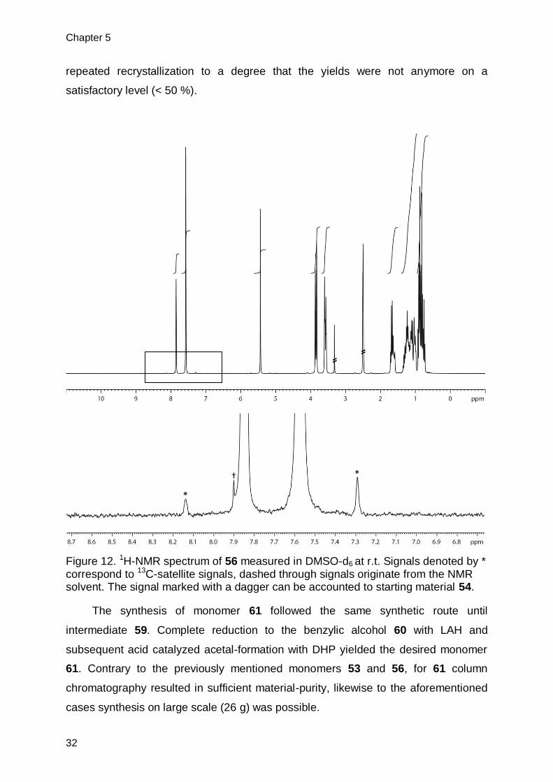
32
repeated recrystallization to a degree that the yields were not anymore on a
satisfactory level (< 50 %).
Figure 12. 1H-NMR spectrum of 56 measured in DMSO-d6 at r.t. Signals denoted by * correspond to 13C-satellite signals, dashed through signals originate from the NMR solvent. The signal marked with a dagger can be accounted to starting material 54.
The synthesis of monomer 61 followed the same synthetic route until
intermediate 59. Complete reduction to the benzylic alcohol 60 with LAH and
subsequent acid catalyzed acetal-formation with DHP yielded the desired monomer
61. Contrary to the previously mentioned monomers 53 and 56, for 61 column
chromatography resulted in sufficient material-purity, likewise to the aforementioned
cases synthesis on large scale (26 g) was possible.
⸗
⸗
*
* †

Monomer Synthesis
33
Figure 13. 1H-NMR spectrum of 61 measured in CDCl3 at r.t. Signals denoted by *
are 13C-satellite signals, dashed through signals originate from NMR solvent and a small solvent impurity (DCM).
In addition, another kinked monomer 62 was synthesized (Figure 14). From 2,5-
Dibromo-4-nitroaniline (63) by deamination via diazonium-salt formation 3,5-Dibromo-
nitrobenzene (64) was formed. Subsequent reduction of the nitro-group afforded 3,5-
Dibromoaniline (65). Protection of the amine group with boc-anhydride yielded the
desired monomer 62 which could be recrystallized from hexane. Contrary to the
previously mentioned monomers, compound 62 was never subjected to SPC
conditions, the reason for this is the yield for the last synthesis step was too poor
(24.4 %) to make large scale synthesis of the monomer feasible.
DCM
*
⸗
⸗
⸗
*
⸗
*
⸗
⸗

Chapter 5
34
Figure 14. Synthesis of 62 starting from 63.
5.2.2. Straight monomers
In an attempt to expand the presented concept from PmpPs to PPPs straight
monomers were also targeted. These monomers were designed in a way that
substituents in ortho-position to the reactive sites were avoided. The reason for this
measure was the desire to exclude negative effects on the oxidative addition step in
the cross-coupling and consequently the polycondensation rate.[100],[101] This goal,
however, came at the price of multiple functionalities which had to be converted in a
consecutive manner. These synthetic complications lead to low yields or no obtained
product at all. The attempts to linear monomers are summarized in Figure 15 and
Figure 16.
The synthesis of possible monomers leading to linear polymer was performed
according to literature procedures.[102] Starting from the commercially available 66 by
an Ullmann-coupling with solid copper in hot DMF the bifunctional monomer-
precursor 67 was obtained in good yields on large scales (70 %, 12 g), subsequent
reduction of the nitro groups with solid tin and HCl in EtOH afforded 68 in very good
yields (95 %). The functional group conversion by Sandmeyer reaction to obtain the
Diiodide-compound 69 only resulted in poor yields (7.2-13 %). Consequently the

Monomer Synthesis
35
synthesis of compound 70 was not driven to completion as the monomer synthesis
would have been unfeasible for the present work. An alternative monomer followed
the same route to the dianiline compound 68, subsequent protection of the amine
groups with boc-anhydride yielded the desired monomer 71 in moderate yields
(48 %).
Figure 15. Synthesis scheme for monomer 70 and 71. The route for monomer 70 was not completed because of low yields for compound 69.
The synthesis of another monomer containing siliconalkyl side-groups was
attempted (see Figure 16). But for the same reason as its closely related bifunctional
analogue (low overall yields) the synthesis was deemed unfeasible.
4,4’-Dibromo-1,1’-biphenyl (72) was nitrated with nitric acid in acetic acid at 100
°C according to a literature known procedure in good yield.[103] 73 was subsequently
reduced using solid tin and HCl in EtOH. This previously employed condition gave 74
in very good yields.[104] In analogy to a literature known procedure the aminogroup of
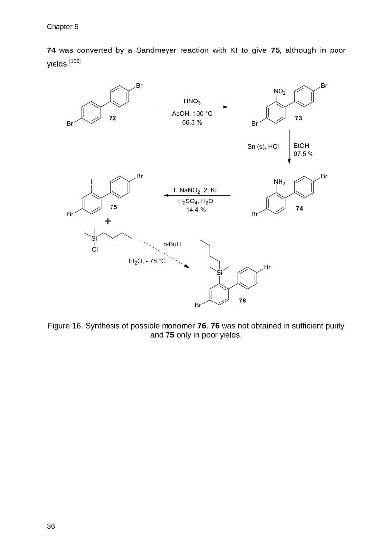
Chapter 5
36
74 was converted by a Sandmeyer reaction with KI to give 75, although in poor
yields.[105]
Figure 16. Synthesis of possible monomer 76. 76 was not obtained in sufficient purity and 75 only in poor yields.

Polymer Synthesis
37
6. Polymer Synthesis
For the present thesis three poly(meta-paraphenylene)s bearing different side-
chains were synthesized (Figure 17). Each system was synthesized bearing a
specific goal in mind. Polymer 42, which will be referred to as the Si-system, was
synthesized in order to explore the possibility to use a simple chemical reaction to
obtain the target polymer 6. The synthesis of 77 (BnzOTHP-system) was a side-
project targeted at end-group analysis in order to get better insight over side-
reactions during polymerization. The last polymer 78 (O,O-acetal-system) was
envisioned to be an alternative precursor for target polymer 6. However, conversion
to 6 should not be carried out by a chemical reaction, but rather by thermal treatment.
Polymer 78 should be heated to a temperature which leads to decomposition of the
side-chain but is still low enough to leave the polymer backbone undamaged.
Following the three different systems are discussed individually.
Figure 17. Chemical structure of polymers 42, 77 and 78 which were synthesized in
the present project.
A few technical hurdles are universally applicable to all synthesized polymers.
As mentioned earlier an exact 1:1 stoichiometry of the two co-monomers is a crucial
element. To exclude low reaction conversion related to stoichiometry mismatch
several approaches were taken. A) weighing directly into the reaction vessel, B)
using smaller vessels specifically for weighing purposes and transfer in solution with
the reaction solvent (repeated rinsing to ensure the transfer is as complete as
possible) or C) Preparation of a monomer stock solution. All techniques have some
advantages and disadvantages; in the case of A) the most limiting factor is that for
technical reasons only certain reaction scales are applicable, the reason being that
the combined weight of reaction vessel and monomer quickly exceeds the maximum

Chapter 6
38
load of high precision balances. The largest disadvantage of B) is the human error
that comes into the equation during transfer from weighing vessel to reaction vessel
even tiniest splashes of monomer solution can lead to a significant mismatch in
stoichiometry. C) should be the method of choice when it comes to screening of
reaction conditions. The caveat here is that monomer stability in solution can be an
issue and needs to be individually evaluated. In the present work for most cases
option B) was employed, exceptions to this were studies involving microwave
assisted SPC for which C) was chosen. A) was rarely used for the aforementioned
reason.
The conditions used by Kandre in his very successful synthesis of a kinked
polyphenylene were chosen as a starting point for SPC (see Figure 18).[6]
Optimization studies were not the primary goal of the present thesis and therefore not
carried out in detail, if at all.
Figure 18. Overview of the synthesis towards polymers 42, 77 and 78. The conditions
employed were the starting point for polymerizations in the present thesis.
6.1. Synthesis of precursor polymer 42
Polymer 42 could be synthesized reproducibly in high yields using the given
reaction conditions. If yields were below 90 % this was a strong indication of flawed
reaction or work-up conditions, such as uncontrolled fractionation. The precursor
polymer was analyzed by the common organic synthesis tools. 1H-NMR and 13C-
NMR proof the structural integrity of the precursor material (Figure 19,Figure 20).
Small signals next to the strong Si-CH3 signal could be accounted to end-groups.
This was confirmed by NMR analysis of fractionated samples (see Figure 21). With
decreasing molecular weight the intensity of the signals in question increased with
respect to the main signal.

Polymer Synthesis
39
Figure 19. 1H-NMR spectrum of polymer 42 in CHCl3 at r.t.
Figure 20. 13C-NMR spectrum of polymer 42 in CDCl3 at r.t.

Chapter 6
40
Figure 21. Sections of 1H-NMR spectra of three fractions of polymer 42 recorded in
CDCl3 at r.t. Molecular weight of the fractions increases from top (red) to bottom (black). The peaks marked with * are silicon-grease impurities.
6.1.1. MALDI-TOF MS analysis
For detailed end-group analysis of particular interest was the MALDI-TOF mass
spectrum (Figure 22 a&b). The stepwise insertion of the two monomer units can be
seen clearly, giving strong evidence for a step-growth type polymerization
mechanism. This was of particular interest since very recently for a similarly kinked
monomer different observations were made.[27] A similar mechanism could be
envisioned, if in a first step all monomers dimerize pairwise and the thus formed AB-
type monomer undergoes further polymerization. This, however, is not observed.
Unfortunately unambiguous end-group assignment could not be carried out for
polymer 42, the reason being fragmentation processes taking place during ionization.
The, by-design, labile nature of the Si-based side-chain becomes an obstacle in
analysis.
*
*

Polymer Synthesis
41
Figure 22. a) MALDI-TOF mass spectrum of polymer 42, showing a large number of
signal series. The nature of these different signals are either different end-groups or fragmentation of the side-chains during the ionization process. b) Section of the MALDI-TOF mass spectrum of polymer 42, spanning the m/z-range of two repeat units. MA (green) corresponds the mass of the phenyl unit carrying the side-chain, while MB (red) represents the unsubstituted phenyl unit of the polymer.
b)
a)

Chapter 6
42
Figure 23. ATR-IR spectrum of polymer 42.
ATR-IR spectroscopy showed the main characteristics to be expected (see
Table 1). The C-H stretching bands at 3030 (aromatic) and 2951-2864 cm-1 were of
particular importance as they are a clear indication for the presence or absence of
the side-groups (further detailed in 7.1.1). Moreover, the bands observed are
summarized in Table 1.
Table 1. Summary of the IR-signals observed for polymer 42.
The main advantage of the current approach, however, is the possibility to carry
out molecular weight determination by GPC. This allows an estimation of the mass
for the target polymer. A typical GPC curve for SPC leading to 42 is shown in Figure
24.
Signal [cm-1] Assignment
1587, 1512 Aromatic st (C-C, C=C)
1455, 1383 CH3 δ (as, sy)
1247 Si-CH3 δ (sy)
1136, 1061, 1014, 992 C-H δ in plane
822, 762 Si-(CH3)2 framework vibrations
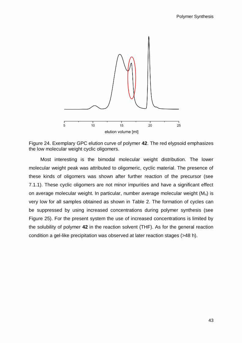
Polymer Synthesis
43
Figure 24. Exemplary GPC elution curve of polymer 42. The red elypsoid emphasizes the low molecular weight cyclic oligomers.
Most interesting is the bimodal molecular weight distribution. The lower
molecular weight peak was attributed to oligomeric, cyclic material. The presence of
these kinds of oligomers was shown after further reaction of the precursor (see
7.1.1). These cyclic oligomers are not minor impurities and have a significant effect
on average molecular weight. In particular, number average molecular weight (Mn) is
very low for all samples obtained as shown in Table 2. The formation of cycles can
be suppressed by using increased concentrations during polymer synthesis (see
Figure 25). For the present system the use of increased concentrations is limited by
the solubility of polymer 42 in the reaction solvent (THF). As for the general reaction
condition a gel-like precipitation was observed at later reaction stages (>48 h).

Chapter 6
44
Table 2. Summary of molecular weights and yields obtained for SPC of 53 and 32/52.
For the entry marked with an asterisk, it is reasonable to assume that during the precipitation step of the work-up a significant amount of low molecular weight species was lost.
Figure 25. GPC elution curves of polymer 42 synthesized in three different concentrations.
The reduction in cyclic oligomers is evident. They seem to be the major product
in the case of the lowest concentration investigated, but barely visible for the highest
concentration. For the medium and highest concentration, a precipitation during
synthesis was observed. This necessitated the use of relatively low concentrations
Entry Monomers & Batch
Mn [kDa] Mw [kDa] PDI Polymer obtained [g]
Yield [%]
1 32 & 53 A 4.0 9.3 2.3 2.66 88.1
2 32 & 53 A 5.0 48.4 9.7 2.24 99.6
3 32 & 53 B 6.5 14.9 2.3 3.75 98.6
4 32 & 53 B 8.2 49.7 6.1 5.08 96.6
5* 52 & 53 B 9.9 93.8 9.5 2.73 83.0
6 52 & 53 C 5.6 32.9 5.9 4.99 93.5
7 52 & 53 C 3.9 26.6 6.8 1.06 94.5

Polymer Synthesis
45
during polymer synthesis, leading to a significant degree of cyclic oligomers present
in the product. As these low molecular weight species would significantly deteriorate
the mechanical properties of a polymer material, their removal was paramount.
6.1.2. Fractionation of polymer 42
Polymer 42 was fractionated by three different methods: top down precipitation
fractionation,[106] fractionation by open GPC and fractionation by precipitation with a
selective solvent. The results are illustrated in Figure 26. The top down precipitation
fractionation method employed CHCl3 as solvent and MeOH as non-solvent, fractions
accounting for 10 % of total sample mass were obtained. Fractionation by open GPC
was carried out with toluene as eluent. In the precipitation with selective solvents
toluene was used as solvent and EtOH as non-solvent in a ratio of 1:1.
Figure 26. GPC elution curves illustrating two fractionation techniques on a sample of polymer 42. a) top down precipitation fractionation, black: desired sample, red: stock sample. b) Fractionation by open GPC, comparison of the three obtained fractions (high: black, medium: blue, low: magenta).

Chapter 6
46
Figure 27. GPC elution curve of a precipitation fractionation with selective solvents of polymer 42. In red the stock sample, in black the gel phase after two precipitations, in blue the sol phase of the first precipitation. Intensity differences are due to varying concentrations of polymer 42 in the GPC samples.
The top-down precipitation fractionation and fractionation by GPC gave samples
of high molecular weight with small (top down precipitation) to negligible (GPC) low
molecular weight species. However, in these methods, the obtained high quality
fractions account for a low percentage of overall sample mass (10% and 30 %
respectively). This is nicely illustrated by the GPC elution curve of the medium
molecular weight fraction in the GPC-method, which still contains a large amount of
high molecular weight material. This is the main advantage of the selective solvent
which allowed removal of low molecular weight material with minimal loss of high
molecular weight polymer.
6.1.3. Variation of solvents
A common feature for almost all SPC reactions carried out with the Si-system
was the observation of a precipitate at late reaction stages. This led to the
assumption that THF might not be the ideal solvent for this system, as molecular
weight was not limited by reaction conversion but rather by solubility of product in the
reaction solvent. The results of the solvent variation studies are summarized in Table
3. The extremely low molecular weight material of 42 obtained after SPC in

Polymer Synthesis
47
toluene/water is believed to be a matter of phase-transfer kinetics. This is supported
by the observation of increased reaction speed when adding increasing amounts of
THF to the solvent mixture (see Figure 28). THF can be viewed as a phase transfer
catalyst. Contrary to a report by Bo et al;[107] polymer 42 obtained from SPC in
THF/toluene/water mixtures was of lower molecular weight than the one obtained
from SPC in THF/water.
Table 3. Results of the solvent variation study, showing the highest molecular weights of polymer 42 could be obtained using THF as solvent. All reactions were
carried out with water as co-solvent.
Figure 28. Molecular weight vs. reaction time for four different SPC conditions (Table 3, entry 2-5). Entry 2: black, entry 3: red, entry 4: blue, entry 5: green.
Entry Org. Solvent Mp [kDa] Mw [kDa]
1 Dioxane 16.1 20.4
2 Toluene 0.45 0.50
3 THF 26.0 33.0
4 Toluene/THF (1/1) 12.9 13.3
5 Toluene/THF (1/2) 8.8 22.0

Chapter 6
48
6.2. Synthesis of polymer 77
The synthesis of 77 was carried out as a side-project with the main intention to
get more information about the end-groups situation of polymer obtained after SPC.
As for polymer 42 a clear determination of the end-groups was not possible (see
chapter 6.1.1). The side-group was altered in a way to facilitate ionization and be
sufficiently stable so fragmentation is avoided. In a report by Hohl et al. a THP-
protected benzylic alcohol was shown to have excellent ionization properties.[27]
Subjecting monomers 61 and 32 to the SPC conditions used for the Si-system lead to
polymer 77. Premature precipitation of a white powder was a sign for the low
solubility of 77 in the reaction solvent. This was underlined by reaction monitoring by
GPC which showed a halt in polymer growth after 16 hours (Figure 29).
Figure 29. Superimposed GPC elution curves of polymer 77. Samples of the same volume were taken out of the reaction solution, diluted and freeze dried, before subjecting them to GPC analysis.
6.2.1. End group analysis by MALDI-TOF MS
The MALDI-TOF mass spectrum of 77 showed a major series and several
minor ones (Figure 30 a). The former was observed as sodium adduct, whilst the
latter were observed as sodium adduct in some cases and as neat molecule ions in
others. The fact that the cyclic series is so dominant does not necessarily have to

Polymer Synthesis
49
indicate that these species are predominant in the sample composition but rather that
these oligomers “fly” better during MALDI-TOF analysis. As a consequence it is
possible that the detection of less dominant species is suppressed. A more detailed
analysis of the minor series (Figure 30 b) gives useful information about side-
reactions present. Most noteworthy is the absence of free boronic acid end-groups in
any of the series. Only one series with a boronic ester end-group was observed. This
finding indicates that deboronation reactions are one of the major obstacles to high
molecular weight. Ligand scrambling accounts for a multitude of observed series,
both expected termini are observed and no clear distinction with respect to which
intermediate is more prone to ligand scrambling is possible. Although the early
precipitation of 77 may adulterate the observations given by MALDI-TOF mass
analysis. To get a more conclusive idea of the end-group situation and detrimental
side-reactions early precipitation should be avoided.
6
7
8 9
10
11
12
13
14
15 16
17 18 19 20 21
a)

Chapter 6
50
Figure 30. a) MALDI-TOF mass spectrum of 77. The main series corresponds to
[cycle + Na]+ the number next to the signals corresponds to the number of r.u. comprised in the cycle. b) Section of a MALDI-TOF spectrum of 77, giving an
overview over the observed end-groups. All unmarked series are present as sodium adducts [M+Na]+ while the one marked with an asterisk is the [M]+ species.
6.3. Synthesis of precursor polymer 78
Monomer 56 was designed in a way to incorporate the acetal structure
responsible for the improved ionization properties, while containing flexible chains to
mitigate solubility. It was subjected to the same SPC conditions as the previously
mentioned monomers 53 and 61. The obtained molecular weights are summarized in
Table 4.
Table 4. Molecular weights obtained for selected polymerizations of 56 and 32/52 leading to polymer 78.
Entry Monomers Mn [kDa] Mw [kDa] PDI Mass obtained [g]
Yield [%]
1 56 & 32 8.1 39.5 4.9 1.03 86.5
2 56 & 52 10.2 36.0 3.5 4.12 98.1
3 56 & 52 9.0 48.9 5.4 3.60 90.2
m/z
Br/
PO
(p-t
oly
l)2 (
AB
)
Br/
toly
l (A
B)
Br/
OH
(A
B)
+ B
r/to
lyl (A
B)A
PO
(p-t
oly
l)2/P
O(p
-toly
l)2 (
AB
)A
OH
/OH
B(A
B)
H/P
O(p
-toly
l)2 A
(BA
)
PO
(p-t
oly
l)2/P
O(p
-toly
l)2 (
AB
) +
H/H
(A
B)A
H/P
O(p
-toly
l)2 (
AB
)
PO
(p-t
oly
l)2/O
H (
AB
)
toly
l/to
lyl B
(AB
)
toly
l/P
O(p
-toly
l)2 (
AB
)
H/O
H (
AB
)
Br/
H (
AB
) +
H/H
B(A
B)
toly
l/to
lyl (A
B)
+ toly
l/O
H
B(A
B)
H/B
O2C
3H
6 (
AB
) *
toly
l/H
B(A
B)
*
b)

Polymer Synthesis
51
A goal of the synthesis of 78 was to investigate the effect of using a pinacol
protected diboronic acid instead of a propan-1,3-diol protected one. Unfortunately,
only qualitative conclusion can be drawn. To avoid suppression of the signals of
interest by signals originating from cyclic oligomers, the investigated sample was
fractionated prior to analysis. The drastic reduction in cyclic species compared to
unfractionated samples is nicely visible in the GPC elution curve shown in Figure 31.
End group analysis by MALDI-TOF mass spectrometry revealed an increased
amount of series carrying boronic acid or boronic ester end-groups compared to the
case of polymer 77. In addition, the number of proton endgroups at the bromine
terminus, resulting from protodebromination by β-elimination are greatly diminished
(see Figure 32). This is a strong sign that using a pinacol protected boronic acid
largely enables suppression of the proto-debromination side-reaction (see 4.2.3.4).
The major signal, however, could not be univocally assigned, since the possible end-
group patterns which are composed of two commonly observed end-groups cannot
be distinguished by MALDI-TOF spectrometry.
Figure 31. GPC elution curve of a fractionated sample of polymer 78. The same
sample was analyzed by MALDI-TOF spectrometry (see Figure 32).

Chapter 6
52
Figure 32. a) Full MALDI-TOF mass spectrum of 78. b) Enlarged section of a) some
series of the type [M+Na]+ and [M]+ could be observed, contrary to previous cases for similar polymers no cyclic species were observed.
HO
-B(A
B)-
P(t
ol)
2 /
H-B
(AB
)-P
O(t
ol)
2
To
l-(A
B)-
PO
(to
l)2 +
Na
To
l-B
(AB
)-P
(to
l)2 +
Na
H-(
AB
)-B
(OH
) 2 +
Na
H-B
(AB
)-H
Br-
(AB
)A-B
r +
Na
HO
-B(A
B)-
OH
+ N
a
tol-
(AB
)-B
(Este
r)
H-B
(AB
)-B
(Este
r) +
Na
HO
-B(A
B)-
P(t
ol)
2 /
H-B
(AB
)-P
O(t
ol)
2
a)
b)

Polymer Synthesis
53
6.4. Microwave assisted polymerization
As the molecular weights obtained by conventional reaction techniques were
believed to be too low for processing into robust self-standing structures. One of the
main obstacles identified was the relatively poor solubility of 42 in the reaction solvent
THF. Previous attempts to obtain polymer 42 with increased molecular weight by
changing solvents or using solvent mixtures failed (see 6.1.3). Microwave reactors
have been previously used for SPC.[25, 87] Microwave reactors designed for the use in
chemistry labs allow the use of increased pressure. In consequence, increased
reaction temperatures are possible which should lead to an increased solubility of X
in the reaction mixture. The following aspects were investigated: effect of
temperature, reduction in reaction time, age of catalyst precursor. All experiments
were carried out from the same monomer stock solution to avoid discrepancies
associated with monomers stoichiometry. The resulting molecular weights are
summarized in Table 5.
Table 5. Molecular weight of polymer 42 obtained by microwave assisted SPC of 53 and 52. Entry 1 serves as reference and was obtained by conventional heating
methods. Entries indicated by asterisk suffered uncontrolled fractionation during the workup process.
Entry Reaction time [h]
Reaction temperature [h]
Catalyst batch
Catalys age
Mn [kDa] Mw [kDa]
1 96 72 - Fresh 3.9 26.6
2* 90 72 - Fresh 8.0 25.3
3* 90 100 - Fresh 10.8 42.7
4* 16 120 - Fresh 20.0 77.0
5 90 120 - Fresh 4.9 29.6
6 48 120 - Fresh 4.8 27.6
7 24 120 - Fresh 4.2 27.8
8 12 120 - Fresh 4.3 32.6
9 48 120 A Fresh 4.0 30.0
10 48 120 A 2 days 4.3 35.7
11 48 120 A 7 days 5.5 27.8
12 48 120 B Fresh 4.2 11.3
13 48 120 B 2 days 4.3 24.6
14 48 120 B 7 days 4.5 22.4

Chapter 6
54
As the results indicate the molecular weight of obtained polymer was largely
unaffected by changes in reaction time and catalyst age. One of the main drawbacks
of microwave assisted SPC is the lack of online reaction control. While simple
observation by eye-sight might seem a rudimentary technique it gives valuable
information about state of the catalyst. Early decomposition of the catalyst precursor
would give valuable information with regard to possible mistakes that happened
during the reaction setup. It is therefore possible that certain discrepancies in Table 5
are due to random errors like leaks in the degasing vessel or oxygen contamination
occurring during transfer to the microwave oven. All reaction mixtures contained a
solid black mass once the reaction was finished. At first this solid was removed by
filtration (see entry 2-4 in Table 5). This, while being interesting to obtain high
molecular weights without the additional effort of a fractionation, is an uncontrolled
process and leads to falsified results.
7. Side chain removal
The removal of side chains as introduced in 4.3.1.2 was commonly referred to
as ‘shaving’ in the present work. Shaving attempts were performed for polymers 42
and 78 respectively and are treated separately because of their differing nature.
7.1. Shaving of polymer 42
Shaving of 42 is performed by the addition of a strong acid to a polymer
solution. Ipso-substitution of aryl-silanes by electrophile is a well-known textbook
reaction.[108] In the present study TfOH was employed as proton source.
Scheme 14. Shaving of polymer 42 dissolved in toluene by addition of TfOH.

Side chain removal
55
7.1.1. Shaving in solution
At first the shaving reaction was performed in a refluxing toluene solution. Upon
addition of the acid a white powder precipitated within a few seconds, to ensure
reaction completion stirring and heating was continued for 24 hours. Quenching of
the reaction was performed by addition of triethylamine. The whole mixture was
subjected to soxhlet extraction with isopropanol, hexane and diethylether. The
relatively low yield (61 %) can be attributed to powder residues which are sticking to
the glass wall or extraction thimble which cannot be removed without compromising
the purity of the sample. Analysis methods are limited to solid state methods. These
include solid state NMR-spectroscopy (1H, 13C, 29Si, 19F) (Figure 33 - Figure 36),
ATR-IR-spectroscopy (Figure 37), MALDI-TOF mass spectrometry (Figure 38) and
elemental analysis (Table 6).
Figure 33. 1H-MAS NMR spectrum of polymer 42 (blue, top) and polymer 6 (black,
bottom) measured at 21 kHz spinning frequency.

Chapter 7
56
Figure 34. 13C-CPMAS NMR spectrum of polymer 42 (blue, top) and polymer 6
(black, bottom) measured at 8 kHz spinning frequency. Main signals are marked with arrows, remaining signals are spinning side-bands.
Figure 35. 29Si-MAS NMR spectrum of polymer 42 (blue, top) and polymer 6 (black,
bottom) measured at 5 kHz spinning frequency.
Figure 36. 19F-MAS NMR spectrum of polymer 6, spinning frequency was 21 kHz.

Side chain removal
57
As the spectra in Figure 33, Figure 34 and Figure 35 show signals related to the
side-chain (Silicon and alkyl signals) largely disappear, only in the 1H-NMR spectrum
a small residual signal of alkyl protons is visible. A fluorine NMR (Figure 36) was
recorded to ensure no reagent was bound to the polymer during the shaving process.
Moreover, ATR-IR spectra of polymer 42 and 6 were measured (Figure 37). When
comparing the blue (42) to the black (6) curve a few major features are observable.
Firstly the aliphatic C-H stretching vibrations below 3000 cm-1 are not observable
anymore in polymer 6 contrary to the precursor polymer 42. In addition, the
characteristics Si-CH3 symmetric deformation vibration at 1247 cm-1 disappears in
addition a strong band at 819 cm-1 is not observable after the shaving a band which
could be assigned to a Si-CH3 vibrational mode.[109]
Figure 37. IR-Spectra of polymer 6 (black) and polymer 42 (blue).
MALDI-TOF mass spectrometry analysis for polymer 6 was more conclusive
than for its precursor (see 6.1.1). Contrary to the large amount of mass series
observed in MALDI-TOF analysis of the precursor only one series is clearly visible in
the case of polymer 6. When assuming the Dibromide monomer is referred to as
monomer A and the diboronic ester monomer as monomer B, a key feature of the
MALDI-TOF spectrum shown in Figure 38 can be explained as follows. As indicated

Chapter 7
58
by observations from literature and made in the present work (6.2) AA/BB-type SPCs
follow a strict step-growth mechanism.[50] This would lead to an expected spectrum
containing (AB)n, (AB)nA and B(AB)n type structures of whatever end-groups
observed. However, the mass spectrum of polymer 6 only shows one series of
masses all with AB mass intervals (m = 152.06). This is a strong evidence for the
formation of cyclic product. The absolute masses observed correspond to the
masses expected for [(AB)n]+ (n = 7-16).
Figure 38. MALDI-TOF mass spectrum of polymer 6, a) magnification of a signal
showing its isotope pattern. b) simulated isotope pattern for the expected signal.
Furthermore elemental analysis showed that indeed the material in question
has the chemical composition of an all aromatic compound.
Table 6. Elemental analysis for acid treated polymer 6, the values for the expected content are deduced from target polymer 6.
7.1.2. Shaving in gel
The desire to apply the thus discovered concept to a bulk structure like a
polymer film or a fiber asked for slight adjustments. If no solvent is employed most
likely only the periphery of the bulk structure would be affected by the shaving
process, leading to core-shell differentiated bulk structures, which was undesirable.
Thus a solvent needs to be used to swell the macroscopic structure into a gel like
Element Found content [%] Expected content [%]
C 93.58 94.70
H 5.40 5.30
b)
a)

Side chain removal
59
object in order to make its interior accessible to the employed reagent. For this,
however, toluene would not be feasible, because of its dissolution properties of the
precursor polymer. Therefore different solvents were employed to investigate the
scope of the present concept. Cyclohexanone, 1,4-dioxane and p-xylene were
chosen for further investigations mainly because of their ability to possess sufficient
interaction with the precursor polymer in order to form a swollen object while not
possessing the ability to dissolve higher molecular weight material of polymer 42. In a
first step a gel particle was subjected to shaving conditions. The results thereof are
illustrated in Figure 39 -Figure 41. Shaving in cyclohexanone was unsuccessful, even
at high temperature (Figure 39). The reaction in 1,4-dioxane is slow (10 days reaction
time) and requires slightly elevated temperature (50 °C) to achieve a satisfactory
degree of conversion. An interesting aspect can be taken from Figure 40. Even at
prolonged reaction times, a reduction of the aliphatic signals can be observed. This is
a clear sign that using the present methodology the core-shell problem can be
properly addressed. The most rapid conversion was found using 1,4-xylene as
swelling agent (Figure 41).
Figure 39. 13C-CP MAS NMR spectra of polymer 42 (top, blue) and the product of
TfOH treatment in cyclohexanone (black, bottom) at 110 °C for 24 h.

Chapter 7
60
Figure 40. 13C-CP MAS NMR spectra illustrating the course of the shaving reaction at room temperature (if not noted otherwise) of polymer 42 (top, blue) to polymer 6 in
1,4-dioxane. Reaction time: 21 h (green), 3 days (magenta), 10 days (red), 10 days and 50°C (black, bottom.
Figure 41. 13C-CP MAS NMR spectra of polymer 42 (top, blue) and 6 after TfOH
treatment in 1,4-xylene (black, bottom).

Side chain removal
61
7.1.3. Shaving of macroscopic objects
Since during the shaving process a substantial amount of mass is lost,
maintaining the macroscopic structure of a bulk object is important. If the shaving
process would lead to a large number of cracks in the film, the protocol would have to
be adjusted. A pressed film (~ 230 µm thickness) was first swollen and thereafter
subjected to acid treatment. If the film was swollen in 1,4-dioxane, only small pieces
could be recovered. Contrary to this, swelling in 1,4-xylene allowed recovery of the
acid treated film in one piece. 13C-CP MAS NMR-spectroscopy showed that shaving
is proceeding with a large degree of conversion within three days (Figure 42).
Figure 42. a) Photograph of the shaved film, broken in half (object size:~0.5 cm). b) 13C-CP MAS NMR spectra of a compressed film of polymer 42 (top, blue) and the
product of TfOH treatment after swelling the film in 1,4-xylene (black, bottom).
The film is recovered in one piece but there are two noteworthy points. Firstly
the color of the film turns brown after acid treatment; this is an issue that might
demand alterations to the system. Color changes might be a result of degradation
products not being able to escape from the bulk structure. The film is expected to
collapse from its gel state during treatment, entrapping degradation products. An
alternative explanation could be that the strong acid undergoes undesired reactions
with the endgroups. Secondly, the film is not recovered flat as before treatment, but is
deformed during treatment (bending). This is a possible obstacle when thinking about
applications as a change in morphology from the processing shape is not desirable.
a) b)
0.5 cm

Chapter 7
62
However, the latter issue might arise from inhomogeneous acid deposition, an issue
that could be resolved by engineering proper reaction conditions.
7.1.4. Powder X-ray diffraction analysis
The effect of shaving on the crystallinity of the film was investigated by X-ray
diffraction (XRD).The powder diffraction patterns can be seen in Figure 43. A
superposition of the integration of the two diffraction patterns is shown in Figure 44.
Figure 43. Powder X-ray diffraction patterns of a pressed film of 42 before shaving (left) and 6 after shaving (right). Distance between sample and detector: 130 mm, wavelength: 0.71 Å, inversed greyscale.
A clear assignment of the signals is not trivial. The most intense reflections
have their maximum at 1.15 Å-1 (42) and 1.26 Å-1 (6) respectively. This corresponds
to interplanar distances of 5.40 Å (42) and 4.96 Å (6). Common π-π stacking
distances in related polymers are commonly 3.3-3.8 Å but in some cases can go up
to 4.2 Å.[110],[111] A report on oligomeric paraphenylenes shows that direct π-π
interactions between two phenylene segments are not the main feature of order in
these compounds.[112] The unit cell dimensions observed for these compounds vary
between 5.63-5.55 Å in their shortest dimension. This indicates that a similar type of
orientation between the chains is present. In addition, what can be noted is that the
main structural feature of the two compounds indicates a denser packing in the target
material 6 compared with the precursor 42. Minor reflections are summarized in
Table 7.

Side chain removal
63
Table 7. Summary of the observed reflections for interplanar distances for polymer 42 and 6.
Figure 44. Superposition of the integration of the two diffraction patterns of a film based of 42 (blue) and the acid treated 6 (black). Signal intensity is given versus
reciprocal distance.
7.2. Shaving of polymer 78
Whereas the work focused on polymer 42, which was employing a chemical
reaction in order to remove the undesired side-chains, a whole different approach
d-spacing of 42 [Å] d-spacing of 6 [Å]
7.68 4.96 (main reflection)
5.40 (main reflection) 4.29 (shoulder)
2.28 3.41 (shoulder)
2.20
2.02

Chapter 7
64
was taken for polymer 78. Using thermal treatment to remove the side-chains is
intriguing. If a clean process can be developed there are significant advantages for
the thermal process compared to a removal by chemical reaction. The main
advantage being that for a thermal process the sample is treated in a homogeneous
fashion.
As a first test reaction like experiment the monomer carrying the side-chain (56)
was analyzed by electron impact high resolution mass spectrometry (EI-HRMS,
Figure 45). The two most interesting fragmentations observed are the signals at
171.14 amu and 260.85 amu respectively. The former corresponds to the mass of the
complete side-chain. The latter could be associated with a fragmentation of the side-
chain. A C=O group remains on the aromatic ring while the remainder of the side-
chain is cleaved off.

Side chain removal
65
Figure 45. EI-HRMS spectrum of 56. Top: Mass range 0-215 m/z, bottom: mass range 215-450 m/z.
7.2.1. Thermal properties of polymer 78
To gain some insights into the thermal properties of polymer 78 a temperature
ramped thermo-gravimetric analysis (TGA) Figure 46 a) and differential scanning
calorimetry (Figure 46 b) was carried out. Slow degradation starts to set in at 300 °C,
at 395 °C maximum degradation speed is observed. Ideal degradation conditions are
expected for temperatures between 300 °C and 375 °C. Higher temperatures could
lead to unwanted degradation. Figure 46 c shows that for temperatures below 200 °C
no major degradation takes place. The degradation process starts between 200-
S. Jakob/Schlüter; SJ 095 - 1A - 116:11:49
21-Sep-2011
m/z10 20 30 40 50 60 70 80 90 100 110 120 130 140 150 160 170 180 190 200 210 220 230 240 250 260 270 280 290 300 310 320 330 340 350 360 370 380 390 400 410 420 430 440 450
%
0
100
EI9841 16 (1.644) Cm (16:20-29:33) Magnet EI+ 5.20e370.0776
55.0565
41.0463
29.057327.0447
69.0700
56.0634
112.1236
111.1163
83.0852
84.0926
95.0845
405.9958
403.9981171.1381
113.1279
154.9490125.1325
262.8526
260.8539
234.8570184.9419 198.9570
402.9908264.8510
265.8575 327.0784 374.9779358.9487
407.9940
408.9969

Chapter 7
66
250 °C, making these temperatures the lower limit where side-chain cleavage is still
possible.
Figure 46. a) TGA trace of polymer 78 recorded with 5°C /min heating rate. b) DSC-curve of polymer 78, showing a Tg at 200-225 °C. Curve of second heating, cooling traces are omitted. c) TGA curves of polymer 78, all curves are recorded isothermal
after ramping with a rate of 20 °C/min to the given temperature. d) TGA traces of long time isothermal measurements of polymer 78 for three chosen temperatures. Black
250 °C, blue 300 °C and red 350 °C.
Using 375 °C as cleaving temperature, a weight loss of 57.8 % was observed
(see Figure 47). As the side-chain accounts for 53.1 % of the mass in each r.u. this
value indicates that 375 °C is too high for a long-term degradation process and the
reaction would have to be stopped preemptively.

Side chain removal
67
Figure 47. TGA curve of polymer 78. Recorded isothermal after heating to 375 °C
with 20 °C/min.
In a series of long term measurements a relatively clear picture of the kinetics of
the partial degradation process was obtained (Figure 46 d). Degradation is sluggish
at 250°C. Even excessive reaction times (> 5 days) resulted in a mass loss of less
than 10 % and after 5 days degradation came close to a halt. A steady but still slow
degradation was observed for a reaction temperature of 300 °C. Extrapolated a
degradation time of three weeks was expected for complete degradation of mass
corresponding to the side-chains. If degradation temperature was increased to 350°C
relatively rapid degradation was observed at first which decelerated after
approximately 45 % mass loss and leveled at 50.5 % mass lost. Therefore even for
350°C no complete degradation of the side-chains can be assumed. Consequently
375 °C reaction temperature and a pre-emptive reaction stop was chosen for the
side-chain degradation reaction.
7.2.2. Structural analysis of shaving product
The shaving was carried out in a tube furnace, polymer 78 was placed in a
ceramic bowl. In parallel a comparative sample was treated with the same
temperature profile in the thermo-gravimetric analyzer (Figure 48).
∆m = 57.8 %

Chapter 7
68
Figure 48. TGA trace of a comparative sample for the thermal decomposition reaction of 78. Heating with 6 °C/min to 375 °C, isothermal for 180 min, cooling with 10
°C/min.
∆m = 49.4 %
* * *
* † †

Side chain removal
69
Figure 49. CP MAS 13C-NMR of polymer 78 (top, blue) and the product of its
controlled thermal degradation (bottom, black). The blue spectrum was measured at a spinning frequency of 20 k Hz, while the black spectrum could only be measured at 10 kHz spinning frequency, hence the spinning side-bands marked with asterisk. The signals marked with a dagger are consistent with the expected signals for an ester functionality.
The 13C-CP MAS NMR shows that the shaving process is not complete (Figure
49). Some signals in the aliphatic regions are remaining. In addition the signals
origination from carbon atoms located next to oxygen atoms are shifted. The signal
pattern in the product can be assigned to an ester functionality. It is reasonable to
expect a certain amount of rearrangement reactions to take place at these high
temperatures. The observation of an ester functionality is consistent with findings in
ATR-IR spectroscopy (see Figure 50). The band at 1732 cm-1 is consistent with the
stretching vibration of an aromatic ester.
Figure 50. ATR-IR spectra of 78 before (top, blue) and after (bottom, black) thermal
treatment.
Table 8. Elemental analysis of polymer 78 after heat treatment and two calculated compositions of precursor 78 and target polymer 78.
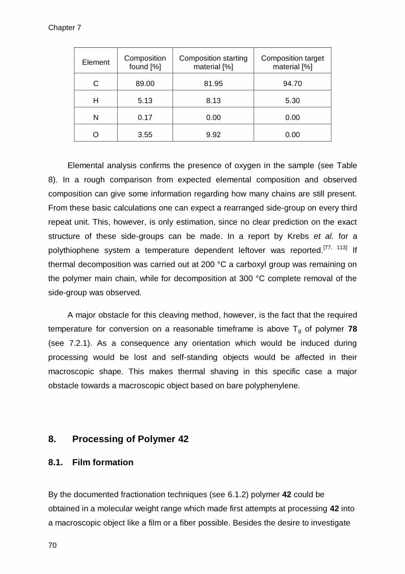
Chapter 7
70
Elemental analysis confirms the presence of oxygen in the sample (see Table
8). In a rough comparison from expected elemental composition and observed
composition can give some information regarding how many chains are still present.
From these basic calculations one can expect a rearranged side-group on every third
repeat unit. This, however, is only estimation, since no clear prediction on the exact
structure of these side-groups can be made. In a report by Krebs et al. for a
polythiophene system a temperature dependent leftover was reported.[77, 113] If
thermal decomposition was carried out at 200 °C a carboxyl group was remaining on
the polymer main chain, while for decomposition at 300 °C complete removal of the
side-group was observed.
A major obstacle for this cleaving method, however, is the fact that the required
temperature for conversion on a reasonable timeframe is above Tg of polymer 78
(see 7.2.1). As a consequence any orientation which would be induced during
processing would be lost and self-standing objects would be affected in their
macroscopic shape. This makes thermal shaving in this specific case a major
obstacle towards a macroscopic object based on bare polyphenylene.
8. Processing of Polymer 42
8.1. Film formation
By the documented fractionation techniques (see 6.1.2) polymer 42 could be
obtained in a molecular weight range which made first attempts at processing 42 into
a macroscopic object like a film or a fiber possible. Besides the desire to investigate
Element Composition
found [%] Composition starting
material [%] Composition target
material [%]
C 89.00 81.95 94.70
H 5.13 8.13 5.30
N 0.17 0.00 0.00
O 3.55 9.92 0.00

Processing of Polymer 42
71
such an object with regards to its materials properties, a crucial aspect to the shaving
protocol had to be investigated. During fiber spinning processes usually a molecular
orientation is induced, which contributes significantly to the mechanical properties of
the fiber. If the investigated shaving protocol should be successfully applied, the
induced order has to be retained during the shaving process. At first, however,
attempts were made to cast films of polymer 42 from a chloroform solution. An
example for such a film is shown in Figure 51. The haze and the light microscopy
image reveal the semi-crystalline nature of 42 obtained under these conditions.
Figure 51. Picture of a film of 42 cast by slow evaporation from CHCl3 (left), cross polarized light microscopy image of the film (right).
The DSC spectrum (Figure 52) of 42 showed an exceptionally high melting
temperature domain of 330-385°C during the first cycle and a glass transition at 200-
230 °C in the second cycle. For processing reasons a rejuvenation of the film would
be needed as processing temperatures above 385 °C are not feasible. However,
examination of the DSC sample after measurement revealed that the piece of film
could not be dissolved in CHCl3 anymore, hence a cross-linking has taken place,
despite the addition of anti-oxidants such as IrgaphosTM and IrganoxTM (0.5 % each).
This is consistent with observations from TGA (Figure 53) which indicates the start of
decomposition at 350 °C. These properties required alternative ways of processing.

Chapter 8
72
Figure 52. DSC trace of a film of 42 cast from CHCl3 with a total of 1 % of antioxidants added, measured under N2.
Figure 53. TGA curve of polymer 42. Heating rate 10 °C/min under N2.
Rapid precipitation of 42 in liquid N2 cooled MeOH and subsequent hot pressing of
the resulting white powder led to an inhomogeneous film. Despite the expected
random orientation of chains, the resulting film showed strong birefringence in some
domains(Figure 54). During hot-pressing, polymer 42 shows poor flow behavior. This
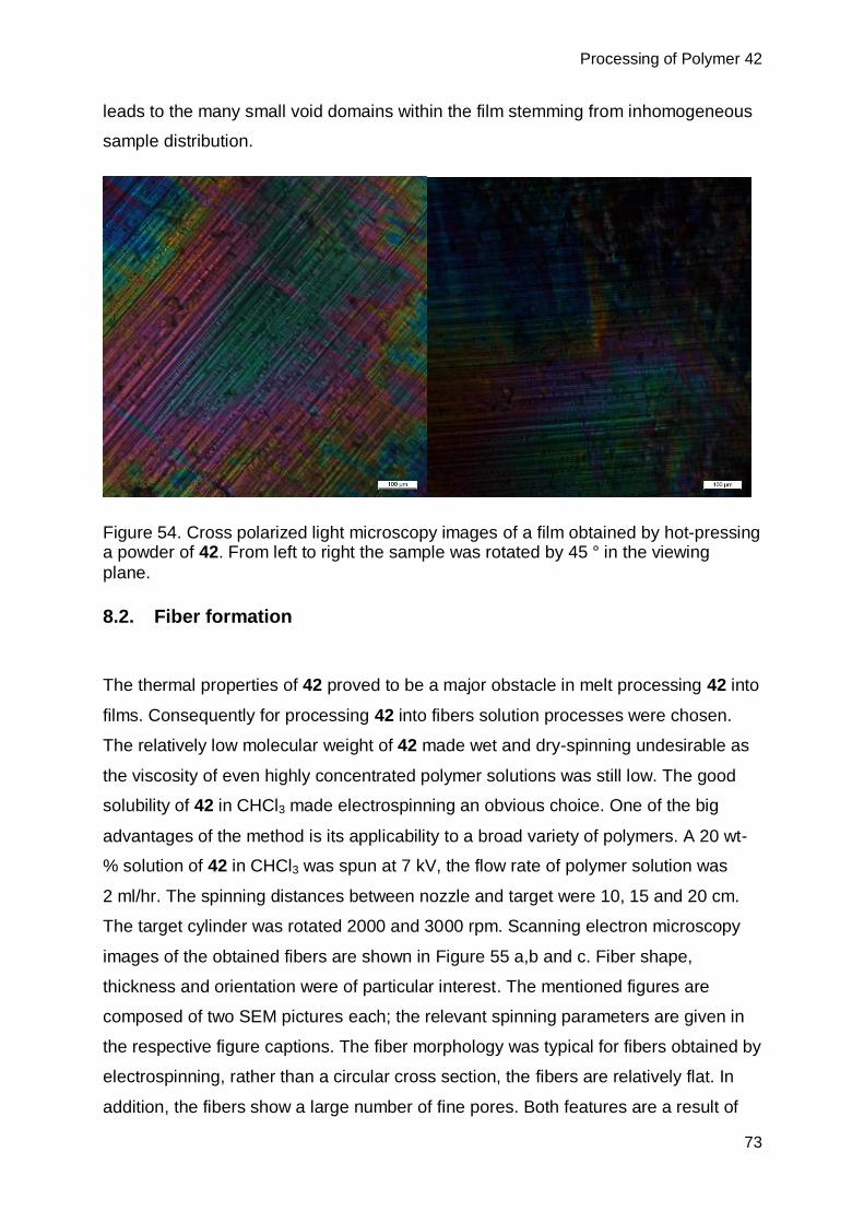
Processing of Polymer 42
73
leads to the many small void domains within the film stemming from inhomogeneous
sample distribution.
Figure 54. Cross polarized light microscopy images of a film obtained by hot-pressing a powder of 42. From left to right the sample was rotated by 45 ° in the viewing
plane.
8.2. Fiber formation
The thermal properties of 42 proved to be a major obstacle in melt processing 42 into
films. Consequently for processing 42 into fibers solution processes were chosen.
The relatively low molecular weight of 42 made wet and dry-spinning undesirable as
the viscosity of even highly concentrated polymer solutions was still low. The good
solubility of 42 in CHCl3 made electrospinning an obvious choice. One of the big
advantages of the method is its applicability to a broad variety of polymers. A 20 wt-
% solution of 42 in CHCl3 was spun at 7 kV, the flow rate of polymer solution was
2 ml/hr. The spinning distances between nozzle and target were 10, 15 and 20 cm.
The target cylinder was rotated 2000 and 3000 rpm. Scanning electron microscopy
images of the obtained fibers are shown in Figure 55 a,b and c. Fiber shape,
thickness and orientation were of particular interest. The mentioned figures are
composed of two SEM pictures each; the relevant spinning parameters are given in
the respective figure captions. The fiber morphology was typical for fibers obtained by
electrospinning, rather than a circular cross section, the fibers are relatively flat. In
addition, the fibers show a large number of fine pores. Both features are a result of

Chapter 8
74
solvent evaporation being the main driving force for fiber formation during the
electrospinning process. It is important to note that no fiber welding was observed.
The observed fiber diameter for fibers lying flat on the support was in the order of 13
µm. These are rather thick fibers as fibers of thicknesses in the tens of nanometer
range are obtainable by electrospinning.[90] A small decrease in fiber thickness with
increasing spinning distance from 10 cm to 15 cm could be observed. However, the
change was within the general polydispersity observed for the fibers within a single
set of spinning parameters. Fiber orientation is mainly important for technical
reasons. If the mechanical properties of the obtained fibers should be investigated
nicely aligned fibers facilitate the isolation of single fibers. In order to minimize fibers
intercrossing each other the collecting cylinder should be rotated at 3000 rpm or
higher (see Figure 55 c).

Processing of Polymer 42
75
Figure 55. SEM images showing fibers of polymer 42 with 15 cm (left) and 10 cm (right) spinning distance. a) The flat shape is most visible for the twisted fibers marked with arrows. b) Illustrates the fiber thickness is in the order of 13 µm and the fibers have a large number of small pores. c) Shows the effect of fiber orientation as a result of rapid rotation of the collector, which was rotated at 3000 rpm (left) and 2000 rpm (right), respectively.
Light microscopy revealed strong birefringence for the obtained fibers. Indicating that
a certain degree of order is induced during the electrospinning process. This is not
the case for all polymers. There are differing reports with regard to the presence of
birefringence in electrospun polymer fibers.[90] In some cases strong birefringence is
a)
b)
c)

Chapter 8
76
observed[114] and even quantified.[115] While other investigations report low degrees of
molecular orientation.[116],[117] In a report a lower degree of crystallinity in electrospun
fibers than in the un-spun parent material is observed. [118] This is accounted to the
fast evaporation rate of solvent. Srinivasan and Reneker observed strong
birefringence for poly(p-phenylene terephthalamid) (Kevlar®) fibers.[91] The induced
order in the electrospinning process is crucial for the mechanical properties. Any
induced order needs to be retained during the shaving process.
Figure 56. Cross polarized light microscopy images of polymer fibers of 42. Spun by
electrospinning from a CHCl3 solution. Spinning distance 15 cm, rotation speed of collector 3000 rpm.
When electrospun fibers were subjected to the shaving conditions described in
7.1.3, the fibers could not be converted as desired. The reason for this was
immediate dissolution of the fibers upon addition of the swelling agent p-xylene. To
avoid preemptive dissolution the neat fibers were doused with triflic acid for 30
seconds, then the acid was diluted with MeOH and quenched with triethylamine. The
fibers were washed multiple times with MeOH. In a solid state 13C-NMR
measurement of the treated fibers no aliphatic Carbon signals could be observed
(Figure 57).

Processing of Polymer 42
77
Figure 57. 13C CP MAS-NMR spectrum of the precursor 42 (top, blue) and acid
treated fibers (bottom, black). Spinning frequency 20 kHz.
This indicates complete removal of the side-chains to pure fibers made up of
polyphenylene 6. When investigated under cross polarized light the fibers still show
birefringence (see Figure 58). It is therefore reasonable to assume that the previously
induced order has not been majorly affected by the shaving process. Interesting to
note is the color of the fibers. Contrary to the film shaved by preemptive swelling in a
poor solvent, the color change was minor. Only a slight yellow stain could be
observed on some of the fibers while others remained white. Attempts to get more
insight into the crystalline structure by XRD-analysis failed due to insufficient contrast
obtained at maximal acceptable exposure time. Attempts to increase the contrast by
bundling the fibers more densely were unsuccessful.

Chapter 8
78
Figure 58. Cross polarized light microscopy images of the acid treated fibers, recorded at angle 0° and 45° respectively.
Fiber topology and thickness after the relatively harsh shaving process were of
particular interest. SEM analysis revealed that the number of larger pores increased
although not to a significant degree otherwise fiber topology seems to be unaffected
(see Figure 59). A slight decrease in average fiber diameter was observed. However,
the polydispersity of the diameters of treated and untreated fibers overlap to a certain
degree. 20 artificially chosen fibers were gauged for non-treated and treated fibers,
respectively. The non-treated fibers showed an average diameter of 13 ± 4 µm,
whereas for the treated fibers the average diameter was 10 ± 3 µm. Given these
findings it was not possible to exclude the presence of degraded side-chains within
the fiber structure. To exclude this, fibers were investigated by solid state 29Si- MAS
NMR (Figure 60).
Figure 59. SEM images of two artificially chosen fibers of 6. Only minor defects are
observed which are not exclusive to acid treated fibers but are also observed on fibers of 42. A slight increase in average pore size compared to untreated fibers can
be observed.
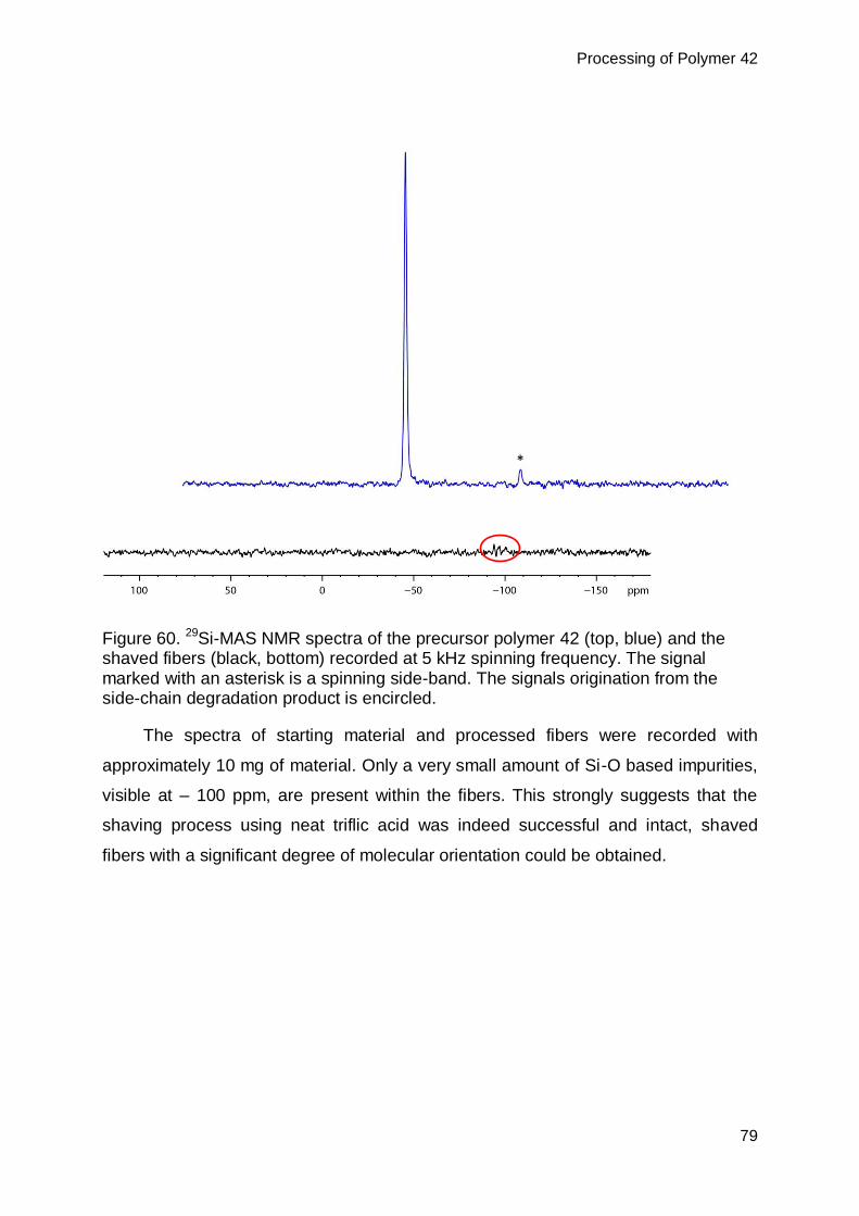
Processing of Polymer 42
79
Figure 60. 29Si-MAS NMR spectra of the precursor polymer 42 (top, blue) and the shaved fibers (black, bottom) recorded at 5 kHz spinning frequency. The signal marked with an asterisk is a spinning side-band. The signals origination from the side-chain degradation product is encircled.
The spectra of starting material and processed fibers were recorded with
approximately 10 mg of material. Only a very small amount of Si-O based impurities,
visible at – 100 ppm, are present within the fibers. This strongly suggests that the
shaving process using neat triflic acid was indeed successful and intact, shaved
fibers with a significant degree of molecular orientation could be obtained.
*
Chapter 9
80
9. Conclusion and Outlook
9.1. Conclusion
On route to obtaining an all polyphenylene based material, various monomers
were targeted in synthesis. Of these, five different monomers could be synthesized
on a multigram scale with a high degree of purity. Application of these monomers to
AA/BB-type SPC conditions lead to three different polymer structures.
One of these structures (77) showed poor solubility, but could be thoroughly
investigated with regard to end-groups present and side-reactions impeding polymer
growth.
Polymers 42 and 78 could be obtained with Mw of 50 kDa and 49 kDa,
respectively. These molecular weights were obtained in yields >90 % directly from
polymerization. If the sample was fractionated during work-up the molecular weights
for 42 a Mw of 94 kDa could be obtained. In addition to GPC analysis the polymers
were characterized by MALDI-TOF mass spectrometry, ATR-IR spectroscopy and
solution NMR spectroscopy. Employing a microwave reactor for polymer synthesis
allowed to significantly reduce reaction times, but the molecular weights obtained
were comparable or slightly lower than the ones observed for conventional heating
techniques.
The synthesized polymers carried specifically designed side-groups which were
investigated towards their removal from the main chain. Test reactions showed that
side-chain removal should be possible for both structures. The found conditions were
employed for the polymer material. In the case of 42 this was done by acid treatment,
whereas 78 was convertible by heat treatment at 375°C.
Structural analysis for the obtained products by MALDI-TOF mass
spectrometry, ATR-IR spectroscopy, solid-state NMR spectroscopy and elemental
analysis revealed that the target structure 6 could be obtained from precursor 42.
Precursor 78 led to an intermediate polymer, which was still decorated with side-
chains to a certain degree. The side-chains, however, were structurally modified with
respect to the ones present in 78. It is reasonable to assume that the acetal moiety
rearranges to form a carboxylic ester.
Experimental
81
The side-chain removal in solution of 42 was further expanded. It could be
shown that by swelling a large object (large, that is, in comparison with molecules)
almost complete removal of all side-chains is possible and core-shell anisotropy
could be avoided. Acid treated films were slightly deformed (bent) and shrunk in size,
both effects are believed to result from the significant loss in sample mass during the
‘shaving’ process. XRD analysis revealed a change in the crystal structure between
precursor and target material.
Thermal processing of 42 proofed to be a major obstacle. High Tg 200-230 °C
and high mp. 350-385 °C lead to the inability to thermally process the material. This
was due to degradation of the material at likewise temperatures as the melting
temperature.
By electrospinning from a CHCl3-solution stable fibers of 42 could be obtained.
SEM analysis revealed that the fibers are relatively flat and when lying flat on the
substrate have a thickness of 13 ± 4 nm. They show a homogeneous topology which
is dominated by a multitude of small but homogeneous pores. The fibers showed
strong birefringence under cross polarized light.
Attempts to swell these fibers lead to immediate disintegration. Treating the
fibers with neat triflic acid for 30 seconds, led to almost quantitative removal of the
side-chains, while leaving the fibers intact. This was confirmed by solid state 13C-
NMR spectroscopy. Moreover, solid state 29Si-NMR spectroscopy confirmed that only
negligible amounts of degraded side-chains are entrapped within the fibers. Only
minor reduction in fiber dimension to 10 ± 3 nm was observable using SEM. XRD
measurements of the obtained fibers before and after acid treatment, was not
possible due to the poor scattering properties and the small amounts of polymer
mass present in the beam.
Chapter 9
82
9.2. Outlook
An important feature of the AA/BB-type Suzuki polycondensation, the flexibility
in monomer design, was only exploited to a small degree in the present project. An
important part of any future work would be to exploit this feature to a much higher
degree.
Already the synthesized polymer 42 showed strong tendencies to form
crystalline phases in solution. This may be one of the reasons for the relatively poor
solubility during synthesis. It is, however, emphasized in the fibers obtained by
electrospinning. The strong birefringence observed in these fibers is a phenomenon
which is generally observed for polymers known to form liquid crystalline phases in
their given spinning solvent.[91] Predictions on the stability of the liquid crystalline
phases for rigid rod polymers have been made. It is assumed that the stability of the
liquid crystalline phases is increased with increasing aspect ratio between the length
of the stiff segments and the diameter of the molecular cross-section.[119]
Bearing in mind this theoretical prediction in combination with the synthetical
flexibility offered by AA/BB-type SPC. It would be fascinating to synthesize a series of
polymers with slightly increasing aspect ratio and observe effect of slight alterations
in chemical structure on the properties of liquid crystalline phases and the
mechanical properties of fibers from the respective polymers. Employing the
presently developed shaving procedures the precursor polymers shown in Figure 61
could be crucial stepping stones on route to this ambitious goal.
Crucial elements for success, however, would be access to polymeric material
of higher molecular weight than the one achieved in the present work. In addition to
the previously employed analysis methods, selected area electron diffraction (SAED)
could be an important tool to gain insight into the crystalline structure present in
produced fibers.

Experimental
83
Figure 61. Envisioned route to four precursor polymers AB, AD, BC and CD using only 4 monomeric building blocks.
Chapter 10
84
10. Experimental
10.1. Materials and methods
All the reactions were carried out under nitrogen by using standard Schlenk
techniques. All the reagents were purchased from commercial sources and used
without further purification unless noted. n-BuLi was used as a 1.6 M solution in
hexane. 1,3,5-Tribromobenzen was recrystallized before use. The catalyst used for
SPC was prepared according to literature procedure.[120] Column chromatography
was performed by using Fluka silica gel Si60 (particle size 40-63 µm) and Bio-Beads
S-X1.
Solution NMR spectroscopy was performed with Bruker AM at room
temperature using chloroform-d and DMSO-d6 as solvents. The signal from the
solvent was used as internal standard for chemical shift (CDCl3: 1H: δ = 7.26 ppm,
13C: δ = 77.00 ppm; DMSO-d6: 1H: δ = 2.50, 13C: δ = 39.52). 1H and 19F solid-state
NMR spectra were recorded on a Bruker Avance 700 spectrometer operating at 700
and 658.8 MHz for 1H and 19F, respectively, under magic angle spinning (MAS)
conditions with single-pulse excitation and a repetition delay of 10 s. The sample
rotation frequency was 15 kHz using 2.5 mm rotors. 13C CP/MAS spectra were
recorded on a Bruker DRX 500 and a Bruker AMX 400 spectrometer operating at
125.8 MHz for 13C under MAS conditions with 4 mm and 2.5mm rotors using a
sample rotation frequency of 8 and 20 kHz respectively, cross-polarization (CP)
employing a contact time of 1 ms and 1H high-power decoupling. 29Si solid state
NMR spectra were recorded on a Bruker AMX 400 spectrometer under MAS
conditions with single-pulse excitation and 1H high-power decoupling. A repetition
delay of 30 s was employed and the sample rotation frequency was 5 kHz using 7
mm and 4 mm rotors. Chemical shifts are expressed relative to tetramethylsilane and
CCl3F for the 1H, 13C, 29Si and 19F isotopes, respectively.
High-resolution mass spectrosmetory (HRMS) analyses were performed by the
MS-service in the laboratory of organic chemistry at ETH Zurich using an electron-
ionization (EI) MS spectrometer (Micromass AutoSpec-Ultima) and en electron spray
ionization (ESI) MS spectrometer (Bruker maXis) with a quadrupol-time-of-flight
tandem analyzer (Q-Tof). MALDI-TOF mass spectra were recorded using a Bruker

Experimental
85
UltraFlex II MALDI-TOF mass spectrometer (Bremen, Germany) equipped with a N2
smartbeam laser (λ = 337 nm, 150 µJ, 3 ns) operating at a pulse rate of 100 Hz. For
MALDI-TOF MS analyses, the ions were accelerated with pulsed ion extraction (PIE)
by a voltage of 25 kV. The analyzer was operated in reflection mode unless
otherwise stated, and the ions were detected using a microchannel plate detector. A
total of 500-1000 shots were accumulated for each mass spectrum. Samples were
prepared with a solvent-free method[121] in which an analyte, matrix and
AgOTf/NaOTf were mixed by milling at room temperature to be in the molar ratio of
1/10/1 for all samples except for 6 which was milled in a ratio of 1/500/50. The matrix
used for all samples was trans-2-[3-(4-tert-butylphenyl)-2-methyl-2-
propenylidene]malononitrile (DCTB) except for 6 where tetracyanoquinodimethane
(TCNQ) was used. Calibration was carried out during each measurement on
surrounding spots using peptide calibration standard II (Bruker) dissolved in 0.1%
trifluoroacetic acid (TFA) with α-cyano-4-hydroxicinnamic acid (HCCA) in a mixed
solvent of CH3CN/0.1% TFA 1:2.
Elemental analyses were performed by the Micro-Laboratory in the laboratory of
organic chemistry at ETH Zurich using LECO CHN-900 (infrared detection for C and
H), combustion carried out at 1000 ºC.
Analytical GPC measurements were performed using a Viscotek GPC-System
with chloroform eluent, equipped with a pump and a degasser (GPCmax VE2001,
flow rate 1.0 ml/min), a detector module (Viscotek 302 TDA) and two columns (1 ×
PLGel Mix-C and 1 × PLGel Mix-B, 7.5 × 300 mm for each). Calibration was
performed with polystyrene standards (Polymer laboratories) in the range of Mp 1480
to 4340000. Prior to injection, the sample solution was filtered through a sintered
stainless steel filter (pore size 2 µm and 0.45 µm).
Infrared spectroscopic analyses were carried out using attenuated total
reflection (ATR) - Fourier transform infrared (FTIR) spectrometer (Bruker Optics
Alpha system with a built-in diamond ATR). OPUS 6 from Bruker was used as
software. The data represent the average of 24 scans in the wavenumber range
between 4000 – 500 cm-1 at a resolution of 1.42 cm-1.
TGA was measured on a TGA Q500 (TA Instruments, USA) under N2
atmosphere in a platinum pan. Thermal stress tests were carried out isothermally

Chapter 10
86
with a heating ramp of 20 °C/min. Overview measurements were done at a heating
rate of 10 °C/min. The sample mass was between 2-10 mg.
DSC was measured on a DSC Q1000 (TA Instrument, USA) and a DSC 822e
(Mettler Toledo, Switzerland) using aluminum pans. Heating and cooling rate were 10
°C/min.
Films were casted from a chloroform solution using 10-15 wt % of polymer. All
solutions were heated to 50 °C while stirring for 6 hours prior to film casting. Films
were cast into petri-dishes, after filtration through a 0.45 µm mesh size PTFE filter.
The closed petri-dishes were left to stand until solvent evaporation was complete.
Pressed films were cast in a Rondol Technology hot press at 210 °C between
two thin aluminum plates. To the samples 0.5 % of Irgaphos and 0.5 % of Irganox
were added as stabilizers to prevent oxidation.
Fiber spinning was done on an in house assembled electrospinning device. An
AL-1000 syringe pump was used to pump the solution to a flat tipped steel cannula.
A DC high voltage supply (Glassmann high voltage Inc., USA) was operated at 7kV
and 5 mA. A hollow aluminum cylinder (diameter: 80 mm, wall thickness: 5 mm)
served as collector, which was rotated at 2000-3000 rpm.
Light microscopy images were measured on a Leica DMRX instrument using a
Leica DFC480 camera in transmission mode.
SEM images were recorded on a Zeiss SUPRA 50 VP and a Zeiss LEO Gemini
1560 (Zeiss, Germany) using secondary electron detection. Accelerating voltage
was 5 kV, aperture width was 30.00 µm and 28.80 µm respectively. A SCD500 and
SCD050 sputter coater (Bal-Tec, Liechtenstein) was used to deposit a 10 nm
platinum layer (50 mA, 60 s) on the samples.
Powder XRD measurements were carried out on a XCalibur single-crystal X-ray
diffractometer (Oxford Diffraction, UK) using an Onyx CCD detector. The wavelength
used was Mo-Kα (λ = 0.71073 Å) using a graphite monochromator. Data evaluation
was done with FIT2D.[122]

Experimental
87
10.2. 1,4-di(1,3,2-dioxaborinan-2-yl)benzene[123] (32)
A 2 L round bottom flask was charged with 27.22 g (164.2 mmol) of 1,4 -
phenylenediboronic acid (15) and 25.62 g (336.7 mmol, 2.05 eq) of propan-1,3-diol.
The starting materials were dissolved in 1000 ml toluene and the reaction was heated
at a Dean-Stark apparatus overnight. The solvent was removed in vacuum and the
resulting solid was redissolved in Diethylether. Hot filtration and subsequent
crystallization (2x) yielded the desired product as colorless crystals (29.42 g, 72.9 %).
1H-NMR(CDCl3, 300.23 MHz): δ = 7.77 (s, 4 H, arom. H), 4.19 (t, J = 5.48 Hz, 8
H, O-CH2), 2.08 (quin, J = 5.48 Hz, 4 H, CH2) ppm.
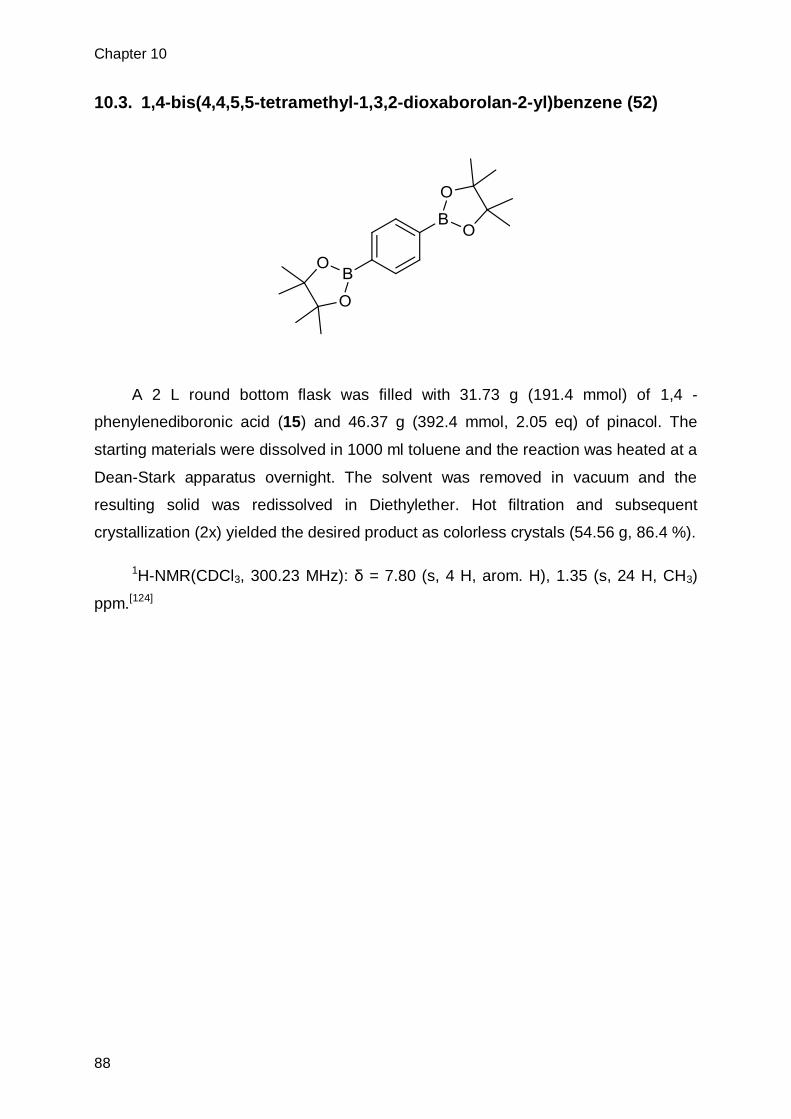
Chapter 10
88
10.3. 1,4-bis(4,4,5,5-tetramethyl-1,3,2-dioxaborolan-2-yl)benzene (52)
A 2 L round bottom flask was filled with 31.73 g (191.4 mmol) of 1,4 -
phenylenediboronic acid (15) and 46.37 g (392.4 mmol, 2.05 eq) of pinacol. The
starting materials were dissolved in 1000 ml toluene and the reaction was heated at a
Dean-Stark apparatus overnight. The solvent was removed in vacuum and the
resulting solid was redissolved in Diethylether. Hot filtration and subsequent
crystallization (2x) yielded the desired product as colorless crystals (54.56 g, 86.4 %).
1H-NMR(CDCl3, 300.23 MHz): δ = 7.80 (s, 4 H, arom. H), 1.35 (s, 24 H, CH3)
ppm.[124]
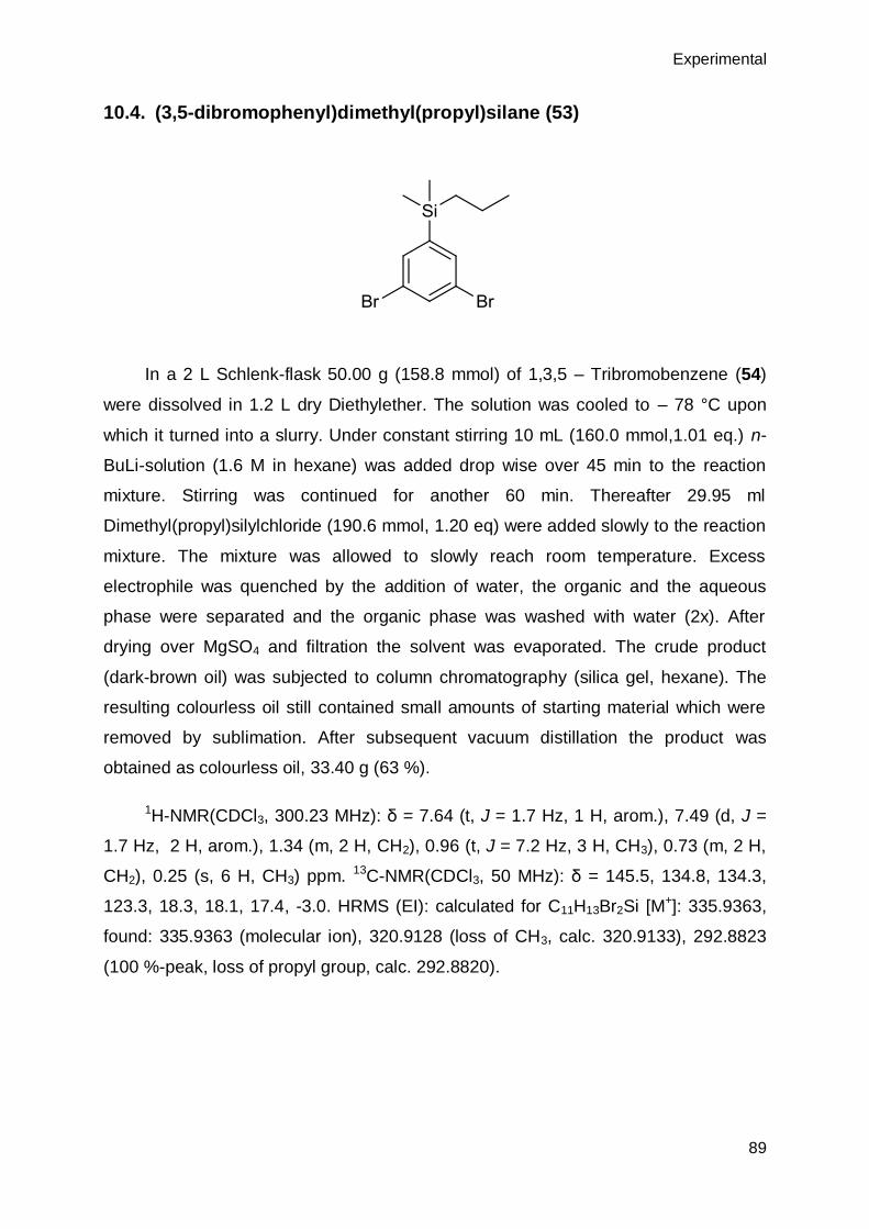
Experimental
89
10.4. (3,5-dibromophenyl)dimethyl(propyl)silane (53)
In a 2 L Schlenk-flask 50.00 g (158.8 mmol) of 1,3,5 – Tribromobenzene (54)
were dissolved in 1.2 L dry Diethylether. The solution was cooled to – 78 °C upon
which it turned into a slurry. Under constant stirring 10 mL (160.0 mmol,1.01 eq.) n-
BuLi-solution (1.6 M in hexane) was added drop wise over 45 min to the reaction
mixture. Stirring was continued for another 60 min. Thereafter 29.95 ml
Dimethyl(propyl)silylchloride (190.6 mmol, 1.20 eq) were added slowly to the reaction
mixture. The mixture was allowed to slowly reach room temperature. Excess
electrophile was quenched by the addition of water, the organic and the aqueous
phase were separated and the organic phase was washed with water (2x). After
drying over MgSO4 and filtration the solvent was evaporated. The crude product
(dark-brown oil) was subjected to column chromatography (silica gel, hexane). The
resulting colourless oil still contained small amounts of starting material which were
removed by sublimation. After subsequent vacuum distillation the product was
obtained as colourless oil, 33.40 g (63 %).
1H-NMR(CDCl3, 300.23 MHz): δ = 7.64 (t, J = 1.7 Hz, 1 H, arom.), 7.49 (d, J =
1.7 Hz, 2 H, arom.), 1.34 (m, 2 H, CH2), 0.96 (t, J = 7.2 Hz, 3 H, CH3), 0.73 (m, 2 H,
CH2), 0.25 (s, 6 H, CH3) ppm. 13C-NMR(CDCl3, 50 MHz): δ = 145.5, 134.8, 134.3,
123.3, 18.3, 18.1, 17.4, -3.0. HRMS (EI): calculated for C11H13Br2Si [M+]: 335.9363,
found: 335.9363 (molecular ion), 320.9128 (loss of CH3, calc. 320.9133), 292.8823
(100 %-peak, loss of propyl group, calc. 292.8820).

Chapter 10
90
10.5. ethyl 4-amino-3,5-dibromobenzoate[98] (58)
To a 2 l round bottom flask 93.0g (563 mmol) of 4-amino-ethylbenzoate (57)
was dissolved in 1.25 l of AcOH. The flask was fitted with a dropping funnel through
which, under constant stirring, 60 ml (1.17 mol, 2.07 eq) of Br2 in 150 ml AcOH was
added over 2.5 h. The reaction was heated to 85 °C and the temperature was
maintained for 1.5 h. After the reaction was cooled to room temperature, it was
poured on ice and left to stand overnight. The resulting suspension was filtered and
washed with water. The resulting light yellow solid was recrystallized from MeOH.
Affording 156 g (86 %) of the pure product. 1H-NMR (300.23 MHz, CDCl3) δ/ppm:
8.07 (s, 2 H, arom. H), 4.98 (s broad, 2 H, NH2), 4.33 (q, J = 7.1 Hz, 2 H, CH2), 1.37
(t, J = 7.0 Hz, 3 H, CH3) ppm.

Experimental
91
10.6. ethyl 3,5-dibromobenzoate[98] (59)
156 g (0.483 mol) of ethyl 4-amino-3,5-dibromobenzoate (58) was dissolved in
a 3-l round bottom flask with 1.3 l of EtOH. After heating to 50 °C 200 ml of
concentrated H2SO4 (3.62 mol, 7.5 eq) was added dropwise. The reaction was
heated to 70°C and 101 g (1.46 mol, 3 eq) of NaNO2 in 210 ml water was added
dropwise. During the addition the solution turned brown. After 16 h heating was
stopped and the reaction was allowed to cool to room temperature. The reaction was
poured on ice and filtered. The residue was washed with water and recrystallized
from Isopropanol (2x). Affording 49.5 g (33 %) of the product as colorless crystals.
1H-NMR (300.23 MHz, CDCl3) δ = 8.10 (d, J = 1.77 Hz, 2 H, arom. H), 7.84 (t, J =
1.74 Hz, 1 H, arom. H), 4.39 (q, J = 7.12 Hz, 2 H, CH2), 1.40 (t, J = 7.09 Hz, 3 H,
CH3) ppm.
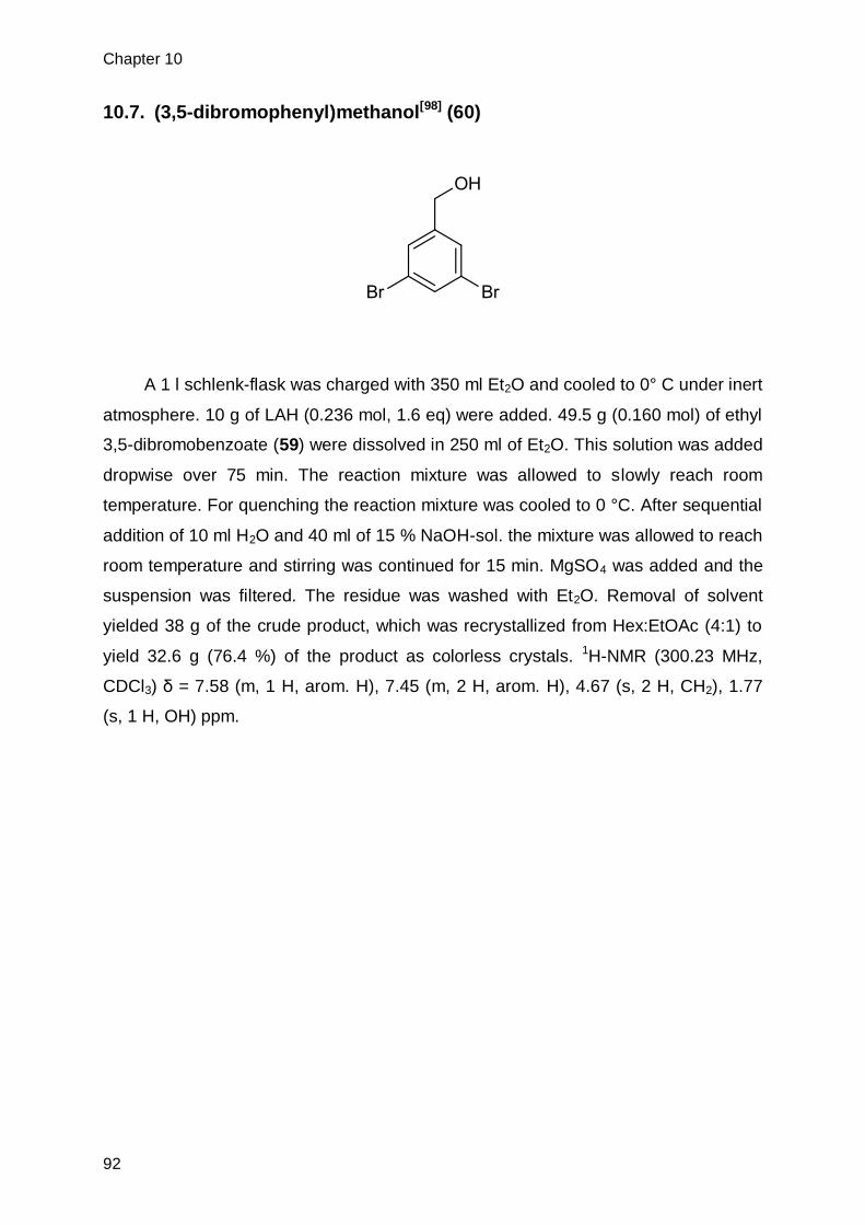
Chapter 10
92
10.7. (3,5-dibromophenyl)methanol[98] (60)
A 1 l schlenk-flask was charged with 350 ml Et2O and cooled to 0° C under inert
atmosphere. 10 g of LAH (0.236 mol, 1.6 eq) were added. 49.5 g (0.160 mol) of ethyl
3,5-dibromobenzoate (59) were dissolved in 250 ml of Et2O. This solution was added
dropwise over 75 min. The reaction mixture was allowed to slowly reach room
temperature. For quenching the reaction mixture was cooled to 0 °C. After sequential
addition of 10 ml H2O and 40 ml of 15 % NaOH-sol. the mixture was allowed to reach
room temperature and stirring was continued for 15 min. MgSO4 was added and the
suspension was filtered. The residue was washed with Et2O. Removal of solvent
yielded 38 g of the crude product, which was recrystallized from Hex:EtOAc (4:1) to
yield 32.6 g (76.4 %) of the product as colorless crystals. 1H-NMR (300.23 MHz,
CDCl3) δ = 7.58 (m, 1 H, arom. H), 7.45 (m, 2 H, arom. H), 4.67 (s, 2 H, CH2), 1.77
(s, 1 H, OH) ppm.

Experimental
93
10.8. 2-((3,5-dibromobenzyl)oxy)tetrahydro-2H-pyran[27] (61)
A 500 ml schlenk-flask was charged with 24.3 g (91.4 mmol) (3,5-
dibromophenyl)methanol (60) in 300 ml dry DCM and cooled to 0°C. 12.5 ml of
Dihydropyrane (137 mmol, 1.5 eq) were added in addition to 175 mg of p-TsOH·H2O
(0.9 mmol, 1 mol %). The reaction was allowed to reach room temperature overnight.
The reaction was quenched by addition of 1 ml NEt3. The solvent was removed under
reduced pressure. Column chromatography (Silica gel, Hex:DCM 3:1, Hex:DCM 1:1,
DCM (+0.5 % of NEt3 for all elution mixtures)) afforded 25.8 g (80.6 %) of the product
as a colorless oil. 1H-NMR (300.23 MHz, CDCl3) δ = 7.57 (m, 1 H, arom. H), 7.44 (m,
2 H, arom. H), 4.67 (d, J= 12.7 Hz, 1 H, CH2) and 4.46 (d, J= 12.7 Hz, 1 H, arom.-
CH2-O), 4.68-4.70 (m, 1 H, CH), 3.83-3.90 (m, 1 H, O-CH2) and 3.52-3.59 (m, 1 H, O-
CH2), 1.50-1.93 (m, 6 H, CH2) ppm.

Chapter 10
94
10.9. 3,5 – Dibromobenzaldehyde[96] (55)
In a 1 L Schlenk-flask 20 g (63.5 mmol) of 1,3,5 – Tribromobenzene (54) were
dissolved in 500 ml dry Diethylether. The solution was cooled to – 78°C upon which it
turned into a slurry. Under constant stirring 42 mL (66.7 mmol,1.05 eq.) n-BuLi-
solution (1.6 M in hexane) was added drop wise over 35 min to the reaction mixture.
Stirring was continued for another 45 min. Thereafter 15 ml dry DMF (194 mmol, 3.1
eq) were added slowly to the reaction mixture. After 1 h stirring the reaction was
quenched with 160 ml of 10 % HCl-solution. After reaching room temperature, the
organic and the aqueous phase were separated and the organic phase was washed
with water (2x). After drying over MgSO4 and filtration the solvent was evaporated.
The crude product (dark-brown solid) was recrystallized from Et2O/hex which
afforded 12.21 g (73 %) of the pure product as dark brown needles.
1H-NMR(CDCl3, 300.23 MHz): δ = 9.93 (s, 1 H, aldehyde H), 7.95 (m, 3 H,
arom.) ppm. 13C-NMR(CDCl3, 50 MHz): δ = 189.3, 139.7, 139.0, 131.4, 124.1 ppm.

Experimental
95
10.10. 5-Butyl-2-(3,5-dibromophenyl)-5-ethyl-1,3-dioxane (56)
In a 250 ml Schlenk flask, charged with 120 ml of toluene, 8.00 g (30.31 mmol)
of 3,5 – dibromobenzaldehyde (55) and 5.10 g (31.83 mmol, 1.05 eq) of 2-Butyl-2-
ethylpropane-1,3-diol were brought into solution. After the addition of 560 mg (2.94
mmol, 0.097 eq) 4-Methylbenzenesulfonic acid monohydrate the vessel was fitted
with a Dean-Stark-apparatus and the reaction was heated to reflux over night. The
reaction was quenched by the addition of 2 ml NEt3. After removal of solvent under
reduced pressure the residue was purified by silica gel chromatography (10:1
hexane/ethylacetate + 1 % NEt3). The resulting yellow oil was further purified by
vacuum distillation (0.02 mbar, 185 °C) which afforded 9.45 g (77 %) of the pure
product as colourless oil.
1H – NMR (CDCl3, 30.23 MHz): δ = 7.63 (s, 1H, arom.), 7.58 (s, 2 H, arom.),
5.31 (s, 1 H, -CH (- O-)2), 3.94 (d, J = 11.1 Hz, O-CH2-), 3.62 (dd, J = 11.7, 4.5 Hz,
O-CH2-), 1.85 - 1.65 (m, 2 H, alkyl), 1.45 – 1.00 (m, 6 H, alkyl), 1.00 – 0.75 (m, 6 H,
alkyl) ppm. 13C-NMR(CDCl3, 75.5 MHz): δ = 142.3, 134.2, 128.3, 122.8, 99.8, 75.3
and 75.1, 34.9 and 34.8, 31.7 and 30.1, 25.4 and 25.0, 24.3 and 23.6, 23.5 and 23.3,
14.3 and 14.0, 7.7 and 6.8 ppm. HRMS(EI): [M+] calc: 403.9981 amu, found:
403.9981 amu. other signals (amu): 83.0852, 70.0776 (100 %), 55.0565, 41.0463
(alkyl fragmentation series); 171.1381 (acetal moiety, calc. 171.1385).
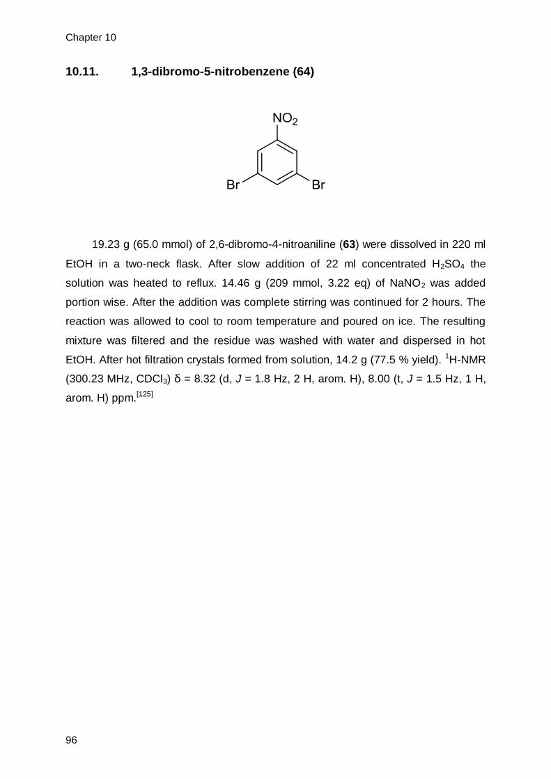
Chapter 10
96
10.11. 1,3-dibromo-5-nitrobenzene (64)
19.23 g (65.0 mmol) of 2,6-dibromo-4-nitroaniline (63) were dissolved in 220 ml
EtOH in a two-neck flask. After slow addition of 22 ml concentrated H2SO4 the
solution was heated to reflux. 14.46 g (209 mmol, 3.22 eq) of NaNO2 was added
portion wise. After the addition was complete stirring was continued for 2 hours. The
reaction was allowed to cool to room temperature and poured on ice. The resulting
mixture was filtered and the residue was washed with water and dispersed in hot
EtOH. After hot filtration crystals formed from solution, 14.2 g (77.5 % yield). 1H-NMR
(300.23 MHz, CDCl3) δ = 8.32 (d, J = 1.8 Hz, 2 H, arom. H), 8.00 (t, J = 1.5 Hz, 1 H,
arom. H) ppm.[125]

Experimental
97
10.12. 3,5-dibromoaniline (65)
In a 100 ml round bottom flask 2.41 g (8.58 mmol) of 1,3-dibromo-5-
nitrobenzene (64) was dissolved in 40 ml THF/EtOH (1:1). While stirring 10.0 g (44.3
mmol, 5.17 eq) of SnCl2 · 2 H2O was added slowly and the reaction was stirred at
room temperature for 20 hours. The solvent was evaporated and the residue was
dispersed in in dilute NaOH (aq.). Extraction with Et2O, subsequent drying over
Na2SO4 and removal of solvent yielded 1.82 g (84.7 %) of the pure product. 1H-NMR
(300.23 MHz, CDCl3) δ = 7.02 (m, 1 H, arom. H), 6.74 (d, J = 1.5 Hz, 2 H, arom. H),
3.76 (s, 2 H, NH2) ppm.[126]

Chapter 10
98
10.13. tert-butyl (3,5-dibromophenyl)carbamate (62)
In a 250 ml round bottom flask 4.2 g (16.7 mmol) of 3,5 –Dibromoaniline (65)
were dissolved in 80 ml of toluene. After addition of 20 ml (87.0 mmol, 5.2 eq) Boc2O
and 10 ml (57.8 mmol, 3.5 eq) of DIEA the solution was heated to reflux for 24 h.
Removal of solvent and recrystallization from Et2O afforded 1.44 g (24.4 %) of the
pure product as white needles. 1H-NMR (CDCl3, 300.23 MHz) δ = 7.61 (t, J = 1.60
Hz, 1 H, arom. H), 7.27 (d, J = 1.67 Hz, 2 H, arom. H), 1.45 (s, 9 H, CH3) ppm. 13C-
NMR (CDCl3, 75.5 MHz) δ = 151.2, 141.3, 133.3, 130.4, 122.3, 83.8, 28.1 ppm.
HRMS (ESI): [M+Na]+ calculated: 373.9185 amu, found: 373.9189 amu.

Experimental
99
10.14. 4,4'-dibromo-2,2'-dinitro-1,1'-biphenyl (67)
In a 250 ml round bottom flask 24 g (85.4 mmol) of 1,4-Dibromo-2-nitrobenzene
(66) was dissolved in 110 ml Dimethylformamide. 12 g (188.9 mmol, 2.2 eq) copper
powder was added portion wise while stirring. After the addition the suspension was
heated to 125 °C for 3 h. After removal of solvent the resulting solid was dispersed in
600 ml benzene, the suspension was filtered through celite. Removal of solvent at
reduced pressure yielded the crude product. After recrystallization from isopropanol
the product was obtained as yellow crystals, 12.08 g (70 % yield). 1H-NMR (300.23
MHz, CDCl3) δ = 8.38 (d, J = 1.9 Hz, 2 H), 7.83 (dd, J1= 8.2 Hz, J2 = 1.9 Hz, 2 H),
7.16 (d, J = 8.2 Hz, 2 H) ppm.[102]
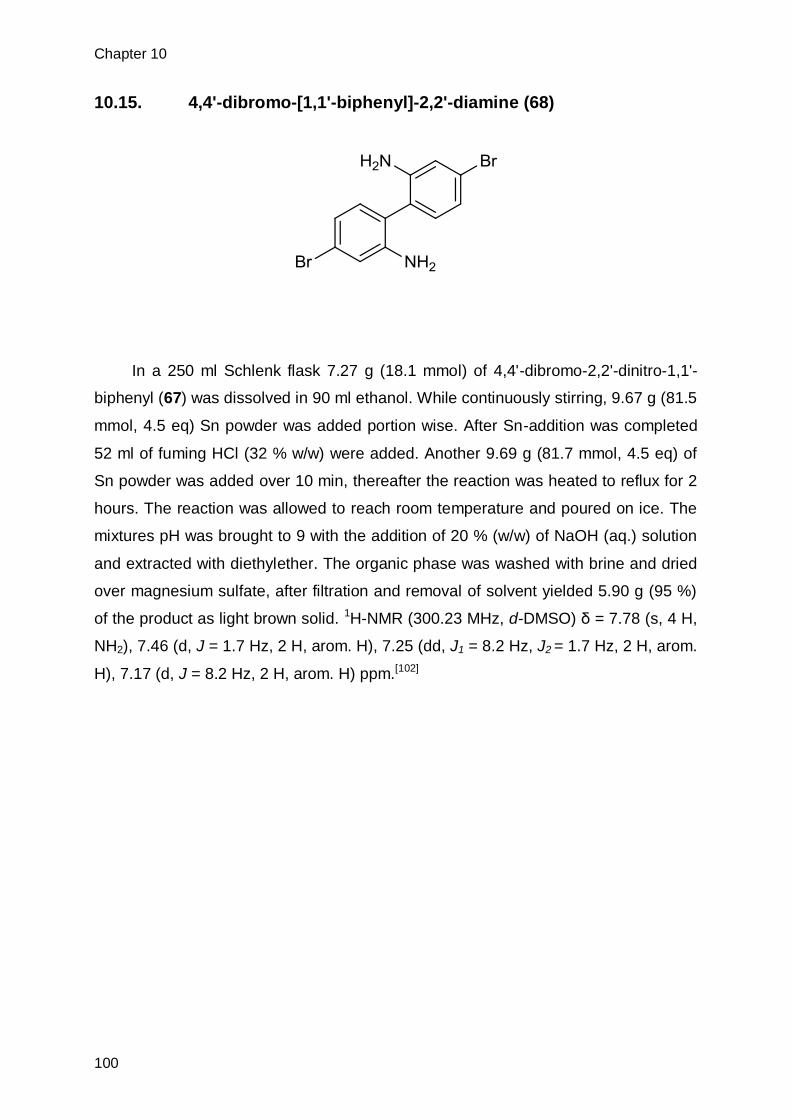
Chapter 10
100
10.15. 4,4'-dibromo-[1,1'-biphenyl]-2,2'-diamine (68)
In a 250 ml Schlenk flask 7.27 g (18.1 mmol) of 4,4'-dibromo-2,2'-dinitro-1,1'-
biphenyl (67) was dissolved in 90 ml ethanol. While continuously stirring, 9.67 g (81.5
mmol, 4.5 eq) Sn powder was added portion wise. After Sn-addition was completed
52 ml of fuming HCl (32 % w/w) were added. Another 9.69 g (81.7 mmol, 4.5 eq) of
Sn powder was added over 10 min, thereafter the reaction was heated to reflux for 2
hours. The reaction was allowed to reach room temperature and poured on ice. The
mixtures pH was brought to 9 with the addition of 20 % (w/w) of NaOH (aq.) solution
and extracted with diethylether. The organic phase was washed with brine and dried
over magnesium sulfate, after filtration and removal of solvent yielded 5.90 g (95 %)
of the product as light brown solid. 1H-NMR (300.23 MHz, d-DMSO) δ = 7.78 (s, 4 H,
NH2), 7.46 (d, J = 1.7 Hz, 2 H, arom. H), 7.25 (dd, J1 = 8.2 Hz, J2 = 1.7 Hz, 2 H, arom.
H), 7.17 (d, J = 8.2 Hz, 2 H, arom. H) ppm.[102]

Experimental
101
10.16. 4,4'-dibromo-2,2'-diiodo-1,1'-biphenyl (69)
In a 1 l schlenk flask 10 g (29.2 mmol) of 4,4'-dibromo-[1,1'-biphenyl]-2,2'-
diamine (68) were dissolved in 150 ml of 9 % H2SO4. The mixture was cooled to 0 °C
and 10.08 g (146 mmol, 5 eq.) in 50 ml of water were added slowly under vigorous
stirring. After 45 min, 53.82 g (324 mmol, 11 eq) of KI in 100 ml of water was added
and the reaction was allowed to reach room temperature within 4 h. An excess of
Na2S2O3 solution was added to quench the reaction. The mixture was extracted with
hexane:DCM (9:1), the organic phase was dried with MgSO4 and solvent was
removed. The residue was dissolved in CHCl3 and the solution was concentrated.
Crystals formed which were removed by filtration (side-product, mono-
transformation), the mother liquor was concentrated completely. Column
chromatography (silica gel, hexane) gave 3.70 g (22.5 %) of the product as light
yellow solid. 1H-NMR (CDCl3, 300.23 MHz) δ = 8.10 (d, J = 1.70 Hz, 2 H, arom. H),
7.56 (dd, J1 = 1.76 Hz, J2 = 8.16 Hz, 2 H, arom. H), 7.03 (d, J = 8.16 Hz, 2 H, arom.
H) ppm. 13C-NMR (CDCl3, 75.5 MHz) δ = 146.9, 141.1, 131.5, 130.9, 122.6, 100.0
ppm. HRMS (EI): [M]+ calculated: 561.6926 amu found: 561.6948 amu, [M - I]+ calc:
434.7881 amu, found: 434.7867 amu, [M – I -Br]+.calc: 355.8698 amu, found:
355.8683 amu, [M - 2 I]+ calc: 307.8836 amu, found: 307.8842 amu, [M - 2 I - Br]+
calc: 228.9653 amu, found: 228.9651 amu, [M - 2 I – 2 Br]+ calc: 150.0470 amu,
found: 150.0465 amu.

Chapter 10
102
10.17. di-tert-butyl (4,4'-dibromo-[1,1'-biphenyl]-2,2'-diyl)dicarbamate
In a 100 ml round bottom flask 1.50 g (4.39 mmol) of 4,4'-dibromo-[1,1'-
biphenyl]-2,2'-diamine (68) was dissolved in 20 ml of THF and 3.4 ml (18.86 mmol,
4.3 eq) of DIEA was added and the solution was stirred for 15 min. After addition of
2.3 ml (9.65 mmol, 2.2 eq) of Boc-anhydride the solution was heated to reflux. The
reaction course was followed by TLC after 24 and 48 hours respectively an additional
2 ml (8.4 mmol, 2 eq) anhydride was added. After 72 hours TLC indicated complete
consumption of starting material. Water was added and the mixture was extracted
with ethylacetate, drying over magnesium sulfate and removal of solvent under
reduced pressure afforded the crude product. Purification by column chromatography
(silica gel, hexane/CH2Cl2) yielded 1.14 g (48 %) of the pure product. 1H-NMR
(300.23 MHz, CDCl3) δ = 8.50 (d, J = 1.6 Hz, 2 H, arom. H), 7.27 (dd, J1 = 1.8 Hz, J2
= 8.1 Hz, 2 H, arom. H), 6.70 (d, J = 8.0 Hz, 2 H, arom. H), 6.14 (s, 2 H, NH), 1.46 (s,
9 H, CH3) ppm. 13C-NMR (75.5 MHz, CDCl3) δ = 152.24, 137.71, 131.50, 126.39,
123.82, 123.54, 122.60, 81.58, 28.20 ppm. ESI-MS: calc. 543.03 amu, found: 543.03
amu.

Experimental
103
10.18. 4,4'-dibromo-2-nitro-1,1'-biphenyl (73)
In a 500 ml 3-neck flask a solution of 20 g (64.1mmol) 4,4’-Dibromo-1,1’-
biphenyl (72) in AcOH was heated to 100 °C. A solution of 92.5 ml (2.22 mol, 34.7
eq) fuming HNO3 and 7 ml water was added drop-wise to the reaction mixture upon
which a precipitate formed. Heating for 30 min resulted in the precipitate dissolving
again. Upon complete dissolution, heating was stopped. After the reaction mixture
cooled down, it was poured into 1.5 l of 0.6 M NaOH-solution. Filtration and washing
with water afforded the crude product as a yellow solid, which could be recrystallized
from EtOH. 15.18 g (42.5 mmol, 66 %) of the pure product was obtained as yellow
crystals. 1H-NMR (CDCl3, 300.23 MHz) δ = 8.00 (d, J = 1.80 Hz, 1 H, arom.), 7.73
(dd, J1 = 1.91 Hz, J2 = 8.24 Hz, 1 H, arom.), 7.53 (d, J = 8.37 Hz, 1 H, arom.), 7.26
(d, J = 8.20 Hz, 2 H, arom.), 7.13 (d, J = 8.35 Hz, 2 H, arom.) ppm.[103] melting-point:
117-121 °C. Lit: 124 °C.[127]

Chapter 10
104
10.19. 4,4'-dibromo-[1,1'-biphenyl]-2-amine (74)
In a 50 ml round bottom flask 0.50 g (1.4 mmol) of 4,4’-dibromo-2-nitro-1,1’-
biphenyl (73) were suspended in10 ml of EtOH. 2.6 ml (86 mmol, 61 eq) of
concentrated HCl (aq.) was added slowly. After portion-wise addition of 0.33 g (2.8
mmol, 2 eq) of Sn(s) the reaction was heated to 85 °C upon which complete
dissolution occurred, heating was continued overnight. The reaction was quenched
by the addition of NaOH (aq.) to a pH ~ 8. The mixture was extracted with DCM,
dried over NaSO4 and filtered. Removal of solvent under reduced pressure yielded a
light brown solid, 0.44 g (96 %). 1H-NMR (CDCl3, 300.23 MHz) δ = 7.55-7.57 (m, 2 H,
arom. H), 7.28 – 7.31 (m, 2 H, arom. H), 6.94 – 7.02 (m, 3 H, arom. H), 4.61 (s
(broad), 2 H, NH2) ppm.[104]

Experimental
105
10.20. 4,4'-dibromo-2-iodo-1,1'-biphenyl (75)
In a 2 l flask 19.0 g (58.1 mmol) of 4,4'-dibromo-[1,1'-biphenyl]-2-amine (74)
was suspended in 500 ml of water and 100 ml of concentrated H2SO4. The mixture
was cooled bellow 5 °C and slowly 5 g (72.6 mmol, 1.25 eq) of NaNO2 in 50 ml of
water was added. Stirring was continued for 1 h. 20 g (120 mmol, 2.1 eq) of KI in 100
ml of water was added. The reaction was allowed to slowly reach room temperature.
The mixture was extracted with DCM. The organic phase was washed with Na2S2O3
(aq.), NaOH (aq.) and dried over MgSO4. Removal of solvent gave the crude product
as dark brown oil. Column chromatography (silica gel, hexane) and subsequent
recrystallization from hexane yielded the product as light yellow solid (7.01 g, 27.5
%). 1H-NMR (CDCl3, 300.23 MHz) δ = 8.10 (d, J = 1.73 Hz, 1 H, arom. H (2)), 7.50-
7.58 (m, 3 H, arom. H (5, 2’, 6’)), 7.16-7.20 (m, 2 H, arom. H (3’, 5’)), 7.13 (d, J = 8.21
Hz, arom. H (6)) ppm. 13C-NMR (CDCl3, 75.5 MHz) δ = 144.5, 142.0, 141.6, 131.5,
131.4, 130.9, 130.8, 122.4, 122.1, 98.9 ppm. HRMS (EI): [M]+ calculated: 435.7954
amu, found: 435.7949 amu; other signals: [M]+ - Br – I calculated: 229.9731 amu,
found: 229.9725 amu; [M]+ - halogens calculated: 151.0548 amu, found: 141.0543
amu.

Chapter 10
106
10.21. Suzuki-Polycondensation procedures
Standart SPC procedure for the synthesis of polymer 42
To a 1 l schlenk-flask 7.01642 g (20.8736 mmol) of monomer 53 and 6.88901 g
(20.8736 mmol, 1.00000 eq) of monomer 52 were added. All weighing-vessels were
carefully rinsed repeatedly with THF to ensure complete transfer. The total amount of
THF used was 500 ml, which was complemented with 100 ml of water. To this
solution 16.8 g (0.2 mol, 10 eq) of NaHCO3 was added. Subsequently the mixture
was degased. To the degased reaction mixture 120 mg (0.18 mmol, 0.58 mol-%) of
catalyst were added in a solution of degased THF. The reaction mixture was heated
to 72 °C for 96 h. After cooling toluene was added to the mixture and the layers were
separated. The organic phase was washed with water (2x). Thereafter the
suspension was heated to 150°C in a pressure vessel for at least 6 h. After cooling
insoluble parts were filtered off and collected separately. To the resulting solution a
NaCN solution (basic pH by NaHCO3) was added and the mixture was stirred
vigorously for a minimum of 6 h. The inorganic phase was separated and the organic
phase was washed with dilute NaHCO3 solution (2x) and water (2x), concentrated
and precipitated from cold MeOH to afford 4.99 g (94.5 %) of polymer 42 as a white
powder.

Experimental
107
Microwave assisted SPC procedure for the synthesis of polymer 42
25 ml of a 0.028 M stock solution (0.7 mmol), containing monomer 52 and
monomer 53 in equimolar amounts, was added with 10 ml of H2O to a degasing
vessel. The reaction solution was subsequently degased by repeated freeze-pump-
thaw cycles (3x). The microwave reaction vessel was charged with 0.375 g (4.5
mmol, 6.4 eq.) of NaHCO3 and put under N2. The reaction solution was transferred to
the microwave vessel and by bubbling Ar (g) through the reaction mixture a gas
exchange from nitrogen to argon was performed. Thereafter 4 mg (0.56 mol %) of
catalyst dissolved in THF was added. The reaction vessel was transferred to the
microwave oven, 3 pump-purge with N2 cycles were performed and the reaction was
started. The microwave was operated in temperature-control mode. After the reaction
was finished toluene was added, the phases were separated and the organic phase
was washed with water (2x). The organic phase was subsequently heated in the
pressure vessel to 150°C for at least 6 h. The mixture was filtered; insoluble gel and
polymer solution were collected separately. The polymer solution was stirred
vigorously with a basic NaCN-solution for 6 h. After phase separation the organic
phase was washed with dilute NaHCO3- solution (2x) and water (2x), concentrated
and precipitated in cold MeOH yielding the polymer as a white powder.
10.22. Poly(1,1'-4',5-3-(dimethyl(propyl)silyl)phenylene) (42)
1H-NMR (CDCl3, 300.23 MHz) δ = 7.91 (s, 1 H, arom. H), 7.83-7.73 (m (broad),
6 H, arom. H), 1.58-1.36 (m, 2 H, CH2), 1.02 (t, J = 7.03 Hz, CH3), 0.93-0.81 (m, 2 H,
Si-CH2), 0.39 (s, 6 H, Si-CH3) ppm. 13C-NMR (CDCl3, 75.5 MHz) δ = 141.37, 140.82,
140.78, 131.64, 128.00, 126.80, 18.60, 18.53, 17.67, -2.65 ppm.

Chapter 10
108
10.23. Poly(1,1'-4',5-3-((tetrahydropyranyloxy)methyl)phenylene) (77)
1H-NMR (CDCl3, 300.23 MHz) δ = 7.88 (s, 1 H, arom. H), 7.81 (s, 4 H, arom. H),
7.69 (s, 2 H, arom. H), 4.85 (m, 1 H, O-CH-O), 4.98 and 4.69 (d, J1 = 12.3 Hz, 2H,
Ar-CH2-O), 4.01 and 3.63 (m, 2 H, O-CH2), 1.99-1.55 (m, 6 H, CH2) ppm. 13C-NMR
(CDCl3, 75.5 MHz) δ = 141.6, 140.3, 139.7, 127.9, 125.8, 125.3, 98.1, 69.0, 62.4,
30.8, 25.6, 19.5 ppm.
10.24. Poly(1,1'-4',5-3-(5-butyl-5-ethyl-1,3-dioxan-2-yl)phenylene) (78)
1H-NMR (CDCl3, 300.23 MHz) δ = 7.91 (s, 1 H, arom. H), 7.80 (s, 6 H, arom. H),
5.57 (s, 1 H, Ar-CH), 4.04 (d, J = 11.1 Hz, 2 H, O-CH2), 3.73-3.64 (m, 2 H, O-CH2),
1.97-1.79 (m, 2 H, aliphatic C-H), 1.47-0.81 (m, 12 H, aliphatic C-H) ppm. 13C-
NMR(CDCl3, 75.5 MHz): δ = 141.6, 140.3, 139.9, 127.9, 126.6, 124.2, 102.0 (2
signals), 75.6 and 75.4, 35.1 and 35.0, 32.0 and 30.3, 25.6 and 25.2, 25.0 and 24.5,
23.7 and 23.6, 23.5, 14.4 and 14.1, 7.8 and 6.9 ppm.

Appendix
109
11. Appendix
11.1. Abbreviations and symbols
Ar aryl
ATR-IR Attenuated transmission reflection infrared
ATRP atom transfer radical polymerization
BnzOTHP Benzyloxytetrahydropyranyl
Boc tert-butoxycarbonyl
CP cross polarisation
CRP controlled radical polymerization
d doublet
Da dalton
Dba dibenzylideneacetone
DCM dichloromethane
DFT density functional theory
DIBAL-H Diisobutylaluminumhydride
DIEA Diisopropylethylamine
DMSO dimethylsulfoxide
Dppf 1,1'-Bis(diphenylphosphino)ferrocene
DSC differential scanning calorimetry
EI electron ionization
ESI electron spray ionization
EtOH ethanol
FRP free radical polymerization
GPC gel permeation chromatography
HRMS high resolution mass spectrometry
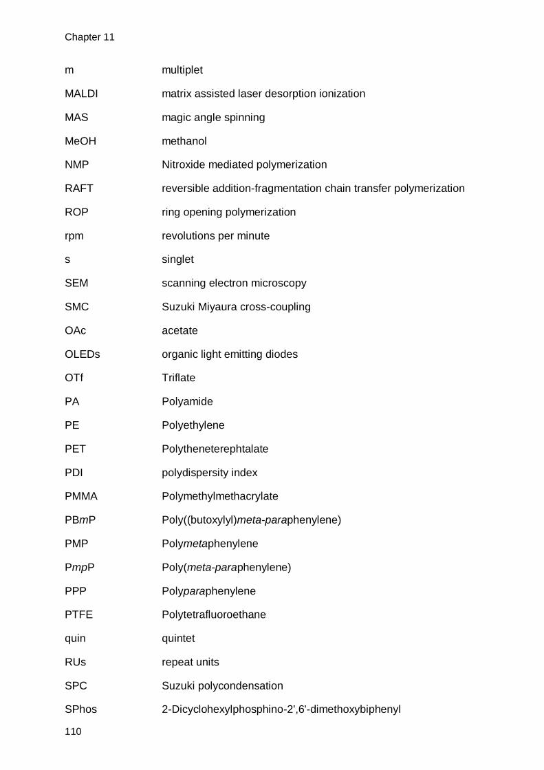
Chapter 11
110
m multiplet
MALDI matrix assisted laser desorption ionization
MAS magic angle spinning
MeOH methanol
NMP Nitroxide mediated polymerization
RAFT reversible addition-fragmentation chain transfer polymerization
ROP ring opening polymerization
rpm revolutions per minute
s singlet
SEM scanning electron microscopy
SMC Suzuki Miyaura cross-coupling
OAc acetate
OLEDs organic light emitting diodes
OTf Triflate
PA Polyamide
PE Polyethylene
PET Polytheneterephtalate
PDI polydispersity index
PMMA Polymethylmethacrylate
PBmP Poly((butoxylyl)meta-paraphenylene)
PMP Polymetaphenylene
PmpP Poly(meta-paraphenylene)
PPP Polyparaphenylene
PTFE Polytetrafluoroethane
quin quintet
RUs repeat units
SPC Suzuki polycondensation
SPhos 2-Dicyclohexylphosphino-2',6'-dimethoxybiphenyl

Appendix
111
t triplet
TGA thermo-gravimetric analysis
THF Tetrahydrofurane
TOF time of flight
Tol tolyl
TLC thin layer chromatography
UV/Vis Ultraviolet-visible
XRD X-ray diffraction

Chapter 12
112
12. References
[1] Plastics Europe, 2012. [2] H. Staudinger, Ber. Dtsch. Chem. Ges. 1920, 53, 1073-1085. [3] H. Staudinger, Ber. Dtsch. Chem. Ges. 1924, 57, 1203-1208. [4] R. Freudenberger, W. Claussen, A. D. Schlüter, H. Wallmeier, Polymer 1994,
35, 4496-4501. [5] I. K. Spiliopoulos, J. A. Mikroyannidis, Macromolecules 1996, 29, 5313-5319.
[6] R. Kandre, K. Feldman, H. E. H. Meijer, P. Smith, A. D. Schlüter, Angew. Chem. Int. Ed. 2007, 46, 4956-4959.
[7] A. R. Postema, K. Liou, F. Wudl, P. Smith, Macromolecules 1990, 23, 1842-1845.
[8] P.-O. Johansson, J. Lindberg, M. J. Blackman, I. Kvarnström, L. Vrang, E. Hamelink, A. Hallberg, Å. Rosenquist, B. Samuelsson, J. Med. Chem. 2005,
48, 4400-4409. [9] S. Caron, A. Ghosh, S. Gut Ruggeri, N. D. Ide, J. D. Nelson, J. A. Ragan, in
Practical Synthetic Organic Chemistry, John Wiley & Sons, Inc., 2011, pp. 279-340.
[10] N. Miyaura, K. Yamada, A. Suzuki, Tetrahedron Lett. 1979, 20, 3437-3440. [11] N. Miyaura, A. Suzuki, J. Chem. Soc., Chem. Commun. 1979, 866-867. [12] S. Baba, E. Negishi, J. Am. Chem. Soc. 1976, 98, 6729-6731. [13] R. C. Larock, The Journal of Organic Chemistry 1976, 41, 2241-2246. [14] D. Milstein, J. K. Stille, J. Am. Chem. Soc. 1978, 100, 3636-3638. [15] H. A. Dieck, R. F. Heck, J. Am. Chem. Soc. 1974, 96, 1133-1136. [16] J. K. Stille, Angewandte Chemie International Edition in English 1986, 25, 508-
524. [17] A. O. Aliprantis, J. W. Canary, J. Am. Chem. Soc. 1994, 116, 6985-6986. [18] N. Miyaura, K. Yamada, H. Suginome, A. Suzuki, J. Am. Chem. Soc. 1985,
107, 972-980. [19] H. Nakai, S. Ogo, Y. Watanabe, Organometallics 2002, 21, 1674-1678. [20] V. V. Grushin, H. Alper, Chem. Rev. 1994, 94, 1047-1062. [21] J.-P. Corbet, G. Mignani, Chem. Rev. 2006, 106, 2651-2710. [22] A. L. Casado, P. Espinet, Organometallics 1998, 17, 954-959. [23] N. Miyaura, A. Suzuki, Chem. Rev. 1995, 95, 2457-2483. [24] M. Rehahn, A.-D. Schlüter, G. Wegner, W. J. Feast, Polymer 1989, 30, 1060-
1062. [25] J. Sakamoto, M. Rehahn, G. Wegner, A. D. Schlüter, Macromol. Rapid
Commun. 2009, 30, 653-687. [26] G. Brodowski, A. Horvath, M. Ballauff, M. Rehahn, Macromolecules 1996, 29,
6962-6965. [27] B. Hohl, L. Bertschi, X. Zhang, A. D. Schlüter, J. Sakamoto, Macromolecules
2012, 45, 5418-5426. [28] W. H. Carothers, Transactions of the Faraday Society 1936, 32, 39-49. [29] Z. Bo, A. D. Schlüter, Chemistry – A European Journal 2000, 6, 3235-3241. [30] J. Murage, J. W. Eddy, J. R. Zimbalist, T. B. McIntyre, Z. R. Wagner, F. E.
Goodson, Macromolecules 2008, 41, 7330-7338. [31] W. Zhang, P. Lu, Z. Wang, Y. Ma, J. Polym. Sci., Part A: Polym. Chem. 2013,
51, 1950-1955. [32] Z. Xue, A. D. Finke, J. S. Moore, Macromolecules 2010, 43, 9277-9282.
References
113
[33] Z. Z. Song, H. N. C. Wong, The Journal of Organic Chemistry 1994, 59, 33-41. [34] C. M. So, Z. Zhou, C. P. Lau, F. Y. Kwong, Angew. Chem. Int. Ed. 2008, 47,
6402-6406. [35] D. Zim, S. L. Buchwald, Org. Lett. 2003, 5, 2413-2415. [36] S. D. Walker, T. E. Barder, J. R. Martinelli, S. L. Buchwald, Angew. Chem. Int.
Ed. 2004, 43, 1871-1876. [37] N. E. Leadbeater, M. Marco, The Journal of Organic Chemistry 2003, 68,
5660-5667. [38] H. Yan, P. Lee, N. R. Armstrong, A. Graham, G. A. Evmenenko, P. Dutta, T. J.
Marks, J. Am. Chem. Soc. 2005, 127, 3172-3183. [39] W. W. Inbasekaran; Michael, Woo; Edmund P., in U.S. Patent, 5.777.070,
1997. [40] B. Liu, W.-L. Yu, Y.-H. Lai, W. Huang, Macromolecules 2000, 33, 8945-8952.
[41] F. Galbrecht, T. W. Bünnagel, U. Scherf, T. Farrell, Macromol. Rapid Commun. 2007, 28, 387-394.
[42] S. Jakob, A. Moreno, X. hang, L. Bertschi, P. Smith, A. D. Schl ter, J. Sakamoto, Macromolecules 2010, 43, 7916-7918.
[43] K. T. Nielsen, K. Bechgaard, F. C. Krebs, Macromolecules 2005, 38, 658-659. [44] A. Schätz, O. Reiser, W. J. Stark, Chemistry – A European Journal 2010, 16,
8950-8967. [45] . M. Scheuermann, L. Rumi, P. Steurer, W. Bannwarth, R. M lhaupt, J. Am.
Chem. Soc. 2009, 131, 8262-8270. [46] K. C. Kong, C. H. Cheng, J. Am. Chem. Soc. 1991, 113, 6313-6315.
[47] W. A. Herrmann, C. Broßmer, T. Priermeier, K. Öfele, J. Organomet. Chem. 1994, 481, 97-108.
[48] D. Agrawal, E.-L. Zins, D. Schröder, Chemistry – An Asian Journal 2010, 5, 1667-1676.
[49] F. E. Goodson, T. I. Wallow, B. M. Novak, Macromolecules 1998, 31, 2047-2056.
[50] J. Frahn, B. Karakaya, A. Schäfer, A. D. Schlüter, Tetrahedron 1997, 53, 15459-15467.
[51] H. G. Kuivila, J. F. Reuwer Jr, J. A. Mangravite, Can. J. Chem. 1963, 41, 3081-3090.
[52] T. Bauer, A. D. Schlüter, J. Sakamoto, Synlett 2010, 2010, 877-880. [53] H. G. Kuivila, J. F. Reuwer, J. A. Mangravite, J. Am. Chem. Soc. 1964, 86,
2666-2670. [54] M.-S. Schiedel, C. A. Briehn, P. Bäuerle, J. Organomet. Chem. 2002, 653,
200-208. [55] A. J. J. Lennox, G. C. Lloyd-Jones, J. Am. Chem. Soc. 2012, 134, 7431-7441.
[56] M. Moreno-Mañas, M. Pérez, R. Pleixats, The Journal of Organic Chemistry 1996, 61, 2346-2351.
[57] H. Sibtain, A. B. Stephen, in Synthetics, Mineral Oils, and Bio-Based Lubricants, CRC Press, 2005.
[58] D. G. H. Ballard, A. Courtis, I. M. Shirley, S. C. Taylor, Macromolecules 1988,
21, 294-304. [59] P. Kovacic, C. Wu, Journal of Polymer Science 1960, 47, 45-54. [60] A. A. Berlin, Journal of Polymer Science 1961, 55, 621-641. [61] G. Goldschimiedt, Monatshefte für Chemie und verwandte Teile anderer
Wissenschaften 1886, 7, 40-47. [62] T. Yamamoto, Y. Hayashi, A. Yamamoto, Bull. Chem. Soc. Jpn. 1978, 51,
2091-2097.

Chapter 12
114
[63] J. L. Musfeldt, J. R. Reynolds, D. B. Tanner, J. P. Ruiz, J. Wang, M. Pomerantz, J. Polym. Sci., Part B: Polym. Phys. 1994, 32, 2395-2404.
[64] J. L. Reddinger, J. R. Reynolds, Macromolecules 1997, 30, 479-481. [65] V. S. Claesson, R. Gehm, W. Kern, Die Makromolekulare Chemie 1951, 7, 46-
61. [66] J. Majnusz, J. M. Catala, R. W. Lenz, Eur. Polym. J. 1983, 19, 1043-1046. [67] M. Ballauff, G. F. Schmidt, Molecular Crystals and Liquid Crystals 1987, 147,
163-177. [68] M. B. Jones, P. Kovacic, D. Lanska, Journal of Polymer Science: Polymer
Chemistry Edition 1981, 19, 89-101. [69] M. Rehahn, A.-D. Schlüter, G. Wegner, Die Makromolekulare Chemie 1990,
191, 1991-2003. [70] C. Ambrosch-Draxl, J. A. Majewski, P. Vogl, G. Leising, Physical Review B
1995, 51, 9668-9676. [71] M. P. Stevens, 3rd ed., Oxford University Press, 1999, p. 485. [72] J. H. Edwards, W. J. Feast, Polymer 1980, 21, 595-596. [73] D. A. Halliday, P. L. Burn, R. H. Friend, A. B. Holmes, J. Chem. Soc., Chem.
Commun. 1992, 0, 1685-1687. [74] J. M. Batson, T. M. Swager, ACS Macro Letters 2012, 1, 1121-1123. [75] D. R. McKean, J. K. Stille, Macromolecules 1987, 20, 1787-1792. [76] Z. He, F. J. Davis, G. R. Mitchell, Polymer 1994, 35, 2218-2221.
[77] E. Bundgaard, O. Hagemann, M. Bjerring, N. C. Nielsen, J. W. Andreasen, B. Andreasen, F. C. Krebs, Macromolecules 2012, 45, 3644-3646.
[78] J. Liu, E. N. Kadnikova, Y. Liu, M. D. McGehee, J. M. J. Fréchet, J. Am. Chem. Soc. 2004, 126, 9486-9487.
[79] R. Gedye, F. Smith, K. Westaway, H. Ali, L. Baldisera, L. Laberge, J. Rousell, Tetrahedron Lett. 1986, 27, 279-282.
[80] R. J. Giguere, T. L. Bray, S. M. Duncan, G. Majetich, Tetrahedron Lett. 1986, 27, 4945-4948.
[81] M. Larhed, A. Hallberg, The Journal of Organic Chemistry 1996, 61, 9582-9584.
[82] C. Ebner, T. Bodner, F. Stelzer, F. Wiesbrock, Macromol. Rapid Commun. 2011, 32, 254-288.
[83] K. Kempe, C. R. Becer, U. S. Schubert, Macromolecules 2011, 44, 5825-5842. [84] R. M. Paulus, C. R. Becer, R. Hoogenboom, U. S. Schubert, Aust. J. Chem.
2009, 62, 254-259. [85] D. Roy, A. Ullah, B. S. Sumerlin, Macromolecules 2009, 42, 7701-7708. [86] Y. Kwak, R. T. Mathers, K. Matyjaszewski, Macromol. Rapid Commun. 2012,
33, 80-86. [87] B. S. Nehls, U. Asawapirom, S. Füldner, E. Preis, T. Farrell, U. Scherf, Adv.
Funct. Mater. 2004, 14, 352-356. [88] B. S. Nehls, S. Füldner, E. Preis, T. Farrell, U. Scherf, Macromolecules 2005,
38, 687-694. [89] W. Zhang, P. Lu, Z. Wang, Y. Ma, Sci. China Chem. 2012, 55, 844-849. [90] A. Greiner, J. H. Wendorff, Angew. Chem. Int. Ed. 2007, 46, 5670-5703. [91] G. Srinivasan, D. H. Reneker, Polym. Int. 1995, 36, 195-201. [92] R. Kessick, J. Fenn, G. Tepper, Polymer 2004, 45, 2981-2984. [93] H. Fong, I. Chun, D. H. Reneker, Polymer 1999, 40, 4585-4592. [94] S. Agarwal, A. Greiner, J. H. Wendorff, Prog. Polym. Sci. 2013, 38, 963-991. [95] S. Ramakrishna, K. Fujihara, W.-E. Teo, T.-C. Lim, Z. Ma, An Introduction To
Electrospinning And Nanofibers, World Scientific Publishing, 2005.

References
115
[96] J. Xia, S. Yuan, Z. Wang, S. Kirklin, B. Dorney, D.-J. Liu, L. Yu, Macromolecules 2010, 43, 3325-3330.
[97] P. Li, J. Li, F. Arikan, W. Ahlbrecht, M. Dieckmann, D. Menche, The Journal of Organic Chemistry 2010, 75, 2429-2444.
[98] P. Kissel, S. Breitler, V. Reinmüller, P. Lanz, L. Federer, A. D. Schlüter, J. Sakamoto, Eur. J. Org. Chem. 2009, 2009, 2953-2955.
[99] L. I. Zakharkin, I. M. Khorlina, Tetrahedron Lett. 1962, 3, 619-620.
[100] M. Alami, C. Amatore, S. Bensalem, A. Choukchou-Brahim, A. Jutand, Eur. J. Inorg. Chem. 2001, 2001, 2675-2681.
[101] T. S. Khaibulova, I. A. Boyarskaya, V. P. Boyarskii, Russ. J. Org. Chem. 2013, 49, 360-365.
[102] G. Lu, H. Usta, C. Risko, L. Wang, A. Facchetti, M. A. Ratner, T. J. Marks, J. Am. Chem. Soc. 2008, 130, 7670-7685.
[103] F. Dierschke, A. C. Grimsdale, K. Müllen, Synthesis 2003, 2003, 2470-2472. [104] Y. Chen, F. Li, Z. Bo, Macromolecules 2010, 43, 1349-1355.
[105] C.-C. Chi, C.-L. Chiang, S.-W. Liu, H. Yueh, C.-T. Chen, C.-T. Chen, J. Mater. Chem. 2009, 19, 5561-5571.
[106] F. Francuskiewicz, Polymer Fractionation, Springer Berlin Heidelberg, 1994. [107] M. Sun, Y. Fu, J. Li, Z. Bo, Macromol. Rapid Commun. 2005, 26, 1064-1069.
[108] J. Clayden, S. Warren, N. Greeves, P. Wothers, Organic Chemistry, Vol. 5, Oxford University Press, 2001.
[109] E. Pretsch, P. Bühlmann, C. Affolter, M. Badertscher, Spektroskopische Daten zur Strukturaufklärung organischer Verbindungen, Vol. 4, Springer Verlag, 2001.
[110] D. A. M. gbe, S. T rk, S. Rathgeber, . K hnlenz, R. Jadhav, A. Wild, . Birckner, . Adam, A. Pivrikas, V. Cimrova, . n. Kn r, . S. Sariciftci, H. Hoppe, Macromolecules 2010, 43, 1261-1269.
[111] H. Jun Song, D. Hun Kim, M. Hee Choi, S. Won Heo, J. Young Lee, J. Yong Lee, D. Kyung Moon, Sol. Energy Mater. Sol. Cells 2013, 117, 285-292.
[112] K. N. Baker, A. V. Fratini, T. Resch, H. C. Knachel, W. W. Adams, E. P. Socci, B. L. Farmer, Polymer 1993, 34, 1571-1587.
[113] F. C. Krebs, H. Spanggaard, Chem. Mater. 2005, 17, 5235-5237. [114] H. Fong, D. H. Reneker, J. Polym. Sci., Part B: Polym. Phys. 1999, 37, 3488-
3493. [115] D. Kołbuk, P. Sajkiewicz, T. A. Kowalewski, Eur. Polym. J. 2012, 48, 275-283. [116] J. M. Deitzel, J. D. Kleinmeyer, J. K. Hirvonen, N. C. Beck Tan, Polymer 2001,
42, 8163-8170. [117] L. Larrondo, R. St. John Manley, Journal of Polymer Science: Polymer Physics
Edition 1981, 19, 909-920. [118] X. Zong, K. Kim, D. Fang, S. Ran, B. S. Hsiao, B. Chu, Polymer 2002, 43,
4403-4412. [119] U. W. Gedde, Polymer Physics, Vol. 1, Kluwer Academic Publishers, 1995. [120] C. A. Tolman, W. C. Seidel, D. H. Gerlach, J. Am. Chem. Soc. 1972, 94, 2669-
2676. [121] S. Trimpin, A. Rouhanipour, R. Az, H. J. Räder, K. Müllen, Rapid Commun.
Mass Spectrom. 2001, 15, 1364-1373.
[122] A. P. Hammersley, S. O. Svensson, M. Hanfland, A. N. Fitch, D. Hausermann, High Pressure Research 1996, 14, 235-248.
[123] U. Lauter, W. H. Meyer, G. Wegner, Macromolecules 1997, 30, 2092-2101. [124] A. Balamurugan, M. L. P. Reddy, M. Jayakannan, The Journal of Physical
Chemistry B 2011, 115, 10789-10800.

Chapter 12
116
[125] A. V. Malkov, K. Vranková, R. C. Sigerson, S. Stončius, P. Kočovský, Tetrahedron 2009, 65, 9481-9486.
[126] S. H. Chanteau, J. M. Tour, The Journal of Organic Chemistry 2003, 68, 8750-
8766. [127] J. I. G. Cadogan, M. Cameron-Wood, R. K. Mackie, R. J. G. Searle, Journal of
the Chemical Society (Resumed) 1965, 4831-4837.

Acknowledgements
117
Acknowledgments
While my name is written on the cover of this booklet, I couldn’t have done so
without the major or minor help of the following people.
First and foremost I would like to thank Prof. A. Dieter Schlüter for his help and
guidance throughout my PhD. Feeling his support especially during difficult times was
vital during my doctoral studies.
I would also like to thank Prof. Junji Sakamoto for supervising me during the
first part of my PhD and providing important ideas to the project.
I am thankfull to Prof. Paul Smith and Prof. Holger Frauenrath for taking the
time need for co-refereeing my thesis.
I would, especially, like to thank Dr. Thomas Schweizer for his instructions and
insight into GPC, DSC, TGA, Rheology and other daily problems in the lab.
Many thanks to Prof. Theo Tervoort and Dr. Kirill Feldman for their help and
discussions, regarding polymer processing and ligh-microscopy.
Thanks to Dr. René Verel for help with NMR spectroscopy, particularly setting
up the machine for a multitude of solid-state NMR measurements.
Thanks to the ETH Zurich mass service headed by Dr. Xiangyang Zhang for
mass spectroscopy analysis. Most noteworthy Dr. Louis Bertschi for measuring many
MALDI-TOF mass-spectra for me.
The help of Dr. Julia Dschemuchadse with measuring XRD, Olivera Evrova with
electrospinning and Jingyi Rao with SEM measurements is gratefully acknowledged.
I would like to thank my students Gian Cadisch and Andreas Bielmann for their
help in the lab and John E. Philips for proofreading.
I would like to thank all the former and current member of the Schlüter-group for
the nice working atmosphere. Most notably: Dr. Benjamin Hohl for constant exchange
of ideas, doubts and hopes surrounding Suzuki-Polycondensation, my lab mates
Jingyi, Simon, Andri and Wenjang for the extraordinary working atmosphere, the
“dr ” people for good laughs and fruitful discussion over a cup of coffee.

Acknowledgements
118
I would like to thank my friends for helping me refresh my mind, gain new
energy, funny and sad moments which they shared with me during my time at ETH:
Anna, Esther, Marco, Raphael, Matthias, Nicola, Christian, Philip, Beat, Martin, Dave
H., Sara, Vincent, Thomas, Christian O., Lars M., Lars N., Hannes, Peter, Dave M.,
Christina and Sandra. Without you live would just be so much less fun.
At last but not least I would like to thank my family. Most of all my parents
Christina and Andreas, but also my siblings Ruth, Lee, Benjamin and Annina. Thank
you for just loving me the way I am, you are awesome!

Curriculum Vitae
119
Curriculum Vitae
Personal
Name: Samuel Paul Jakob
Citizen of Hombrechtikon (ZH)
Date of birth: 09.09.1983
Education
1996-2002 Mature (Old languages), Kantonsschule zürcher Oberland
Wetzikon, Switzerland
2003-2008 Bachelor of Science in Chemistry, ETH Zurich, Switzerland
2008-2010 Master of Science in Chemistry, ETH Zurich, Switzerland
2010-2014 Doctor of Sciences, ETH Zurich, Switzerland
Work experiences
07.2005 – 09.2005 Tecan Group Ltd. (Männedorf, Switzerland), Liquid Handling
Engenieer, Development of a laboratory robot for clinical
diagnostics
02.2010 - 01.2014 ETH Zurich (Zurich, Switzerland), PhD Program
Synthesis of Polyphenylenes with removable side chains -
towards an all Polyphenylene material
Miscellaneous
09.2002-11.2002 Wimbledon School of English (Wimbledon, England),
Language Studies

List of Publications
120
List of publications
Papers
N- Arylated 3,5-dihydro-4H-dinaphtho[2,1-c:1',2'-e]azepines: Axially chiral donors with high
helical twisting powers for nonplanar push-pull chromophores, Frank, Brian B.; Camafort Blanco,
Berta; Jakob, Samuel; Ferroni, Fiammetta; Pieraccini, Silvia; Ferrarini, Alberta; Boudon, Corinne;
Gisselbrecht, Jean-Paul; Seiler, Paul; Spada, Gian Piero; Diederich, Francois, Chemistry - A
European Journal, 2009, 15, 9005-9016.
Synthesis of Polyphenylenes from a Soluble Precursor: The "Shaving" Approach, Jakob,
Samuel; Moreno, Aitor; Zhang, Xyanjang; Bertschi, Louis; Smith, Paul; Schlüter, A. Dieter; Sakamoto,
Junji, Macromolecules, 2010, 43, 7916-7918.
Synthesis of poly(m,p-phenylene)s by Suzuki polycondensation using AA/BB monomers, Jakob,
Samuel; Schlüter, A. Dieter; Sakamoto, Junji, Polymer Preprints (American Chemical Society, Division
of Polymer Chemistry), 2011, 52, 368-369.
Posters
“Shaving” of polymer: A route to bare polyphenylenes, Jakob, Samuel; Moreno, Aitor; Zhang,
Xyanjang; Bertschi, Louis; Smith, Paul; Schlüter, A. Dieter; Sakamoto, Junji, 2010, EuChems
Nürnberg.
Synthesis of Poly(m-phenylene)s and Poly(m,p-phenylene)s by Suzuki polycondensation, Hohl,
Benjamin; Jakob, Samuel; Sakamoto, Junji; Schlüter, A. Dieter, 2010, SCS Fall meeting Zürich.
Synthesis of poly(m,p-phenylene)s by Suzuki polycondensation using AA/BB monomers, Jakob,
Samuel; Schlüter, A. Dieter; Sakamoto, Junji, 2011, ACS Fall meeting Denver.
Towards new polymeric materials based on poly(m,p-phenylene) by Suzuki polycondensation,
Jakob, Samuel; Schlüter, A. Dieter; Sakamoto, Junji, 2012, SCS Fall meeting Zürich.