rion – antirion bridge project – concrete durability towards corrosion … · ·...
TRANSCRIPT
Cussigh, Carde, Papanikolas, Stathopoulos-Vlamis 3rd fib International Congress – 2010
RION – ANTIRION BRIDGE PROJECT – CONCRETE DURABILITY TOWARDS
CORROSION RISK
François Cussigh, Concrete Expert, Vinci Construction France, France Christophe Carde, Technical Director, LERM laboratory, France
Panayotis Papanikolas, PhD, Vice-Chairman and Managing Director, GEFYRA S.A. – Concession Company for the Rion-Antirion Bridge, Greece
Aris Stathopoulos - Vlamis, Structural Maintenance Manager, GEFYRA S.A. – Concession Company for the Rion-Antirion Bridge, Greece
ABSTRACT
The concrete durability was a major issue for Rion-Antirion Bridge project in Greece due to the adverse environmental site conditions and the contractual requirement of 120 years service life. The strategy adopted is the corrosion control of embedded steel by reducing the rate of chloride penetration, which is the great challenge for the durability, and long service life achievement of concrete structures in marine environment. This objective was based on the proper definition of exposure zones, the definition of the appropriate concrete covers and a proper characterization and evaluation of concrete itself. Specific tests related to the concrete durability parameters were performed systematically at site laboratory for all mixes used in the project. Acceptance criteria had been set based on experience. Furthermore, an analysis of concrete durability including a service life assessment had been carried out by LERM laboratory. Finally, strict QA/QC procedures were closely followed during construction to achieve conformity of in-situ quality with that of laboratory. An additional test schedule is specified in the Inspection and Maintenance Manual during operation in order to evaluate the concrete durability. The results obtained during the first two years after the end of construction confirm the initial assessments ensuring the overall service life of 120 years.
Keywords: Marine Environment, High Performance Concrete, QA/QC Program, Service Life Assessment
Cussigh, Carde, Papanikolas, Stathopoulos-Vlamis 3rd fib International Congress – 2010
1
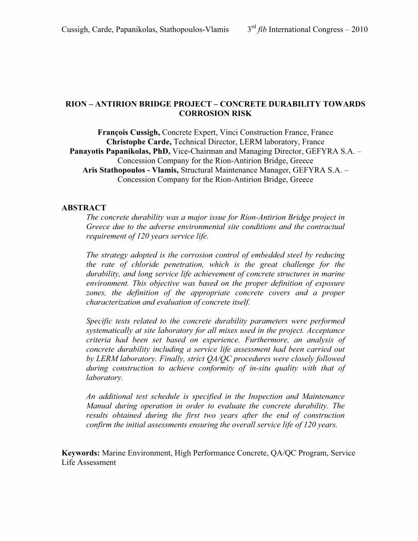
INTRODUCTION The Rion-Antirion Bridge, which was given to traffic in August 2004, consists of the longest multi-span cable stayed bridge in the world with a continuous deck of 2,252 meters and more than 600 meters of approach viaducts and further access roads. It is located in the Gulf of Corinth of Greece and as part of European road network links the Peloponnesus to Continental Greece. The main bridge is a 5-span cable stayed bridge with three spans of 560m and two side ones of 286m. The highest pier/pylon has a total height of 228.5m with the deepest point being 63.5m underwater. The main pier foundations measure 90 meters in diameter. The pier bases were constructed on-site, before they were floated into position in the Gulf, and lowered onto the seabed using water as ballast. The four main pylons were built in concrete using climbing shutters, and they reach 164 meters above sea level.
Fig. 1 Rion-Antirion Bridge Project
A major issue was the long-term performance of concrete structures in a marine environment since the contractual specifications were requiring a service life of 120 years. A specific strategy for the long-term concrete durability was adopted and various tests were performed to validate the specifications. Additionally, a QA/QC program was strictly followed for concrete production/construction to achieve a homogeneous structure fulfilling the specifications. Further to that, the Supervisor Engineer instructed several tests at specific locations. For the follow up of concrete durability a program has been set, which defines specific tests to be performed during the operational period on regular basis in order to measure the chlorides penetration, to determine the chlorides diffusivity and assess the overall service life of the structure.
Cussigh, Carde, Papanikolas, Stathopoulos-Vlamis 3rd fib International Congress – 2010
2
CONCRETE DURABILITY STRATEGY In order to achieve the 120 years of service life, it was very important to characterize and evaluate properly the concrete's ability to protect the embedded steel from corrosion. The three major degradation risks on reinforced concrete were the chemical attack by seawater, the corrosion induced by chlorides, the corrosion induced by CO2. The strategy chosen to protect the steel relied mainly on concrete durability, which includes a proper definition of exposure zones, the definition of appropriate concrete covers, and a proper characterization and evaluation of concrete itself. EXPOSURE ZONES The structure was divided into the following parts: • Pile Viaducts Foundations (bored or composite) • Substructure externally exposed below MSL (Mean Sea Level) +10m divided into:
o Immersed zone below MSL –5m o Tidal & splash zone between MSL –5m & MSL +10m
• Substructure externally exposed above MSL +10m • Substructure overland • Bridge and Viaducts Superstructure The most exposed zones in terms of corrosion risk are the structures externally exposed below MSL + 10m. The immersed zone (below MSL -5.0m) is much less critical than the splash and tidal zone (between MSL -5.0m and MSL +10.0m), due to the lack of oxygen in this area. DEFINITION OF COVERS The different covers of the structure have been defined, with the assistance of concrete durability experts, in accordance to the durability criteria selected. As a result, higher cover than contractually required has been selected (for the same exposure zone), especially in critical zones. Table 1 summarizes the covers selected for the Rion-Antirion Bridge and applied throughout construction for the different exposure zones. A comparison with the contractual specifications shows that in the ‘immersed zone’ and ‘tidal and splash zone’ the cover has been increased by 20% and 13%, respectively. Table 1 Covers in relation to exposure zone (values are in mm)
Exposure Situation Contractual
Specifications (mm) Minimum
Nominal Cover (mm)
Viaducts Pile Foundations (bored or composite) - 100 Immersed zone (below MSL –5m) 50 60 Tidal & Splash (MSL –5m to MSL +10m) 75 85 Substructure externally exposed above MSL +10m 50 50 Substructure over land 45 50
Cussigh, Carde, Papanikolas, Stathopoulos-Vlamis 3rd fib International Congress – 2010
3
Deck lower free surface 40 40 Bridge & Viaduct Superstructure Deck upper surface 30 30
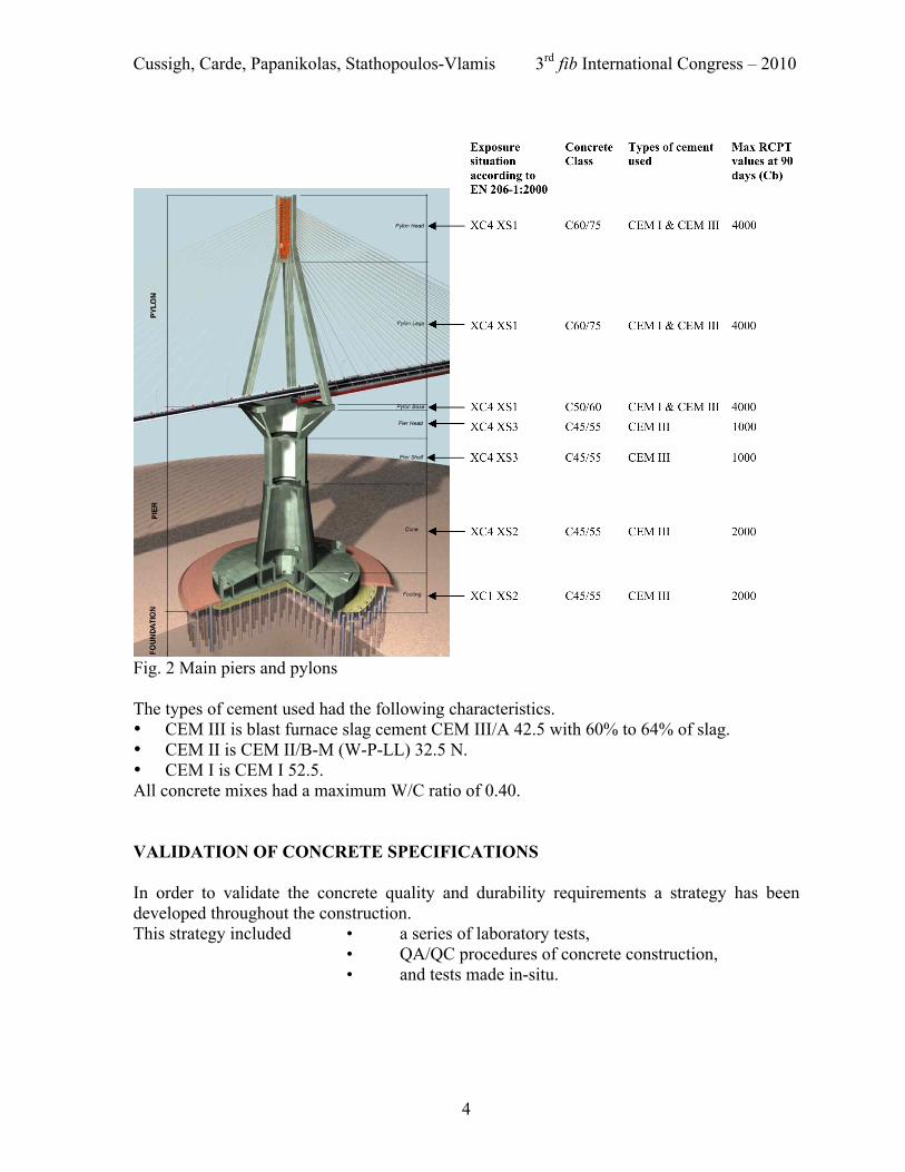
CONCRETE SPECIFICATIONS TOWARDS DURABILITY Concrete specifications refer mainly to the selection of the constituents, the content of cement and the Water/Cement Ratio, according to the exposure situation of each part of the structure, with special specifications for marine environment. Selection of constituents The concrete constituents have been selected by mix design experts in order to ensure the required quality of the concrete in situ. The stability of concrete constituents, their properties and their proportions were major factors to guarantee a constant and uniform concrete production. They were established after a long series of trials. Cement Most of concrete mixes have been mixed with cement type CEM III 42.5 PM ES with slag content higher than 60%. A local supplier had specially produced this type of cement according to the project's requirements. It had a low heat of hydration and was adequate for marine exposure environments. The other types used are shown below in figure 2. Aggregates The aggregates used were crushed limestone stone and came from the quarry of a local supplier. It was divided in three fractions: coarse1 10/20, coarse2 4/10 and sand 0/4. The aggregate supplier had to supply specific sand, in which the fines content was regulated around 9%. Siliceous sand could not been used because of alkali-silica reaction risks. Admixtures The admixtures had been chosen among numerous products. For instance, Optima 100, Glenium 27 and Rheobuilt T3 had been selected for their technical characteristics. Figure 2 presents the concrete class with the cement type for the main piers and pylons structures.
Cussigh, Carde, Papanikolas, Stathopoulos-Vlamis 3rd fib International Congress – 2010
4
Fig. 2 Main piers and pylons The types of cement used had the following characteristics. • CEM III is blast furnace slag cement CEM III/A 42.5 with 60% to 64% of slag. • CEM II is CEM II/B-M (W-P-LL) 32.5 N. • CEM I is CEM I 52.5. All concrete mixes had a maximum W/C ratio of 0.40. VALIDATION OF CONCRETE SPECIFICATIONS In order to validate the concrete quality and durability requirements a strategy has been developed throughout the construction. This strategy included • a series of laboratory tests,
• QA/QC procedures of concrete construction, • and tests made in-situ.
Cussigh, Carde, Papanikolas, Stathopoulos-Vlamis 3rd fib International Congress – 2010
5
LABORATORY TESTS All the cores and samples tested were coming from concrete cast, which was made for laboratory purposes at the Site Batching Plant under the same conditions as those of regular production. Certain acceptance criteria, which were based on experience, had been chosen for the verification of the test results. Rapid Chloride Penetration Test and Water Penetration Test The RCPT1 result (Rapid Chloride Penetration Test), combined with the WDP2 (Water Penetration Test), were used as the main durability indicator. These two tests have been performed systematically at the KG site laboratory on all Conformity Trials for each different mix defined for the structure. The respect of fresh concrete parameters within acceptable tolerances defined in Trial Mix Reports, guaranteed results on hardened concrete (strength and durability characteristics) equivalent to the ones obtained during those conformity trials. The acceptance criteria for those tests have been chosen so that: • WDP ≤ 20mm • RCPT at 90 days ≤ 1000C (Coulomb) in the splash zone ≤ 2000C for substructures ≤ 4000C for piles-foundations and Bridge & Viaduct superstructure Table 2 RCPT results of concrete mixes used on site
Mix No
Class of Concrete Use of Mix Exposure Class Type and quantity of
Cement Dmax (mm)
W/C Ratio
RCPT Results min-max (C)
420 C45/55 Pier Base Substructure below MSL +10 CEM III 400 kg/m3 20 0.40 480-1050
425 428 C45/55 Cone
Octagon Immersed zone below MSL -5 CEM III 420 kg/m3 20 0.39 220-600
432 C45/55 Raft &
Walls in footing
Immersed zone below MSL –5 CEM III 450 kg/m3 10 0.40 430-880
520 C50/60 Pylon Base Substructure above MSL +10 CEM III 420 kg/m3 20 0.37 200-360
610 C60/75 Pier shaft slab
Splash zone MSL –5/+10 CEM III 490 kg/m3 20 0.33 220-390
620 C60/75 Pylon legs Superstructure of Main Bridge
CEM III 327 kg/m3 CEM I 163 kg/m3 20 0.33 270-575
612 C60/75 Deck on shore
Superstructure of Main Bridge CEM III 490 kg/m3 20 0.33 320-370
670 C60/75 Deck off shore
Superstructure of Main Bridge CEM I 450 kg/m3 20 0.33 1300-2100
Cussigh, Carde, Papanikolas, Stathopoulos-Vlamis 3rd fib International Congress – 2010
6
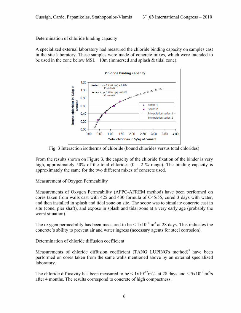
Determination of chloride binding capacity A specialized external laboratory had measured the chloride binding capacity on samples cast in the site laboratory. These samples were made of concrete mixes, which were intended to be used in the zone below MSL +10m (immersed and splash & tidal zone).
Fig. 3 Interaction isotherms of chloride (bound chlorides versus total chlorides)
From the results shown on Figure 3, the capacity of the chloride fixation of the binder is very high, approximately 50% of the total chlorides (0 – 2 % range). The binding capacity is approximately the same for the two different mixes of concrete used. Measurement of Oxygen Permeability Measurements of Oxygen Permeability (AFPC-AFREM method) have been performed on cores taken from walls cast with 425 and 430 formula of C45/55, cured 3 days with water, and then installed in splash and tidal zone on site. The scope was to simulate concrete cast in situ (cone, pier shaft), and expose in splash and tidal zone at a very early age (probably the worst situation). The oxygen permeability has been measured to be < 1x10-17m2 at 28 days. This indicates the concrete’s ability to prevent air and water ingress (necessary agents for steel corrosion). Determination of chloride diffusion coefficient Measurements of chloride diffusion coefficient (TANG LUPING's method)3 have been performed on cores taken from the same walls mentioned above by an external specialized laboratory. The chloride diffusivity has been measured to be < 1x10-12m2/s at 28 days and < 5x10-13m2/s after 4 months. The results correspond to concrete of high compactness.
Cussigh, Carde, Papanikolas, Stathopoulos-Vlamis 3rd fib International Congress – 2010
7
The results of chloride diffusion coefficient obtained at different ages on concrete blocks, combined with the chloride binding capacity of the cement paste have been used as input data in a finite element model used to simulate the service life of the bridge. The variation of the diffusion coefficient with respect to time is the most important parameter for the simulation. The equation used to describe its evolution corresponds to the general equations found in the literature 4 and used for the durability prediction of the Vasco Da Gama Bridge:
D = a t-α (1) where D: Chlorides diffusion coefficient in m2/s.
t: time in month. a and α : correspond respectively to the reference value of the chlorides diffusion
coefficient at t0, and to the aging factor. These terms are experimentally determined with the measurements of the chlorides diffusion coefficient at several age of the concrete.
The values initially taken were a=1x10-12 and α=0.4297, based on experimental data from Vasco Da Gama Bridge. The software used was already applied for the concrete durability of Vasco da Gama Bridge, which is located in the Tagus bay in Lisbon [Houdusse, Hornain and Martinet, 2000] 5. This software includes a mathematical model, which describes the transport equation of a chemical species, and a finite element model, which corresponds to the spatial discretization of the mathematical model. The numerical simulations permit a variation of concrete characteristics with space and time. Furthermore, the variation of the diffusion coefficient with respect to time is the one of the most important parameter for the simulation. Capillary and porosity tests – Resistivity In order to validate the high performance of the concrete especially used in immersed and splash zones after the recommendation of the concrete expert, Odd E. Gjørv6 (Norwegian University of Science and Technology) some further tests have been performed. The tests performed at KG site laboratory are the following: • Capillary and porosity tests • Resistivity measurements (use of RCPT test) The main results are presented in the following table.
Cussigh, Carde, Papanikolas, Stathopoulos-Vlamis 3rd fib International Congress – 2010
8
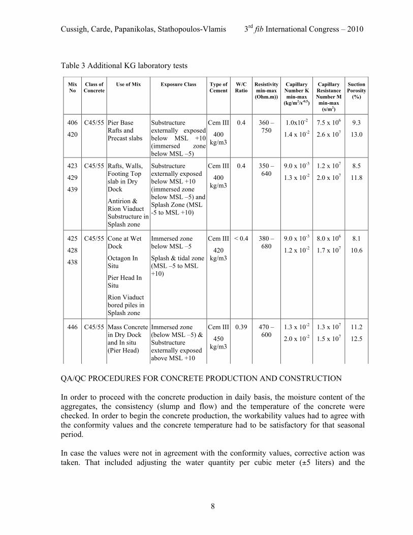
Table 3 Additional KG laboratory tests
QA/QC PROCEDURES FOR CONCRETE PRODUCTION AND CONSTRUCTION In order to proceed with the concrete production in daily basis, the moisture content of the aggregates, the consistency (slump and flow) and the temperature of the concrete were checked. In order to begin the concrete production, the workability values had to agree with the conformity values and the concrete temperature had to be satisfactory for that seasonal period. In case the values were not in agreement with the conformity values, corrective action was taken. That included adjusting the water quantity per cubic meter (±5 liters) and the
Mix No
Class of Concrete
Use of Mix Exposure Class Type of Cement
W/C Ratio
Resistivity min-max (Ohm.m))
Capillary Number K min-max
(kg/m2/s-0,5)
Capillary Resistance Number M min-max
(s/m2)
Suction Porosity
(%)
406
420
C45/55 Pier Base Rafts and Precast slabs
Substructure externally exposed below MSL +10 (immersed zone below MSL –5)
Cem III
400 kg/m3
0.4 360 – 750
1.0x10⁻²
1.4 x 10⁻²
7.5 x 10⁶
2.6 x 10⁷
9.3
13.0
423
429
439
C45/55 Rafts, Walls, Footing Top slab in Dry Dock
Antirion & Rion Viaduct Substructure in Splash zone
Substructure externally exposed below MSL +10 (immersed zone below MSL –5) and Splash Zone (MSL -5 to MSL +10)
Cem III
400 kg/m3
0.4 350 – 640
9.0 x 10⁻³
1.3 x 10⁻²
1.2 x 10⁷
2.0 x 10⁷
8.5
11.8
425
428
438
C45/55 Cone at Wet Dock
Octagon In Situ
Pier Head In Situ
Rion Viaduct bored piles in Splash zone
Immersed zone below MSL –5
Splash & tidal zone (MSL –5 to MSL +10)
Cem III
420 kg/m3
< 0.4 380 – 680
9.0 x 10⁻³
1.2 x 10⁻²
8.0 x 10⁶
1.7 x 10⁷
8.1
10.6
446 C45/55 Mass Concrete in Dry Dock and In situ (Pier Head)
Immersed zone (below MSL –5) & Substructure externally exposed above MSL +10
Cem III
450 kg/m3
0.39 470 – 600
1.3 x 10⁻²
2.0 x 10⁻²
1.3 x 10⁷
1.5 x 10⁷
11.2
12.5
Cussigh, Carde, Papanikolas, Stathopoulos-Vlamis 3rd fib International Congress – 2010
9
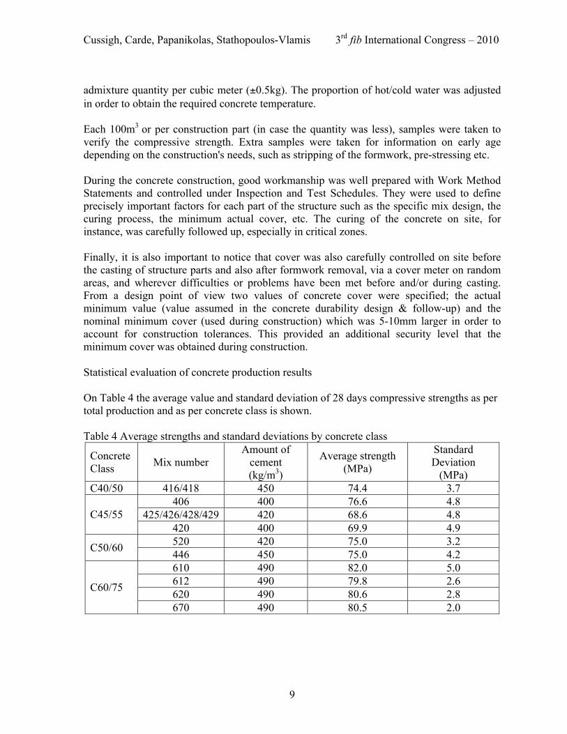
admixture quantity per cubic meter (±0.5kg). The proportion of hot/cold water was adjusted in order to obtain the required concrete temperature. Each 100m3 or per construction part (in case the quantity was less), samples were taken to verify the compressive strength. Extra samples were taken for information on early age depending on the construction's needs, such as stripping of the formwork, pre-stressing etc. During the concrete construction, good workmanship was well prepared with Work Method Statements and controlled under Inspection and Test Schedules. They were used to define precisely important factors for each part of the structure such as the specific mix design, the curing process, the minimum actual cover, etc. The curing of the concrete on site, for instance, was carefully followed up, especially in critical zones. Finally, it is also important to notice that cover was also carefully controlled on site before the casting of structure parts and also after formwork removal, via a cover meter on random areas, and wherever difficulties or problems have been met before and/or during casting. From a design point of view two values of concrete cover were specified; the actual minimum value (value assumed in the concrete durability design & follow-up) and the nominal minimum cover (used during construction) which was 5-10mm larger in order to account for construction tolerances. This provided an additional security level that the minimum cover was obtained during construction. Statistical evaluation of concrete production results On Table 4 the average value and standard deviation of 28 days compressive strengths as per total production and as per concrete class is shown. Table 4 Average strengths and standard deviations by concrete class
Concrete Class Mix number
Amount of cement (kg/m3)
Average strength (MPa)
Standard Deviation
(MPa) C40/50 416/418 450 74.4 3.7
406 400 76.6 4.8 425/426/428/429 420 68.6 4.8 C45/55
420 400 69.9 4.9 520 420 75.0 3.2 C50/60 446 450 75.0 4.2 610 490 82.0 5.0 612 490 79.8 2.6 620 490 80.6 2.8 C60/75
670 490 80.5 2.0
Cussigh, Carde, Papanikolas, Stathopoulos-Vlamis 3rd fib International Congress – 2010
10
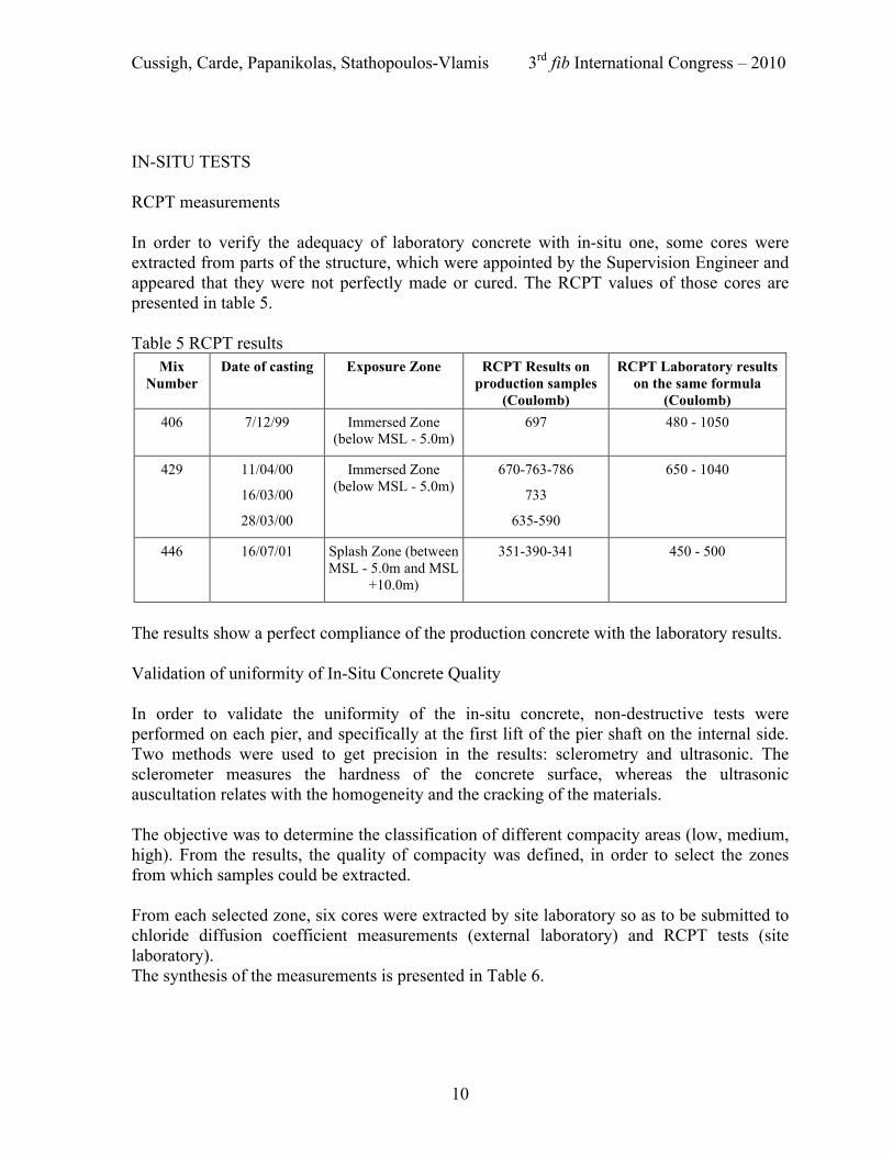
IN-SITU TESTS RCPT measurements In order to verify the adequacy of laboratory concrete with in-situ one, some cores were extracted from parts of the structure, which were appointed by the Supervision Engineer and appeared that they were not perfectly made or cured. The RCPT values of those cores are presented in table 5. Table 5 RCPT results
Mix Number
Date of casting Exposure Zone RCPT Results on production samples
(Coulomb)
RCPT Laboratory results on the same formula
(Coulomb) 406 7/12/99 Immersed Zone
(below MSL - 5.0m) 697 480 - 1050
429 11/04/00
16/03/00
28/03/00
Immersed Zone (below MSL - 5.0m)
670-763-786
733
635-590
650 - 1040
446 16/07/01 Splash Zone (between MSL - 5.0m and MSL
+10.0m)
351-390-341 450 - 500
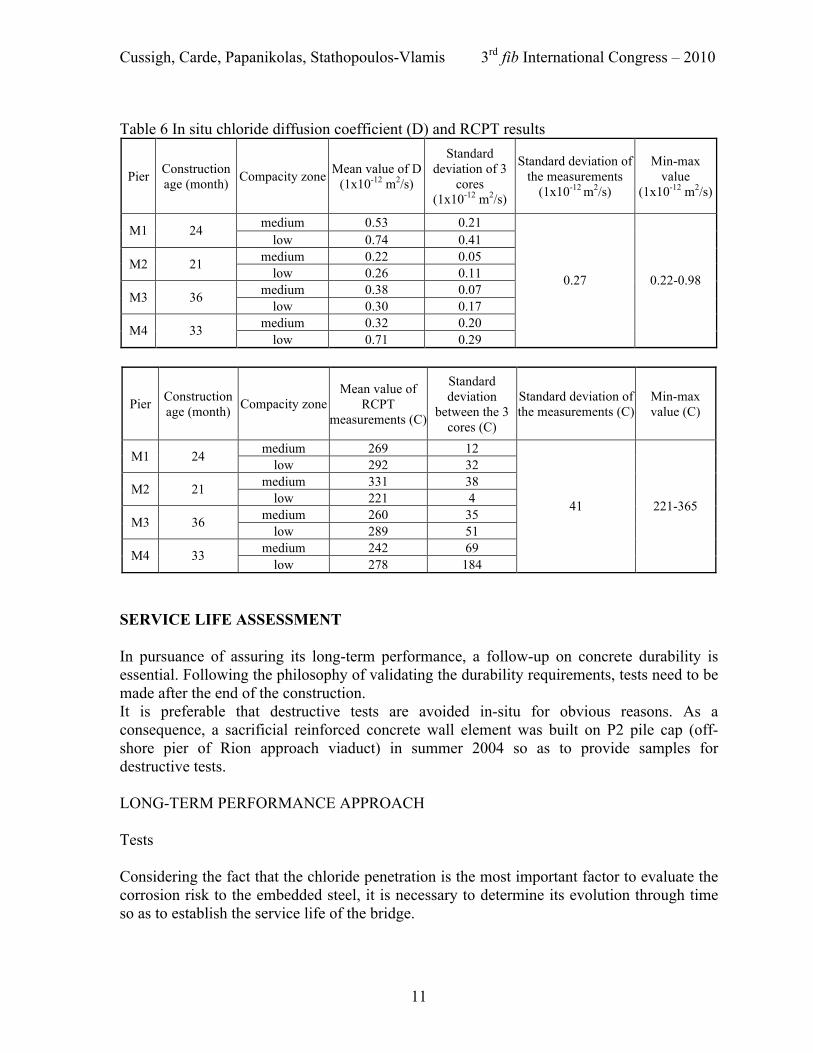
The results show a perfect compliance of the production concrete with the laboratory results. Validation of uniformity of In-Situ Concrete Quality In order to validate the uniformity of the in-situ concrete, non-destructive tests were performed on each pier, and specifically at the first lift of the pier shaft on the internal side. Two methods were used to get precision in the results: sclerometry and ultrasonic. The sclerometer measures the hardness of the concrete surface, whereas the ultrasonic auscultation relates with the homogeneity and the cracking of the materials. The objective was to determine the classification of different compacity areas (low, medium, high). From the results, the quality of compacity was defined, in order to select the zones from which samples could be extracted. From each selected zone, six cores were extracted by site laboratory so as to be submitted to chloride diffusion coefficient measurements (external laboratory) and RCPT tests (site laboratory). The synthesis of the measurements is presented in Table 6.
Cussigh, Carde, Papanikolas, Stathopoulos-Vlamis 3rd fib International Congress – 2010
11
Table 6 In situ chloride diffusion coefficient (D) and RCPT results
Pier Construction age (month) Compacity zone Mean value of D
(1x10-12 m2/s)
Standard deviation of 3
cores (1x10-12 m2/s)
Standard deviation of the measurements
(1x10-12 m2/s)
Min-max value
(1x10-12 m2/s)
medium 0.53 0.21 M1 24 low 0.74 0.41
medium 0.22 0.05 M2 21 low 0.26 0.11
medium 0.38 0.07 M3 36 low 0.30 0.17
medium 0.32 0.20 M4 33 low 0.71 0.29
0.27 0.22-0.98
Pier Construction age (month) Compacity zone
Mean value of RCPT
measurements (C)
Standard deviation
between the 3 cores (C)
Standard deviation of the measurements (C)
Min-max value (C)
medium 269 12 M1 24 low 292 32 medium 331 38 M2 21
low 221 4 medium 260 35 M3 36
low 289 51 medium 242 69 M4 33
low 278 184
41 221-365
SERVICE LIFE ASSESSMENT In pursuance of assuring its long-term performance, a follow-up on concrete durability is essential. Following the philosophy of validating the durability requirements, tests need to be made after the end of the construction. It is preferable that destructive tests are avoided in-situ for obvious reasons. As a consequence, a sacrificial reinforced concrete wall element was built on P2 pile cap (off-shore pier of Rion approach viaduct) in summer 2004 so as to provide samples for destructive tests. LONG-TERM PERFORMANCE APPROACH Tests Considering the fact that the chloride penetration is the most important factor to evaluate the corrosion risk to the embedded steel, it is necessary to determine its evolution through time so as to establish the service life of the bridge.
Cussigh, Carde, Papanikolas, Stathopoulos-Vlamis 3rd fib International Congress – 2010
12
In that scope, tests are carried out with respect to chloride diffusivity and chloride binding capacity by an external specialized laboratory. The results of these tests give the data to a numerical simulation of the expected service life. The tests performed are: • Determination of the chloride diffusion coefficient according to TANG LUPING method. • Measurement of total and free chlorides contents as a function of the depth (from the face
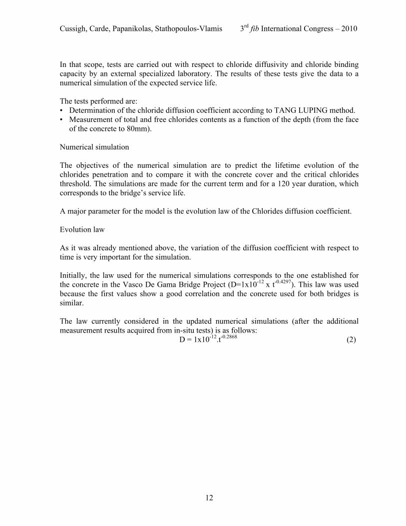
of the concrete to 80mm). Numerical simulation The objectives of the numerical simulation are to predict the lifetime evolution of the chlorides penetration and to compare it with the concrete cover and the critical chlorides threshold. The simulations are made for the current term and for a 120 year duration, which corresponds to the bridge’s service life. A major parameter for the model is the evolution law of the Chlorides diffusion coefficient. Evolution law As it was already mentioned above, the variation of the diffusion coefficient with respect to time is very important for the simulation. Initially, the law used for the numerical simulations corresponds to the one established for the concrete in the Vasco De Gama Bridge Project (D=1x10-12 x t-0.4297). This law was used because the first values show a good correlation and the concrete used for both bridges is similar. The law currently considered in the updated numerical simulations (after the additional measurement results acquired from in-situ tests) is as follows:
D = 1x10-12.t-0.2868 (2)
Cussigh, Carde, Papanikolas, Stathopoulos-Vlamis 3rd fib International Congress – 2010
13
Fig. 4 Evolution of the diffusion coefficient with time
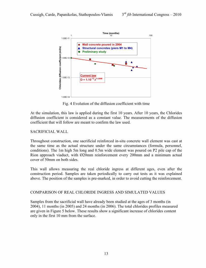
At the simulation, this law is applied during the first 10 years. After 10 years, the Chlorides diffusion coefficient is considered as a constant value. The measurements of the diffusion coefficient that will follow are meant to confirm the law used. SACRIFICIAL WALL Throughout construction, one sacrificial reinforced in-situ concrete wall element was cast at the same time as the actual structure under the same circumstances (formula, personnel, conditions). The 1m high 5m long and 0.5m wide element was poured on P2 pile cap of the Rion approach viaduct, with Ø20mm reinforcement every 200mm and a minimum actual cover of 50mm on both sides. This wall allows measuring the real chloride ingress at different ages, even after the construction period. Samples are taken periodically to carry out tests as it was explained above. The position of the samples is pre-marked, in order to avoid cutting the reinforcement. COMPARISON OF REAL CHLORIDE INGRESS AND SIMULATED VALUES Samples from the sacrificial wall have already been studied at the ages of 3 months (in 2004), 11 months (in 2005) and 24 months (in 2006). The total chlorides profiles measured are given in Figure 5 below. These results show a significant increase of chlorides content only in the first 10 mm from the surface.
Cussigh, Carde, Papanikolas, Stathopoulos-Vlamis 3rd fib International Congress – 2010
14
Fig. 5 Evolution of total chlorides contents with time
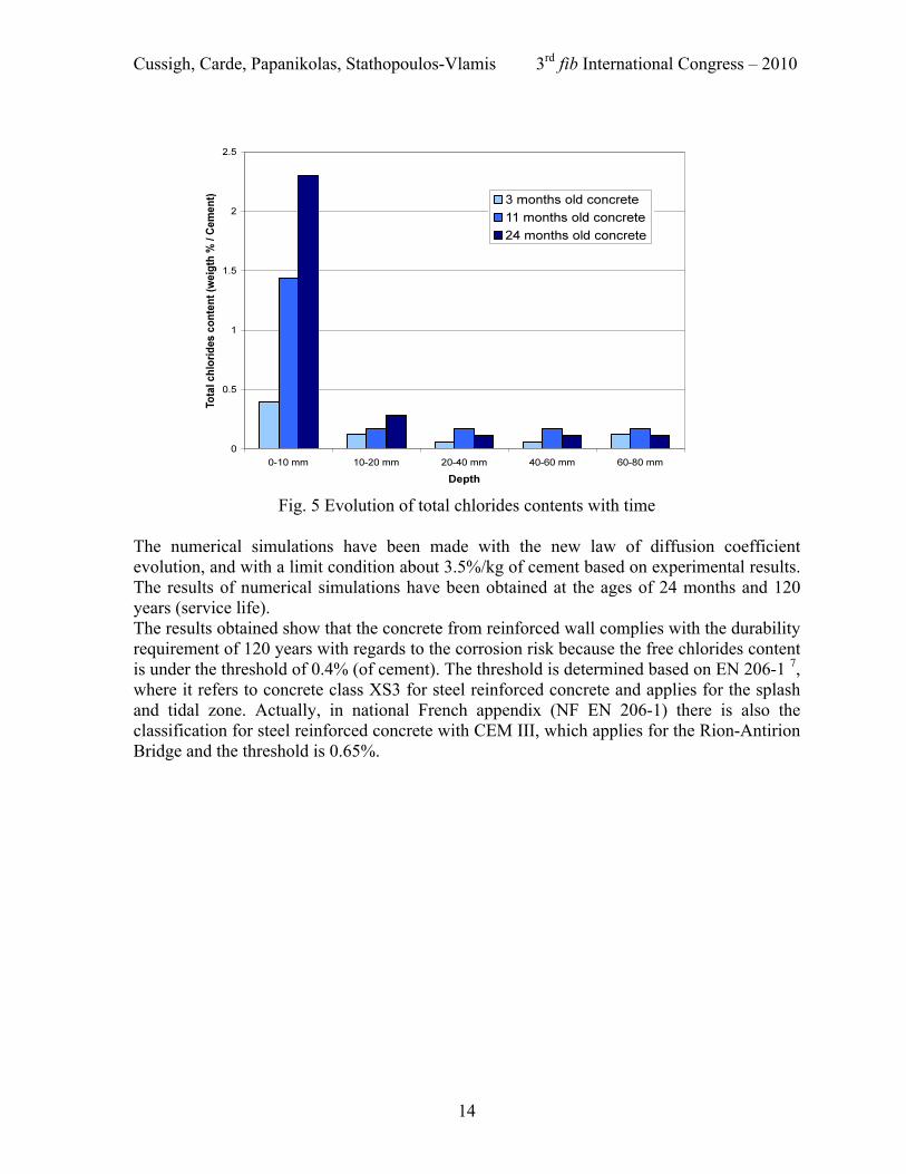
The numerical simulations have been made with the new law of diffusion coefficient evolution, and with a limit condition about 3.5%/kg of cement based on experimental results. The results of numerical simulations have been obtained at the ages of 24 months and 120 years (service life). The results obtained show that the concrete from reinforced wall complies with the durability requirement of 120 years with regards to the corrosion risk because the free chlorides content is under the threshold of 0.4% (of cement). The threshold is determined based on EN 206-1 7, where it refers to concrete class XS3 for steel reinforced concrete and applies for the splash and tidal zone. Actually, in national French appendix (NF EN 206-1) there is also the classification for steel reinforced concrete with CEM III, which applies for the Rion-Antirion Bridge and the threshold is 0.65%.
Cussigh, Carde, Papanikolas, Stathopoulos-Vlamis 3rd fib International Congress – 2010
15
Fig. 6 Simulation for 2 years old concrete compared to the chlorides contents measured (Solid line) and simulation at 120 years (dashed line) for a limit condition equal to 3.5%
CONCLUSIONS Concrete results obtained at laboratory and on site show a very good ability of Rion-Antirion Bridge concrete to protect the embedded steel from corrosion, and guarantee the achievement of a 120 years service life. A follow up of in situ concrete with same testing has been carried out 3 times during the first two years of operation and it will be continued over the next years to confirm its quality towards durability requirements and obtain more results allowing a safer assessment of service life. REFERENCES 1. ASTM C 1202 Standard Test Method for Electrical Indication of Concrete's Ability to
Resist Chloride Ion Penetration 2. ISO 7031 Concrete hardened; determination of the depth of penetration of water under
pressure 3. NT Build 492: CTH Rapid Test 4. Conception des bétons pour une durée de vie donnée des ouvrages
Guide pour la mise en œuvre d’une approche performantielle et prédictive sur la base d’indicateur de durabilité. Documents scientifiques et techniques de l’AFGC (Association Française de Génie-Civil) - Juillet 2004
Cussigh, Carde, Papanikolas, Stathopoulos-Vlamis 3rd fib International Congress – 2010
16
5. Houdusse O., Hornain H. and Martinet G. (2000) Prediction of Long-Term Durability of Vasco Da Gama Bridge in Lisbon. Fifth International Conference of CANMET/ACI. Barcelona. 1037.
6. Odd E. Gjørv and Rui Miguel Ferreira (2002) Rion Antirion Bridge Report. Confidential report
7. EN 206-1: Concrete – Part 1: Specification, performance, production and conformity AKNOWLEDGEMENTS 1. LERM: External specialized laboratory. 2. MacBeton Hellas: Supplier for concrete admixtures, such as Glenium, Pozzolith,
Rheobuilt, etc. 3. Chryso: Supplier for concrete admixtures, such as Optima 100. 4. TITAN: Cement supplier. 5. Lafarge Araxos: Aggregates supplier.