rish con p conventional - КИП плюс - … instruments pvt.ltd. f-31, midc, satpur, nashik-422...
TRANSCRIPT
RISHABH INSTRUMENTS PVT.LTD.F-31, MIDC, Satpur, Nashik-422 007,India.Tel.: +91 253 2202160, 2202202 Fax : +91 253 2351064E-mail : India :- [email protected] International :- [email protected]
Application :
Salient Features :
True RMS measurement.
Fully onsite programmable input voltage range & input current range
On Site Configurable as Active / Reactive / Apparent Transducer / Phase Angle / Power Factor .
Onsite selectable output type(DC current / DC voltage).
Single or Dual output.
Accuracy Class 0.2 ( IEC / EN 60688) for Power .Accuracy Class 0.5 ( IEC / EN 60688) for Phase Angle / Power Factor.
Seven Segment LCD Display.
Rs485(Modbus) Communication.
Wide Auxiliary power supply. Accepts any input between 60V-300V AC/DC or 24V-60V AC/DC.
Output Response Time < 750 ms standard.
Fast and easy installation on DIN RAIL or onto a wall
Display Module(Optional):Optional 7 segment LCD display with backlit & keypad. For displaying measured parameter & onsite configuration of Input/output.
RS485 Communication(Optional):Optional RS485 communication is available. For readingmeasured parameter & onsite configuration of input/output.
Product Features:
Measuring Input: AC Voltage/Current input signal,sine wave or distorted wave form.
Analog Output (Single or dual): Isolated analog output which can be set to voltage or currentoutput onsite.
Accuracy:Output signal accuracy class 0.2 as per International IEC / EN 60688 Standard.
Programmable Input/Output:The Transducer can be programmed onsite using front key & display or through programming port (COM) or through RS 485.
LED Indication:LED indication for power on and output type. (Current output : Red LED, Voltage output : Green LED).
Symbols and their meaning:
X Input
Apparent /Active/Reactive
Power Factor / Phase Angle
X0 Start value of input
X1 Elbow value of input
X2 End value of input
Y Output DC Voltage / DC Current
Y0 Start value of output DC
Voltage / DC Current
Y1 Elbow value of output DC
Voltage / DC Current
Y2 End value of output DC
Voltage / DC Current
RN Rated value of output burden
FN Nominal Frequency
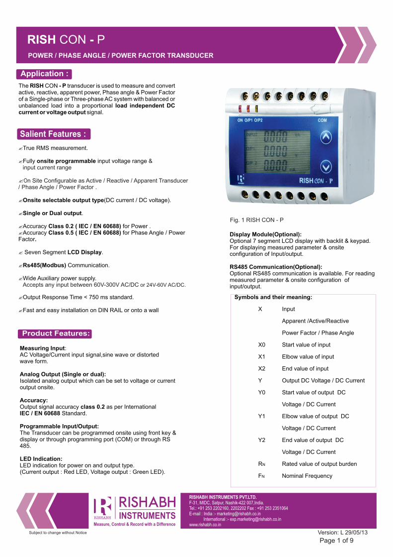
The RISH CON - P transducer is used to measure and convert active, reactive, apparent power, Phase angle & Power Factor of a Single-phase or Three-phase AC system with balanced or unbalanced load into a proportional load independent DC current or voltage output signal.
RISH CON - PPOWER / PHASE ANGLE / POWER FACTOR TRANSDUCER
Subject to change without Notice
Page 1 of 9Version: L 29/05/13
Fig. 1 RISH CON - P
RISHABH INSTRUMENTS PVT.LTD.F-31, MIDC, Satpur, Nashik-422 007,India.Tel.: +91 253 2202160, 2202202 Fax : +91 253 2351064E-mail : India :- [email protected] International :- [email protected]
Technical Specifications:
RISH Ducer VT25 / CT25 TransducerRISH Ducer VT25 / CT25 Transducer RISH Ducer VT25 / CT25 Transducer
Measured Parameter Active Power / Reactive Power / Apparent Power / Power Factor /Phase Angle.
Network Type Supported by Power transducer: Single Phase / 3 phase 3 wire Unbalanced / 3 phase 4 wire Unbalanced 3 phase 3 wire balanced / 3 phase 4 wire balanced
Network Type Supported by Power Factor & Phase Angle : Single Phase / (U12 I1) 3 Phase Balanced load (U13 I1) 3 Phase Balanced load / (U23 I1) 3 Phase Balanced load 3 phase 3 wire balanced / 3 Phase 4 wire Balanced load
Nominal Voltage Input(UN):
Nominal input Voltage (AC RMS) 100 V ≤ UN ≤ 500 VL-L(PT Secondary range)
PT Primary range 100V to 692 KVL-L
Nominal Frequency FN 25 Hz to 60 Hz Nominal input Voltage burden < 0.6 VA per phase at UN
Overload Capacity: 1. UN continuously,2 *
2 * 1 second, repeated 10 times at 10 intervals UN for minute
(Un maximum 300V with power supply powered from measuring input). Nominal Current Input(IN):
Nominal input Current (AC RMS) 1 A ≤ IN ≤ 5 A(CT Secondary range)
CT Primary range 1 A to 9999 A
Nominal Frequency FN 25 Hz to 60 Hz
Nominal input Current burden < 0.2 VA per phase at IN Overload Capacity: IN continuously, 1.2 *
0 * 3 second, repeated 5 times at 5 intervals.1 IN for minute
0 * 1 second, repeated 1 times at 1 hour interval ( ax 250 A).5 IN for M
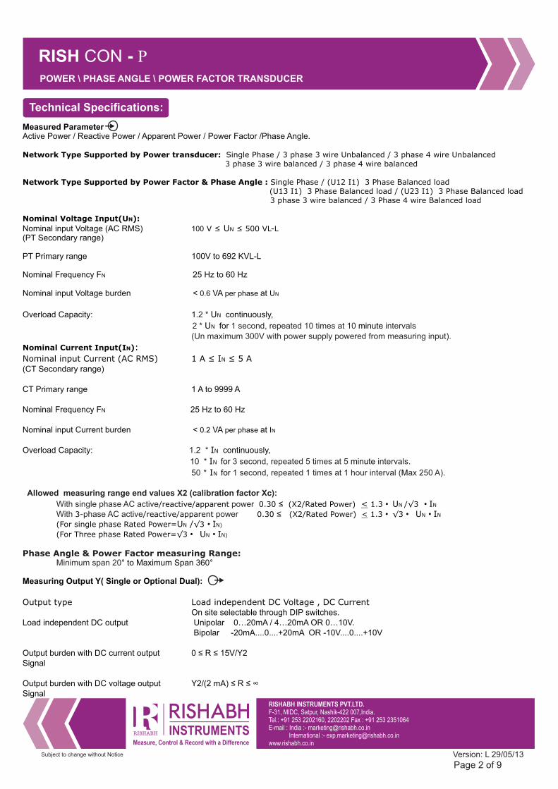
Allowed measuring range end values X2 (calibration factor Xc):
/reactive/apparent 0.30 ≤ (X2/Rated Power) < 1.3 • UN /√3 • IN With single phase AC active power With phase AC active power 3- /reactive/apparent 0.30 ≤ (X2/Rated Power) < 1.3 • √3 • UN • IN
(For single phase Rated Power=UN /√3 • IN)
(For Three phase Rated Power=√3 • UN • IN)
Phase Angle & Power Factor measuring Range: Minimum span 20° to Maximum Span 360° Measuring Output Y( Single or Optional Dual):
Output type Load independent DC Voltage , DC Current On site selectable through DIP switches.Load independent DC output Unipolar 0…20mA / 4…20mA OR 0…10V. Bipolar -20mA....0....+20mA OR -10V....0....+10V
Output burden with DC current output 0 ≤ R ≤ 15V/Y2 Signal
Output burden with DC voltage output Y2/(2 mA) ≤ R ≤ ∞ Signal
RISH CON - P
Subject to change without Notice
Page 2 of 9
POWER \ PHASE ANGLE \ POWER FACTOR TRANSDUCER
Version: L 29/05/13
RISHABH INSTRUMENTS PVT.LTD.F-31, MIDC, Satpur, Nashik-422 007,India.Tel.: +91 253 2202160, 2202202 Fax : +91 253 2351064E-mail : India :- [email protected] International :- [email protected]
RISH Ducer VT25 / CT25 Transducer
Current limit under overload R=0 ≤ 1.25 * Y2 with current output ≤ 100 mA with voltage output
Voltage limit under R=∞ < 1.25 * Y2 with voltage output ≤ 30 V with current output
Residual Ripple in Output signal ≤ 1% pk-pk Response Time < 750 ms
RISH CON - P
Subject to change without Notice
Auxiliary Power Supply:
60V… 300 VAC-DC ± 5% or 24V...60V VAC-DC ± 10%
40 to 65 Hz
Accuracy :( Acc. to IEC / EN 60688)
Reference Value Output end Value Y2 (Voltage or Current)
Basic Accuracy for power transducer 0.2*C
Basic Accuracy for Phase Angle & Power Factor transducer 0.5*C
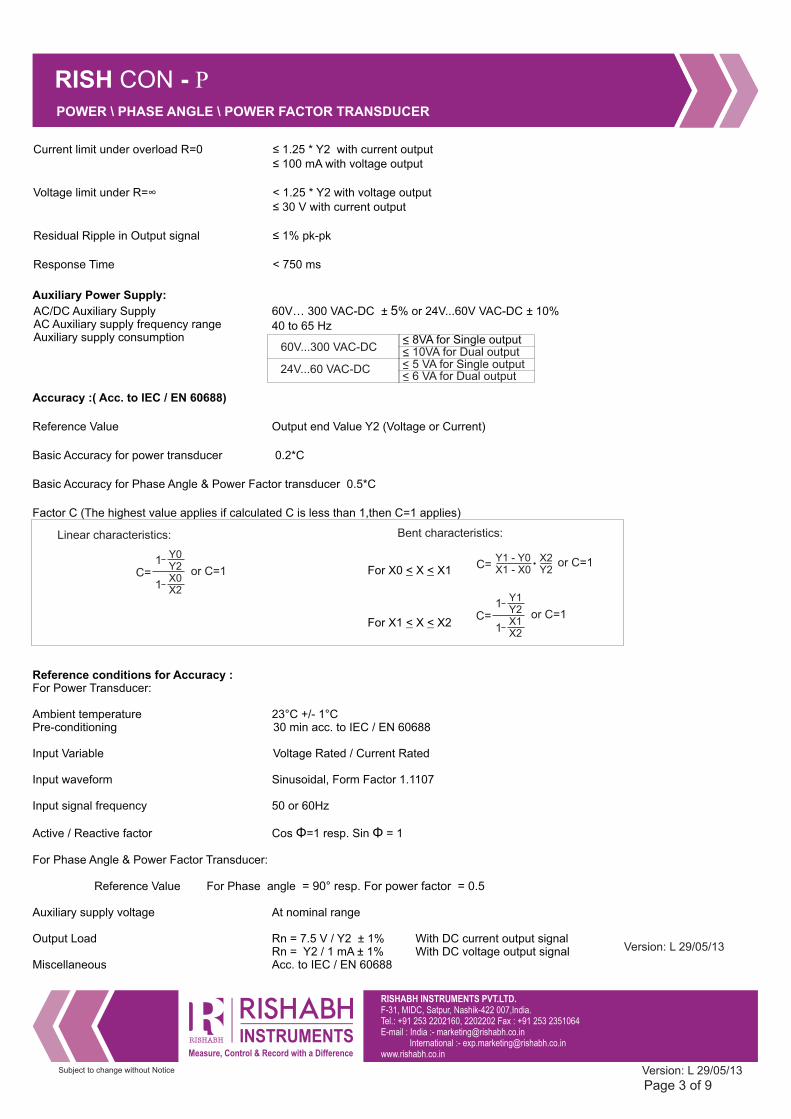
Factor C (The highest value applies if calculated C is less than 1,then C=1 applies)
For X0 < X < X1
For X1 < X < X2
Reference conditions for Accuracy :For Power Transducer:
Ambient temperature 23°C +/- 1°CPre-conditioning 30 min acc. to IEC / EN 60688
Input Variable Voltage Rated / Current Rated
Input waveform Sinusoidal, Form Factor 1.1107
Input signal frequency 50 or 60Hz
Active / Reactive factor Cos Φ=1 resp. Sin Φ = 1
For Phase Angle & Power Factor Transducer:
Reference Value For Phase angle = 90° resp. For power factor = 0.5
Auxiliary supply voltage At nominal range
Output Load Rn = 7.5 V / Y2 ± 1% With DC current output signal Rn = Y2 / 1 mA ± 1% With DC voltage output signalMiscellaneous Acc. to IEC / EN 60688
Page 3 of 9
C=Y1 - Y0 X2X1 - X0 Y2
or C=1
C=
Y1Y2X1X2
1
1or C=1
Y0Y2X0X2
1
1or C=1C=
Linear characteristics: Bent characteristics:
POWER \ PHASE ANGLE \ POWER FACTOR TRANSDUCER
Version: L 29/05/13
AC/DC Auxiliary Supply AC Auxiliary supply frequency range Auxiliary supply consumption
Version: L 29/05/13
< 8VA for Single output< 10VA for Dual output60V...300 VAC-DC
24V...60 VAC-DC < 5 VA for Single output< 6 VA for Dual output
RISHABH INSTRUMENTS PVT.LTD.F-31, MIDC, Satpur, Nashik-422 007,India.Tel.: +91 253 2202160, 2202202 Fax : +91 253 2351064E-mail : India :- [email protected] International :- [email protected]
RISH CON - P
Subject to change without Notice
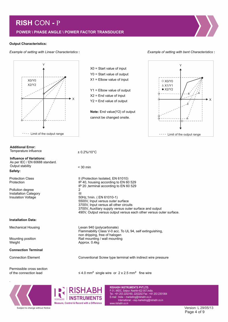
Output Characteristics:
Example of setting with Linear Characteristics : Example of setting with bent Characteristics :
Y
X
X0/Y0
X1/Y1
Limit of the output range
X2/Y2
Y
X
X0/Y0
X2/Y2
Limit of the output range
± 0.2%/10°C
< 30 minSafety:
Protection Class II (Protection Isolated, EN 61010)Protection IP 40, housing according to EN 60 529 IP 20 ,terminal according to EN 60 529Pollution degree 2Installation Category IIIInsulation Voltage 50Hz,1min. ( EN 61010-1) 5500V, Input versus outer surface 3700V, Input versus all other circuits 3700V, Auxiliary supply versus outer surface and output 490V, Output versus output versus each other versus outer surface.
Installation Data:
Mechanical Housing Lexan 940 (polycarbonate) Flammability Class V-0 acc. To UL 94, self extinguishing, non dripping, free of halogenMounting position Rail mounting / wall mountingWeight Approx. 0.4kg
Connection Terminal
Connection Element Conventional Screw type terminal with indirect wire pressure
Permissible cross section of the connection lead ≤ 4.0 mm² single wire or 2 x 2.5 mm² fine wire
.
Page 4 of 9
POWER \ PHASE ANGLE \ POWER FACTOR TRANSDUCER
Version: L 29/05/13
X0 = Start value of input
Y0 = Start value of output
X1 = Elbow value of input
Y1 = Elbow value of output
X2 = End value of input
Y2 = End value of output
Note: End value(Y2) of output
cannot be changed onsite.
Additional Error:Temperature influence
Influence of Variations: As per IEC / EN 60688 standard.Output stability
RISHABH INSTRUMENTS PVT.LTD.F-31, MIDC, Satpur, Nashik-422 007,India.Tel.: +91 253 2202160, 2202202 Fax : +91 253 2351064E-mail : India :- [email protected] International :- [email protected]
RISH CON - P
Subject to change without Notice
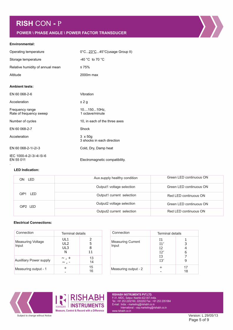
Environmental:
Operating temperature 0°C...23°C...45°C(usage Group II)
Storage temperature -40 °C to 70 °C
Relative humidity of annual mean ≤ 75%
Altitude 2000m max
Ambient tests:
EN 60 068-2-6 Vibration
Acceleration ± 2 g
Frequency range 10....150...10Hz, Rate of frequency sweep 1 octave/minute
Number of cycles 10, in each of the three axes
EN 60 068-2-7 Shock
Acceleration 3 x 50g 3 shocks in each direction
EN 60 068-2-1/-2/-3 Cold, Dry, Damp heat
IEC 1000-4-2/-3/-4/-5/-6EN 55 011 Electromagnetic compatibility..
Measuring Voltage Input
Auxilliary Power supply
Measuring output - 1
13 14
15 16
UL1UL2UL3N
+ -
Electrical Connections:
Green LED continuous ONAux.supply healthy condition
O/P2 LED
O/P1 LED
ON LED
Output1 voltage selection
Output1 current selection
Output2 voltage selection
Output2 current selection
Green LED continuous ON
Red LED continuous ON
Green LED continuous ON
Red LED continuous ON
Connection Terminal details
LED Indication:
Measuring Current Input
Measuring output - 2
I1 I1’I2 I2’I3 I3’
~ , + ~ , -
+ -
Connection Terminal details
17 18
Page 5 of 9
POWER \ PHASE ANGLE \ POWER FACTOR TRANSDUCER
Version: L 29/05/13
25811
134 679
RISHABH INSTRUMENTS PVT.LTD.F-31, MIDC, Satpur, Nashik-422 007,India.Tel.: +91 253 2202160, 2202202 Fax : +91 253 2351064E-mail : India :- [email protected] International :- [email protected]
RISH CON - P
Subject to change without Notice
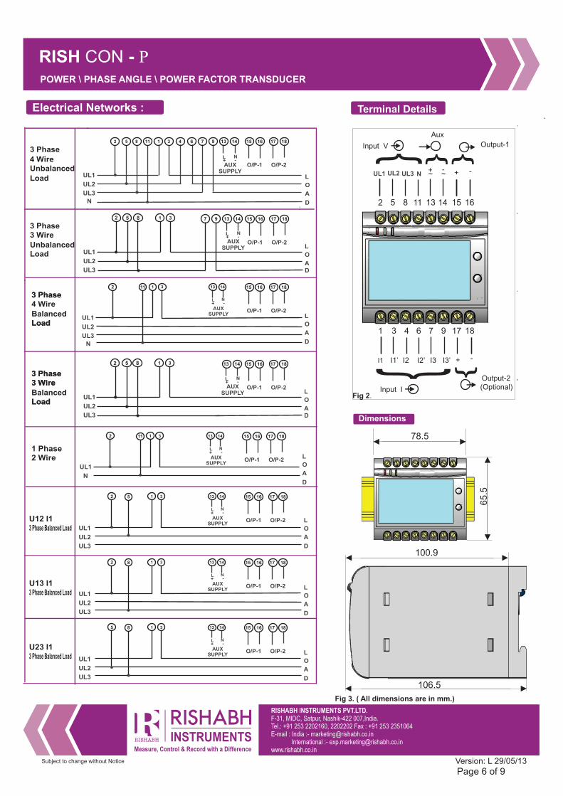
Terminal DetailsElectrical Networks :
3 Phase 4 Wire Unbalanced
Load
3 Phase 3 Wire
Unbalanced Load
D
2 5 8 11 1 3 4 6 7 9 13 14
L N
AUXSUPPLY
+ -
L
O
A
D
15 16 17 18
O/P-1 O/P-2
5 8 1 3
L N
AUXSUPPLY
7 9 13 14
+ -
L
O
A
15 16 17 18
O/P-1 O/P-2
L N
AUXSUPPLY
13 141 3112
+ -
L
O
A
D
15 16 17 18
O/P-1 O/P-2
2 5 8 11 13 14 15 16
1 3 4 6 7 9 17 18
~+
~- + -
I1 I1’ I2 I2’ I3 I3’ + -
{ { {
{ {
Output-1
Output-2(Optional)Input I
Input V
Aux
Page 6 of 9
U12 I1
3 Phase Balanced Load
L N
AUXSUPPLY
13 141 352
+ -
L
O
A
D
15 16 17 18
O/P-1 O/P-2
UL2
UL3
N
UL1
UL2
UL3
UL1
UL2
UL3
N
UL1
UL2
UL3
UL1
U13 I1
3 Phase Balanced Load
Application : Application : Application : Application :
Dimensions
78.5
65
.5
L N
AUXSUPPLY
13 141 382
+ -
L
O
A
D
15 16 17 18
O/P-1 O/P-2
UL2
UL3
UL1
U23 I1
3 Phase Balanced Load
L N
AUXSUPPLY
13 141 385
+ -
L
O
A
D
15 16 17 18
O/P-1 O/P-2
UL2
UL3
UL1
POWER \ PHASE ANGLE \ POWER FACTOR TRANSDUCER
Version: L 29/05/13
UL1 UL2 UL3 N
106.5
100.9
2
D
5 8 1 3
L N
AUXSUPPLY
13 14
+ -
L
O
A
15 16 17 18
O/P-1 O/P-2
UL2
UL3
UL1
2
3 Phase 3 Wire
Balanced Load
3 Phase3 Wire
Load
3 Phase4 Wire
Balanced Load
3 Phase
Load
1 Phase2 Wire
L N
AUXSUPPLY
13 141 3112
+ -L
O
A
D
15 16 17 18
O/P-1 O/P-2
N
UL1
Fig 2.
Fig 3. ( All dimensions are in mm.)
RISHABH INSTRUMENTS PVT.LTD.F-31, MIDC, Satpur, Nashik-422 007,India.Tel.: +91 253 2202160, 2202202 Fax : +91 253 2351064E-mail : India :- [email protected] International :- [email protected]
RISH CON - P
Subject to change without Notice
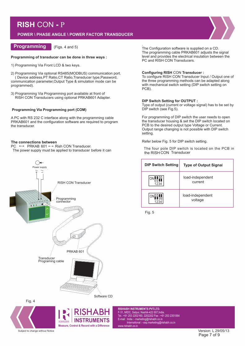
Electricannections:Programming (Figs. 4 and 5)
Programming of transducer can be done in three ways :
1) Programming Via Front LCD & two keys.
2) Programming Via optional RS485(MODBUS) communication port. ( Device address,PT Ratio,CT Ratio,Transducer type,Password, communication parameter,Output Type & simulation mode can be programmed).
3) Programming Via Programming port available at front of RISH CON Transducers using optional PRKAB601 Adapter.
Programming Via Programming port (COM)
A PC with RS 232 C interface along with the programming cablePRKAB601 and the configuration software are required to program the transducer.
The connections betweenPC PRKAB 601 Rish CON Transdu. cer.The power supply must be applied to transducer b e fore it can
1234
ON
1234
ON load-independentcurrent
load-independentvoltage
Fig. 5
The four pole DIP switch is located on the PCB inthe RISH CON Transducer
DIP switches Type ofoutput signal
.The Configuration software is supplied on a CD.The programming cable PRKAB601 adjusts the signal level and provides the electrical insulation between the PC and RISH CON Transducers.
Configuring RISH CON Transducer :To configure RISH CON Transducer Input / Output one of the three programming methods can be adapted along with mechanical switch setting (DIP switch setting on PCB).
DIP Switch Setting for OUTPUT :Type of output (current or voltage signal) has to be set byDIP switch (see Fig.5).
For programming of DIP switch the user needs to openthe transducer housing & set the DIP switch located on PCB to the desired output type Voltage or Current.Output range changing is not possible with DIP switch setting.
Refer below Fig. 5 for DIP switch setting.
1615141311852
PRKAB 601
Programmingconnector
Power supply
Transducer Programing cable
Software CD
RISH CON Transducer
Type of Output SignalDIP Switch Setting
Page 7 of 9
POWER \ PHASE ANGLE \ POWER FACTOR TRANSDUCER
Version: L 29/05/13
Fig. 4
RISHABH INSTRUMENTS PVT.LTD.F-31, MIDC, Satpur, Nashik-422 007,India.Tel.: +91 253 2202160, 2202202 Fax : +91 253 2351064E-mail : India :- [email protected] International :- [email protected]
RISH CON - P
Subject to change without Notice
Page 8 of 9Version: L 29/05/13
POWER \ PHASE ANGLE \ POWER FACTOR TRANSDUCER
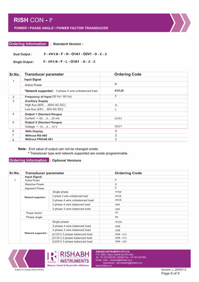
Ordering Information : Standard Version :
2 Frequency of Input (50 Hz / 60 Hz) F
Current = -20.....0.....20 mA
4 Output 1 (Standard Ranges)
O1A1
5 Output 2 (Standard Ranges)
Voltage = -10.....0.....10 V O2V1
End value of output can not be changed onsite.
* Transducer type and network supported are onsite programmable.
Sr.No. Ordering CodeTransducer parameter
1Input Signal
4WUB3 phase 4 wire unbalanced load
Active Power
*Network supported :
Note:
Dual Output :
Z
6
7
8
With Display
Without RS-485
Without PRKAB 601
D
Z
P - 4WUB - F - H - O1A1 - O2V1 - D - Z - Z
Single Output : P - 4WUB - F - L - O1A1 - D - Z - Z
P
Electricannections:Ordering Information : Optional Versions
Sr.No. Ordering CodeTransducer parameter
1Input Signal
(U23I1) 3 phase balanced load
Phase angle
*Network supported :
(U12I1) 3 phase balanced load
(U13I1) 3 phase balanced load
3 phase 4 wire balanced load
3 phase 3 wire balanced load
3 phase 4 wire unbalanced load
Active Power
*Network supported : 3 phase 3 wire unbalanced load
3 phase 4 wire balanced load
3 phase 3 wire balanced load
P
1P2W
3WUB
4WUB
4WB
3WB
PA
Single phase
Single phase/
4WB
3WB
1P2W
3WB - U12
3WB - U13
3WB - U23
Power factor/ PF
Reactive Power
Apparent Power
Q
S
3 Auxiliary Supply
High Aux (60V.....300V AC-DC)
Low Aux (24V.....60V AC-DC)
H
L
RISHABH INSTRUMENTS PVT.LTD.F-31, MIDC, Satpur, Nashik-422 007,India.Tel.: +91 253 2202160, 2202202 Fax : +91 253 2351064E-mail : India :- [email protected] International :- [email protected]
RISH CON - P
Subject to change without Notice
Page 9 of 9Version: L 29/05/13
POWER \ PHASE ANGLE \ POWER FACTOR TRANSDUCER
6 LCD display module
Without Display
D
RS-485 module
Without PRKAB 601
R
7
PRKAB 601module
PR
8
Without RS-485
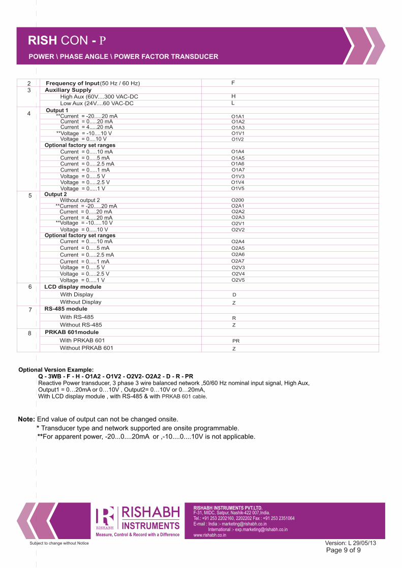
2 Frequency of Input(50 Hz / 60 Hz)
Current = 4.....20 mA
Current = 0.....10 mA Current = 0.....5 mA
Current = 0.....2.5 mA
Voltage = 0.....10 V
Voltage = 0.....5 V
Voltage = 0.....1 V
Current = 0.....1 mA
O200
O2V2
O2A4
O2A5
O2A6
O2A7
O2V4
5 Output 2
O2V3
Optional factory set ranges
Current = 4.....20 mA
Current = 0.....10 mA Current = 0.....5 mA Current = 0.....2.5 mA
Voltage = 0....10 V
Voltage = 0.....5 V
Voltage = 0.....1 V
Current = 0.....1 mA
O1A3 O1V1
O1A4
O1A5O1A6
O1A7
O1V5
4Output 1
O1V3
Optional factory set ranges
Without output 2
O2A2
With Display
Z
With RS-485
With PRKAB 601
Z
Z
Current = 0.....20 mA O1A1
Current = 0.....20 mAO2A1
Voltage = 0.....2.5 V O1V4
Voltage = 0.....2.5 V O2V5
**Voltage = -10....10 V
**Current = -20.....20 mA O1A2
O1V2
**Voltage = -10.....10 V
**Current = -20.....20 mA
O2A3
O2V1
F
Optional Version Example: Q - 3WB - F - H - O1A2 - O1V2 - O2V2- O2A2 - D - R - PR Reactive Power transducer, 3 phase 3 wire balanced network ,50/60 Hz nominal input signal, High Aux, Output1 = 0…20mA or 0…10V , Output2= 0…10V or 0…20mA, With LCD display module , with RS-485 & with .PRKAB 601 cable
**For apparent power, -20...0....20mA or ,-10....0....10V is not applicable.
Note: End value of output can not be changed onsite.
* Transducer type and network supported are onsite programmable.
3
Low Aux (24V....60 VAC-DC LHigh Aux (60V....300 VAC-DC H
Auxiliary Supply