risk models for evaluation and type classification of...
TRANSCRIPT

Bilal M. Ayyub1Professor
Center for Technology and Systems Management,University of Maryland,
College Park, MD 20742e-mail: [email protected]
Samuel WehrStandards and Regulations,
Mustang Survival Corporation,Burnaby, BC, Canada
e-mail: [email protected]
Risk Models for Evaluation andType Classification of PersonalFlotation DevicesThis paper presents proposed models for assessing the aggregate performance of personalflotation devices (PFDs) by using risk methods. The aggregate performance is used toquantify the probability of a PFD saving lives following marine events. The models providea formal structure and consistency to an approval process for new and novel engineeringdesigns of such devices. They can also aid in identifying critical factors for evaluating theminimum level of performance necessary for approval. Such models could complement andenhance current standards and could result in significant safety improvements through theimplementation of new technologies and designs. Such models could also aid in evaluatingother new and innovative classes of engineering designs and designs for special needs.Also, they encourage creativity in system design by increasing the design domain andprovide an overall performance measure allowing for trade-off analysis. The models canultimately provide guidance in the development of future standards. The risk-based modelsconsist of three recommended computational procedures for inherently buoyant, inflatable,and hybrid PFDs. Special panels of experts from the CORD Group, Canada, the U.S. CoastGuard (USCG), Underwriters Laboratories (UL), IMANNA Laboratories, Inc., and PFDManufacturing Association (PFDMA) evaluated these models and provided recommendedvalues by using formal expert opinion elicitation. [DOI: 10.1115/1.4026399]
Keywords: life jackets, personal flotation devices, drowning, human life, compliance,standards, decision making, flotation, rescue, lifesaving
1 Introduction
1.1 Accidents and Fatalities. The USCG compiles statisticsevery year on reported recreational boating accidents on the basisof accident reports filed by people involved in these accidents andproduces an annual boating statistics publication. The 2011 USCGpublication [1] reports 4588 accidents involving 758 deaths, 3081injuries, and approximately $52 million in damage to propertyfrom these accidents. The reported fatality rate was 6.2 deathsper 100,000 registered recreational vessels; there were 12,173,935recreational vessels registered. Seventy percent of all fatal boatingaccident victims drowned, 84% of whom were reported as notwearing a life jacket or PFD. Eighty percent of those who drownedwere using vessels less than 21 ft long. In 16% of deaths, alcoholuse was the leading contributing factor. Sixty percent of thechildren fatalities were from drowning, with 78% of those whodrowned were reportedly wearing life jackets as required by stateand federal law. The most common types of vessels involved inreported accidents were open motorboats (47%), personal water-craft (19%), and cabin motorboats (14%). It is noteworthy that nineout of ten drowning cases occur in inland waters, on days of goodweather, and most within a few feet of safety (see Table 1). Tragi-cally, most drowning victims had access to a PFD but did notwear it.
1.2 PFD Regulations, Standards and Design Domains.The design, manufacturing and in-water performance of PFDsare regulated by the USCG and standardized through consensusby stakeholders from the industry, the government, test and stan-dards organizations, safety organizations, commercial users, supplychain, consumers, and general interest. The PFD standards in theUnited States are managed by UL, with standards such as UL
1123 [2], UL 1180 [3], and UL 1517 [4]. Personal flotation devicesare tested for performance by USCG-certified laboratories beforetheir USCG approval for use. Moreover, the manufacturing and pro-duction of PFDs are overseen by the same laboratories that conductthe approval testing for USCG-certified manufacturers.
Personal flotation device standards provide guidance and re-quirements on in-water performance and some design aspects ofPFDs to ensure a survival likelihood from drowning that is greaterthan some acceptable levels. Establishing and defining the PFD per-formance characteristics needed to meet this goal for various usersand environments is schematically shown in the partitioned spacesof Fig. 1. Ideally the standards would cover the full area of thefour quadrants, but realistically this is not economically or techno-logically possible; therefore, the regulators and the industry seekto cover universal and unique factors for survival. All PFD de-signs should address common factors based on “universal needs”as shown in the figure, e.g., minimize the time that breathing is im-peded. In some circumstances, some PFDs must also address spe-cial conditions indicated as “universal needs and unique conditions”in the figure, e.g., thermal protection needs, special restraint or re-covery harness, or needs of a broader range of body types than themajority of the population. Acceptable performance becomes a var-iable based on the different users, environments, and applicationsfor the PFDs, or on the combined performance according to severalindividual test characteristics. The current state of PFD require-ments as defined by governing standards, called “possible statesper current PFD standards” in the figure, should be assessed incomparison with the “universal needs and unique conditions.” Thefigure also includes “unfeasible conditions” to identify the spaceoutside the “universal needs including unique conditions” space,e.g., swift water entrapment. To define these needs and the signifi-cance of the specific requirements for PFD performance, risk andreclassification (PFDRRA) models are proposed in this paper toaggregate in-water effectiveness of PFDs. In this paper, they arecalled PFDRRA models.
1Corresponding author.Manuscript received April 6, 2014; final manuscript received October 25, 2014;
published online February 27, 2015. Assoc. Editor: Phil Cappel.
ASCE-ASME Journal of Risk and Uncertainty in Engineering Systems,Part B: Mechanical Engineering
MARCH 2015, Vol. 1 / 011007-1Copyright © 2015 by ASME
Downloaded From: http://risk.asmedigitalcollection.asme.org/ on 03/02/2015 Terms of Use: http://asme.org/terms

1.3 Background. The models are derived from event and faulttree modeling of all possible scenarios following a marine event[5–7] and are updated to reflect dependency among underlyingevents [8–10]. These models provide a formal structure and consis-tency to the process of evaluating new and novel approaches to de-signing devices for drowning prevention and designs for specialneeds. They can be used within a risk-based compliance approvalprocess, identifying critical factors for evaluating a PFD’s lifesavingpotential and can be applied to determine the minimum level of per-formance necessary for approval of PFD design by an authorizedtest laboratory or a regulatory agency. Also, they encourage crea-tivity in system design and provide an overall performance measureallowing for trade-off analysis. The models complement and en-hance the current PFD standards and can ultimately provide a basisfor the development of future standards.
The models presented in this paper were calibrated and betatested by users from various industry sectors in 2002 [9]. In several
beta-testing studies, the models were used to evaluate the perfor-mance of specific USCG-approved PFDs to determine implicit life-saving probabilities in these designs. The calibration processenabled the determination of target probabilities based on minimumdesign and performance characteristics of PFDs. The PFDRRAmodels consist of three recommended computational proceduresfor inherently buoyant, inflatable, and hybrid PFDs. A special panelof subject matter experts from the U.S. Coast Guard and Trans-port Canada, industry representatives from the PFD ManufacturerAssociation (PFDMA), Underwriter Laboratories, Inc., IMANNALaboratories, Inc., and others, has evaluated this methodology inseveral workshops of subject matter experts, PFD beta testing, andvalidation [11–14].
1.4 Purpose and Scope. The proposed models are: (1) for thetype evaluation of conventional PFDs, i.e., performance, classifica-tion and aggregation of in-water effectiveness of personal flotationdevices and (2) for evaluation of special-purpose life jackets andbuoyancy aids that perform accordingly for special-use applicationsor provide equivalent performance. These applications and equiv-alences should not reduce essential requirements, such as aggregate
Table 1 Weather and water conditions [1]
Case Item
Accidents Deaths Injuries
4588 758 3081
Type of water body Inland waters (lakes, bays, rivers, etc.) 89.1% 91.4% 89.7%Great lakes, gulf, and oceans 10.9% 8.6% 10.3%Unknown 0.0% 0.0% 0.0%
Water conditions Calm (waves less than 6 in.) 54.1% 49.7% 55.6%Choppy (waves 6 to 24 in.) 28.3% 23.1% 30.1%Rough and very rough 12.0% 14.8% 9.8%Unknown 5.7% 12.4% 4.5%
Wind None 9.2% 12.1% 9.6%Light (0–6 mph) 54.7% 46.4% 60.3%Moderate (7–14 mph) 22.8% 19.0% 21.0%Strong and storm 9.2% 12.9% 5.6%Unknown 4.1% 9.5% 3.4%
Visibility Poor 4.2% 5.7% 4.5%Fair 6.5% 8.3% 5.7%Good 82.0% 74.7% 83.5%Unknown 7.3% 11.4% 6.3%
Water temperature 30°F and below 1.1% 3.6% 1.1%40–49°F 3.0% 8.2% 2.4%50–59°F 8.1% 15.0% 8.0%60–69°F 16.8% 17.7% 15.1%70–79°F 30.0% 19.8% 30.3%80–89°F 24.1% 17.7% 26.5%90°F or above 1.6% 1.2% 2.0%Unknown 15.4% 16.9% 14.6%
Calm water Waves
Swimmers
Non-swimmers
Factors that prevent drowning
Factors that do not prevent drowning
UnfeasibleConditions
Unfeasible Conditions
Unfeasible Conditions
Unfeasible Conditions
Fig. 1 PFD performance, design domain, and standards Fig. 2 An early cork life jacket design of 1861 [15]
011007-2 / Vol. 1, MARCH 2015 Transactions of the ASME
Downloaded From: http://risk.asmedigitalcollection.asme.org/ on 03/02/2015 Terms of Use: http://asme.org/terms

Table 2 Types of personal flotation devices in the United States
PFD device type and image Description
Off-shore life jackets (USCG Type I PFD)
(a) Inherently buoyant vest Type I
Designed for open, rough, or remote waters, where rescue may not be immediate. Such PFDsprovide the most reliable flotation, turn most unconscious wearers face-up, come in highlyvisible colors, and may have reflective material for search and rescue. They are, however, bulkyand could restrict full range of movements needed to enjoy water-related activities and sports.
Near-shore buoyant vests (USCG Type II PFDs)
(b) Inherently buoyant vest Type II
(c) Inflatable vest Type II (deflated)
(d) Inflatable vest Type II (inflated)
Designed for calm or inland water, where fast rescue is likely. Such PFDs turn someunconscious wearers face-up in the water, are less bulky and more comfortable than off-shorelife jackets (Type I PFDs), are approved for multiple sizes from infant through adult, a goodchoice for children, and are suitable for some rough water conditions. They are, however, notrecommended for long hours in rough water and can be uncomfortable or cumbersome foradults to wear. The wearer’s face may often be covered by water from waves.
Flotation aids (USCG Type III PFDs)
(e) Inherently buoyant Type III
(f) Inflatable belt Type III (deflated)
(g) Inflatable vest Type III (deflated and inflated)
Designed for conscious users in calm inland water or where fast rescue is likely. Such PFDs aregenerally the most comfortable for continuous wear, are designed for general boating anddesignated activities marked on the device, and are available in many styles, including vestsand flotation coats. Wearers, however, may have to tilt the head back to avoid being floatedface-down, and these devices are not recommended for extended survival in rough water.The wearers’ face may often be covered by water from waves.
(h) Throwable devices (USCG IV PFDs) Includes buoys and boat cushions. They function as throwable devices and are not designed tobe worn.
(i) Wearable special-use devices(USCG Type V PFDs)
Includes boardsailing vests, deck suits, pullover vests, work vests, some hybrid PFDs, etc.
All images were provided courtesy of Mustang Survival ULC.
ASCE-ASME Journal of Risk and Uncertainty in Engineering Systems,Part B: Mechanical Engineering
MARCH 2015, Vol. 1 / 011007-3
Downloaded From: http://risk.asmedigitalcollection.asme.org/ on 03/02/2015 Terms of Use: http://asme.org/terms

Pictogram concept (derived from ISO PFD standards)
Descriptive Name
Descriptive definition (Simple, clear descriptions of environment for users)
Open Water (OW) Life jacket
Designed for open, rough or remote water, where rescue may be slow coming:
Most effective for offshore waters. Turns most people from face down to face up. Best chance of survival for unconscious wearer.Enhances detection with features such as highly visible color.
Near Shore (NS) Life jacket
Designed for calm or inland water, or where there is good chance of fast rescue:
Good support for unconscious wearer. Will turn some people from face down to face up. Available for adults and children
Calm water (CW) Buoyancy Aid
Designed for conscious users in calm, inland water, or where rescue is close at hand:
Most comfortable with less bulk, to encourage continuous wear.Many suitable for water sports. Not for smallest children. Will not turn unconscious user from face down to face up.
Fig. 3 Environments for PFDs
Fig. 4 PFD performance evaluation
Table 3 Parameters relating to PFD performance effectiveness for all buoyancy methods and environments
Notation Name Measurement definition
EFF PðEFFjAV;D;RÞ Probability that the PFD is effective given that the PFD is available, donned, and reliable. This event isaffected by the following performance characteristics:
FB Freeboard Distance measured perpendicular to the surface of the water to the lowest point where the wearer’srespiration may be impeded. The model values are based on the average of all subjects tested without anynegative values permitted.
HP Heave period When a subject wearing a PFD, face-up, and in a relaxed position is forcefully submerged in calm water, theheave period is the time it takes the subject to transcend one immersion-emersion cycle. The model value isbased on the result of testing one specific subject.
TT Turning time and ability For life jackets, turning time measures turning ability and is defined as the average time required for adevice to turn face-down wearers to a position in which the wearers’ respiration is not impeded by water,corrected for the percentage of turns [TT ¼ ðAtÞ the average turning time for all tests resulting in a turn x(Ttotal) total number of tests performed/(Tt) the number of tests resulting in a turn].For buoyancy aids, each subject passing the stability test is required to obtain a value of 1 for thischaracteristic. Otherwise, the value is zero, and the device rejected.
FPA Face plane angle The angle, relative to the surface of the water, of the plane formed by the most forward part of the foreheadand chin of a wearer floating in the attitude of static balance. A positive angle is achieved when a user’sforehead is higher than their chin. Model values are based on the average of all subjects tested.
PS Placement security For buoyancy aids the ride-up test is used as a current gauge of the PFD placement security. Ride-up isdefined as the shoulder gap measured between the device and the right shoulder of the subject followingthree self-induced plunging actions in the water while in the vertical position. Model values are based on theaverage of all subjects tested.For life jackets, passing the water entry test is required to obtain a value of 1 for this characteristic.Otherwise, the value is zero, and the device rejected.
DTC Detectability Availability, adequacy, and effectiveness of detection aids for a PFD user, measured as the probability ofdetection of a user by rescuers. Model values are based on the PFD design and certain accessories provided.
011007-4 / Vol. 1, MARCH 2015 Transactions of the ASME
Downloaded From: http://risk.asmedigitalcollection.asme.org/ on 03/02/2015 Terms of Use: http://asme.org/terms

Table 4(a) Parameters for all environments and all PFDs
Notation Name Measurement definition
BME Buoyant material effective The fraction of the adult population for which the buoyant chamber/buoyancy materialwill provide sufficient flotation to keep airway above the surface in calm water andadjusted for various environments.
DA Don PFD after entering the water The probability that the PFD wearer dons a PFD that accounts for the average time todon in calm-water condition and the wearer is a swimmer. DA is outside the scope of thepresent practice, and its values are a multiple of the DP respective values.
DP Don PFD before entering the water The probability that the PFD wearer dons a PFD that accounts for the average time todon before entering water. This probability can be estimated from testing the averagetime to don a PFD out of water.
PMB PFD maintains buoyancy The probability that the PFD maintains buoyancy during usage under the condition thatit survives the marine event. Reliability for the buoyancy chamber and material isestimated by performing a submergence buoyancy test and measuring the loss over time(24 hr) as well as performing the component buoyancy durability tests.
ROC Other components vital to providingbuoyancy operate
Probability that the other components vital to providing buoyancy operate, such asstraps, buckles, adjusters, zips, etc.
SNDF Shell not defective Probability that the shell fabric/material is not defective.SNDMB Shell not defective before entering water Probability that the shell fabric/material is not damaged before entering the water.SNDMA Shell not damaged after entering water Probability that the shell fabric/material is not damaged after entering the water.W Wearability Probability that a PFD is worn during a marine event given that the person has the skills
and knowledge to don before an accident. This probability is affected by the subjectivejudgment of PFD wearers who are influenced by things such as the aesthetics and utilityof the PFD design.
Table 4(b) Parameters for all environments and for only inflatable and hybrid PFDs
Notation Name Measurement definition
AAF Automatic activation functions The automatic activation-inflation system is a system that activates to inflate oneor more PFD compartments upon immersion in water without any action by theuser. This probability can be estimated from the time it takes to automaticallyactivate a PFD once it enters the water.
CASA Gas does not exceed design pressure Probability that the compressed gas does not exceed the burst pressure of thePFD upon activation. The limits shall be established by overpressure testingPFDs to ensure compliance with UL or ISO requirements.
CLPA Cylinder properly loaded (auto-inflation) Probability that the gas cylinder is properly loaded for automatic activation. Thisprobability should account for the presence of a cylinder seal indication device.
CLPM Cylinder properly loaded (manual) Probability that the gas cylinder is properly loaded for manual activation. Thisprobability should account for the presence of a cylinder seal indication device.
CNDA Cylinder not defective (auto-inflation) Probability that the cylinder is not defective to properly inflate for automaticactivation.
CNDM Cylinder not defective (manual) Probability that the cylinder is not defective to properly inflate for manualactivation.
CNPAA Cylinder not activated (auto-inflation) Probability that the cylinder was not previously activated for automatic inflation.This probability should account for the use of cylinder seal indication.
CNPAM Cylinder not previously activated (manual) Probability the cylinder was not previously activated for manual activation. Thisprobability should account for the use of cylinder seal indication.
MAMF Manual device functions before entering water Probability that the manual activation functions before entering the water. Thisprobability accounts for several events including the probability of mechanicaldevice functions (MDF) and the probability that the wearer activates the device(PACB). It can be estimated from the time it takes an individual to manuallyactivate the PFD while out of the water.
MAMFA Manual device functions after entering water Probability that the manual activation functions after entering the water. Thisprobability accounts for several events including the mechanical devicefunctions after entering the water (MDFA) and the probability that the weareractivates the device after entering the water. This probability can be estimatedfrom the time it takes an individual to manually activate the PFD while in thewater.
MAWA Mouth activation using oral inflator(after entering water)
Probability that the oral inflation system functions, accounting for several eventsincluding the probability that the mechanical mouth activation system functionsand the probability that the person has the knowledge to activate the PFD. Thiscan be estimated from the time it takes an individual to orally inflate the PFD inthe water to obtain positive freeboard.
MAWB Mouth activation using oral inflator(before entering water)
Probability that the oral inflation system functions, accounting for several eventsincluding the probability that the mechanical mouth activation system functionsand the probability that the person has the knowledge to activate the PFD. Thiscan be estimated from the time it takes an individual to orally inflate the PFD outof the water to obtain positive freeboard when used in water.
RVF Relief valve functions Probability that the relief valve is functioning properly. This parameter can beestimated from laboratory tests of the valve’s crack pressure.
ASCE-ASME Journal of Risk and Uncertainty in Engineering Systems,Part B: Mechanical Engineering
MARCH 2015, Vol. 1 / 011007-5
Downloaded From: http://risk.asmedigitalcollection.asme.org/ on 03/02/2015 Terms of Use: http://asme.org/terms

in-water performance, stability, and safety in use compared withconventional designs.
This paper presents models for evaluating the aggregate in-waterperformance of PFDs using risk and reclassification analysis andcomputational procedures for assessing the probability that a devicesaves lives. The models assess the ability of PFDs to save lives fol-lowing marine events by providing a formal structure and consis-tency for certification consideration of new and novel PFD designsas well as providing aggregate performance assessment for moreconventional designs. The models can also aid in identifying criticalfactors for evaluating the minimum level of performance necessaryfor certification. The models, therefore, complement and enhanceexisting standardized requirements and could result in significantsafety improvements through the implementation of new technol-ogies and designs.
2 Life Jacket History and TypesSince its early days of inception (about 1861) per Fig. 2 [15],
life jackets were designed to keep a person afloat in the water
and give the extra time needed to survive an accidental entry intowater. It does not take long to drown. According to the PFDManufacturer Association in their pamphlet at http://www.pfdma.org/local/downloads/documents/pfdmabrochure.pdf, it only takesabout 60 s for an adult to drown and about 20 s for a child todrown.
The USCG requires approved PFDs on all recreational boatsand regulates the design and manufacturing of PFDs. The approvalof PFDs is based on meeting a set of performance requirementsas defined in consensus standards maintained by UL and testing
Table 5 Parameters relating to PFD users for all buoyancy methods and environments
Notation Name Measurement definition
AV PFD available Probability that the PFD is available for use by a person in needCA Person conscious after entering water Probability that a person is conscious after entering waterCP Person conscious | out of water Probability that a person is conscious before entering waterEDI Environment does not impair donning in water Probability that the environment does not impair donning the PFD while in the waterENV Environment does not impair swimming Probability that the environment does not impair swimmingKS Skill/knowledge to swim Probability that a person has the skill and knowledge to swim, i.e., a swimmerME Marine event Probability that a marine event occurs resulting in immersionNFI Person not fatigued | in water Probability that a person is not fatigued after surviving water entry, shortly after entering
the waterNFO Person not fatigued | out of water Probability that a person is not fatigued before entering the waterNH Person not handicapped out of water Probability that a person is not handicapped (good physical condition) before entering
the waterNHI Person not handicapped in water Probability that a person is not handicapped (good physical condition) while in the waterNII Person not injured | in water Probability that the person is not injured while in the waterNINTI Person not intoxicated | in water Probability that the person is not intoxicated while in the waterNINTO Person not intoxicated | out of water Probability that a person is not intoxicated before entering waterNIO Person not injured | out of water Probability that a person is not injured before entering water
DBWBA
Before accident (BA)
Donning (D) probabilityPFD
available (AV)
Mutually exclusive scenarios (S) for
whether PFD aiding survival
AV
DBWBA
After entering water (DAW)
DAW
DAW
Donned probability
(D|AV)
D1
D2
D3
D4
PFDreliability (R) when donned(R|AV,D)
R
R
R
R
PFD effectiveness (EFF|AV,D,R)
Fully effective (L)Partially effective (P)
Not effective (F)
L
L
L
F
S1
S2
S3
S3
After accident (AA)
DBWAA
Before entering water (DBW)
DBWAA
Fig. 5 Probability tree of inherently buoyant PFD success scenarios
Table 6 Definition of events for inherently buoyant PFDs
Top event Definition Basic events
DBWBA Donning before entering the water and before an accident DP �WDBWAA Donning before entering the water and after an accident CP � NFO � NH � NIO � NINTO � DPDAW Donning after entering the water NFI � NHI � NII � NINTI � CA � KS � ENV � EDI � DA
Table 7 Definition of scenarios for inherently buoyant PFDs
Donningscenario
Scenario definition used asintermediate events
Correspondingeffectiveness
D1 DBWBA Full effectiveness (L)D2 DBWBA � DBWAA Full effectiveness (L)D3 DBWBA � DBWAA � DAW Full effectiveness (L)D4 DBWBA � DBWAA � DAW Ineffectiveness (F)
011007-6 / Vol. 1, MARCH 2015 Transactions of the ASME
Downloaded From: http://risk.asmedigitalcollection.asme.org/ on 03/02/2015 Terms of Use: http://asme.org/terms

DBWBA
Before accident (BA)
Donning (D) reliability and probability
PFD available
(AV)
Mutually exclusive scenarios (S) for
whether PFD aiding survival
AV
DBWBA
Donning reliability
– auto activation
(AA)
DAWI
DAWI
Donned probability
(D|AV)
D1
D5
D9
D10
PFD reliability (R) when donned(R|AV,D)
R
R
PFD effectiveness (EFF|AV,D,R)
Fully effective (L)Partially effective (P)
Not effective (F)
L
L
S1
S5
After accident (AA)
DBWAA
Before entering water (DBW)
DBWAA
Donning after entering water (DAW)
RAA
RAA
Inflated (I)
Deflated (D)
Donning reliability – manual
Pull cord (PC)Out of water (O)
In water (N)
Mouth activation (MA)Out of water (O)
In water (N)
RPCO
RMAORPCO
RMAO
D2
D3
D4
RAA
RAA RPCO
RMAORPCO
RMAO
D6
D7
D8
RAA RPCN
RMANRPCN
RMAN
D11
D12
D13
RAA
DAWD
DAWD D14
R L S2
R L S3
R F S4
R
R
L
F
S6
S10
R L S7
R F S8
R L S9
R L S11
R L S12
R F S13
R F S14
Fig. 6 Probability tree of inflatable PFD success scenarios
Table 8 Definition of events for inflatable PFDs
Top events Definition Basic events
DBWBA PFD donned before entering water before accident DP �WDBWAA PFD donned before entering water after accident CP � NFO � NH � NIO � NINTO � DPDAWIa PFD donned after entering water, inflated NFI � NHI � NII � NINTI � CA � KS � ENV � EDI � DADAWDa PFD donned after entering water, deflated NFI � NHI � NII � NINTI � CA � KS � ENV � EDI � DARPCO Reliability of gas mechanism before entering water
by pulling inflation cordCP � NFO � NH � NIO � NINTO � SNDF � SNDMB �ðCASAþ RVF − CASA � RVFÞ � CLPM � CNDM � CNPM �MAMF
RMAO Reliability of mouth activation mechanism beforeentering water
CP � NFO � NH � NIO � NINTO � SNDF � SNDMB �MAWB
RAA Reliability of automatic activation AAF � CLPA � CNDA � CNPAA � SNDF � SNDMB �ðCASAþ RVF − CASA � RVF)
RPCN Reliability of gas mechanism after entering water bypulling inflation cord
CA � NFI � NHI � NII � NINTI � CLPM � CNDM � CNPAM �SNDF � SNDMA �MAMFA
RMAN Reliability of mouth activation after entering water CA � NFI � NHI � NII � NINTI � KS � ENV � SNDF � SNDMA �MAWA
aThe same basic event DA of “Don PFD after entering the water” is used for these two top events because it has not been examined by the industry; however, once PFD donning inwater is established, two types of DA events can be introduced and the model updated accordingly.
Table 9 Definition of scenarios for inflatable PFDs
Donning scenarios Scenario definition used as intermediate events Corresponding effectiveness
D1 DBWAA � RAA Full effectiveness (L)D2 DBWAA � RAA � RPCO Full effectiveness (L)D3 DBWAA � RAA � RPCO � RMAO Full effectiveness (L)D4 DBWAA � RAA � RPCO � RMAO Noneffective (F)D5 DBWBA � DBWAA � RAA Full effectiveness (L)D6 DBWBA � DBWAA � RAA � RPCO Full effectiveness (l)D7 DBWBA � DBWAA � RAA � RPCO � RMAO Full effectiveness (L)D8 DBWBA � DBWAA � RAA � RPCO � RMAO Noneffective (F)D9 DBWBA � DBWAA � RAA � DAWI Full effectiveness (L)D10 DBWBA � DBWAA � RAA � DAWI Noneffective (F)D11 DBWBA � DBWAA � RAA � DAWD � RPCN Full effectiveness (L)D12 DBWBA � DBWAA � RAA � DAWD � RPCN � RMAN Full effectiveness (L)D13 DBWBA � DBWAA � RAA � DAWD � RPCN � RMAN Noneffective (F)D14 DBWBA � DBWAA � RAA � DAWD Noneffective (F)
ASCE-ASME Journal of Risk and Uncertainty in Engineering Systems,Part B: Mechanical Engineering
MARCH 2015, Vol. 1 / 011007-7
Downloaded From: http://risk.asmedigitalcollection.asme.org/ on 03/02/2015 Terms of Use: http://asme.org/terms

DBWBA
Before accident (BA)
Donning (D) reliability and probability
PFD available
(AV)
Mutually exclusive scenarios (S) for
whether PFD aiding survival
AV
DBWBA
Donning reliability
– auto activation
(AA)
DAWI
DAWI
Donnedprobability
(D|AV)
D1
D5
D9
D10
PFD reliability (R) when donned(R|AV,D)
R
R
PFD effectiveness (EFF|AV,D,R)
Fully effective (L)Partially effective (P)
Not effective (F)
L
L
S1
S5
After accident (AA)
DBWAA
Before entering water (DBW)
DBWAA
Donning after entering water (DAW)
RAA
RAA
Inflated(I)
Deflated (D)
Donning reliability – manual
Pull cord (PC)Out of water (O)
In water (N)
Mouth activation (MA)Out of water (O)
In water (N)
RPCO
RMAORPCO
RMAO
D2
D3
D4
RAA
RAA RPCO
RMAORPCO
RMAO
D6
D7
D8
RAA RPCN
RMANRPCN
RMAN
D11
D12
D13
RAA
DAWD
DAWD D14
R L S2
R L S3
R P S4
R
R
L
L
S6
S10
R L S7
R P S8
R L S9
R L S11
R L S12
R P S13
R F S14
Fig. 7 Probability tree of hybrid PFD success scenarios
Table 10 Definition of events for hybrid PFDs
Top events Definition Basic events
DBWBA PFD donned before entering water before accident DP �WDBWAA PFD donned before entering water after accident CP � NFO � NH � NIO � NINTO � DPDAWIa PFD donned after entering water, inflated NFI � NHI � NII � NINTI � CA � KS � ENV � EDI � DADAWDa PFD donned after entering water, deflated NFI � NHI � NII � NINTI � CA � KS � ENV � EDI � DARPCO Reliability of gas mechanism before entering water
by pulling inflation cordCP � NFO � NH � NIO � NINTO � SNDF � SNDMB �ðCASAþ RVF − CASA � RVFÞ � CLPM � CNDM � CNPAM �MAMF
RMAO Reliability of mouth activation mechanism beforeentering water
CP � NFO � NH � NIO � NINTO � SNDF � SNDMB �MAWB
RAA Reliability of automatic activation AAF � CLPA � CNDA � CNPAA � SNDF � SNDMB �ðCASAþ RVF − CASA � RVF)
RPCN Reliability of gas mechanism after entering water bypulling inflation cord
CA � NFI � NHI � NII � NINTI � CLPM � CNDAM � CNPM �SNDF � SNDMA �MAMFA
RMAN Reliability of mouth activation after entering water CA � NFI � NHI � NII � NINTI � KS � ENV � SNDF � SNDMA �MAWA
aThe same basic event DA of “Don PFD after entering the water” is used for these two top events because it has not been examined by the industry; however, once PFD donning inwater is established, two types of DA events can be introduced and the model updated accordingly.
Table 11 Definition of scenarios for hybrid PFDs
Donning scenarios Scenario definition used as intermediate events Corresponding effectiveness
D1 DBWAA � RAA � EFFL Full effectiveness (L)D2 DBWAA � RAA � RPCO � EFFL Full effectiveness (L)D3 DBWAA � RAA � RPCO � RMAO � EFFL Full effectiveness (L)D4 DBWAA � RAA � RPCO � RMAO � EFFP Partial effectiveness (P)D5 DBWBA � DBWAA � RAA � EFFL Full effectiveness (L)D6 DBWBA � DBWAA � RAA � RPCO � EFFL Full effectiveness (L)D7 DBWBA � DBWAA � RAA � RPCO � RMAO � EFFL Full effectiveness (L)D8 DBWBA � DBWAA � RAA � RPCO � RMAO � EFFP Partial effectiveness (P)D9 DBWBA � DBWAA � RAA � DAWI � EFFL Full effectiveness (L)D10 DBWBA � DBWAA � RAA � DAWI � EFFF Noneffective (F)D11 DBWBA � DBWAA � RAA � DAWD � RPCN � EFFL Full effectiveness (L)D12 DBWBA � DBWAA � RAA � DAWD � RPCN � RMAN � EFFL Full effectiveness (L)D13 DBWBA � DBWAA � RAA � DAWD � RPCN � RMAN � EFFP Partial effectiveness (P)D14 DBWBA � DBWAA � RAA � DAWD � EFFF Noneffective (F)
011007-8 / Vol. 1, MARCH 2015 Transactions of the ASME
Downloaded From: http://risk.asmedigitalcollection.asme.org/ on 03/02/2015 Terms of Use: http://asme.org/terms

Table 12(a) Adult partial and full effectiveness parameter relationships
Event (symbol) and environments
Primaryunits
[secondaryunits]
Weightfactor Comments or limitations
Linear model defined by two points:(parameter value, probability)[corresponding secondary units]
First point Second point
Freeboard (FB) mm [in.] 0.30 Average for all subjects without anynegative values
(75, 0.8)[3, 0.8]
(180, 1)[7, 1]Open-water (OW) environment
Freeboard (FB) mm [in.] 0.30 Average for all subjects without anynegative values
(45, 0.8)[1.75, 0.8]
(125, 1)[5,1]Near-shore (NS) environment
Freeboard (FB) mm [in.] 0.30 Average for all subjects without anynegative values
(25, 0.8)[1, 0.8]
(115, 1)[4.5, 1]Calm-water (CW) environment
Heave period (HP) s 0.28 Result of a single “demanding” subjecttested as detailed in the Appendix
(0.8, 1) (2.5, 0.5)Environments: OW and NS
Turning time and Ability (TT) s 0.20 Corrected average for all subjects, andall subjects must pass stability perapplicable standards
(2, 1) (7, 0.75)Environments: OW and NS
Face plane angle (FPA) deg 0.10 Average for all subjects Piecewise linear:(45, 1)
(-15, 0.8)(105, 0.8)
Piecewise linear:(45, 1)
(-15, 0.8)(105, 0.8)
All environments
Placement security based on ride-up (PS) mm [in.] 0.10 Average for all subjects (25, 1)[1,1]
(150, 0.75)[6, 0.75]All environments
Detectability (DTC) Notapplicable
0.02 Not applicable See Table 12(b) See Table 12(b)All environmentsa
See Table 12(b) for detectability (DTC) features in all environments.
Table 12(b) Adult partial and full effectiveness parameter relationships: Detectability (DTC) features in all environments
Detectability (DTC)features—all environments
Weightfactor
Scoring (1 if a feature is provided;0 if a feature is not provided; 0.5 if afeature is provided but does not meetaccepted practices or indeterminate) Points defining model
Highly visible color 0.2 Multiply the score by the weight factor. Add up theproducts to obtain a weighted score and multiply by0.8 to determine the DTC value.
Minimum possible DTC level = 0.0Retroreflective material 0.2Whistle 0.1Light 0.1 Maximum possible DTC level = 0.8Personal locator beacon (PLB) 0.1Distress signal (flares) 0.1Signal mirror 0.1Dye marker 0.1
Table 12(c) Adult limitations on full effectiveness parameter relationships
Event (symbol)(units)
Open-water (OW)environment
Near-shore (NS)environment
Calm-water (CW)environment
Examplerestrictions
Freeboard (FB)(mm (in.))
Prob: ¼ 0 for FB < 75 (3) Prob: ¼ 0 for FB < 45 (1.75) Prob: ¼ 0 for FB < 25 (1) NoneProb: ¼ 1 for FB > 175 (7) Prob: ¼ 1 for FB > 125 (5) Prob: ¼ 1 for FB > 115 (4.5)Reject if FB < 75 (3) Reject if FB < 45 (1.75) Reject if FB < 25 (1)
Heave period(HP) (s)
Prob: ¼ 1 for HP < 0.8 Prob: ¼ 1 for HP < 0.8 Prob: ¼ 1 for HP < 0.8 NoneProb: ¼ 0 for HP > 2.0 Prob: ¼ 0 for HP > 2.75 Prob: ¼ 0 for HP > 3.5Reject if HP > 2.0 Reject if HP > 2.75 Reject if HP > 3.5
Turning time andability (TT) (s)
Prob: ¼ 1 for TT < 2 Prob: ¼ 1 for TT < 2 TT not required; stabilitymust be met perapplicable standards
NoneProb: ¼ 0 for TT > 9 Prob: ¼ 0 for TT > 13.5Reject if TT > 9 Reject if TT > 13.5
Face plane angle(FPA) (deg)
Prob: ¼ 1 for FPA ¼ 45 deg NoneProb: ¼ 0 for FPA < −15 degProb: ¼ 0 for FPA > 105 deg
Reject if FPA < −15 deg or reject if FPA > 105 deg
Placement securitybased on ride-up(PS) (mm (in.))
PS not required; waterentry must be met
PS not required; waterentry must be met
Prob: ¼ 1 for PS < 25 (1) NoneProb: ¼ 0 forPS > 250 (10)Reject if PS > 250 (10)
Detectability(DTC) (NA)
Min. possible DTC level = 0.16a Min. possible DTC level = 0.16a Min. level = 0.0 Camouflage PFDfor military useaMax. possible DTC level = 0.8 Max. level = 0.8 Max. level = 0.8
Reject if DTC < 0.16 Reject if DTC < 0.16 No rejection limit
Max. = maximum; Min. = minimum; NA = not applicable; Prob. = probability.aFor restricted-use certification, a PFD will receive maximum level or probability = 1 scores for any exempted feature.
ASCE-ASME Journal of Risk and Uncertainty in Engineering Systems,Part B: Mechanical Engineering
MARCH 2015, Vol. 1 / 011007-9
Downloaded From: http://risk.asmedigitalcollection.asme.org/ on 03/02/2015 Terms of Use: http://asme.org/terms
Table 12(d) Adult limitations on partial effectiveness parameter relationships
Event (symbol) (units)Open-water (OW)
environmentNear-shore (NS)environment
Calm-water (CW)environment
Examplerestriction limits
Freeboard (FB) (mm (in.)) Prob: ¼ 0 for FB < 40 (1.5) Prob: ¼ 0 for FB < 22 (0.875) Prob: ¼ 0 for FB < 12 (0.5) NoneProb: ¼ 1 for FB > 175 (7) Prob: ¼ 1 for FB > 125 (5) Prob: ¼ 1 for FB > 115 (4.5)Reject if FB < 40 (1.5) Reject if FB < 22 (0.875) Reject if FB < 12 (0.5)
Heave period (HP) (s) Prob: ¼ 1 for HP < 0.8 Prob: ¼ 1 for HP < 0.8 Prob: ¼ 1 for HP < 0.8 NoneProb: ¼ 0 for HP > 2.25 Prob: ¼ 0 for HP > 2.75 Prob: ¼ 0 for HP > 3.5Reject if HP > 2.25 Reject if HP > 2.75 Reject if HP > 3.5
Turning time andability (TT) (s)
Prob: ¼ 1 for TT < 2 Prob: ¼ 1 for TT < 2 TT not required; stabilitymust be met perapplicable standards
NoneProb: ¼ 0 for TT > 10 Prob: ¼ 0 for TT > 15Reject if TT > 10 Reject if TT > 15
Face plane angle (FPA) (deg) Same as full effectiveness None
Placement security basedon ride-up (PS) (mm (in.))
Same as full effectiveness Same as full effectiveness Same as full effectiveness None
Detectability (DTC) (NA) Same as full effectiveness Same as full effectiveness Same as full effectiveness Camouflage PFDfor military usea
NA = not applicable; Prob. = probability.aFor restricted-use certification, a PFD will receive maximum level or probability = 1 scores for any exempted feature.
Table 13(a) Example child partial and full effectiveness parameter relationships
Event (symbol)and environments
Primaryunits
(secondaryunits)
Weightfactor Comments or limitations
Linear model defined by two points:(parameter value, probability)(corresponding secondary units)
First point Second point
Freeboard (FB) mm (in.) 0.30 Average for all subjects withoutany negative values
(75, 0.8)(3, 0.8)
(180, 1)(7,1)Open-water (OW) environment
Freeboard (FB) mm (in.) 0.30 Average for all subjects withoutany negative values
(45, 0.8)(1.75, 0.8)
(125, 1)(5,1)Near-shore (NS) environment
Freeboard (FB) mm (in.) 0.30 Average for all subjects withoutany negative values
(25, 0.8)(1, 0.8)
(115, 1)(4.5, 1)Calm-water (CW) environment
Heave period (HP) s 0.24 A child heave period test does notexist and needs to be developed
(0.8, 1) (2.5, 0.5)Environments: OW and NS
Turning time and ability (TT) s 0.24 Corrected average for all subjects (2, 1) (7, 0.75)Environments: OW and NS
Face plane angle (FPA) deg 0.08 Average for all subjects Piecewise linear:(45, 1)
(−15, 0.8)(105, 0.8)
Piecewise linear:(45, 1)
(−15, 0.8)(105, 0.8)
All environments
Placement security based on ride-up (PS) mm (in.) 0.10 Average for all subjects (25, 1) (1,1) (150, 0.75) (6, 0.75)All environments
Detectability (DTC) Notapplicable
0.04 Not applicable See Table 13(b) See Table 13(b)All environments
See Table 13(b) for detectability (DTC) features in all environments.
Table 13(b) Example child recommended partial and full effectiveness parameter relationships: Detectability (DTC) features in allenvironments
Detectability (DTC)features—all environments
Weightfactor
Scoring (1 if a feature is provided;0 if a feature is not provided; 0.5 if afeature is provided but does not meetaccepted practices or indeterminate) Points defining model
Highly visible color 0.2 Multiply the score by the weight factor. Add up theproducts to obtain a weighted score and multiply by0.8 to determine the DTC value.
Minimum possible DTC level = 0.0Retroreflective material 0.3Whistle 0.1 Maximum possible DTC level = 0.8Light 0.1Personal locator beacon (PLB) 0.1Distress signal (flares) 0Signal mirror 0.1Dye marker 0.1
011007-10 / Vol. 1, MARCH 2015 Transactions of the ASME
Downloaded From: http://risk.asmedigitalcollection.asme.org/ on 03/02/2015 Terms of Use: http://asme.org/terms

in USCG-approved and certified laboratories, such as UL. In theUnited States, wearable PFDs are classified into types accordingto their performance as provided in Table 2. The primary principlebehind the performance of a PFD is to provide sufficient buoyancyand distribution so that a device’s center of buoyancy with respect tothe center of gravity of a wearer brings the head and torso to favor-able angles, and the airways are brought above the water surface toprovide a minimum clearance. The buoyancy distribution andamount may provide turning tendency for most or at least some un-conscious users to stay face up for PFD Types I and II, respectively.The PFD must be secured to the user in a manner that allows it tomaintain the performance desired. There are many other perfor-mance requirements imposed on these PFDs that cover strength,reliability, quality, durability, etc.
Personal flotation devices provide buoyancy according to one ofthe following means:
• Inherently buoyant PFDs that are constructed by using buoy-ant foam material and provide buoyancy without the need forinflation. They are puncture proof, and the buoyant elementsare unsinkable.
• Inflatable PFDs that feature a chamber inflated by gas whenbuoyancy is needed. Manual and automatic options areavailable.
• Hybrid PFDs that feature an inflatable chamber and inher-ently buoyant material.
3 Performance Quantification and Aggregation
3.1 A Generalized Structure for Performance Models. Theorigins of performance measurement of PFDs was initiallystructured by what was termed the lifesaving index (LSI), whichdefined the relationship between four factors that are necessaryfor a PFD to provide lifesaving assistance—effectiveness, reliabil-ity, availability, and wearability. In the PFDRRA models, thesefour variables are defined in the context of measurement asfollows:
• Effectiveness (EFF)—Probability that the PFD provides ade-quate support/airway protection for user to avoid drowning.
Table 13(c) Example child recommended limitations on full effectiveness parameter relationships
Event (symbol) (units)Open-water (OW)
environmentNear-shore (NS)environment
Calm-water (CW)environment
Examplerestrictions
Freeboard (FB) (mm (in.)) Prob: ¼ 0 for FB < 75 (3) Prob: ¼ 0 for FB < 45 (1.75) Prob: ¼ 0 for FB < 25 (1) NoneProb: ¼ 1 for FB > 175 (7) Prob: ¼ 1 for FB > 125 (5) Prob: ¼ 1 for FB > 115 (4.5)Reject if FB < 75 (3) Reject if FB < 45 (1.75) Reject if FB < 25 (1)
Heave period (HP) (s) Prob: ¼ 1 for HP < 0.8 Prob: ¼ 1 for HP < 0.8 Prob: ¼ 1 for HP < 0.8 NoneProb: ¼ 0 for HP > 2.0 Prob: ¼ 0 for HP > 2.75 Prob: ¼ 0 for HP > 3.5Reject if HP > 2.0 Reject if HP > 2.75 Reject if HP > 3.5
Turning time andability (TT) (s)
Prob: ¼ 1 for TT < 2 Prob: ¼ 1 for TT < 2 TT not required; stabilitymust be met perapplicable standards
NoneProb: ¼ 0 for TT > 10 Prob: ¼ 0 for TT > 12Reject if TT > 10 Reject if TT > 12
Face plane angle (FPA) (deg) Prob: ¼ 1 for FPA ¼ 45 deg NoneProb: ¼ 0 for FPA < −15 degProb: ¼ 0 for FPA > 105 deg
Reject if FPA < −15 deg or reject if FPA > 105 deg
Placement security basedon ride-up (PS) (mm (in.))
Not required Not required Prob: ¼ 1 for PS < 25 (1) NoneProb: ¼ 0 for PS > 175 (7)Reject if PS > 175 (7)
Detectability (DTC) (NA) Min. level = 0 Min. level = 0 Min. level = 0 NoneMax. level = 0.8 Max. level = 0.8 Max. level = 0.8
Max. = maximum; Min. = minimum; NA = not applicable; Prob. = probability.
Table 13(d) Example child recommended limitations on partial effectiveness parameter relationships
Event (symbol) (units)Open-water (OW)
environmentNear-shore (NS)environment
Calm-water (CW)environment
Examplerestrictionlimits
Freeboard (FB) (mm (in.)) Prob: ¼ 0 for FB < 40 (1.5) Prob: ¼ 0 for FB < 22 (0.875) Prob: ¼ 0 for FB < 12 (0.5) NoneProb: ¼ 1 for FB > 175 (7) Prob: ¼ 1 for FB > 125 (5) Prob: ¼ 1 for FB > 115 (4.5)Reject if FB < 40 (1.5) Reject if FB < 22 [0.875] Reject if FB < 12 (0.5)
Heave period (HP) (s) Prob: ¼ 1 for HP < 0.8 Prob: ¼ 1 for HP < 0.8 Prob: ¼ 1 for HP < 0.8 NoneProb: ¼ 0 for HP > 2.25 Prob: ¼ 0 for HP > 2.75 Prob: ¼ 0 for HP > 3.5Reject if HP > 2.25 Reject if HP > 2.75 Reject if HP > 3.5
Turning time andability (TT) (s)
Prob: ¼ 1 for TT < 2 Prob: ¼ 1 for TT < 2 TT not required; stabilitymust be met perapplicable standards
NoneProb: ¼ 0 for TT > 10 Prob: ¼ 0 for TT > 15Reject if TT > 10 Reject if TT > 15
Face plane angle (FPA) (deg) Same as full effectiveness None
Placement security basedon ride-up (PS) (mm (in.))
Same as full effectiveness Same as full effectiveness Prob: ¼ 1 for PS < 25 (1) NoneProb: ¼ 0 for PS > 185 (7.5)Reject if PS > 185 (7.5)
Detectability (DTC) (NA) Same as full effectiveness Same as full effectiveness Same as full effectiveness None
NA = not applicable; Prob. = probability.
ASCE-ASME Journal of Risk and Uncertainty in Engineering Systems,Part B: Mechanical Engineering
MARCH 2015, Vol. 1 / 011007-11
Downloaded From: http://risk.asmedigitalcollection.asme.org/ on 03/02/2015 Terms of Use: http://asme.org/terms

The water conditions (sea state) in which the user needssupport affects this probability.
• Reliability (R). Probability that the PFD provides its de-signed effectiveness during a marine event. The durability,toughness, resistance to environmental stressors such asweathering, and simplicity are the primary factors that affectthis probability.
• Availability (AV). Probability that the PFD can be accessedby the user during a marine event. The style or USCG type ofPFD or PFDs that the user has provided on the watercraft orfacility and the utility and aesthetics of the PFD design affectthis probability. If the PFD is worn, AV ¼ 1 by definition.
• Wearability (W). Probability that the PFD is worn during amarine event. The utility, comfort, and aesthetics of the de-sign as well as subjective judgment of PFD users affect thisprobability.
The PFDRRAmodels consist of three computational proceduresfor inherently buoyant, inflatable, and hybrid (i.e., combined inher-ent and inflatable buoyancy) PFDs that aggregate the performanceof PFDs on the basis of selected test results for effectiveness, reli-ability, donning, and use with limits for individual performance test
results. The underlying factors affecting performance are catego-rized as follows: (1) design factors relating to PFD in-water effec-tiveness in various environments; (2) factors relating to PFD designreliability, such as buoyancy method, strength, and inflation mecha-nism; (3) design wearability, such as comfort and utility; and (4) fac-tors relating to PFD users. The models are applicable to the threebuoyancy methods of inherently buoyant, inflatable, and hybridPFDs, and three environments as provided in Fig. 3: (1) open-water(OW) environment that corresponds to ISO life jacket level 150–275 N environment as examples, (2) near-shore (NS) environmentthat corresponds to ISO life jacket level 100 N environment as anexample, and (3) calm-water (CW) and conscious-user environ-ments that correspond to ISO buoyancy aid level 50 N environmentas an example. Also, PFDs approved with clearly stated restrictionscan be handled by the models by allowing performance factorvalues to be adjusted commensurate with the restrictions, e.g., usertraining and acceptance of the need for manual inflation in place ofautomatic inflation, as long as the aggregate performance can bedemonstrated to meet or exceed the aggregate performance of othersimilar devices. This paper provides the procedures for determiningin-water effectiveness on the aggregate and the procedures for com-puting the probability of a device saving lives.
Table 14(a) Example infant recommended partial and full effectiveness parameter relationships
Event (symbol) and environments
Primaryunits
(secondaryunits)
Weightfactor Comments or limitations
Linear model defined by two points:(parameter value, probability)(corresponding secondary units)
First point Second point
Freeboard (FB) mm (in.) 0.30 Average for all subjects withoutany negative values
(75, 0.8) (3, 0.8) (180, 1) (7,1)Open-water (OW) environment
Freeboard (FB) mm (in.) 0.30 Average for all subjects withoutany negative values
(45, 0.8) (1.75, 0.8) (125, 1) (5,1)Near-shore (NS) environment
Freeboard (FB) mm (in.) 0.35 Average for all subjects withoutany negative values
(25, 0.8) (1, 0.8) (115, 1) (4.5, 1)Calm-water (CW) environment
Heave period (HP) s 0.25 An infant heave period test doesnot exist and needs to bedeveloped.
(0.8, 1) (2.5, 0.5)Environments: OW and NS
Turning time and ability (TT) s 0.25 Corrected average for all subjects (2, 1) (7, 0.75)Environments: OW and NS
Face plane angle (FPA) deg 0.05(except
CW use 0)
Average for all subjects Crotch strap (1) Crotch strap (1)All environments No crotch strap (0) No crotch strap (0)
Placement security based on ride-up(PS)
mm (in.) 0.10 A ride-up test does not apply.Infant devices are required to havea crotch strap.
(25, 1) (1,1) (150, 0.75) (6, 0.75)
All environmentsDetectability (DTC) Not
applicable0.05 Not applicable See Table 14(b) See Table 14(b)
All environments
See Table 14(b) for detectability (DTC) features in all environments.
Table 14(b) Example infant recommended partial and full effectiveness parameter relationships: Detectability (DTC) features in allenvironments
Detectability (DTC)features—all environments
Weightfactor
Scoring (1 if a feature is provided;0 if a feature is not provided; 0.5 if afeature is provided but does not meetaccepted practices or indeterminate) Points defining model
Highly visible color 0.35 Multiply the score by the weight factor. Add up theproducts to obtain a weighted score and multiply by0.8 to determine the DTC value.
Minimum possible DTC level = 0.0Retroreflective material 0.3Whistle 0 Maximum possible DTC level = 0.8Light 0.15Personal locator beacon (PLB) 0.1Distress signal (flares) 0Signal mirror 0Dye marker 0.1
011007-12 / Vol. 1, MARCH 2015 Transactions of the ASME
Downloaded From: http://risk.asmedigitalcollection.asme.org/ on 03/02/2015 Terms of Use: http://asme.org/terms

The performance of a PFD according to these models dependson four primary events as shown in Fig. 4: (1) PFD is available;(2) PFD is being properly donned; (3) PFD is reliable; and(4) PFD is effective. The models allow for partially meeting theconditions such as holding on to the PFD instead of properly don-ning it. PFD effectiveness as used in the PFDRRAmodels means itsability to provide a safe flotation attitude and is quantified as theprobability that the PFD is effective given the conditions that thePFD is donned and reliable. Effectiveness is affected and definedby the parameters provided in Table 3. Tables 4(a,b) and 5 list theperformance reliability and availability parameters and their defini-tions. Table 5 summarizes parameters relating to PFD users that areapplicable to all buoyancy methods and environments.
3.2 Inherently Buoyant Devices. The performance of aPFD depends on four primary events as shown in Fig. 4. Becauseof dependencies among these events, a probability tree of success
scenarios is used as shown in Fig. 5 with events defined in Table 6,in which the joint occurrence of events, i.e., intersection (∩), is de-noted by using the symbol *. Therefore, the performance successprobability PðSÞ of an inherently buoyant PFD can be computed as
PðSÞ ¼ PðAVÞPðDjAVÞ PðRjAV;DÞ PðEFFjAV;D;RÞ ð1Þwhere
• PðAVÞ = probability that the PFD is available when needed.• PðDjAVÞ = probability that the PFD is properly donned
given it is available, or PðD1 ∪ D2 ∪ D3Þ).• PðRjAV;DÞ = probability that the PFD is reliable given that
it is properly donned and available, or PðBME ∩ PMB ∩ROC ∩ SNDF ∩ SNDMBÞ.
• PðEFFjAV;D;RÞ = probability that the PFD is effectivegiven that it is available, properly donned, and reliable.This value is determined as the weighted sum of performance
Table 14(c) Example infant recommended limitations on full effectiveness parameter relationships
Event (symbol) (units)Open-water (OW)
environmentNear-shore (NS)environment
Calm-water (CW)environment
Examplerestrictions
Freeboard (FB) (mm (in.)) Prob: ¼ 0 for FB < 75 (3) Prob: ¼ 0 for FB < 45 (1.75) Prob: ¼ 0 for FB < 25 (1) NoneProb: ¼ 1 for FB > 175 (7) Prob: ¼ 1 for FB > 125 (5) Prob: ¼ 1 for FB > 115 (4.5)Reject if FB < 75 (3) Reject if FB < 45 (1.75) Reject if FB < 25 (1)
Heave period (HP) (s) Prob: ¼ 1 for HP < 0.8 Prob: ¼ 1 for HP < 0.8 Prob: ¼ 1 for HP < 0.8 NoneProb: ¼ 0 for HP > 2.0 Prob: ¼ 0 for HP > 2.75 Prob: ¼ 0 for HP > 3.5Reject if HP > 2.0 Reject if HP > 2.75 Reject if HP > 3.5
Turning time andability (TT)a (s)
Prob: ¼ 1 for TT < 2 Prob: ¼ 1 for TT < 2 TT not required; stabilitymust be met perapplicable standards
NoneProb: ¼ 0 for TT > 7.5 Prob: ¼ 0 for TT > 9.5Reject if TT > 7.5 Reject if TT > 9.5
Face plane angle (FPA) (deg) Prob: ¼ 1 for FPA ¼ 45 deg NoneProb: ¼ 1 for FPA < −15 degProb: ¼ 0 for FPA > 105 deg
Reject if FPA < −15 deg or reject if FPA > 105 deg
Placement security basedon ride-up (PS) (mm (in.))
Not required Not required Crotch strap (1) NoneA ride-up test does not apply.Infant devices are required tohave a crotch strap.
No crotch strap (0)
Detectability (DTC) (NA) Min: level ¼ 0 Min: level ¼ 0 Min: level ¼ 0 NoneMax: level ¼ 0.8 Max: level ¼ 0.8 Max: level ¼ 0.8
Max. = maximum; Min. = minimum; NA = not applicable; Prob. = probability.aTurning time ability is required for all environments.
Table 14(d) Example infant recommended limitations on partial effectiveness parameter relationships
Event (symbol) (units)Open water (OW)
environmentNear-shore (NS)environment
Calm-water (CW)environment
Examplerestrictionlimits
Freeboard (FB) (mm (in.)) Prob: ¼ 0 for FB < 40 (1.5) Prob: ¼ 0 for FB < 22 (0.875) Prob: ¼ 0 for FB < 12 (0.5) NoneProb: ¼ 1 for FB > 175 (7) Prob: ¼ 1 for FB > 125 (5) Prob: ¼ 1 for FB > 115 (4.5)Reject if FB < 40 (1.5) Reject if FB < 22 (0.875) Reject if FB < 12 (0.5)
Heave period (HP) (s) Prob: ¼ 1 for HP < 0.8 Prob: ¼ 1 for HP < 0.8 Prob: ¼ 1 for HP < 0.8 NoneProb: ¼ 0 for HP > 2.25 Prob: ¼ 0 for HP > 2.75 Prob: ¼ 0 for HP > 3Reject if HP > 2.25 Reject if HP > 2.75 Reject if HP > 3
Turning time and ability (TT)a (s) Prob: ¼ 1 for TT < 2 Prob: ¼ 1 for TT < 2 TT not required; stabilitymust be met perapplicable standards
NoneProb: ¼ 0 for TT > 10 Prob: ¼ 0 for TT > 13.5Reject if TT > 10 Reject if TT > 13.5
Face plane angle (FPA) (deg) Same as full effectiveness None
Placement security basedon ride-up (PS) (mm (in.))
Same as full effectiveness Same as full effectiveness Crotch strap (1) NoneA ride-up test does not apply.Infant devices are required tohave a crotch strap.
No crotch strap (0)
Detectability (DTC) (not applicable) Same as full effectiveness Same as full effectiveness Same as full effectiveness None
aTurning time ability is required for all environments.
ASCE-ASME Journal of Risk and Uncertainty in Engineering Systems,Part B: Mechanical Engineering
MARCH 2015, Vol. 1 / 011007-13
Downloaded From: http://risk.asmedigitalcollection.asme.org/ on 03/02/2015 Terms of Use: http://asme.org/terms

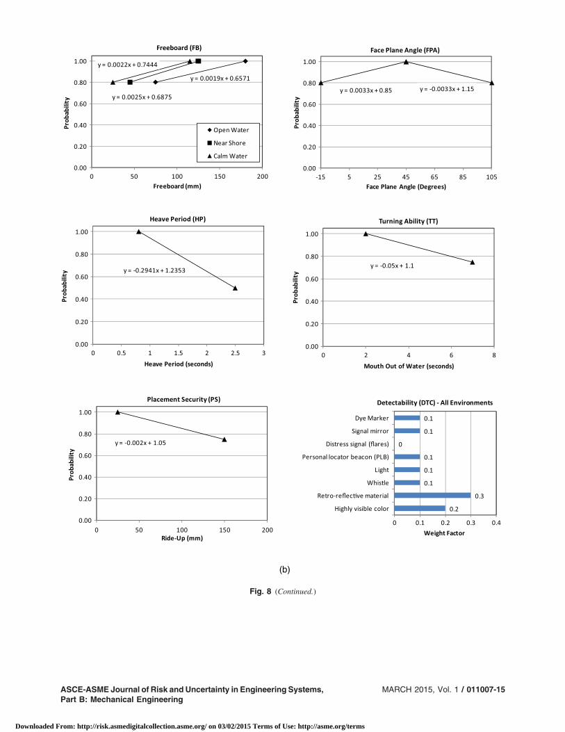
measures of freeboard, face plane angle, heave period, turningability, placement security, and detectability, i.e., 0.30FBþ0.28HPþ 0.20TTþ 0.10FPAþ 0.10PS þ 0.02DTC usingweight factors as determined from expert elicitation of0.30, 0.28, 0.20, 0.10, 0.10, and 0.02.
Table 7 defines the events related to PFD being properly donned.The basic events and parameters used in Eq. (1) are defined in sub-sequent paragraphs. The probabilities of events and parametersrelating to respective PFD tests along with suggested default valuesare provided in subsequent paragraphs.
(a)
Fig. 8 (a) Illustrative PFD performance effectiveness relationships for adults, (b) Illustrative PFD Performance effectivenessrelationships for children, and (c) Illustrative PFD performance effectiveness relationships for infants
011007-14 / Vol. 1, MARCH 2015 Transactions of the ASME
Downloaded From: http://risk.asmedigitalcollection.asme.org/ on 03/02/2015 Terms of Use: http://asme.org/terms
(b)
Fig. 8 (Continued.)
ASCE-ASME Journal of Risk and Uncertainty in Engineering Systems,Part B: Mechanical Engineering
MARCH 2015, Vol. 1 / 011007-15
Downloaded From: http://risk.asmedigitalcollection.asme.org/ on 03/02/2015 Terms of Use: http://asme.org/terms

3.3 Inflatable Devices. The performance of a PFD in this casealso depends on four primary events as shown in Fig. 4. Becauseof dependencies among these events, a probability tree of successscenarios is used as shown in Fig. 6 and Table 8. The performancesuccess probability PðSÞ of a PFD can be computed by using Eq. (1)where in this case
• PðAVÞ = probability that the PFD is available when needed.
• PðDjAVÞ = probability that the PFD is properly donnedgiven it is available, or PðD1 ∪ D2 ∪ D3 ∪ D5 ∪ D6 ∪D7 ∪ D9 ∪ D11 ∪ D12Þ.
• PðRjAV;DÞ = probability that the PFD is reliable given thatit is properly donned and available, or PðBME ∩ PMB ∩ROC ∩ SNDF ∩ SNDMBÞ.
• PðEFFjAV;D;RÞ = probability that the PFD is effectivegiven that it is available, properly donned, and reliable. This
(c)
Fig. 8 (Continued.)
011007-16 / Vol. 1, MARCH 2015 Transactions of the ASME
Downloaded From: http://risk.asmedigitalcollection.asme.org/ on 03/02/2015 Terms of Use: http://asme.org/terms

value is determined as the weighted sum of performancemeasures of freeboard, face plane angle, heave period, turn-ing ability, placement security, and detectability, e.g., inthe case of inherently buoyant PFDs, the weighted sum canbe computed as 0.30FBþ 0.28HPþ 0.20TTþ 0.10FPAþ0.10PSþ 0.02DTC using weight factors as determined fromexpert elicitation of 0.30, 0.28, 0.20, 0.10, 0.10, and 0.02.
Table 9 defines the events related to PFD being properly donned.The basic events and parameters used in Eq. (1) are defined in sub-sequent paragraphs. The probabilities of events and parameters areprovided or related to respective PFD tests in subsequent paragraphsalong with suggested default values.
3.4 Hybrid Devices. The performance of a PFD in this casealso depends on four primary events as shown in Fig. 4. Because of
dependencies among these events, a probability tree of success sce-narios is used as shown in Fig. 7 and Table 10. The performancesuccess probability PðSÞ of a PFD can be computed by using Eq. (1)where for hybrid devices, two cases of effectiveness, full and partial,are considered as follows:
• PðAVÞ = probability that the PFD is available when needed.• PðDjAVÞ = probability that the PFD is used with full buoy-
ancy (inflated) given it is available, or PðD1 ∪ D2 ∪ D3 ∪D5 ∪ D6 ∪ D7 ∪ D9 ∪ D11 ∪ D12Þ.
• PðRjAV;DÞ = probability that the PFD is reliable given thatit is donned and available, or PðBME ∩ PMB ∩ ROC ∩SNDF ∩ SNDMBÞ.
• PðEFFLjAV;D;RÞ = probability that the PFD is properlyeffective given that it is available, donned, and reliable whenPFD is used with full buoyancy (inflated). This value is de-termined as the weighted sum of performance measures of
Table 15(a) Recommended event relationships for inherently buoyant PFD designs
Event (symbol) and environmentsPrimary units
(secondary units)Comments orlimitations
Linear model defined by two points:(parameter value, probability)(corresponding secondary units)
First point Second point
Buoyant material effective (BME) N (lb) Average value (70, 0.7) (15.5, 0.7) (100, 0.95) (22.0, 0.95)Open-water (OW) environment
Buoyant material effective (BME) N (lb) Average value (50, 0.7) (11.0, 0.7) (85, 0.95) (18.5, 0.95)Near-shore (NS) environment
Buoyant material effective (BME) N (lb) Average value (35, 0.7) (7.5, 0.7) (70, 0.95) (15.5, 0.95)Calm-water (CW) environment
Don PFD before entering the water (DP) s Average value (15, 1) (60, 0.80)All environments
Don PFD after entering the water (DA) s Average value (15, 1) (60, 0.80)All environments
PFD maintains buoyancy (PMB) Not applicable Average value Probability ¼ 1, if buoyant materials meetapplicable standards; otherwise 0All environments
Shell not defective (SNDF) Not applicable Average value Probability ¼ 0.999 if PFD passes applicablestandardsAll environments
Shell not defective before entering water (SNDMB) Not applicable Average value Probability ¼ 0.999 if PFD passes applicablestandardsAll environments
Shell not damaged after entering water (SNDMA) Not applicable Average value Probability ¼ 0.999, if PFD passes applicablestandards, such as the
UL 1123 dynamic strength testAll environments
Other components vital toproviding buoyancy operate (ROC)
Not applicable Average value Probability ¼ 0.999
All environmentsWearability (W) Not applicable See Tables 15(b–c)All environments
Table 15(b) Adult wearability factors
Wearability (W) factors
Weight factorfor open-waterenvironment
Weight factorfor near-shoreenvironment
Weight factorfor calm-waterenvironment
Score in the range [0,1] inmeeting the intent of each factor Points defining model
Range of motion 0.2 0.2 0.25 Multiply the score by the weightfactor. Add up the products toobtain a weighted score toobtain W as follows:
Open-water environment:min. possible W ¼ 0.1; max.possible W ¼ 0.5
Seating comfort 0.1 0.1 0.1
Appearance and color 0.1 0.1 0.1 Open-water environment:W ¼ 0.1þ ðweighted scoreÞ0.40
Near-shore environment: min.possible W ¼ 0.1; max.possible W ¼ 0.55Perceived comfort: breathable
shell, mesh shoulders, sidepanels
0.15 0.15 0.1 Near-shore environment:W ¼ 0.1þ ðweighted scoreÞ0.45
Actual comfort: breathableshell, mesh shoulders, sidepanels
0.2 0.2 0.2 Calm-water environment:W ¼ 0.1þ ðweighted scoreÞ0.7
Calm-water environment:min. possible W ¼ 0.1; max.possible W ¼ 0.8
Amount of body coverage 0 0 0Appropriateness for activity/appropriateness for accepteduser practice
0.1 0.1 0.1
Stiffness/flexibility 0 0 0Bulkiness 0.15 0.15 0.15
Max. = maximum; Min. = minimum.
ASCE-ASME Journal of Risk and Uncertainty in Engineering Systems,Part B: Mechanical Engineering
MARCH 2015, Vol. 1 / 011007-17
Downloaded From: http://risk.asmedigitalcollection.asme.org/ on 03/02/2015 Terms of Use: http://asme.org/terms

freeboard, face plane angle, heave period, turning ability, pla-cement security, and detectability.
• PðEFFPjAV;D;RÞ = probability that the PFD is partially ef-fective given that it is available, donned, and reliable whenPFD is used with partial buoyancy (uninflated). This value isalso determined as the weighted sum of performance mea-sures of corresponding partial values of freeboard, face planeangle, heave period, turning ability, placement security, anddetectability.
Table 11 defines the events related to PFD being properlydonned. The basic events and parameters used in Eq. (1) are definedin subsequent paragraphs. The probabilities of events and parame-ters are provided or related to respective PFD tests in subsequentparagraphs along with suggested default values.
4 Effectiveness and Performance ProbabilitiesTables 12(a–d) summarize the full and partial adult PFD perfor-
mance effectiveness results and limits on PFD performance for all
buoyancy methods and environments. These tables include rejec-tion and restriction limits. The restriction limits are applicableonly to PFDs with restrictions on the use of the device, whereasthe rejection limits assign a probability of zero to the correspond-ing event or parameter, which in turn forbids certification of thedesign for these cases. For child and infant PFDs, the values inTables 13(a–d), and Tables 14(a–d), respectively, should be used.
Figure 8(a–c) shows PFD performance-effectiveness relation-ships for freeboard, heave period, turning time and ability, faceplane angle, placement security based on ride-up, and detectabilityfor the purpose of illustration, using the respective values for adults,children, and infants as examples. The values provided for childrenand infants are preliminary illustrative values, and they should beadopted with additional examination and testing.
Tables 15(a–e) summarize the PFD event probabilities andrestrictions for inherently buoyant devices and all environments.Tables 16(a–c) summarize those for inflatable and hybrid devicesand all environments. Tables 17(a–c) summarizes the PFD userprobability results for adults, children, and infants, respectively. De-fault values (DF) are provided for use in case of missing data for aPFD, beta testing, and analysis, or in cases where the parameters
Table 15(c) Example child wearability factors
Wearability (W) factorsa
Weight factorfor open-waterenvironment
Weight factorfor near shoreenvironment
Weight factorfor calm-waterenvironment
Score in the range [0,1] inmeeting the intent of each factor Points defining model
Range of motion 0.2 0.2 0.3 Multiply the score by the weightfactor. Add up the products toobtain a weighted score toobtain W as follows:
Open-water environment:min. possible W ¼ 0.1; max.possible W ¼ 0.6
Seating comfort 0.1 0.1 0.1
Appearance and color 0.2 0.2 0.2 Open-water environment:W ¼ 0.1þ ðweighted scoreÞ0.50
Perceived comfort: breathableshell, mesh shoulders, sidepanels
0.15 0.15 0.15 Near-shore environment:W ¼ 0.1þ ðweighted scoreÞ0.6
Near-shore environment: min.possible W ¼ 0.1; max.possible W ¼ 0.7
Actual comfort: breathableshell, mesh shoulders, sidepanels
0.15 0.15 0.15
Amount of body coverage 0 0 0 Calm-water environment:W ¼ 0.1þ ðweighted scoreÞ0.7
Calm-water environment:min. possible W ¼ 0.1; max.possible W ¼ 0.8
Appropriateness for activity/appropriateness for accepteduser practice
0.1 0.1 0.1
Stiffness/flexibility 0 0 0Bulkiness 0.1 0.1 0.1
Max. = maximum; Min. = minimum.aFactors with zero weight factors are retained for consistency in presentations across users (i.e., adult, child, and infant).
Table 15(d) Example infant wearability factors
Wearability (W) factors
Weight factorfor open-waterenvironment
Weight factorfor near-shoreenvironment
Weight factorfor calm-waterenvironment
Score in the range [0,1] inmeeting the intent of each factor Points defining model
Range of motion 0.15 0.15 0.15 Multiply the score by the weightfactor. Add up the products toobtain a weighted score toobtain W as follows:
Open-water environment:min. possible W ¼ 0.10:1;max. possible W ¼ 0.75
Seating comfort 0.1 0.1 0.1
Appearance and color 0.2 0.2 0.2 Open-water environment:W ¼ 0.10:1þ ðweighted scoreÞ0.65
Near-shore environment: min.possible W ¼ 0.1; max.possible W ¼ 0.75
Perceived comfort: breathableshell, mesh shoulders, sidepanels
0.2 0.2 0.2
Actual comfort: breathableshell, mesh shoulders, sidepanels
0.25 0.25 0.25 Near-shore Environment:W ¼ 0.1þ ðweighted scoreÞ0.65
Amount of body coverage 0 0 0 Calm-water environment:min. possible W ¼ 0.1; max.possible W ¼ 0.8
Appropriateness for activity/appropriateness for accepteduser practice
0 0 0 Calm-water environment:W ¼ 0.1þ ðweighted scoreÞ0.7
Stiffness/flexibility 0 0 0Bulkiness 0.1 0.1 0.1
Max. = maximum; Min. = minimum.
011007-18 / Vol. 1, MARCH 2015 Transactions of the ASME
Downloaded From: http://risk.asmedigitalcollection.asme.org/ on 03/02/2015 Terms of Use: http://asme.org/terms

Table 15(e) Recommended limitations on event relationships for inherently buoyant PFD designs
Event (symbol) (units) Open-water (OW) environment Near-shore (NS) environment Calm-water (CW) environmentExamplerestrictions
Buoyant material effective(BME) (N (lb))
Prob: ¼ 0 for BME < 70 (15.5) Prob: ¼ 0 for BME < 50 (11.5) Prob: ¼ 0 for BME < 35 (7.5) NoneProb: ¼ 1 for BME > 105 (23.3) Prob: ¼ 1 for BME > 91 (20.0) Prob: ¼ 1 for BME > 78 (17.1)DF ¼ 70 (15.5) DF ¼ 50 (11.0) DF ¼ 35 (7.5)
Don PFD before enteringthe water (DP) (s)
Prob: ¼ 1 for DP < 15 Prob: ¼ 1 for DP < 15 Prob: ¼ 1 for DP < 15 Conditionalupon
being wornProb: ¼ 0 for DP > 120 Prob: ¼ 0 for DP > 120 Prob: ¼ 0 for DP > 120DF ¼ 20 DF ¼ 20 DF ¼ 20
Don PFD after enteringthe water (DA) (s)
Prob: ¼ 0.88 for DA < 42 Prob: ¼ 0.88 for DA < 42 Prob: ¼ 0.88 for DA < 42 NoneProb: ¼ 0 for DA < 240 Prob: ¼ 0 for DA > 240 Prob: ¼ 0 for DA > 240DF ¼ 90 DF ¼ 90 DF ¼ 90
PFD maintains buoyancy(PMB)
Probability = 0, if buoyant materials does not meet applicable standard requirements NoneDF ¼ 1
Shell not defective (SNDF) DF ¼ 0.999 None
Shell not defective beforeentering water (SNDMB)
DF ¼ 0.999 None
Shell not damaged afterentering water (SNDMA)
DF ¼ 0.999, if PFD passes applicable standard requirements, such as the ISO dynamic strength test None
Other components vital toproviding buoyancy operate(ROC)
DF ¼ 0.999 None
Wearability (W) See Tables 15(b–c) None
DF = default value; Prob. = probability.
Table 16(a) Recommended event relationships for inflatable and hybrid PFD designs for all environments
Event (symbol) and environmentsTwo points:
intercept, slope LimitationsLinear model and points
defining model
Automatic activation functions (AAF) 1.075, −0.0375 Average value 2 s < x < 10 sAll environments, for both INF and HYB 2(1), 10(0.7)Gas does not exceed the burst pressure for compartment (CASA) NA Average value Probability ¼ 1, if device meet
ISO requirements; otherwise 0All environments, for both INF and HYBCylinder properly loaded (auto-inflation) (CLPA) NA NA Use default value in Table 16(b)All environments, for both INF and HYBCylinder properly loaded (manual) (CLPM) NA NA Use default value in Table 16(b)All environments, for both INF and HYBCylinder not defective (auto-inflation) (CNDA) NA NA Use default value in Table 16(b)All environments, for both INF and HYBCylinder not defective (manual) (CNDM) NA NA Use default value in Table 16(b)All environments, for both INF and HYBCylinder not previously activated (auto-inflation) (CNPAA) NA NA Use default value in Table 16(b)All environments, for both INF and HYBCylinder not previously activated (manual) (CNPAM) NA NA Use default value in Table 16(b)All environments, for both INF and HYBRelief valve functions (RVF) NA NA Use default value in Table 16(b)All environments, for both INF and HYBManual activation mechanism functions before entering the water (MAMF) 1.0667, −0.0133 Average value 5 s < x < 20 sAll environments, for INF 5(1), 20(0.8)Manual activation mechanism functions before entering the water (MAMF) 1.0333, −0.0067 Average value 5 s < x < 20 sAll environments, for HYB 5(1), 20(0.9)Manual activation mechanism functions after entering the water (MAMFA) 1.15, −0.03 Average value 5 s < x < 20 sAll environments, for INF 5(1), 15(0.7)Manual activation mechanism functions after entering the water (MAMFA) 1.3, −0.02 Average value 15 s < x < 30 sAll environments, for HYB 15(1), 30(0.7)Mouth activation functions using oral inflator (after entering the water)(MAWA)
1.1714, −0.0114 Average value 15 s < x < 50 s
All environments, for INF 15(1), 50(0.6)Mouth activation functions using oral inflator (after entering the water)(MAWA)
1.0769, −0.0031 Average value 25 s < x < 90 s
All environments, for HYB 25(1), 90(0.8)Mouth activation functions using oral inflator (before entering the water)(MAWB)
1.125, −0.0063 Average value 20 s < x < 60 s
All environments, for INF 20(1), 60(0.75)Mouth activation functions using oral inflator (before entering water)(MAWB)
1.1, −0.0033 Average value 30 s < x < 90 s
All environments, for HYB 30(1), 90(0.8)
HYB = hybrid; INF = inflatable; NA = not applicable.
ASCE-ASME Journal of Risk and Uncertainty in Engineering Systems,Part B: Mechanical Engineering
MARCH 2015, Vol. 1 / 011007-19
Downloaded From: http://risk.asmedigitalcollection.asme.org/ on 03/02/2015 Terms of Use: http://asme.org/terms

and their tests do not apply for a particular environment for the PFD.The default values cannot be used in lieu of testing, for certification,or for meeting standard requirements. The default values were se-lected through consensus by subject matter experts at special work-shops held for this purpose.
5 Minimum Aggregate PerformanceThe minimum aggregate performance of a PFD is quantified in
terms of two measures of effectiveness and success probability,where effectiveness has two parts of full and partial effectiveness,as follows:
• PðEFFLjAV;D;RÞ = probability that the PFD is properly ef-fective given that it is available, donned, and reliable whenPFD is used with full buoyancy (inflated). This value is de-termined as the weighted sum of performance measures offreeboard, face plane angle, heave period, turning ability, pla-cement security, and detectability.
• PðEFFPjAV;D;RÞ = probability that the PFD is partially ef-fective given that it is available, donned, and reliable whenPFD is used with partial buoyancy (uninflated or partiallyinflated). This value is also determined as the weightedsum of performance measures of corresponding partial va-lues of freeboard, face plane angle, heave period, turningability, placement security, and detectability.
• PðSÞ = performance success probability of a PFD can becomputed according to Eq. (1) as follows: PðSÞ ¼PðAVÞPðDjAVÞPðRjAV;DÞPðEFFjAV;D;RÞ.
The minimum aggregate full effectiveness for PðEFFLjAV;D;RÞ is 0.78, which is the probability that the PFD is effective whenavailable, donned, and reliable. The minimum aggregate partial ef-fectiveness for PðEFFPjAV;D;RÞ is 0.78, which is the probabilitythat the PFD is effective when available, donned, and reliable. Theminimum values for PðEFFLjAV;D;RÞ and PðEFFPjAV;D;RÞ arethe same; however, the underlying performance models for the twocases have different coefficients.
Table 16(b) Recommended limitations on event relationships for inflatable and hybrid PFD designs
Event (symbol) All environments (open water (OW), near shore (NS), and calm water (CW))Examplerestrictions
Automatic activation functions (AAF) Prob: ¼ 1 for AFF < 2; Prob: ¼ 0 for AFF > 10; DF ¼ 8 NoneGas does not exceed the burst pressure for compartment(CASA)
Probability ¼ 0, if device does not meet applicable standard requirements;DF ¼ 1
None
Cylinder properly loaded (auto-inflation) (CLPA) DF ¼ 0.97 with required seal indicator; DF ¼ 0.82 for devices with restrictionsand without indicator; DF ¼ 0.97 for devices with restrictions and with indicator
None
Cylinder properly loaded (manual) (CLPM) DF ¼ 0.97 with required seal indicator; DF ¼ 0.82 for devices with restrictionsand without indicator; DF ¼ 0.97 for devices with restrictions and with indicator
None
Cylinder not defective (auto-inflation) (CNDA) DF ¼ 0.9999 NoneCylinder not defective (manual) (CNDM) DF ¼ 0.9999 NoneCylinder not previously activated (auto-inflation)(CNPAA)
DF ¼ 0.97 with required seal indicator; DF ¼ 0.82 for devices with restrictionsand without indicator; DF ¼ 0.97 for devices with restrictions and with indicator
None
Cylinder not previously activated (manual) (CNPAM) DF ¼ 0.97 with required seal indicator; DF ¼ 0.82 for devices with restrictionsand without indicator; DF ¼ 0.97 for devices with restrictions and with indicator
None
Relief valve functions (RVF) DF ¼ 0.99 NoneManual activation mechanism functions before enteringthe water (MAMF), for INF
Prob: ¼ 1 for MAMF < 5; Prob: ¼ 0 for MAMF > 20; DF ¼ 15 None
Manual activation mechanism functions before enteringthe water (MAMF), for HYB
Prob: ¼ 1 for MAMF < 5; Prob: ¼ 0 for MAMF > 30; DF ¼ 15 None
HYB = hybrid; INF = inflatable; DF = default value; Prob. = probability.
Table 16(c) Recommended limitations on event relationships for inflatable and hybrid PFD designs
Event (symbol)Open-water (OW)
environment Near-shore (NS) environmentCalm-water (CW)
environmentExamplerestrictions
Manual activation mechanismfunctions after entering the water(MAMFA), for INF
Prob: ¼ 1 for MAMFA < 5;Prob: ¼ 0 for MAMFA > 20;DF ¼ 15
Prob: ¼ 1 for MAMFA < 5;Prob: ¼ 0 for MAMFA > 25;DF ¼ 15
Prob: ¼ 1 for MAMFA < 5;Prob: ¼ 0 for MAMFA > 25;DF ¼ 15
None
Manual activation mechanismfunctions after entering the water(MAMFA), for HYB
Prob: ¼ 1 for MAMFA < 15;Prob: ¼ 0 for MAMFA > 30;DF ¼ 15
Prob: ¼ 1 for MAMFA < 15;Prob: ¼ 0 for MAMFA > 30;DF ¼ 15
Prob: ¼ 1 for MAMFA < 15;Prob: ¼ 0 for MAMFA > 30;DF ¼ 15
None
Mouth activation functions usingoral inflator (after entering water)(MAWA), for INF
Prob: ¼ 1 for MAWA < 15;Prob: ¼ 0 for MAWA > 60;DF ¼ 25
Prob: ¼ 1 for MAWA < 15;Prob: ¼ 0 for MAWA > 60;DF ¼ 25
Prob: ¼ 1 for MAWA < 15;Prob: ¼ 0 for MAWA > 60;DF ¼ 25
None
Mouth activation functions usingoral inflator (after entering water)(MAWA), for HYB
Prob: ¼ 1 for MAWA < 25;Prob: ¼ 0 for MAWA > 60;DF ¼ 25
Prob: ¼ 1 for MAWA < 25;Prob: ¼ 0 for MAWA > 60;DF ¼ 25
Prob: ¼ 1 for MAWA < 25;Prob: ¼ 0 for MAWA > 75;DF ¼ 25
None
Mouth activation functions usingoral inflator (before entering water)(MAWB), for INF
Prob: ¼ 1 for MAWB < 20;Prob: ¼ 0 for MAWB > 60;DF ¼ 30
Prob: ¼ 1 for MAWB < 20;Prob: ¼ 0 for MAWB > 60;DF ¼ 30
Prob: ¼ 1 for MAWB < 20;Prob: ¼ 0 for MAWB > 60;DF ¼ 30
None
Mouth activation functions usingoral inflator (before entering water)(MAWB), for HYB
Prob: ¼ 1 for MAWB < 30;Prob: ¼ 0 for MAWB > 60;DF ¼ 30
Prob: ¼ 1 for MAWB < 30;Prob: ¼ 0 for MAWB > 60;DF ¼ 30
Prob: ¼ 1 for MAWB < 30;Prob: ¼ 0 for MAWB > 60;DF ¼ 30
None
HYB = hybrid; INF = inflatable; DF = default value; Prob. = probability.
011007-20 / Vol. 1, MARCH 2015 Transactions of the ASME
Downloaded From: http://risk.asmedigitalcollection.asme.org/ on 03/02/2015 Terms of Use: http://asme.org/terms

The minimum success probability for PFDs is 0.5200, definedcorresponding to a 0.9000 conditional success probability. Theconditional success probability is based on the parameters ofTables 17(a–c) taking their maximum possible values of 1.
6 Web Tool and ExamplesThe PFDRRAweb tool was prepared to enable the assessment of
a PFD design to save lives following marine events for the purpose
of verification of the models. It evaluated all the scenarios andresults in probabilities of aggregate performance and lifesaving.It offered a formal structure and consistency for dealing withnew concepts and special classes of PFD designs by establishinglifesaving probability equivalency to current standards and existingaccepted designs. It also aided in identifying critical factors for thePFD performance necessary to establish equivalence. The tool wasused to: (1) manage available PFDs, (2) enter data to analyze a newPFD, or (3) view sample PFDs in the database. Entering data on newPFDs was based on duplicating existing PFD records. The web tool
Table 17(b) Example event probabilities relating to PFD users for all buoyancy methods for children
Event (symbol)Open-water (OW)
environmentNear-shore (NS)environment
Calm-water (CW)environment
PFD available (AV) 1 1 1Person conscious after entering water (CA) 0.95 0.98 0.98Person conscious | out of water (CP) 0.99 0.99 0.99Environment does not impair donning in water (EDI) 0.5 0.7 0.7Environment does not impair swimming (ENV) 0.6 0.725 0.8Skill/knowledge to swim (KS) 0.7 0.8 0.8Marine event (ME) 1 1 1Person not fatigued | in water (NFI) 0.6 0.8 0.8Person not fatigued | out of water (NFO) 0.9 0.9 0.9Person not handicapped out of water (NH) 0.9 0.95 0.95Person not handicapped in water (NHI) 0.87 0.9 0.9Person not injured | in water (NII) 0.9 0.9 0.9Person not intoxicated | in water (NINTI) 1 1Person not intoxicated | out of water (NINTO) 1 1 1Person not injured | out of water (NIO) 0.99 0.99 0.99
Table 17(c) Example event probabilities relating to PFD users for all buoyancy methods for infants
Event (symbol)Open-water (OW)
environmentNear-shore (NS)environment
Calm-water (CW)environment
PFD available (AV) 1 1 1Person conscious after entering water (CA) 0.95 0.98 0.98Person conscious | out of water (CP) 0.99 0.99 0.99Environment does not impair donning in water (EDI) 0.5 0.7 0.7Environment does not impair swimming (ENV) 0.6 0.7 0.6Skill/knowledge to swim (KS) 0 0 0Marine event (ME) 1 1 1Person not fatigued | in water (NFI) 0.6 0.8 0.8Person not fatigued | out of water (NFO) 0.9 0.9 0.9Person not handicapped out of water (NH) 0.9 0.95 0.95Person not handicapped in water (NHI) 0.87 0.9 0.9Person not injured | in water (NII) 0.9 0.9 0.9Person not intoxicated | in water (NINTI) 1 1 1Person not intoxicated | out of water (NINTO) 1 1 1Person not injured | out of water (NIO) 0.99 0.99 0.99
Table 17(a) Recommended event probabilities relating to PFD users for all buoyancy methods for adults
Event (symbol)Open-water (OW)
environmentNear-shore (NS)environment
Calm-water (CW)environment
PFD available (AV) 1 1 1Person conscious after entering water (CA) 0.95 0.98 0.98Person conscious | out of water (CP) 0.99 0.99 0.99Environment does not impair donning in water (EDI) 0.5 0.7 0.7Environment does not impair swimming (ENV) 0.6 0.775 0.8Skill/knowledge to swim (KS) 0.7 0.85 0.85Marine event (ME) 1 1 1Person not fatigued | in water (NFI) 0.6 0.8 0.8Person not fatigued | out of water (NFO) 0.9 0.9 0.9Person not handicapped out of water (NH) 0.9 0.95 0.95Person not handicapped in water (NHI) 0.87 0.9 0.9Person not injured | in water (NII) 0.9 0.9 0.9Person not intoxicated | in water (NINTI) 0.85 0.85 0.85Person not intoxicated | out of water (NINTO) 0.85 0.85 0.85Person not injured | out of water (NIO) 0.99 0.99 0.99
ASCE-ASME Journal of Risk and Uncertainty in Engineering Systems,Part B: Mechanical Engineering
MARCH 2015, Vol. 1 / 011007-21
Downloaded From: http://risk.asmedigitalcollection.asme.org/ on 03/02/2015 Terms of Use: http://asme.org/terms

included many example cases. The tool was very helpful in devel-oping the model; however it is not available to the public at presentand not supported.
AcknowledgmentThe authors would like to acknowledge the financial support un-
der grants from the Sport Fish Recreational and Boating Trust Fundadministered by the USCG and the PFD manufacturing industry,and the input from industry representatives throughout the develop-ment process. The assistance and valuable efforts of Dr. RobbWilcox, Khalid Nejim, Bob Askew, Clara Popescu, Dr. WilliamMcGill, Dr. Sid Lahiri, and Phil Cappel are greatly appreciated.The facilitation and input from the Underwriter Laboratories andPFD Manufacturer Association are greatly appreciated.
Appendix
Heave Period TestingThe dynamic performance characteristics of a PFD are some
of the attributes that affect the airway protection provided by thedevice, particularly when used in waves. In general, mouth immer-sions are more likely to occur when wearing a device with a longernatural heave period if all other characteristics are equal. Flotationattitude affects dynamic performance and the ability to effectivelymeasure heave period. The natural heave period of the PFD system(the PFD and wearer combined) is to be evaluated by exciting thesystem vertically. Because the characteristics of the wearer influ-ence the heave period of the PFD system, the heave period resultsare to be taken with a subject with specific size and flotation char-acteristics. Data shall be collected by videotaping the wearer in frontof a grid (with a 25 mm (1 in.) or smaller horizontal line spacing.)To reduce the interference of waves, the test is to be conducted in atest tank that incorporates a gutter around the entire perimeter andthat is filled to the top of the gutter (þ7, −0 mm) or an equivalentarrangement. To represent someone that generally floats in a morevertical attitude, a male test subject who meets the following criteriashall be used:
Height ¼ 1800þ = − 10 mm (71þ = − 1 in:)Mass = 70–90 kg (160–200 lb)In-water weight = 50–55 N (11–12 lb)Torso flotation angle in reference vest ¼ 35þ = − 7 degreesShoulder height = to be measured and recordedWaist height = to be measured and recordedChest size = to be measured and recordedWaist girth = to be measured and recordedNeck circumference = to be measured and recordedHead circumference = to be measured and recordedThe test subject’s height, dry mass, chest size, in-water weight,
and flotation angle in the reference vest shall be measured to ensurethat they comply with the above criteria. The additional anthropo-morphic measurements above shall be recorded. Instruction andtraining shall be given to the subject, e.g., test procedures, relaxationor position-holding techniques, and breath holding.
The PFD is to be donned by the test subject in its intendedmanner and adjusted by the test engineer to a snug fit, and thenthe subject enters the water. Hybrid and inflatable PFDs shall betested fully inflated. The test subject shall complete three bobs perthe ride-up test procedure to ensure the PFD is properly secured andsettled into the expected position on the wearer when being worn inwaves and/or after swimming or assisting in abandonment. The testsubject shall then to relax into a natural attitude of static balance.The face plane, torso, and body list angles shall be measured andrecorded.
The subject shall be placed in front of a vertical grid with thezero grid line at the water level located at least 1000 mm (3 ft) fromthe gutter edge of the pool as shown in Fig. 9. The starting positionof the subject shall be as close as possible to the grid. The subject
shall not contact the grid during the test. The camera shall be posi-tioned such that the center of the lens is at a height of 250 mm(þ= − 25 mm) (10þ = − 1 in:.) from the waterline, perpendicularto the grid, and at least 2.5 m from the subject to allow reading thedisplacement range of the subject’s head after being excited with avertical push.
The subject shall relax for at least 15 s and breathe normallywhile the face plane, torso, and body list angles are measured andrecorded before any excitations. The subject shall hold a half breath(top of the tidal volume) while the test is conducted with the fol-lowing posture: starting from a relaxed flotation attitude, stiffenthe neck, bring the hands to the sides and feet together, and holdthe stiffened arms and legs in that position. The subject shall beinstructed that the stiffened positions are not to be excessively tenseor rigid, but that the head or limbs should not be allowed to relax ormove freely relative to the torso.
The method of initial excitation of the wearer/PFD system shallbe in the vertical direction in a manner that minimizes splashing andpitching (body angle change) or movement in other than the verticaldirection to the extent possible; the same torso angle needs to bemaintained. The recommended method for excitation is to momen-tarily push downward and immediately release the subject. If thereis excessive pitching induced, the procedure should be repeated bypushing down at another location closer to the center of buoyancy orif necessary by pushing at two locations to displace the subject witha minimum of change in body angle. The excitation should be suf-ficient to provide at least three complete heave oscillations after thewearer is released, or if the system damping does not permit threecomplete oscillations, multiple runs/tests shall be taken to provide atleast three complete cycles.
This method requires a video processing software package thatcan import raw digital video and compress the video into frames.There are two standard frame rates, NTSC and PAL, which shoot at30=1.001 (about 29.97) frames per second and 25 frames per sec-ond, respectively. Assigning a frame rate to the raw video allowsone to establish time stamps to the hundredths of a second. Themaximum height of movement of the head in the vertical directionshall be recorded after initial excitation. The corresponding frametime (FT1) shall also be recorded. The subject will then descend intothe water. The lowest point may be recorded for half-cycle rates.The maximum height of movement of the head in the vertical di-rection shall be recorded for the next ascending cycle, along with itsframe time (FT2). The heave period shall be calculated as follows:
Fig. 9 Heave period test
011007-22 / Vol. 1, MARCH 2015 Transactions of the ASME
Downloaded From: http://risk.asmedigitalcollection.asme.org/ on 03/02/2015 Terms of Use: http://asme.org/terms

heave period ðsecondsÞ ¼ FT2 − FT1. Half cycles can be observedand doubled.
The repeatability of the system used shall be checked by runningthe test three times, and the results shall be within 15% in order forthe system to qualify to such testing.
References[1] U.S. Coast Guard, 2011, “Recreational Boating Statistics.” COMDTPUB
P16754.25, Office of Auxiliary and Boating Safety, Washington DC, http://www.uscgboating.org/statistics/accident_statistics.aspx.
[2] Underwriters Laboratories, Inc., 1996, “Standard for Safety: Marine BuoyantDevices.” UL 1123, Durham, NC.
[3] Underwriters Laboratories, Inc., 1995, “Standard for Safety: Fully InflatableRecreational Personal Flotation Devices.” UL 1180, Durham, NC.
[4] Underwriters Laboratories, Inc., 1996, “Standard for Safety for Hybrid PersonalFlotation Devices.” UL 1517, Durham, NC.
[5] Wilcox, R. C., 2001, “Risk-Based Compliance for Engineering Systems withPersonal Flotation Devices as a Case Study.” Ph.D. thesis, University ofMaryland, College Park, MD.
[6] Ayyub, B. M., and Wilcox, R. C., 2001, “Development of a Risk-based Compli-ance Approval Process for Personal Flotation Devices Using PerformanceModels.” BMA Engineering, Inc. Report to the USCG, Office of Auxiliaryand Boating Safety, Washington, DC.
[7] Wilcox, R., and Ayyub, B. M., 2002, “A Risk-Based Compliance Approval Pro-cess for Engineering Systems with Personal Floatation Devices as a Case Study,”
SNAME Transactions, Jan. 1, Society of Naval Architects and Marine Engineers,Alexandria, VA.
[8] Ayyub, B. M., and Nejaim, K., 2003 “Risk-Based Compliance Assessment Modelsfor Personal Flotation Devices,” Proceedings of the International Symposium onUncertainty Modeling and Analysis (ISUMA), N. Attoh-Okine and B. Ayyub,eds., College Park, MD, IEEE-CS, Washington, DC, pp. 241–246.
[9] BMA Engineering, Inc., 2002. “Risk-Based Compliance Approval of PersonalFlotation Devices: Beta Testing, Calibration, and Data Collection,”USCG Report,Washington, DC.
[10] Ayyub, B. M., 2014. Risk Analysis in Engineering and Economics, 2nd ed.,Chapman/Hall, CRC Press, Boca Raton, FL.
[11] Ayyub, B. M., 2001, Elicitation of Expert Opinions for Uncertainty and Risks,CRC Press, Boca Raton, FL.
[12] BMA Engineering, Inc., 2007, “Reclassification and Risk-Based Compliance:Expert Opinion Elicitation of Performance of Personal Flotation Devices,”BMA Engineering, Inc., Report to the USCG, Office of Auxiliary and BoatingSafety, Washington, DC.
[13] BMA Engineering, Inc., 2008, “Reclassification and Risk-Based Compliance:Expert Opinion Elicitation for PFD Performance and Reclassification Held onFebruary 20 and 21,” BMA Engineering, Inc., Report to the USCG, Office ofAuxiliary and Boating Safety, Washington, DC.
[14] BMA Engineering, Inc., 2010, “Reclassification and Risk-Based Compliance:Expert Opinion Elicitation for PFD Performance and Reclassification,” BMA En-gineering, Inc., Report to the USCG, Office of Auxiliary and Boating Safety,Washington, DC.
[15] Brooks, C. J., 1995, Designed for Life: Lifejackets Through the Ages, MustangEngineered Technical Apparel Corporation, Richmond, BC, Canada.
ASCE-ASME Journal of Risk and Uncertainty in Engineering Systems,Part B: Mechanical Engineering
MARCH 2015, Vol. 1 / 011007-23
Downloaded From: http://risk.asmedigitalcollection.asme.org/ on 03/02/2015 Terms of Use: http://asme.org/terms