risk register of a urea reactor: learn why– instead …...risk register of a urea reactor: learn...
TRANSCRIPT
Risk Register of a Urea Reactor: Learn Why… instead of only What…
Urea Reactors form the center of any urea plant. High pressures and temperatures, the corrosive cir-cumstances and the health risks of ammonia put high demands to the integrity of such a vessel. The UreaKnowHow.com Incident Database introduced includes already 21 serious incidents with Urea
Reactors and other similar High Pressure Equipment items.
This paper includes the Risk Register of a Urea Reactor with a 316L Urea Grade liner, typical for most urea reactors in operation. The Risk Register is a collection of possible hazards that can occur in such a urea reactor and includes the related mitigation measures: 37 safety hazards are identified and 37 recommendations / barriers are defined. These lists form a perfect learning tool about why
certain operating and maintenance procedures are done as they are done. A fact that proves to be un-expectedly enlightening is that one can conclude from the Risk Register that 65% of the identified
hazards can be potentially mitigated by operating a proper leak detection system. This paper will also define the requirements of such a leak detection system.
Dan Cojocaru
Tech Safety Group
Jo Eijkenboom UreaKnowHow.com
Mark Brouwer UreaKnowHow.com
Introduction rea Reactors form the center of any urea plant. High pressures and tem-peratures, the corrosive circumstanc-es and the health risks of ammonia in
case of a leak put high demands to the integri-ty of such a vessel. In 2014 the UreaK-nowHow.com Incident Database was intro-duced, that includes already more than seventy incidents of which
twenty-one serious incidents with Urea Reac-tors and other similar High Pressure Equip-ment items. Serious means, in this case, that the integrity of the carbon steel pressure bear-ing wall was damaged or was at risk. Find be-low an overview of the list including a short description of the causes and consequences:
1. Incident 17-001 Urea Separator dam-age after seventeen years in operation Cause: Severe corrosion and erosion of ti-tanium level pipe Consequences: Major leak, plant shut down, no injuries
U
3032017 AMMONIA TECHNICAL MANUAL

2. Incident 13-002 Urea Reactor damage after thirty-five years in operation Cause: Active corrosion during blocking in Consequences: Plant shut down, repair, no casualties, no damage to other plant parts
3. Incident 10-005 Urea Reactor rupture
after 10 years in operation Cause: Stress corrosion cracking of out-side of carbon steel wall at boiler feed wa-ter cooling jacket Consequences: Plant shut down, no casu-alties, significant damage to other plant parts
4. Incident 05-001 Urea Reactor rupture after five years in operation Cause: Stress corrosion cracking of car-bon steel behind the liner Consequences: 4 casualties, 32 injured, 4.3 MM US$ financial loss
5. Incident 04-001 Urea Reactor rupture after 14 years in operation Cause: Corrosion of carbon steel from be-hind the liner Consequences: no casualties, complete damage of the 200 mtpd total recycle urea plant
6. Incident 03-002 Urea Reactor damage Cause: Unknown Consequence: Shut down, no casualties
7. Incident 01-001 Urea Reactor rupture after maintenance shut down Cause: bad workmanship during mainte-nance Consequence: One person severely hurt due to ammonia
8. Incident 00-002 HP scrubber rupture Cause: Several explosions due to hydro-gen and oxygen
Consequence: Repair and de-hydrogenation reactor installed
9. Incident 98-003 HP Scrubber rupture
after 16 years in operation Cause: Leak detection hole was still plugged with transportation plug Consequences: Plant shut down for two months, no casualties, and significant damage to other plant parts
10. Incident 95-001 Urea Reactor rupture Cause and consequences not known
11. Incident 94-001 HP stripper leak Cause: Carbamate dripping on carbon steel wall Consequences: Plant shut down, repair, no casualties, no damage to other plant parts.
12. Incident 92-001 Urea Reactor rupture Cause: clip weld failure in liner, no active leak detection system, no proper actions after leak Consequences: 10 people injured + 90 cit-izens injured
13. Incident 91-001 HP stripper rupture Cause: bad workmanship during fabrica-tion Consequences: 12 casualties and 71 MM US$ financial loss
14. Incident 90-001 Urea Reactor rupture Cause: liner leak, no active leak detection system Consequences: Plant shut down
15. Incident 79-001 Urea Reactor leak af-ter 8 years in operation Cause: wrong design nozzle liner Consequences: repair, no casualties, no damage to other plant parts
16. Incident 78-001 Urea Reactor leak af-ter 9 years in operation
304 2017AMMONIA TECHNICAL MANUAL

Cause: corrosion of overlay welding Consequences: repair, no casualties, likely damage to other plant parts
17. Incident 77-001 Urea Reactor rupture after 14 years in operation Cause: lead liner damage, corrosion from outside Consequences: no casualties, likely dam-age to other plant parts
18. Incident 64-001 Urea Reactor rupture Cause Nitrate stress corrosion cracking from cooling jacket Consequences: no casualties, likely dam-age to other plant parts
19. Incident 59-001 Urea Reactor rupture Cause: Nitrate stress corrosion cracking from cooling water cooling coil Consequences: 5 casualties and several in-jured
20. Incident XX-004 Urea Reactor rupture Cause: Nitrate stress corrosion cracking of outside carbon steel wall Consequences: Repair, no casualties
21. Incident XX-003 Urea Reactor dam-age Cause: Nitrate stress corrosion cracking of outside carbon steel wall Consequences: Repair, no casualties
The first two numbers of the incident code in-dicate the year the incident occurred, while the next three numbers are a sequence num-ber. In case no year is known the first two numbers are replaced by XX.
Totally 21 serious incidents are found in which the carbon steel pressure bearing wall is either damaged or ruptured. During the last 25 years about every three years a serious in-cident happens in the about 500 urea plants worldwide. In 13 of the 21 (60%) incidents
the carbon steel wall ruptures and in five of these 13 (35%) incidents casualties were in-volved. These 21 incidents have led to 21 cas-ualties, >55 people injured in the plants plus 90 people injured outside the plant. In nine of the 21 (40%) incidents a failing leak detection system was one of the causes. In two cases stress corrosion cracking of the carbon steel behind the liner was found. In three of the 19 incidents Corrosion Under Insulation was one of the causes.
These 21 serious incidents are only the tip of the iceberg and numerous more near misses and minor corrosion cases form the basis. However, one should realise that urea plants differ in a distinct way from other process plants. In a urea plant corrosion cannot be avoided due to the harsh process conditions. The typical lifetime of the protection layer of a Urea Reactor is limited to some 20-30 years. As urea plants typically operate between 40-50 years, every urea plant will face end of lifetime conditions of the protective layer and thus every urea plant will at least experience a higher risk of a potential incident during this period.
What are the causes of these 21 serious inci-dents and how to avoid them? Tech Safety Group and UreaKnowHow.com prepared a Risk Register of a Urea Reactor with a 316L Urea Grade liner. This design is typical for most urea reactors currently in operation. The Risk Register is a collection of possible risks that can occur in such a urea reactor and in-cludes the related mitigation measures.
Principal design of a Urea Reactor A Urea Reactor provides the time needed to approach equilibrium of the urea formation reaction. This reaction requires some heat, which is typically supplied by the condensa-
3052017 AMMONIA TECHNICAL MANUAL

tion ammonia and carbon dioxide gases form-ing carbamate. A Urea Reactor typically is a vertical vessel with a number of horizontal trays. The gas and liquid inlet are at the bot-tom and the outlet typically is at the top or via a down-comer more to the bottom side of the reactor. The pressure bearing wall is carbon steel, which is typically a solid wall or a mul-ti-layer. All carbon steel parts in contact with ammonium carbamate are protected by a cor-rosion resistant liner or overlay welding.
Risk Register of a Urea Reactor2) The Risk Register lists all known possible hazards / risks associated with a Urea Reactor with a 316L Urea Grade protective layer and the leak detection system for the loose liner parts are only tubes outside the insulation as indicated in the picture below.
Figure 1: Typical leak detection system In such a situation a leak through the liner can only be detected visually when an operator is present close to the urea reactor at the right elevation floor. The risks in the Risk Register are identified for every phase of the life of a reactor: design, fabrication, transportation, installation, com-missioning, operation, shut down, start-up, and maintenance. The Risk Register shows for each risk: the initiating event, consequences,
prevention measure(s) and the possible miti-gation steps (barriers).
Find below the identified hazards (as per Feb-ruary 2017) of a Urea Reactor with a 316L Urea Grade alloy protection:
1. Bad workmanship, e.g. wrong design details, bad welding, wrong materials leading to defects in the protective layer.
2. Chloride contamination behind the liner leading to locally chloride stress corrosion cracking of the protective layer during operation. Chlorides can enter due to ingress of marine atmos-phere during transportation.
3. Too high pressure in the reactor caused by several possible process up-set conditions.
4. Loss of oxygen or too little oxygen for proper passivation leading to active corrosion with higher corrosion rates and possible defects in the protective layer.
5. Chloride contamination on process side leading to locally defects in pas-sive chromium-oxide layer and accel-erated rates of strain induced stress corrosion cracking.
6. Sulphur contamination on process side leading to locally defects in passive chromium-oxide layer and accelerated rates of strain induced stress corrosion cracking.
7. Too high pressure in the reactor caused by several possible process up-set conditions plus a malfunctioning pressure safety valve (for example clogged outlet line).
8. Weld defect (e.g. weld decay, knife line attack) in fixed weld connection to carbon steel wall.
306 2017AMMONIA TECHNICAL MANUAL

9. Corrosion (e.g. weld decay, knife line attack) in Heat Affected Zone (HAZ) of fixed weld connection to carbon steel wall.
10. Pinhole in tray or pipe support clip weld to liner.
11. Condensation corrosion in gas phase part of reactor due to heat sinks like lifting lugs, bad condition of tracing and insulation, supports of ladders or platforms.
12. Higher corrosion rates in areas with high velocities in gaps (e.g. between trays and protective layer) leading to defects in protective layer (erosion corrosion).
13. Clogged area behind the liner due to, for example, an earlier leak without a proper leak detection system in opera-tion.
14. Clogged leak detection hole due to, for example, earlier leak without a proper leak detection system in opera-tion.
15. Liner failure at nozzles of pipes or manway.
16. Passive corrosion of the overlay weld-ing leading to sub-surface defects.
17. Defect (e.g. pinhole, under-bead cracking, lack of fusion, two times heat input) in overlay welding.
18. Flange leakage leading to crevice cor-rosion at flange connection leading to damage of protective layer and/or car-bon steel parts of flange connection.
19. Defect in level measurement pipe. 20. Ammonium carbamate in contact with
carbon steel can lead to bi-(carbonate) stress corrosion cracking when water is present.
21. Ammonium carbamate in contact with carbon steel may lead to hydrogen in-duced stress corrosion cracking in car-bon steel in case of an oxygen free en-vironment.
22. Ammonium carbamate in contact with carbon steel pressure bearing wall (outside) leading to bi-(carbonate) stress corrosion cracking in high strength carbon steels due to leaking ammonium carbamate liquid dripping on reactor vessel.
23. Nitrate stress corrosion cracking to ex-terior side of carbon steel wall due to e.g. bad support design and/or insula-tion leading to water ingress. Note: ni-trates can originate from local nitric acid or ammonium nitrate plant or even urea conversion by bacteria.
24. Sulphur corrosion to exterior side of carbon steel wall due to e.g. bad sup-port design and/or insulation leading to water ingress.
25. Leak detection hole are closed due to crystallisation of urea, iron-oxides or any other material.
26. Buckling and damage of liner caused by too high pressure behind the liner from a pressurised leak detection sys-tem.
27. Buckling of liner due to creating a vacuum in the reactor by condensing steam during, for example, temporary holding the heating up procedure of reactor.
28. Buckling of liner due to creating a vacuum in the reactor during draining.
29. Leak detection hole still closed during operation. Note: When the reactor ar-rives at site these holes are closed to avoid ingress of chlorides and fouling during transportation.
3072017 AMMONIA TECHNICAL MANUAL
30. Strain induced stress corrosion crack-ing of 316L UG liner in area liquid - gas interface.
31. Many stops & starts and quick cooling down and heating up leads to more stresses in liner or higher risks for cracks in liner.
32. Bad workmanship during repair, e.g. bad or too much welding, wrong mate-rials leading to defects in the protec-tive layer. Note: welding gives heat input which can reduce the corrosion resistance of the protective layer.
33. Use of chloride containing marker on the protective layer leading to chloride stress corrosion cracking.
34. Blocking in too long leading to active corrosion with higher corrosion rates.
35. Higher temperatures during blocking in due to leaking in carbon dioxide leading to risks of active corrosion with higher corrosion rates.
36. Loss of oxygen in liquid in reactor during blocking in due a stripping ef-fect of some gas from the CO2 strip-per leading to risks of active corrosion with higher corrosion rates.
37. Active corrosion due to too quick blocking in again after an earlier blocking in period (no refreshment of liquid with sufficient oxygen content).
Furthermore the Risk Register shows for each identified risk a risk ranking before and after any mitigation step. The risk ranking is ap-plied for four different aspects: safety, envi-ronment, financial and reputation.
28 of the 37 identified hazards have an Intol-erable high safety risk level and 32 have an Intolerable high financial risk level. This is no surprise as these hazards endanger the me-chanical integrity of the carbon steel pressure
bearing wall leading to potential casualties and a long unplanned shut down.
The current Risk Register includes a total of 37 re-commendations or barriers to mitigate the hazards and consequences identified. Find below the list of recommendations / barriers categorised per lifetime phase of a urea reac-tor.
Design & Construction phase
Install an active leak detection system with a reliable and accurate ammonia detector, which is in operation since the first start up, mini-mizing the time that ammonium carbamate is in contact with carbon steel and minimizing the risk of clogging of the leak detection tubes. Active means an inert purge or vacuum pressure to lead any leaking fluid to the am-monia detector. Only a vacuum system ensures a direct moni-toring of the maximum liner area also in case some parts are clogged. Make use of skillful and experienced design-ers and fabricators; perform expediting ser-vices by skillful and experienced people. Note that regulatory inspectors only inspect pres-sure bearing parts. Avoid any contamination behind the liner and in the leak detection tubes by closing all leak detection holes with temporary plugs before sandblasting and, of course, during transporta-tion. Minimize the gap between the liner and the carbon steel wall. Assure full penetration and complete inspect ability of the welds of clips. Assure and maintain proper tracing and insu-lation of gas phase parts of the reactor (pro-cess temperature should remain above con-densation temperature of carbamate vapours); Remove lifting lugs; Avoid heat sinks.
308 2017AMMONIA TECHNICAL MANUAL

Avoid too small gaps between trays and pro-tective layer. Apply proper installation procedures for flange connections. Apply tracing and insulation to leak detections tubing or install these below the insulation. Properly mark leak detection holes during fab-rication of vessel. Note there can be various type of holes in high pressure equipment. Do not apply a water cooling jacket or coil on a urea reactor.
Commissioning & Operational phase
Add air during heating up procedure with steam and add pressure measurement with a vacuum pressure range. Assure continuous oxygen supply. Take daily Nickel analysis in final product and keep track of colour of final product. Avoid any chloride contamination on the pro-cess side. Minimize any sulphur contamination on the process side, try to compensate with extra ox-ygen for passivation. Shut down the plant in case of a flange leak-age. Keep leaking flange connection free of solids in order that leak can be assessed and less risks can occur of corrosion of carbon and stainless steel parts of the flange connection. Never flush behind the liner with steam or condensate. Avoid that leaking ammonium carbamate can drip on high pressure urea equipment. Assure proper connection and installation of the leak detection system. Minimize stops & starts and quick cooling down & heating up procedures. Limit blocking-in events and duration as rec-ommended by licensor.
Check temperatures in reactor during blocking in. With repeating blocking in periods, limit total blocking in period as recommended by the li-censor unless content of reactor has been re-freshed sufficiently.
Maintenance Phase
Perform corrosion inspections during turna-rounds by qualified and experienced inspec-tors with a frequency depending on on-stream time of reactor and previous inspection find-ings. Measure the wall thickness of liner and over-lay weld at same location always in order to obtain reliable corrosion rates. Make use of qualified and experienced fabri-cators and welders for repair jobs. Minimize welding as a repair procedure. If welding is required, then make use of 25-22-2 welding material during repairs. Inspect liner welds. Inspect Heat Affected Zones. Inspect liner welds and liner attachment welds (clips). Measure liner thickness at heat sinks. Inspect for cracks at liquid - gas interface. Inspect gaps and in area between tray and pro-tective layer. Inspect overlay welding. Inspect damaged insulation areas. Assure and maintain proper insulation; consider the in-stallation of a shelter on top of the reactor. Analyse insulation material for nitrates, chlo-rides and sulphates to assess environmental conditions. Remove the old liner when a relining job is due, so one is able to assess the integrity of the carbon steel pressure bearing wall. Re-place the liner with a 25-22-2 liner.
3092017 AMMONIA TECHNICAL MANUAL
And never use chloride containing markers.
Bow-Tie diagram
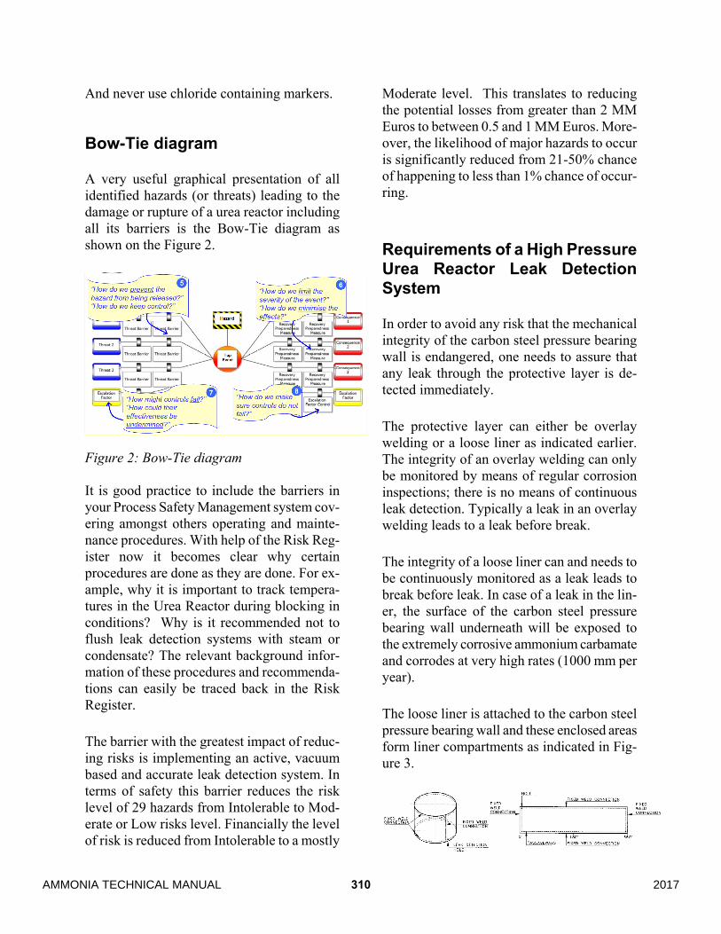
A very useful graphical presentation of all identified hazards (or threats) leading to the damage or rupture of a urea reactor including all its barriers is the Bow-Tie diagram as shown on the Figure 2.
Figure 2: Bow-Tie diagram It is good practice to include the barriers in your Process Safety Management system cov-ering amongst others operating and mainte-nance procedures. With help of the Risk Reg-ister now it becomes clear why certain procedures are done as they are done. For ex-ample, why it is important to track tempera-tures in the Urea Reactor during blocking in conditions? Why is it recommended not to flush leak detection systems with steam or condensate? The relevant background infor-mation of these procedures and recommenda-tions can easily be traced back in the Risk Register.
The barrier with the greatest impact of reduc-ing risks is implementing an active, vacuum based and accurate leak detection system. In terms of safety this barrier reduces the risk level of 29 hazards from Intolerable to Mod-erate or Low risks level. Financially the level of risk is reduced from Intolerable to a mostly
Moderate level. This translates to reducing the potential losses from greater than 2 MM Euros to between 0.5 and 1 MM Euros. More-over, the likelihood of major hazards to occur is significantly reduced from 21-50% chance of happening to less than 1% chance of occur-ring.
Requirements of a High Pressure Urea Reactor Leak Detection System
In order to avoid any risk that the mechanical integrity of the carbon steel pressure bearing wall is endangered, one needs to assure that any leak through the protective layer is de-tected immediately.
The protective layer can either be overlay welding or a loose liner as indicated earlier. The integrity of an overlay welding can only be monitored by means of regular corrosion inspections; there is no means of continuous leak detection. Typically a leak in an overlay welding leads to a leak before break.
The integrity of a loose liner can and needs to be continuously monitored as a leak leads to break before leak. In case of a leak in the lin-er, the surface of the carbon steel pressure bearing wall underneath will be exposed to the extremely corrosive ammonium carbamate and corrodes at very high rates (1000 mm per year).
The loose liner is attached to the carbon steel pressure bearing wall and these enclosed areas form liner compartments as indicated in Fig-ure 3.
310 2017AMMONIA TECHNICAL MANUAL
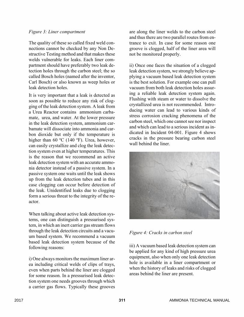
Figure 3: Liner compartment The quality of these so called fixed weld con-nections cannot be checked by any Non De-structive Testing method and that makes these welds vulnerable for leaks. Each liner com-partment should have preferably two leak de-tection holes through the carbon steel; the so called Bosch holes (named after the inventor, Carl Bosch) or also known as weep holes or leak detection holes. It is very important that a leak is detected as soon as possible to reduce any risk of clog-ging of the leak detection system. A leak from a Urea Reactor contains ammonium carba-mate, urea, and water. At the lower pressure in the leak detection system, ammonium car-bamate will dissociate into ammonia and car-bon dioxide but only if the temperature is higher than 60 oC (140 oF). Urea, however, can easily crystallize and clog the leak detec-tion system even at higher temperatures. This is the reason that we recommend an active leak detection system with an accurate ammo-nia detector instead of a passive system. In a passive system one waits until the leak shows up from the leak detection tubes and in this case clogging can occur before detection of the leak. Unidentified leaks due to clogging form a serious threat to the integrity of the re-actor.
When talking about active leak detection sys-tems, one can distinguish a pressurised sys-tem, in which an inert carrier gas stream flows through the leak detection circuits and a vacu-um based system. We recommend a vacuum based leak detection system because of the following reasons: i) One always monitors the maximum liner ar-ea including critical welds of clips of trays, even when parts behind the liner are clogged for some reason. In a pressurised leak detec-tion system one needs grooves through which a carrier gas flows. Typically these grooves
are along the liner welds to the carbon steel and thus there are two parallel routes from en-trance to exit. In case for some reason one groove is clogged, half of the liner area will not be monitored properly. ii) Once one faces the situation of a clogged leak detection system, we strongly believe ap-plying a vacuum based leak detection system is the best solution. For example one can pull vacuum from both leak detection holes assur-ing a reliable leak detection system again. Flushing with steam or water to dissolve the crystallized urea is not recommended. Intro-ducing water can lead to various kinds of stress corrosion cracking phenomena of the carbon steel, which one cannot see nor inspect and which can lead to a serious incident as in-dicated in Incident 04-001. Figure 4 shows cracks in the pressure bearing carbon steel wall behind the liner.
Figure 4: Cracks in carbon steel iii) A vacuum based leak detection system can be applied for any kind of high pressure urea equipment, also when only one leak detection hole is available in a liner compartment or when the history of leaks and risks of clogged areas behind the liner are present.
3112017 AMMONIA TECHNICAL MANUAL
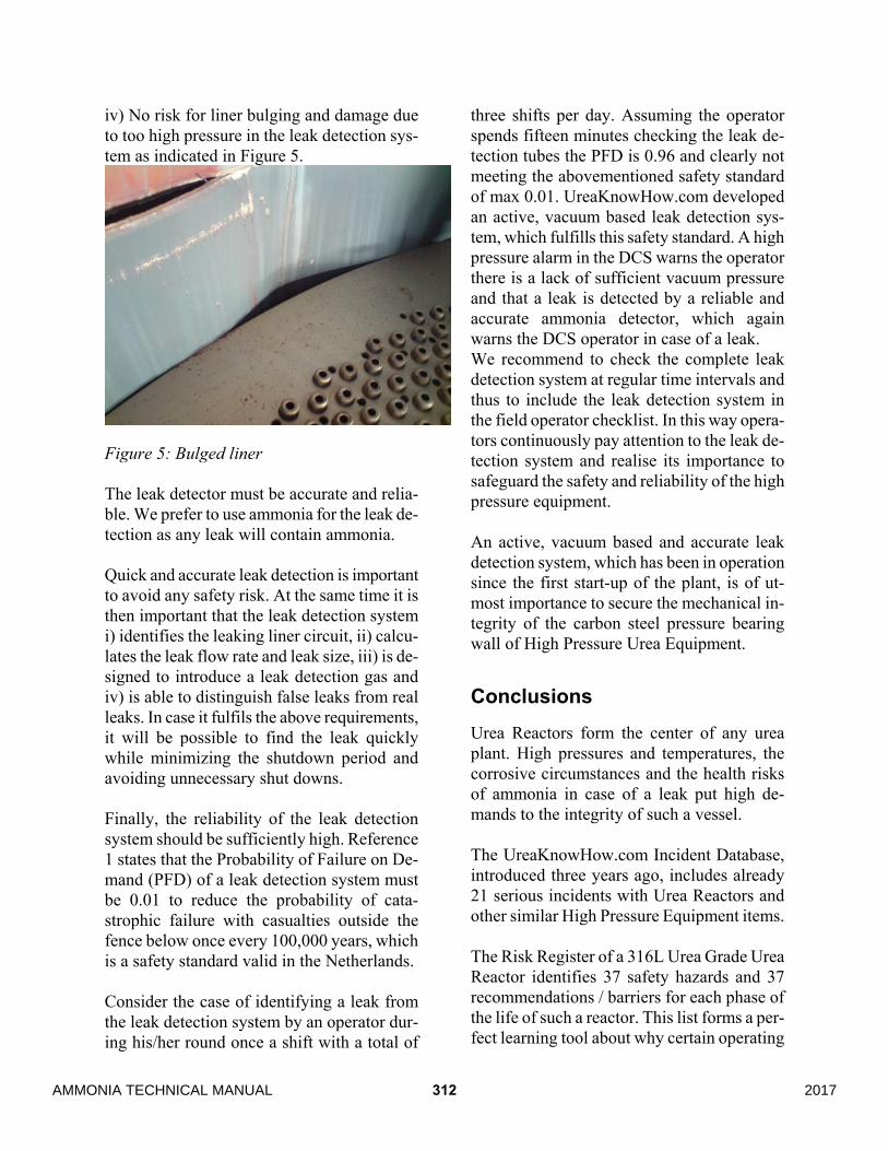
iv) No risk for liner bulging and damage due to too high pressure in the leak detection sys-tem as indicated in Figure 5.
Figure 5: Bulged liner The leak detector must be accurate and relia-ble. We prefer to use ammonia for the leak de-tection as any leak will contain ammonia. Quick and accurate leak detection is important to avoid any safety risk. At the same time it is then important that the leak detection system i) identifies the leaking liner circuit, ii) calcu-lates the leak flow rate and leak size, iii) is de-signed to introduce a leak detection gas and iv) is able to distinguish false leaks from real leaks. In case it fulfils the above requirements, it will be possible to find the leak quickly while minimizing the shutdown period and avoiding unnecessary shut downs. Finally, the reliability of the leak detection system should be sufficiently high. Reference 1 states that the Probability of Failure on De-mand (PFD) of a leak detection system must be 0.01 to reduce the probability of cata-strophic failure with casualties outside the fence below once every 100,000 years, which is a safety standard valid in the Netherlands. Consider the case of identifying a leak from the leak detection system by an operator dur-ing his/her round once a shift with a total of
three shifts per day. Assuming the operator spends fifteen minutes checking the leak de-tection tubes the PFD is 0.96 and clearly not meeting the abovementioned safety standard of max 0.01. UreaKnowHow.com developed an active, vacuum based leak detection sys-tem, which fulfills this safety standard. A high pressure alarm in the DCS warns the operator there is a lack of sufficient vacuum pressure and that a leak is detected by a reliable and accurate ammonia detector, which again warns the DCS operator in case of a leak. We recommend to check the complete leak detection system at regular time intervals and thus to include the leak detection system in the field operator checklist. In this way opera-tors continuously pay attention to the leak de-tection system and realise its importance to safeguard the safety and reliability of the high pressure equipment. An active, vacuum based and accurate leak detection system, which has been in operation since the first start-up of the plant, is of ut-most importance to secure the mechanical in-tegrity of the carbon steel pressure bearing wall of High Pressure Urea Equipment.
Conclusions Urea Reactors form the center of any urea plant. High pressures and temperatures, the corrosive circumstances and the health risks of ammonia in case of a leak put high de-mands to the integrity of such a vessel. The UreaKnowHow.com Incident Database, introduced three years ago, includes already 21 serious incidents with Urea Reactors and other similar High Pressure Equipment items. The Risk Register of a 316L Urea Grade Urea Reactor identifies 37 safety hazards and 37 recommendations / barriers for each phase of the life of such a reactor. This list forms a per-fect learning tool about why certain operating
312 2017AMMONIA TECHNICAL MANUAL

and maintenance procedures are done as they are done. One learns “Why” instead of only “What.” A fact that proves to be unexpectedly enlight-ening is that one can conclude from the Risk Register that 65% of the identified hazards can be mitigated by operating a proper leak detection system. An active, vacuum based and accurate leak detection system, which has been in operation since the first start-up of the plant, is of ut-most importance to secure the mechanical in-tegrity of the carbon steel pressure bearing wall of High Pressure Urea Equipment.
Literature 1) 2014 AICHE Ammonia Safety Con-
ference, Shane Roysum, Yara Belle Plaine Inc., Failure and Repair of the Liner of a High Pressure Carbamate Condenser.
2) Risk Register Urea Reactor link on UreaKnowHow.com.
3132017 AMMONIA TECHNICAL MANUAL

314 2017AMMONIA TECHNICAL MANUAL