rittal handbook 34 - it infrastructure - steven … opens up brand new perspectives for the it...
TRANSCRIPT

Rittal Catalogue 34/IT infrastructure
Courtesy of Steven Engineering, Inc. - (800) 2
IT infrastructure
RiMatrix SStandard room ...........................................................................................400Standard security room ..............................................................................401Standard container .....................................................................................402
IT enclosure systemsTS IT with vented door for room climate control............................................90TS IT with glazed door for rack climate control..............................................92TS IT with glazed door for rack climate control, pre-configured.....................94TS IT with glazed door for rack climate control, IP 55 ...................................95Data Rack distributor frame ..........................................................................96
IT enclosuresVerticalBox ...................................................................................................97FlatBox .........................................................................................................98Wall-mounted enclosure EL, 3-part, pre-configured with mounting angles..................................................................................100Wall-mounted enclosure EL, 3-part, with punched rails and mounting angles .....................................................101Wall-mounted enclosure EL, 3-part, with mounting plate and mounting angles ..................................................................................102Wall-mounted enclosures AE with 482.6 mm (19˝) mounting angles............104Small fibre-optic distributor with mounting plate and splicing cassette holder .......................................................................105
IT powerPower Distribution Rack/Module.................................................................408Power System Module................................................................................409Power Distribution Unit ...............................................................................414MID measurement module for CMC III ........................................................421Power supply..............................................................................................422
IT coolingLiquid Cooling Package ..............................................................................428Aisle containment .......................................................................................435Roof-mounted cooling unit for cooling IT equipment ...................................436Small cooling units......................................................................................437Chillers for IT cooling ..................................................................................441
IT monitoringCMC III – Monitoring system.......................................................................446Door control system ...................................................................................459Monitor/keyboard unit.................................................................................461Dynamic Rack Control ................................................................................462Management software ................................................................................463
IT security solutionsMicro Data Centre ......................................................................................466Climate control for Micro Data Centre .........................................................469Data Centre Container ................................................................................472Fire alarm and extinguisher system DET-AC/EFD Plus ................................473Security rooms ...........................................................................................474
387
58-9200 - [email protected] - www.stevenengineering.com
388
Courtesy of Steven Engineering, Inc. - (800) 258-9200 - sales@steve
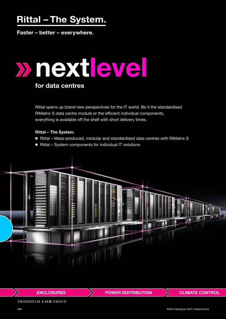
nextlevelfor data centres
Rittal opens up brand new perspectives for the IT world. Be it the standardised RiMatrix S data centre module or the efficient individual components, everything is available off the shelf with short delivery times.
Rittal – The System. ◾ Rittal – Mass-produced, modular and standardised data centres with RiMatrix S◾ Rittal – System components for individual IT solutions
Rittal Catalogue 34/IT infrastructure
neng.com - www.stevenengineering.com

nextlevelfor data centres
389Rittal Catalogue 34/IT infrastructure
Courtesy of Steven Engineering, Inc. - (800) 258-9200 - [email protected] - www.stevenengineering.com

IT infrastructure from the smallest to the largest◾ RiMatrix S◾ IT enclosure systems◾ IT enclosures◾ IT power◾ IT cooling◾ IT monitoring◾ IT security solutions
390 Rittal Catalogue 34/IT infrastructure
Courtesy of Steven Engineering, Inc. - (800) 258-9200 - [email protected] - www.stevenengineering.com

◾ RiMatrix S – The first mass-produced data centre, tested and documented modules◾ IT security rooms – Certified to ECB·S
391Rittal Catalogue 34/IT infrastructure
Courtesy of Steven Engineering, Inc. - (800) 258-9200 - [email protected] - www.stevenengineering.com

392 Rittal Catalogue 34/IT infrastructure
Your benefits with RiMatrixUnique IT system solutions from Rittal provide state-of-the-art data centre infrastructures. Flexibly select your standardised components from the RiMatrix system components IT enclosure systems/enclosures, IT power, IT cooling, IT monitoring and IT security solutions. In this way, the IT infrastructure may be tailored precisely to your requirements – leaving plenty of flexibility for future expansion.
Faster – Precise-fit data centre infrastructures with “Rittal – The System.”Better – Standardised, coordinated system components Everywhere – Commissioning by our 1,000 international service engineers
Courtesy of Steven Engineering, Inc. - (800) 258-9200 - [email protected] - www.stevenengineering.com

393Rittal Catalogue 34/IT infrastructure
Courtesy of Steven Engineering, Inc. - (800) 258-9200 - [email protected] - www.stevenengineering.com

394 Rittal Catalogue 34/IT infrastructure
Your benefits with RiMatrix SRiMatrix S is the revolutionary alternative in data centre construction. Based on pre-configured, complete data centre modules, it supports the creation of standardised data centre infrastructures. The data centre modules already contain all the essential components, such as IT enclosure systems, power back-up and distribution, cooling, monitoring and security solutions. All data centre modules are pre-manufactured, available off the shelf, and permit fast configuration of coordinated customer solutions.
Faster – Pre-configured data centre modules available off the shelfBetter – Tested and documented data centre modules with outstanding efficiencyEverywhere – Installation in system-tested security rooms, standard aisle containment or containers
Courtesy of Steven Engineering, Inc. - (800) 258-9200 - [email protected] - www.stevenengineering.com
395Rittal Catalogue 34/IT infrastructure
Courtesy of Steven Engineering, Inc. - (800) 258-9200 - [email protected] - www.stevenengineering.com

396
Courtesy of Steven Engineering, Inc. - (800) 258-9200 - [email protected] - www.stevenengineering.com

Rittal Catalogue 34/IT infrastructure
Courtesy of Steven Engineering, Inc. - (800) 2
RiMatrix S
RiMatrix S RiMatrix S at a glance.................................................................................398Standard room ...........................................................................................400Standard security room ..............................................................................401Standard container .....................................................................................402
Your benefits◾ Standardised data centre infrastructures based
on data centre modules◾ Tested and documented modules with outstanding efficiency◾ Simplified planning with pre-configuration◾ Available off the shelf ◾ Guaranteed efficiency ratings (PuE)◾ Simplified service and administration processes
58-9200 - [email protected]
RiMatrix S AppYour configurator for standardised data centres for SMEs, branch con-cepts and flexible cloud applications. A simple user interface will guide you to your complete data centre in just five steps.
397
- www.stevenengineering.com

iMatrix S at a glance
RStandard roomIntegration of RiMatrix S modules into an existing property.
In order to achieve optimum air routing, precise-fit aisle containment is included with the supply.
Aisle containment is a combination of door and roof components which allow consistent separation of the hot and cold air.
– Enhanced energy efficiency – Superior output density, due to guaranteed
cold air supply – Dust- and water-tight in the protected area
above the raised floor, IP 20 to IEC 60 529
Single 6 Double 6 Single 9 Double 9 Model No. 7998.106 7998.107 7998.406 7998.407 Fire protection – Burglar resistance – Acrid gas-tightness – Dust and water protection –Early fire detection ◾ Room extinguisher system OptionalHumidification and dehumidification system Optional External dimensionsWidth mm 2828 4854 2828 4854Height mm 2750 2750 2750 2750Depth mm 7080 7080 7080 7080Rack configurationServer enclosure (600 x 2000 x 1200 mm) 6 pc(s). 12 pc(s). 8 pc(s). 16 pc(s).
Combined network server enclosure (800 x 2000 x 1200 mm) 1 pc(s). 2 pc(s). 1 pc(s). 2 pc(s).
Uninterruptible power supply (Partner product, see note on page 407) 60 kW + 20 kW 2 x (60 kW + 20 kW) – –
398 Rittal Catalogue 34/IT infrastructure
Courtesy of Steven Engineering, Inc. - (800) 258-9200 - [email protected] - www.stevenengineering.com
RiMatrix S at a glance
S
–
–
–––
–
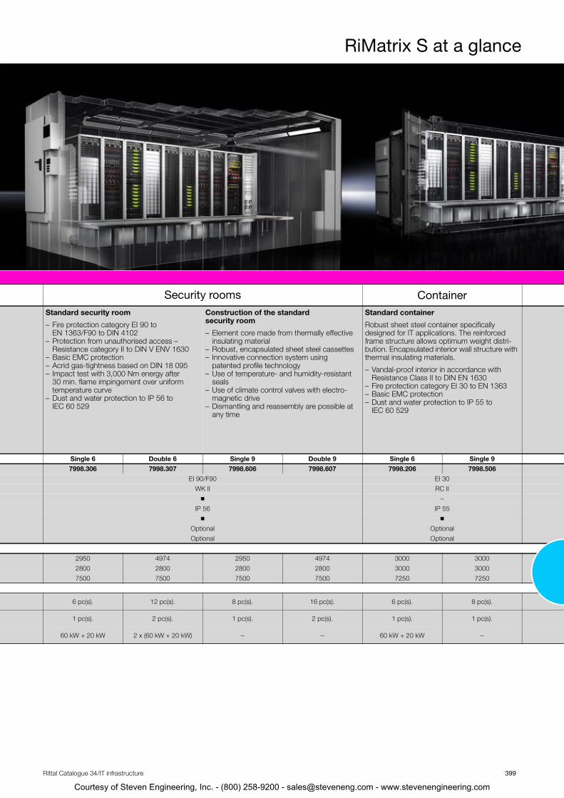
Security rooms Containertandard security room
Fire protection category EI 90 to EN 1363/F90 to DIN 4102 Protection from unauthorised access – Resistance category II to DIN V ENV 1630Basic EMC protection Acrid gas-tightness based on DIN 18 095 Impact test with 3,000 Nm energy after 30 min. flame impingement over uniform temperature curveDust and water protection to IP 56 to IEC 60 529
Construction of the standard security room
– Element core made from thermally effective insulating material
– Robust, encapsulated sheet steel cassettes – Innovative connection system using
patented profile technology – Use of temperature- and humidity-resistant
seals – Use of climate control valves with electro-
magnetic drive – Dismantling and reassembly are possible at
any time
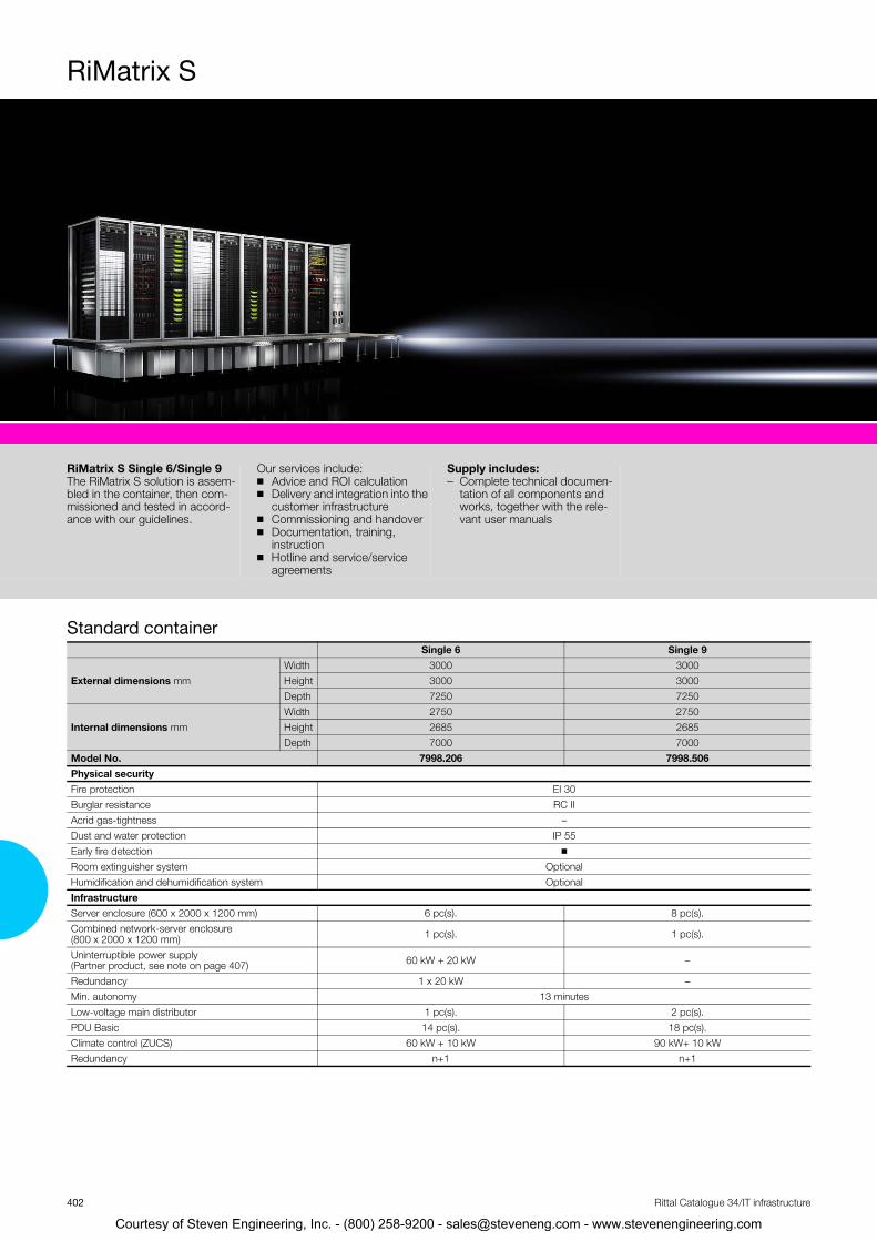
Standard container
Robust sheet steel container specifically designed for IT applications. The reinforced frame structure allows optimum weight distri-bution. Encapsulated interior wall structure with thermal insulating materials.
– Vandal-proof interior in accordance with Resistance Class II to DIN EN 1630
– Fire protection category EI 30 to EN 1363– Basic EMC protection – Dust and water protection to IP 55 to
IEC 60 529
Single 6 Double 6 Single 9 Double 9 Single 6 Single 9 7998.306 7998.307 7998.606 7998.607 7998.206 7998.506
EI 90/F90 EI 30WK II RC II
◾ – IP 56 IP 55
◾ ◾ Optional Optional Optional Optional
2950 4974 2950 4974 3000 30002800 2800 2800 2800 3000 30007500 7500 7500 7500 7250 7250
6 pc(s). 12 pc(s). 8 pc(s). 16 pc(s). 6 pc(s). 8 pc(s).
1 pc(s). 2 pc(s). 1 pc(s). 2 pc(s). 1 pc(s). 1 pc(s).
60 kW + 20 kW 2 x (60 kW + 20 kW) – – 60 kW + 20 kW –
399Rittal Catalogue 34/IT infrastructure
Courtesy of Steven Engineering, Inc. - (800) 258-9200 - [email protected] - www.stevenengineering.com
iMatrix S
RS
R◾
◾
◾
◾
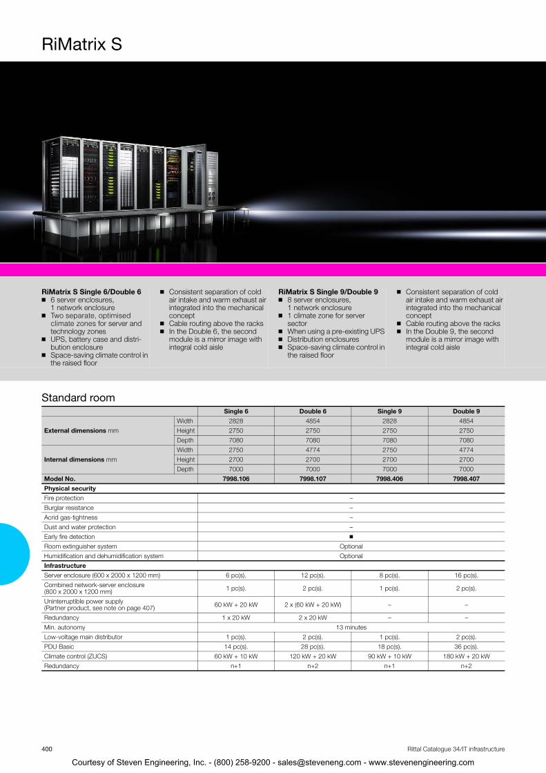
iMatrix S Single 6/Double 66 server enclosures, 1 network enclosureTwo separate, optimised climate zones for server and technology zonesUPS, battery case and distri-bution enclosureSpace-saving climate control in the raised floor
◾ Consistent separation of cold air intake and warm exhaust air integrated into the mechanical concept
◾ Cable routing above the racks◾ In the Double 6, the second
module is a mirror image with integral cold aisle
RiMatrix S Single 9/Double 9◾ 8 server enclosures,
1 network enclosure◾ 1 climate zone for server
sector◾ When using a pre-existing UPS ◾ Distribution enclosures◾ Space-saving climate control in
the raised floor
◾ Consistent separation of cold air intake and warm exhaust air integrated into the mechanical concept
◾ Cable routing above the racks◾ In the Double 9, the second
module is a mirror image with integral cold aisle
tandard roomSingle 6 Double 6 Single 9 Double 9
External dimensions mm Width 2828 4854 2828 4854Height 2750 2750 2750 2750Depth 7080 7080 7080 7080
Internal dimensions mm Width 2750 4774 2750 4774Height 2700 2700 2700 2700Depth 7000 7000 7000 7000
Model No. 7998.106 7998.107 7998.406 7998.407Physical security Fire protection – Burglar resistance – Acrid gas-tightness – Dust and water protection – Early fire detection ◾ Room extinguisher system OptionalHumidification and dehumidification system OptionalInfrastructure Server enclosure (600 x 2000 x 1200 mm) 6 pc(s). 12 pc(s). 8 pc(s). 16 pc(s). Combined network-server enclosure (800 x 2000 x 1200 mm) 1 pc(s). 2 pc(s). 1 pc(s). 2 pc(s).
Uninterruptible power supply(Partner product, see note on page 407) 60 kW + 20 kW 2 x (60 kW + 20 kW) – –
Redundancy 1 x 20 kW 2 x 20 kW – – Min. autonomy 13 minutesLow-voltage main distributor 1 pc(s). 2 pc(s). 1 pc(s). 2 pc(s). PDU Basic 14 pc(s). 28 pc(s). 18 pc(s). 36 pc(s). Climate control (ZUCS) 60 kW + 10 kW 120 kW + 20 kW 90 kW + 10 kW 180 kW + 20 kWRedundancy n+1 n+2 n+1 n+2
400 Rittal Catalogue 34/IT infrastructure
Courtesy of Steven Engineering, Inc. - (800) 258-9200 - [email protected] - www.stevenengineering.com

RiMatrix S
S
R◾
◾
◾
◾
tandard security roomSingle 6 Double 6 Single 9 Double 9
iMatrix S Single 6/Double 66 server enclosures, 1 network enclosureTwo separate, optimised climate zones for server and technology zonesUPS, battery case and distri-bution enclosureSpace-saving climate control in the raised floor
◾ Consistent separation of cold air intake and warm exhaust air integrated into the mechanical concept
◾ Cable routing above the racks◾ In the Double 6, the second
module is a mirror image with integral cold aisle
RiMatrix S Single 9/Double 9◾ 8 server enclosures,
1 network enclosure◾ 1 climate zone for server
sector◾ When using a pre-existing UPS◾ Distribution enclosures◾ Space-saving climate control in
the raised floor
◾ Consistent separation of cold air intake and warm exhaust air integrated into the mechanical concept
◾ Cable routing above the racks◾ In the Double 9, the second
module is a mirror image with integral cold aisle
External dimensions mm Width 2950 4974 2950 4974Height 2800 2800 2800 2800Depth 7500 7500 7500 7500
Internal dimensions mm Width 2750 4774 2750 4774Height 2700 2700 2700 2700Depth 7300 7300 7300 7300
Model No. 7998.306 7998.307 7998.606 7998.607Physical security Fire protection EI 90/F90 Burglar resistance WK IIAcrid gas-tightness ◾ Dust and water protection IP 56 Early fire detection ◾ Room extinguisher system Optional Humidification and dehumidification system OptionalInfrastructureServer enclosure (600 x 2000 x 1200 mm) 6 pc(s). 12 pc(s). 8 pc(s). 16 pc(s). Combined network-server enclosure (800 x 2000 x 1200 mm) 1 pc(s). 2 pc(s). 1 pc(s). 2 pc(s).
Uninterruptible power supply(Partner product, see note on page 407) 60 kW + 20 kW 2 x (60 kW + 20 kW) – –
Redundancy 1 x 20 kW 2 x 20 kW – – Min. autonomy 13 minutesLow-voltage main distributor 1 pc(s). 2 pc(s). 1 pc(s). 2 pc(s). PDU Basic 14 pc(s). 28 pc(s). 18 pc(s). 36 pc(s). Climate control (ZUCS) 60 kW + 10 kW 120 kW + 20 kW 90 kW + 10 kW 180 kW + 20 kWRedundancy n+1 n+2 n+1 n+2
401Rittal Catalogue 34/IT infrastructure
Courtesy of Steven Engineering, Inc. - (800) 258-9200 - [email protected] - www.stevenengineering.com
iMatrix S
RS
RThblman
tandard container
iMatrix S Single 6/Single 9e RiMatrix S solution is assem-
ed in the container, then com-issioned and tested in accord-ce with our guidelines.
Our services include: ◾ Advice and ROI calculation ◾ Delivery and integration into the
customer infrastructure ◾ Commissioning and handover ◾ Documentation, training,
instruction ◾ Hotline and service/service
agreements
Supply includes: – Complete technical documen-
tation of all components and works, together with the rele-vant user manuals
Single 6 Single 9
External dimensions mm Width 3000 3000Height 3000 3000Depth 7250 7250
Internal dimensions mm Width 2750 2750Height 2685 2685Depth 7000 7000
Model No. 7998.206 7998.506Physical security Fire protection EI 30Burglar resistance RC IIAcrid gas-tightness –Dust and water protection IP 55 Early fire detection ◾ Room extinguisher system OptionalHumidification and dehumidification system OptionalInfrastructureServer enclosure (600 x 2000 x 1200 mm) 6 pc(s). 8 pc(s). Combined network-server enclosure (800 x 2000 x 1200 mm) 1 pc(s). 1 pc(s).
Uninterruptible power supply(Partner product, see note on page 407) 60 kW + 20 kW –
Redundancy 1 x 20 kW – Min. autonomy 13 minutesLow-voltage main distributor 1 pc(s). 2 pc(s). PDU Basic 14 pc(s). 18 pc(s). Climate control (ZUCS) 60 kW + 10 kW 90 kW+ 10 kWRedundancy n+1 n+1
402 Rittal Catalogue 34/IT infrastructure
Courtesy of Steven Engineering, Inc. - (800) 258-9200 - [email protected] - www.stevenengineering.com

403
The first mass-produced data centre. Simply plug in and it’s ready to use.
RiMatrix S SelectorYour solution is configured on the basis of standardised data centre modules.
◾ The planning phase, delivery and commissioning times are significantly shortened
◾ A precise efficiency calculation (including consumption figures) is always included as part of our consulting service, based on the data sheet
◾ Standardisation leads to significant potential savings
◾ The data centre modules are complete functional units (including electricity, cooling supply and monitoring)
◾ The modules are comprehensively measured and have a data sheet,and can therefore be ordered off the shelf using a model number
RiMatrix S AppYour configurator for standardised data centres for SMEs, sector concepts and flexible cloud applications.
An intuitive user interface will guide you to your complete data centre in five easy steps:
1. Requirements and peripheral conditions2. Technical specifications 3. Standardised module selection4. Optional packages5. Your RiMatrix S solution
Courtesy of Steven Engineering, Inc. - (800) 258-9200 - [email protected] - www.stevenengineering.com

404 Rittal Catalogue 34/IT infrastructure
31
4
4
2
2
6
Courtesy of Steven Engineering, Inc. - (800) 258-9200 - [email protected] - www.stevenengineering.com
Rittal Catalogue 34/IT infrastructure
5
Courtesy of Steven Engineering, Inc. - (800) 2
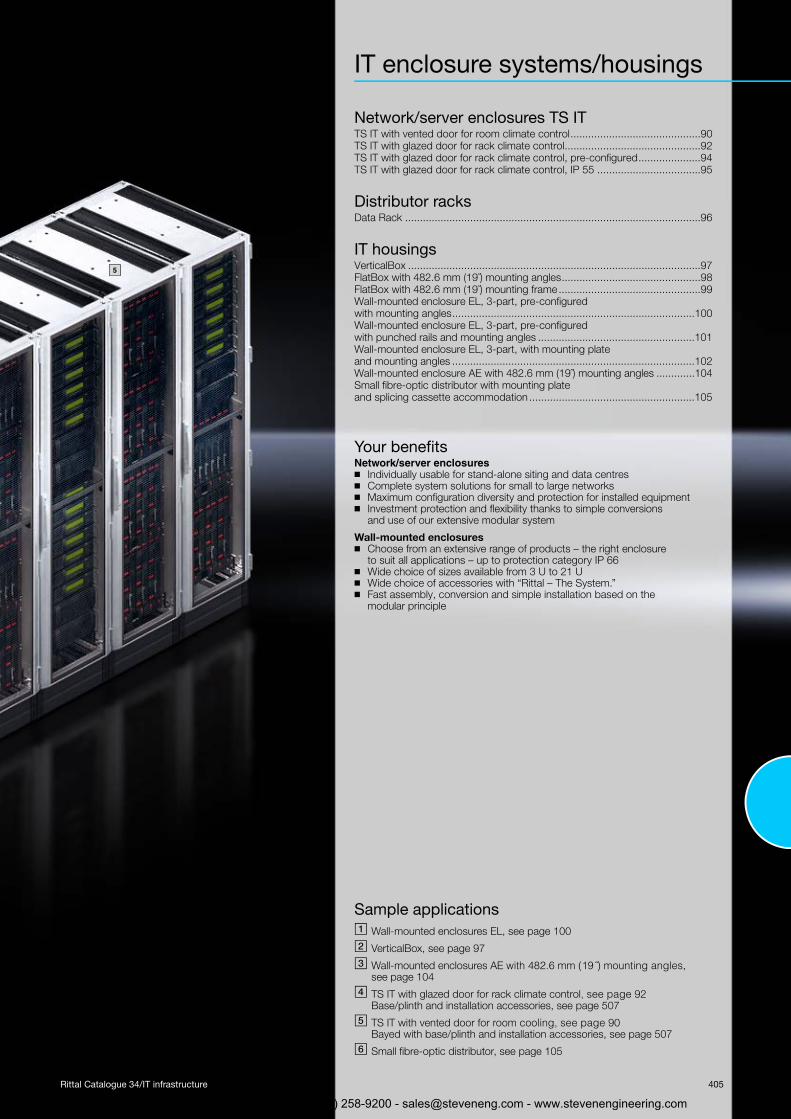
IT enclosure systems/housings
Network/server enclosures TS ITTS IT with vented door for room climate control............................................90TS IT with glazed door for rack climate control..............................................92TS IT with glazed door for rack climate control, pre-configured.....................94TS IT with glazed door for rack climate control, IP 55 ...................................95
Distributor racksData Rack ....................................................................................................96
IT housingsVerticalBox ...................................................................................................97FlatBox with 482.6 mm (19˝) mounting angles...............................................98FlatBox with 482.6 mm (19˝) mounting frame................................................99Wall-mounted enclosure EL, 3-part, pre-configured with mounting angles..................................................................................100Wall-mounted enclosure EL, 3-part, pre-configured with punched rails and mounting angles .....................................................101Wall-mounted enclosure EL, 3-part, with mounting plate and mounting angles ..................................................................................102Wall-mounted enclosure AE with 482.6 mm (19˝) mounting angles .............104Small fibre-optic distributor with mounting plate and splicing cassette accommodation ........................................................105
Your benefitsNetwork/server enclosures ◾ Individually usable for stand-alone siting and data centres◾ Complete system solutions for small to large networks◾ Maximum configuration diversity and protection for installed equipment◾ Investment protection and flexibility thanks to simple conversions
and use of our extensive modular system
Wall-mounted enclosures◾ Choose from an extensive range of products – the right enclosure
to suit all applications – up to protection category IP 66◾ Wide choice of sizes available from 3 U to 21 U ◾ Wide choice of accessories with “Rittal – The System.”◾ Fast assembly, conversion and simple installation based on the
modular principle
Sample applications� Wall-mounted enclosures EL, see page 100
� VerticalBox, see page 97
� Wall-mounted enclosures AE with 482.6 mm (19˝) mounting angles, see page 104
� TS IT with glazed door for rack climate control, see page 92Base/plinth and installation accessories, see page 507
� TS IT with vented door for room cooling, see page 90Bayed with base/plinth and installation accessories, see page 507
Small fibre-optic distributor, see page 105
405
58-9200 - [email protected] - www.stevenengineering.com

406 Rittal Catalogue 34/IT infrastructure
4 1
2
5
Courtesy of Steven Engineering, Inc. - (800) 258-9200 - [email protected] - www.stevenengineering.com

Rittal Catalogue 34/IT infrastructure
3
Courtesy of Steven Engineering, Inc. - (800) 2
IT power
Power Distribution RackPower Distribution Rack PDR .....................................................................408Power Distribution Module PDM .................................................................408
Power System ModulePSM busbars..............................................................................................409PSM measurement bar for CMC III .............................................................410PSM socket modules..................................................................................411PCU Power Control Unit .............................................................................412PSM accessories........................................................................................413MID measurement module for CMC III ........................................................421
Power Distribution UnitPDU international........................................................................................414PDU UK......................................................................................................418PDU accessories ........................................................................................418PDU configuration ......................................................................................419PDU sample applications............................................................................420
Power supplySocket strips ..............................................................................................422
Your benefits◾ Holistic, systematic energy management concepts◾ Comprehensive, complete solutions for power distribution and back-up,
consistently modular, and flexibly extendible at any time◾ Optimum energy and cost efficiency with maximum availability of the
entire system◾ Reduced installation, administration and manpower costs◾ High level of investment security◾ All from a single partner
Sample applications� Power Distribution Rack PDR, see page 408
� Power Distribution Module PDM, see page 408
� Power System Module PSM, see page 409
� Power distribution, see page 197
� UPS (partner product)
5
Please note:Rittal has decided to stop offering its own single-phase and three-phase UPS systems. Instead, from now on, we are collaborating with a few selected product partners and recommending them for use in system solu-tions and IT projects.
The advantages for our customers are as follows: ◾ Independent selection of the best UPS systems from a technical and
financial perspective, depending on the technical requirements and regional framework conditions
◾ Clear regulation of the customer/supplier relationship in terms of procurement, installation, commissioning and services
◾ Clear regulation of warranties and product liability
For our chosen product partners, Rittal provides key basic information (such as technical properties, ordering instructions, contact addresses and other details, where applicable). Further details can be found on our website at www.rittal.com.
407
8-9200 - [email protected] - www.stevenengineering.com

ower Distribution Rack
PPo◾
◾
◾
◾
◾◾
wer Distribution Rack PDRTo accommodate a maximum of 8 PDM Height 1.20 m for 4 PDM and 2 m height for 8 PDM PDM may be retrofitted whilst operational A maximum of 32 racks may be fitted to the sub-distributor Fully shock hazard-protected Master switch in various con-figurations: – Isolator switch– Fuse-switch disconnector– Air circuit-breaker– RC circuit-breaker
◾ Low-voltage distribution up to 250 A
Material: – Sheet steel
Surface finish: – Enclosure frame: Dipcoat-
primed – Doors, roof and base/plinth:
Dipcoat-primed, powder-coated
– Gland plates, punched sec-tions with mounting flanges and mounting angles: Zinc-plated, clear chromated
Colour: – RAL 7035
Supply includes: – Enclosure frame with door
(without tubular door frame) – Rear panel – Side panels and roof plate – Levelling feet incl. base/plinth
adaptor – Earthing of all enclosure panels – Busbars shock-hazard-
protected – Integral master switch
Note:– Observe the standards of the
local electricity supply compa-nies
Approvals:– VDE
Technical details:Available on the Internet
Power Distribution Module PDM◾ Mechanically latchable in the
PDR ◾ Scalable◾ RC circuit-breaker, optional
Supply includes: – 482.6 mm/19˝ module, 3 U – Master switch – 4 fused 3-phase outlets to the
rack– 3 x 230 V/16 A per outlet– Connected load 400 V, 3 AC,
max. 63 A
Photo shows a configuration example with equipment not included in the scope of supply
Power Distribution Rack PDR
Power Distribution Module PDM
Packs ofPossible number of PDM modules 4 8Width mm 800 800Height mm 1200 2000Depth mm 500 500Model No. 1 pc(s). 7857.310 7857.300 AccessoriesFlex-Block base/plinth system see page 510 TS base/plinth see page 512
U Packs of 3Configuration 4 outlets per 10 kWWidth mm 482.6 (19˝)Height mm 133.4 Depth mm 350Model No. 1 pc(s). 7857.320Also required
Plug and play connection cable for PSM busbar to the server enclosures
Length 3 m 1 pc(s). 7857.130Length 5 m 1 pc(s). 7857.150Length 9 m 1 pc(s). 7857.190
408 Rittal Catalogue 34/IT infrastructure
Courtesy of Steven Engineering, Inc. - (800) 258-9200 - [email protected] - www.stevenengineering.com

Power System Module
409
1
2
3
4
tevenengineering.com
PSM busbars
Rittal Catalogue 34/IT infrastructure
PSM busbars + PSM socket modulesPSM busbarsThe modular system facilitates basic configuration of the racks, thanks to a vertical support rail with single-/3-phase infeed. The various socket modules to supply the active components may be snap-fitted into the support rail. This can even be done whilst the system is operational, because the support section is shock hazard-protected.
PSM socket modulesThe various modules, earthing pins, IEC320 etc. may be inserted into the support rail in any combi-nation. This is easily achieved, even by non-electri-cians, thanks to the shock-hazard-protected plug & play system.
Approvals:Available on the Internet
Photo shows a configuration example with equip-ment not included in the scope of supply
Technical specifications/benefits: ◾ Each socket module picks off a phase on the
support rail, either from infeed A or from the redundant infeed B, depending on the direction of connection
◾ Single-/3-phase construction with a maximum current of 2 x (3 x 16 A)
◾ 3-phase redundant infeed supported ◾ The redundant circuit is completely separate from
the 3 phases of the support rail ◾ Modules may be retrofitted whilst operational ◾ Modules may be equipped with integral overcur-
rent protection, so that only the affected module is deactivated in the event of an excessively high current; the other modules remain operational
◾ Overvoltage protection may be integrated into the supply line
◾ Various modules also available with current measurement and switchable outputs
AB
Circuit reversal by rotating the PSM module
PSM busbars
Also required:– PSM socket modules, see page 411
Accessories:
– Mounting kit for PSM busbars, see page 413 – Connection cables, see page 413 – Cable lock, see page 413 – Overvoltage protection, see page 413
For enclosure
height mm
Phases per
infeed
No. of infeeds
Input current (A)
Max. no. of
moduleslots
Connection, connector
type
Circuit breaker
16 A Packs of Model No.
� With measurement of voltage, current and power (consumption) via CMC, remote-controllable
2000 3 2 16 6 Wago X-COM – 1 pc(s). 7859.0502000 1 1 32 6 CEE 2 1 pc(s). 7859.053
� With 2 infeeds (jack), 3-phase redundancy
1200 3 2 16 4 Wago X-COM – 1 pc(s). 7856.0102000 3 2 16 7 Wago X-COM – 1 pc(s). 7856.0202200 3 2 16 8 Wago X-COM – 1 pc(s). 7856.008
� With 3 m connection cable (connector type CEE/EN 60 309)
2000 3 1 16 7 CEE – 1 pc(s). 7856.0052000 3 2 16 7 CEE – 1 pc(s). 7856.006
� With 3 m connection cable (connector type CEE/EN 60 309)
2000 1 1 32 6 CEE 2 1 pc(s). 7856.3212000 3 1 32 6 CEE 6 1 pc(s). 7856.323
Courtesy of Steven Engineering, Inc. - (800) 258-9200 - [email protected] - www.s

Power System Module
410
Courtesy of Steven Eng
PSM measurement bar for CMC IIIMeasurement bars for direct connection to the CMC III system. With a PSM mounting kit, the measurement bar may be vertically mounted in a 2000 mm high TS 8 or in the TS IT rack. Display and monitoring of all major output parame-ters is supported, separated by phase and infeed. An integral display provides a local on-site display in the rack. Remote administration and network connectivity are created via the CMC III system.
Benefits: ◾ Modular extendible system◾ For 16 A and 32 A phase current◾ Various PSM connection modules (pin patterns)◾ PSM modules may be connected with the sys-
tem operational ◾ VDE-tested, shock hazard-protected system◾ Easy to assemble◾ CAN bus for connection to CMC III system◾ Extensive management and monitoring functions
(via CMC III)◾ High-MTBF and measurement accuracy of 1%◾ Energy-efficient electric design – minimal
inherent power consumption◾ High-quality aluminium housing, for flexible
mounting
Measurement functions: – Voltage (V), current (A), frequency (Hz)– Active power (kW), active energy (kWh),
apparent power (VA), apparent energy (kVAh)– Power factor (cos phi) – Zero conductor measurement/load imbalance
detection– Measurement per phase or infeed– Measurement accuracy 1% (kWh)
to IEC 50 430-1
Material: – Extruded aluminium section, anodised
Protection category IP to IEC 60 529: – IP 20
Standards:– EN 60 950– EN 61 000-6-1– EN 61 000-6-2– EN 55 022
Safety directive: – 2006/95/EC
EMC directive: – 2004/108/EC
Approvals: Available on the Internet
Photograph shows a configuration example with equipment not included in the scope of supply
Model No. 7859.050 7859.053 PageVersion/rated current A (per phase) 16 32 No. of infeeds (3-phase, 16 A/single-phase, 32 A) 2 1Connection cable, plug-in, various configurations ◾ – Connection cable, static, 3 m, with CEE connector, 32 A, single-phase (IEC 60 309) – ◾
Electromagnetic circuit-breaker (2 x 16 A, type C) – ◾ Input voltage 230 V/400 V (50/60 Hz) ◾ ◾ Power supply via CMC III system (24 V DC) ◾ ◾ CAN bus for direct connection to CMC III system (RJ 45, 2 x socket) ◾ ◾ Maximum no. of systems that may be connected to one CMC-PU III 8 8Ambient conditionsOperating temperature 0°C…+45°C Storage temperature -25°C…+70°C Ambient humidity % (non-condensing) 10 – 95AccessoriesPSM connection cable, 3-phase, with CEE connectors (IEC 60 309), length 3 m (2 x required when using both infeeds) 7856.025 Fixed installation 413
PSM mouting kit for mounting on the TS IT enclosure frame, height 2000 mm 7856.029 7856.029 413
PSM module 4 x earthing-pin, black 7856.100 7856.100 411 PSM module 4 x earthing-pin, red 7856.240 7856.240 411 PSM module 6 x C13 7856.080 7856.080 411 PSM module 4 x C19 7856.230 7856.230 411 Other PSM socket modules see page 411
inee
PSM measurement bar
Rittal Catalogue 34/IT infrastructure
ring, Inc. - (800) 258-9200 - [email protected] - www.stevenengineering.com

Power System Module
411
1
2
3
4
5
tevenengineering.com
PSM socket modules
Rittal Catalogue 34/IT infrastructure
PSM socket modules
Approvals:Available on the Internet
Required module slots
in PSM busbarConnector pattern Slots
Thermal overcurrent protection
Packs of Model No.
� Standard socket modules/non-switchable
1 C13 6 – 1 pc(s). 7856.0801 C13 6 ◾ 1 pc(s). 7856.0701 C13 4 ◾/per output 1 pc(s). 7856.2201 Earthing-pin 320/CEE 7/4 4 – 1 pc(s). 7856.1001 Earthing-pin 320/CEE 7/4 4 ◾ 1 pc(s). 7856.0901 C19 4 – 1 pc(s). 7856.2301 C13 red 6 – 1 pc(s). 7856.0821 Earthing-pin, red 4 – 1 pc(s). 7856.240
� Socket modules, international
1 France/Belgium/CEE 7/5 4 – 1 pc(s). 7856.1201 Switzerland 5 – 1 pc(s). 7856.190
� Socket modules with LED display/current measurement per module
1 C13 6 – 1 pc(s). 7859.1201 C19 4 – 1 pc(s). 7859.130
� Socket modules with switchable slot/aggregate current measurement per module
2 C13 8 ◾ 1 pc(s). 7856.2012 Earthing-pin 320/CEE 7/4/C13 4/2 ◾ 1 pc(s). 7856.2032 C19/C13 4/2 ◾ 1 pc(s). 7856.204
� Socket modules with switchable slot/individual current measurement per slot
2 Earthing-pin 320/CEE 7/4/C13 4/2 ◾ 1 pc(s). 7859.2122 C13 8 ◾ 1 pc(s). 7859.2222 C19/C13 4/2 ◾ 1 pc(s). 7859.232
Courtesy of Steven Engineering, Inc. - (800) 258-9200 - [email protected] - www.s
Power System Module
412
Courtesy of Steven En
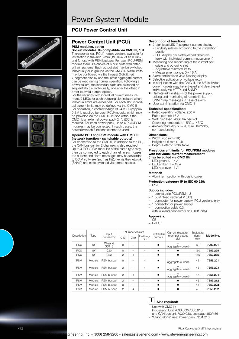
Power Control Unit (PCU) PSM modules, active Socket modules, IP-compatible via CMC III, 1 UThere are various PCU/module versions available for installation in the 482.6 mm (19˝) level of an IT rack and for use with PSM busbars. For each PCU/PSM module there is a choice of 6 or 8 slots with differ-ent pin patterns. Each output slot may be switched individually or in groups via the CMC III. Alarm limits may be configured via the integral 2-digit, red 7-segment display and the latest aggregate current can be read during normal operation. Following a power failure, the individual slots are switched on sequentially (i.e. individually, one after the other) in order to avoid current spikes. For the versions with individual current measure-ment, 2 LEDs for each outgoing slot indicate when individual limits are exceeded. For each slot, individ-ual current limits may be defined via the CMC III. For operation, a control voltage of 24 V (DC)/approx. 0.2 A is required for each PCU/module, which may be provided via the CMC III. If used without the CMC III, an external power pack 24 V (DC) is required. For each power pack, up to 4 PCU/PSM modules may be connected. In such cases, the network/switch functions cannot be used.
Operate PCU and PSM module with CMC III (network function – switchable outputs)For connection to the CMC III, in addition to the PU, the CAN bus unit for 2 channels is also required. Up to 4 PCU/PSM modules of the same type may then be connected to each channel. In such cases, the current and alarm messages may be forwarded to DCIM software (such as RiZone) via the network (SNMP) and slots switched via remote access.
Description of functions: ◾ 2-digit local LED 7-segment current display
– Legibility rotates according to the installation position
– LED display per slot/overload detection (only with individual current measurement)
◾ Measuring and monitoring of the current per module and outgoing slot – Adjustable min/max limits – Measurement range: 0 – 16 A
◾ Alarm notifications via a flashing display◾ Selective activation on voltage return◾ In conjunction with the CMC III, the 6/8 individual
current outlets may be activated and deactivated individually via HTTP and SNMP
◾ Remote administration of the power supply, editing and monitoring of remote limits, SNMP trap messages in case of alarm
◾ User administration via CMC III
Technical specifications: – Rated operating voltage: 250 V – Rated current: 16 A– Switching load: 4000 VA per slot– Operating temperature +5°C...+45°C – Ambient humidity 50 – 95% rel. humidity,
non-condensing
Dimensions: – Width: 465 mm (19˝)– Height: 44.5 mm (1 U)– Depth: Refer to order table
Preset current limits for PCU/PSM modules with individual current measurement (may be edited via CMC III): – LED green: 0 – 7 A – LED amber: 7 – 13 A– LED red: over 13 A
Material: – Aluminium section with plastic cover
Protection category IP to IEC 60 529: – IP 20
Supply includes: – 1 socket strip PCU/PSM 1U– 1 bus/infeed cable 24 V (DC) – 1 connector for power supply (PCU versions only)– 1 connector for power supply – 1 connection cable 0.3 m
with Wieland connector (7200.001 only)
Approvals: – CE – RoHS
Rittal Catalogue 34/IT infrastructure
Also required:– Use with CMC III:
Processing Unit 7030.000/7030.010, and CAN bus unit 7030.030, see page 450/456
– “Stand-alone” use: Power pack 7201.210
Description Type Input connector
Number of slotsSwitchable
outputs
Current measure-ment per output
slot
Enclosure depth mm
Model No.C13 C19 Earthing-
pin
PCU 19˝ Wieland GST18 8 – – ◾ –
(aggregate current) 60 7200.001
PCU 19˝ C20 8 – – ◾ ◾ 160 7859.225PCU 19˝ C20 2 4 – ◾ ◾ 160 7859.235
PSM Module PSM busbar 8 – – ◾ –(aggregate current) 45 7856.201
PSM Module PSM busbar 2 – 4 ◾ –(aggregate current) 45 7856.203
PSM Module PSM busbar 2 4 – ◾ –(aggregate current) 45 7856.204
PSM Module PSM busbar 2 – 4 ◾ ◾ 45 7859.212PSM Module PSM busbar 8 – – ◾ ◾ 45 7859.222PSM Module PSM busbar 2 4 – ◾ ◾ 45 7859.232
PCU Power Control Unit
gineering, Inc. - (800) 258-9200 - [email protected] - www.stevenengineering.com

Power System Module
413
tevenengineering.com
Accessories
Rittal Catalogue 34/IT infrastructure
Mounting kit for PSM busbars
Without cable routing With cable routing
For Model No.TS For static installation 7856.011
TS IT Plug and play compatibility system 7856.029
For Model No.
TS
For static installation 7856.022Adjustable,
for freely accessible 482.6 mm (19˝) level
7856.023
Connection cable for PSM busbar Connection cable, 3-phase
Length m Packs of Model No.CEE-conforming 5-pole/16 A 3 1 pc(s). 7856.025
Connection cable, single-phaseCEE-conforming 3-pole/16 A 3 1 pc(s). 7856.026
Connection cable, UPS, single-phaseC14/X-COM 10 A/UPS, 1 – 2 kVA 3 1 pc(s). 7856.027
C20/X-COM 16 A/UPS, 3 kVA 3 1 pc(s). 7856.030 Connection cable C19/C20
16 A 2 1 pc(s). 7200.217 Connection cable C13/C14
16 A 0.5 2 pc(s). 7856.014
Cable lock PSM for all modules with EN 60 320 C13 connector configurations All terminal connection cables are therefore pro-tected against unintentional disconnection of the power supply. Two bars are needed for two cables. Accessories:
– Optimum locking function is only available with connection cable 7856.014, see page 413
Version Packs of Model No.Bar 20 pc(s). 7856.013
Overvoltage protection PSMConnected upstream of the busbar.
◾ Fine fuse◾ Connection:
– Socket Wago X-COM– Connector Wago X-COM
Note:– One overvoltage protection is required for each
infeed
Overvoltage protection Packs of Model No.With adaptor connector 1 pc(s). 7856.170
Courtesy of Steven Engineering, Inc. - (800) 258-9200 - [email protected] - www.s

Power Distribution Unit
414
Courtesy of Steven Engineering, Inc. - (800) 258-9200 - [email protected] - www.stevenengineering.com
Rittal Catalogue 34/IT infrastructure
Courtesy of Steven Engineering
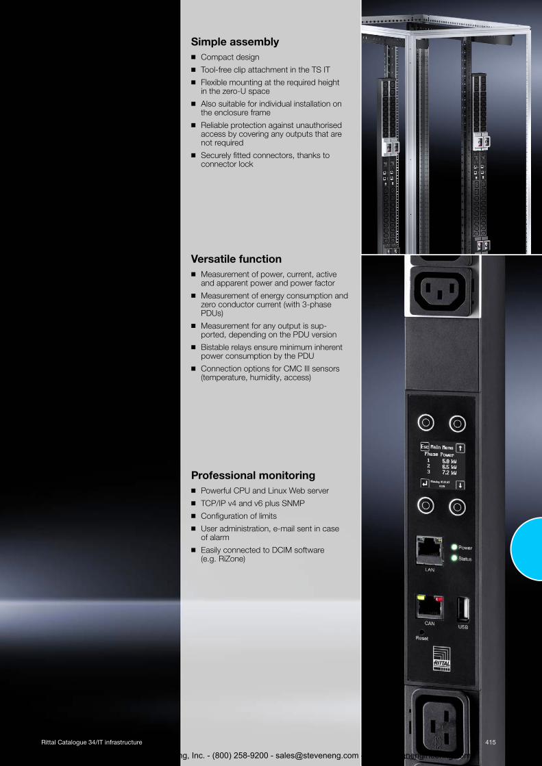
Simple assembly◾ Compact design
◾ Tool-free clip attachment in the TS IT
◾ Flexible mounting at the required height in the zero-U space
◾ Also suitable for individual installation on the enclosure frame
◾ Reliable protection against unauthorised access by covering any outputs that are not required
◾ Securely fitted connectors, thanks to connector lock
Versatile function◾ Measurement of power, current, active
and apparent power and power factor
◾ Measurement of energy consumption and zero conductor current (with 3-phase PDUs)
◾ Measurement for any output is sup-ported, depending on the PDU version
◾ Bistable relays ensure minimum inherent power consumption by the PDU
◾ Connection options for CMC III sensors (temperature, humidity, access)
Professional monitoring◾ Powerful CPU and Linux Web server
◾ TCP/IP v4 and v6 plus SNMP
◾ Configuration of limits
◾ User administration, e-mail sent in case of alarm
◾ Easily connected to DCIM software (e.g. RiZone)
415
, Inc. - (800) 258-9200 - [email protected] - www.stevenengineering.com

ower Distribution Unit
PC
Be◾
◾
◾◾◾
◾
onfiguration Page 419
nefits: With the compact PDU, any IT rack may be easily equipped with a professional power dis-tribution system With the TS IT rack, assembly is even tool-freeCompact designEasy to assemblePower-saving design, minimal inherent consumption by the PDU itself, thanks to the use of bistable relays and OLED display with power-saving functionIntegral Web server for direct network connection with extensive user administration (not PDU basic/slave PDU)
◾ Redundant power supply from all 3 phases and additionally via an existing PoE (Power over Ethernet) network
◾ Extensive range of manage-ment and monitoring functions
◾ High-MTBF and measurement accuracy of 1%
◾ CAN bus for connecting slave PDUs (not PDU basic)
◾ Ambient monitoring with up to 4 CMC III sensors (tempera-ture, humidity, access, vandal-ism)
PDU design variants:PDU basic Robust, compact basic power distributor for the IT environment
PDU metered Energy measurement per phase, i.e. output requirement of an entire IT rack
PDU switched Measurement function per phase and individually switchable output slots
PDU managed High-end IT rack, power distribu-tion with energy measurement and monitoring functions for each individual output slot
Material: – Extruded aluminium section,
anodised
Protection category IP to IEC 60 529: – IP 20
Standards: – EN 60 950– EN 61 000-4– EN 61 000-6– EN 55 022
Safety directive:– 2006/95/EC
EMC directive:– 2004/108/EC
Photo shows a configuration example with equipment not included in the scope of supply
PDU international, basic version Power Pin patterns Dimensions
Model No.No. of phases Phase current
A Input Outputs C13 Outputs C19 PDU length mm
Minimum enclosure height
mm1 16 CEE 24 4 970 1200 7955.1101 32 CEE 24 4 1115 1400 7955.1113 16 CEE 18 3 845 1200 7955.1313 16 CEE 24 6 1145 1400 7955.1323 32 CEE 24 6 1365 1800 7955.1333 32 CEE 36 6 1710 2000 7955.1343 16 CEE 42 – 1405 1800 7955.135
416 Rittal Catalogue 34/IT infrastructure
Courtesy of Steven Engineering, Inc. - (800) 258-9200 - [email protected] - www.stevenengineering.com

Power Distribution Unit
PDU international, metered versionPDU international, switched version
PDU international, managed version
Slave PDU international, managed version
Power Pin patterns Dimensions
Model No.No. of phases Phase current
A Input Outputs C13 Outputs C19 PDU length mm
Minimum enclosure height
mm1 16 C20 12 – 710 800 7955.2011 16 CEE 24 4 1225 1400 7955.2101 32 CEE 24 4 1370 1800 7955.2113 16 CEE 18 3 1100 1400 7955.2313 16 CEE 24 6 1395 1800 7955.2323 32 CEE 24 6 1620 2000 7955.2333 32 CEE 36 6 1960 2200 7955.2343 16 CEE 42 – 1665 2000 7955.2353 32 CEE 48 – 2050 2200 7955.2363 63 CEE 12 12 482.6 mm (19˝) / 3 U 1200 7955.238
Power Pin patterns Dimensions
Model No.No. of phases Phase current
A Input Outputs C13 Outputs C19 PDU length mm
Minimum enclosure height
mm1 16 C20 12 – 710 800 7955.3011 16 CEE 24 4 1225 1400 7955.3101 32 CEE 24 4 1370 1800 7955.3113 16 CEE 18 3 1100 1400 7955.3313 16 CEE 24 6 1395 1800 7955.3323 32 CEE 24 6 1620 2000 7955.3333 32 CEE 36 6 1960 2200 7955.3343 16 CEE 42 – 1665 2000 7955.3353 32 CEE 48 – 2050 2200 7955.336
Power Pin patterns Dimensions
Model No.No. of phases Phase current
A Input Outputs C13 Outputs C19 PDU length mm
Minimum enclosure height
mm1 16 C20 12 – 710 800 7955.4011 16 CEE 24 4 1225 1400 7955.4101 32 CEE 24 4 1370 1800 7955.4113 16 CEE 18 3 1100 1400 7955.4313 16 CEE 24 6 1395 1800 7955.4323 32 CEE 24 6 1620 2000 7955.4333 32 CEE 36 6 1960 2200 7955.4343 16 CEE 42 – 1665 2000 7955.4353 32 CEE 48 – 2050 2200 7955.436
Power Pin patterns Dimensions
Model No.No. of phases Phase current
A Input Outputs C13 Outputs C19 PDU length mm
Minimum enclosure height
mm1 16 C20 12 – 710 800 7955.9011 16 CEE 24 4 1225 1400 7955.9101 32 CEE 24 4 1370 1800 7955.9113 16 CEE 18 3 1100 1400 7955.9313 16 CEE 24 6 1395 1800 7955.9323 32 CEE 24 6 1620 2000 7955.933
417Rittal Catalogue 34/IT infrastructure
Courtesy of Steven Engineering, Inc. - (800) 258-9200 - [email protected] - www.stevenengineering.com

Power Distribution Unit
PDU UK, basic versionPDU UK, metered version
PDU UK, switched version
PDU UK, managed version
Slave PDU UK, managed version
PDU accessories
CMC III sensors (max. 4 sensors per PDU)
Power Pin patterns Dimensions
Model No.No. of phases Phase current
A Input Outputs UK connector Outputs C19 PDU length
mm
Minimum enclosure height
mm1 13 UK 6 – 440 600 7955.5101 13 UK 8 – 535 800 7955.5111 13 UK 10 – 640 800 7955.5121 13 UK 12 – 745 1000 7955.513
Power Pin patterns Dimensions
Model No.No. of phases Phase current
A Input Outputs UK connector Outputs C19 PDU length
mm
Minimum enclosure height
mm1 13 UK 16 – 1210 1400 7955.5201 16 CEE 20 4 1695 2000 7955.5211 32 CEE 20 4 1955 2200 7955.522
Power Pin patterns Dimensions
Model No.No. of phases Phase current
A Input Outputs UK connector Outputs C19 PDU length
mm
Minimum enclosure height
mm1 13 UK 16 – 1210 1400 7955.5301 16 CEE 16 4 1380 1800 7955.5311 32 CEE 16 4 1520 1800 7955.532
Power Pin patterns Dimensions
Model No.No. of phases Phase current
A Input Outputs UK connector Outputs C19 PDU length
mm
Minimum enclosure height
mm1 13 UK 16 – 1210 1400 7955.5401 16 CEE 16 4 1380 1800 7955.5411 32 CEE 16 4 1525 1800 7955.542
Power Pin patterns Dimensions
Model No.No. of phases Phase current
A Input Outputs UK connector Outputs C19 PDU length
mm
Minimum enclosure height
mm1 13 UK 16 – 1210 1400 7955.9401 16 CEE 16 4 1380 1800 7955.9411 32 CEE 16 4 1525 1800 7955.942
Packs of Model No. PageCovers for C13 slot, lockable 10 pc(s). 7955.010Covers for C19 slot, lockable 10 pc(s). 7955.015Connector, universal lock for C14/C20 connector 20 pc(s). 7955.020Connection cable D/C19, 1.8 m 1 pc(s). 7200.216 457 Connection cable C19/C20, 1.8 m 1 pc(s). 7200.217 457
CMC III/PDU sensor type Packs of Model No. PageTemperature sensor 1 pc(s). 7030.110 454 Temperature/humidity sensor (combi-sensor) 1 pc(s). 7030.111 454 Infrared access sensor 1 pc(s). 7030.120 454 Vandalism sensor 1 pc(s). 7030.130 454 CMC III CAN bus connection cable RJ 45, length 0.5 – 10 m 1 pc(s). see page 457
418 Rittal Catalogue 34/IT infrastructure
Courtesy of Steven Engineering, Inc. - (800) 258-9200 - [email protected] - www.stevenengineering.com

Power Distribution Unit
ConfigurationPDU versionmanaged/managed
slave1)switched metered basic
MechanicalMay be fitted in the zero-U space in the 600 mm wide TS IT, tool-free ◾ ◾ ◾ ◾Colour coding of phases and fuse circuits (depending on PDU version) ◾ ◾ ◾ ◾Connection cable, static, 3 m, with CEE connector (IEC 60 309) or C20 ◾ ◾ ◾ ◾Connector lock for C13 and C19 pin patterns (optional) ◾ ◾ ◾ ◾Lockable cover for slots that are not needed (for C13/C19) ◾ ◾ – – PDU slave version without display and Ethernet connection for use with PDU master and CMC III ◾ – – – ElectricalPower supply 110 V – 230 V/400 V, inherent power consumption approx. 15 W ◾ ◾ ◾ – Rated current 16/32 A, single-phase/3-phase ◾ ◾ ◾ ◾Version additionally 63 A/3-phase (blade PDU, no Zero-U) – – ◾ – Electromagnetic circuit-breaker, 16 A, type C (only with 32/63 A PDU versions) ◾ ◾ ◾ ◾PDU self-supplied, no external power supply required ◾ ◾ ◾ – PDU power supply redundant across all phases (with 3-phase PDUs) ◾ ◾ ◾ – Emergency power supply to PDU web server via PoE (Power over Ethernet), remains accessible even in the event of a mains failure ◾ ◾ – –
Switching function per output slot ◾ ◾ – – Sequential activation of the outputs once the power is resumed (avoids overload peaks) ◾ ◾ – – Switching states are saved even in the event of a power failure ◾ ◾ – – Bistable relays/minimal power consumption ◾ ◾ – – Grouping (joint switching of several outputs) ◾ ◾ – – Measurement functionsVoltage (V), current (A), frequency (Hz) ◾ ◾ ◾ – Active power (kW), active energy (kWh), apparent power (kVA), apparent energy (kVAh) ◾ ◾ ◾ – Power factor (cos phi) ◾ ◾ ◾ – Zero conductor measurement/load imbalance detection ◾ ◾ ◾ – Fuse monitoring (with 32/63 A versions) ◾ ◾ ◾ – Measurement per phase or infeed – ◾ ◾ – Measurement per output slot ◾ – – – Measurement accuracy +/-1% (kWh) to IEC 50 430-1 ◾ ◾ ◾ – Connectivity/management functionsPowerful 400 MHz CPU and Linux operating system (not with slave versions) ◾ ◾ ◾ – Graphic OLED display 128 x 128 pixels (RGB) with back-lighting and energy-saving mode (display of output data and basic IP configuration) ◾ ◾ ◾ –
Position sensor for display rotation (and correct visualisation in the DCIM software RiZone) ◾ ◾ ◾ – Multi-colour LEDs (green/red) to indicate switching states and limits per phase or infeed – ◾ – – Multi-colour LEDs (green/red) to indicate switching states and limits per individual output slot ◾ – – – Settable limits (warning/alarm) ◾ ◾ ◾ – Operating hours meter, total and cyclical (resettable) ◾ ◾ ◾ – Ethernet connection (RJ 45) ◾ ◾ ◾ – USB A-port for firmware update and data logging functions ◾ ◾ ◾ – CAN bus interface (RJ 45) ◾ ◾ ◾ – Web server (HTTP, HTTPS, SSL, SSH) NTP, Telnet ◾ ◾ ◾ – TCP/IP v4 and v6, DHCP ◾ ◾ ◾ – SNMP v1, v2c and v3 ◾ ◾ ◾ – FTP/SFTP (update/file transfer) ◾ ◾ ◾ – E-mail forwarding in case of alarm (SMTP) ◾ ◾ ◾ – User administration including rights management ◾ ◾ ◾ – LDAP(S)/Radius/Active Directory connection ◾ ◾ ◾ – Syslog server connection (max. 4 servers) ◾ ◾ ◾ – Plug & play drivers in the Rittal RiZone DCIM software ◾ ◾ ◾ – MIB for linking into 3rd party software ◾ ◾ ◾ – Suitable for connection to Rittal CMC III system ◾ ◾ ◾ – CMC III CAN bus sensors may be connected for ambient monitoring (max. 4 sensors) ◾ ◾ ◾ – CMC III sensors that may be used: Temperature sensor, temperature/humidity sensor, infrared access sensor, vandalism sensor ◾ ◾ ◾ –
Ambient conditionsOperating temperature 0°C...+45°C 0°C...+45°C 0°C...+45°C 0°C...+45°CStorage temperature -25°C...+70°C -25°C...+70°C -25°C...+70°C -25°C...+70°C Ambient humidity % (non-condensing) 10 – 95 10 – 95 10 – 95 10 – 95Protection category IP to IEC 60 529 IP 20 IP 20 IP 20 IP 20
1) Managed slave without display/network
419Rittal Catalogue 34/IT infrastructure
Courtesy of Steven Engineering, Inc. - (800) 258-9200 - [email protected] - www.stevenengineering.com

Power Distribution Unit
Sample applicationsMaster/slave principle Up to 3 slave PDUs may be connected to one PDU.Connection of CAN bus sensorsAdditionally, up to 4 CMC III CAN bus sensors may be connected to the PDU master for ambient monitoring (temperature, humidity, access).
Up to 4 CAN bus com-ponents supported
managed slave (without display)
PDU metered master PDU switched master PDU managed master
IP network
PDU metered master PDU switched master PDU managed master
IP network
PDU metered master PDU switched master PDU managed master
PDU managed slave (without display/network)
CMC III
CMC III sensors
CAN
Configuration example of a redundant network infrastructure Monitoring via 2 separate networks. The leading system is configurable.
420
Courtesy o
f Steven Engineering, Inc. - (800) 258-92Rittal Cata
00 - [email protected] - www.stevenengine
logue 34/IT infrastructure
ering.com

Power System Module
C
Fotio161 mThththcotiomacthinMIn
MC III monitoring system Page 446
r upgrading existing installa-ns or for measuring individual A/32 A equipment, the PSM
U MID measurement modules ay be used. ese are readily integrated into e 482.6 mm (19˝) level or into e zero-U space of the rack, and nnected using suitable connec-n cables. These measurement odules have an MID-compliant tive energy meter and are erefore suitable for energy bill-g purposes. ID stands for “Measurement struments Directive” and regu-
lates 10 types of measurement equipment based on EU Directive 2004/22/EC. MID-approved equipment is authorised for use throughout the EU.
Benefits: ◾ For 16 A and 32 A phase
current◾ Easy to assemble◾ Billable MID measurement units◾ CAN bus for connection to
CMC III system◾ Extensive management
and monitoring functions (via CMC III)
◾ High-MTBF and measurement accuracy of +/-1%
◾ Energy-efficient electric design – minimal inherent power con-sumption
◾ 1 U, 482.6 mm (19˝) sheet steel enclosure, for flexible mounting
Measurement functions: – Voltage (V), current (A),
frequency (Hz)– Active power (kW), active
energy (kWh), apparent power (kVA), apparent energy (kVAh)
– Power factor (cos phi) – Zero conductor measurement/
load imbalance detection– Measurement per phase or
infeed– Measurement accuracy +/-1%
(kWh) to IEC 50 430-1– MID certification of the active
energy meter, suitable for energy billing purposes
Material: – Enclosure: Sheet steel
Colour:– RAL 9005
Protection category IPto IEC 60 529:– IP 51
Standards: – EN 60 950– EN 61 000-6-1– EN 61 000-6-2– EN 55 022
Safety directive: – 2006/95/EC
EMC directive:– 2004/108/EC
Photo shows a configuration example with equipment not included in the scope of supply
MID measurement module for CMC III Model No. 7859.312 7859.332Version 16 A 32 A Sheet steel enclosure 1 U for 482.6 mm (19˝) mounting, approx. 200 mm deep ◾ ◾Assembly parts ◾ ◾Connection cable, plug-in, various versions ◾ ◾Input voltage 230 V/400 V (50/60 Hz) ◾ ◾No. of infeeds (each 3-phase) 2 2Rated current A (per phase) 16 32 Power supply across all 3 phases (internal power pack) ◾ ◾Maximum no. of systems that may be connected to one CMC-PU III 8 8Ambient conditionsOperating temperature -25°C…+55°C -25°C…+55°CStorage temperature -25°C…+70°C -25°C…+70°CAmbient humidity % (non-condensing) 10 – 95 10 – 95 AccessoriesConnection cables, set: 1 x input 2 m/1 x output 2 m CEE (IEC 60 309, jack)(2 x required when using both infeeds) 7859.315 7859.335
Connection cables for PSM busbars: Input cable 3 m/output cable 1.2 m (with Wago X-COM connector)(2 x required when using both infeeds) 7859.316 –
421Rittal Catalogue 34/IT infrastructure
Courtesy of Steven Engineering, Inc. - (800) 258-9200 - [email protected] - www.stevenengineering.com

422
1
2
3
4
5
6
Courtesy of Steven En
Power supply
Socket stripsRittal Catalogue 34/IT infrastructure
Socket strips in an aluminium duct The socket strips in the aluminium duct are avail-able in various lengths with different functional ele-ments. Special attention has been devoted to prac-tical, universal fastening: Variable attachment facilities have been created with an angle bracket which may be inserted in four posi-tions. Hence, for example, the 482 mm long socket strip may optionally be mounted on 482.6 mm (19˝) mounting angles, the 482.6 mm (19˝) mounting frame, the enclosure frame, or in the rear section of the wall-mounted distributor. Without additional mounting accessories, the socket strip may be inserted into all sections with a 25 mm pitch pat-tern. This makes selection much easier, as well as providing additional flexibility and saving on ware-housing. Provision has also been made for cable routing of the infeed, and when mounting in the 482.6 mm (19˝) section there is adequate space to route the infeed between the socket strip and the mounting angle without kinks. The arrangement of the IEC 320 sockets at a 45° angle allows unrestricted use of angular connectors.
Technical specifications: Earthing-pin socket strips:– Connector type F (CEE 7/4)– Rated operating voltage: 250 V – Connection cable: 2 m long H05VV-F3G1.5
without connector, � with connector
Belgium/France (B/F) socket strips:– Connector type E (CEE 7/5) – Rated operating voltage: 250 V – Connection cable: 2 m long H05VV-F3G1.5
with wire end ferrules
Equipment connector strips (IEC 60 320-1/C13) Socket strips:– Rated operating voltage: 250 V – Connector input: C14 or cable H05VV-F3G1.0,
depending on the version
Material: – Aluminium section: Natural anodised – Socket inserts: Polycarbonate
Supply includes: – Socket strip – Two mounting brackets – Assembly parts
Standards: – Earthing-pin socket: DIN 49 440 – IEC 320 socket: EN 60 320-2-2– Overvoltage protection: DIN EN 61 643-11
(VDE 0675 Part 6-11)
Approvals: – CE – RoHS
Note: – Depending on the application, we recommend
use of a charging current reserve to prevent incorrect activation due to starting-current spikes
Technical details: Available on the Internet
31.7544
T2T1
44
Connector type earthing-pin
Connector type C13
VersionRated current
A
Con-nection
No. of sockets
Attachment Length
(T1) mm
Mounting dimen-
sion (T2) mm1)
Model No.Frame
Wall-mounted
distributor, horizontal
482.6 mm (19˝) level
� Without rocker switch 16 Cable 3 ◾ – – 262.6 232.5 7240.1107 ◾ ◾ ◾ 482.6 452.5 7240.21012 ◾ – – 658.6 628.5 7240.310
� With rocker switch 16 Cable 3 ◾ ◾ – 306.6 276.5 7240.1207 ◾ ◾ ◾ 482.6 452.5 7240.220
� Overvoltage protection, type 3 and interference suppressor filter
16 Cable 5 ◾ ◾ ◾ 482.6 452.5 7240.230
9 ◾ – – 658.6 628.5 7240.330
� Circuit-breaker, type B, 16 A, 2-pole 16 Cable 5 ◾ ◾ ◾ 482.6 452.5 7240.240
� UPS strip, connection cable with 10 A IEC 320 connector type E, with 10 A G-fuse
10 C14 7 ◾ ◾ ◾ 482.6 452.5 7240.260
FI switch, 0.03 A, 2-pole, type A 16 Cable 5 ◾ ◾ ◾ 482.6 452.5 7240.280
B/F sockets, type E with earthing pin (Belgium/France) 16 Cable 7 ◾ ◾ ◾ 482.6 452.5 7240.510
1) Variable attachment distance within a range of 25 mm, the dimension given is hole centre – hole centre of the mounting bracket
VersionRated current
A
Con-nection
No. of sockets
Attachment Length
(T1) mm
Mountingdimen-
sion (T2) mm1)
Model No.Frame
Wall-mounted
distributor, horizontal
482.6 mm (19˝) level
For IEC 320 connectors 10 Cable 12 ◾ ◾ ◾ 482.6 452.5 7240.200For IEC 320 connectors with IEC 320 input 10 C14 9 ◾ ◾ ◾ 482.6 452.5 7240.201
1) Variable attachment distance within a range of 25 mm, the dimension given is hole centre – hole centre of the mounting bracket
gineering, Inc. - (800) 258-9200 - [email protected] - www.stevenengineering.com

Power supply
423
tevenengineering.com
Socket strips
Rittal Catalogue 34/IT infrastructure
Socket strip Earthing-pin, with plastic housing Robust 8-way earthing-pin socket strip in a plastic housing. The strip may be mounted vertically on the enclosure frame or in the 482.6 mm (19˝) section. 2.5 U are required for 482.6 mm (19˝) installation. The earthing-pin inserts are arranged at an angle of 45° so that angular connectors are also easily used. The connection cable is attached to a terminal con-nection (behind a removable cover) in the socket strip. The socket strip has a terminal for an external earthing connection.
Technical specifications: – Connector type F (CEE 7/4)– Rated operating voltage: 230 V – Rated current: 16 A– Connection cable: Type H05VV-F3G1.5 (black)
with wire end ferrules – Length: 2 m – Dimensions:
W x H x D: 483 x 74 x 45 mm
Supply includes: – 1 socket strip – Assembly parts
Material: – Plastic (grey/black)
Approvals: – CE – RoHS
Socket strip Model No.8-way, earthing-pin 7000.630
Socket strip Earthing-pin, with ammeter The socket strip with ammeter measures the active power of the connected equipment. The 482.6 mm (19˝) long socket strip may optionally be mounted on the 482.6 mm (19˝) mounting angles, on the 482.6 mm (19˝) mounting frame, on the enclosure frame or in the rear section of wall-mounted distribu-tors. The installation bracket may be mounted in four different positions for variable mounting. With-out additional mounting accessories, the socket strip may be inserted into all sections with a 25 mm pitch pattern.
Technical specifications: – Rated operating voltage: 250 V – Rated current: 16 A– Connection cable: Type H05VV-F3G1.5 (black)
with wire end ferrules – Length: 3 m– Dimensions:
W x H x D: 480 x 45 x 50 mm
Material: – Aluminium section: Natural anodised– Socket inserts: Polycarbonate
Display colour: – Blue, luminescent
Supply includes: – 1 socket strip – 2 installation brackets – Assembly parts– 3 m connection cable with wire end ferrules
Approvals: – CE – RoHS
Version No. of sockets
AttachmentLength
mm
Mounting dimensions
mm1) Model No.
FrameWall-mounted
distributor, horizontal
482.6 mm (19˝) level
IEC 320/CEE 7/4 7 ◾ ◾ ◾ 482.6 464.1 7240.3001) Variable attachment distance within a range of 25 mm, the dimension given is hole centre – hole centre
of the mounting bracket
Courtesy of Steven Engineering, Inc. - (800) 258-9200 - [email protected] - www.s

Power supply
424
Courtesy of Steven En
Socket strips
Rittal Catalogue 34/IT infrastructure
Junction box with multi-functional bracketThe angle bracket can be installed in all network enclosures in a system-compatible design. The junction box serves as a transfer point for the power supply to all equipment (fans, lights and socket strips). As well as being used as a junction box or transfer point, the bracket can also accommodate the enclosure internal thermostat 3110.000 or the hygrostat 3118.000, due to its integral holes.
Material: – Sheet steel
Colour: – RAL 7035
Supply includes: – 1 junction box– 1 bracket– 6 m connection cable 3 x 1.5 mm2 (flexible)
Packs of Model No.1 set(s) 7280.035
Socket◾ For mounting on support rails TS 35/7.5 and
TS 35/15 to EN 60 715 ◾ Uniform screw terminals from one side◾ Enclosure width 45 mm
Technical specifications: – Rated voltage: 250 V – Rated current: 16 A
Material: – Polyamide
Colour: – Grey
Standards: – DIN VDE 0620-1– DIN 49 440-1
Version Packs of Model No.Earthing-pin/CEE 7/4 2 pc(s). 2506.100
Service socketfor enclosure frame attachment/16 A Integration of a service socket within a separate supply circuit, independently of the IT network and UPS. Simple installation via an angle bracket for attaching to the enclosure frame.
Type: Earthing contact/CEE 7/4
Material: – Angle bracket: Sheet steel – Socket: Plastic
Surface finish: – Angle bracket: Zinc-plated
Supply includes: – 1 angle bracket– 1 damp-proof socket (IP 44) – Assembly parts
Packs of Model No.1 set(s) 7280.100
gineering, Inc. - (800) 258-9200 - [email protected] - www.stevenengineering.com
Power supply
425
tevenengineering.com
Socket strips
Rittal Catalogue 34/IT infrastructure
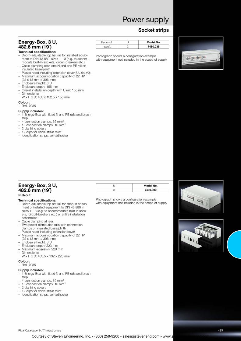
Energy-Box, 3 U, 482.6 mm (19˝)Technical specifications: – Depth-adjustable top hat rail for installed equip-
ment to DIN 43 880, sizes 1 – 3 (e.g. to accom-modate built-in sockets, circuit-breakers etc.).
– Cable clamping rear, one N and one PE rail on insulated base/plinth
– Plastic hood including extension cover (UL 94-V0) – Maximum accommodation capacity of 22 HP
(22 x 18 mm = 396 mm) – Enclosure height: 3 U– Enclosure depth: 155 mm – Overall installation depth with C rail: 155 mm – Dimensions:
W x H x D: 483 x 132.5 x 155 mm
Colour: – RAL 7035
Supply includes: – 1 Energy-Box with fitted N and PE rails and brush
strip – 4 connection clamps, 35 mm2 – 18 connection clamps, 16 mm2 – 2 blanking covers– 12 clips for cable strain relief– Identification strips, self-adhesive
Photograph shows a configuration example with equipment not included in the scope of supply
Packs of U Model No.1 pc(s). 3 7480.035
Energy-Box, 3 U, 482.6 mm (19˝) Pull-out
Technical specifications: – Depth-adjustable top hat rail for snap-in attach-
ment of installed equipment to DIN 43 880 in sizes 1 – 3 (e.g. to accommodate built-in sock-ets, circuit-breakers etc.) or entire installation assemblies
– Cable clamping at rear – Two power distribution rails with connection
clamps on insulated base/plinth – Plastic hood including extension cover – Maximum accommodation capacity of 22 HP
(22 x 18 mm = 396 mm) – Enclosure height: 3 U– Enclosure depth: 223 mm – Maximum extension: 220 mm – Dimensions:
W x H x D: 483.5 x 132 x 223 mm
Colour: – RAL 7035
Supply includes: – 1 Energy-Box with fitted N and PE rails and brush
strip – 4 connection clamps, 35 mm2 – 18 connection clamps, 16 mm2 – 2 blanking covers– 12 clips for cable strain relief– Identification strips, self-adhesive
Photograph shows a configuration example with equipment not included in the scope of supply
U Model No.3 7480.300
Courtesy of Steven Engineering, Inc. - (800) 258-9200 - [email protected] - www.s

426 Rittal Catalogue 34/IT infrastructure
2
2
2
2
3
3
4
6
6
5
Courtesy of Steven Engineering, Inc. - (800) 258-9200 - [email protected] - www.stevenengineering.com

Rittal Catalogue 34/IT infrastructure
1
Courtesy of Steven Engineering, Inc. - (800) 2
IT cooling
Liquid Cooling PackageLCP Rack CW ............................................................................................428LCP Inline CW ............................................................................................429LCP T3+ CW..............................................................................................430LCP Rack DX .............................................................................................431LCP Inline DX..............................................................................................432Accessories for LCP CW/DX.......................................................................433
Aisle containmentAisle containment .......................................................................................435
Roof-mounted cooling unitsFor cooling IT equipment ............................................................................436
Small cooling unitsRoof-mounted fans.....................................................................................437Fan mounting plate for TS IT.......................................................................437Fan mounting plate.....................................................................................438Fan expansion kit........................................................................................438Fan cross member......................................................................................439Fan expansion kit for fan cross member .....................................................439Vent cover ..................................................................................................440
Chillers for IT coolingOverall cooling output 15 – 481 kW ............................................................441
Your benefits◾ State-of-the-art climate control technology, from cooling single racks
to complete data centres◾ Individual climate control concepts for rack, suite and room cooling◾ Enhanced security plus superior energy and cost efficiency◾ Optimisation with aisle containment and cross-system control concepts◾ Energy-efficient cooling with IT chillers◾ Minimisation of operating costs with free cooling◾ Environmentally friendly, thanks to resource and CO2 savings◾ Planning, assembly, commissioning and servicing – all from a single
supplier!
Sample applications� Aisle containment, see page 435
� Liquid Cooling Package LCP, see page 428
� IT chiller with integral free cooling, see page 441
� Pipework
� Raised floor for cold air supply
CRAC system (partner product)
Please note:Rittal no longer sells its own CRAC systems; instead, from now on, we are collaborating with a few selected product partners and recommending them for use in system solutions and IT projects.
5
The advantages for our customers are as follows: ◾ Independent selection of the best CRAC systems from a technical and
financial perspective, depending on the technical requirements and regional framework conditions
◾ Clear regulation of the customer/supplier relationship in terms of procurement, installation, commissioning and services
◾ Clear regulation of warranties and product liability
For our chosen product partners, Rittal provides key basic information (such as technical properties, ordering instructions, contact addresses and other details, where applicable). Further details can be found on our website at www.rittal.com.
427
8-9200 - [email protected] - www.stevenengineering.com

Liquid Cooling Package
Accessories for LCP Page 433 Chillers for IT cooling Page 441 Network/server enclosures TS IT Page 92
Benefits:– Maximum energy efficiency
thanks to EC fan technology and IT-based control
– Minimal pressure loss at the air end, which in turn minimises the power consumption of the fans
– Control of the server inlet tem-perature
– With redundant temperature sensor integrated at the air end as standard
– Optimum adaptability thanks to
– Targeted cooling output thanks to modular fan units
– Fan modules configurable as n+1 redundancy
– Standard 3-phase connection for electrical redundancy
– The separation of cooling and rack prevents water from entering the server enclosure
– Up to 55 kW cooling output on a footprint of just 0.36 m²
– Minimal area load due to low weight
Functions:The LCP draws in the air at the sides at the rear of the server enclosures, cools it using high-performance compact impellers, and blows the cooled air back into the front part of the server enclosure at the sides
Monitoring:– Monitoring of all system-rele-
vant parameters such as server air intake temperature, server waste air temperature, water inlet/return temperature, water
Colour:– RAL 7035
Protection category IP to IEC 60 529:– IP 20
Cooling medium:– Water
Optional:– Fully integrated fire detection
and extinguisher system – Automatic server enclosure
door opening– Various sensors
dynamic, continuous control ofthe cold water volume flow– By using high water inlet tem-
peratures, the proportion of indirect free cooling is increased, which in turn reduces operating costs
flow, cooling output, fan speed, leakage
– Direct connection of the unit via SNMP over Ethernet
Temperature control:– Linear fan control– Two-way control valve
– Racks 2200 mm high
Technical details:Available on the Internet
Photo shows a configuration example with equipment not included in the scope of supply
LCP Rack CWModel No. Packs of 3311.130 3311.230 3311.260 Page
Total cooling output/Number of fan modules required kW
10 / 120 / 230 / 3
10 / 120 / 230 / 3
40 / 445 / 555 / 6
Number of fan modules in supplied state 1 1 4Width mm 300 300 300Height mm 2000 2000 2000Depth mm 1000 1200 1200Installation in bayed enclosure suite Flush Flush Flush
Rated operating voltage V, ~, Hz 230, 1~, 50/60400, 3~, 50/60
230, 1~, 50/60400, 3~, 50/60
230, 1~, 50/60400, 3~, 50/60
Type of electrical connection Connector Connector ConnectorAir throughput at max. cooling output m³/h 4800 4800 8000Fans may be exchanged with the system operational ◾ ◾ ◾EC fan ◾ ◾ ◾Water inlet temperature °C 15 15 15Permissible operating pressure (p. max.) bar 6 6 6Duty cycle % 100 100 100Water connection 1½" external thread 1½" external thread 1½" external threadWeight as delivered kg 214.0 214.0 235.0AccessoriesFan module 1 pc(s). 3311.011 3311.011 3311.011 434
428 Rittal Catalogue 34/IT infrastructure
Touchscreen display, colour 1 pc(s). 3311.030 3311.030 3311.030 433Connection hose, bottom and top 2 pc(s). 3311.040 3311.040 3311.040 433
Courtesy of Steven Engineering, Inc. - (800) 258-9200 - [email protected] - www.stevenengineering.com

Liquid Cooling Package
429Rittal Catalogue 34/IT infrastructure
Accessories for LCP Page 433 Chillers for IT cooling Page 441 Network/server enclosures TS IT Page 92
Benefits:– Maximum energy efficiency
thanks to EC fan technology and IT-based control
– Minimal pressure loss at the air end, which in turn minimises the power consumption of the fans
– Optimum adaptability due to dynamic, continuous control of the cold water volume flow
– By using high water inlet tem-peratures, the proportion of indirect free cooling is increased, which in turn reduces operating costs
– Targeted cooling output thanks to modular fan units
– Fan modules configurable as n+1 redundancy
– Standard 3-phase connection for electrical redundancy
– With redundant temperature sensor integrated at the air end as standard
– The separation of cooling and rack prevents the ingress of water into the server enclosure
– Up to 55 kW cooling output on a footprint of just 0.36 m²
– Minimal area load due to low weight
Functions:The hot air is drawn in from the room or hot aisle at the rear of the device and expelled at the front into the cold aisle after cooling. The LCP achieves maximum per-formance and efficiency in con-junction with Rittal cold aisle con-tainment. With this product, a raised floor is not necessary.
Monitoring:– Monitoring of all system-rele-
vant parameters such as server air intake temperature, server waste air temperature, water inlet/return temperature, water flow, cooling output, fan speed, leakage
– Direct connection of the unit via SNMP over Ethernet
– Integration into RiZone
Temperature control:– Linear fan control– Two-way control valve
Colour:– RAL 7035
Protection category IP to IEC 60 529:– IP 20
Cooling medium:– Water
Optional:– Various sensors– Racks 2200 mm high
Technical details:Available on the Internet
Photo shows a configuration example with equipment not included in the scope of supply
LCP Inline CWModel No. Packs of 3311.530 3311.540 3311.560 Page
Total cooling output/Number of fan modules required kW
10 / 120 / 230 / 3
18 / 227 / 330 / 4
40 / 445 / 555 / 6
Number of fan modules in supplied state 1 2 4Width mm 300 300 300Height mm 2000 2000 2000Depth mm 1200 1200 1200Installation in bayed enclosure suite Set forward Flush Set forward
Rated operating voltage V, ~, Hz 230, 1~, 50/60400, 3~, 50/60
230, 1~, 50/60400, 3~, 50/60
230, 1~, 50/60400, 3~, 50/60
Type of electrical connection Connector Connector ConnectorAir throughput at max. cooling output m³/h 4800 4800 8000Fans may be exchanged with the system operational ◾ ◾ ◾EC fan ◾ ◾ ◾Permissible operating pressure (p. max.) bar 6 6 6Duty cycle % 100 100 100Water connection 1½" external thread 1½" external thread 1½" external threadWater inlet temperature °C 15 15 15Weight as delivered kg 214.0 221.0 235.0AccessoriesFan module 1 pc(s). 3311.011 3311.011 3311.011 434Touchscreen display, colour 1 pc(s). 3311.030 3311.030 3311.030 433Connection hose, bottom and top 2 pc(s). 3311.040 3311.040 3311.040 433Rear adaptor 1 pc(s). 3311.080 – 3311.080 433
Courtesy of Steven Engineering, Inc. - (800) 258-9200 - [email protected] - www.stevenengineering.com

Liquid Cooling Package
Accessories for LCP Page 433 Chillers for IT cooling Page 441 Network/server enclosures TS IT Page 92
Benefits:– Error-tolerant, efficient cooling
of server racks with high ther-mal loads
– Fully redundant – two active cooling circuits and two switch-able power circuits ensure opti-mum fail-safeness
– The built-in controllers are capable of adapting all device parameters automatically to preserve the required cooling outputs
– A separate decentralised intelli-
– Interfaces which facilitate user-friendly operation and monitor-ing via the network or BSM systems
Functions:The LCP draws in the air at the sides at the rear of the server enclosures, cools it using high-performance compact impellers, and blows the cooled air back into the front part of the server enclosure at the sides
Monitoring:– Monitoring of all system-rele-
vant parameters such as server air intake temperature, server waste air temperature, water inlet/return temperature, water
Temperature control:– Linear fan control– Two-way control valve
Colour:– RAL 7035
Protection category IP to IEC 60 529:– IP 20
Cooling medium:– Water
Optional:– Fully integrated fire detection
gence which automatically rec-ognises emergency situations and responds appropriately with the "auto-load balancing" and "auto-recovery" functions
flow, cooling output, fan speed, leakage
and extinguisher system – Automatic server enclosure
door opening– Various sensors
Photo shows a configuration example with equipment not included in the scope of supply
LCP T3+ CWModel No. 3300.239 PageTotal cooling output kW 20Width mm 300Height mm 2200Depth mm 1200Rated operating voltage V, ~, Hz 230, 1~, 50/60Type of electrical connection C19/C20Fans may be exchanged with the system operational ◾EC fan ◾Duty cycle % 100Weight as delivered kg 215.0
430 Rittal Catalogue 34/IT infrastructure
Courtesy of Steven Engineering, Inc. - (800) 258-9200 - [email protected] - www.stevenengineering.com

Liquid Cooling Package
431Rittal Catalogue 34/IT infrastructure
Accessories for LCP Page 433 Chillers for IT cooling Page 441 Network/server enclosures TS IT Page 92
Benefits:– Maximum energy efficiency
due to EC fan technology and IT-based control
– Minimal pressure loss at the air end, which in turn minimises the power consumption of the fans
– Control of the server inlet tem-perature
– Due to the speed-regulated compressor, the cooling out-put is ideally adapted to actual requirements
– With redundant temperature sensor integrated at the air end as standard
– Specific maintenance of the LCP DX due to separation of cooling and server rack
– Absorbed thermal energy is emitted to the ambient air at the external condenser loca-tion, without heating up the installation room
– Ideal for IT cooling of small and medium-sized locations
– One or two racks can be cooled separately
Functions:The LCP draws in the air at the sides at the rear of the server enclosures, cools it using high-performance compact impellers, and blows the cooled air back into the front part of the server enclosure at the sides
Temperature control:– Linear fan control– Inverter-regulated compressor
Colour:– RAL 7035
Protection category IP to IEC 60 529:– IP 20
Cooling medium:R410a
Optional:– Humidifier, reheater or conden-
sate pump– Higher cooling output
Photo shows a configuration example with equipment not included in the scope of supply
LCP Rack DXModel No. Packs of 3311.410 3311.420 PageTotal cooling output/Number of fan modules required kW 12 / 4 12 / 4Width mm 300 300Height mm 2000 2000Depth mm 1000 1200Installation in bayed enclosure suite Flush Flush
Rated operating voltage V, ~, Hz 380, 3~, 50/60480, 3~, 50/60
380, 3~, 50/60480, 3~, 50/60
Type of electrical connection Connection clamp Connection clampAir throughput at max. cooling output m³/h 4800 4800Fans may be exchanged with the system operational ◾ ◾EC fan ◾ ◾Duty cycle % 100 100Weight as delivered kg 181.0 181.0AccessoriesSNMP card 1 pc(s). 3311.320 3311.320 434Condenser unit 1 pc(s). 3311.360 3311.360 433
Courtesy of Steven Engineering, Inc. - (800) 258-9200 - [email protected] - www.stevenengineering.com
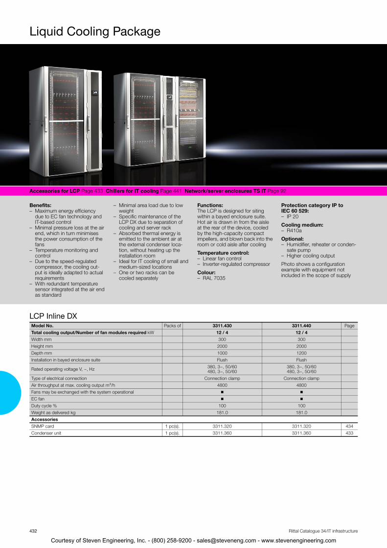
Liquid Cooling Package
Accessories for LCP Page 433 Chillers for IT cooling Page 441 Network/server enclosures TS IT Page 92
Benefits:– Maximum energy efficiency
due to EC fan technology and IT-based control
– Minimal pressure loss at the air end, which in turn minimises the power consumption of the fans
– Temperature monitoring and control
– Due to the speed-regulated compressor, the cooling out-put is ideally adapted to actual requirements
– Minimal area load due to low weight
– Specific maintenance of the LCP DX due to separation of cooling and server rack
– Absorbed thermal energy is emitted to the ambient air at the external condenser loca-tion, without heating up the installation room
– Ideal for IT cooling of small and medium-sized locations
– One or two racks can be cooled separately
Functions:The LCP is designed for siting within a bayed enclosure suite. Hot air is drawn in from the aisle at the rear of the device, cooled by the high-capacity compact impellers, and blown back into the room or cold aisle after cooling
Temperature control:– Linear fan control– Inverter-regulated compressor
Colour:– RAL 7035
Protection category IP to IEC 60 529:– IP 20
Cooling medium:– R410a
Optional:– Humidifier, reheater or conden-
sate pump– Higher cooling output
Photo shows a configuration example with equipment not included in the scope of supply
– With redundant temperature sensor integrated at the air end as standard
LCP Inline DXModel No. Packs of 3311.430 3311.440 PageTotal cooling output/Number of fan modules required kW 12 / 4 12 / 4Width mm 300 300Height mm 2000 2000Depth mm 1000 1200Installation in bayed enclosure suite Flush Flush
Rated operating voltage V, ~, Hz 380, 3~, 50/60480, 3~, 50/60
380, 3~, 50/60480, 3~, 50/60
Type of electrical connection Connection clamp Connection clampAir throughput at max. cooling output m³/h 4800 4800Fans may be exchanged with the system operational ◾ ◾EC fan ◾ ◾Duty cycle % 100 100Weight as delivered kg 181.0 181.0AccessoriesSNMP card 1 pc(s). 3311.320 3311.320 434Condenser unit 1 pc(s). 3311.360 3311.360 433
432 Rittal Catalogue 34/IT infrastructure
Courtesy of Steven Engineering, Inc. - (800) 258-9200 - [email protected] - www.stevenengineering.com

Rittal Catalogue 34/IT infrastructure
Courtesy of Steven Engineering, In
Liquid Cooling Package
Accessories for LCP CW/DXTouchscreen displayfor LCP Rack, Inline, CW The colour display offers the opportunity of directly monitoring key LCP functions and implementing set-tings.
For LCP CW Packs of Model No.3311.1303311.2303311.2603311.5303311.5403311.560
1 pc(s). 3311.030
Condenser unit The condenser unit is needed to operate the refrig-erant-based LCPs, and comprises the external con-denser and fan.
Refrigerant: – R410a
Note: – The pipework between the LCP DX and the con-
denser is not included with the supply.
For LCP DX Packs of Model No.3311.410 3311.4203311.4303311.440
1 pc(s). 3311.360
Vertical shielding for enclosure height 2000 mm To block the airflow on the left and right of the 482.6 mm (19˝) level.
Length: 1900 mm
Material: – Cellular PU foam– Flame-inhibiting to UL 94 (HF1) – Self-adhesive on one side
For sealing between
For enclosure width mm
Packs of Model No.
Side panel and 482.6 mm (19˝)
level
600 1 pc(s). 3301.380
800 1 pc(s). 3301.390
LCP and 482.6 mm (19˝)
level
600 1 pc(s). 3301.370
800 1 pc(s). 3301.320
Connection hose bottom and top Flexible connection hose, may be cut to required length, including union nuts on both sides for con-necting the LCP to existing pipework.
For LCP CW ThreadWater
connection from
Packs of Model No.
3311.130 3311.230 3311.260 3311.530 3311.540 3311.560
11/2˝ bottom/top 2 pc(s). 3311.040
Rear adaptorfor LCP Inline CWMay be positioned to the rear of the set forward LCP Inline to close the existing gap in the rear sec-tion.
For LCP Inline CW Packs of Model No.3311.5303311.560 1 pc(s). 3311.080
433
c. - (800) 258-9200 - [email protected] - www.stevenengineering.com

Liquid Cooling Package
434
Courtesy of Steven En
Accessories for LCP CW/DX
Rittal Catalogue 34/IT infrastructure
SNMP card For connecting LCP Rack/Inline DX units to the net-work.
For LCP DX Packs of Model No.3311.4103311.4203311.4303311.440
1 pc(s). 3311.320
Fan modulefor LCPTo increase the cooling output, individual fan mod-ules may be retro-fitted into the LCPs. This can also achieve redundancy or reduce the electric power consumption of the LCP.
For LCP Packs of Model No.3311.130, 3311.230, 3311.260, 3311.530, 3311.540, 3311.560
1 pc(s). 3311.011
The LCP 3311.130/.230/.530 (max. 30 kW) is supplied with one fan module as standard.
To achieve the max. cooling out-put of 30 kW, the customer/ser-vice should install two additional fan modules.
The LCP 3311.540 (max. 30 kW) is supplied with two fan modules as standard.
To achieve the max. cooling out-put of 30 kW, the customer/ser-vice should install two additional fan modules.
The LCP 3311.260/.560 (max. 55 kW) is supplied with four fan modules as standard.
To achieve the max. cooling out-put of 55 kW, the customer/ser-vice should install two additional fan modules.
gineering, Inc. - (800) 258-9200 - [email protected] - www.stevenengineering.com

Aisle containment
435Rittal Catalogue 34/IT infrastructure
Liquid Cooling Package Page 428 Network/server enclosures TS IT Page 90
Slimline door element with view-ing window and sliding door. Sta-ble roof elements in a composite metal with a high level of light per-meability. Where required, safety glass may also be used.
Applications:– Depending on the application,
aisle containment may be used with CRAC systems or LCP Inline as hot or cold aisle con-tainment.
Benefits:– Increased energy efficiency and
performance capability of cli-mate control.
– Superior output density is facili-tated, thanks to targeted cold air supply.
– Easily installed and retrofitted, as it is fully compatible with the TS 8 enclosure system.
– An inexpensive way to boost the performance of your exist-ing plant, lengthening the investment cycle until a replacement needs to be pur-chased.
Functions:Aisle containment is a combina-tion of door and roof compo-nents which facilitate consistent separation of the hot and cold air in the data centre. Such separa-tion is pivotal to saving energy and increasing the efficiency of the available climate control tech-nology.
Note:– Individual project planning only
Photo shows a configuration example with equipment not included in the scope of supply
Model No. 7999.922 Page
Courtesy of Steven Engineering, Inc. - (800) 258-9200 - [email protected] - www.stevenengineering.com

Roof-mounted cooling units
Climate control accessories Page 369
Temperature control:– Control of the server air infeed
temperature
Material:– Sheet steel
Colour:– RAL 7035
Protection category IP to IEC 60 529:– External circuit IP 34– Internal circuit IP 54
Supply includes:– Nano-coated condenser– Integral electric condensate
evaporation– Fully wired ready for connection– Drilling template– Assembly parts
Note:– A roof plate with cut-out to
match the enclosure dimen-sions is required
for cooling IT equipmentModel No. Packs of 3301.800 Page
Total cooling output L25 L35 W 3000Total cooling output L35 L45 W 3200Width mm 597Height mm 417Depth mm 895Rated operating voltage V, ~, Hz 230, 1~, 50Type of electrical connection Plug-in terminal stripPre-fuse (T) A 16Start-up current max. A 36Rated current max. A 9.2Refrigerant R134aPermissible operating pressure (p. max.) bar 25Duty cycle % 100Operating temperature range +10°C...+45°CSetting range +20°C...+25°CWeight as delivered kg 72.0AccessoriesCondensate hose 1 pc(s). 3301.612 377Door-operated switch 1 pc(s). 4127.010 639Air baffle plates see page 692Filter mats 3 pc(s). 3286.500 369436 Rittal Catalogue 34/IT infrastructure
Courtesy of Steven Engineering, Inc. - (800) 258-9200 - [email protected] - www.stevenengineering.com

Small cooling units
437
T
H
B
511 511
410450450
410
H
13.5
T B
tevenengineering.com
Rittal Catalogue 34/IT infrastructure
Roof-mounted fansfor TS, TS IT in the office sectorThis roof ventilation concept offers a wealth of per-formance, assembly and cost benefits associated with the use of integrated ventilation systems. This roof-mounted fan may be ordered with and without a roof plate. Another outstanding feature is the enor-mous volumetric flow in proportion to exceptionally low noise levels, making it ideal for use in sensitive office areas.
Technical specifications: – With 3164.620 pre-configured on the roof plate,
solid, based on TS– Easy assembly; no need to make mounting cut-
outs– Radial fan
Colour: – RAL 7035
Supply includes: – Fully wired ready for connection– Assembly parts
Technical details: Available on the Internet
Model No. 3164.620 3164.230 PageRated operating voltage V, ~, Hz: 230, 1~, 50/60 230, 1~, 50/60 Air throughput, unimpeded airflow m3/h 15001) 15001)
Version with roof plate
without roof plate
Width (B) mm 800 511Height (H) mm 240 227Depth (T) mm 800 511Power consumption W 68/81 68/81 Rated current A 0.3/0.35 0.3/0.35 Noise level dB (A) 40 40 Operating temperature range +20°C…+55°C +20 °C … +55 °C AccessoriesTemperature display in 1 U patch panel 7109.035 7109.035 379 Digital enclosure internal temperature display and thermostat 3114.200 3114.200 379 Enclosure internal thermostat 3110.000 3110.000 379
1) 800 m3/h at 40 Pa counterpressure using two vented base/plinth trim panels 8100.802 in the Flex-Block base/plinth system
Fan mounting platefor TS IT For active ventilation. For use in the cut-out inte-grated into the roof plate. The unit may optionally be extended with additional fans.
Technical specifications for one fan: – Fan expansion kit 7980.000, see page 438
Technical specifications of thermostat: – Rated operating voltage: 250 V – Temperature range: +5°C…+55°C
Colour: – RAL 7035
Supply includes: – 1 fan unit– 2 fans– 1 thermostat– 1 connection cable, top – Assembly parts
Note: – Connection via distributor box or country-specific
connector
Accessories:
– Fan expansion kit, see page 438
W x D mm
No. of prewired fans
No. of fans supported Model No.
800 x 600, 600 x 1000, 600 x 1200 2 3 5502.010 800 x 800, 800 x 1000, 800 x 1200 2 6 5502.020
Courtesy of Steven Engineering, Inc. - (800) 258-9200 - [email protected] - www.s
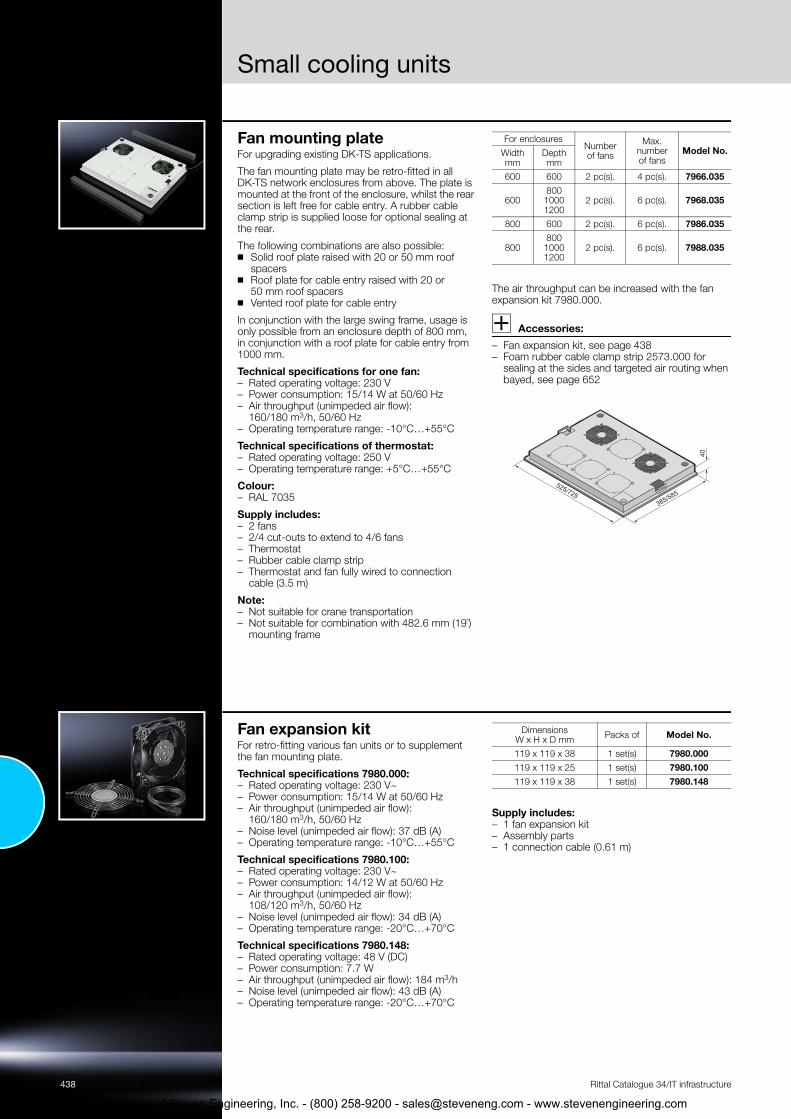
Small cooling units
438
Courtesy of Steven En
Rittal Catalogue 34/IT infrastructure
Fan mounting plate For upgrading existing DK-TS applications.
The fan mounting plate may be retro-fitted in all DK-TS network enclosures from above. The plate is mounted at the front of the enclosure, whilst the rear section is left free for cable entry. A rubber cable clamp strip is supplied loose for optional sealing at the rear.
The following combinations are also possible:◾ Solid roof plate raised with 20 or 50 mm roof
spacers ◾ Roof plate for cable entry raised with 20 or
50 mm roof spacers ◾ Vented roof plate for cable entry
In conjunction with the large swing frame, usage is only possible from an enclosure depth of 800 mm, in conjunction with a roof plate for cable entry from 1000 mm.
Technical specifications for one fan: – Rated operating voltage: 230 V – Power consumption: 15/14 W at 50/60 Hz – Air throughput (unimpeded air flow):
160/180 m3/h, 50/60 Hz – Operating temperature range: -10°C…+55°C
Technical specifications of thermostat: – Rated operating voltage: 250 V – Operating temperature range: +5°C…+55°C
Colour: – RAL 7035
Supply includes: – 2 fans– 2/4 cut-outs to extend to 4/6 fans – Thermostat – Rubber cable clamp strip – Thermostat and fan fully wired to connection
cable (3.5 m)
Note: – Not suitable for crane transportation– Not suitable for combination with 482.6 mm (19˝)
mounting frame
The air throughput can be increased with the fan expansion kit 7980.000.
Accessories:
– Fan expansion kit, see page 438 – Foam rubber cable clamp strip 2573.000 for
sealing at the sides and targeted air routing when bayed, see page 652
For enclosuresNumber of fans
Max. number of fans
Model No.Width mm
Depth mm
600 600 2 pc(s). 4 pc(s). 7966.035
60080010001200
2 pc(s). 6 pc(s). 7968.035
800 600 2 pc(s). 6 pc(s). 7986.035
80080010001200
2 pc(s). 6 pc(s). 7988.035
385/585525/725
40
Fan expansion kitFor retro-fitting various fan units or to supplement the fan mounting plate.
Technical specifications 7980.000: – Rated operating voltage: 230 V~ – Power consumption: 15/14 W at 50/60 Hz – Air throughput (unimpeded air flow):
160/180 m3/h, 50/60 Hz – Noise level (unimpeded air flow): 37 dB (A) – Operating temperature range: -10°C…+55°C
Technical specifications 7980.100: – Rated operating voltage: 230 V~ – Power consumption: 14/12 W at 50/60 Hz – Air throughput (unimpeded air flow):
108/120 m3/h, 50/60 Hz– Noise level (unimpeded air flow): 34 dB (A) – Operating temperature range: -20°C…+70°C
Technical specifications 7980.148: – Rated operating voltage: 48 V (DC) – Power consumption: 7.7 W – Air throughput (unimpeded air flow): 184 m3/h – Noise level (unimpeded air flow): 43 dB (A) – Operating temperature range: -20°C…+70°C
Supply includes: – 1 fan expansion kit– Assembly parts – 1 connection cable (0.61 m)
Dimensions W x H x D mm Packs of Model No.
119 x 119 x 38 1 set(s) 7980.000119 x 119 x 25 1 set(s) 7980.100119 x 119 x 38 1 set(s) 7980.148
gineering, Inc. - (800) 258-9200 - [email protected] - www.stevenengineering.com

Small cooling units
439
B
T
H
tevenengineering.com
Rittal Catalogue 34/IT infrastructure
Fan cross memberFor upgrading existing DK-TS applications.
Specifically for installing in one-piece perfo-rated sheet steel doors Given the growing packaging density in data com-munications and network enclosures, active, direct ventilation of the enclosure is essential. The fan cross member, which is attached to the tubular door frame of the rear or front door, supports horizontal air routing via the servers and therefore facilitates faster heat dissipation from active components.
Technical specifications: – Standard cross member with two fans– Air throughput, unimpeded airflow 600 m3/h– By adding two fan expansion kits, the air through-
put is increased to 1200 m3/h – The direction of air flow is easily reversed by
rotating the fan– Several cross members may be positioned in a
cascade arrangement– Simple mounting on the tubular door frame
Supply includes: – Fully wired ready for connection – Connection cable 2.5 m– Assembly parts
Note: – Only for mounting on the tubular door frame
Accessories:
– Fan expansion kit, see page 438
Technical details: Available on the Internet
For doors with width 600 mm
For doors with width 800 mm
Model No. 3165.630 PageRated operating voltage V, ~, Hz: 230, 1~, 50/60 Air throughput (unimpeded airflow) m3/h 600 Power consumption for two fans W 70/70 Rated current fan A 0.38/0.36 Width (B) mm 493 Height (H) mm 606Depth (T) mm 64.5Noise level dB (A) 55 Temperature range +20°C…+55°CColour RAL 7035AccessoriesDigital enclosure internal temperature display and thermostat 3114.200 379 Enclosure internal thermostat 3110.000 379
Model No. 3165.830 PageRated operating voltage V, ~, Hz: 230, 1~, 50/60 Air throughput (unimpeded airflow) m3/h 600 Power consumption for two fans W 70/70 Rated current fan A 0.38/0.36 Width (B) mm 693 Height (H) mm 606Depth (T) mm 64.5For doors with width (mm) 800Noise level dB (A) 55 Temperature range +20°C…+55°CColour RAL 7035AccessoriesDigital enclosure internal temperature display and thermostat 3114.200 379 Enclosure internal thermostat 3110.000 379
Fan expansion kitfor fan cross memberTo increase the air throughput of the fan cross member.
To fit fan cross member Model No.3165.630, 3165.830 3165.230
Courtesy of Steven Engineering, Inc. - (800) 258-9200 - [email protected] - www.s

Small cooling units
440
Courtesy of Steven En
Rittal Catalogue 34/IT infrastructure
Cover plates for fan panelsfor FlatBox To cover unused fan panels when using fan motors in the FlatBox.
Material: – Sheet steel
Surface finish: – Powder-coated
Colour: – RAL 7035
Supply includes: – Assembly parts
Packs of Model No.6 pc(s). 7507.760
Vent cover The ideal addition for incorporating sealed racks into an existing central climate control system. The stepped connection is suitable for standard pipe diameters 150 mm and 200 mm, thereby ensuring effective cooling thanks to targeted air exchange inside the rack.
Design: – Diameter of hose connection:
150 mm/200 mm – Maximum cut-out on roof plate:
380 mm x 230 mm
Material: – PET-G, transparent
Supply includes: – Assembly parts
Width mm
Height mm
Depth mm Packs of Model No.
450 144 300 1 pc(s). 7826.750
gineering, Inc. - (800) 258-9200 - [email protected] - www.stevenengineering.com
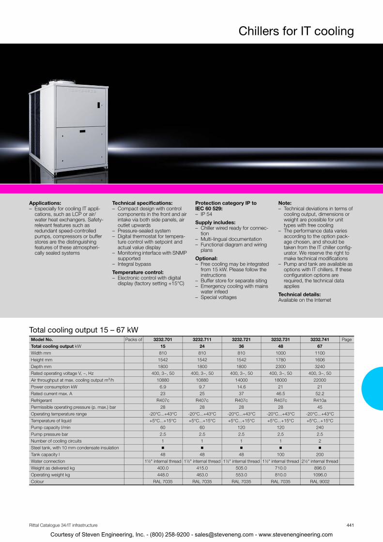
Chillers for IT cooling
Applications:– Especially for cooling IT appli-
cations, such as LCP or air/water heat exchangers. Safety-relevant features such as redundant speed-controlled pumps, compressors or buffer stores are the distinguishing features of these atmospheri-cally sealed systems
Technical specifications:– Compact design with control
components in the front and air intake via both side panels, air outlet upwards
– Pressure-sealed system – Digital thermostat for tempera-
ture control with setpoint and actual value display
– Monitoring interface with SNMP supported
– Integral bypass
Temperature control:– Electronic control with digital
display (factory setting +15°C)
Protection category IP to IEC 60 529:– IP 54
Supply includes:– Chiller wired ready for connec-
tion– Multi-lingual documentation– Functional diagram and wiring
plans
Optional:– Free cooling may be integrated
from 15 kW. Please follow the instructions
– Buffer store for separate siting – Emergency cooling with mains
water infeed – Special voltages
Note:– Technical deviations in terms of
cooling output, dimensions or weight are possible for unit types with free cooling
– The performance data varies according to the option pack-age chosen, and should be taken from the IT chiller config-urator. We reserve the right to make technical modifications
– Pump and tank are available as options with IT chillers. If these configuration options are required, the technical data applies
Technical details:Available on the Internet
Total cooling output 15 – 67 kWModel No. Packs of 3232.701 3232.711 3232.721 3232.731 3232.741 PageTotal cooling output kW 15 24 36 48 67Width mm 810 810 810 1000 1100Height mm 1542 1542 1542 1780 1606Depth mm 1800 1800 1800 2300 3240Rated operating voltage V, ~, Hz 400, 3~, 50 400, 3~, 50 400, 3~, 50 400, 3~, 50 400, 3~, 50Air throughput at max. cooling output m³/h 10880 10880 14000 18000 22000Power consumption kW 6.9 9.7 14.6 21 21Rated current max. A 23 25 37 46.5 52.2Refrigerant R407c R407c R407c R407c R410aPermissible operating pressure (p. max.) bar 28 28 28 28 45Operating temperature range -20°C...+43°C -20°C...+43°C -20°C...+43°C -20°C...+43°C -20°C...+43°CTemperature of liquid +5°C...+15°C +5°C...+15°C +5°C...+15°C +5°C...+15°C +5°C...+15°CPump capacity l/min 60 60 120 120 240Pump pressure bar 2.5 2.5 2.5 2.5 2.5Number of cooling circuits 1 1 1 1 2Steel tank, with 10 mm condensate insulation ◾ ◾ ◾ ◾ ◾Tank capacity l 48 48 48 100 200Water connection 1½" internal thread 1½" internal thread 1½" internal thread 1½" internal thread 2½" internal threadWeight as delivered kg 400.0 415.0 505.0 710.0 896.0Operating weight kg 448.0 463.0 553.0 810.0 1096.0Colour RAL 7035 RAL 7035 RAL 7035 RAL 7035 RAL 9002
441Rittal Catalogue 34/IT infrastructure
Courtesy of Steven Engineering, Inc. - (800) 258-9200 - [email protected] - www.stevenengineering.com

Chillers for IT cooling
Total cooling output 155 – 261 kW
Water connection 2½" internal thread 2½" internal thread 2½" internal thread 2½" internal thread 2½" internal threadWeight as delivered kg 896.0 906.0 912.0 1000.0 1000.0Operating weight kg 1096.0 1106.0 1112.0 1300.0 1300.0Colour RAL 9002 RAL 9002 RAL 9002 RAL 9005 RAL 9005
Model No. Packs of 3232.801 3232.811 3232.821 3232.891 3232.831 PageTotal cooling output kW 155 172 196 235 261Width mm 1100 1100 1100 1500 2200Height mm 1875 1875 1875 1975 2450Depth mm 3240 3240 4240 4350 3400Rated operating voltage V, ~, Hz 400, 3~, 50 400, 3~, 50 400, 3~, 50 400, 3~, 50 400, 3~, 50Air throughput at max. cooling output m³/h 32600 32600 50000 49000 72800Power consumption kW 47 52 60 70 80Rated current max. A 108 120 127 149 181
Refrigerant R410a R410a R410a R410a R410aPermissible operating pressure (p. max.) bar 45 45 45 45 45Operating temperature range -20°C...+43°C -20°C...+43°C -20°C...+43°C -20°C...+43°C -20°C...+43°CTemperature of liquid +5°C...+15°C +5°C...+15°C +5°C...+15°C +5°C...+15°C +5°C...+15°CPump capacity l/min 500 500 500 500 810Pump pressure bar 2.5 2.5 2.5 2.5 2.5Number of cooling circuits 2 2 2 2 2Steel tank, with 10 mm condensate insulation ◾ ◾ ◾ ◾ ◾Tank capacity l 300 300 300 300 700Water connection 2½" internal thread 2½" internal thread 2½" internal thread 2½" internal thread 3" internal threadWeight as delivered kg 1000.0 1000.0 1000.0 1900.0 2500.0Operating weight kg 1300.0 1300.0 1300.0 2200.0 3200.0Colour RAL 9002 RAL 9002 RAL 9002 RAL 9002 RAL 9002Total cooling output 77 – 124 kWModel No. Packs of 3232.751 3232.761 3232.771 3232.781 3232.791 PageTotal cooling output kW 77 88 99 117 124Width mm 1100 1100 1100 1100 1100Height mm 1606 1606 1606 1875 1875Depth mm 3240 3240 3240 3240 3240Rated operating voltage V, ~, Hz 400, 3~, 50 400, 3~, 50 400, 3~, 50 400, 3~, 50 400, 3~, 50Air throughput at max. cooling output m³/h 22000 27000 27000 34100 34100Power consumption kW 24 26 29 36 41Rated current max. A 59.2 64.2 69.2 84.1 89.1Refrigerant R410a R410a R410a R410a R410aPermissible operating pressure (p. max.) bar 45 45 45 45 45Operating temperature range -20°C...+43°C -20°C...+43°C -20°C...+43°C -20°C...+43°C -20°C...+43°CTemperature of liquid +5°C...+15°C +5°C...+15°C +5°C...+15°C +5°C...+15°C +5°C...+15°CPump capacity l/min 240 240 240 470 470Pump pressure bar 2.5 2.5 2.5 2.5 2.5Number of cooling circuits 2 2 2 2 2Steel tank, with 10 mm condensate insulation ◾ ◾ ◾ ◾ ◾Tank capacity l 200 200 200 300 300
442 Rittal Catalogue 34/IT infrastructure
Courtesy of Steven Engineering, Inc. - (800) 258-9200 - [email protected] - www.stevenengineering.com

Chillers for IT cooling
Total cooling output 291 – 481 kWModel No. Packs of 3232.841 3232.851 3232.861 3232.871 3232.881 PageTotal cooling output kW 291 326 387 430 481Width mm 2200 2200 2200 2200 2200Height mm 2450 2450 2450 2450 2450Depth mm 3400 3400 4250 4250 4250Rated operating voltage V, ~, Hz 400, 3~, 50 400, 3~, 50 400, 3~, 50 400, 3~, 50 400, 3~, 50Air throughput at max. cooling output m³/h 71500 70200 106200 104100 102000Power consumption kW 93 106 121 141 159Rated current max. A 203 225 293 307 336Refrigerant R410a R410a R410a R410a R410aPermissible operating pressure (p. max.) bar 45 45 45 45 45Operating temperature range -20°C...+43°C -20°C...+43°C -20°C...+43°C -20°C...+43°C -20°C...+43°CTemperature of liquid +5°C...+15°C +5°C...+15°C +5°C...+15°C +5°C...+15°C +5°C...+15°CPump capacity l/min 810 810 1200 1200 1200Pump pressure bar 2.5 2.5 2.5 2.5 2.5Number of cooling circuits 2 2 2 2 2Steel tank, with 10 mm condensate insulation ◾ ◾ ◾ ◾ ◾Tank capacity l 700 700 700 700 700Water connection 3" internal thread 3" internal thread 4" internal thread 4" internal thread 4" internal threadWeight as delivered kg 2700.0 2800.0 3100.0 3000.0 3600.0Operating weight kg 3400.0 3500.0 3800.0 3700.0 4300.0Colour RAL 9002 RAL 9002 RAL 9002 RAL 9002 RAL 9002443Rittal Catalogue 34/IT infrastructure
New
RiMatrix S
see page 398
Courtesy of Steven Engineering, Inc. - (800) 258-9200 - [email protected] - www.stevenengineering.com

444 Rittal Catalogue 34/IT infrastructure
1
2
1
4
2
1
3
Courtesy of Steven Engineering, Inc. - (800) 258-9200 - [email protected] - www.stevenengineering.com
Rittal Catalogue 34/IT infrastructure
Courtesy of Steven Engineering, Inc. - (800) 2
IT monitoring
CMC III – Monitoring systemCMC III system representation ....................................................................446CMC III system overview.............................................................................448CMC III Processing Unit/Compact ..............................................................450
CMC III sensors/accessoriesCMC III control units/CMC III sensors .........................................................451Interface for CMC II sensors .......................................................................451Access System...........................................................................................452Interface for PSM, PCU ..............................................................................452PSM and slave PDU for direct connection ..................................................453
CMC III accessoriesPower supply unit .......................................................................................457Programming cable ....................................................................................457CAN bus connection cable .........................................................................457Connection cable/extension........................................................................457Extension cable RJ 12 ................................................................................458Mounting unit, 1 U ......................................................................................458Mounting unit .............................................................................................458
Door control systemDoor control system ...................................................................................459Door control module...................................................................................460Door kit ......................................................................................................460Door comfort handle...................................................................................460Door switch ................................................................................................460
Monitor/keyboard unitMonitor/keyboard unit, 1 U .........................................................................461KVM switch ................................................................................................461
Dynamic Rack ControlRFID aerial ..................................................................................................462RFID tags ...................................................................................................462RFID controller............................................................................................462CMC III CAN bus DRC................................................................................462
Management softwareRiZone........................................................................................................463Server shutdown software ..........................................................................463
Your benefits◾ A better overview of your IT infrastructure◾ Enhanced security◾ Automated processes◾ Exceptional cost efficiency◾ High energy savings◾ Simple project management◾ Fast installation◾ Flexible, individual solutions with standard products from Rittal ◾ High standard of quality with coordinated standard products
445
Sample applications� CMC III, see page 449
� Liquid Cooling Package LCP, see page 428
� Monitor/keyboard unit, see page 461
� Electric comfort handle TS 8, see page 460
58-9200 - [email protected] - www.stevenengineering.com

CMC III – Monitoring system
CMC III Processing Unit1
32
12
Computer Multi Control (CMC) is an alarm system for network and server enclosures, cases, containers and rooms.◾ It monitors temperatures, humidity, access, smoke,
energy and many other physical ambient parameters.◾ It is a modular system that can be flexibly adapted
to meet the customer's specific monitoring require-ments.
◾ User benefits plus exceptional savings are achieved, thanks to monitoring via the network and the auto-mation of security processes.
Further information can be found at: www.rittal.com
446 Rittal Catalogue 34/IT infrastructure
11
10
8
9
4
7
Courtesy of Steven Engineering, Inc. - (800) 258-9200 - [email protected] - www.stevenengineering.com

447Rittal Catalogue 34/IT infrastructure
� CMC III Processing Unit, see page 449 � Power supply� Redundant power supply � CMC III I/O unit� CMC III power unit� CMC III PSM measuring bar for direct connection! Up to 16 CAN bus systems may be connected# CMC III vandalism sensor $ CMC III temperature sensor&* CAN bus sensor for connection of CMC II sensors&; CMC III CAN bus access&< Up to 16 CAN bus systems may be connected
6
5
Courtesy of Steven Engineering, Inc. - (800) 258-9200 - [email protected] - www.stevenengineering.com

448
Courtesy of Steven En
CMC III Processing Unit Compact
+ –
0°0°
System overview
Rittal Catalogue 34/IT infrastructure
Up to 4 CAN bus com-ponents are supported1)
CMC III CAN bus sensoras adaptor for CMC II sensors
CMC III CAN bus accesswith integral IR access sensor
Two integral digital inputs
Internal infrared access sensor
RJ 12/RS232 accessory modules:Display unit, ISDN unit, GSM unit
Ethernet 10/100 BaseT RJ 45 with PoE:Ethernet interface to IEEE 802.3Over 10/100 BaseT full duplex 10/100 Mbit/s
Voltage supply 24 V (DC) and Redundant voltage supply 24 V (DC) Power packs, see page 457
Alarm relay output:Changeover contact for safety extra-low voltage
1) Depending on power supply/connection combinations, see page 451
Mini USB:Programming cable 7030.080 is required for programming, see page 457
CMC III sensorsfor direct connection
CMC III Processing Unit Compact
CMC III CAN bus unit
Interfaces unit for connect-ing CMC II accessories
Connection for other products, see page 452
2) External 24 V (DC) supply via 7030.060 required
Model No.
CMC III CAN bus unit 7030.030
24 V (DC)2)
CAN bus 1
External temperature sensor (included in the supply of PUC)
Note: Server shutdown software for CMC III is required to shut down the server, see page 463
gineering, Inc. - (800) 258-9200 - [email protected] - www.stevenengineering.com

CMC III Processing Unit
449
tevenengineering.com
+ –
12
0°0°
System overview
Rittal Catalogue 34/IT infrastructure
Up to 16 CAN bus sys-tems are supported1)
CMC III sensorsfor direct connection
CMC III CAN bus access with integral IR access sensor
Two integral digital inputs
Internal infrared access sensor
Ethernet 10/100 BaseT RJ 45 with PoE:Ethernet interface to IEEE 802.3 via 10/100 BaseT full duplex 10/100 Mbit/s
Voltage supply 24 V (DC) and redundant voltage supply 24 V (DC)Power packs, see page 457
Alarm relay output: Changeover contact for safety extra-low voltage
USB master for data logging and update
Mini USB:Programming cable 7030.080 is required for programming, see page 457
Contains
8 digital inputs
and 4 relay outputs
1
2
Functions:– Switching and measuring
voltage, current, powerand work
– With two outputs – Also for the activation of
fans
Interfaces unit for connect-ing CMC II accessories
Connection for other products, see page 452
2) External 24 V (DC) supplyvia 7030.060 required
SD card insert: for data logging
External temperature sensor(included in the supply of PU)
Control units
CMC III I/O unit CMC III power unit
CMC III CAN bus unit
Model No.
CMC III I/O unit 7030.040
Model No.
CMC III Power unit 7030.050
Model No.
CMC III CAN bus unit 7030.030
Up to 16 CAN bus sys-tems are supported1)
CMC III Processing Unit
CMC III CAN bus sensoras adaptor for CMC II sensors
CAN bus 2
CAN bus 1
1) Depending on power supply/connectioncombinations, see page 451
24 V (DC)2)
RJ 12/RS232 accessory modules:Display unit, ISDN unit, GSM unit
Courtesy of Steven Engineering, Inc. - (800) 258-9200 - [email protected] - www.s
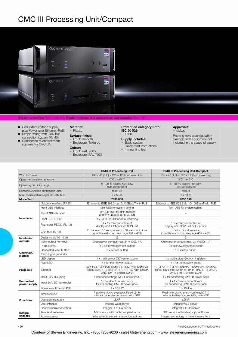
MC III Processing Unit/Compact
CWO
Sy
◾
◾
◾
CMC III Processing Unit CMC III Processing Unit Compact
stem overview Page 448/449 Basic modules and connection accessories Page 451
Redundant voltage supply, plus Power over Ethernet (PoE)Simple wiring with CAN bus connection system (RJ 45)Connection to control room systems via OPC UA
Material: – Plastic
Surface finish: – Front: Smooth – Enclosure: Textured
Colour: – Front: RAL 9005– Enclosure: RAL 7035
Protection category IP to IEC 60 529: – IP 30
Supply includes: – Basic system – Quick-start instructions – 4 mounting feet
Approvals: – cULus
Photo shows a configuration example with equipment not included in the scope of supply
x H x D mm 138 x 40 (1 U) x 120 + 12 (front assembly) 138 x 40 (1 U) x 120 + 12 (front assembly) perating temperature range 0°C…+45°C 0°C…+45°C
Operating humidity range 5 – 95 % relative humidity, non-condensing
5 – 95 % relative humidity, non-condensing
Sensors/CAN bus connection units max. 32 max. 4Max. overall cable length for CAN bus 2 x 50 m 1 x 50 m Model No. 7030.000 7030.010
Interfaces
Network interface (RJ 45) Ethernet to IEEE 802.3 via 10/100BaseT with PoE Ethernet to IEEE 802.3 via 10/100BaseT with PoEFront USB interface Mini USB for system setting Mini USB for system setting
Rear USB interface For USB stick for data records and SW updates up to 32 GB –
Front SD-HC slot 1 x up to 32 GB for data recording –
Rear serial RS232 (RJ 12) 1 x for the connection of display unit, GSM unit or ISDN unit
1 x for the connection of display unit, GSM unit or ISDN unit
CAN bus (RJ 45) 2 x for max. 16 sensors each = 32 sensors in total (quantity restriction, see page 451 – 453)
1 x for max. 4 sensors (quantity restriction, see page 451 – 453)
Inputs and outputs
Digital inputs (terminal) 2 2 Relay output (terminal) Changeover contact max. 24 V (DC), 1 A Changeover contact max. 24 V (DC), 1 A
Operation/signals
Push-button 1 x acknowledgement button 1 x acknowledgement buttonConcealed reset button 1 x service button 1 x service buttonPiezo signal generator 1 1 LED display 1 x multi-colour OK/warning/alarm 1 x multi-colour OK/warning/alarmRear LED 1 x for the network status 1 x for the network status
Protocols EthernetTCP/IPv4, TCP/IPv6, SNMPv1, SNMPv2c, SNMPv3, Telnet, SSH, FTP, SFTP, HTTP, HTTPS, NTP, DHCP,
DNS, SMTP, Syslog, LDAP
TCP/IPv4, TCP/IPv6, SNMPv1, SNMPv2c, SNMPv3, Telnet, SSH, FTP, SFTP, HTTP, HTTPS, NTP, DHCP,
DNS, SMTP, Syslog, LDAP
Redundant power supply
Input 24 V DC (jack) 1 x for connecting CMC III power pack 1 x for connecting CMC III power pack
Input 24 V DC (terminals) 1 x for direct connection or for connecting CMC III power pack
1 x for direct connection or for connecting CMC III power pack
Power over Ethernet PoE 1 x 15.4 W 1 x 15.4 W
Functions
Time function Real-time clock, energy-buffered (24 h) without battery/accumulator, with NTP
Real-time clock, energy-buffered (24 h) without battery/accumulator, with NTP
User administration LDAP LDAPUser interface Integral WEB server Integral WEB serverControl room connection Integral OPC UA server Integral OPC UA server
Integral sensors
Temperature sensor NTC sensor with cable, supplied loose NTC sensor with cable, supplied looseAccess sensor Infrared technology in the enclosure front Infrared technology in the enclosure front
450 Rittal Catalogue 34/IT infrastructure
Courtesy of Steven Engineering, Inc. - (800) 258-9200 - [email protected] - www.stevenengineering.com

CMC III
Control units for CMC III Processing Unit
Model No.PU
Compact PU Page
Maximum quantityCMC III I/O Unit, 8 digital inputs + 4 relay outputs 7030.040 – 16 454 CMC III Power Unit, 1 input (C14) + 2 outputs (C13) 230 V, 50/60 Hz – For switching 10 A total current (fan/heater etc.) – For measuring current, voltage, power, energy
7030.050 – 16 454
Also required:– CAN bus connection cable 7030.090/.095,
see page 457
– Mounting unit, 1 U, 7030.070, see page 458CMC III sensors for direct connection
Model No.PU
Compact PU Page
Maximum quantityTemperature sensor with external sensor 7030.110 4 32 454 Temperature/humidity sensor 7030.111 4 32 454 Infrared access sensor 7030.120 4 32 454 Vandalism sensor 7030.130 4 32 454 Analog airflow sensor 7030.140 4 101) 454 Analog differential pressure sensor 7030.150 4 32 454 Universal sensor (2x digital input and 4 – 20 mA) 7030.190 4 32 454
1) Max. 5 pieces for power supply with PoE
Also required:– CAN bus connection cable 7030.090/.095,
see page 457
451
tevenengineering.com
Sensors/accessories
Rittal Catalogue 34/IT infrastructure
Interface for CMC II sensors
Model No.PU
Compact PU Page
Maximum quantityCMC III CAN bus sensor 7030.100 4 32 – For connecting the following products: 5 x access sensors (packs of 2), connect a max. of 5 in series 7320.530 ◾ ◾ 455 1 x smoke detector 7320.560 ◾ ◾ 455 1 x motion detector 7320.570 ◾ ◾ 455 1 x leakage sensor 7320.630 ◾ ◾ 455 1 x leakage sensor, with sensor length 15 m 7320.631 ◾ ◾ 455 1/3 x fire detector and extinguisher system DET-AC Plus with 3 messages 7338.120 ◾ ◾ 473 1/3 x early fire detector system DET-AC Plus with 3 messages 7338.220 ◾ ◾ 473 1/2 x door control system for one rack 7320.790 ◾ ◾ 460
Also required:– CAN bus connection cable 7030.090/.095,
see page 457
Courtesy of Steven Engineering, Inc. - (800) 258-9200 - [email protected] - www.s

CMC II
452
Courtesy of Steven Engineering, Inc. - (8
I
AccessoriesRittal Catalogue 34/IT infrastructure
Access system The CAN bus access is designed for one door. It has an integral IR access sensor and may be con-nected to one handle system and one reader unit.
Also required:– CAN bus connection cable 7030.090/.095,
see page 457
Model No.PU
Compact PU Page
Maximum quantityCMC III CAN bus access 7030.200 2 161) – For connection to handle: 1 x TS 8 handle with master key function 7320.721 2 161) 455 For connection to reader unit: 1 x CMC III coded lock 7030.220 2 161) 455 1 x CMC III transponder reader 7030.230 2 161) 455
1) Max. 5 pieces for power supply with PoE
Interface for PSM, PCU The products listed may be connected to the PU/PU Compact via CAN bus unit 7030.030, see page 456.
Accessories:
– Power supply unit 7030.060 and connection cable 7200.210, see page 457
– CAN bus connection cable 7030.090/.095, see page 457
– Mounting unit, 1 U, 7030.070, see page 458
Note: – Allow one power pack 7030.060 for every
CMC III CAN bus unit
Model No.PU
Compact PU Page
Maximum quantityCMC III CAN bus unit 7030.030 1 4 456 For connecting the following products: 2 x 4 x Rittal Power Control Unit (PCU) 8-way 7200.001 ◾ ◾ 412 2 x 4 x Rittal Power Control Unit (PCU) C13 LED, 8-way 7859.225 ◾ ◾ 412 2 x 4 x Rittal Power Control Unit (PCU) C13/19 LED, 6-way 7859.235 ◾ ◾ 412 2 x 4 x PSM socket module C13, 8-way 7856.201 ◾ ◾ 411 2 x 4 x PSM socket module C13/earthing-pin, 6-way 7856.203 ◾ ◾ 411 2 x 4 x PSM socket module C13/19, 6-way 7856.204 ◾ ◾ 411 2 x 4 x PSM socket module C13/earthing-pin LED, 6-way 7859.212 ◾ ◾ 411 2 x 4 x PSM socket module C13 LED, 8-way 7859.222 ◾ ◾ 411 2 x 4 x PSM socket module C13/19 LED, 6-way 7859.232 ◾ ◾ 411
00) 258-9200 - [email protected] - www.stevenengineering.com

CMC III
453
tevenengineering.com
Accessories
Rittal Catalogue 34/IT infrastructure
PSM and slave PDU for direct connection
Model No.PU
Compact PU Page
Maximum quantityPSM measuring bars 16 A, with 2 infeeds 7859.050 4 8 410 PSM measuring bars 32 A, with 1 infeed 7859.053 4 8 410 PSM MID measuring module 16 A, with 2 infeeds 7859.312 4 8 421 PSM MID measuring module 32 A, with 2 infeeds 7859.332 4 8 421 Slave PDU international, managed, 16 A, 12 x C13 7955.901 3 6 417 Slave PDU international, managed, 16 A, 24 x C13, 4 x C19 7955.910 3 6 417 Slave PDU international, managed, 32 A, 24 x C13, 4 x C19 7955.911 3 6 417 Slave PDU international, managed, 16 A, 18 x C13, 3 x C19 7955.931 3 6 417 Slave PDU international, managed, 16 A, 24 x C13, 6 x C19 7955.932 3 6 417 Slave PDU international, managed, 32 A, 24 x C13, 6 x C19 7955.933 3 6 417 Slave PDU UK, managed, 13 A, 16 x UK 7955.940 3 6 418 Slave PDU UK, managed, 16 A, 16 x UK, 4 x C19 7955.941 3 6 418 Slave PDU UK, managed, 32 A, 16 x UK, 4 x C19 7955.942 3 6 418
Accessories:
– CAN bus connection cable 7030.090/.095, see page 457
Courtesy of Steven Engineering, Inc. - (800) 258-9200 - [email protected] - www.s
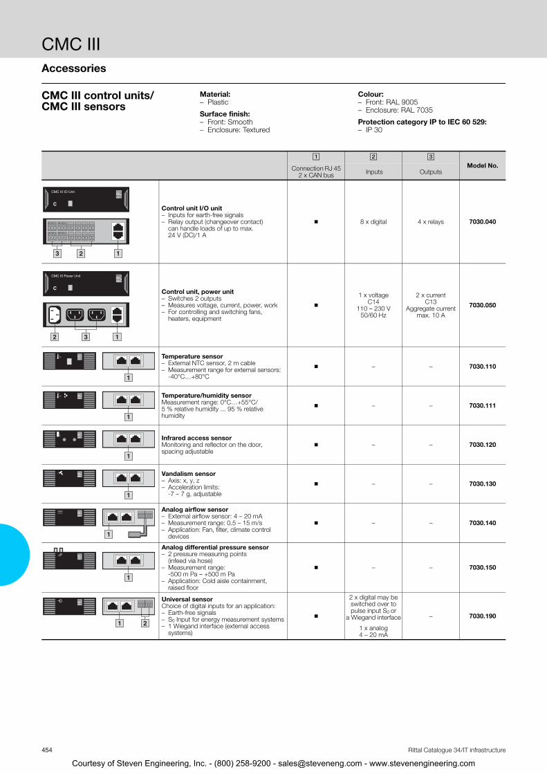
CMC IIIAccessories
454 Rittal Catalogue 34/IT infrastructure
CMC III control units/CMC III sensors
Material: – Plastic
Surface finish:– Front: Smooth – Enclosure: Textured
Colour: – Front: RAL 9005 – Enclosure: RAL 7035
Protection category IP to IEC 60 529: – IP 30
� � �Model No. Connection RJ 45
2 x CAN bus Inputs Outputs
Control unit I/O unit – Inputs for earth-free signals– Relay output (changeover contact)
can handle loads of up to max. 24 V (DC)/1 A
◾ 8 x digital 4 x relays 7030.040
Control unit, power unit – Switches 2 outputs– Measures voltage, current, power, work– For controlling and switching fans,
heaters, equipment
◾
1 x voltage C14
110 – 230 V50/60 Hz
2 x current C13
Aggregate current max. 10 A
7030.050
Temperature sensor – External NTC sensor, 2 m cable– Measurement range for external sensors:
-40°C…+80°C
◾ – – 7030.110
Temperature/humidity sensorMeasurement range: 0°C…+55°C/5 % relative humidity ... 95 % relative humidity
◾ – – 7030.111
Infrared access sensorMonitoring and reflector on the door, spacing adjustable
◾ – – 7030.120
Vandalism sensor – Axis: x, y, z– Acceleration limits:
-7 – 7 g, adjustable
◾ – – 7030.130
Analog airflow sensor– External airflow sensor: 4 – 20 mA– Measurement range: 0.5 – 15 m/s– Application: Fan, filter, climate control
devices
◾ – – 7030.140
Analog differential pressure sensor– 2 pressure measuring points
(infeed via hose)– Measurement range:
-500 m Pa – +500 m Pa– Application: Cold aisle containment,
raised floor
◾ – – 7030.150
Universal sensorChoice of digital inputs for an application:– Earth-free signals– S0 Input for energy measurement systems– 1 Wiegand interface (external access
systems)
◾
2 x digital may be switched over to pulse input S0 or
a Wiegand interface
1 x analog4 – 20 mA
– 7030.190
23
CMC III IO Unit
C
NC NO C NC NO C
NC NO C NC NO C
1
12 3
CMC III Power Unit
C
C°
1
1
C°
1
1
1
1
∆P
1 2
Courtesy of Steven Engineering, Inc. - (800) 258-9200 - [email protected] - www.stevenengineering.com

CMC IIIAccessories
455Rittal Catalogue 34/IT infrastructure
Interface for CMC II sensors
Access system
� � � Model No. Connection RJ 45
2 x CAN bus Input RJ 12 Output RJ 12
�CAN bus sensor For connecting one CMC II sensor ◾ 1 x – 7030.100
�CMC II access sensor – Sensor: Reed contact/magnet– Max. 5 reed contacts in series– 2 m cable included with the supply
– – 1 x 7320.530
�CMC II smoke detector Sensor: Visual 2 m cable included with the supply
– – 1 x 7320.560
�CMC II motion detector– Sensor: Infrared– 2 m cable included with the supply
– – 1 x 7320.570
�CMC II leakage sensor– Sensor: Point infrared sensor– 2 m cable included with the supply
– – 1 x 7320.630
�CMC II leakage sensor 15 m – Sensor: 15 sensitive cables – 2 m cable included with the supply
– – 1 x 7320.631
Connection Inputs Outputs
Model No.� � � � � RJ 45
2 x CAN bus RJ 12 Flat-pin connector RJ 12 Flat-pin
connector
�CAN bus access – For connecting one handle and
one reader unit for door monitoring– Integral IR access sensor
◾ 1 x 1 x – – 7030.200
�Handles – TS 8 handle with master key
function
– – – 1 x – 7320.721
– Handle monitoring – Rated voltage: 24 V (DC) – 3 m cable, 2 m extension cable
included with the supply
�CMC III reader units– Coded lock – Transponder reader
– – – – 1 x 7030.220 7030.230
– Numerical code from 0 – 8 digits may be selected
– Transponder technology: Mifare– 3 m cable included with the supply
1 2
CMC III CAN Bus Sensor
2
1
3
4
5
6
3
3
3
3
3
2
1
3
4
5
CMC III CAN Bus Access
1 2 3
Courtesy of Steven Engineering, Inc. - (800) 258-9200 - [email protected] - www.stevenengineering.com

CMC IIIAccessories
Interface for PSM, PCU Material: – Plastic
Surface finish:– Front: Smooth – Enclosure: Textured
Colour: – Front: RAL 9005 – Enclosure: RAL 7035
Protection category IP to IEC 60 529: – IP 30
Connection RJ 45
Model No.� � �2 x CAN bus Inputs
CAN bus unit For connecting:– PSM socket strips– PCU 482.6 mm (19˝) socket
strips
◾ 2 x
for PSM, PCU,see page 452
For operating the required
connection clamp for the 24 V power
pack 7030.060
7030.030
CAN bus DRC For connecting:– RFID controller 7890.500
◾ Max. 1 x
RFID controller,see page 462
Connection clamps for the 24 V power
pack (optional) 7030.060
7030.550
CMC III CAN Bus Unit
C
+ –
123
CMC III CAN Bus DRC
C
– +
123
456 Rittal Catalogue 34/IT infrastructure
PSM – MID measuring module
see page 421
New
Courtesy of Steven Engineering, Inc. - (800) 258-9200 - [email protected] - www.stevenengineering.com

CMC III
457
tevenengineering.com
Accessories
Rittal Catalogue 34/IT infrastructure
Power supply unitfor PU, PU Compact, CAN bus unit, CAN bus DRC, Door Control System.
Technical specifications: – Input voltage: 100 – 240 V / 50/60 Hz – Output voltage: 24 V (DC)/2.5 A – Length of 24 V DC connection cable: 0.6 m
Supply includes:– 4 mounting feet
Also required:– Connection cable, see page 457
Accessories:
– Mounting unit, see page 458
Packs of Model No.1 pc(s). 7030.060
Programming cable For commissioning the Processing Unit (PU) or PU Compact.
Supply includes:– CD with driver and system description
Packs of Model No.1 pc(s). 7030.080
CAN bus connection cable This can be used to connect the PU with the CAN bus sensors III, units III, control units III as a bus. Also for cabling the CAN bus sensors III, units III, control units III together.
CMC III CAN bus connection cable
Lengthm
Packs of Model No.
RJ 45 0.5 1 pc(s). 7030.090RJ 45 1 1 pc(s). 7030.091RJ 45 1.5 1 pc(s). 7030.092RJ 45 2 1 pc(s). 7030.093RJ 45 3 1 pc(s). 7030.480RJ 45 4 1 pc(s). 7030.490RJ 45 5 1 pc(s). 7030.094RJ 45 10 1 pc(s). 7030.095
Connection cable/extensionFor connecting to:◾ CMC III power pack C13◾ CMC III power unit C13◾ PCU C19 ◾ PDU C19
Technical specifications:– PVC cable, 3-pole, with IEC cable coupling
(non-heating appliances) with contact protection CEE22
– Length: Minimum 1.8 m
Country Version
Voltage Volt Packs of Model No.
D/F/B/C13 230 1 pc(s). 7200.210Non-heating
appliance extension C13/C14
230/115 1 pc(s). 7200.215
Connection cable D/C19 230/115 1 pc(s). 7200.216
Connection cable C19/C20 230/115 1 pc(s). 7200.217
Courtesy of Steven Engineering, Inc. - (800) 258-9200 - [email protected] - www.s
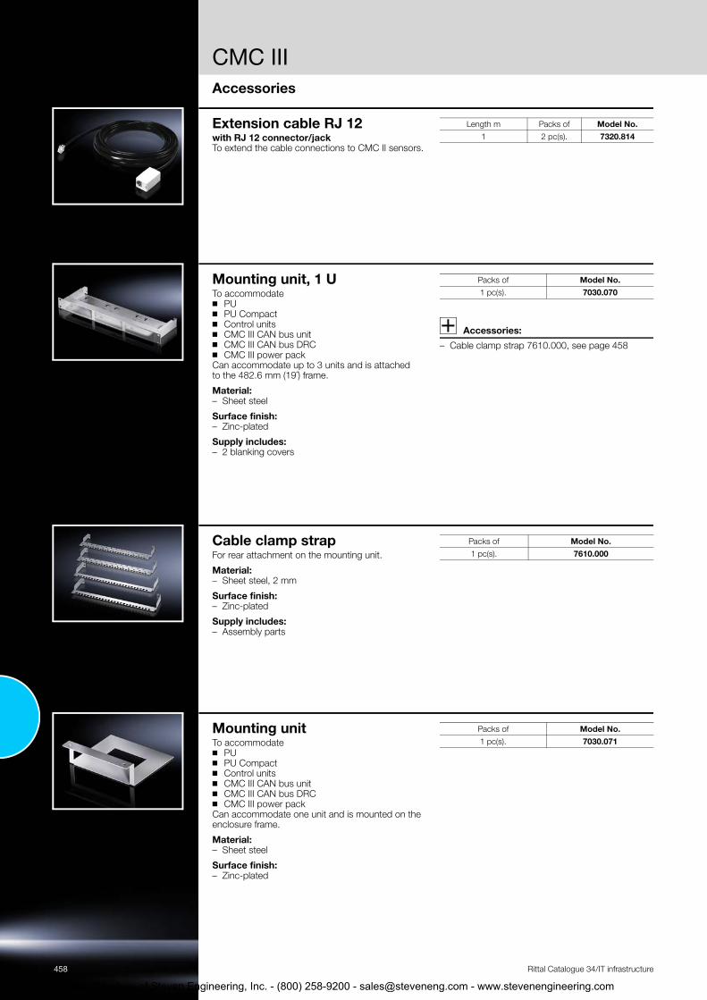
CMC III
458
Courtesy of Steven En
Accessories
Rittal Catalogue 34/IT infrastructure
Extension cable RJ 12with RJ 12 connector/jack To extend the cable connections to CMC II sensors.
Length m Packs of Model No.1 2 pc(s). 7320.814
Mounting unit, 1 UTo accommodate ◾ PU◾ PU Compact◾ Control units◾ CMC III CAN bus unit◾ CMC III CAN bus DRC◾ CMC III power pack Can accommodate up to 3 units and is attached to the 482.6 mm (19˝) frame.
Material:– Sheet steel
Surface finish:– Zinc-plated
Supply includes:– 2 blanking covers
Accessories:
– Cable clamp strap 7610.000, see page 458
Packs of Model No.1 pc(s). 7030.070
Cable clamp strapFor rear attachment on the mounting unit.
Material:– Sheet steel, 2 mm
Surface finish:– Zinc-plated
Supply includes:– Assembly parts
Packs of Model No.1 pc(s). 7610.000
Mounting unit To accommodate ◾ PU◾ PU Compact◾ Control units◾ CMC III CAN bus unit◾ CMC III CAN bus DRC◾ CMC III power pack Can accommodate one unit and is mounted on the enclosure frame.
Material:– Sheet steel
Surface finish:– Zinc-plated
Packs of Model No.1 pc(s). 7030.071
gineering, Inc. - (800) 258-9200 - [email protected] - www.stevenengineering.com

Door control system
Door control system◾ Automation adjustable via CMC◾ Manual and automatic door opening◾ Automatic opening in case of power failure
Note: To be connected at rear: – Door kit
2 door kits and 2 door kit extensions for LCP may be connected to one door control module
– Door comfort handle or door switch Up to 2 door comfort handles/door switches may be connected for manual opening
– Automatic door opening is achieved by connect-ing to the PU/PU Compact. Independently of this, the doors may be opened via the door comfort handle/door switch
– In the event of a power failure, the doors will also open
– Door kit extension for LCP must be backed up with a UPS
– The front and rear door must always be opened
Also required:– CMC III processing unit/compact, see page 450 – CAN bus sensor, see page 451
System diagram Door control system:◾ A maximum of 16 door control systems per Processing Unit◾ A maximum of 2 door control systems may be connected per Processing Unit Compact
1
2 3
4
CMC III – Processing Unit– Processing Unit Compact
Door control module
CAN bus sensor
� Door kit
� Door comfort handles
� Door kit extension for LCP
� min. 800 mm enclosure depth
459
tevenengineering.com
Rittal Catalogue 34/IT infrastructure
Courtesy of Steven Engineering, Inc. - (800) 258-9200 - [email protected] - www.s

Door control system
460
Courtesy of Steven En
Accessories
Rittal Catalogue 34/IT infrastructure
Door control module To activate up to 2 door kits and 2 door kit exten-sions for LCP. There is 1 control channel available per 2 door kits (magnets/spindel motor). There is optionally a normally-closed contact integrated for each door output, which is used to connect the automatic door switch, door comfort handle or a customer-specific system (e.g. room extinguisher system).
Technical specifications:– W x H x D mm: 136 x 44 (1 U) x 129
Also required:– Power supply unit 230 V, 2 pc(s), see page 457 – Connection cable, 2 pc(s), see page 457 – CAN bus sensor 7030.100, 2 pc(s), see page 451
Model No. 7320.790Packs of 1 pc(s).Rated voltage 24 V (DC) Outputs door kit/door kit extension for LCP 2 x 24 V (DC)
Ports for CMC III CAN bus sensor 2 x RJ 12
Normally closed contacts Connection must be designed for 30 V (DC)/1 A
Operating temperature range +5°C…+45°C
Operating humidity range 5 – 95% relative humidity, non-condensing
Protection category IP to IEC 60 529 IP 40
Door kit for TS ITTo open the door in an emergency situation. Connection and activation via door control module. ◾ For standard door TS IT.
With gas pressure damper system. The doors are held closed by a magnet system.
◾ For climate control applications with Liquid Cool-ing Package (LCP).With spindle motor. Due to high negative pres-sures, a spindle motor for every door is attached to the TS IT roof plate.
Also required:– For 7030.250: Tubular door frame, see page 549
Supply includes:
Door kit TS IT:– Gas pressure damper – Cable harness – Magnetic lock – Assembly parts
Door kit extension for LCP– Spindle motor – Assembly parts
Version Packs of Model No.TS IT, 1-piece door 1 pc(s). 7030.240TS IT, 2-piece door 1 pc(s). 7030.250
TS IT, extension for LCP 2 pc(s). 7030.260
Door comfort handle with door opener function By actuating the lock mechanism, the door is released via the automatic door opening system.Prepared for the installation of standard commer-cially available semi-cylinders, 40 mm, and SZ lock and push-button inserts. Length: 302 mm.
Technical specifications: – Rated voltage: 24 V (DC) – Rated current: max. 3 A– Connection cable: Length 3 m – Operating temperature range: +5°C…+40°C
Colour:– RAL 7035
Also required:– Handle adaptor for mounting on glazed door
8611.080, see page 549
Accessories:
– Lock and push-button inserts, see page 565
Packs of Model No.1 pc(s). 7320.794
Door switch Switch with normally-closed contact for door con-trol module 7320.790, for manual door opening. It is mounted on the 25 mm pitch pattern of the TS IT frame section.
Technical specifications: – Installation: Ø 16.2 mm – 250 V/2 A
Supply includes: – 3 m connection cable – Mounting bracket – Assembly parts
Packs of Model No.1 pc(s). 7320.793
gineering, Inc. - (800) 258-9200 - [email protected] - www.stevenengineering.com

Monitor/keyboard unit
461
tevenengineering.com
Accessories
Rittal Catalogue 34/IT infrastructure
Monitor/keyboard unit, 1 Uwith 17˝ TFT display and VGA/DVI connection
Benefits: ◾ With digital and analog interfaces, VGA, DVI-D,
PS/2, USB◾ Simple, one-man installation◾ Optionally with integrated KVM switch for up to
8 servers
Technical design: – 432 mm/17˝ TFT display– Physical resolution: 1280 x 1024– Format: 4 : 3– Colours: 16.7 million– Brightness: approx. 350 cd/m2 (typ.)– Contrast ratio: approx. 1000 : 1– Mains voltage: 100 – 240 V/50 – 60 Hz– Ambient temperature: +5°C…+45°C (operation)– Max. power consumption in operation, without
optional KVM system: 32 W– Max. power consumption with closed monitor
unit, without optional KVM system: < 1 W– Rear connections:
Mains voltage, VGA, DVI, PS/2, USB, power supply for KVM
– Lockable at the front– Cables are safely routed in the energy chain
Accessories:
– For monitoring several servers: KVM switch, see page 461
Width HeightU
Depthmm
Installation depthmm
Packs of Colour Keyboard Model No.
482.6 mm/19˝ 1 680 680 – 850 1 pc(s).
RAL 7035German 9055.310English 9055.312
RAL 9005German 9055.410English 9055.412
KVM switchSSC view 8 USB For rear attachment on the monitor/keyboard unit. The SSC view 8 USB may be operated with up to 8 servers. It is operated via the monitor/keyboard unit with an OSD menu or hotkeys.
Technical specifications:– Server/console connections
Video: VGA/HD15 Keyboard/mouse: PS/2 or USB
– Max. video resolution: 1280 x 1024 at 85 Hz– Bandwidth: 200 MHz – Power consumption: 10 W– W x H x D: 482.6 x 44 x 140 mm– Voltage supply: 12 V (DC) via monitor/keyboard
unit
Protection category IP to IEC 60 529:– IP 20
Colour: – RAL 9006
Also required:– Monitor/keyboard unit, see page 461
Packs of Model No.SSC view 8 USB 1 pc(s). 7552.002
Connection cable for server/VGA
Length m
Packs of Model No.
PS/2 2 1 pc(s). 7552.120PS/2 4 1 pc(s). 7552.140USB 2 1 pc(s). 7552.122USB 5 1 pc(s). 7552.142
Courtesy of Steven Engineering, Inc. - (800) 258-9200 - [email protected] - www.s

462
Courtesy of Steven En
Dynamic Rack Control
AccessoriesRittal Catalogue 34/IT infrastructure
RFID aerialfor TS ITFor insertion into the 482.6 mm (19˝) section of the TS IT. Position detection of the components is accurate to within 1/3 U, therefore there are 3 aerial elements and signalling LEDs integrated into each U. Reading and writing of the RFID tags is likewise signalled by one LED in each case.
Supply includes: – Assembly parts
Also required:– RFID controller 7890.500, see page 462 – RFID tags 7890.020, see page 462
U Packs of Model No.42 1 pc(s). 7890.24247 1 pc(s). 7890.247
RFID tags1 RFID tag is required for each component. Each tag has a “Unique ID” (UID, not sequential), which cannot be altered; all other data is stored on the tag in conformity with ISO 15693. The tag is stuck to the inside right of the 482.6 mm (19˝) mounting bracket using its adhesive surface. The component is later screw-fastened to the 482.6 mm (19˝) level, including the tag.
Technical specifications:– Type: passive, writable – Frequency: 13.56 MHz
Packs of Model No.20 pc(s). 7890.020
RFID controllerConnects the RFID aerial to the CAN bus DRC. In this way, the CMC is able to notify automatic changes, graphically depict the enclosure with the built-in components, and list capacity management. One RFID controller is required per rack/aerial.
Connections: – RJ 45 jack for a maximum of one CAN bus DRC – Mini-DIN for a maximum of one RFID aerial
Supply includes: – Nylon loop tapes for attachment
Also required:– CAN bus cable, see page 457 – CMC III, CAN bus DRC, see page 462 – Attachment
Packs of Model No.1 pc(s). 7890.500
CMC III CAN bus DRC For connecting an RFID controller 7890.500 to the PU/PU Compact. 4 CAN bus DRCs may be connected to the pro-cessing unit, or 2 to the processing unit compact.
Also required:– CAN bus connection cable, see page 457 – Mounting unit, 1 U, 7030.070, see page 458
Packs of Model No.1 pc(s). 7030.550
gineering, Inc. - (800) 258-9200 - [email protected] - www.stevenengineering.com

IT management software
463
tevenengineering.com
Rittal Catalogue 34/IT infrastructure
RiZone Appliance StandardRiZone is supplied as a hardware or software appli-ance.
As a hardware appliance, RiZone is supplied with global support, installed on a powerful 1 U server. The software appliance is available as a virtual server which can easily be used on existing hard-ware in the data centre.
Note:– Both appliances support communication with
Rittal devices and devices from third-party manufacturers via an integral MIB browser
Also required:– RiZone Appliance IP node licence according to
the number of IP nodes available.
Standard version Model No.
Hardware appliance1) Server with Windows RiZone software RiZone graphics tool
7990.101 7990.201 7990.301
Software appliance1)Hard drive + Windows RiZone software RiZone graphics tool
7990.103 7990.203 7990.303 1) All Model Nos. on the same line belong together, and must always be ordered together
RiZone Appliance IP node licenceThe flexible RiZone licence model allows optimum adaptation to any project size, while at the same time allowing the opportunity to grow with the data centre.
The volume licences for the IP nodes are graduated from 25 to 100 nodes and may be adapted pre-cisely to the size of the data centre. For each active component or other SNMP-compatible component to be covered, one node licence is required.
For number of IP nodes1)
Console licencesincluded
Model No.RiZone
software RiZone
graphics tool 25 4 7990.206 7990.306100 8 7990.208 7990.308
1) All Model Nos. on the same line belong together, and must always be ordered together
Server shutdown softwarefor CMC IIIClient software to control the server shutdown via CMC III. The software supports all common operat-ing systems and versions (e.g. Windows 7, VISTA, XP, Server 2003/2008, UNIX/LINUX and VMWARE Sphere/ESX Server, CITRIX XEN etc). One licence is required for each server to be shut down on an event-controlled basis.
Note: – Software updates and a complete list of currently
supported operating systems may be found at www.rittal.com
Licences Model No.Single licence 7857.421
Courtesy of Steven Engineering, Inc. - (800) 258-9200 - [email protected] - www.s

464 Rittal Catalogue 34/IT infrastructure
1
2
Courtesy of Steven Engineering, Inc. - (800) 258-9200 - [email protected] - www.stevenengineering.com

Rittal Catalogue 34/IT infrastructure
3
Courtesy of Steven Engineering, Inc. - (800) 2
IT security solutions
Micro Data CentreLevel E ......................................................................................................466Level B .......................................................................................................467Level A .......................................................................................................468Compact split cooling solution ....................................................................469Outdoor split cooling solution .....................................................................470Outdoor split cooling solution with inverter technology................................471
Data Centre Container Data Centre Container DCC .......................................................................472
Fire alarm and extinguisher systemFire alarm and extinguisher system DET-AC/EFD Plus ................................473
Security roomsSecurity rooms ...........................................................................................474
Your benefits◾ Simple, flexible integration into existing building structures◾ Extendible for permanent cost-effectiveness and future-proofing◾ Optimum space utilisation, due to the flexible modular system◾ System-tested protection from potential physical threats◾ Compatible with cross-plant IT infrastructures
465
Sample applications� Micro Data Centre, Level E with climate control, see page 466
� Micro Data Centre, Level A, see page 468
� Micro Data Centre, Level B as compact data centre, see page 467
58-9200 - [email protected] - www.stevenengineering.com
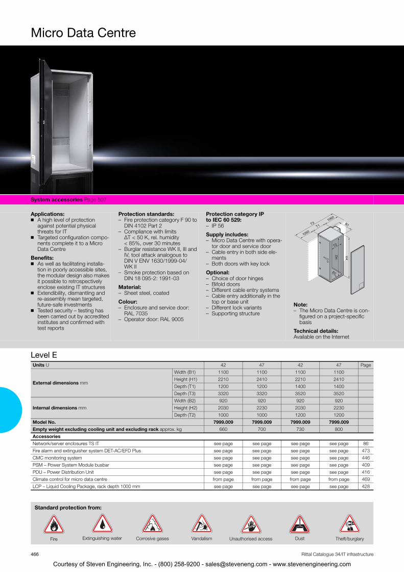
icro Data Centre
MSy
Ap◾
◾
Be◾
◾
◾
LU
stem accessories Page 507
plications:A high level of protection against potential physical threats for ITTargeted configuration compo-nents complete it to a Micro Data Centre
nefits:As well as facilitating installa-tion in poorly accessible sites, the modular design also makes it possible to retrospectively enclose existing IT structures Extendibility, dismantling and re-assembly mean targeted, future-safe investments Tested security – testing has been carried out by accredited institutes and confirmed with test reports
Protection standards:– Fire protection category F 90 to
DIN 4102 Part 2– Compliance with limits
ΔT < 50 K, rel. humidity < 85%, over 30 minutes
– Burglar resistance WK II, III and IV, tool attack analogous to DIN V ENV 1630/1999-04/WK II
– Smoke protection based on DIN 18 095-2: 1991-03
Material:– Sheet steel, coated
Colour:– Enclosure and service door:
RAL 7035– Operator door: RAL 9005
Protection category IP to IEC 60 529: – IP 56
Supply includes:– Micro Data Centre with opera-
tor door and service door– Cable entry in both side ele-
ments– Both doors with key lock
Optional:– Choice of door hinges– Bifold doors– Different cable entry systems– Cable entry additionally in the
top or base unit– Different lock variants– Supporting structure
Note:– The Micro Data Centre is con-
figured on a project-specific basis
Technical details:Available on the Internet
T2
B1
H1
B2
H2
T1
1060
1060
T3
evel E nits U 42 47 42 47 Page
Width (B1) 1100 1100 1100 1100
External dimensions mm Height (H1) 2210 2410 2210 2410Depth (T1) 1200 1200 1400 1400Depth (T3) 3320 3320 3520 3520
Internal dimensions mm Width (B2) 920 920 920 920Height (H2) 2030 2230 2030 2230Depth (T2) 1000 1000 1200 1200
Model No. 7999.009 7999.009 7999.009 7999.009 Empty weight excluding cooling unit and excluding rack approx. kg 660 700 730 800 Accessories Network/server enclosures TS IT see page see page see page see page 86Fire alarm and extinguisher system DET-AC/EFD Plus see page see page see page see page 473CMC monitoring system see page see page see page see page 446PSM – Power System Module busbar see page see page see page see page 409PDU – Power Distribution Unit see page see page see page see page 416Climate control for micro data centre from page from page from page from page 469LCP – Liquid Cooling Package, rack depth 1000 mm see page see page see page see page 428
Standard protection from:
Rittal Catalogue 34/IT infrastructure
Fire Extinguishing water Vandalism Unauthorised access Dust Theft/burglaryCorrosive gases
Courtesy of Steven Engineering, Inc. - (800) 258-9200 - [email protected] - www.stevenengineering.com
466

Micro Data Centre
Sy
ApBaphnecoince
Be◾
◾◾◾◾
Sy
Ap◾
Be◾
◾◾
stem accessories Page 507
plications:sic protection against potential ysical threats for IT compo-nts. Targeted configuration mponents transform the safe
to a complete, compact data ntre.
nefits: TS 8 frame with protection standardsModular assemblyLow weightEasier cable entryFast assembly
Protection standards: – Fire protection F 90 to EN 1363
and based on DIN 4102– Theft protection RC 2 based on
EN 1630– Acrid gas-tightness based on
EN 1634– Protection category IP 56 to
EN 60 529
Material: – Pladur® plate
Colour: – Enclosure and rear door:
RAL 7035– Operator door: RAL 9005
Supply includes: – Safe with integral TS 8 frame– Cable duct in both side ele-
ments– Operator and service door with
swing-lever handle and semi-cylinder
B1
T2
T1
H1
B2
H2
T3
stem accessories Page 507
plications:Basic protection against poten-tial physical threats for IT com-ponents. Targeted configura-tion components complete it to a Micro Data Centre
nefits:Modular layout for installation in hard-to-access locationsLower weight than the Level E Tested security – testing has been carried out by accredited institutes and confirmed with test reports
Protection standards: – Fire protection – fire resistance
class EI 90/F 90 to DIN EN 1363-1: 1999 based on DIN 4102-2: 1977
– Burglar resistance RC 2, tool attack analogous to DIN EN 1630/2011-09/RC 2
– Smoke protection based on DIN EN 18 1634-3: 2005-01
Material:– Sheet steel, coated
Colour:– Enclosure and rear door:
RAL 7035– Operator door: RAL 9005
Protection category IP to IEC 60 529:
Supply includes: – Micro Data Centre with integral
TS 8 frame– Front and rear 482.6 mm (19˝)
level– Adjusted air baffle plates– Every side element is prepared
for one cable entry at the bot-tom and one cable entry at the top
– Operator and service door with swing-lever handle and semi-cylinder
Optional:– Choice of door hinges– Bifold doors– Different cable entry systems– Cable entry additionally in the
top and base element
Note:– The Micro Data Centre is con-
figured on a project-specific basis
B1
T2
T1
H1
B2
H2
T3
– IP 56 – Different lock variants– Supporting structure with fire
protectionTechnical details:Available on the Internet
Level BUnits U 42 47 42 47 Page
External dimensions mm
Width (B1) 1115 1115 1115 1115Height (H1) 2205 2405 2205 2405Depth (T1) 1377 1377 1577 1577Depth (T3) 3274 3274 3474 3474
Internal dimensions mm Width (B2) 905 905 905 905Height (H2) 2000 2200 2000 2200Depth (T2) 1060 1060 1260 1260
Model No. 7999.709 7999.709 7999.709 7999.709Empty weight excluding cooling unit approx. kg 595 630 660 700 AccessoriesFire alarm and extinguisher system DET-AC/EFD Plus see page see page see page see page 473CMC monitoring system see page see page see page see page 446PSM – Power System Module busbar see page see page see page see page 409PDU – Power Distribution Unit see page see page see page see page 416Climate control for micro data centre from page from page from page from page 469LCP – Liquid Cooling Package, rack depth 1000 mm see page see page see page see page 428
Standard protection from:
467al Catalogue 34/IT infrastructure
Fire Extinguishing water Vandalism Unauthorised access Dust Theft/burglaryCorrosive gases
Courtesy of Steven Engineering, Inc. - (800) 258-9200 - [email protected] - www.stevenengineering.com
Ritt

icro Data Centre
MSy
Ap◾
◾
◾
Be◾
◾
◾
stem accessories Page 507
plications: Protection for server and storage applicationsProtection for business-critical dataStorage of personal data, e.g. doctors’ surgeries or tax advi-sors
nefits:Complete system with built-in cooling and 482.6 mm (19˝) rackHigh level of operational and service-friendliness thanks to the two-door systemCompatibility with other infra-structure elements
◾ Tested security – testing has been carried out by accredited institutes and confirmed with test reports
Protection standards: – Fire protection category F 90 to
DIN 4102 Part 2, compliance with limits ΔT < 50 K, rel. humidity < 85 % over 10 minutes
– Burglar protection WK II,tool attack analogous to DIN V ENV 1630/1999-04/WK II
Material:– Sheet steel, coated
Colour:– Enclosure and service door:
RAL 7035– Operator door: RAL 9005
Protection category IP to IEC 60 529: – IP 55
Supply includes:– Security enclosure with operat-
ing and service doors (three-point locking)
– Cable entry in both side ele-ments
– Cooling 2.4 kW designed as a split unit
Technical details:Available on the Internet T1
H1
T2
B2
H2
B1
T3
Level AUnits U 15 PageCooling output W 2400
External dimensions mm
Width (B1) 806Height (H1) 1699Depth (T1) 1270Depth (T3) 2746
Internal dimensions mm Width (B2) 620Height (H2) 827Depth (T2) 1024
Weight excluding internal fittings, including climate control unit approx. kg 360 Model No. Micro data centre with built-in 482.6 mm (19˝) rack 7999.999Model No. Micro data centre without built-in 482.6 mm (19˝) rack 7999.898Accessories482.6 mm (19˝) rack, 15 U, depth 1000 mm 7995.992 Fire alarm and extinguisher system DET-AC/EFD Plus see page 473CMC monitoring system see page 446PDU – Power Distribution Unit see page 416
Rittal Catalogue 34/IT infrastructure
Fire Extinguishing water Vandalism Unauthorised access Dust Theft/burglary
tandard protection from:
Courtesy of Steven Engineering, Inc. - (800) 258-9200 - [email protected] - www.stevenengineering.com
468
S

Micro Data Centre
Sy
◾
◾
◾
◾
stem accessories Page 507 Micro Data Centre Page 466/467
Separate, hermetically sealed internal and external circuits Dust and flue gases are una-ble to ingress The internal and external unit are connected to one another via refrigerant lines and control cables and shielded for fire protection Air routing in the Micro Data Centre is horizontal. Modified air baffle plates ensure tar-geted air routing. By separat-ing the “cold side” from the “hot side”, air short-circuits are avoided, and the efficiency of cooling is enhanced.
◾ Suitable for use in rooms with climate control in the building or adequate ventilation, and low or no noise level require-ments. The evaporator coil is fastened to the side panel on the inside of the Micro Data Centre, and the external device on the service door.
Colour:– RAL 7035
Protection category IPto IEC 60 529: – External circuit IP 54 – Internal circuit IP 24
Supply includes:– Internal unit – External unit– Refrigerant lines– Data and supply lines
� Flexible refrigerant lines inlet/return
� Power supply
� Data cable
� External unit
� Internal unit
1
3
54
2
Compact split cooling solution
469Rittal Catalogue 34/IT infrastructure
Model No. 3126.230 3126.240 Rated operating voltage V, ~, Hz 400/460, 3~, 50/60 400/460, 3~, 50/60
External unitWidth mm 500 500Height mm 1580 1580Depth mm 231 231
Internal unitWidth mm 804 804Height mm 1544 1544Depth mm 100 100
Cooling output 50/60 Hz L35 L35 W 2500/3090 4000/4010 Cooling output 50/60 Hz L35 L50 W 2070/2300 3020/3250 Rated max. current A 3.3/3.5 4.1/4.8Start-up current A 14.2/14.7 15.2/15.8 Pre-fuse A 6.3 – 10.0 6.3 – 10.0 Motor circuit-breaker ◾ ◾ Power consumption Pel 50/60 Hz L35 L35 W 1275/1615 1620/2125 Power consumption Pel 50/60 Hz L35 L50 W 1525/1920 1825/2835 Refrigeration factor ɛ = QK/Pel L35 L35 2.0 2.5 Refrigerant g R134a,1500 R134a, 2900 Permissible operating pressure (p. max.) bar 28 25 Temperature range +20°C…+55°C +20°C…+55°C Setting range +20°C…+55°C +20°C…+55°C Noise level dB (A) < 70 < 72
Weight kg External unit 65 65 Internal unit 70 70
Temperature control Comfort controller (factory setting +25°C)
Courtesy of Steven Engineering, Inc. - (800) 258-9200 - [email protected] - www.stevenengineering.com

icro Data Centre
MSy
◾
◾
stem accessories Page 507 Micro Data Centre Page 466/467
The internal circuit of the cool-ing unit is secured to the side panel inside the Micro Data Centre. The external unit is positioned outside of the building. The internal and external units are connected to one another via refrigerant lines and control cables. The hot air from the servers is drawn in at the rear, and the cooled air is expelled in front of the 482.6 mm (19˝) level. The waste heat is routed directly to the outside. As a result, room ventilation or air-conditioning is not necessary.
Colour: – RAL 7035
Supply includes:– Internal unit – External unit– Refrigerant lines– Data and supply cables
� Copper pipe inlet/return
� Power supply
� Data cable
� External unit
� Internal unit
1
3
5
4 5
4
4
2
Outdoor split cooling solutionModel No. 7999.963 7999.965 7999.964 7999.966Redundancy – – ◾ ◾ Rated operating voltage V, ~, Hz 230, 50, 1~ 400, 50, 3~ 230, 50, 1~ (2 x) 400, 50, 3~ (2 x)
External unitWidth mm 795 900 795 900Height mm 610 680 610 680Depth mm 290 340 260 340
Internal unitWidth mm 1020 1020 1020 1020Height mm 1500 1500 1500 1500Depth mm 100 100 100 100
Cooling output 50/60 Hz L35 L35 W 2400 5000 2400 5000 Rated current per unit, max. A 3.8 4.1 3.8 4.1Start-up current per unit A 19.5 35 19.5 35Pre-fuse A 16 3 x 16 16 (2 x) 3 x 16 (2 x)Refrigerant R410a R410a R410a R410aTemperature range -15°C…+35°C -15°C…+35°C -15°C…+35°C -15°C…+35°C
Weight kg External unit 38 74 2 x 38 2 x 74Internal unit 59 59 63 66
AccessoriesRefrigerant line incl. electric control cable for 2400 W, length 20 m 7999.961 – 7999.961 –
Refrigerant line incl. electric control cable for 5000 W, length 20 m – 7999.962 – 7999.962
470 Rittal Catalogue 34/IT infrastructure
Courtesy of Steven Engineering, Inc. - (800) 258-9200 - [email protected] - www.stevenengineering.com

Micro Data Centre
Sy
◾
Sy
◾
◾
C–
Su––
stem accessories Page XXX
The cooling unit with inverter technology allows targeted speed control of the compres-sor. The refrigerant volume is regulated via the electronic expansion valve. Adaptation to cooling requirements facili-tates energy savings of up to 40 %. The cold air is expelled in front of the 482.6 mm (19˝) level by the internal unit (evap-orator coil), while the hot air is drawn in at the rear.
� Copper pipe inlet/return
� Power supply
� Data cable
� Control box
� Operating unit
Changeover box
External unit
� Internal unit
stem accessories Page 507 Micro Data Centre Page 466/467
Demand-based speed control of the compressor. The refrig-erant volume is regulated via the electronic expansion valve. Energy savings of up to 40%. The cold air is expelled in front of the 482.6 mm (19˝) level by the internal unit (evaporator coil), while the hot air is drawn in at the rear.
olour:RAL 7035
pply includes:Internal unit External unit
– Refrigerant lines– Data and supply cables
� Copper pipe inlet/return
� Power supply
� Data cable
� Control box
� Operating unit
Changeover box
External unit
� Internal unit
1
3
8
7
2
4
5
6
7
471Rittal Catalogue 34/IT infrastructure
Split outdoor cooling solution with inverter technologyModel No. 7999.991 7999.992Redundancy – ◾ Rated operating voltage V, ~, Hz 230, 50, 1~ 230, 50, 1~ (2 x)
External unitWidth mm 900 900Height mm 795 795Depth mm 320 320 (2 x)
Internal unitWidth mm 804 804Height mm 1544 1544Depth mm 100 100
Cooling output 50 Hz L181) L35 W 7850 7850 Cooling output 50 Hz L18 L43 W 7030 7030 Rated max. current A 13.9 13.9 (2 x)Start-up current A 36 36 (2 x)Pre-fuse A 25 25 (2 x)Refrigerant R410a R410aTemperature range -15°C…+43°C -15°C…+43°C Noise level dB (A) 48…49 48…49
Weight kg External unit 63 63 (2 x)Internal unit 70 70 (2 x)
Also requiredHeat exchanger (evaporator coil) 3126.270 3126.2702)
1) Server inlet temperature 2) 2 heat exchangers are required
Courtesy of Steven Engineering, Inc. - (800) 258-9200 - [email protected] - www.stevenengineering.com

ata Centre Container
DSy
Fi–
D––
–
R––
–
stem accessories Page 507
re protection:Fire protection, internal panels: F30, optionally F90 based on DIN 4102/EN1363, compo-nent-tested
uct system:Type: Hard duct DN200Dimensions of packing space: 120 x 120 mmProtected cable/tube entries
aised floor:Optimised load distributionEquipped with cable/tube routingVariable ventilation panels with DFC
Climate control: – Customised climate control
variants – Targeted cooling via aisle con-
tainment – Energy-efficient DFC cooling
(direct free cooling), with no additional external units
– Powerful LCP cooling (liquid cooling package), with minimal space requirements
Power distribution:– Infeed: CEE connector 125 A,
3-phase/N/PE, 400 V/50 Hz– Busbar system for rack-based
power distribution
Customised solutions:– Interlinked containers, other
climate control variants
Optional: – Up to seven TS IT racks with
power supply– Fire alarm/extinguisher system
(Novec 1230)– Access systems, access door
(keyboard, code card) – Monitoring and management
(CMC, RiZone) for monitoring alarm, maintenance messages and customer-specific para-meters
Note:– Standard range of models with
pre-configured data centre types
– The Data Centre Container is configured on a project-specific basis
Technical details: Available on the Internet
Photo shows a configuration example with equipment not included in the scope of supply
Type 1 2 3 4 5 6 7 8 9
472 Rittal Catalogue 34/IT infrastructure
Width mm 3000Height mm 3250Depth mm 6058 8000 10000 11500 6058 8000 10000 11500 9500Useful area m2 15.2 20.4 25.7 29.7 15.2 20.4 25.7 29.7 20.4Model No. 7857.998Climate control, Direct Free Cooling/Liquid Cooling Packages DFC DFC DFC DFC LCP LCP LCP LCP LCPMax. cooling output kW 20 20 50 50 20 40 80 100 40Redundancy cooling n+1 n+1 n+1 n+1 n+1 n+1 n+1 n+1 n+1 Heavy-duty raised floor ◾ ◾ ◾ ◾ ◾ ◾ ◾ ◾ ◾ Plug-and-play power distribution ◾ ◾ ◾ ◾ ◾ ◾ ◾ ◾ ◾ Hard ducts DN200 3 3 4 4 4 5 5 5 5Security door, resistance class 2 ◾ ◾ ◾ ◾ ◾ ◾ ◾ ◾ ◾ Optional fittings
DET-AC XL fire alarm/extinguisher system ◾ ◾ ◾ ◾ ◽ ◽ ◽ ◽ ◽ UPS (uninterruptible power supply) ◽ ◽ ◽ ◽ ◽ ◽ ◽ ◽ ◽ Max. no. of racks 42 U (600 mm wide) without UPS 6 9 10 12 6 8 11 13 8Max. no. of racks 42 U (800 mm wide) without UPS 4 6 7 9 4 6 8 9 6
Higher racks (47 U) ◽ ◽ ◽ ◽ ◽ ◽ ◽ ◽ ◽ Rack power supply ◽ ◽ ◽ ◽ ◽ ◽ ◽ ◽ ◽ Monitoring package (CMC III) ◽ ◽ ◽ ◽ ◽ ◽ ◽ ◽ ◽ RiZone package ◽ ◽ ◽ ◽ ◽ ◽ ◽ ◽ ◽ Security door, resistance class 3 ◽ ◽ ◽ ◽ ◽ ◽ ◽ ◽ ◽ Additional hard ducts for cable/pipe entry ◽ ◽ ◽ ◽ ◽ ◽ ◽ ◽ ◽ Metal sun shade ◽ ◽ ◽ ◽ ◽ ◽ ◽ ◽ ◽
� Standard ◽ Option
Courtesy of Steven Engineering, Inc. - (800) 258-9200 - [email protected] - www.stevenengineering.com

Fire alarm and extinguisher system DET-AC/EFD Plus
Sy
Be◾◾
◾
C–
stem accessories Page 507 Network/server enclosures Page 90
nefits: Early fire detection Automatic extinguishing – Innovative extinguisher gas
NOVEC 1230 – Eco-friendly – Uncritical for IT components 482.6 mm (19˝) rack mount with just 1 U
olour: RAL 7035
DET-AC PlusCompact fire alarm and active extinguisher system with smoke extraction system, built into one height unit. The detection system is identical to that used in the EFD Plus system. Fire extinguishing with the extinguisher gas NOVEC 1230 is automatically activated when a main alarm is triggered. With the extinguisher gas supply provided, a volume of up to 3 m3 can be extinguished. The collec-tive fault signal and the alarms may be forwarded to the CMC.
DET-AC Plus slaveIn conjunction with the DET-AC Plus slave system, up to five bayed enclosures may be extin-guished. In addition to the DET-AC Plus unit, each additional enclosure requires a DET-AC Plus slave unit, which contains the extinguisher gas for one enclo-sure. The pipework from the DET-AC Plus system is laid in all enclosures to facilitate detection.
EFD PlusCompact early fire detection sys-tem with active smoke extraction system. The integral fan continuously extracts the air from the enclo-sure, and passes it over two smoke detectors. The first smoke detector is extremely sensitive and triggers a pre-alarm. The second smoke detector trig-gers the main alarm.
Photo shows a configuration example with equipment not included in the scope of supply.
Fire alarm and extinguisher system DET-AC Plus
Additional unitDET-AC Plus slave
Early fire detection system EFD Plus
Width mm 482.6 (19˝ rack mount) 482.6 (19˝ rack mount) 482.6 (19˝ rack mount) Height mm 44 (1 U) 44 (1 U) 44 (1 U) Depth mm 640 570 500Weight, approx. kg 15 12 8Model No. 7338.120 7338.320 7338.220Protection category IP to IEC 60 529 IP 20 IP 20 IP 20Ambient temperature (operation) +10°C…+35°C +10°C…+35°C +10°C…+35°C Battery storage -15°C…+40°C -15°C…+40°C -15°C…+40°CRated operating voltage V, ~, Hz 100/240, 1~, 50/60 24 (DC) 100/240, 1~, 50/60 Uninterruptible mains electricity operation 2 x 12 V; 2.2 A/approx. 4 h 2 x 12 V; 2.2 A/approx. 4 h 2 x 12 V; 2.2 A/approx. 4 h
Connections 3 x RJ 12, alternatively 3 x relays, max. 24 V DC/0.5 A
3 x RJ 12, alternatively 3 x relays, max. 24 V DC/0.5 A
3 x RJ 12, alternatively 3 x relays, max. 24 V DC/0.5 A
Sensors 2 different scattered-light sensors – 2 different scattered-light sensors Display LCD display with plain text information – LCD display with plain text informationNo. of slave modules max. 4 – max. 5No. of monitored enclosures max. 5 – max. 5Extinguisher gas NOVEC 1230 NOVEC 1230 – Extinguisher gas fill volume kg 3.2 3.2 – Admissible max. protection volume m3 3 3 – Also required Pipe kit 7338.130 7338.130 7338.130 Page RJ 12 cable for alarm relaying to CMC,packs of 2 7320.8141) 7320.8141) 7320.8141) 458
Access sensors 7320.530 7320.530 – 455 Depth-variable slide rails – – 5501.480 687
1) 2 packs are required.
473Rittal Catalogue 34/IT infrastructure
Courtesy of Steven Engineering, Inc. - (800) 258-9200 - [email protected] - www.stevenengineering.com

ecurity rooms
SC
Sy
ThThtioteunsytio
stem accessories Page 507 Network/server enclosures Page 90
e basic protection room e basic protection room provides a high-quality, system-tested solu-n. It is an optimum, modular room-within-a-room solution for pro-cting IT/infrastructure components such as extinguisher systems, interruptible power supplies and climate control. The flexible modular stem means that it can be extended whilst the IT systems are opera-nal.
Benefits: ◾ System-tested protection levels◾ Multi-functional risk coverage◾ Dust- and noise-reduced installation◾ Dismantling and reassembly plus extendibility = investment security◾ May be adapted for use in other room systems, such as the
High Availability room
riterion Standards
System testingTesting the following standards as a complete system or construction
Fire protection
ECB·S certification to EN 1047-2, 50 K temperature increase and 85% rel. humidity for up to 24 hours (reheating period), flame impingement time 60 minutes
50 K temperature increase and 85% rel. humidity without reheating period, flame impingement time 30 minutesF 120 to DIN 4102F 90 to DIN 4102
Corrosive fire gases Acrid gas-tightness based on DIN 18 095 Falling debris Impact test at 200 kg
WaterIP X6 to IEC 60 529Protection from standing water
Dust IP 5X to IEC 60 529
Unauthorised accessWK IV to DIN V ENV 1630, door system onlyWK III to DIN V ENV 1630, or DIN V 18 103 (ET2)WK II to DIN V ENV 1630
Explosion Detonation testEMC Protection from high-frequency irradiation and radiation
System-tested structures are tested as a complete construction, comprising the cell structure and built-in modules such as doors, cable shields or ventilation units. By contrast, generic component testing only refers to individual parts.
Conventional construction methods refer to room structures made of plasterboard, concrete and other standard construction materials which do not offer sufficient protection for data centre applications. Conventional construction methods are generally unsuitable for use as a fire wall and are therefore only subjected to component testing.
474 Rittal Catalogue 34/IT infrastructure
Courtesy of Steven Engineering, Inc. - (800) 258-9200 - [email protected] - www.stevenengineering.com

Security rooms
Sy
ThThce(EThretioan
stem accessories Page 507 Network/server enclosures Page 90
e High Availability room e High Availability room offers maximum physical protection for data ntres and IT system locations. The system was certified by ECB uropean Certification Body GmbH) to ECB·S regulations. is certification confirms that the High Availability room meets the quirements of EN 1047-2 without restriction. Moreover, the construc-n of the security room is subject to continuous quality monitoring by independent agent.
Benefits: ◾ System-tested High Availability protection◾ Multi-functional risk coverage◾ Dust- and noise-reduced installation◾ Dismantling and reassembly plus extendibility = investment security◾ ECB·S certification◾ Independent quality monitoring◾ May be adapted for use in other room systems, such as the basic
protection room
Basic protection room High Availability room
◾ ◾
– ◾
◽ –– ◾ ◾ –◾ ◾ ◾ ◾ ◾ ◾ – ◾ ◾ ◾ – ◾ ◽ ◾ ◾ –– ◾ ◾ ◾
◾ Standard ◽ Optional
475Rittal Catalogue 34/IT infrastructure
Courtesy of Steven Engineering, Inc. - (800) 258-9200 - [email protected] - www.stevenengineering.com