rivertrace engineering ltd - recovered · pdf filerivertrace engineering ltd 109080...
TRANSCRIPT

RIVERTRACE
ENGINEERING LTD
109080
INSTRUCTION MANUAL
BILGE OIL ALARM
UNIT P, KINGSFIELD BUSINESS CENTRE
PHILANTHROPIC ROAD, REDHILL,
SURREY, UNITED KINGDOM RH1 4DP
TELEPHONE: +44(0)1737 775500 FAX: +44(0)1737 775501
WEB: http://www.rivertrace.com EMAIL: [email protected]

SMART CELL - BILGE - Instruction Manual Doc. 109080 Rev. S 21.10.11 ECN 4102
RIVERTRACE ENGINEERING LIMITED Page 2 of 34
Section 1 Introduction
1.1 Important Notes 3
1.2 SMART CELL - BILGE Overview 4
1.3 Specification Listing 5 - 6
Section 2 Installation
2.1 Construction details 7
2.2 Mounting 8
2.3 Pipe work and Connections 9
2.4 Electrical Connections 10 - 13
Section 3 Commissioning
3.1 Piping 14
3.2 Electrical 14
3.3 Functional testing 14
3.4 Throttle 14
Section 4 Operating Instructions
4.1 Getting Started 15 - 16
4.2 Clean Water Calibration 17
4.3 Set Alarm Points 18
4.4 Set Alarm Delays 19
4.5 Set Analogue out 20
4.6 View IMO Data 21
4.7 Diagnostics & Clean Water Flushing 22
4.8 Test Procedure 23
4.9 Monitor Verification 23
Section 5 Maintenance and Spares
5.1 Maintenance (weekly) 24
5.2 Maintenance (Yearly) 24
5.3 Maintenance (5 Years) 24
5.4 Spares 25
Section 6 Trouble Shooting & Contact
6.1 Trouble Shooting Guide 26 - 27
6.2 Faultfinding 28
6.3 Additional Features and Functions 29
6.4 Tech Support registration 29
Annexe Certificates
EC MED & USCG Certificates 30 – 34
SMART CELL - BILGE - Instruction Manual Doc. 109080 Rev. S 21.10.11 ECN 4102
RIVERTRACE ENGINEERING LIMITED Page 3 of 34
Section 1
Introduction
1.1 Important Notes
� All National or local codes of practice or regulations must be observed and, where
applicable, are deemed to take precedence over any directive or information contained in
this manual.
� This equipment must be installed and operated in strict accordance with the instructions
contained in this manual. Failure to do so will impair the protection provided.
� Installation and retro fitting of parts listed in Section 5.3 must be undertaken by a competent
and suitably skilled person.
� Servicing, other than replacement of spares, must be undertaken by an RTE approved
service centre.
� The equipment must be provided with a sound electrical earth connection.
� The unit must be isolated from the electrical supply before any maintenance of the
equipment is attempted.
� Hazardous voltages are present within the monitor enclosure and solenoid valve assembly.
� It is essential that maintenance is carried out as described in Section 5. Failure to do this will
impair the functionality of the equipment and could lead to permanent damage to the
monitor.
� The SMART CELL enclosure must not be opened. If opened a cell breach error will be
displayed on the screen (this error cannot be reset) and the “VOID” tamper proof labels on
either side of the enclosure lid will be destroyed. Forcing the throttle to its extents will also
damage the cell and if unscrewed will distort the cell lid thereby causing a cell breach error.

SMART CELL - BILGE - Instruction Manual Doc. 109080 Rev. S 21.10.11 ECN 4102
RIVERTRACE ENGINEERING LIMITED Page 4 of 34
1.2 SMART CELL - BILGE Overview
The SMART CELL - BILGE Monitor has been designed specifically for use in conjunction with
15ppm oily-water separator units. It has a specification and performance which meets the
requirements of the International Maritime Organisation specifications for Bilge Alarm Units
contained in Resolution MEPC 107 (49).
Analysis of the oily water sample is undertaken by a unique detector array arrangement. A
narrow beam of light is emitted across a glass cell tube which the oily water sample passes
through. Light scattered and transmitted is detected across the array and passed through a
complex oil content calculation algorithm. The resulting oil content is then displayed on the LCD
screen.
Two oil alarm relays and a 0-20mA / 4-20mA output are provided to control the overboard
discharge and to view / record oil content levels remotely.
To meet the new requirements of MEPC 107(49) an on board flash memory, Real time clock,
dual switch input and clean water / sample selection valve are fitted. These are described in
more detail in the operating instructions (Section 4).

SMART CELL - BILGE - Instruction Manual Doc. 109080 Rev. S 21.10.11 ECN 4102
RIVERTRACE ENGINEERING LIMITED Page 5 of 34
1.3 Specification Listing
Measurement
Oil types: Fuel Oil, Diesel and Mixture C (IMO defined)
Clean water calibration: +/- 2ppm of factory set values
Oil range: 0 - 30 ppm (trend to 40) all types
Resolution: 0.1 ppm
Accuracy oil + solids : +/- 5ppm up to 30 ppm
Solids discrimination: 100ppm Iron Oxide in 10 ppm Diesel
Response time: < 5 sec (oil reading)
Alarms
Oil alarm 1 setpoint: 1 – 15 ppm user adjustable
Oil alarm 2 setpoint: 1 - 15 ppm user adjustable
Oil alarm 1 delay: 0 – 5 seconds user adjustable (For Overboard Valve)
Oil alarm 2 delay: 0 – 600 seconds user adjustable in 10 sec increments
(For Annunciation only)
Alarm hysteresis: 0.5 ppm
Alarm contacts: 2 SP Alarm Relays 10A @ 250VAC (NC in alarm)
User Interface
LCD display: 4 x 16 alphanumeric back lit LCD display
Control: 3 button keypad
Input / Output
Analogue output: Loop powered 4-20mA / 0 - 20mA 24V
Communications: RS232 - output
Cable terminals: Accept cores of 2.5mm² (HV) and 1.5mm² (LV)
Cable glands: 4 x to accept cable diameters 10 – 14mm dia.
Switch inputs: 2 x switch inputs for separator & flow status
Data Storage and Retrieval
Calibration data storage: Stored on board microcontroller in Smart Cell
IMO required data: Stored in Control enclosure (SMART CELL may be
changed with data remaining on board)
IMO required data retrieval: Via LCD display or RS 232 communication link

SMART CELL - BILGE - Instruction Manual Doc. 109080 Rev. S 21.10.11 ECN 4102
RIVERTRACE ENGINEERING LIMITED Page 6 of 34
Environmental & Sample
Ambient humidity: 90%RH Max @ 55°C
Ambient temperature: 0°C - +60°C
Sample / clean water temperature: +1°C - +60°C
Sample / clean water flow rate: 0.5 - 4.0 litres / min
Sample / clean water pressure: 0.1 bar - 10 bar
Sample / clean water select: 3 way universal solenoid valve
Sample pipe fittings: ¼ inch BSPP
Inclination 25° in any plane from normal mounting
System and Supply
Supply voltage: 115 or 230V AC, 50 – 60Hz (24VAC available)
Supply voltage Consumption: < 50 VA including solenoid valve
Supply voltage tolerance: +/- 15%
Other supply tolerance: +/- 10%
Projected life: > 50,000 hrs
Protection class: IP 65
Approvals: EU MED (GL) + USCG to IMO MEPC 107(49)
Construction and other Criteria.
Security: Protection of all calibration dependent items plus
software lock
Auto clean (optional) : User set 1 – 360 min (if fitted)
Manual clean: Fitted as standard
Weight: 3.2 Kg
Factory Default Settings.
Alarm 1: 15 ppm
Alarm 1 delay period: 5 seconds
Alarm 2: 15 ppm
Alarm 2 delay period: 70 seconds
Current loop: 4-20mA
Autoclean: Not set
Flowswitch: Not set

SMART CELL - BILGE - Instruction Manual Doc. 109080 Rev. S 21.10.11 ECN 4102
RIVERTRACE ENGINEERING LIMITED Page 7 of 34
Section 2
Installation
2.1 Construction Details
The SMART CELL - BILGE Monitor is split into two logical modules. The display / control module
(2) (left) contains the membrane keypad, LCD display and the Smart Bilge Control PCB.
Contained on this PCB are all the control and data storage associated electronics in addition to
all the customer terminations which can be accessed via the cable glands(5). This PCB links a
5 volt supply and RS485 communications to the Cell electronics via a 4 wire interface cable.
The SMART CELL (1), contains the optoelectronics and mechanics used in the calculation of the
sample oil content. UNDER NO CIRCUMSTANCE IS THIS ENCLOSURE TO BE OPENED. Sample (7)
and clean water (8) lines are connected to the solenoid valve to allow automatic selection of
clean water for clean water calibration and diagnostics. Sample/Clean water is exhausted
from the monitor via the outlet (6) after passing through the measuring sensor. A manual cell
clean unit (3) is provided which must be used in accordance with the maintenance
requirements in Section 5. The throttle (9) can be used to increase or decrease the back
pressure in the cell. This is especially useful if air is present in the sample.
Fig 2.1
Construction details

SMART CELL - BILGE - Instruction Manual Doc. 109080 Rev. S 21.10.11 ECN 4102
RIVERTRACE ENGINEERING LIMITED Page 8 of 34
2.2 Mounting Details
The SMART CELL - BILGE monitor should be located on or in close proximity to the oily-water
separator to minimise response delays. Under no circumstances should the distance between
the monitor and the separator exceed a distance that would result in a response time of more
than 20 seconds and breaching IMO regulations.
Mounting
Mount the SMART CELL - BILGE by means of 4 x M6 bolts on to a rigid vertical surface and
preferably with the display panel of the monitor at operator eye level.
Fig 2.2
Mounting Details

SMART CELL - BILGE - Instruction Manual Doc. 109080 Rev. S 21.10.11 ECN 4102
RIVERTRACE ENGINEERING LIMITED Page 9 of 34
2.3 Pipe Work and Connections
Fig 2.3 Shows all pipe fittings required for Sample In, Clean Water In and Sample Out.
All inlet connections are ¼”BSPP. The outlet from the measuring cell is a 6mm OD push in fitting.
The monitor is shipped with an adaptor that can change the outlet from 6mm OD push-in to
either 6mm pipe compression fitting or ¼” BSPP. You should ensure that the pipework between
the separator sample point and the monitor is a single pipe and does not contain any isolation
valves. You can use either 6 or 8mm pipework and 10mm pipework if the pipe length between
the separator sample point and the monitor is no more than 2 metres.
Fig 2.3
Pipe Fittings
Item No. Description
1 Sample Inlet 1/4 inch BSPP fitting
2 Clean Water Inlet 1/4 inch BSPP fitting
3 Sample Outlet 1/4 inch BSPP fitting

SMART CELL - BILGE - Instruction Manual Doc. 109080 Rev. S 21.10.11 ECN 4102
RIVERTRACE ENGINEERING LIMITED Page 10 of 34
2.4 Electrical Connections
Please read the following points before attempting any electrical work.
� Ensure all cabling is volt free and isolated.
� This unit must be connected to the mains supply via a suitably rated double pole (3mm
contact gap), 2 Amp fused, isolator unless such fusing/isolation is provided by associated
equipment. Isolator should be clearly marked as to function.
� Cable gland entries can accept cables from 10 to 14 mm diameter and terminal blocks will
accept cable cores of 2.5mm2 (mains / Alarm contacts ) and 1.5 mm2 ( terminals less than
48 V ) . Cables carrying hazardous voltages must be at least 0.5 mm2 csa.
� When terminating mains cabling at monitor and electrical source, the earth conductor must
be made longer than the live and neutral conductors.
User terminations are located by removing the lid from the SMART Display/Control module via
the four screws. A protection plate is situated above the terminals which must be removed via
4 M3 screws.
Fig 2.4.1
User Terminations
WARNING: Hazardous voltages are present In the control enclosure – Ensure
equipment is isolated before proceeding.

SMART CELL - BILGE - Instruction Manual Doc. 109080 Rev. S 21.10.11 ECN 4102
RIVERTRACE ENGINEERING LIMITED Page 11 of 34
Table 2.4.2
User Terminal Connections
Terminal Terminal description Terminal block description Max ratings
J1 - L Live in 24/115/230 V AC
Customer Supply Mains input
from suitably rated Isolator 250V AC, 40 VA max. J1 - E Earth
J1 - N Neutral in 24/115/230 V AC
J2 - L Live 24/115/230 V AC Auto clean control. Note:
wiring (if present) to this
terminal is not to be altered.
250V AC , 500mA. J2 - E Earth
J2 - N Neutral 24/115/230 V AC
J3 - L Live 24/115/230 V AC Sample clean control. Note:
wiring to this terminal is not to
be altered.
250V AC, 500mA. J3 - E Earth
J3 - N Neutral 24/115/230 V AC
J4 - 1 Common Alarm 1 relay contacts,
normally closed in power down
and alarm active states.
(Overboard Valve Control)
250V AC/DC, 10A. J4 - 2 Normally closed contact
J4 - 3 Normally open contact
J5 - 1 Common Alarm 2 relay contacts,
normally closed in power down
and alarm active states.
(Alarm Annunciation Only)
250V AC/DC, 10A. J5 - 2 Normally closed contact
J5 - 3 Normally open contact
J7 - 1 5V DC from PCB
Back-flush Switch Input 2 5V DC 20mA J7 - 2 Switch In
J8 - 1 +24V DC 4-20mA Connection
0-20mA Connection 24V DC 20mA
J8 - 2 0V
J9 - 1 5V DC from PCB Separator Status Switch Input 1 5V DC 20mA
J9 - 2 Switch In
J11 - 1 Tx
RS232 Connection +/-12V DC 10mA J11 - 2 GND
J11 - 3 Rx
Precise wiring details will vary dependent upon the control system to be employed but Alarm
relay 1 must be used for control of the overboard discharge valve and Alarm relay 2 for alarm
annunciation only. The separator status switch input should be connected to a suitable volt-free
contact in the separator. A separate screened cable should be used for this connection.

SMART CELL - BILGE - Instruction Manual Doc. 109080 Rev. S 21.10.11 ECN 4102
RIVERTRACE ENGINEERING LIMITED Page 12 of 34
Fig 2.4.3
User Wiring Connections
L E N L E N L E N 1 2 3 1 2 3
J1 J2 J3 J4 J5
Mains Input Overboard Discharge Valve
Smart Bilge Electrical Connections (provided supply voltage is the same for both Smart Bilge and Overboard Discharge valve)
To Engine Room Alarm
L E N L E N L E N 1 2 3 1 2 3
Mains Input
Overboard Discharge Valve
To Engine Room Alarm
Return to Bilge Valve
J1 J2 J3 J4 J5
Smart Bilge Electrical Connections (if there is a separate discharge and return to bilge valve)

SMART CELL - BILGE - Instruction Manual Doc. 109080 Rev. S 21.10.11 ECN 4102
RIVERTRACE ENGINEERING LIMITED Page 13 of 34
Smart Bilge Electrical connection for separator status switch
If the separator does not have a “Separator Status” volt-free contact then a suitable volt-free
contact will have to be wired in parallel with the motor contactor for the separator pump. In all
cases the wiring between the volt-free contact and the separator status input SW1 on the bilge
monitor should be a screened cable.

SMART CELL - BILGE - Instruction Manual Doc. 109080 Rev. S 21.10.11 ECN 4102
RIVERTRACE ENGINEERING LIMITED Page 14 of 34
Section 3
Commissioning
3.1 Piping
� Check all piping for leaks and rectify where appropriate
� Ensure all piping and fittings conform to specifications set in Section 2.3.
3.2 Electrical
� Check that correctly rated isolator is connected to the mains input (see Section 2.4.).
� Check the SMART CELL - BILGE is correctly earthed.
� Check all cabling conforms to specifications set out in Table 2.4.2
3.3 Functional testing
� Follow section 4 to start up and run clean water calibration.
� Follow section 6 for trouble shooting should any errors/spurious readings result.
3.4 Throttle
The throttle is used to regulate the flow through the measuring cell and to provide backpressure
to decrease any aeration in the sample flowing from the separator.
The throttle should not be forced beyond its end stops – if rotated clockwise beyond its stop it is
possible to strip its thread thereby causing the cell to leak. If the throttle is rotated anticlockwise
beyond its stop then it is possible to distort the cell case lid which in turn will activate a cell
breach error. This will require intervention by RTE
� IF you experience fluctuating ppm readings then firstly try rotating the throttle clockwise to increase
the backpressure. Monitor the flow from the cell. You should ensure that at the flow rate does not fall
below 0.5 litres/min.

SMART CELL - BILGE - Instruction Manual Doc. 109080 Rev. S 21.10.11 ECN 4102
RIVERTRACE ENGINEERING LIMITED Page 15 of 34
Section 4
Operating instructions
4.1 Getting Started
The SMART CELL - BILGE is controlled and set up by the user interface on the Display/Control
Module. Use the diagram in Fig 4.1.1 to become familiar with the controls,
Fig 4.1.1
User interface
4 x 16 Alphanumeric LCD
Display
Red user interface Keys
ENTER, UP and DOWN

SMART CELL - BILGE - Instruction Manual Doc. 109080 Rev. S 21.10.11 ECN 4102
RIVERTRACE ENGINEERING LIMITED Page 16 of 34
Fig 4.1.2
Screen Shot – Start Screen
On power up the user will be presented with a
screen as shown in Fig 4.1.2 which shows that the
monitor is in its start up sequence. The screen will
show “Initialising” and will show a counter that will
decrement from 20 seconds to 0 seconds before
changing to the Main Information screen. During
this period the alarms will be activated.
After initialisation the user will be presented with a screen as shown in Fig 4.1.3.
� At the top of the display the user will see the oil concentration in Parts Per Million (PPM).
� The status of the two oil alarms will be displayed.
� The date and time is displayed. (Time is set to GMT/UTC and can only be adjusted by RTE
approved engineer).
� If either of the alarm set points is passed the LCD backlight will flash. Fig 4.1.3
Screen Shot - Main Information Screen
To interrogate the SMART CELL - BILGE Monitor settings the user can press any of the Interface
Keys which brings up the Menu Options Screen as shown in Fig 4.1.4
Fig 4.1.4
Screen Shot - Menu Screen Options
Use the DOWN and UP Keys to view all the Menu
options. Press ENTER on any option to select or on
Escape to return to main information screen.
Alarm 1 state
Alarm 2 state
Shows Oil
Concentration
in PPM
Date & Time
Display
SMART CELL - BILGE - Instruction Manual Doc. 109080 Rev. S 21.10.11 ECN 4102
RIVERTRACE ENGINEERING LIMITED Page 17 of 34
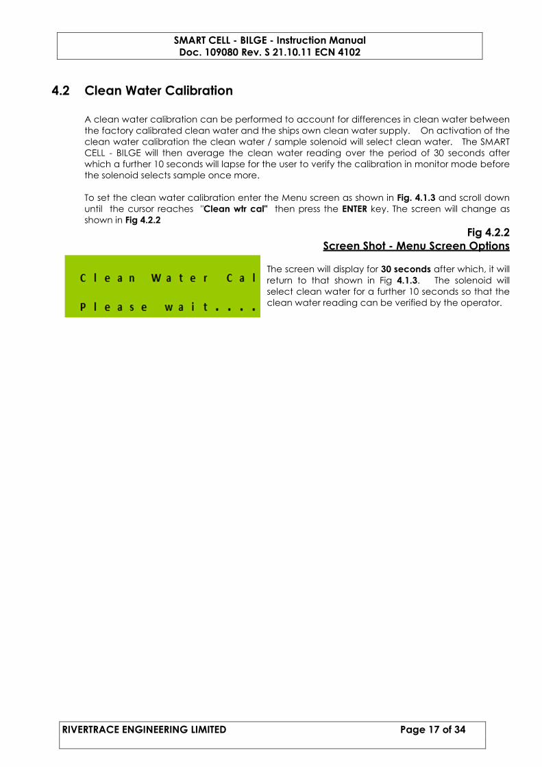
4.2 Clean Water Calibration
A clean water calibration can be performed to account for differences in clean water between
the factory calibrated clean water and the ships own clean water supply. On activation of the
clean water calibration the clean water / sample solenoid will select clean water. The SMART
CELL - BILGE will then average the clean water reading over the period of 30 seconds after
which a further 10 seconds will lapse for the user to verify the calibration in monitor mode before
the solenoid selects sample once more.
To set the clean water calibration enter the Menu screen as shown in Fig. 4.1.3 and scroll down
until the cursor reaches "Clean wtr cal" then press the ENTER key. The screen will change as
shown in Fig 4.2.2
Fig 4.2.2
Screen Shot - Menu Screen Options
The screen will display for 30 seconds after which, it will
return to that shown in Fig 4.1.3. The solenoid will
select clean water for a further 10 seconds so that the
clean water reading can be verified by the operator.

SMART CELL - BILGE - Instruction Manual Doc. 109080 Rev. S 21.10.11 ECN 4102
RIVERTRACE ENGINEERING LIMITED Page 18 of 34
4.3 Set Alarm Points
The SMART CELL - BILGE Monitor has two independent oil alarm contacts for user termination.
These can be set by the user to operate when the displayed Oil content reaches the required
Parts per Million (PPM) settings.
Note: The alarms have a 0.5 ppm hysteresis included to prevent relay chatter. e.g if an alarm is
set at 15 ppm and the oil concentration exceeds 15 ppm, the alarm will be activated. The
alarm will not deactivate until the oil concentration drops below 14.5 ppm.
To set the required Alarm points enter the Menu screen as shown in Fig. 4.1.3 and scroll down
until the cursor reaches "Set alarm point" then press the ENTER key. The screen will change as
shown in Fig 4.3.1.
Fig 4.3.1
Screen Shot - Alarm Set Options
Move the cursor to Alarm 1 set by pressing the DOWN
key and then press ENTER. This will bring up the screen
as shown in Fig 4.3.2.
Note: Alarm 1 MUST be used for control of the
overboard discharge valve.
Fig 4.3.2
Screen Shot - Alarm PPM Value
The PPM value can now be set. The range is between
1 & 15. Use the UP or DOWN key to select the required
value. Once the required value has been selected
press the ENTER key. This will bring the screen back to
Fig 4.3.1. Repeat this operation to set the value for
alarm 2. Press the ENTER key 3 times to return to the
main information screen as shown in Fig 4.1.2.

SMART CELL - BILGE - Instruction Manual Doc. 109080 Rev. S 21.10.11 ECN 4102
RIVERTRACE ENGINEERING LIMITED Page 19 of 34
4.4 Set Alarm Delays
Once the alarm points have been set as described in Section 4.3, the alarm delay values can
be entered. The alarm delay can be used so that if the oil concentration rises above the oil
alarm set point for a period exceeding the alarm delay value the alarm relay will activate and
only de-activate once the Oil Concentration has fallen below the Alarm Set Point.
Note: The main information display screen will show if an oil alarm is less or more than the
current oil reading regardless of the alarm delay.
To set the required alarm delays go the menu screen as shown in Fig. 4.1.3 and scroll down until
the "Set alarm delay" then press the ENTER key. The screen will change as shown in Fig 4.4.1
Fig 4.4.1
Screen Shot - Alarm Delay Options
Move the cursor to delay 1 Set by pressing the DOWN
key and then press ENTER. This will bring up the screen
as shown in Fig 4.4.2.
Fig 4.4.2
Screen Shot - Alarm Set Delay Value
Alarm delay 1 value can now be set between 0 & 5
Seconds. Use the UP or DOWN key to select the
required value. Once the required value has been
selected press the ENTER key, this will bring the screen
back to Fig 4.4.1. Repeat this operation to set the
value for delay 2 (range between 0 & 600 Seconds in
10 second increments).
Press the ENTER key 3 times to return to the main
information screen as shown in Fig 4.1.2.
Fig 4.4.3
Screen Shot – Version Info
The Version Info can be used to view the software
version fitted to the Smart Bilge monitor, it will show
both the software version for the microcontroller
module and the measuring cell module.

SMART CELL - BILGE - Instruction Manual Doc. 109080 Rev. S 21.10.11 ECN 4102
RIVERTRACE ENGINEERING LIMITED Page 20 of 34
4.5 Set Analogue Out
The analogue signal output can be set to either 0 – 20 mA or 4 - 20 mA and is scaled from 0 to
30 ppm calculated oil concentration. To set the required analogue signal output go to the
menu screen as shown in Fig. 4.1.3 and scroll down until the "Set analog out" then press the
ENTER key. The screen will change as shown in Fig 4.5.1.
Fig 4.5.1
Screen Shot - Analogue Output Options
Move the cursor using the UP or DOWN key to select
required option. Press the ENTER key twice to return to
the main information screen as shown in Fig 4.1.2.

SMART CELL - BILGE - Instruction Manual Doc. 109080 Rev. S 21.10.11 ECN 4102
RIVERTRACE ENGINEERING LIMITED Page 21 of 34
4.6 View IMO Data
It is required that the date, time, bilge alarm status and separator status is to be recorded for
any change in alarm status or separator status and stored for a minimum of 18 months. This
data is recorded within the Smart Control / Display enclosure, allowing replacement of the
SMART CELL - BILGE whilst ensuring the data remains on board.
The separator status is recorded via the SW1 and SW2 inputs. The following configuration is
used.
SW1 Separator ON/OFF status.
SW2 Separator Back-flush (If fitted)
Note. SW2 will select clean water and activate alarms permanently when closed. To be
connected to Separator backflush control circuit via a potential free contact.
The configuration of the switches must be recorded on board and date stamped.
To view or download the IMO required data go to the Menu screen as shown in Fig. 4.1.3 and
move the cursor down until "View IMO data" then press the ENTER key. The screen will change as
shown in Fig 4.6.1.
Fig 4.6.1
Screen Shot - View IMO Data
Move the cursor to either View IMO data or Dump
IMO data by pressing the DOWN key and then press
ENTER. This will bring up a screen as shown in Fig 4.6.2
or Fig 4.6.3.
Fig 4.6.2
Screen Shot - IMO Data
This screen displays one IMO record at a time. Each
record shows the oil content, Alarm status, switch
input status and time/date of the record. The users
can scroll through the records by pressing the UP and
DOWN keys. When inspection is complete the ENTER
key will exit the user
Fig 4.6.3
Screen Shot - Dump IMO Data
By selecting the dump IMO data command, the
complete IMO required data history is copied and
down loaded to the RS232 port. This can be captured
by purchasing a Smart Bilge download cable with
instructions from Rivertrace Eng, see Section 5.4. The
download data screen will remain displayed until
download is complete.
NOTE: Dump IMO data command will NOT erase any data

SMART CELL - BILGE - Instruction Manual Doc. 109080 Rev. S 21.10.11 ECN 4102
RIVERTRACE ENGINEERING LIMITED Page 22 of 34
4.7 Diagnostics & Clean Water Flushing
To view the diagnostics go to the menu screen as shown in Fig. 4.1.3 and scroll down until the
"Diagnostics" then press the ENTER key. The screen will change as shown in Fig 4.7.1
Fig 4.7.1
Screen Shot - Diagnostics
Move the cursor to either View detectors or View disp
PPM by pressing the DOWN key and then press ENTER.
This will bring up a screen as shown in Fig 4.7.2, Fig
4.7.3 or Fig 4.7.4
Fig 4.7.2
Screen Shot – View detectors
Once in view detectors, the solenoid valve will select
clean water and the screen will display the current
signals present for clean water. The alarm relays will
activate when view detectors is selected. Pressing the
ENTER key will leave the diagnostics screen and set the
valve back to sample.
Fig 4.7.3
Screen Shot – View disp PPM
Once in “view disp PPM”, the solenoid valve will select
clean water and the screen will display the current
calculated ppm for clean water. The alarm relays will
activate when view detectors is selected. Pressing the
ENTER key will leave the diagnostics screen and set
the valve back to sample.
Fig 4.7.4
Screen Shot – Temperature
Once in view Temperature, the temperatures shown is
the flow temperature in deg Celsius. Pressing the
ENTER key will leave the diagnostics screen and set the
valve back to sample.
Clean Water Flushing
During “View disp PPM”, the clean water valve is activated and clean water is allowed to flow
through the monitor. The display will appear as per Fig. 4.7.3 and the ppm reading of the clean
water will be displayed. This reading should be less than 2 ppm. The manualclean plunger
should be used at this time to clean the glass cell tube.

SMART CELL - BILGE - Instruction Manual Doc. 109080 Rev. S 21.10.11 ECN 4102
RIVERTRACE ENGINEERING LIMITED Page 23 of 34
4.8 Test Procedure
The following procedure is to be adopted to test the Smart Cell Bilge Monitor
1. Press and hold the Manualclean in the down position.
2. Confirm that both alarms are activated.
3. A plunger down error will be displayed.
4. Release the Manualclean.
5. The ppm figure on the LCD display will decrement from 40 towards zero.
This assumes that there is water flowing through the measuring cell.
4.9 Monitor Verification
The monitor’s calibration can be checked by using
the Monitor Verification Water Sample Kit. This kit
contains two bottles of verification fluid, one
marked 10 ppm and the other 20 ppm. The user
menu contains a sub menu – Verify Calib. Entering
this menu allows the user to view the ppm value of
the verification fluid being poured into the cell.
Procedure 109993 refers to the above.

SMART CELL - BILGE - Instruction Manual Doc. 109080 Rev. S 21.10.11 ECN 4102
RIVERTRACE ENGINEERING LIMITED Page 24 of 34
Section 5
Maintenance and Spares
5.1 Weekly Maintenance
� Manual clean must be plunged and released 10 times.
� Carry out “Clean Water Calibration” as per Section 4.2
� Confirm Unit reads 0 ppm by following Section 4.7
5.2 Yearly Maintenance
At yearly intervals (or where necessary) the wiper ring on the manual clean assembly should be
replaced. This can be ordered from RTE directly as part no. 109039.
To remove wiper assembly, electrically isolate the monitor. Have some rags available to wipe up
any spills.
Ensure that the separator is switched off and there is no flow through the monitor cell.
Isolate clean water supply and remove manualclean by using the knurled cap to unscrew it.
Pull the manualclean from the cell in a vertical motion and wipe with a rag. Locate the wiper
and prise off with a small flat bladed screwdriver. Fit the new wiper by pushing it against a flat
surface and rotating the manualclean at the same time.
Refit the manualclean into the cell and de-isolate power and water supplies.
IF required by your environmental or quality policy, it is possible to verify the accuracy of the
monitor by purchasing a Calibration Verification kit. This can be purchased directly from
Rivertrace or by one of our agents or service centres. If the calibration verification is carried out
by one of our service centres then a Calibration Verification Certificate will be issued by them on
behalf of Rivertrace.
5.3 5 Yearly Maintenance
Every IOPP Certificate Renewal Survey, (every 5 years): Cell should be verified/re-calibrated by
an RTE approved service centre (contact RTE for an approved list) or a replacement calibrated
cell can be requested from RTE (see below).

SMART CELL - BILGE - Instruction Manual Doc. 109080 Rev. S 21.10.11 ECN 4102
RIVERTRACE ENGINEERING LIMITED Page 25 of 34
5.4 Spares
When ordering spares, it is important to supply details of the type of monitor, serial number of
monitor, part number of each spare required, its description and any other relevant information.
RECOMMENDED ON-BOARD SPARES
Item Qty Part Number
Cell wiper ring 1 109039
Fuse 1.25A 1 109167
OTHER SPARES
Item Qty Part Number
Spare Smart Cell Assy Bilge 1 109171
Spare 110/240V Programmed Smart Bilge PCB Assy 1 110052
Spare 24V Programmed Smart Bilge PCB Assy 1 110053
Membrane overlay 1 109030
LCD display module 1 109068
Smart Bilge Download Cable 1 109165
Solenoid valve (230V) 1 109059
Solenoid valve (115V) 1 109060
Solenoid valve (24V) 1 109061
Calibration Verification Kit 1 109996

SMART CELL - BILGE - Instruction Manual Doc. 109080 Rev. S 21.10.11 ECN 4102
RIVERTRACE ENGINEERING LIMITED Page 26 of 34
Section 6
Trouble Shooting Guide
6.1 Trouble Shooting Guide Table 6.1
Trouble shooting guide
Symptoms Possible Cause Corrective Action
Monitor is switched on and
the LCD screen is blank
Power is Isolated.
Failure of mains fuse.
Loose ribbon cable
connection.
LCD display Module is
damaged.
Check Isolator
Check fuse (F1). See fig 2.4.1.
Check all ribbon cable
connectors are firmly inserted.
Contact RTE for a replacement
LCD module (Section 5.4)
Monitor stays in alarm or
reading is inaccurate.
Or
Display shows SYS ERROR,
Detector 0 – 7 Is under /
over range.
Or
Display shows SYS ERROR,
Oil content Is under / over
range.
Dirty measuring cell.
Excessive Contaminates
present in sample e.g. rust
bacteria, emulsified oils,
detergents, discoloration of
water.
Measuring Cell is empty.
Air bubbles are present in
the Sample.
Manual Clean has become
stuck in the down position.
Clean cell and perform Clean
water calibration. Section 5.1
Correct cause of contaminants
and run clean water calibration.
Check water flowrate through
measuring cell is >0.5l/min.
Turn throttle clockwise until air is
removed from sample (taking
care not to exceed the maximum
operating pressure.
Remove Manual clean unit and
clean with a detergent. Check
Wiper ring on the end of the piston
and replace if necessary.
If problems persist Contact RTE for
a replacement
Solenoid valve (Section 5.4).

SMART CELL - BILGE - Instruction Manual Doc. 109080 Rev. S 21.10.11 ECN 4102
RIVERTRACE ENGINEERING LIMITED Page 27 of 34
Monitor ppm remains high
and does not change
Measuring Cell is empty.
Check water flowrate through
measuring cell is >0.5l/min.
Display shows Warning, flow
Error detected
**Only If flow switch fitted**
Flow through measuring cell
not sufficient.
Increase flow through monitor
cell, Remove pipework from
sample inlet to solenoid and
check that there is no debris
blocking the port.
Display shows SYS ERROR,
Temperature Is under / over
range.
Current Ambient
temperature inside the Cell
is not within 0 - 60°°°°C.
Move equipment to an area
with ambient temp between
0 - 60°°°°C.
Display shows SYS ERROR,
Communications failure
RS 485 communications
cable is loose / not
connected
Cell Electronics Fault.
Ensure 4-pin plug is tightly
inserted into J15. Fig 2.4.1
Contact RTE for a replacement
Cell (Section 5.3).
Display shows SYS ERROR,
RTC – I2C failure
Smart Bilge electronics
failure.
Contact RTE for a replacement
Smart Bilge PCB (Section 5.4).
Display shows SYS ERROR,
EEPROM Failure
Smart Bilge electronics
failure.
Contact RTE for a replacement
Smart Bilge PCB (Section 5.4).
Display shows SYS ERROR,
Cell breach contact RTE
Measuring Cell has been
opened or overuse of the
throttle has damaged the
cell.
Contact RTE for a replacement
measuring cell (Section 5.4).
Display shows WARNING
PLUNGER DOWN DETECTED
The PPM value will rise to the
MAX setting, thus energising
the Alarms as set in 4.3.1.
Once the Manual Clean
has been released the PPM
value will count down.
Once it has gone below the
Alarm set point the Alarms
will be de-energised.
This function can also be
used to simulate a high PPM
reading thus triggering the
Alarms, and then monitoring
the Alarms when the PPM
rate falls to within the set
limits.
Manual Clean has become
stuck in the down position.
Press the Manual clean UP &
DOWN a few times to un stick.
Check to ensure Manual Clean
Operates as normal. Screen
message will disappear.
If system persists remove Manual
Clean and check Wiper.
Replace if wear evident or wipe
damaged.

SMART CELL - BILGE - Instruction Manual Doc. 109080 Rev. S 21.10.11 ECN 4102
RIVERTRACE ENGINEERING LIMITED Page 28 of 34
6.2 Faultfinding
Plunger down error is caused by the light path
across the glass measuring cell being obscured. This
can occur if the manualclean plunger is left in the
down position or if the measuring cell is
contaminated with oil, stained with rust deposits, or
if there is an electrical fault with the cell pcb. The
manualclean can be removed and cleaned with a
rag, the cell can be drained and filled with a weak
acid such as orange juice or vinegar and left to
soak overnight before being flushed through with
clean water.
Cell Breach error is caused by damage to the
measuring cell cover or removing the cover. The
breach can only be reset at the factory.
Communication failure is caused by the loss of the
RS485 signal between the measuring cell and the
microcontroller module. Check that the cable
connected to socket J15 on the microcontroller
pcb is fully secure.
Excessive Contaminates present in sample e.g.
rust, bacteria, emulsified oils, detergents,
discoloration of water.
Real Time Clock Failure – Unit will not display or
record the correct time and date. Contact RTE for
service.
Air Bubbles present in sample water. Increase back
pressure using the Throttle Screw. Check sample
pipework for leaks.

SMART CELL - BILGE - Instruction Manual Doc. 109080 Rev. S 21.10.11 ECN 4102
RIVERTRACE ENGINEERING LIMITED Page 29 of 34
6.3 Additional Features and Functions
There are additional features that can be added to the Smart Bilge monitor which increases security
and lessens maintenance. They are the flowswitch module and the autoclean module.
6.2.1.1 Flowswitch
The display will indicate an error if insufficient flow is
detected through the measuring cell. Increase the
flowrate through the measuring cell to above 0.8 l/min
(Note: this is an option and not available on the
standard monitor).
6.2.1.2 Autoclean
If Autoclean has been invoked in the software then
the user menu will include “Autoclean” as a sub
menu.
(Note: this is an option and not available on the
standard monitor).
The screen will show two sub menus; the number of
strokes the wiper will make and the delay between
each autoclean action.
Selecting ops per cycle and using the up or down
arrow will increase or decrease the figure show on the
screen. Press Enter to return to previous menu.
Selecting delay between cycles and using the up or
down arrow will increase or decrease the time shown
on the screen. Press Enter to return to previous menu.
6.4 Technical Support Registration
To receive automatic product updates, news and information, log on to www.rivertrace.com
and select tech support. Fill in the registration form and you will have access to support
documents and the spares enquiry form.

SMART CELL - BILGE - Instruction Manual Doc. 109080 Rev. S 21.10.11 ECN 4102
RIVERTRACE ENGINEERING LIMITED Page 30 of 34

SMART CELL - BILGE - Instruction Manual Doc. 109080 Rev. S 21.10.11 ECN 4102
RIVERTRACE ENGINEERING LIMITED Page 31 of 34

SMART CELL - BILGE - Instruction Manual Doc. 109080 Rev. S 21.10.11 ECN 4102
RIVERTRACE ENGINEERING LIMITED Page 32 of 34

SMART CELL - BILGE - Instruction Manual Doc. 109080 Rev. S 21.10.11 ECN 4102
RIVERTRACE ENGINEERING LIMITED Page 33 of 34

SMART CELL - BILGE - Instruction Manual Doc. 109080 Rev. S 21.10.11 ECN 4102
RIVERTRACE ENGINEERING LIMITED Page 34 of 34