rm7865c relay module relay module · the dynamic self-check logic. dynamic self-check safety...
TRANSCRIPT
PRODUCT DATA
32-00121-01
SIL3Capable
Pulse ControlRM7865C Relay Module
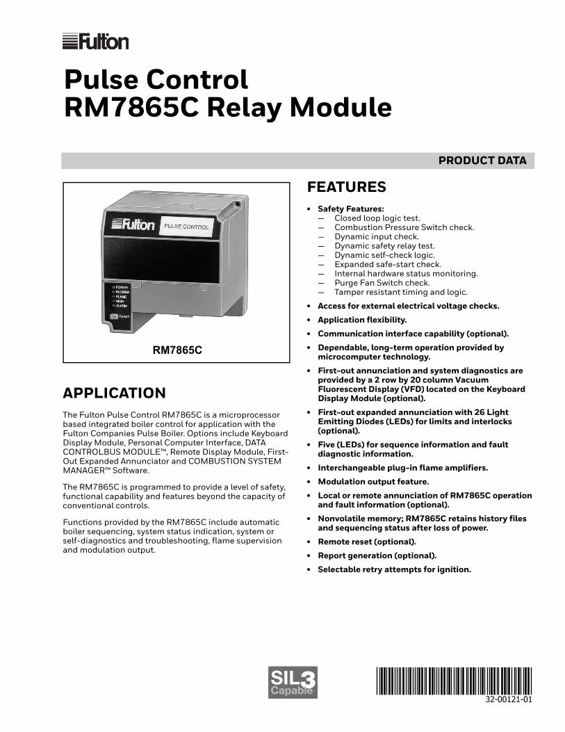
APPLICATIONThe Fulton Pulse Control RM7865C is a microprocessor based integrated boiler control for application with the Fulton Companies Pulse Boiler. Options include Keyboard Display Module, Personal Computer Interface, DATA CONTROLBUS MODULE™, Remote Display Module, First-Out Expanded Annunciator and COMBUSTION SYSTEM MANAGER™ Software.
The RM7865C is programmed to provide a level of safety, functional capability and features beyond the capacity of conventional controls.
Functions provided by the RM7865C include automatic boiler sequencing, system status indication, system or self-diagnostics and troubleshooting, flame supervision and modulation output.
FEATURES• Safety Features:
— Closed loop logic test.— Combustion Pressure Switch check.— Dynamic input check.— Dynamic safety relay test.— Dynamic self-check logic.— Expanded safe-start check.— Internal hardware status monitoring.— Purge Fan Switch check.— Tamper resistant timing and logic.
• Access for external electrical voltage checks.
• Application flexibility.
• Communication interface capability (optional).
• Dependable, long-term operation provided by microcomputer technology.
• First-out annunciation and system diagnostics are provided by a 2 row by 20 column Vacuum Fluorescent Display (VFD) located on the Keyboard Display Module (optional).
• First-out expanded annunciation with 26 Light Emitting Diodes (LEDs) for limits and interlocks (optional).
• Five (LEDs) for sequence information and fault diagnostic information.
• Interchangeable plug-in flame amplifiers.
• Modulation output feature.
• Local or remote annunciation of RM7865C operation and fault information (optional).
• Nonvolatile memory; RM7865C retains history files and sequencing status after loss of power.
• Remote reset (optional).
• Report generation (optional).
• Selectable retry attempts for ignition.
RM7865C
PULSE CONTROL RM7865C RELAY MODULE
32-00121-01 2
• Boiler controller data (optional):— Expanded annunciator status.— Flame signal strength.— Hold status.— Lockout/alarm status.— Sequence status.— Sequence time.— Total cycles of operation.— Total hours of operation.— High cycle rate warning feature.— Fault history providing the six most recent faults:
• Cycles of operation at the time of the fault. • Expanded annunciator data at the time of the
fault. • Fault message and code. • Hours of operation at the time of the fault. • Sequence status at the time of the fault. • Sequence time at the time of the fault.
— Diagnostic information: • Device type. • Flame failure response time. • Manufacturing code. • On/Off status of all digital inputs and outputs. • Prepurge time. • Software revision and version of RM7865 and
optional Keyboard Display Module. • Status of configuration jumpers.
SPECIFICATIONSElectrical Ratings:Voltage and Frequency:
120 Vac (+10%/-15%), 50/60 Hz (±10%).Terminal Ratings: See Table 1.Power Consumption in Run: 10W maximum.Maximum Total Connected Load: 2000 VA.Fusing: Total Connected Load: 15A maximum, Type SC or
equivalent, fast blow.
Environmental Ratings:Ambient Temperatures:
Operating: -40°F to +140°F (-40°C to +60°C).Storage: -40°F to +150°F (-40°C to +66°C).
Humidity: 85% RH continuous, noncondensing.Vibration: 0.5G environment.
Dimensions: Refer to Fig. 1.
Weight: RM7865 with Dust Cover: 1 pound 13 ounces, unpacked.
Approvals:Underwriters Laboratories Inc. listed, File No. MP268,
guide No. MCCZ.Factory Mutual approved, Report No. J.I.1V9A0.AF.IRI acceptable.Federal Communications Commission, Part 15,
Class B—Emissions.
SIL 3 Capable:SIL 3 Capable in a properly designed Safety Instrumented
System. See form number 65-0312 for Certificate Agreement.
Mounting: Q7800A1013 Subbase (Required).
Accessories:Optional Components:
ZM7850A1001Combustion System Manager™.Q7700A1014 Network Interface Base Unit.QS7800A1001 Communication Interface ControlBus™
Module.ZM7850A1001Combustion System Manager™.Q7700A1014 Communication Interface Base
Unit.QS7800A1001 Communication Interface ControlBus™ Module.
203541ControlBus™ 5-Wire Electrical Connector.S7810A1009 Data ControlBus Module™.221729B Dust Cover.S7830A1005 Expanded Annunciator.S7800A1019 Keyboard Display Module.203765 Remote Display Mounting Bracket.203968A Remote Display Power Supply.S7820A1007 Remote Reset Module.221818A Six Feet Extension Cable Assembly.A7800A1002 Tester with 204351 Overlay.S7810M1003 Modbus™ Module.

PULSE CONTROL RM7865C RELAY MODULE
3 32-00121-01
Table 1. Terminal Ratings.
a The relay module must have an earth ground providing a connection between the subbase and the control panel or the equipment. The earth ground wire must be capable of conducting the current to blow the 15A fuse (or breaker) in event of an internal short circuit. The relay module requires a low impedance ground connection to the equipment frame which, in turn, needs a low impedance connection to earth ground. Be careful to verify that mechanically tightened joints along the ground path, such as pipe or conduit threads or surfaces held together with fasteners, are free of nonconductive coatings and are protected against mating surface corrosion.
Table 2. Flame Detection Systems—Flame Amplifier Enabled; JR2 Jumper Clipped (Fig. 2 and 3).
a Order flame rod separately; see holder Instructions.
Terminal No. Description RatingsG Grounda —
L2(N) Line Voltage Common —
3 Alarm 120 Vac, 1A pilot duty.
4 Burner Motor 9.8A, 12 Vac Motor Load
5 Input Line Voltage 120 Vac (+10/-15%), 50/60 Hz.
6 Burner Controller 120 Vac (+10/-15%), 1 mA.
7 Block Intake Switch Input 120 Vac (+10/-15%), 1 mA.
8 Main Main: 2A, 120 Vac Pilot Duty or 65 VA Pilot Duty plus Motorized Valves totalling 1150 VA Locked Rotor, 460 VA Opening, 250 VA Holding.
9 Unused —
10 Ignition 120 Vac, 4.5A ignition.c
F(11) Flame Sensor 60-220 Vac, current limited.
12 Firing Rate High Fire 120 Vac, 75 VA pilot duty.
13 Firing Rate Common 120 Vac, 75 VA pilot duty.
14 Firing Rate Low Fire 120 Vac, 75 VA pilot duty
15 Firing Rate Modulate 120 Vac, 75 VA pilot duty
16 Unused —
17 Unused —
18 Purge Fan Switch 120 Vac (+10/-15%), 1 mA.
19 High Fire Switch Input 120 Vac (+10/-15%), 1 mA.
20 Combustion Pressure Switch 120 Vac (+10/-15%), 2 mA.
21 High Cycle Rate Alarm 120 Vac, 1A Pilot Duty
22 Unused —
Type
Plug-In Flame Signal Amplifiers Flame Failure
Response Time
Applicable Flame Detectors
ColorSelf-
Checking Model Fuel Type ModelsRectification Green No R7847A1041 3 sec. Gas Rectifying
Flame Rod Holdersa
C7004, C7007, C7011, Complete Assemblies: C7008, C7009, Q179.

PULSE CONTROL RM7865C RELAY MODULE
32-00121-01 4
Fig. 1. Mounting dimensions of RM7865 Relay Module and Q7800A Subbase in inches (mm).
Table 3. Sequence Time for Normal Operation.
a Standby and Run can be an infinite time period.b Combustion Pressure Establishing Period (CPEP) or Combustion Pressure and Main Flame Establishing Period
(CPEP/MFEP).c Combustion Pressure Stabilization Period (CPSP) or Combustion Pressure and Main Flame Stabilization Period
(CPSP/MFSP).
PRINCIPAL TECHNICAL FEATURESThe RM7865 provides all customary flame safeguard functions while providing significant advancements in the areas of safety, annunciation and system diagnostics.
Safety Shutdown (Lockout Occurs) if:
1. Initiate Perioda. AC line power errors occurred, see Operation.b. Configuration jumpers have been changed.c. Four minute INITIATE period has been exceeded.
2. Standby Perioda. Combustion Pressure Switch is energized for
120 seconds.b. Configuration jumpers have been changed (after
200 hours of operation).c. Fuel valve terminal is energized.d. Ignition terminal is energized.e. Internal system fault occurred.f. Purge Fan Switch is present for 120 seconds.g. Flame signal is present after 120 seconds (Flame
Amplifier enabled, JR2 jumper clipped).3. Purge Period
a. Block Intake Interlock does not close within 10 seconds.
b. Block Intake Interlock opens after three seconds.c. Combustion Pressure Switch is detected after
ten seconds.
d. Configuration jumpers have been changed.e. Fuel valve terminal is energized.f. Ignition terminal is energized.g. Internal system fault occurred.h. Purge Fan Switch is not energized after 120
seconds.i. Flame signal is detected after ten seconds (Flame
Amplifier enabled, JR2 jumper clipped).j. Failure to close HF switch (240 seconds) if JR1
jumper clipped.4. Main Ignition Period
a. Combustion Pressure Establishing Period (CPEP)/Main Flame Establishing Period (MFEP).(1) Trial for Ignition.
(a) Block Intake Interlock opens.(b) Combustion Pressure Switch is energized.(c) Configuration jumpers have been changed.(d) Fuel valve terminal is energized.(e) Ignition terminal is not energized.(f) Internal system fault occurred.(g)Flame signal is detected (Flame Amplifier
enabled, JR2 jumper clipped).(h)HF switch opens (if JR1 jumper clipped).
(2) Trial for Main.(a) Block Intake Interlock opens.(b) Configuration jumpers have been changed.(c) Fuel valve terminal is not energized.(d) Ignition terminal is not energized.(e) Internal system fault occurred.(f)HF switch opens (if JR1 jumper clipped).
b. Combustion Pressure Stabilization Period (CPSP)/Main Flame Stabilization Period (MFSP).
POWERBLOWERFLAMEMAINALARM
RESET
5(127)
5 (127)
M2602
5-1/4 (133)
REMOVE ONLY FOR TERMINAL TEST ACCESS.1
1
PULSE CONTROLR
Initiate Standby Purge
Ignition Trial
Run Postpurge
b
cIgnitionMain Fuel
Valve5 sec. a 35 sec. 2 sec. 4 sec. 8 sec. a 35 sec.

PULSE CONTROL RM7865C RELAY MODULE
5 32-00121-01
(1) block Intake Interlock opens.(2) Combustion Pressure Switch opens and
number of retries exceeds limit.(3) Configuration jumpers have been changed.(4) Fuel valve terminal is not energized.(5) Ignition terminal is not energized.(6) Internal system fault occurred.(7) No Flame Signal and number of retries
exceeds set limit (Flame Amplifier enabled, JR2 jumper clipped).
5. Run Perioda. Block Intake Interlock Switch opens.b. Configuration jumpers have been changed.c. Fuel valve terminal is not energized.d. Ignition terminal is energized.e. Internal system fault occurred.
6. Postpurgea. Combustion Pressure Switch is energized at end
of postpurge period.b. Configuration jumpers have been changed.c. Fuel valve terminal is energized.d. Ignition terminal is energized.e. Internal system fault occurred.f. Purge Fan Switch is not energized after
120 seconds.g. Flame signal detected at end of postpurge period
(Flame Amplifier enabled, JR2 jumper clipped).
SAFETY PROVISIONS
Internal Hardware Status MonitoringThe RM7865 checks the integrity of the configuration jumpers and internal hardware. The POWER LED blinks every four seconds, signifying an internal hardware check.
Closed Loop Logic TestThe test verifies the integrity of safety critical loads, terminals 8 and 10. If the loads are not energized properly; i.e., the fuel valve terminal is powered during PREPURGE, the RM7865 will lockout on safety shutdown. The RM7865 must react to input changes but avoid the occurrence of nuisance shutdown events. Signal conditioning is applied to line voltage inputs to verify proper operation in the presence of normal electrical line noise such as transient high voltage spikes or short periods of line dropout. Signal conditioning is tolerant of synchronous noise (line noise events that occur at the same time during each line cycle).
Dynamic Input CheckAll system input circuits are examined to verify that the RM7865 is capable of recognizing the true status of external controls, limits and interlocks. If any input fails this test, a safety shutdown occurs and the fault will be annunciated.
Dynamic Safety Relay TestChecks the ability of the dynamic safety relay contact to open and close. Verifies that the safety critical loads, terminals 8 and 10, can be de-energized, as required, by the Dynamic Self-Check logic.
Dynamic Self-Check Safety CircuitThe microcomputer tests itself and related hardware, and at the same time, the safety relay system tests the microcomputer operation. If a microcomputer or safety relay failure occurs and does not allow proper execution of the self-check routine, safety shutdown occurs and all safety critical loads will be de-energized.
Expanded Safe-Start CheckThe conventional safe-start check, which prevents boiler start-up if the Combustion Pressure Switch or Flame Signal is indicated at start-up (Flame Amplifier enabled, JR2 jumper clipped, is expanded to include a Combustion Pressure Switch check, Flame Signal check (Flame Amplifier enabled, JR2 jumper clipped), a Purge Fan Switch Interlock check and safety critical load check during STANDBY.
Off Cycle (Standby or Prepurge) Combustion Pressure Signal Check The Combustion Pressure Switch is monitored during STANDBY. If the Combustion Pressure Switch is closed, a system hold for 120 seconds occurs and start-up is prevented. If the Combustion Pressure Switch is closed after the first three seconds of STANDBY, a safety shutdown occurs and is annunciated.
Off Cycle (Standby or Purge) Flame Signal Strength (Flame Amplifier Enabled, JR2 Jumper Clipped)The Flame Signal is monitored during STANDBY. If a flame signal is detected a system hold condition is activated and startup is prevented. If the flame signal is detected for 120 seconds, a safety shutdown occurs and is annunciated.
Tamper-Resistant Timing and LogicSafety and logic timings are inaccessible and cannot be altered or defeated.
Verified Spark TerminationThe ignition terminal is monitored to verify early spark termination (two seconds ignition and fuel valve only during RUN).
First-Out Annunciation and Self-diagnosticsSequence Status Lights (LEDs) provide positive visual indication of the program sequence: POWER, BLOWER, FLAME, MAIN and ALARM. The green POWER LED blinks every four seconds, signifying that the RM7865 hardware is running correctly.
First-out Annunciation reports the cause of a safety shut-down or identifies the cause of a failure to start or continue the boiler control sequence. It is accomplished by blinking the POWER LED in a progressive sequence and energizing the ALARM LED. First-out Annunciation

PULSE CONTROL RM7865C RELAY MODULE
32-00121-01 6
can also be communicated via the optional Keyboard Display Module with an English text and numbered code. The system distinguishes 31 modes of failure and detects and annunciates difficult-to-find, intermittent failures.
Optional multi-function Keyboard Display Module shows elapsed time during PREPURGE, MAIN IGN and POSTPURGE. As an additional troubleshooting aid, it provides sequence timing, diagnostic information and historical information when a safety shutdown or hold or normal operation occurs.
Self-Diagnostics add to the First-out Annunciation by allowing the RM7865C to distinguish between field (external device) and internal (system related) problems. Faults associated within the RM7865C are isolated and reported by blinking the POWER LED in a progressive sequence and energizing the ALARM LED, see Table 8, or by using the optional Keyboard Display Module. See the Troubleshooting section or 7800 SERIES System Annunciation Diagnostics and Troubleshooting, form 65-0233.
Interlock RequirementsThe following interlock inputs are provided:
Block Intake SwitchThe Block Intake Switch ILK is used to sense if the air intake line to the pluse combustor is blocked (may also be a blocked Exhaust Switch). The Block Intake Switch ILK input (Terminal 7) must close three seconds into Purge; otherwise, a lockout occurs. It must stay closed throughout Combustion Pressure Establishing Period (CPEP), Combustion Pressure Stabilization Period (CPSP), and Run; otherwise, a lockout occurs.
Purge Fan SwitchThe Purge Fan Switch is used to provide combustion air flow.
During PURGE FAN SW. CHECK, the RM7865C ensures that the switch has not been bypassed. If the Purge Fan Switch is closed during STANDBY, theRM7865C will enter a HOLD for a maximum of 120 seconds. If the Purge Fan Switch is still closed at the end of 120 seconds, the RM7865C will enter lockout.
During PREPURGE, the Purge Fan Switch must close. If the Purge Fan Switch is open at any time during PREPURGE, the RM7865C will reset the purge timing and enter a HOLD for a maximum of 120 seconds. If the Purge Fan Switch is still open at the end of 120 seconds, the RM7865C will enter lockout.
During IGNITION, the Purge Fan Switch must remain closed. If the Purge Fan Switch is open at any time during IGNITION, the RM7865C will return to PREPURGE.
During POSTPURGE, the Purge Fan Switch must close. If the Purge Fan Switch is open at any time during POSTPURGE, the RM7865C will reset the POSTPURGE timing and enter a HOLD for a maximum of 120 seconds. If the Purge Fan Switch is still open at the end of 120 seconds, the RM7865C will enter lockout.
High Fire SwitchThe High Fire Switch is used to prove that the air damper has reached the high fire position.
During HIGH FIRE SW. CHECK, the RM7865C ensures that the switch has not been bypassed. If the High Fire Switch is closed during STANDBY, the RM7865C will enter a HOLD for a maximum of 120 seconds. If the High Fire Switch is still closed at the end of 120 seconds, the RM7865C will enter lockout.
During PREPURGE, the High Fire Switch must close. If the High Fire Switch is open at any time during PREPURGE, the RM7865C will reset the purge timing and will enter a HOLD for a maximum of 120 seconds. If the High Fire Switch is still open at the end of 120 seconds, the RM7865C will enter lockout.
During IGNITION, the High Fire Switch must remain closed. If the High Fire Switch opens at any time during IGNITION, the RM7865C will lockout.
Combustion Pressure SwitchThe Combustion Pressure Switch function is only used with the Flame Amplifier is disabled and the JR2 Jumper is intact. The Combustion Pressure Switch is used to sense combustion pressure in the Pulse Combustor.
During COMBUSTION PRESSURE SW. CHECK, the RM7865C ensures that the switch has not been bypassed. If the Combustion Pressure Switch is on during STANDBY and the Burner Controller switch is made, the RM7865C will enter a HOLD for a maximum of 120 seconds. If the Combustion Pressure Switch is still closed at the end of 120 seconds, the RM7865C will enter lockout.
For operation of the Combustion Pressure Switch during IGNITION and RUN, see the Ignition Trials and Run section.
INSTALLATION
WARNINGFire or Explosion Hazard.Can cause severe injury, death or property damage.To prevent possible hazardous boiler operation, verification of safety requirements must be performed each time a control is installed on a boiler.
When Installing this Product…1. Read these instructions carefully. Failure to follow
them could damage the product or cause a hazardous condition.
2. Check the ratings given in the instructions and marked on the product to make sure the product is suitable for your application.
3. Installer must be a trained, experienced, flame safeguard service technician.
4. After installation is complete, check out the product operation as provided in these instructions.

PULSE CONTROL RM7865C RELAY MODULE
7 32-00121-01
WARNINGElectrical Shock Hazard.Can cause severe injury, death or property damage.1. Disconnect the power supply before beginning
installation to prevent electrical shock and equipment damage. More than one power supply disconnect may be involved.
2. Wiring connections for the RM7865C are unique; therefore, refer to Fig. 5 or the correct Specifications for proper subbase wiring.
3. Wiring must comply with all applicable codes, ordinances and regulations.
4. Wiring, where required, must comply with NEC Class 1 (Line Voltage) wiring.
5. Loads connected to the RM7865C must not exceed those listed on the RM7865C label or the Specifications, see Table 1.
6. Limits and interlocks must be rated to carry and break current simultaneously to the ignition transformer and fuel valve.
7. All external timers must be listed or component recognized by authorities who have jurisdiction for the specific purpose for which they are used.
IMPORTANT:1. For on-off gas-fired systems, some authorities
who have jurisdiction prohibit the wiring of any limit or operating contacts in series between the flame safeguard control and the fuel valve(s).
2. This equipment generates, uses and can radiate radio frequency energy and, if not installed and used in accordance with the instructions, may cause interference to radio communications. It has been tested and found to comply with the limits for a Class B computing device of part 15 of FCC rules, which are designed to provide reasonable protection against such interference when operated in a commercial environment. Operation of this equipment in a residential area may cause interference; in which case, the user at their own expense may be required to take whatever measures are required to correct this interference.
3. This digital apparatus does not exceed the Class B limits for radio noise of digital apparatus set out in the Radio Interference Regulations of the Cana-dian Department of Communications.
Mounting Wiring SubbaseNOTE: For installation dimensions, see Fig. 1.
1. Mount the subbase in any position except horizontally with the bifurcated contacts pointing down. The standard vertical position is recommended. Any other position decreases the maximum ambient temperature rating.
2. Select a location in the electrical panel. The Q7800A must be mounted directly in the control cabinet. Be sure to allow adequate clearance for servicing, installation, access and removal of the RM7865C, Dust Cover, electrical signal voltage probes and electrical field connections.
3. For surface mounting, use the back of the subbase as a template to mark the four screw locations. Drill the pilot holes.
4. Securely mount the subbase using four no. 6 screws.
WIRING1. Refer to Fig. 3 for proper subbase wiring. For proper
wiring of optional Keyboard Display Module mounted remotely, DATA CONTROLBUS MOD-ULE™*, Remote Reset Module or Communication Interface Base Unit, refer to Specifications nos. 65-0090, 65-0091, 65-0095 or 63-2278, respectively.
2. Disconnect the power supply from the main discon-nect before beginning installation to prevent electri-cal shock and equipment damage. More than one disconnect may be involved.
3. All wiring must comply with all appropriate electrical codes, ordinances and regulations. Wiring, where required, must comply with NEC Class 1 (Line Volt-age) wiring.
4. Recommended wire size and type: Use no. 14, 16, or 18 copper conductor (TTW60C or THW75C or THHN90C) 600 volt insulation wire for all Line Volt-age terminals. For high temperature installations, use wire selected for a temperature rating above the maximum operating temperature. All leadwires must be moisture resistant.
5. Recommended grounding practices:a. Use the earth ground to provide a connection
between the subbase and the control panel or the equipment. The earth ground wire must be capable of conducting the current to blow the 15A Type SC fast blow fuse (or equivalent) in event of an internal short circuit. The RM7865C needs a low impedance ground connection to the equipment frame which, in turn, needs a low impedance connection to earth ground. For a ground path to be low impedance at RF frequencies, the connection must be made with minimum length conductors that have a maximum surface area. Wide straps or brackets are preferred rather than leadwires. Be careful to verify that mechanically tightened joints along the ground path, such as pipe or conduit threads or surfaces held together with fasteners, are free of nonconductive coatings and are protected against mating surface corrosion.
b. The earth ground terminal for each RM7865C must be grounded to the metal control panel with wire as short as practical. Each ground wire must be capable of carrying a fault current equal to the rating of the protective fuse (20A). A number 14 copper conductor is adequate but wide straps or brackets are preferred rather than leadwires.
6. Maximum wire lengths:a. For the RM7865C, the maximum length of lead-
wire required to the terminal inputs is 300 feet (Control, Purge Fan Switch, Combustion Pres-sure Switch (and Lockout Interlock).
b. Flame Detector (Flame Amplifier enabled, JR2 jumper clipped): (1) Rectifying Flame Rod—265 ft.(2) Ultraviolet Flame Detector—1,000 ft.

PULSE CONTROL RM7865C RELAY MODULE
32-00121-01 8
7. Keep the Flame Detector F and G leadwires isolated from other line voltage wiring and high voltage igni-tion wiring by a minimum of two inches.
8. Make sure loads do not exceed the terminal ratings. Refer to the label on the RM7865C or to the ratings in the Specifications, see Table 1.
Fig. 2. Internal block diagram of the RM7865 (see Fig. 3 for detailed wiring instructions).
9. Check the power supply circuit. The voltage and frequency tolerance must match those of the RM7865C. A separate power supply circuit may be required for the RM7865C with the required disconnect means and overload protection added.
10. Check all wiring circuits and complete the Static Checkout, see Table 6, before installing the RM7865C on the subbase.
11. Install all electrical connectors.12. Restore power to the panel.
CONFIGURATIONJUMPERS
MICROCOMPUTER
RESETPUSHBUTTON
STATUS LEDs
SAFETY RELAY CIRCUIT
POWER SUPPLY
OPTIONALKEYBOARDDISPLAY MODULE
RELAYDRIVECIRCUIT
CONTROLPOWER
REMOTERESET
DDL
DDLCOMMUNICATIONS
INDICATES FEEDBACK SENSINGTO RELAY STATUS FEEDBACKAND LINE VOLT INPUTS
FIELD WIRINGINTERNAL WIRING
IGNITION
MAIN VALVE
1K
RELAYSTATUSFEEDBACKAND LINEVOLTAGEINPUTS
LIMITS
BURNERCONTROLLERSWITCH
HIGH FIRESWITCH
2K2
120 Vac
PURGE FAN SWITCH
RS485
12
3
L1(HOT) L2
5
6
20
7
2K1
10
8
12
13
15
14
18
6K
5 K
3K2K
1
BURNER MOTOR
HF
COM
MOD
LF
4
ALARM
8K1
8K2
9K2
3
L2
1 M24701
19
COMBUSTION PRESSURE SWITCH
BLOCK INTAKEINTERLOCK
BLOCKEDEXHAUSTSWITCH
21 HIGH CYCLE RATE ALARM
7K
1K 5K
6K
3K
PROVIDE DISCONNECT MEANS AND OVERLOAD PROTECTION AS REQUIRED.
K7
K8
K9

PULSE CONTROL RM7865C RELAY MODULE
9 32-00121-01
Fig. 3. RM7865 wiring.
ASSEMBLY
Mounting RM7865CNOTE: For installation dimensions, see Fig. 1.
Relay Module Mounting1. Mount the RM7865 vertically. When mounted on the
Q7800A, the RM7865C must be in an electrical enclosure.
2. Select the location in the electrical enclosure. Be sure to allow adequate clearance for servicing, installation and removal of the RM7865, Dust Cover, electrical signal volt-age probes and electrical con-nections.
3. Allow an optional three-inch clearance minimum on both sides of the RM7865C for electrical signal volt-age probes.
4. Make sure subbase wiring is not projecting beyond the terminal blocks. Tuck the wiring in against the back of the subbase so it does not interfere with the knife blade terminals or bifurcated contacts.
5. Mount the RM7865C by aligning the four L-shaped corner guides and knife blade terminals with the bifurcated contacts on the wiring subbase and tightening the two screws securely without deforming the plastic.
Mounting Dust Cover1. Align the two interlocking ears of the Dust Cover with
the two mating slots on the RM7865C, see Fig. 4.2. Insert the two interlocking ears into the two mating
slots and, with a hinge action, push on the upper corners of the Dust Cover to secure it to the RM7865C.
3. Be sure the Dust Cover is firmly in place.
Fig. 4. Dust cover mounting.
M24702
G
L2
3
4
5 L1
6
7
8
9
10
F
12
13
14
15 MODULATE
16
17
18
19
20
21
22
120V ALARM
BURNERCONTROLLER LIMITS
BLOCK INTAKEINTERLOCK
BLOCKEDEXHAUST SWITCH
IGNITION
MAIN FUEL VALVE(S)
RECTIFYING FLAME ROD
PURGE FAN SWITCH
HIGH FIRE SWITCH
COMBUSTION PRESSURE SWITCH
MASTER SWITCH
L1 (HOT) L2
POWER SUPPLY. PROVIDE DISCONNECT MEANS AND OVERLOAD PROTECTION AS REQUIRED.
DO NOT CONNECT ANY WIRES TO UNUSED TERMINALS.
2
1
LOW FIRE
COMMON
HIGH FIRE
3
2
1
3
4
FLAME AMPLIFIER ENABLED, JR2 JUMPER CLIPPED.
4 USED ONLY IF JR1 JUMPER CLIPPED.
120V, 50/60 HZ
BURNER MOTOR
HIGH CYCLE RATE ALARM
RM7865-2.tif

PULSE CONTROL RM7865C RELAY MODULE
32-00121-01 10
Installing Plug-In Flame Signal Amplifier (Flame Amplifier Enabled, JR2 Jumper Clipped)
1. Disconnect the power supply before beginning installation to prevent electrical shock and equipment damage.
2. Align the amplifier circuit board edge connector with the keyed receptacle. Make sure the amplifier name-plate faces away from the Relay Module, see Fig. 5.
3. Push in the amplifier until the circuit board is fully inserted into the receptacle and then push the amplifier toward the retaining clasp.
4. Verify the amplifier is firmly in place.5. Perform all required checkout tests.
Fig. 5. Installing Plug-In Flame Signal Amplifier.
Installing the Flame DetectorTable 2 and Fig. 6 list the flame detection system available for use with the RM7865C. Make sure the correct combination of amplifier and flame detector(s) is used.
Proper flame detector installation is the basis of a safe and reliable flame safeguard installation. Refer to the instructions packed with the flame detector and the equipment manufacturer instructions.
Keep the flame signal leadwires as short as possible from the flame detector to the wiring subbase. Capacitance increases with leadwire length, reducing the signal strength. The maximum permissible leadwire length depends on the type of flame detector, leadwire and conduit. The ultimate limiting factor in the flame detector leadwire is the flame signal.
Keep the flame detector F and G leadwires isolated from other line voltage wiring and high voltage ignition wiring by a minimum of two inches.
Fig. 6. Flame detector wiring.
OPERATION
Sequence of OperationThe RM7865C has the following operating sequences. See Figs. 7, 8 and Table 4.
INITIATEThe RM7865C enters the five second INITIATE sequence when the Relay Module is powered. The RM7865C can also enter the INITIATE sequence if the Relay Module verifies voltage fluctuations of +10/-15% or frequency fluctuations of +/- 10% during any part of the operating sequence. The INITIATE sequence lasts for five seconds unless the voltage or frequency tolerances are not met. When the tolerances are not met, a hold condition will be initiated and will be displayed on the optional VFD for at least five seconds. When the tolerances are met, the INITIATE sequence will restart. If the condition is not corrected and the hold condition exists for four minutes, the RM7865C will lockout. Causes for hold conditions in the INITIATE sequence are:
• AC line dropout is detected.• AC line frequency error caused by using a 60 Hz device
on a 50 Hz line or vice versa—applies to a device with a date code earlier than 9804.
• AC line noise that can prevent a sufficient reading of the line voltage inputs.
• Brownouts caused by a low line voltage.The INITIATE sequence will be initiated if the burner controller input is de-energized during PREPURGE.
STANDBYTheRM7865C is ready to start an operating sequence when the burner controller input determines a call for heat is present. The boiler switch, limits, operating control, interlocks, critical loads and all microcomputer monitored circuits must be in the correct state for the RM7865C to continue into the PREPURGE sequence.
NORMAL START-UP
PREPURGEThe RM7865C provides a PREPURGE timing of 35 seconds with power applied and the RM7865C operating control indicating a call for heat.
R7847-7.jpg
M22517
G
FX
X
FLAME ROD

PULSE CONTROL RM7865C RELAY MODULE
11 32-00121-01
a. Combustion Pressure Switch, Purge Fan Switch, High Fire Switch, Block Intake Interlock, burner controller, limits, and all microcomputer monitored circuits must be in the correct operating state.
b. The fan motor output, terminal 5, is powered to start the PREPURGE sequence.
c. the Purge Fan Switch and High Fire Switch must close within 120 seconds to start the 35-second PREPURGE; otherwise lockout occurs. The Lockout Interlock must be on when the displayed time is 10 seconds or more; otherwise lockout occurs.
Fig. 7. RM7865 sequence.
Ignition Trials (Flame Amplifier Disabled, JR2 Jumper Intact)
1. Combustion Pressure Establishing Period (CPEP):a. The ignition transformer, terminal 10, is ener-
gized for two seconds prior to opening of the Main fuel valve.
b. The Main fuel valve, terminal 8, is energized for four seconds. The Combustion Pressure Switch, terminal 20, must be proven by the end of the six seconds of CPEP to allow the sequence to continue to the Combustion Pressure Stabilization Period. If the Combustion Pressure Switch is not proven by the end of CPEP (6
seconds), the RM7865C will either recycle to PREPURGE a maximum of three times (JR3 Jumper intact), or lockout (JR3 Jumper clipped).
2. Combustion Pressure Stabilization Period (CPSP):a. At the end of CPEP, the RM7865C enters an eight
second Combustion Pressure Stabilization Period (CPSP). If the Combustion Pressure Switch opens, the RM7865C will either recycle to PREPURGE a maximum of three times (JR3 Jumper intact) or Lockout (JR3 Jumper clipped).
DETAILED OPERATING SEQUENCE
POWER
FLAME
MAIN
BLOWER
ALARM
LEDDISPLAY
OPERATINGCONTROLS
ANDINTERLOCKS
BURNER
COMBUSTION
FIRING RATEMOTOR
FLAMESIGNAL
PRESSURE
RM7865C
POWER
5 35 15
BURNER MOTOR
IGNITION
LIMITS AND BURNER CONTROLLER CLOSED
COMBUSTIONPRESSURE SWITCH
SAFE START CHECK
HFS
FLAME PROVING
TO
10 14 SEC.
BLOCK INTERLOCK
POWER
FLAME
MAIN
BLOWER
CPEP/MFEP
POWER
FLAME
MAIN
6
BLOWER
CPSP/MFSP
POWER
00POSTPURGE
BLOWER
POWER
14RUN
FLAME
MAIN
BLOWER
POWER
00
BLOWER
TIMEDPURGEINITIATE
MAIN FUEL VALVE
TO
PURGE FAN SWITCH TO
TO
TO
POWER
STANDBY
POWER
PREPURGE00
POWER
2CPEP/MFEP
BLOWER
00
4
20
8
L1 6
6 7
18
F G
L1
M247031
1
3
BLOWER
TO13 15 TO13 14TO
TO
13 14TO13 12
5 19
L1
HIGH FIRE SW. CHECK
PURGE FAN SW. CHECK
HIGH FIRE SW. CHECK
COMBUSTION PRESSURE SW. SAFE START CHECK 1
FLAME AMPLIFIER DISABLED, JR2 JUMPER INTACT. COMBINATION PRESSURESWITCH ALSO CHECKED THE FIRST 2 SECONDS OF CPEP.
APPLIES IF JR2 JUMPER IS REMOVED.
APPLIES IF JR1 JUMPER IS REMOVED.
3
2
3
2

PULSE CONTROL RM7865C RELAY MODULE
32-00121-01 12
Ignition Trials (Flame Amplifier Enabled, JR2 Jumper Clipped)
1. Combustion Pressure and Main Flame Establishing Period (CPEP/MFEP).a. The ignition transformer, terminal 10, is ener-
gized for two seconds prior to opening of the Main fuel valve.
b. The Main fuel valve, terminal 8, is then energized for four seconds. The Combustion Pressure Switch, terminal 20, Flame signal, and Purge Fan, terminal 18 (off/open), must be proven by the end of CPEP/MFEP (6 seconds) or the RM7865C will either recycle to PREPURGE a maximum three times (JR3 Jumper intact) or Lockout (JR3 Jumper clipped).
2. Combustion Pressure and Main Flame Stabilization Period (CPSP/MFSP).a. At the end of CPEP/MFEP, the RM7865C enters
an eight second Combustion Pressure and Main Flame Stabilization Period (CPSP/MFSP). If the Combustion Pressure Switch opens or Main Flame is lost, or if the Purge Fan switch closes, the RM7865C will either recycle to PREPURGE a maximum of three times (JR3 Jumper intact) or Lockout (JR3 Jumper clipped).
RUNDuring the RUN sequence, the Fan motor is de-energized. The RM7865C will remain in RUN until one of the following occurs:
1. The controller input, terminal 6, opens, indicating that the demand is satisfied or that a limit has opened.
2. The lockout interlock, terminal 7, opens.3. The Combustion Pressure Switch, terminal 20,
opens (Flame Amplifier disabled, JR2 Jumper intact).
4. The Combustion Pressure Switch opens and/or Flame signal is lost (Flame Amplifier enabled, JR2 Jumper clipped).
POSTPURGEThe RM7865 provides a 35 second POSTPURGE following the completion of the RUN period; and the fan motor output is powered to drive all products of combustion and any unburned fuel from the combustion chamber. The RM7865 will enter POSTPURGE if the operating control input is de-energized during Ignition Trials or RUN.
1. The main fuel valve and ignition, terminals 8 and 10, are de-energized. When the Purge Fan Switch closes, the POSTPURGE period begins.
2. After the 35 second POSTPURGE period is completed, the RM7865 returns to STANDBY.
Fig. 8. Sequence status LEDs.
See Table 4 for further details of Hold conditions.
Table 4. LED Sequence Status Display Information.
boiler Sequence LED EnergizedINITIATE POWER, BLOWER, FLAME, MAIN and ALARM.
STANDBY POWER, BLOWER, FLAME, MAIN and ALARM
STANDBY HOLD: F/G(Flame Detected)
POWER, BLOWER, FLAME, MAIN and ALARM.
STANDBY HOLD: (Purge Fan Switch)
POWER, BLOWER, FLAME, MAIN and ALARM.
PURGE HOLD: (Purge Fan Switch)
POWER, BLOWER, FLAME, MAIN and ALARM.
PURGE POWER, BLOWER, FLAME, MAIN and ALARM.
MAIN IGNITION POWER, BLOWER, FLAME, MAIN and ALARM.
RUN POWER, BLOWER, FLAME, MAIN and ALARM.
POSTPURGE POWER, BLOWER, FLAME, MAIN and ALARM.
RESET/ALARM TEST POWER, BLOWER, FLAME, MAIN and ALARM.

PULSE CONTROL RM7865C RELAY MODULE
13 32-00121-01
Selectable Site-Configurable JumpersThe RM7865C has three site-configurable jumper options, see Fig. 9 and Table 5. The site-configurable jumpers should be clipped with side cutters and the resistors removed from the Relay Module.
Table 5. Site-Configurable Jumper Options.
IMPORTANTChanging configuration jumpers after 200 hours of operation results in a lockout (code 110).
Fig. 9. Selectable site-configurable jumpers.
STATIC CHECKOUT
WARNINGElectrical Shock Hazard.Can cause severe injury, death or property damage.1. Use extreme care while testing the system. Line
voltage is present on most terminal connections when power is on.
2. Open the master switch before installing or removing a jumper on the subbase.
3. Before continuing to the next test, be sure to remove the test jumper(s) used in the previous tests.
4. Replace all limits and interlocks not operating properly. Do not bypass limits and interlocks.
5. Close all manual fuel shutoff valve(s) before starting these tests.
After checking all wiring, perform this checkout before installing the RM7865C on the subbase. These tests verify that the Q7800 Wiring Subbase is wired correctly, and that the external controllers, limits, interlocks, actuators, valves, transformers, motors and other devices are operating properly.
CAUTIONEquipment Damage Hazard.Improper testing can serious damage equipment.Do not perform a dielectric test with the RM7865C installed. Internal surge protectors will break down and conduct a current. This could cause the RM7865C to fail the dielectric test or possibly destroy the internal lightning and high current transient protection components.
Equipment Recommended1. Voltmeter (1 megohm/volt minimum sensitivity) set
on the 0-300 Vac scale.2. Two jumper wires, no. 14 wire, insulated, 12 inches
(305 mm) long, with insulated alligator clips at both ends.
General Instructions1. Perform all applicable tests listed in Static Checkout,
Table 6, in the order listed.2. MAKE SURE THAT ALL MANUAL FUEL SHUTOFF
VALVE(S) ARE CLOSED.3. Perform only those tests designated for the specific
RM7865C model being tested.4. Raise the set point of the operating controller to
simulate a call for heat.5. For each test, open the master switch and install the
jumper wire(s) between the subbase wiring termi-nals listed in the Test Jumpers column of Table 6.
6. Close the master switch before observing operation.7. Read the voltage between the subbase wiring termi-
nals listed in the Voltmeter column of Table 6.8. If there is no voltage or the operation is abnormal,
check the circuits and external devices as described in the last column.
9. Check all wiring for correct connections, tight termi-nal screws, correct wire, and proper wiring tech-niques. Replace all damaged or incorrectly sized wires.
10. Replace faulty controllers, limits, interlocks, actuators, valves, transformers, motors and other devices as required.
11. Obtain normal operation for each required test before continuing the checkout.
12. After completing each test, be sure to remove the test jumper(s).
Jumper Intact ClippedJR1 Modulate Disabled Enabled
JR2 Flame Amp Disabled Enabled
JR3 Flame Failure Retry (3) Lockout
SELECTABLE CONFIGURATION JUMPERS
M22170A
CONFIGURATIONJUMPERS
MODULATE
FLAMEAMP
FLAMEFAILURE
INTACT
DISABLED ENABLED
ENABLED
LOCKOUT
DISABLED
RETRY (3)
CLIP ANDREMOVE
JR1
JR2
JR3
PULSE CONTROL RM7865C RELAY MODULE
32-00121-01 14
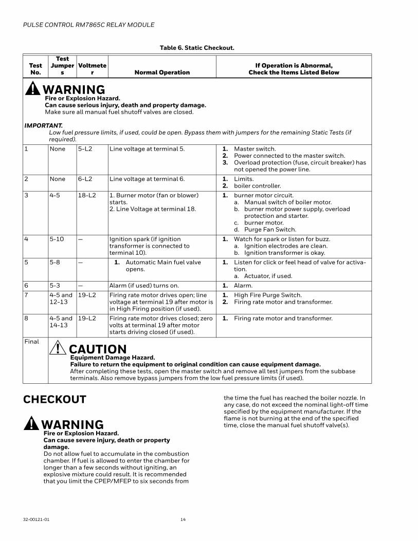
Table 6. Static Checkout.
CHECKOUT
WARNINGFire or Explosion Hazard.Can cause severe injury, death or property damage.Do not allow fuel to accumulate in the combustion chamber. If fuel is allowed to enter the chamber for longer than a few seconds without igniting, an explosive mixture could result. It is recommended that you limit the CPEP/MFEP to six seconds from
the time the fuel has reached the boiler nozzle. In any case, do not exceed the nominal light-off time specified by the equipment manufacturer. If the flame is not burning at the end of the specified time, close the manual fuel shutoff valve(s).
Test No.
Test Jumper
sVoltmete
r Normal OperationIf Operation is Abnormal,
Check the Items Listed Below
WARNINGFire or Explosion Hazard.Can cause serious injury, death and property damage.Make sure all manual fuel shutoff valves are closed.
IMPORTANT.Low fuel pressure limits, if used, could be open. Bypass them with jumpers for the remaining Static Tests (if required).
1 None 5-L2 Line voltage at terminal 5. 1. Master switch.2. Power connected to the master switch.3. Overload protection (fuse, circuit breaker) has
not opened the power line.
2 None 6-L2 Line voltage at terminal 6. 1. Limits.2. boiler controller.
3 4-5 18-L2 1. Burner motor (fan or blower) starts.2. Line Voltage at terminal 18.
1. burner motor circuit.a. Manual switch of boiler motor.b. burner motor power supply, overload
protection and starter.c. burner motor.d. Purge Fan Switch.
4 5-10 — Ignition spark (if ignition transformer is connected to terminal 10).
1. Watch for spark or listen for buzz.a. Ignition electrodes are clean.b. Ignition transformer is okay.
5 5-8 — 1. Automatic Main fuel valve opens.
1. Listen for click or feel head of valve for activa-tion.a. Actuator, if used.
6 5-3 — Alarm (if used) turns on. 1. Alarm.
7 4-5 and 12-13
19-L2 Firing rate motor drives open; line voltage at terminal 19 after motor is in High Firing position (if used).
1. High Fire Purge Switch.2. Firing rate motor and transformer.
8 4-5 and 14-13
19-L2 Firing rate motor drives closed; zero volts at terminal 19 after motor starts driving closed (if used).
1. Firing rate motor and transformer.
Final
CAUTIONEquipment Damage Hazard.Failure to return the equipment to original condition can cause equipment damage.After completing these tests, open the master switch and remove all test jumpers from the subbase terminals. Also remove bypass jumpers from the low fuel pressure limits (if used).

PULSE CONTROL RM7865C RELAY MODULE
15 32-00121-01
WARNINGElectrical Shock Hazard.Can cause severe injury, death or property damage.1. Use extreme care while testing the system. Line voltage is present on most terminal connections
when power is on.2. Open the master switch before removing or
installing the RM7865C.3. Make sure all manual fuel shutoff valve(s) are
closed before starting the initial light-off check.4. Do not put the system in service until you have
satisfactorily completed all applicable tests in this section and any others required by the equipment manufacturer.
IMPORTANT:1. If the system fails to perform properly, refer to
7800 SERIES System Annunciation Diagnostics and Troubleshooting, form 65-0233.
2. Repeat ALL required Checkout tests after all adjustments are made. ALL tests must be satisfied with the Combustion Pressures Switch in its FINAL setting.
Equipment RecommendedVolt-ohmmeter (1 megohm/volt minimum sensitivity).
— 0-300 Vac capability.— 0-6000 ohm capability.— 0-10 Vdc capability.
Checkout Summary— Preliminary inspection—all installations.— Initial light-off check for direct spark ignition.— Combustion Pressure Response Test.— Safety shutdown tests—all installations.
See Fig. 11 for location of component parts and see Fig. 2 or Q7800 Specifications for terminal locations.
Preliminary InspectionPerform the following inspections to avoid common problems. Make certain that:
1. Wiring connections are correct and all terminal screws are tight.
2. Combustion Pressure Switch, Lockout Interlock and Purge Fan Switch are installed and positioned prop-erly. Consult the applicable Instructions.
3. boiler is completely installed and ready to fire; con-sult equipment manufacturer instructions. Fuel lines are purged of air.
4. Combustion chamber and flues are clear of fuel and fuel vapor.
5. Power is connected to the system disconnect switch (master switch).
6. System is in the STANDBY condition. POWER LED is energized.
7. All limits and interlocks are reset.
Flame Signal Measurement (Table 7 and Fig. 10)
Fig. 10. Flame signal measurement.
Measure the flame signal at the appropriate times defined in the following checkout tests. Read the flame signal volts dc at the flame amplifier test jacks + and - (COM).
1. Use a 1 megohm/volt meter with a 0 to 10 Vdc capability.
2. Set the voltmeter to the 0 to 10 Vdc range.3. Insert the positive (red) probe into the + jack of the
flame amplifier. Insert the negative (black) probe into the - (COM) jack of the flame amplifier. See Fig. 10.
4. Allow a few seconds for the meter reading to stabi-lize.
5. The meter reading must be as specified in table 7 after all tests are completed and all adjustments are made.
NOTE: As a option, the flame signal can be checked by using the optional Keyboard Display Module.
if the signal is unstable or less than the minimum acceptable voltage, check the flame detector installation and circuitry:
1. Check the supply voltages at terminal 5(L1) and L2(N). Make sure the master switch is closed, con-nections are correct, and the power supply is of the correct voltage and frequency and is sinusoidal.
2. Check the detector wiring for defects, including: Incorrect connections.
Table 7. Flame Signal.
Flame Detector
Acceptable flame Signal
Amplifier
Minimum Maximum Steady dc
VoltageExpected dc
VoltageFlame Rod R7847A 1.25 Vdc 5.0 Vdc at the
Keyboard Display Module or 5.0 Vdc at a 1 megohm/volt meter.
M17903
NEGATIVE (-)METER LEAD
POSITIVE (+)METER LEAD
1 MEGOHM/VOLT METER

PULSE CONTROL RM7865C RELAY MODULE
32-00121-01 16
a. Wrong type of wire.b. Deteriorated wire.c. Open Circuits.d. Short circuits.e. Leakage paths caused by moisture, soot or
accumulated dirt.3. For a flame rod, make sure:
a. Ground area is large enough.b. Flame rod is properly located in the flame.c. Temperature at the flame rod insulator is no
greater than 500°F (260°C).4. For all optical detectors, clean the detector viewing
window and inside of the sight pipe, as applicable.5. With the boiler running, check the temperature at
the detector. If it exceeds the detector maximum rated temperature:a. Add a heat block to stop conducted heat travel-
ing up the sight pipe.b. Add a shield or screen to reflect radiated heat.c. Add cooling (refer to sight pipe ventilation in the
detector instructions).6. Make sure that the flame adjustment is not too lean.7. Make sure that the detector is properly sighting the
flame.8. If necessary, resight or reposition the detector.
Initial Light-off Check for Direct Spark IgnitionThis check should immediately follow the preliminary inspection. Refer to the appropriate sample block diagram of field wiring for the ignition transformer and fuel valve(s) hookup.
1. Open the master switch.2. Complete the normal checkout of the fuel supply
and equipment as recommended by the equipment manufacturer.
3. Close all manual main fuel shutoff valve(s). Check that the automatic fuel valve(s) are closed. Make sure fuel is not entering the combustion chamber.
NOTE: Low fuel pressure limits, if used, could be open. If so, bypass them with jumpers during this check.
4. Close the master switch and start the system with a call for heat by raising the set point of the operating controller, see Fig. 7, or RM7865C sequencing.
5. Let the sequence advance through PREPURGE. Ignition spark should occur for two seconds after the PREPURGE period. Listen for the click of the main fuel valve(s) after the two seconds.
6. Let the primary sequence complete its cycle.7. Open the manual fuel shutoff valve(s). Remove low
fuel pressure limit jumpers, if used.8. Reset the manual reset push button if the number of
retry attempts is exceeded and recycle the primary sequence through PREPURGE.
9. Watch for the FLAME LED to help determine when the combustion pressure/flame signal is estab-lished. If it is established, proceed to step 15.
10. If the combustion pressure/flame signal is not established within six seconds, or within the normal light-off time specified by the equipment manufacturer, close the manual fuel shutoff valve(s), and open the master switch.
11. Check all boiler adjustments.
12. Wait about three minutes. Close the master switch, open the manual fuel shutoff valve(s), and try again to light-off the boiler. The first attempt may have been required to purge the lines and bring sufficient fuel to the boiler.
13. If necessary, repeat steps 10 through 12 to establish the combustion pressure/flame signal. Then pro-ceed to step 15.
14. When the combustion pressure/flame signal is established, the sequence will advance to Combustion Pressure Stabilization Period/Main Flame Stabilization Period. Make boiler adjustments for combustion pressure stability/flame signal stability and input rating.
15. Shut down the system by opening the boiler switch or by lowering the set point of the operating controller. Make sure the Combustion Pressure Switch opens/flame signal is gone and all automatic fuel valve(s) close.
16. If used, remove the bypass jumpers from the low fuel pressure limit and subbase.
17. Restart the system by closing the boiler switch and/or raising the set point of the operating controller. Observe that the combustion pressure/flame signal is established during MAIN IGN, within the normal light-off time specified by the equipment manufacturer.
18. Make sure all readings are in the required ranges before proceeding.
NOTE: Upon completing these tests, open the master switch and remove all test jumpers from the subbase terminals, limits/controls or switches.
19. Return the system to normal operation.
Safety Shutdown Tests (All Installations)Perform these tests at the end of Checkout after all other tests have been completed. (If used, the external alarm should turn on. Press the RM7865C reset push button to restart the system.)
1. Close the Purge Fan Switch during STANDBY for 120 seconds.
Safety shutdown will occur.
2. Open the Purge Fan Switch during PREPURGE or MAIN IGN period. The RM7865C will return to PRE-PURGE make sure the Purge Fan Switch is open for 120 seconds.
Safety shutdown will occur.
3. Open the Block Intake Interlock during PURGE after the displayed time has reached 10 seconds, or anytime during CPEP, MFEP, SPSP, MFSP, or RUN period.
Safety shutdown will occur.
4. Detect combustion pressure/flame signal for 120 seconds during STANDBY. Detect combustion pressure/flame signal after 10 seconds into measured PREPURGE. Detect combustion pressure/flame signal at end of measured POSTPURGE.
Safety shutdown will occur.

PULSE CONTROL RM7865C RELAY MODULE
17 32-00121-01
5. Failure to detect a combustion pressure switch input/flame signal within the selected retry attempts.a. Close the main fuel manual shutoff valve(s).b. Depress the reset push button.c. Start the system.d. The ignition and main fuel valve should be
energized but the burner cannot light.e. Safety shutdown will occur after the number of
selected retry attempts is exceeded.
WARNINGFire or Explosion Hazard.Can cause severe injury, death or property damage.Applying jumpers across limits, interlocks or the combustion pressure switch can cause an explosion or fire.
IMPORTANT:1. If the RM7865C fails to shut down on any of these
tests, take corrective action (refer to Troubleshooting, RM7865C Diagnostics, and return to the beginning of all Checkout tests.
2. When all Checkout tests have been completed, reset all switches to original states.
TROUBLESHOOTING
Diagnostic InformationFirst-out Annunciation reports the cause of a safety shutdown or identifies the cause of a failure to start or continue the boiler control sequence by blinking the POWER LED and energizing the ALARM LED, see Table 8, or by the optional Keyboard Display Module with an English text and numbered code. The system distinguishes 32 modes of failure and detects and annunciates difficult-to-find, intermittent failures.
Table 8. First-Out Annunciation Codes.
The RM7865C with the optional Keyboard Display Module can monitor input/output terminals and can display the status of the terminal. A terminal description and terminal number are provided. If voltage is detected at the terminal, 1 is displayed; if no voltage is detected at the terminal, 0 is displayed.
Fault HistoryThe RM7865C has nonvolatile memory that allows the Relay Module to retain Historical Information for the six most recent lockouts. Each of the six lockout records retains the cycle when the fault occurred, the hour of operation when the fault occurred and the fault message and boiler status when the fault occurred. The Historical Information can be viewed by the optional Keyboard Display Module; see the Specifications section.
SERVICE NOTE: A lockout condition or restart of an RM7865C can be accomplished by pressing the reset push button on the RM7865C, or by pressing a remote reset push button wired through an optional Keyboard Display Module, Data ControlBus™* Module, or Remote Reset Module. A power-up reset will cause an electrical reset of the RM7865C but will not reset a Lockout condition.
SERVICE NOTE: Remove the access slot covers on the sides of the Q7800A to check voltages.
High Cycle Rate AlarmIf the burner controller has cycled the RM7865C 15 times or more within the most recent hour of power-on time, a high cycle rate condition will be detected and indicated. The indication of the high cycle rate condition depends on whether the control is in a lockout or is not locked out.
NOTE: The High Cycle Rate does not cause a lockout condition.
If the control is locked out and a High Cycle Rate condition existed at the time of lockout:• T21, High Cycle Alarm terminal, will be energized.• The S7800A Keyboard Display Module (if used) will
provide indication of the lockout.• The POWER LED will blink to indicate the fault code.
Pressing the RESET button will clear the lockout condition but will not clear the High Cycle Rate condition.
When the control is not locked out and a High Cycle Rate condition exists:• The High Cycle Rate indication will be retained in the
RM7865C memory and will remain until it is cleared (even if power to the control is interrupted).
• T21, High Cycle Alarm terminal, will be energized.• The POWER LED will repeat a 6-blink pattern.• The S7800A Keyboard Display Module (if used) will
display “Call Fulton Service High Cycle Rate”.
Pressing the RESET button clears the High Cycle Rate condition and measurement of the cycling rate will restart.
WARNINGElectrical Shock hazard.Can cause severe injury, death or property damage.To prevent the possibility of electrical shock, reinstall access slot covers on the Q7800A Subbase after performing voltage checks.
NOTE: In Table 9, Normal sequences are in bold type, while abnormal sequences are not in bold type.
Power/Alarm LED Fault1 Blink Internal Failure.
2 Blinks Combustion Pressure Switch FailureMain Flame Failure
3 Blinks Block Interlock Failure.
4 Blinks Purge Fan Switch Failure.
5 Blinks High Fire Switch
6 Blinks High Cycle Rate

PULSE CONTROL RM7865C RELAY MODULE
32-00121-01 18
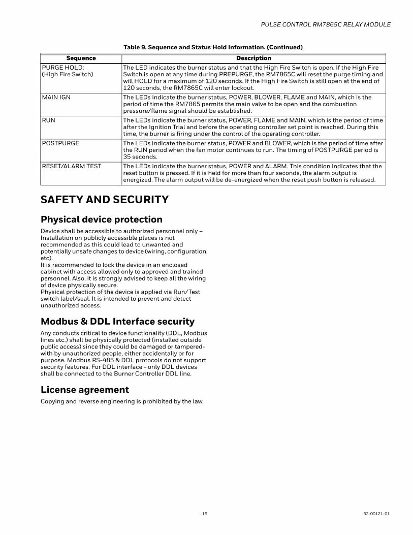
Table 9. Sequence and Status Hold Information.
Sequence DescriptionINITIATE The LED indicates the burner status, POWER, which is a stabilization period for the RM7865
to check for any fluctuation in ac line voltage inputs or control input on power-up during normal operation. The timing of INITIATE period is five seconds before entering STANDBY.
If the RM7865C is in a HOLD status, the following conditions could exist:
INITIATE HOLD: (AC Frequency/Noise)
The LED indicates the burner status, POWER, and that the RM7865C is waiting for excess line noise to clear up. The burner sequence will not advance into STANDBY until the excess line noise, which prevents sufficient reading of the line voltage inputs, ceases or a line frequency error is corrected.
INITIATE HOLD: (AC Line Dropout)
The LED indicates the burner status, POWER, and that AC Line power has momentarily dropped out. The burner sequence will not advance into STANDBY until the AC Line voltage has stabilized throughout the INITIATE sequence.
INITIATE HOLD: (AC Frequency)
The LED indicates the burner status, POWER, and that line frequency is faster than the expected value. The burner sequence will not advance into STANDBY until the line frequency returns to the proper value (device date code of 9804 or earlier).
INITIATE HOLD: (Low Line Voltage)
The LED indicates the burner status, POWER, and that low line voltage has occurred. The burner sequence will not advance into STANDBY until the line voltage is at a sufficient level for proper operating parameters.
STANDBY The LED indicates the burner status, POWER. The burner can be placed in STANDBY by opening the burner switch or if the operating controller indicates its set point has been satisfied. If a demand is present for burner operation, the burner sequence will not advance from STANDBY to PREPURGE until the recycle limits close.
If the RM7865C is in a HOLD status, the following conditions could exist:
STANDBY HOLD: (Flame Detected)
The LED indicate the burner status and that flame is detected prior to a demand from the burner controller. A demand is present for burner operation. The burner sequence will not advance to PREPURGE because flame signal is detected as being present during the safe start check. If the flame signal remains present for 120 seconds, the RM7865C will lockout.
STANDBY HOLD:(Comb. Press.)
The LED indicates the burner status and that the combustion pressure switch is closed (Fulton). A demand is present for burner operation, but the sequence does not advance to PREPURGE. The combustion pressure switch opens. If this time exceeds the 120 second hold, the relay module locks out.
STANDBY HOLD:(CombPres/flame)
The LED indicates the burner status and that the combustion pressure switch is closed and flame detected. (Fulton Pulse only). A demand is present for burner operation, but the burner sequence will advance to PREPURGE until the combustion pressure switch opens and the flame signal clears. If the time exceeds the 120-second hold, the relay module locks out.
STANDBY HOLD: (Purge Fan Switch)
The LEDs indicate the burner status, POWER, and that the Purge Fan Switch Interlock is closed. The burner sequence will not advance to PREPURGE until the Purge Fan Switch Interlock proves open. If this time exceeds the 120 second hold, the RM7865C will lockout.
PURGE The LEDs indicate the burner status, POWER and BLOWER, and that it is the period of time before Ignition Trial when the fan motor is running. The timing of the PREPURGE period is 35 seconds.
PURGE DELAY:(High Fire Jmprd)
The LED indicates the burner status and that the combustion pressure switch is closed and flame is detected (Fulton Pulse only). A demand is present for burner operation, but the burner sequence will not advance to PREPURGE until the combustion pressure switch opens and the flame signal clears. If the flame signal time exceeds the 120-second hold, the relay module locks out.
If the RM7865C is in a HOLD condition the following conditions could exist:
PURGE HOLD: F/G (Flame Detected)
The LED indicate the burner status, POWER, BLOWER and FLAME, and that combustion pressure or Flame Signal is detected. The burner sequence will not advance through PREPURGE because a combustion pressure/flame signal is detected as being present. The sequence will hold waiting for the combustion pressure switch to open/flame signal to go away. If the time exceeds three seconds, the RM7865C will lockout.
PURGE HOLD: T7 (Purge Fan Switch)
The LEDs indicate the burner status, POWER and BLOWER, and that the Purge Fan Switch Interlock is not closed. The sequence will not advance to ignition until the Purge Fan Switch Interlock proves closed. If this time exceeds a 120 second HOLD, the RM7865C will lockout.
PULSE CONTROL RM7865C RELAY MODULE
19 32-00121-01
SAFETY AND SECURITY
Physical device protectionDevice shall be accessible to authorized personnel only – Installation on publicly accessible places is not recommended as this could lead to unwanted and potentially unsafe changes to device (wiring, configuration, etc).It is recommended to lock the device in an enclosed cabinet with access allowed only to approved and trained personnel. Also, it is strongly advised to keep all the wiring of device physically secure.Physical protection of the device is applied via Run/Test switch label/seal. It is intended to prevent and detect unauthorized access.
Modbus & DDL Interface securityAny conducts critical to device functionality (DDL, Modbus lines etc.) shall be physically protected (installed outside public access) since they could be damaged or tampered-with by unauthorized people, either accidentally or for purpose. Modbus RS-485 & DDL protocols do not support security features. For DDL interface - only DDL devices shall be connected to the Burner Controller DDL line.
License agreementCopying and reverse engineering is prohibited by the law.
PURGE HOLD:(High Fire Switch)
The LED indicates the burner status and that the High Fire Switch is open. If the High Fire Switch is open at any time during PREPURGE, the RM7865C will reset the purge timing and will HOLD for a maximum of 120 seconds. If the High Fire Switch is still open at the end of 120 seconds, the RM7865C will enter lockout.
MAIN IGN The LEDs indicate the burner status, POWER, BLOWER, FLAME and MAIN, which is the period of time the RM7865 permits the main valve to be open and the combustion pressure/flame signal should be established.
RUN The LEDs indicate the burner status, POWER, FLAME and MAIN, which is the period of time after the Ignition Trial and before the operating controller set point is reached. During this time, the burner is firing under the control of the operating controller.
POSTPURGE The LEDs indicate the burner status, POWER and BLOWER, which is the period of time after the RUN period when the fan motor continues to run. The timing of POSTPURGE period is 35 seconds.
RESET/ALARM TEST The LEDs indicate the burner status, POWER and ALARM. This condition indicates that the reset button is pressed. If it is held for more than four seconds, the alarm output is energized. The alarm output will be de-energized when the reset push button is released.
Table 9. Sequence and Status Hold Information. (Continued)
Sequence Description

PULSE CONTROL RM7865C RELAY MODULE
® U.S. Registered Trademark© 2018 Honeywell International Inc.32-00121-01 M.S. Rev. 08-18Printed in United States