rnp rnav arrival route coordination - mitre corporation · rnp rnav arrival route coordination paul...
TRANSCRIPT

RNP RNAV ARRIVAL ROUTE COORDINATION Paul V. MacWilliams, Arthur P. Smith, Dr. Thomas A. Becher
The MITRE Corporation, McLean, VA
Abstract Current terminal operations are changing as
more terminal Area Navigation (RNAV) routes are defined that aircraft are expected to fly. Previously, arriving aircraft filing a Standard Terminal Arrival Route (STAR) were given vectors to guide them to the runway when the aircraft transitioned from the STAR and entered the terminal area. There are, however, efforts underway to extend these STARs as routes in the terminal area that overlay the current traffic patterns resulting from the vectors that controllers give to the aircraft. Since these RNAV STAR extensions are overlays, they typically have merge points prior to the merge on final. The challenge for terminal controllers managing merges are wind and speed differentials due to the altitude change along the arrival paths. The geometry of a merge (the number of turns and the length of each route prior to the merge) makes it more challenging to identify a potential merge problem early enough to prevent vectoring an aircraft off the RNAV procedure. To achieve the additional expected benefits and efficiencies from these terminal routes, the controllers will need automation support to assist them in managing the traffic where the routes merge.
Currently there is an automation aid in the U.S. terminal automation systems (Automated Radar Tracking Systems (ARTS) and Standard Terminal Automation Replacement System (STARS)) that helps controllers synchronize two streams of traffic, namely the Converging Runway Display Aid (CRDA). That aid was specifically designed to assist controllers with arrivals to straight-in converging runways once they are on the final approach segment. However, the aid was implemented with enough generality to allow for the application of this automation aid to converging streams anywhere in the terminal area, not being restricted just to runways.
It was pointed out in previous work that when this aid is applied to RNAV routes in the terminal area where the waypoints defining the route are not
co-linear, the projected aircraft indicator positions created by CRDA behave in ways that may not be acceptable to the controllers. Furthermore, the qualification region for each segment is constrained to a trapezoidal shape with the parallel sides must be perpendicular to the route segment. This causes gaps and overlaps between the qualification regions of the two adjoining route segments which results in a loss of a position for the projected aircraft indicator. In that previous work, two enhancements to CRDA were proposed. This paper reports on the implementation of one of those enhancements in a terminal simulation tool in order to perform an engineering analysis and to evaluate operational suitability of this enhancement.
In particular, this paper reports on an examination of the RNP RNAV-based algorithm of the Relative Position Indicator (RPI) of the projected aircraft over a range of expected geometries. First, a simple two segment route projected onto a straight path will be examined. The accuracy and behavior of the projected aircraft indicator depends on route conformance and the geometry of the two route segments, ranging from a fairly benign straight adjoining segments to a challenging 180 degree turn such as a downwind to the base leg of an approach. More complex multi-segmented instances where the waypoints defining the reference route and the RPI route are not co-linear will also be analyzed and compared. The simulation tool replicates the views of terminal controllers and will be used to identify any anomalous projected-aircraft behavior.
In addition, there is always the consideration of wind when using CRDA if the headings along the two routes are significantly different or the aircraft on the routes are simultaneously at different altitudes. This paper will also report the analysis of the effect of winds.
The paper also reports on controller feedback to the RPI tool and elaborates on some potential applications based upon the controller feedback.
Background The Federal Aviation Administration (FAA)
has been implementing RNAV extensions to STAR procedures at busy airports with several periods of high demand. Most of these procedure implementations have been overlays of existing traffic patterns which did not involve extensive airspace redesign. These overlays may have merges prior to the merge on final and minimally have a merge on final at these busy airports. Current RNAV equipage levels at busy airports in the US are between 75-90% and continue to rise. During these periods of high demand, it is desired to keep as many equipped aircraft on the procedures as long as possible to take advantage of the predictable and repeatable manner in which RNAV equipped aircraft can fly a procedure. For merging RNAV terminal arrival routes under periods of high demand, early situational awareness and coordination of flows of traffic on merging routes allow for efficiency gains. MITRE has proposed a controller decision support aid that leverages the RNAV routes and the ability of RNAV equipped aircraft to precisely laterally conform to these routes to provide earlier situational awareness and coordination across merging flows. Aircraft along one flow are accurately projected along complex paths with multiple segments and turns onto another flow with multiple segments and turns. The projection technique was chosen to minimize nonphysical behavior in the projected aircraft indicator that are unacceptable to controllers such as skipping, stalling, and moving backwards. The projection technique does not account for the potential compression that occurs for aircraft decelerating towards a common merge point nor for a significant difference in the wind field between two routes. The projection technique can account for these effects by using trial-and-error. The controller monitoring the behavior of the first few aircraft in the merge could incorporate an offset in the application between the projected and actual aircraft. Additional research is needed to assess
whether there are situations where the projected information is misleading and confusing to the controller causing the controller to perform inefficient rather than more efficient control actions.
Introduction In a previous paper [1], two of the authors
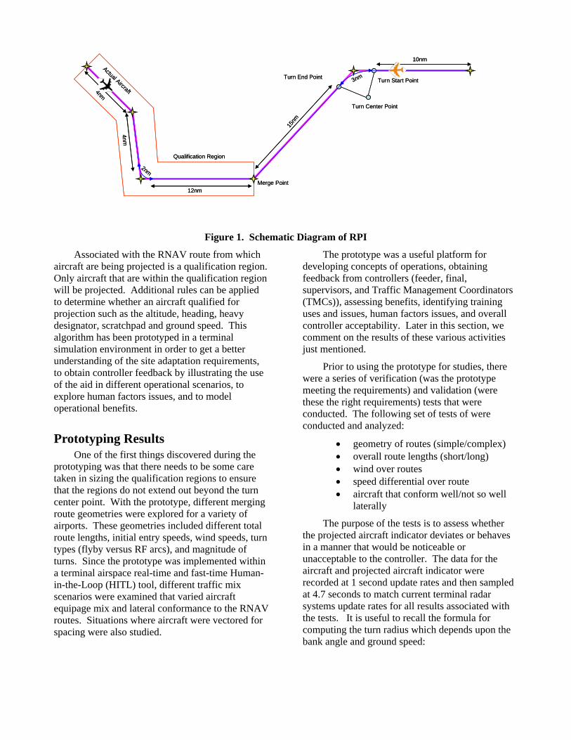
presented the details of the projection algorithm and showed analytically that the nonphysical behavior of projected aircraft indicator was mitigated. The projected aircraft's position is based upon the current position of the real aircraft and its radar position. The projection method is illustrated in Figure 1 where it takes into account turns and the lateral offset of the aircraft relative to the RNAV route. When transitioning from one segment to another, there is a course change and the common waypoint between the segments is generally designed as a flyby waypoint in the terminal area. A flyby waypoint means that the aircraft will start the turn prior to reaching the waypoint (this distance is called the turn anticipation distance) and for RNAV equipped aircraft follow a circular ground arc until tangentially rejoining the new course (the same turn anticipation distance away from the waypoint along the new segment). Not all RNAV aircraft will execute these flyby turns with the same turn radius. The projection algorithm bases the turn radius to use on the average ground speed expected for the turn. The projected aircraft indicator will speed up on the outside of a turn and slow down for aircraft on the inside of a turn. For flight segments that are connected using a radius-to-fix (RF) leg, RNAV equipped aircraft that are capable of executing RF legs and RNP RNAV equipped aircraft (also capable of executing RF legs) will follow exactly the turn radius that is part of the coded procedure. For these arcs, the projected aircraft indicator will not experience any artificial effect on the speed.
Merge Point
Qualification Region
Turn Center Point
Turn End Point
15nm
3nm
10nm
12nm
2nm
4nm
4nm
Actual Aircraft
Turn Start Point
Merge Point
Qualification Region
Turn Center Point
Turn End Point
15nm
3nm
10nm
12nm
2nm
4nm
4nm
Actual Aircraft
Turn Start Point
Figure 1. Schematic Diagram of RPI
Associated with the RNAV route from which aircraft are being projected is a qualification region. Only aircraft that are within the qualification region will be projected. Additional rules can be applied to determine whether an aircraft qualified for projection such as the altitude, heading, heavy designator, scratchpad and ground speed. This algorithm has been prototyped in a terminal simulation environment in order to get a better understanding of the site adaptation requirements, to obtain controller feedback by illustrating the use of the aid in different operational scenarios, to explore human factors issues, and to model operational benefits.
Prototyping Results One of the first things discovered during the
prototyping was that there needs to be some care taken in sizing the qualification regions to ensure that the regions do not extend out beyond the turn center point. With the prototype, different merging route geometries were explored for a variety of airports. These geometries included different total route lengths, initial entry speeds, wind speeds, turn types (flyby versus RF arcs), and magnitude of turns. Since the prototype was implemented within a terminal airspace real-time and fast-time Human-in-the-Loop (HITL) tool, different traffic mix scenarios were examined that varied aircraft equipage mix and lateral conformance to the RNAV routes. Situations where aircraft were vectored for spacing were also studied.
The prototype was a useful platform for developing concepts of operations, obtaining feedback from controllers (feeder, final, supervisors, and Traffic Management Coordinators (TMCs)), assessing benefits, identifying training uses and issues, human factors issues, and overall controller acceptability. Later in this section, we comment on the results of these various activities just mentioned.
Prior to using the prototype for studies, there were a series of verification (was the prototype meeting the requirements) and validation (were these the right requirements) tests that were conducted. The following set of tests of were conducted and analyzed:
• geometry of routes (simple/complex) • overall route lengths (short/long) • wind over routes • speed differential over route • aircraft that conform well/not so well
laterally
The purpose of the tests is to assess whether the projected aircraft indicator deviates or behaves in a manner that would be noticeable or unacceptable to the controller. The data for the aircraft and projected aircraft indicator were recorded at 1 second update rates and then sampled at 4.7 seconds to match current terminal radar systems update rates for all results associated with the tests. It is useful to recall the formula for computing the turn radius which depends upon the bank angle and ground speed:
2
tangv
Rg φ
= (1)
where gv is the ground speed, g is the acceleration of gravity, and φ is the bank angle. The ground speed is obtained by converting the indicated airspeed to the true airspeed based upon altitude density correction and including the wind. RNP RNAV routes can be published with altitude and speed constraints at particular waypoints as well as a designation of whether a waypoint is a flyover (the aircraft flies over the waypoint before turning) or flyby waypoint. For terminal procedures, the general practice is to use only flyby waypoints for arrival routes since this introduces more predictability into how aircraft will execute the turns. If the speed and altitudes are not published as part of the procedure, the local Air Traffic Control (ATC) facility will know the typical values used and these would be entered as part of the adaptation data to size the nominal turn radius.
The following tests were conducted under these conditions:
Test 1: Perfect Track The aircraft is flying at a constant indicated airspeed of 250 kts at an altitude of 12,000 ft. These values are the same as the nominal values assigned to the procedure in the RPI application. The projected aircraft indicator should exhibit a very consistent and regular behavior. The overall lateral deviation of the projected aircraft position indicator should be extremely small and was found not to exceed 0.05 nm.
Test 2: Slow Perfect Track The aircraft is flying at a constant 190 kts and 9,000 ft. These values are lower than the nominal values of the RNP RNAV procedure in the RPI application of 250 kts and altitude of 12,000 ft. A lower altitude and slower speed will result in a smaller turn radius for the actual aircraft. This means that the aircraft will start its turn later and terminate the turn earlier and will result in the aircraft flying slightly outside of the nominal route for a short distance. Starting at the turn anticipation point for the nominal path and continuing to the point where the actual aircraft starting its turn, the projected aircraft indicator speed with decrease since the projected aircraft indicator is traveling a shorter distance along the nominal turn arc than the actual distance flown.
Depending upon the turn of the actual aircraft, the projected aircraft indicator speed will vary depending upon the ratio of the two radii:
indicator actualg g
Rv vR′
= (2)
where R is the nominal turn radius and R′ is the turn radius of the actual aircraft. If R R′ > , then the projected aircraft indicator will have a faster displacement. The larger turn radius will cause the projected aircraft indicator to exhibit a marginally faster displacement and a slight offset to the left. Controller perception of this needs to be tested.
Test 3: Fast Perfect Track The aircraft is flying at a constant 300 kts and 18,000 ft. These values are higher than the nominal values of the RNP RNAV procedure in the RPI application. A higher altitude and faster speed will result in a larger turn radius. This means that the aircraft with start its turn earlier and terminate the turn later. This will result in the aircraft flying slightly inside of the nominal route for a moderate distance. This will cause the projected aircraft indicator to exhibit a marginally slower displacement while the aircraft is in the turn and a slight offset to the right.
Test 4: Offset to inside of turn The aircraft is flying at a constant 250 kts and 12,000 ft. The aircraft is also flying a constant 1.5 nm offset to the right of the nominal path in the RPI application. The aircraft will fly inside the nominal path on the turn causing the projected aircraft indicator to exhibit slowing through the turn segment. The projected aircraft indicator will also show a near constant 1.5 nm offset to the right.
Test 5: Offset to inside of turn, and then rejoining. The aircraft is flying at a constant 250 kts and 12,000 ft. The aircraft is also flying a constant 1.5 nm offset to the right of the nominal path to the first turn. The aircraft then rejoins the nominal path of the RPI application for the second segment of the procedure. The aircraft will fly inside the nominal path on the turn, but will also turn later causing the projected aircraft indicator to exhibit slowing through the turn segment and an offset to the right gradually depreciating from the 1.5 nm offset to 0 as it joins the nominal path.
Test 6: Offset to outside of turn The aircraft is flying at a constant 250 kts and 12,000 ft. The

aircraft is also flying a constant 1.5 nm offset to the left of the nominal path in the RPI application. The aircraft will fly outside the nominal path on the turn causing the projected aircraft indicator to exhibit an increase in speed through the turn segment. The projected aircraft indicator will also show a near constant 1.5 nm offset to the left.
Test 7: Offset to outside of turn, and then rejoining. The aircraft is flying at a constant 250 kts and 12,000 ft. The aircraft is also flying a constant 1.5 nm offset to the left of the nominal path to the first turn. The aircraft then rejoins the nominal path of the RPI application for the downwind. The aircraft will fly outside the nominal path on the turn, but will also turn earlier causing the projected aircraft indicator to exhibit an increase in speed through the turn segment and an offset to the left gradually depreciating from the 1.5 nm offset to 0 as it joins the nominal path.
Test 8: Vectored track The aircraft is flying a constant indicated airspeed of 250 kts at 12,000 ft but does not laterally conform as well to the path due to heading vectors given to the aircraft.
Figure 2 illustrates the range of positive and negative compression that takes place between the
projected aircraft indicator and the actual aircraft for the five tests labeled in the figure. Consider the situation where the projected aircraft indicator from one route initially ties with another aircraft on another route going to a common merge point. Assume that RPI is configured so that there is no built in offset or bias between the projected aircraft indicator and the actual aircraft. Thus, when the projected aircraft indicator position coincides with that of an actual aircraft, it means that the two aircraft will arrive at the common merge point with less than acceptable separation. This also assumes that the two aircraft conform well enough to the RNAV routes to sustain the fidelity of this prediction. Compression refers to the degree of mismatch that can occur due to the non-conformance of either aircraft from their planned RNAV routes. The non-conformance can be due to different speeds, lack of adequate lateral conformance (for example, an aircraft given a direct to a fix), and to some extent lack of altitude conformance which will show up as a speed difference. Figure 2 shows that if there is significant non-conformance than there will be noticeable compression as expected.
Compression Due To Speed Differences Along Image Line
-2
-1.5
-1
-0.5
0
0.5
1
1.5
2
1 61 121 181 241 301 361 421 481
Time (seconds)
Com
pres
sion
(nm
)
Offset Inside of Turn
Fast Perfect Path Perfect Path
Slow Perfect PathOffset Outside of Turn
Figure 2. Potential Mismatches Due to Non-conformance of Aircraft with RNAV Route

Additional tests also examined where a turn ends up getting projected onto another turn. For these tests, both the aircraft route and the RPI route are multi-segmented and contain a turn. The aircraft is flying at a constant 250 kts and 12,000 ft. In both cases the projected aircraft indicator should exhibit very consistent and regular behavior, as turn projections are accounted for in the algorithm.
Test 9: Turn onto turn, no overlap. The along-path positions of the turns do not overlap. When the aircraft is in the turn segment, the projected aircraft indicator is being projected onto a straight segment. When the aircraft indicator is being projected through a turn on the RPI route, the actual aircraft is on a straight segment.
Test 10: Turn onto turn, overlap. The along-path positions of the turns overlap. When the aircraft is in the turn segment, the aircraft indicator is being projected onto a turn on the RPI route.
There were three tests done with a route that had a 180 degree RF leg joining a straight route which was intended to emulate the merge on final. Since the RF leg geometry is built into the RPI application, the projected aircraft indicator should exhibit very consistent and regular behavior that only minimally deviates from that of the actual aircraft. Figure 3 illustrates the geometry of the RF tests.
Test 11: RF track. The aircraft is flying at a constant 210 kts and 5,000 ft. The aircraft conforms to the RNAV path. The aircraft indicator is projected onto a straight route.
Test 12: RF track with 60 kt tailwind on downwind. The aircraft is flying at a constant 210 kts and 5,000 ft. with a 60 kt tailwind on the downwind. This test keeps the same geometry and altitude but adds the 60 kts tailwind on the downwind.
Test 13: RF variable speed and altitude. This test keeps the same geometry, but the aircraft descends out of 12,000 ft for 5,000 ft and reduces speed from 250 kts to 170 kts.
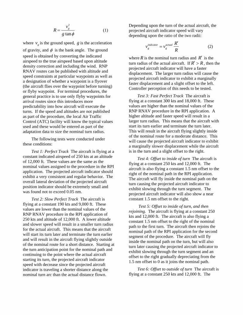
Table 1 summarizes the results of the various tests and illustrates again that if there is significant non-conformance to the RNAV route, then there will be noticeable behavior in the projected aircraft indicator in terms of its speed and compression. The cases where the path of the aircraft is not in conformance, the speed of the projected aircraft inidicator could vary from the speed of the aircraft by more than 100 kts (e.g., scenario 4 and 5). The mitigating circumstances in these cases are 1) the location of this speed deviation is localized to the time that the aircraft is in the turn, and 2) the duration of the deviation is less than a minute since this is the time that it takes for the turn.
Aircraft
RPI
Figure 3. Schematic of the RF Geometry Tested
Table 1. Summary of Test Results
Scenario Max Lat
Dev (nm)
Min Lat Dev (nm)
Max Speed Dev
(kts)
Min Speed
Dev (kts)
1 Perfect Track 0.00 -0.29 1.20 -0.80
2 Slow Perfect Track 0.12 0.00 0.12 -11.78
3 Fast Perfect Track 0.00 -0.31 34.47 -4.31
4 Offset to inside of turn 0.00 -0.14 339.51 -4.49
5 Offset to inside of turn, then rejoining 0.00 -0.20 243.11 -45.25
6 Offset to outside of turn 1.45 -0.16 0.18 -106.84
7 Offset to outside of turn, then rejoining 0.84 -0.16 0.16 -98.80
8 Vectored track 0.05 -0.24 41.29 -95.20
9 Turn onto turn, no overlap 0.00 -0.05 -8.20 -10.20
10 Turn onto turn, overlap 0.00 -0.31 1.20 -0.80
11 RF track 0.12 -0.10 8.16 -4.76
12 RF track with 60 kt tailwind on downwind 0.17 -0.18 22.33 -13.51
13 RF variable speed and altitude 0.06 0.00 4.39 -2.18
Table 1 also illustrates that if aircraft are capable of executing RF legs, then there is good lateral conformance and fairly good speed conformance.
Controller Feedback Feedback on the use of the RPI controller aid
was obtained from controller supervisors and facility managers from Potomac, Atlanta, Chicago, and Houston Terminal Radar Approach Controls (TRACONs). Overall, the feedback was consistently positive with each group identifying applications related to managing merging flows for aircraft on RNAV routes and as a training tool. A couple of the potential applications identified by the controllers are discussed below.
Traffic Management Coordinator (TMC) flowing and sequencing of aircraft was proposed as a potential use of RPI. One of the responsibilities
of the TMC is to make decisions about which aircraft to send to another runway under busy conditions for purposes of runway load balancing. This is illustrated in Figure 4 by the aircraft with the question mark. The TMC is responsible for determining which flow this aircraft, arriving from the northwest, should join. By utilizing RPI, the TMC can toggle between two applications of RPI; one has the aircraft projected onto the northeast flow and the other has the same aircraft projected onto the southwest flow to determine which flow can better accommodate the aircraft. In Figure 5 the TMC identifies the southwest flow as being more suitable for the aircraft and directs the controller to vector and hand-off the aircraft to the south. The darker aircraft are actual aircraft and the light aircraft are the projected aircraft indicators. With the assistance of RPI, the TMC is able to more easily identify the appropriate flow and the resulting merge requires less controller intervention

as shown in Figure 6. In this particular example, RPI is configured so that the projected aircraft indicator ties with the actual aircraft in the merge. All of these illustrations use aircraft symbols rather
than actual controller radar screen display of aircraft with appropriate controller symbols, leader lines, and data blocks.
Figure 4. TMC Options of Which Flow the Aircraft Will Join

Figure 5. Illustration of TMC Decision to Flow Aircraft to Southwest Using RPI
Figure 6. Monitoring of Flowed Aircraft Using RPI

Another application of RPI is sequencing aircraft for runway configuration changes. By toggling between different RPI applications, the last expected aircraft for one runway configuration can be identified as well as the sequencing for the new traffic pattern. Figure 7 illustrates the identification of the ‘last aircraft’ for the west configuration. The two lighter aircraft on the northeast flow are the projected aircraft indicator from the northwest flow. The assumption is that the decision has been made to change the runway configuration and 'last aircraft' has been identified to the feeder controller responsible for that portion of the terminal airspace.
After the 'last aircraft' is identified for the west configuration, the RPI application is toggled to the new traffic pattern and sequencing for the east configuration is determined as depicted in Figure 8. The 'last aircraft' from the northeast lands to the west while additional aircraft arriving from the northeast are now projected onto the northwest flow (the lighter aircraft in Figure 8). The controller could continue to use RPI to identify spacing issues much earlier and mitigate the spacing by using speed control while allowing the RNAV aircraft to laterally conform to the route.
Figure 7. Runway Change Application of RPI: Identification of 'Last Aircraft' in Flow

Figure 8. Runway Change Application of RPI: Indication of Relative Spacing of Flows
Finally, there was consensus that RPI would be useful as a training tool for controllers operating in the new RNP RNAV terminal environment, especially in busy terminal environment with periods of high demand.
One issue with deploying any aid such as this is the training (initial and ongoing) of the users (TMC, supervisors, feeder controllers, etc.). All of the applications identified to date would require the use of RPI on an ongoing basis; essentially during busy pushes at busy airports. For this class of airports, there are typically several arrival pushes throughout the course of a day. If the application were routinely rather than infrequently used, the need for ongoing training is significantly reduced. Additionally, the initial feedback received from the supervisors and facility managers is that the amount of training needed to use RPI will be reasonable.
Summary and Conclusion For busy terminal areas with high demand on
merging RNAV arrival routes, a decision support aid that provides early situational awareness for merging aircraft is a timely problem.
Use of RPI introduces efficiency into the busy terminal operation. These efficiencies show up as regularization of flows that are handed-off from one controller to another. This regularization will help to reduce the average length of the downwind extension.
As shown in this paper, if the aircraft conforms to the defined terminal area RNAV routes, the RPI behaves well. As the traffic deviates from the RNAV routes, the RPI behaves less well but it still may be acceptable to controllers. This last point would still need to be investigated with controllers in a real operational setting.
In order to get this controller aid implemented in the FAA terminal computer systems and used operationally several steps would need to be taken. First, an FAA sponsoring organization would be identified. Next, there would need to be a plan developed to implement this aid. This plan would include the development of a formal software specification and a corresponding test plan. The software would need to be written, tested, and implemented according to the FAA’s automation criteria. A training plan would need to be developed and the controllers would have to be trained in the use of the RPI. The facilities that will

use this aid would then adapt the software to reflect their particular operation. After these steps were completed, the system would start accruing the benefits of the aid.
References [1] Smith, Arthur P. and Thomas A. Becher, A
Study of SPACR Ghost Dynamics Applied to RNAV Routes in the Terminal Area, 24th DASC, Washington, D.C., October, 2005.
Disclaimer The contents of this material reflect the views
of the author and/or the Director of the Center for Advanced Aviation System Development. Neither the Federal Aviation Administration nor the
Department of Transportation makes any warranty or guarantee, or promise, expressed or implied, concerning the content or accuracy of the views expressed herein.
Email Addresses The following are the email addresses for the
authors:
Paul V. MacWilliams [email protected]
Arthur P. Smith [email protected]
Thomas A. Becher [email protected]
25th Digital Avionics Systems Conference
October 15, 2006