road bin editor manual - · pdf fileroad.bin editor manual ... speed if cars branching, they...
TRANSCRIPT

Version: 2012.08.28Language: English
ROAD.BIN EDITOR MANUAL
Tomas Ruzickat [email protected]
www.djbozkosz.wz.czCopyright c© 2005 - 2012
Typeset with LATEX

Road.bin Editor ManualTomas Ruzicka www.djbozkosz.wz.czCopyright c© 2005 - 2012 Verze: 2012.08.28
Contents
1 Preparation for use Road.bin Editor 4
2 Points and links 52.1 Types of points . . . . . . . . . . . . . . . . . . . . . . . . . . . . . . . . . . . . . 52.2 Attributes of points . . . . . . . . . . . . . . . . . . . . . . . . . . . . . . . . . . . 6
3 Interface of editor 83.1 Main window . . . . . . . . . . . . . . . . . . . . . . . . . . . . . . . . . . . . . . 83.2 Insert point panel . . . . . . . . . . . . . . . . . . . . . . . . . . . . . . . . . . . . 93.3 Attributes manager panel . . . . . . . . . . . . . . . . . . . . . . . . . . . . . . . . 93.4 Localization and editor skins . . . . . . . . . . . . . . . . . . . . . . . . . . . . . . 9
4 Using the editor 104.1 Preparation . . . . . . . . . . . . . . . . . . . . . . . . . . . . . . . . . . . . . . . 104.2 Creating points . . . . . . . . . . . . . . . . . . . . . . . . . . . . . . . . . . . . . 104.3 Creating links . . . . . . . . . . . . . . . . . . . . . . . . . . . . . . . . . . . . . . 114.4 Editing and deleting points and their links . . . . . . . . . . . . . . . . . . . . . . . 114.5 Saving . . . . . . . . . . . . . . . . . . . . . . . . . . . . . . . . . . . . . . . . . . 11
A Creating navigation rules 12
B Erasing sectors 14
C The definition and modification of objects in the scene2.bin file dependent on the road.binfile 15C.1 Traffic . . . . . . . . . . . . . . . . . . . . . . . . . . . . . . . . . . . . . . . . . . 15C.2 Semaphores . . . . . . . . . . . . . . . . . . . . . . . . . . . . . . . . . . . . . . . 17C.3 Police roadblocks . . . . . . . . . . . . . . . . . . . . . . . . . . . . . . . . . . . . 17
D Converting numbers 19
2

Road.bin Editor ManualTomas Ruzicka www.djbozkosz.wz.czCopyright c© 2005 - 2012 Verze: 2012.08.28
Introduction
Road.bin - is a file that stores navigation network for the car movement in traffic. The network ismade up by points and their connections.
Navigation are linearly related points.
Road.bin contains only navigation! Car definition is stored in scene2.bin file (see Appendix).
This document summarizes only instructions how to create navigation. Algorithm, for example howAI searches the shortest path, it depends on the self study.
References:http://en.wikipedia.org/wiki/Dijkstra%27s_algorithmnhttp://en.wikipedia.org/wiki/Shortest_path_problemhttp://www.youtube.com/results?search_query=shortest+path
3

Road.bin Editor ManualTomas Ruzicka www.djbozkosz.wz.czCopyright c© 2005 - 2012 Verze: 2012.08.28
Chapter 1
Preparation for use Road.bin Editor
The following conditions are recommended to fulfill for correct functionality:
• Road.bin Editor (ROE for short) - author: me.
• Mafia.GetPos tool (Mafia version 1.0 is required).
• Reduce resolution than is currently used in the operating system and disable fullscreen, both inthe Mafia Setup.exe.
• Extract missions folder with MafiaDataXtractor.
• Copy all 8 models of points from models folder in the editor into Mafia\models folder - tovisualize points in the game.
• Mission without sectors are recommended. Sectors can be deleted using the Sector del tool(please backup the original scene.4ds mission file). See Appendix.
• This script (below) insert into scene2.bin of same mission using BScriptView 4 - 6 (menu Insert→ Other) or DCED 2:
dim flt 1// press objectives (F1) to display navigationlabel CHEwait 1000ctrl read 0, OBJECTIVESif flt[0] = 1, -1, CHEcleardifferencesloaddifferences ”CHED.chg”goto CHE
4

Road.bin Editor ManualTomas Ruzicka www.djbozkosz.wz.czCopyright c© 2005 - 2012 Verze: 2012.08.28
Chapter 2
Points and links
2.1 Types of points
Figure 2.1: Mafia with visualized navigation points.
Following table describes two possible types of points:
Type in hex - sizeof(unsigned short int); Description
Cross pointDefines number of points, these points areused for cross roads
Way pointForms a real road, these points are insertedbetween Cross points
5

Road.bin Editor ManualTomas Ruzicka www.djbozkosz.wz.czCopyright c© 2005 - 2012 Verze: 2012.08.28
2.2 Attributes of pointsFollowing table describes all attributes of Cross and Way points:
Type in hex - sizeof(unsigned short int); Description
Cross pointPosition Coordinates of point - point must be placed
to center of cross roadSpeed If cars branching, they slow down (double of
value is speed in miles per hour and triple ofvalue is in kilometers per hour)
Semaphore Cross road is controlled by semaphore (seeAppendix)
Cross point further contains attributes forfour directions - not all dirs. must be usedWay point direction link Over this point cars ride to next road (if the
link is unused, cars don’t ride to this direc-tion and further attributes will be ignored)
Far active cross point link Link to cross point on the end of road is ac-tive, because in this dir. will be generatedcars (if the link is unused, road will be exist(used by eg AI), but cars not be generated onthis direction)
Far cross point distance To recalculate distance click on Recalculateor in Attributes manager
Angle in radians Angle between cross points (standardly setto 3.14 rad = 180◦)
Priority Sets right of way on cross road- priority: 0 — 100 Roght of way have first car, which come to
cross road- priority: 1 — 100 The direction gives right of wayInformations Standardly set to 0Quaternion type of lanes and their distances These traffic lanes are defined in each di-
rection, distance is calculated from superiorlane to right (for England roads set negativevalues)
- type of lane: 0 Disabled - for outer lane- type of lane: 1 Disabled - for inner lane (eq tram lane, mid-
dle railing, etc.)- type of lane: 2 Traffic- type of lane: 3 Lane for longitudinal parking
6
Road.bin Editor ManualTomas Ruzicka www.djbozkosz.wz.czCopyright c© 2005 - 2012 Verze: 2012.08.28
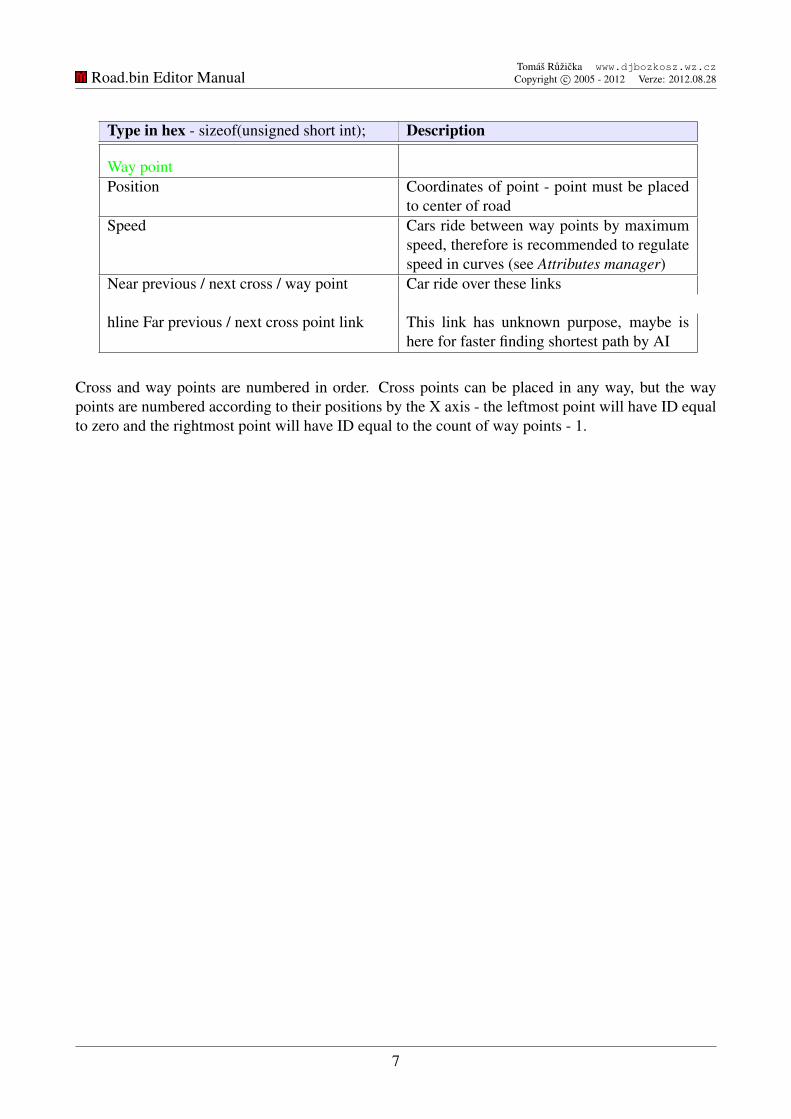
Type in hex - sizeof(unsigned short int); Description
Way pointPosition Coordinates of point - point must be placed
to center of roadSpeed Cars ride between way points by maximum
speed, therefore is recommended to regulatespeed in curves (see Attributes manager)
Near previous / next cross / way point Car ride over these links
hline Far previous / next cross point link This link has unknown purpose, maybe ishere for faster finding shortest path by AI
Cross and way points are numbered in order. Cross points can be placed in any way, but the waypoints are numbered according to their positions by the X axis - the leftmost point will have ID equalto zero and the rightmost point will have ID equal to the count of way points - 1.
7

Road.bin Editor ManualTomas Ruzicka www.djbozkosz.wz.czCopyright c© 2005 - 2012 Verze: 2012.08.28
Chapter 3
Interface of editor
3.1 Main windowThe main window contains a list of all points that are stored in the file. For inserting and managingpoints are used further panels.
Figure 3.1: Mafia is appropriate to run in a window for easy switching between windows.
8

Road.bin Editor ManualTomas Ruzicka www.djbozkosz.wz.czCopyright c© 2005 - 2012 Verze: 2012.08.28
3.2 Insert point panelThis panel is used for inserting new points. In firts and third tab you can insert one cross point or oneway point. Second tab is for easier cross roads creation - you can insert one cross point to center andaround this point is automatically inserted specified number of linked way points.
3.3 Attributes manager panelThis panel simplifies properties managenent of points, because allows set specified values to all crossor way points (or on absolutely all points).
Figure 3.2: Insert point and Attributes manager panels
3.4 Localization and editor skinsActual editor setting is saved in settings.txt file. List of languages is saved in lang\langList.txt file.This file contains names of language files, which editor loads after startup. In lang. file is stored onedefinition on every line - is necessary to abide order and number of lines.
Skin definition is saved in skin\skin.txt. The file contains names of pictures and colors definition,which editor loads after startup.
9

Road.bin Editor ManualTomas Ruzicka www.djbozkosz.wz.czCopyright c© 2005 - 2012 Verze: 2012.08.28
Chapter 4
Using the editor
4.1 Preparation• After loading required mission in Mafia please switch to operating system, run Road.bin Editor
and open (File→ Open...) road.bin file of equivalent mission.
• Then run Mafia.GetPos tool.
• If you move with player in the game you can see in Mafia.GetPos updating coordinates byactual position.
• To generate points click to Export to difference file (Ctrl + E) and save diff\CHED.chg file.Saved are points, which are in range defined in input follow of actually selected point. To showthem in the game hit F1 - objectives.
• You can also use Mafia World Editor to find coordinates.
4.2 Creating points• If you are using Mafia.GetPos then place player in the desired location, where you want to
create point.
• Then open Insert point panel Edit→ Insert point... (Ctrl + I), select tab with required point andin Mafia.GetPos copy to cliboard (Ctrl + C) single line data, which contains three coordianesof player.
• To paste new coordinates click on button next to coordinates. Then fill other parameters (seetable above). Then click on Insert to insert new point.
• Repeat previous three steps to create required number of points in the mission area.
• Meanwhile, you should check location of points in the game by exporting a difference file andhitting F1 key.
10

Road.bin Editor ManualTomas Ruzicka www.djbozkosz.wz.czCopyright c© 2005 - 2012 Verze: 2012.08.28
4.3 Creating links• You can create links in main window of editor.
• In table above are explained all types of links to correctly link points.
• After all modifications you have to recalculate far cross point distances in Attributes manager.
4.4 Editing and deleting points and their links• You can use main window for manage points and links. To delete point click on Edit→ Delete
point (Delete).
• To delete link set the input to value -1.
4.5 Saving• To save file click on File→ Save.
11

Road.bin Editor ManualTomas Ruzicka www.djbozkosz.wz.czCopyright c© 2005 - 2012 Verze: 2012.08.28
Appendix A
Creating navigation rules
Road between cross points (blue) must contain at least two waypoints (green). You cannot link cross point direcly or with onlyone way point. Way points are sorted by position in X asis. Redpoint (here it is cross point) is actually selected point in the edi-tor.
At the end of the road must be cross point too - cars be able toreturn.
Closed loop must contain at least three cross points.
When you are creating a road with three lanes, you have to placethe points to notional centers of road where are the opposite lanespassed. Then, first cross point must have set two lanes and the secondcross point from opposite direction must have set one lane.
12
Road.bin Editor ManualTomas Ruzicka www.djbozkosz.wz.czCopyright c© 2005 - 2012 Verze: 2012.08.28
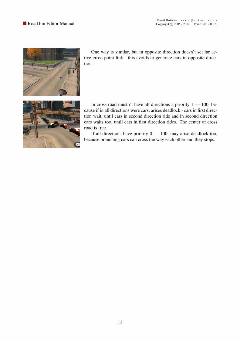
One way is similar, but in opposite direction doesn’t set far ac-tive cross point link - this avoids to generate cars in opposite direc-tion.
In cross road mustn’t have all directions a priority 1 — 100, be-cause if in all directions were cars, arises deadlock - cars in first direc-tion wait, until cars in second direction ride and in second directioncars waits too, until cars in first direction rides. The center of crossroad is free.
If all directions have priority 0 — 100, may arise deadlock too,because branching cars can cross the way each other and they stops.
13

Road.bin Editor ManualTomas Ruzicka www.djbozkosz.wz.czCopyright c© 2005 - 2012 Verze: 2012.08.28
Appendix B
Erasing sectors
Exported points in the CHG file are visible only in the Primary sector. But problem is, if you need tovisualize point in the interior, whose rooms are in own visual sectors. Points cannot be seen in thesesectors.
Sectors and other Zmodeler unsupported objects (glow objects, etc.) can be removed by copyingthe 4DS file into the same folder as the program sector del.exe. In this case it will be scene.4ds filefrom the mission. After run the application is the file automatically removed. To show details, run theapplication via the terminal.
Is strongly recommended to backup the original file, because the application it irreversiblychange.
14

Road.bin Editor ManualTomas Ruzicka www.djbozkosz.wz.czCopyright c© 2005 - 2012 Verze: 2012.08.28
Appendix C
The definition and modification of objects inthe scene2.bin file dependent on the road.binfile
C.1 TrafficTo use navigation map by traffic, you need to insert them into scene2.bin file as object with type:point and object definition with equivalent name and with type: Traffic definition. You can do thiswith DCED 2 or DNC Extractor. Object of point type is standard point. Important is the definition oftraffic. The mission can include only one traffic definition.
DCED 2 allows to create definitions of pedestrians, but DCED 2 very often damages thescene2.bin files and editing pedestrians through this program doesn’t work correctly. Therefore, thereis described more secure way.
In DNC Extractor at first load the mission that contains traffic definition, eg FREERIDE. Thencheck required item in Objects list, eg cars and same item in Objects definitions list. Click to Extractselected program creates DNC files in DNCes folder in the folder where is DNCextractor.exe. Reopenthe application and load required mission. Then click to Import, select DNC files and save the file.
Caution: if the mission was before saved in Mafia World Editor, you need to open mission in thiseditor and delete (shortcut Del) point called Primary Sector (if this point exist). The point has a samename as standard sector, called Primary sector. You can identify this point: if you select a sectorcalled Primary Sector everything will be red, but if you select point called Primary Sector scene willbe same.
Then save the mission. If the point isn’t in the mission, just resave the mission.
15

Road.bin Editor ManualTomas Ruzicka www.djbozkosz.wz.czCopyright c© 2005 - 2012 Verze: 2012.08.28
Extended properties are stored in object definition that you can safely edit with any hex editor.Follow image describes an important values of pedestrians in definition:
Figure C.1: Analysis of traffic object definition in scene2.bin file.
Cars disappear by reaching the outer radius from player: red - float.Generation of cars is determined by position of player and an area which is specified by inner and
outer radius from player: orange, yellow - everything is float.On the navigation map can be generated number of cars specified by: green - unsigned int.Below in file is defined: number of cars in database: cyan - unsigned int and names of cars. String
with name of cars is ended by zero byte and remainder is filled with zero bytes too. For every nameis reserved space 20 bytes. Number of cars is defined before database. After every name is ratio den-sity green - float and flags of special properties red, cyan, blue - everything is flag. Flags can be 0 or 1.
When you are editing this file with hex editor you mustn’t change length of file.But you can change length of object definition in DNC file, but then you have to recalculate length
of item in at start of file.
16

Road.bin Editor ManualTomas Ruzicka www.djbozkosz.wz.czCopyright c© 2005 - 2012 Verze: 2012.08.28
C.2 SemaphoresSemaphore is model, which contains objects with reserved names RED, ORANGE and GREEN, whichare used as signals. Model of semaphore must be inserted in scene2.bin as Model Object, which namemust begin by reserved word in scene: semafor (there are another reserved names too, for example:watercity, taxi, etc.).
Figure C.2: Model of semaphore, here variant with linked glow objects.
Note: when you are creating glow objects, you have to create object with only one polygon(important is origin of this object, because from it will be created glow object), apply to him wantedmaterial (usually Mix with color) and correctly link object to main light in model hierarchy (Tools→ Hierarchy→ Browser...). After export open model in hex editor and 48 bytes before the name ofobject change data 01 00 00 2A to 01 06 00 2A and change 115 bytes after the name of glow object to00 01 00 00 00 00. For check: after this data is double of bytes with ID of used material.
C.3 Police roadblocksPlace designated to create roadblock is defined as DUMMY object in model. Name of object mustbegin ROADBLOCK and must be placed near to road. Whole model must be inserted in scene2.binfile as Model Object, whose name must begin by reversed name in scene: watercity.
Better is create roadblocks on background, eg on imported scene (to import you have to deletesectors and then change byte before lenght of sector object name to 09 - constant for all standartobjects). For model of roadblock you can use in Zmodeler model of cube from primitives. Aftercreating, you have to change type of the object from standard to DUMMY object: Tools→ Filters→Mafia→ Object Settings...
17

Road.bin Editor ManualTomas Ruzicka www.djbozkosz.wz.czCopyright c© 2005 - 2012 Verze: 2012.08.28
Roadblock is generated in the whole width of road and must be active police wanted status witha gun. To create roadblock is randomly choosen police car or nail strip. Maximum count of theseobjects is 15, at the moment. Number of policemans isn’t limited.
Model of tail strip is barrier.4ds and puncture is solved internally. Tail strips disappears whenwanted level is ended.
Figure C.3: Creating of DUMMY objects for roadblocks. As background is here scene.4ds modelfrom FREEKRAJINA mission.
Figure C.4: Example of roadblocks in the game.
18

Road.bin Editor ManualTomas Ruzicka www.djbozkosz.wz.czCopyright c© 2005 - 2012 Verze: 2012.08.28
Appendix D
Converting numbers
Unsigned int is stored in hex form. Float is real number stored according to standard IEEE 754 inform: sign * 2 pow exponent * mantissa.
Numbers are usually stored from least significant byte to most significant byte. It means, whenyou are converting numbers you have to reverse the order of bytes.
For example - integer: decimal form: 22 384 hex form: 00 00 56 12 stored form: 12 56 00 00.For example - real number: decimal form: 15.256 hex form: 41 74 18 93 stored form: 93 18 74
41.Integer numbers you can convert in calculator.Real numbers you can convert with online convertor: http://www.h-schmidt.net/
FloatConverter/IEEE754.html or in program Base Converter and or directly in hex editorHex Workshop.
If you are using Base Converter you have to set the byte order to Intel and data type to float (32).Then you directly copy quaternions of bytes (without reversing the order) from hex editor to converter.
19