road traffic accident handbook - housing.gov.ie · out its role efficiently and safely. the fire...
TRANSCRIPT

ROAD TRAFFIC ACCIDENT HANDBOOK June, 2009
NATIONAL DIRECTORATE FOR FIRE AND EMERGENCY MANAGEMENT JUNE, 2009 RTA HANDBOOK
2
CONTENTS page Introduction to Handbook 4 SECTION 1 The Fire Service and Road Traffic Accidents 5 1.1 RTA Philosophy 1.1.1 Casualty-centred approach 1.1.2 Team approach
1.1.3 Preplanning for RTAs 1.1.4 Challenges of an RTA 1.2 Legislation 1.2.1 Fire Services Act 1981 and 2003 1.2.2 Fire Authorities (Emergency Operations) Regulations, 1987 1.2.3 Other legislation 1.2.4 General advice 1.3 Roles of the Fire Service, HSE and An Garda Síochána SECTION 2 Safety 12 2.1 Scene safety 2.2 Personal safety 2.3 Casualty safety 2.4 Tool safety SECTION 3 RTA Procedure 22 3.1 Overall plan 3.2 Incident Command at road traffic accidents 3.3 Mobilising 3.4 Arrival 3.4.1 Approach to scene 3.4.2 Positioning appliances 3.4.3 Safety from traffic 3.5 Appraisal 3.5.1 Preliminary survey 3.5.2 Inner circle survey 3.5.3 Outer circle survey 3.5.4 Factors to consider 3.6 Plan of action 3.7 Crew roles 3.8 Working zone 3.9 Safety margin 3.10 Motorway and dual carriageway based incidents 3.11 Confirm progress, monitor and evaluate 3.12 Casualty transfer 3.13 Scene preservation 3.14 Make-up 3.15 De-brief 3.16 Standard operating procedures 3.17 Railway procedures
NATIONAL DIRECTORATE FOR FIRE AND EMERGENCY MANAGEMENT JUNE, 2009 RTA HANDBOOK
3
SECTION 4 Vehicle Design and Construction 41
4.1 Car design and construction 4.2 New car technology 4.3 Commercial vehicles 4.4 Buses 4.5 Agricultural and other heavy machinery SECTION 5 RTA Techniques 83 5.1 Vehicle stability 5.2 Glass management 5.3 Rescue and extrication techniques 5.4 Winching techniques SECTION 6 Casualty Care 105
6.1 Initial response 6.2 Kinematics of injury 6.3 Casualty assessment
SECTION 7 RTA Equipment 114 7.1 Hydraulic rescue equipment 7.2 Pneumatic rescue equipment
7.3 Lifting bags/mats 7.4 Reciprocating saws 7.5 Hand tools
SECTION 8 RTA Training 130
8.1 Introduction to RTA training 8.2 Systems approach to training 8.3 RTA exercises
References and further reading 133 Appendix 1 RTA training courses 134 Appendix 2 RTA exercise planning form 136

NATIONAL DIRECTORATE FOR FIRE AND EMERGENCY MANAGEMENT JUNE, 2009 RTA HANDBOOK
4
Introduction to handbook Response to road traffic accidents has been an increasing part of the work of fire services in Ireland over recent years. This Road Traffic Accident Handbook has been prepared to assist fire service personnel in preparing for and responding to the challenges presented by road traffic accidents. The following personnel contributed to the development of the handbook: Mr. E. A. Colville, Senior Assistant Chief Fire Officer, retired, Offaly County Council Mr. Cormac Daly, Senior Executive Fire Officer, Cork County Council Mr. Alan O’Neill, Senior Assistant Chief Fire Officer, Carlow County Council Mr. Eoin O’Donnell, Senior Assistant Chief Fire Officer, Kerry County Council
Mr. Dave Carroll, Chief Fire Officer, North Tipperary County Council Mr. Willie Doyle, Assistant Chief Fire Officer, retired, Waterford City Council Mr. Frank Kenny, Third Officer, retired, Dublin Fire Brigade Mr. Tony Gleeson, Chief Fire Officer, retired, Waterford City Council The Council also acknowledges the assistance received from: Holmatro Rescue Equipment WEBER-HYDRAULIK Rescue Systems Section 4.1 comprises extracts from Fire and Rescue Service Manual Volume 2: Fire Service Operations - Incidents Involving rescue from Road Vehicles, Deprartment for Communities and Local Government. Reproduced under the terms of the Click-Use Licence.

NATIONAL DIRECTORATE FOR FIRE AND EMERGENCY MANAGEMENT JUNE, 2009 RTA HANDBOOK
5
Section 1 The Fire Service and Road Traffic Accidents 1.1 RTA philosophy
As with other areas of fire service operations, Road Traffic Accident (RTA) work has undergone many changes in recent years. This road traffic accident handbook is geared to provide an updated, uniform, systematic approach to incidents, and will endeavour to give guidance to firefighters in areas where little guidance has previously existed. The handbook also includes inputs on rail accident procedures.
Previously, much of our RTA training was based on intuitive evidence, with little
research-based evidence available to brigades. In the early 1990s valuable research was published into road accident injuries, both in the U.S.A. and Europe. This research and more recent studies and experience has served to influence the structure of this handbook, and will assist in ensuring that relevant, job-related RTA training is given.
The team approach to RTA rescues has the stated aim of reducing entrapment times,
and mortality rates, through better organisation and a methodical approach to extrication. In contrast to the traditional view that each rescue is different, the Team Approach recognises that most RTA entrapments have similar characteristics that can be pre-planned for if everything possible is to be done to save lives.
Road Traffic Accidents have placed increased demands on fire service resources
over the last decade. The service has successfully carried out thousands of rescues. Statistics indicate that the number of such incidents will continue to increase.
The improvement in the tools available to the Fire Service has dramatically altered
physical rescue capabilities in spite of technological changes in vehicles. In addition, the presence of First Responders in brigades has increased understanding of RTA-related injuries and improved medical equipment (both in fire brigades and in the Health Service Executive (HSE)) has served to further increase the potential for saving life at RTAs.
1.1.1 Casualty-centred approach – the golden hour Notwithstanding their responsibilities for safety, Incident Commanders should never
lose sight of the fact that the reason for attending an RTA persons trapped is to rescue a casualty/casualties. They must therefore adopt a casualty-centred approach with the principal aim of an efficient rescue whilst doing no further harm.
Successful rescues from entrapments involve a marriage between medical rescue
and physical rescue. It is essential that all extrications are viewed in this context. HSE personnel will advise on the condition of the casualty and on any requirements they may have to gain access, treat or package the casualty and the fire service Incident Commander will decide on the best way to meet these requirements and get the casualty out of the vehicle.
The golden hour philosophy, which was introduced by Dr. R. Adams Cowley in 1961,
recognises that casualties will have a much poorer chance of survival if they are not delivered to definitive care within one hour from the time of the accident. (Definitive care being a hospital operating table.) The golden hour includes the time taken for call-out, travel to the incident, extrication and transport to hospital. This time-scale does not allow for a lengthy extrication time at the accident scene if lives are to be saved and healthy recoveries promoted.
For the majority of road traffic accidents the time taken for extrication should not
exceed 15 minutes. This figure is realistic and can be met if crews are adequately
NATIONAL DIRECTORATE FOR FIRE AND EMERGENCY MANAGEMENT JUNE, 2009 RTA HANDBOOK
6
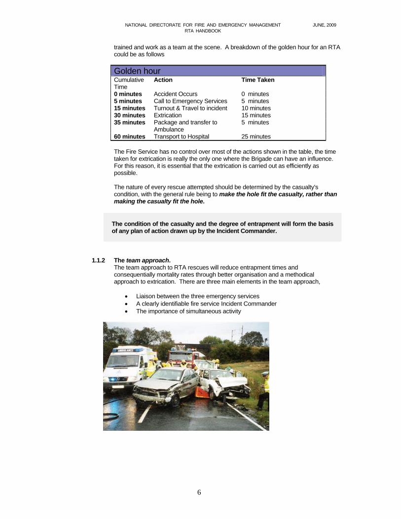
trained and work as a team at the scene. A breakdown of the golden hour for an RTA could be as follows
Golden hour Cumulative Time
Action Time Taken
0 minutes Accident Occurs 0 minutes 5 minutes Call to Emergency Services 5 minutes 15 minutes Turnout & Travel to incident 10 minutes 30 minutes Extrication 15 minutes 35 minutes Package and transfer to
Ambulance 5 minutes
60 minutes Transport to Hospital 25 minutes The Fire Service has no control over most of the actions shown in the table, the time
taken for extrication is really the only one where the Brigade can have an influence. For this reason, it is essential that the extrication is carried out as efficiently as possible.
The nature of every rescue attempted should be determined by the casualty's
condition, with the general rule being to make the hole fit the casualty, rather than making the casualty fit the hole.
The condition of the casualty and the degree of entrapment will form the basis of any plan of action drawn up by the Incident Commander.
1.1.2 The team approach. The team approach to RTA rescues will reduce entrapment times and
consequentially mortality rates through better organisation and a methodical approach to extrication. There are three main elements in the team approach,
Liaison between the three emergency services A clearly identifiable fire service Incident Commander The importance of simultaneous activity

NATIONAL DIRECTORATE FOR FIRE AND EMERGENCY MANAGEMENT JUNE, 2009 RTA HANDBOOK
7
Liaison
One important feature of RTA rescues is the likely attendance of all three emergency services – albeit the fire service is recognised as the principal rescue service. Whilst there are a number of priorities on arrival, early contact must be established with the HSE in order to plan a rescue strategy that satisfies both medical and physical rescue requirements. What is more, this liaison should continue throughout the duration of the rescue. An Garda Síochána now carry out forensic investigation of many serious accidents. It is important that the Fire Service is aware of the issues which may be important in the investigation – condition of tyres, position of gear lever, lights on or off, seatbelt , position of debris, etc. This is discussed in detail in section 3.13.
One Incident Commander There can only be one officer in charge of Fire Services activities at the incident. This
Incident Commander (IC) will be responsible for ensuring that the fire service carries out its role efficiently and safely.
The fire service Incident Commander will liaise with the most senior officers of the
HSE and An Garda Síochána present and will put together a plan of action. Once a plan has been formulated with the medical rescuers (and this can often be fire
service First Responders pending the arrival of ambulance personnel), everyone should be briefed as to the rescue method decided, in order to ensure that all services and individuals pull in the same direction.
Simultaneous activity. Simultaneous activity is where numerous procedures are carried out at the same time. It will lead to a more efficient rescue and a reduction in the time taken to release a trapped casualty. It refers to the fire crew carrying out various activities concurrently and also to the fact that a physical rescue can be done at the same time as a medical rescue.
The hallmark of efficient and effective rescues from road traffic accidents is the achievement of simultaneous medical and physical rescue activities.
After the rescue method has been determined, Incident Commanders should direct initial efforts towards encouraging and facilitating the commencement of medical interventions alongside space creation and disentanglement techniques. Ideally, both rescues (medical and physical) should then continue uninterrupted - with the final length of extrication being determined by whichever type of rescue takes the longer, rather than the sum total of the two.
Neither should the search for simultaneous activity be confined merely to
simultaneous medical and physical rescues. The potential invariably exists to run several different physical rescue activities together at the same time.
A tool staging area can be set up whilst the vehicle is being stabilised. The plastic trim or inner linings can be removed from A, B, or C posts whilst
glass is managed. A door can be removed with a spreader whilst the roof is being removed with
a cutter. Dozens of similar examples of simultaneous activity exist - each one offering rescuers
the opportunity to save precious minutes of the casualty's golden hour. The Incident
NATIONAL DIRECTORATE FOR FIRE AND EMERGENCY MANAGEMENT JUNE, 2009 RTA HANDBOOK
8
Commander should assume a position that permits effective supervision and direction of operations, to ensure that any such opportunity is not missed.
1.1.3 Pre-planning for RTAs This is a relatively new concept, as until recently pre-planning for RTAs centred
around appliance positioning, signs, cones, lighting and other safety considerations – with the general consensus being you can’t pre-plan for an RTA entrapment - every one is different.
At the heart of the team approach philosophy is the recognition that there are a
number of factors common to all RTAs persons trapped that can and should be pre-planned for. This is in addition to the obvious requirements for scene safety.
As already mentioned, there will be a need for a clearly identifiable Incident
Commander, for liaison, and for simultaneous activity.
There will be a casualty requiring urgent medical attention, therefore at least one person should be delegated this task in advance.
There will be a vehicle requiring stabilising in order to minimise unwanted
movement.
A tool staging area will need to be set up as physical rescue activities will be necessary to disentangle the casualty.
Personnel will have to be detailed as tool operatives as someone is trapped
in wreckage.
Each tool operator will have to have someone detailed to work with them to provide hard protection between the casualty and tool in use.
An extrication method will have to be contrived with which to rescue the
casualty. This can and should be pre-planned for, too!
All of the above activities can be pre-planned, crew members should have tasks pre-assigned which they have been trained to do.
1.1.4 Challenges of an RTA Analysis shows that three particular problems are common to all RTAs and will have
to be overcome at some stage. They are:
i. The presence of a casualty requiring urgent hospitalisation. ii. Difficulty in gaining full access to the casualty. iii. Restricted space in which to work.
The key to solving all three problems is ... Create space!!

NATIONAL DIRECTORATE FOR FIRE AND EMERGENCY MANAGEMENT JUNE, 2009 RTA HANDBOOK
9
1.2 Legislation There are various pieces of legislation that are relevant to road traffic accidents.
Some of these are directly concerned with fire service involvement, others, such as the Dangerous Substances Act, and the Transport of Goods Regulations relate to the vehicles involved in the RTA. Only the legislation directly related to fire brigade involvement is considered here. The most relevant legislation is
The Fire Services Acts 1981 and 2003
The Fire Authorities (Emergency Operations) Regulations, 1987.
The Road Traffic Acts
The Safety, Health and Welfare at Work Act 2005
1.2.1 Fire Services Act 1981 and 2003 This is the main legislation governing fire authorities and fire brigade activities. A
number of sections of the Act relate to RTAs.
Section 15, although general in nature, puts a duty on a fire authority to adequately train its personnel. This would apply to RTA activities as well as all other areas.
Section 25 states that a fire authority may carry out or assist in any
operations of an emergency nature, whether or not a risk of fire is involved, and may make such provision for the rescue or safeguarding of persons and protection of property as it considers necessary for the purposes of that function.
Section 27 deals with control of operations at a fire or other emergencies.
This section clearly identifies who is in charge at a fire, but does not state who is in charge at a non-fire emergency.
Section 28 states that the person in charge at a fire or non-fire emergency
may do anything which s/he considers necessary for … protecting or rescuing persons or property.
Section 28 also states that no legal action can be taken against the person in
charge at a … non-fire emergency. Any damage incurred to property is to be deemed to have been caused by the fire or emergency for insurance purposes.
1.2.2 Fire Authorities (Emergency Operations) Regulations 1987
These Regulations were issued so that the person in charge at non-fire emergencies would have the appropriate powers and immunity. The Regulations called for the authority to nominate a person in sole charge of emergency operations for the authority and to identify deputies and goes on to say that in their absence the person who is in charge of the attending fire brigade is in charge of the emergency operations of the fire authority. As the person in charge of the fire authority’s emergency operations has now been legally identified, the intention of the Regulations is that the person in charge has immunity from legal action under section 28 of the Fire Services Act, 1981 and 2003. It should be noted that these Regulations affirm that the fire service Incident Commander (IC) is in charge of fire service emergency operations; they do not give
NATIONAL DIRECTORATE FOR FIRE AND EMERGENCY MANAGEMENT JUNE, 2009 RTA HANDBOOK
10
the IC control over HSE or Garda Síochána functions if these services are present. The various roles of the three main emergency services are discussed below.
1.2.3 Other legislation Drivers of fire brigade vehicles are given some qualified exemption from the
requirements of the Speed Limit Regulations and the Road Traffic Act Byelaws (i.e. the Rules of the Road). These exemptions are given effect in Section 27 of the Road Traffic Act 2004 and are subject to a duty of care to the safety of road users. This is vitally important, and basically it means that a driver of a fire appliance can drive above speed limits or breach certain rules of the road, provided s/he does not endanger the safety of road users. The exemptions only apply in emergencies.
The Safety, Health and Welfare at Work Act 2005 would apply to brigade activities at an RTA as it applies to all brigade activities.
1.2.4 General advice The fire authority is part of the local authority and, as such, particular care should be
taken in the way an accident scene is left after an incident. If the roadway is in a condition which could be deemed to be dangerous, the Garda Síochána should be informed and the Local Authority Roads/Area personnel should be called out to erect signs and warn/control traffic as necessary. Do not leave a situation that may be deemed to be dangerous without adequate signs and/or personnel before roads personnel arrive.
It is generally not a function of the fire service to clean up roadways; however, in
some parts of the country it may be more practical for the brigade, if they are in attendance, to hose down the road, etc. The critical point is that the scene must be maintained in a safe manner, by providing signs, warning tape, cones etc. or remaining at the scene until the personnel responsible for cleaning the road arrive. The decision as to whether it is safe to re-open a road should be a matter for the local authority Roads Section.
Traffic control, crowd control, evacuation, etc., are functions of An Garda Síochána,
and they should be requested to carry out these functions as necessary. If they are not in attendance, they should be called and requested to do whatever is necessary. In the meantime the Incident Commander may deem it necessary for members of the Fire Service to control the traffic for safety reasons. This is discussed further in Section 3.
NATIONAL DIRECTORATE FOR FIRE AND EMERGENCY MANAGEMENT JUNE, 2009 RTA HANDBOOK
11
1.3 Roles of the Fire Service, HSE and An Garda Síochána The Fire Service is part of a team responding to RTAs. The other members of the
team are generally the HSE and the Garda Síochána. For a rescue to be carried out efficiently it is essential that each agency is aware of their role and the roles of the other agencies and that communication or liaison continues throughout the incident.
HSE personnel will advise on the condition of the casualty and on any requirements
they may have to gain access, treat or package the casualty and the fire service Incident Commander will decide on the most appropriate way to meet these requirements and facilitate the safe removal of the casualty from the vehicle.
Similarly, An Garda Síochána will have needs with regard to preservation of the
scene, traffic management or recovery of fatally injured persons and the fire service Incident Commander will endeavour to assist in any way possible.
If one or both of the other agencies are not in attendance, the fire crew may have to
carry out functions that would normally be associated with the HSE or An Garda Síochána, the execution of these functions to be relinquished on the arrival of the relevant agency.
The Framework for Major Emergency Management identifies An Garda Síochána as
being the lead agency for a major emergency involving an RTA. These pre-nominations of lead agencies are to apply to all emergencies, from normal through the full range of major emergencies.
1.3.1 Fire Service role. The functions of a Fire Brigade at a Road Traffic Accident are
1. Physical Rescue of trapped persons 2. Extinguish fires 3. Deal with hazardous material 4. Assist the HSE with casualty care 5. Assist An Garda Síochána with body recovery. 6. Ensure scene is safe for the brigade to carry out its functions.
1.3.2 Garda Síochána role The functions of An Garda Síochána at a Road Traffic Accident are
1. Preservation of life and render assistance to the injured 2. Preserve the scene 3. Traffic management 4. Collect evidence and forensic work 5. Assist the Coroner
1.3.3 HSE role The functions of the HSE at a Road Traffic Accident are
1. Provision of medical aid to casualties 2. Provision of medical advice. 3. Triage of casualties. 4. Casualty transport.
NATIONAL DIRECTORATE FOR FIRE AND EMERGENCY MANAGEMENT JUNE, 2009 RTA HANDBOOK
12
Section 2 Safety
This section considers safety under the headings of
scene safety, personal safety, casualty safety and welfare, and, tool safety.
There are also safety issues inherent in the procedures described in later sections. See section 3.10 for information on scene safety at motorway and dual carriageway based incidents.
2.1 Scene safety
Safety at the scene of a road traffic accident is primarily the responsibility of the Incident Commander but each member of the crew has a duty to be mindful of their own safety and that of others at the scene. The Incident Commander may appoint a Safety Officer if crew numbers are sufficient.
Scene safety begins in the appliance en route to the incident when the Incident Commander identifies the roles each crew member will carry out, including erecting warning signs and providing fire cover.
The Incident Commander will have the safety of the crew, the casualty’s safety and the safety of other personnel at the scene as the highest priority when arriving at the incident.
The safety procedures in the following sections should be considered when brigades respond to road incidents.
2.1.1 Mobilising:
Mobilise as per pre-determined attendance (PDA) Request An Garda Síochána to attend. If there are persons reported, confirm that the HSE have been notified. Request further information (e.g. traffic and access difficulties, number and type of vehicles,
number and type of casualties, hazmats/flammable materials involved). Allocate roles to crew members
2.1.2 Arrival:
Approach the incident slowly and carefully. If two appliances are responding, try to approach from opposite directions. Carry out a preliminary survey, including a dynamic risk assessment, as soon as possible, in
accordance with the National Incident Command System.
2.1.3 Positioning appliances: Park in a fend-off position to block the relevant lane (see section 3.10 for motorways). If two appliances are in attendance, the second appliance should park in a fend-off position
beyond the incident. The smaller or lighter vehicle should be parked on the side of the incident which is less likely to be exposed to traffic.
Park one appliance close enough to allow a hose-reel to provide fire cover for the scene. When parking, consider the need for lighting the scene. If a fend-off appliance is moved to allow access for an ambulance, recovery truck, etc., it
should be returned to the fend-off position immediately. The driver should consider the side of the appliance that the RTA gear is stored on when
parking the vehicle. Road closure may have to be considered for narrow roads or to ensure safety of personnel on heavily trafficked roads (see 2.1.9).
NATIONAL DIRECTORATE FOR FIRE AND EMERGENCY MANAGEMENT JUNE, 2009 RTA HANDBOOK
13
2.1.4 Signs:
If the Garda Síochána have not already done so, warning signs should be erected approximately 200m to 400m each side of the incident. When positioning signs, consider the drivers’ sight lines and take into account any bends, dips or rises, and also the weather conditions – for example, ice, fog, rain. Signs on larger/faster roads should be a greater distance from the incident than they would be on smaller roads.
Always watch approaching traffic when positioning signs. A car travelling at 112km/h (70mph) travels 31metres in a second!
Leave the signs in place until the brigade is about to leave the scene. When collecting signs have someone watch for/ warn approaching traffic.
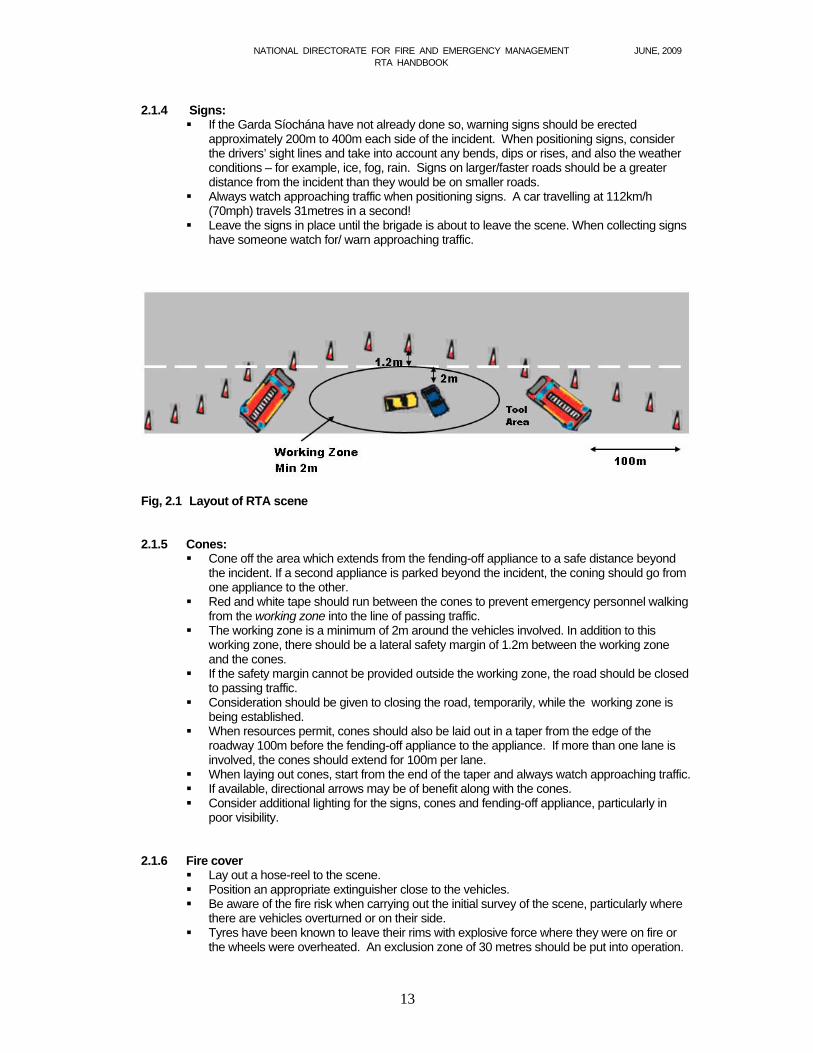
Fig, 2.1 Layout of RTA scene 2.1.5 Cones:
Cone off the area which extends from the fending-off appliance to a safe distance beyond the incident. If a second appliance is parked beyond the incident, the coning should go from one appliance to the other.
Red and white tape should run between the cones to prevent emergency personnel walking from the working zone into the line of passing traffic.
The working zone is a minimum of 2m around the vehicles involved. In addition to this working zone, there should be a lateral safety margin of 1.2m between the working zone and the cones.
If the safety margin cannot be provided outside the working zone, the road should be closed to passing traffic.
Consideration should be given to closing the road, temporarily, while the working zone is being established.
When resources permit, cones should also be laid out in a taper from the edge of the roadway 100m before the fending-off appliance to the appliance. If more than one lane is involved, the cones should extend for 100m per lane.
When laying out cones, start from the end of the taper and always watch approaching traffic. If available, directional arrows may be of benefit along with the cones. Consider additional lighting for the signs, cones and fending-off appliance, particularly in
poor visibility.
2.1.6 Fire cover Lay out a hose-reel to the scene. Position an appropriate extinguisher close to the vehicles. Be aware of the fire risk when carrying out the initial survey of the scene, particularly where
there are vehicles overturned or on their side. Tyres have been known to leave their rims with explosive force where they were on fire or
the wheels were overheated. An exclusion zone of 30 metres should be put into operation.
NATIONAL DIRECTORATE FOR FIRE AND EMERGENCY MANAGEMENT JUNE, 2009 RTA HANDBOOK
14
2.1.7 Lighting Appliances parked in the fend-off position should have their flashing blue lights turned on. A control vehicle may also have its blue lights turned on. Portable blue lights may be used to supplement coning; however, care should be taken not
to add to the confusion at the scene. Excessive and inappropriate use of emergency warning lights at the scene of an incident
can have an adverse effect on the traffic. Only appliances protecting the scene and control vehicles should display blue warning lights to the traffic. All other emergency vehicles should park within the area protected by these appliances.
Consider illuminating the rearmost appliance, either by search light or by telescopic floodlight mast to provide additional safety at night or in fog. Care should be taken to ensure that any such lighting does not adversely interfere with road users.
Lighting of accident warning signs may also be advantageous. The use of vehicle hazard warning lights can be helpful, but it is important to ensure they do
not obscure the visibility of blue flashing lights. Consider use of portable lighting and generators to increase illumination of an accident
scene. Use of lighting towers may be helpful in improving safety of personnel at the scene.
2.1.8 Risk assessment
The safety of the scene should be reviewed regularly throughout the incident, and the dynamic risk assessment should be updated accordingly. Additionally, each fire authority should have a written risk assessment for all road based incidents which its personnel are likely to attend.
2.1.9 Traffic control
The control of traffic is the responsibility of An Garda Síochána, and they should be requested to carry out this function, if necessary. Where members of the fire service have to manage traffic, the following points should be considered: Live traffic should not be allowed to drive through an area where fire-fighters are working.
The traffic should be stopped until signs are put in place, fend-off appliances are correctly positioned, and cones and safety margins are in place.
If, at a RTA, the working zone and a 1.2m safety margin around the vehicles cannot be kept free from traffic, the road should be closed. The minimum width required for single lane traffic is 3m.
Care should be taken to warn traffic that the road is blocked; this may involve having someone beyond the last stationary vehicle to warn oncoming traffic that they will have to stop.
Consideration should be given at an early stage, in consultation with the roads section and An Garda Síochána, to utilising local and/or national radio to highlight issues arising from the incident.
Always face traffic on roadway when putting out or removing signs or cones. Put out signs on the obstructed side first. Narrowing cones in the centre of the roadway can be used to slow traffic. Consider a STOP/GO system. The fire-fighter controlling the unobstructed side of the road is in charge of the traffic control
operation. Always have an escape route for traffic controllers. Traffic control should only be undertaken by appropriately trained personnel. Firefighters doing traffic control should be visible, - wear high visibility jackets and have a
torch or illuminated baton as appropriate. Firefighters controlling traffic should have good communications and should ideally be
visible to each other. When firefighters are controlling traffic, they should:
o be seen, o take control – be certain they know what they want people to do, o get the drivers’ attention, o give clear signals, and, o do not stand in the line of traffic.
NATIONAL DIRECTORATE FOR FIRE AND EMERGENCY MANAGEMENT JUNE, 2009 RTA HANDBOOK
15
2.1.10 Make-up
The scene of a road incident should never be left in an unsafe condition. Control of the site should be handed over to the relevant authority, or appropriate warning signs and cones should be left in place, or it should be cleaned up satisfactorily and made safe.
Collect and stow all gear before moving the fend-off appliances, cones or signs. When finally collecting cones and signs, firefighters wearing the appropriate high visibility
garments should be in place to warn traffic. Always watch approaching traffic when collecting cones and signs.
2.1.11 Hazards
Hazards which can be expected at the scene of a road traffic accident include the following
Traffic; Safety from traffic is discussed in section 3. Personnel should also be alert to emergency vehicles moving at the accident scene
Road conditions; Road conditions may have contributed to the accident or may be dangerous as a result of the accident.
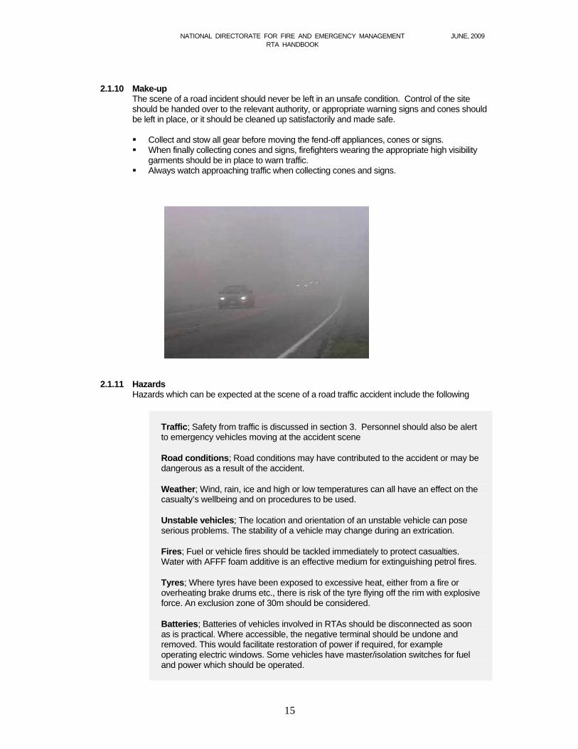
Weather; Wind, rain, ice and high or low temperatures can all have an effect on the casualty’s wellbeing and on procedures to be used.
Unstable vehicles; The location and orientation of an unstable vehicle can pose serious problems. The stability of a vehicle may change during an extrication.
Fires; Fuel or vehicle fires should be tackled immediately to protect casualties. Water with AFFF foam additive is an effective medium for extinguishing petrol fires.
Tyres; Where tyres have been exposed to excessive heat, either from a fire or overheating brake drums etc., there is risk of the tyre flying off the rim with explosive force. An exclusion zone of 30m should be considered.
Batteries; Batteries of vehicles involved in RTAs should be disconnected as soon as is practical. Where accessible, the negative terminal should be undone and removed. This would facilitate restoration of power if required, for example operating electric windows. Some vehicles have master/isolation switches for fuel and power which should be operated.

NATIONAL DIRECTORATE FOR FIRE AND EMERGENCY MANAGEMENT JUNE, 2009 RTA HANDBOOK
16
Fuel leaks; Fuel leaks can be caused by rupture of the fuel tank or by ruptured pipes (particularly with fuel pumps continuing to operate). Ignitions should be switched off and batteries disconnected. In extreme situations, where substantial
amounts of fuel have leaked, it may be necessary to consider laying a blanket of foam, particularly if upholstery has become impregnated with petrol. Otherwise,
spilled fuel should be absorbed with appropriate absorbent material. Where there are no sewers, or where there are no environmental considerations, small quantities of leaked fuel may be washed off the road with a high pressure hose-reel. It is important to remove ignition sources, to prevent smoking, and to keep unnecessary personnel out of a danger area where there has been a fuel leak.
Loads on commercial vehicles; The loads on HGVs or commercial vans may have become unstable as a result of the accident. The stability and content of the loads should be checked as part of the initial appraisal.
Hazardous materials; Where hazardous materials are identified on a vehicle or in the area of the accident, appropriate measures should be taken.
Electricity; If lighting or electricity transmission poles have been involved in a collision, be aware of the danger of live wires.
Sharp metal; Sharp metal may be exposed following the accident or as a result of cutting procedures, either way sharp edges should be covered to prevent injury.
Airbags, pre-tensioners; The Inner Circle survey should identify any danger within the vehicle. These are discussed in detail in Section 4.
Hybrid vehicles; Developments in the area of hybrid vehicles, those which use both electricity and petrol for power, will see an increasing amount of these vehicles on the roads in Ireland over the coming years. These vehicles will require special procedures to be followed when involved in a road traffic accident due to the high voltages involved (up to 300 volts in some cases) and the nature of the electrolyte used in the batteries.
As the rescue progresses, hazards may appear which were not a concern initially, such as sharp metal or a change in the stability of the vehicle. The Incident Commander should periodically carry out a dynamic risk assessment of the situation and should be continuously aware of the safety issues involved.
2.2 Personal safety
The Safety, Health and Welfare at Work Act, 2005 places on all employees duties which must be complied with, regardless of the nature of the work involved. These duties include taking reasonable care for their own safety and health as well as the safety and health of anyone else who may be affected by their acts or omissions. The Act also requires that proper use is made of all tools and of all personal protective equipment provided for use at work. The minimum requirements for PPE at an RTA are:
High visibility (hi-viz) jacket, vest or surcoat (Class 3 to EN 471:2003). Protective clothing (fire tunic and leggings) to protect from sharp edges. Protective gloves to protect from sharp edges. Surgical gloves should be worn as appropriate when dealing with casualties. They
can be worn under fire/protective gloves. Head protection should be worn at all times.
NATIONAL DIRECTORATE FOR FIRE AND EMERGENCY MANAGEMENT JUNE, 2009 RTA HANDBOOK
17
Safety boots with protective toe cap. Eye protection, goggles or safety glasses with helmet visor – goggles or safety
glasses are not adequate on their own when using tools. Respiratory protection as appropriate Ear defenders when using certain tools.
In addition to making proper use of PPE, each member of a crew must be conscious of his/her own safety at all times when working at an RTA. The following points should be borne in mind,
Dismount away from traffic.
Stay within safe working area/coned area.
Do not work under unstable vehicles.
Be aware of hazards such as, glass, spilt fuel, battery acid, hydraulic fluid, sharp metal, blood, needles, LPG, hazardous materials, glass dust,
Check the vehicle for any supplemental restraint systems (SRSs), undeployed airbags, seat belt pre-tensioners
Use proper manual handling techniques.
Change around tool operators when appropriate.
Ensure any emergency personnel have appropriate PPE.
2.3 Casualty safety and welfare During the course of an incident involving an RTA, either the Ambulance personnel or the Emergency First Responders in the fire crew will be dealing with the casualty. It is essential that the work of the fire crew to release the casualty does not have an adverse effect on the casualty.
2.3.1 Stability – casualty safety The reason a vehicle is stabilised is to prevent movement, and thus minimise the likelihood of any further injury to the casualty. During the process of releasing a trapped casualty, vehicle parts will be removed or shifted causing a change in the weight distribution. Additionally, rescue personnel will be getting in and out of the vehicle. For these reasons, it is necessary to check the stability of the vehicle regularly.

NATIONAL DIRECTORATE FOR FIRE AND EMERGENCY MANAGEMENT JUNE, 2009 RTA HANDBOOK
18
2.3.2 Glass management – casualty safety
When glass is being managed, a casualty is vulnerable to glass fragments and to dust that may be generated by cutting glass. It is essential that casualties are protected by hard protection, such as a shield, and by soft protection, such as clear plastic sheeting. Casualties should also be given respiratory protection.
2.3.3 During rescue – casualty safety
Be aware of the effect hazards inherent in the vehicle (such as deployed or undeployed airbags and pre-tensioners) would have on the casualty.
Hard protection must be provided to the casualty whenever tools are being used.
Constantly chock and block when moving or lifting any part of the vehicle.
When using tools above a casualty be very conscious of the possibility of the tool slipping.
If metal is being cut or moved, watch very closely to make sure that parts of the vehicle or the tools do not impinge on the casualty.
Warn the casualty of any procedure which will be noisy and consider providing ear protection if necessary.
Protect the casualty from the weather. Be aware of the effects of wind, rain and temperature on the casualty.
When discussing matters concerning the casualty’s condition, be conscious of the fact that the casualty could be listening.
2.4 Tool safety
It is very important that the manufacturer’s instructions are followed - whatever tool is to be used. The operator’s manual should be read and understood before using any equipment. In addition, the tool should be kept in good working order by following the recommended guidelines for the servicing and maintenance of the equipment. The tools should be checked regularly – for example, on drill nights. As there is considerable physical effort required when using rescue tools, and many tools are heavy, correct manual handling techniques should be used at all times. Appropriate PPE should be worn at all times. When using tools, the operators should be alert to the danger posed by SRS systems, airbags, pre-tensioners etc. Trim or other linings should be removed to enable any potential hazards to be seen.
NATIONAL DIRECTORATE FOR FIRE AND EMERGENCY MANAGEMENT JUNE, 2009 RTA HANDBOOK
19
2.4.1 General hydraulic tool safety.
The following points should be borne in mind when using hydraulic tools; Never position yourself between a tool and the vehicle. Before starting the pump-
o Untwist hoses o Connect hoses o Make sure couplings are secure o Have pump in neutral/dump valve open
Never use damaged or out-of-date hoses Do not stand on hoses Do not use hoses to carry, pull or move tools Keep power unit out of the way If resources permit, leave crew member at pump Avoid hot refuelling Stop pump when not required Carry tools using designated handles only Never put hands on jaws, arms or blades of tools Remove all plastic or other interior trim in vehicles before cutting or spreading to
check for airbag inflators, SRS systems or any other potential hazards. After use tools should be left in safe position
o Cutters: tips slightly overlapping o Rams: plunger slightly extended o Spreaders/combi: tips slightly open
Return tools to the tool staging area when not in use Maintain a clear working zone around the vehicle which should be a minimum of
2m width. Control parts of vehicle that may be ejected when cutting or spreading Cover all sharp protrusions Beware of vehicle distortion Constantly monitor vehicle stability Wear full PPE
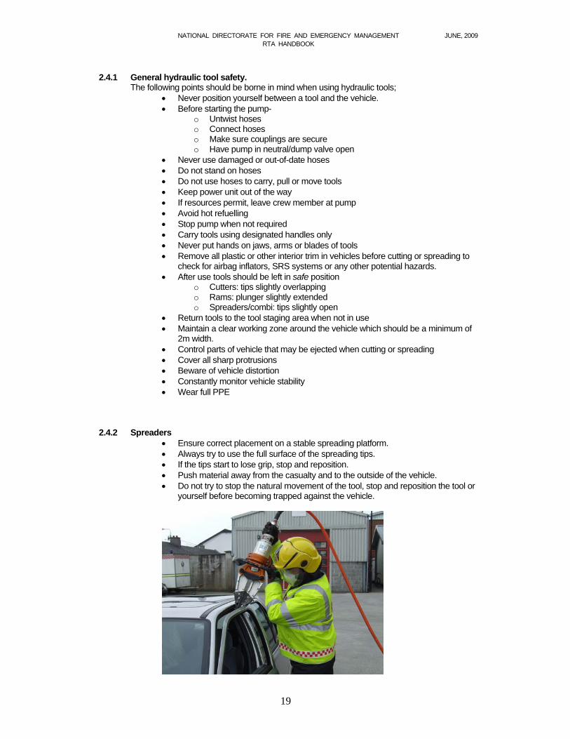
2.4.2 Spreaders
Ensure correct placement on a stable spreading platform. Always try to use the full surface of the spreading tips. If the tips start to lose grip, stop and reposition. Push material away from the casualty and to the outside of the vehicle. Do not try to stop the natural movement of the tool, stop and reposition the tool or
yourself before becoming trapped against the vehicle.
NATIONAL DIRECTORATE FOR FIRE AND EMERGENCY MANAGEMENT JUNE, 2009 RTA HANDBOOK
20
2.4.3 Cutters
Remove all plastic or other interior trim in vehicles before cutting to check for airbag inflators, SRS systems or any other potential hazards.
Position the cutter so that it is at a 90 degree angle to the cutting surface. Ensure the material to be cut is as far into the blade recess as possible. Avoid
cutting at the tips. If the cutter is twisting and the blades begin to separate, stop cutting and reposition. Avoid cutting unsecured objects. Beware of cutting hardened steel or gas struts. Do not try to stop the natural movement of the tool, stop and reposition the tool or
yourself before becoming trapped against the vehicle. 2.4.4 Rams
Beware of sudden kicking out due to loss of grip. Use sill supports where appropriate. Position the ram so the control handle is accessible and that it will not get in the
way of the extrication. Position the ram such that, if the control handle moves, it will not trap the user’s
hands. If ramming is interrupted, be careful of the handle orientation; do not accidentally
begin to lower or release pressure on the ram. Pay attention to both purchase points. Provide stabilisation below the lower purchase point before applying pressure. Chock and block as you go.
2.4.5 Compressed air tools
Ensure that the equipment is in good working order and that the supply of air is adequate. Wear the appropriate PPE, which may include ear defenders in the case of compressed air tools. Ear protection may also be required for the casualty.
Zip Gun
Connect tool and check hose connections before turning air supply on. Do not free run. Ensure spring is properly located. Never point gun at anyone. Disconnect from air supply and exhaust air when changing chisels. After use, isolate supply, exhaust air and disconnect tool and hoses.
Cengar saw
Connect tool and check hose connections before turning air supply on. Disconnect from air supply when changing blades. After use – isolate supply, exhaust air and disconnect tool and hoses.
2.4.6 Vehicle winch
To be used by an appropriately trained person. Ensure anchorages are of sufficient strength. Check anchor points constantly. Always indicate rope runs. Never step over loaded wire ropes. Wear reinforced gloves when using wire rope. Keep the wire straight, avoid kinks, loops and sharp bends. Ensure the load is within the rated capacity of the machine. Always use force absorption blankets, or similar. Never tow a vehicle with the winch.

NATIONAL DIRECTORATE FOR FIRE AND EMERGENCY MANAGEMENT JUNE, 2009 RTA HANDBOOK
21
2.4.7 Lifting bags
Make sure load will be stable when lifted. Ensure lift is as vertical as possible. Avoid slippery surfaces Avoid sharp or jagged metal. Avoid hot engines, exhausts and catalytic converters. Pack as you lift, do not crawl under supported loads. Do not exceed maximum lifting capacities.
2.4.8 Electrical equipment Ensure that all electrical equipment is in good working order and that the generator is adequate for the purpose. Wear the appropriate PPE, which may include ear, eye and respiratory protection for both the user and the casualty. Ensure that running cables do not present a trip hazard.
NATIONAL DIRECTORATE FOR FIRE AND EMERGENCY MANAGEMENT JUNE, 2009 RTA HANDBOOK
22
Section 3 RTA Procedure
3.1 Overall plan The overall plan should be similar for all road traffic accidents and should contain the following elements,
1. Scene safety
2. Early casualty contact
3. Stabilise the vehicle
4. Rapid entry and casualty care
5. Create space
6. Rescue, package and transport
3.2 Incident Command at road traffic accidents The principles of the National Incident Command System should be adhered to at a road traffic accident, as at any incident. The Incident Commander (IC) at a road traffic accident should consider the following points
Plan: Keeping in mind the principle of the golden hour, a plan of action should be
drawn up in accordance with the overall plan, which ensures simultaneous activity and the safety of all concerned.
Roles: The IC should have a clear understanding of the roles and responsibilities of all the agencies responding to the RTA.
Liaison; There should be good communications between all services at the scene. The IC should keep his own crew fully briefed throughout the operation.
Positioning: Effective command and control comes with good positioning - far enough away to have an overview of the whole incident scene around the vehicle, whilst close enough to step in and have a close up look should the need arise.
Anticipation: The IC should constantly be thinking ahead and should anticipate equipment and manpower needs. An alternative plan should be drawn up - in case it is needed.
Risk Assessment: The issue of safety should be constantly reviewed and the risk assessment should be updated.
3.3 Mobilising A minimum of two vehicles should be mobilised initially, to provide appropriate fend-off
arrangements to all road-based incidents. The Incident Commander should carry out a dynamic risk assessment on attendance, and decide on additional vehicle requirements, if appropriate.
For non-persons-reported incidents, the second vehicle should be made available at scene if required as soon as possible. The Incident Commander can make appropriate arrangements
NATIONAL DIRECTORATE FOR FIRE AND EMERGENCY MANAGEMENT JUNE, 2009 RTA HANDBOOK
23
should the second vehicle be required to be mobilised to a different incident. Any changes to scene safety arrangements should be agreed between the Incident Commanders of the attending emergency services prior to changes taking place.
The absolute minimum recommended pre-determined attendance (PDA) for all motorway and dual carriageway based incidents is two water tenders or a water tender and an emergency tender of equivalent size to a water tender.
While it may be desirable to provide full-size, water tenders to carry out fend-off procedures, the type of vehicle and number of drivers in a station will determine how many/what type of vehicles can be mobilised.
Where it is not possible to have at least two full size water tenders to provide fend off, the vehicles to be used should have the following characteristics:
Ability to take an impact of a moving vehicle - for example, minimum 3.5 tonnes gross vehicle weight.
Visible at all times with appropriate high visibility markings Identification/warning lights at a height for better advance warning Ability to provide appropriate protection of the working area
An Garda Síochána should be requested to attend any road incident which a brigade are
responding to as traffic control is a function of the Garda Síochána. If there are persons reported, the Incident Commander should request RCC to confirm that
the HSE have been requested. The Incident Commander should request that the local authority Roads Section should be
informed of any road-based incident which may involve the condition of the roadway or any safety issues concerning the roadway.
The Incident Commander should seek Information on traffic and access difficulties, the
number and types of vehicles involved, number and situation of casualties and if hazardous or flammable materials are involved. Such information will assist the Incident Commander in deciding if the PDA needs to be varied, and in preparing for the situation to be faced.
3.4 Arrival When arriving at the scene of a road traffic accident, the Incident Commander should have safety uppermost in mind and should be conscious of the approach to the scene, the positioning of appliances and the problems posed by traffic.

NATIONAL DIRECTORATE FOR FIRE AND EMERGENCY MANAGEMENT JUNE, 2009 RTA HANDBOOK
24
3.4.1 Approach to scene Extreme care is required in approaching an RTA site, as conditions, such as poor weather, oil
spill or traffic back-up, may all pose dangers. The approach by appliances arriving at the incident should be slow and controlled for the following reasons:-
a. Weather conditions and visibility. b. Road conditions.
c. Obstacles and debris. d. Casualties (i) wandering around in a dazed state, or, (ii) thrown onto roadway. e. Build-up of traffic due to the accident. f. Opportunity to drop off crew member with accident signs. g. Following traffic will be slowed down.
An advantage of a slow approach is that the Incident Commander will have an opportunity to make a brief assessment of the incident. If two appliances are responding to an incident they should try to approach from opposite directions, if possible.
3.4.2 Positioning appliances Responding appliances should be positioned to protect the casualties and emergency personnel at the scene. The appliance should be parked behind the crashed vehicles, at an angle to the road centre, to deflect traffic, i.e. in fend-off position. Adequate space should be left between a fending-off appliance and the incident for other appliances, and for an equipment/ tool staging area. A second appliance or other fire service vehicle, if available, should be parked in a fend-off position beyond the incident. If a smaller or lighter vehicle is used, it should be parked on the side of the incident which is less likely to be exposed to traffic.
Fig. 3.1 Layout of RTA scene
Ambulances should generally park ahead of the scene of the crash. Fire appliances should be positioned close enough to enable hose reels/ jets to be laid out to cover the scene, but should not be so close that exhaust fumes pose a difficulty.
NATIONAL DIRECTORATE FOR FIRE AND EMERGENCY MANAGEMENT JUNE, 2009 RTA HANDBOOK
25
Consideration should be given to the need to provide lighting of the scene from the appliance at night.
On arrival at the incident, the Incident Commander should indicate to the driver where the appliance should be positioned, taking into consideration the wishes of An Garda Síochána, if in attendance. The appliance should, if possible, remain within the confines of the lane affected. This position will give a certain degree of protection to personnel and casualties from other road users.
If a fend-off appliance is moved to allow access for an ambulance, recovery truck etc. it should
be returned to the fend-off position immediately. The exact location of the protecting appliances should be dictated by the location of crews
working to release casualties. The fending-off appliances provide a longitudinal safety margin for all personnel working at the scene. A lateral safety margin should also be provided; this is discussed in Section 3.9 below.
3.4.3 Safety from traffic The control of traffic at the scene of an accident is the responsibility of An Garda Síochána. If they are not already in attendance, they should be requested to attend. The Incident Commander may decide that in order to comply with the obligations of Sections 25 and 28 of the Fire Services Act (i.e. to safeguard, protect and rescue persons) and to meet the responsibilities of the Safety Health and Welfare at Work Act (i.e. employer and employee duties) it may be necessary to use members of the fire crew to warn and control traffic. Sections 25 and 28 of the Fire Services Act empower the “person in control” to “do all such things as are, in his opinion, necessary or expedient for the purpose of … protecting or rescuing persons”. If the fire service is to control traffic, it should be done in a manner which ensures the maximum possible safety levels for the people doing the traffic control and for all others at the scene. The scene safety issues which should be considered are detailed in Section 2.1 above
An Garda Síochána generally close a road if there is a fatality involved in the accident. There will be other situations where the Incident Commander will decide that, in the interests of safety, it is necessary to close the road to traffic. The road should be closed if passing traffic impinges on the lateral safety margin which is outside the working zone (see Section 3.9 below).
It is a matter for An Garda Síochána to close a roadway, and they should be requested to do so if it is deemed necessary. An Garda Síochána will arrange for appropriate warning of traffic, diversions etc. In the event that An Garda Síochána are not present, and the IC decides to close the road, great care should be taken to warn traffic that the road is blocked, to prevent further accidents. This may involve having somebody beyond the last stationary vehicle to warn oncoming traffic that they will have to stop.
3.5 Appraisal On arrival at an incident, the Incident Commander will have to make an appraisal of the situation. This will involve a preliminary survey and more detailed inner and outer circle surveys.
3.5.1 Preliminary survey
The preliminary survey will begin before the appliance stops at the scene. The Incident Commander will quickly gather as much information as possible on the hazards and challenges
NATIONAL DIRECTORATE FOR FIRE AND EMERGENCY MANAGEMENT JUNE, 2009 RTA HANDBOOK
26
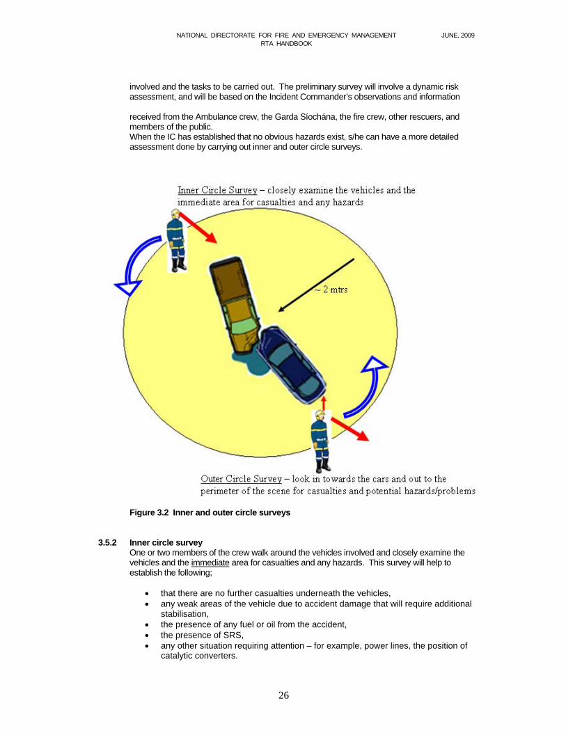
involved and the tasks to be carried out. The preliminary survey will involve a dynamic risk assessment, and will be based on the Incident Commander’s observations and information received from the Ambulance crew, the Garda Síochána, the fire crew, other rescuers, and members of the public. When the IC has established that no obvious hazards exist, s/he can have a more detailed assessment done by carrying out inner and outer circle surveys.
Figure 3.2 Inner and outer circle surveys 3.5.2 Inner circle survey
One or two members of the crew walk around the vehicles involved and closely examine the vehicles and the immediate area for casualties and any hazards. This survey will help to establish the following;
that there are no further casualties underneath the vehicles, any weak areas of the vehicle due to accident damage that will require additional
stabilisation, the presence of any fuel or oil from the accident, the presence of SRS, any other situation requiring attention – for example, power lines, the position of
catalytic converters.
NATIONAL DIRECTORATE FOR FIRE AND EMERGENCY MANAGEMENT JUNE, 2009 RTA HANDBOOK
27
3.5.3 Outer circle survey
One or two members of the crew walk completely around the vehicle. They look in towards the car and out to the perimeter of the scene, checking for casualties, obstructions, hazards, and any potential problems while remaining a few metres away from the vehicle. As soon as resources permit, the Incident Commander should have a thorough search done of the entire area surrounding the incident.
3.5.4 Factors to consider When the Incident Commander is carrying out an appraisal of the scene, there are a number of factors to consider before drawing up a plan of action. These factors would include
Whether further assistance is required
Dealing with fires
Special risks – for example, traffic, hazardous materials
Casualties – the location, entrapment, number, priority
Level of medical help required, ambulances paramedics or medical team.
Whether further special equipment or appliances are necessary, including heavy lifting gear, to extricate casualties.
Environmental issues, such as run-off to adjacent waterways
Garda investigations which may include forensic work.
3.6 Plan of action
The overall plan given in Section 3.1 above will be suitable for most road traffic accidents. The Incident Commander will have begun to put this plan into operation en route to the incident, by allocating roles to the crew which would include scene safety, early casualty contact, inner and outer circle surveys, vehicle stability, tool staging and tool operation.
Based on the information gathered from the appraisal of the scene, and keeping the overall plan in mind, the Incident Commander will draw up a logical detailed plan of action for the controlled release of the casualty. The crew will be briefed on the plan so that each of them is aware of the procedure to be followed. The Incident Commander will also have a plan B in mind, in case the original plan runs into complications, and immediate release is necessary.
3.7 Crew roles
As stated in Section 1, the golden hour concept highlights the need for an efficient rescue with a minimum extrication time. The team approach has been identified as a method of reducing extrication times through better organization and a methodical approach to extrication. The team approach applies to the overall team, comprising all emergency services and also to the fire crew as a team in itself.
NATIONAL DIRECTORATE FOR FIRE AND EMERGENCY MANAGEMENT JUNE, 2009 RTA HANDBOOK
28
Preplanning for a road traffic accident has also been acknowledged as a method of improving efficiency and reducing extrication times. Part of this preplanning entails training of the crew and identifying the various roles involved. Each member of the crew should be able to perform any of the roles. This gives the Incident Commander more flexibility and allows a change around if necessary. It also means that every crew member is aware of the work of the other members of the crew and can assist as necessary. Practically, however, some firefighters will be more proficient at some roles than others, and the Incident Commander will bear this in mind when assigning roles en route to an incident. The minimum crew on an appliance which would be expected to respond to an RTA would be four crew members, plus the crew commander. An example is given in the table below of how the various operations could be carried out with this minimum crew. When more crew, or other crews, are available, the workload can be shared out accordingly. The critical point is that each crew member knows and understands her/his role on arrival at the scene.
Crew Member Function Tool Operators (2no.)
Inner circle survey, stability, glass management, operate tools
Driver
Lay out firefighting gear, put out signs, outer circle survey, set up tool staging area, disconnect battery, assist casualty carer and tool operators
Casualty Carer
Assess casualty, deal with immediate needs, keep IC up to date on casualty’s condition, keep casualty informed, assist HSE personnel
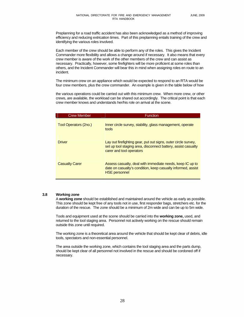
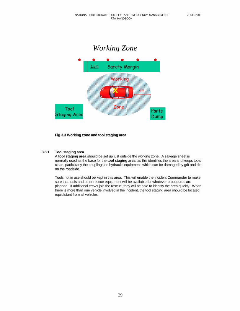
3.8 Working zone A working zone should be established and maintained around the vehicle as early as possible. This zone should be kept free of any tools not in use, first responder bags, stretchers etc. for the duration of the rescue. The zone should be a minimum of 2m wide and can be up to 5m wide. Tools and equipment used at the scene should be carried into the working zone, used, and returned to the tool staging area. Personnel not actively working on the rescue should remain outside this zone until required. The working zone is a theoretical area around the vehicle that should be kept clear of debris, idle tools, spectators and non-essential personnel. The area outside the working zone, which contains the tool staging area and the parts dump, should be kept clear of all personnel not involved in the rescue and should be cordoned off if necessary.
NATIONAL DIRECTORATE FOR FIRE AND EMERGENCY MANAGEMENT JUNE, 2009 RTA HANDBOOK
29
2m2m
ToolStaging Area
X
Working Zone
Working
ZoneParts Dump
Safety Margin1.2m Safety Margin1.2m
Fig 3.3 Working zone and tool staging area
3.8.1 Tool staging area A tool staging area should be set up just outside the working zone. A salvage sheet is normally used as the base for the tool staging area, as this identifies the area and keeps tools clean, particularly the couplings on hydraulic equipment, which can be damaged by grit and dirt on the roadside. Tools not in use should be kept in this area. This will enable the Incident Commander to make sure that tools and other rescue equipment will be available for whatever procedures are planned. If additional crews join the rescue, they will be able to identify the area quickly. When there is more than one vehicle involved in the incident, the tool staging area should be located equidistant from all vehicles.

NATIONAL DIRECTORATE FOR FIRE AND EMERGENCY MANAGEMENT JUNE, 2009 RTA HANDBOOK
30
Figure 3.4 3.8.2 Parts dump
Any material removed from the vehicle should be taken out of the working zone in order to create a working area free from any obstructions. This material should be placed in the area designated by the Incident Commander as the parts dump. However, any debris from the vehicle that could form part of the evidence the Garda Síochána will use in their investigation should be left in place, provided it is not an obvious danger to those working in the working zone.
3.9 Safety margin Safety zones around the scene of an accident protect emergency personnel and others at the incident and ensure a safe system of working can provided. The fend-off appliances provide a longitudinal safety margin for the scene. A lateral safety margin is also required between the working zone and any passing traffic. This lateral safety margin is measured from the back of the cones to the working zone and it should be 1.2m wide. If it is not possible to provide this safety margin between the working zone (which should be a minimum of 2m wide) and passing traffic, the traffic should be stopped.
3.10 Motorway and dual carriageway based incidents Motorway and dual carriageway based incidents by their very nature pose a greater threat to fire & rescue service operations. Traffic speeds are considerably higher and traffic volumes generally much heavier. In the event of a carriageway being closed there is a considerable risk of rear-end collisions on the affected carriageway. There is also a considerable risk of collisions on the unaffected carriageway due to onlookers rubber necking. This can lead to a total closure of the motorway or dual carriageway, leading to gridlock and considerable difficulties for fire & rescue service and other emergency services accessing the incident. Locating the incident can be difficult as the call originator may be unsure of their exact location and direction of travel. Locators such as direction of travel (northbound, eastbound, etc., along with any other relevant information – for example, just beyond Junction 15 on the M7, northbound) should be obtained where possible before going mobile to the incident. This may significantly reduce travel time to the incident, if the correct location is obtained prior to leaving the fire station.

NATIONAL DIRECTORATE FOR FIRE AND EMERGENCY MANAGEMENT JUNE, 2009 RTA HANDBOOK
31
Pre-determined attendance (PDA) The recommended minimum PDA for all motorway and dual carriageway based incidents is two appliances plus any other available fire & rescue service vehicles. Unless the exact location of the incident is known one appliance should proceed to the incident on the reported carriageway from a point before the incident and the second appliance on the opposite carriageway from a point beyond the incident traveling towards the incident on the opposite carriageway. This then maximises the possibility of locating the incident in the shortest possible time. Approaching the incident On the carriageway involved: Due to the high speeds of traffic on a motorway or dual carriageway, there is a greater possibility of a rear-end collision if the fire & rescue service stop suddenly at the incident. In order to reduce this risk, a form of rolling roadblock should be used where one or more appliances occupy some or all of the lanes approaching the incident and from approximately 1 km from the reported incident gradually reduce speed. This has the effect of slowing down following traffic. In addition, it also reduces the risk of colliding with anyone who may be out of their vehicles at the incident. From the unaffected carriageway: The majority of motorways and dual carriageways now have safety barriers to separate the carriageways and to prevent cross-over collisions. At intervals on the motorway and dual carriageway there may be emergency cross-over points marked by red and white poles. It is not recommended that these cross-over points be used as the appliance is slowing/stopping in the fast lane and similarly pulling out into traffic on the fast lane. They should only be used under strict Garda Síochána supervision. Ideally, all appliances should travel to the next junction and proceed back up the affected carriageway to the incident. If the central reserve barrier is of the steel wire rope variety, specific training in de-tensioning and demounting of this steel wire rope barrier should be obtained from the local authority. Where junctions are greater than 8km apart, the National Roads Authority are constructing graveled emergency services access points to provide a cross over facility. Appliances should have the appropriate means to open these emergency access points. These access points should be used as necessary. Crew safety All personnel should dismount from the appliance on the side away from the traffic. All personnel should be aware of the danger from fast moving traffic and on no account should either enter or attempt to cross a lane open to traffic. Special care and attention should be paid when obtaining equipment from lockers on the traffic side of the appliance. Personnel should not turn their back to oncoming traffic. Personal protective equipment High visibility clothing conforming to EN471 class 3 should be worn. (sleeved high-viz jackets) along with standard turn out gear. Fend-off Initially, appliances should fend-off at a distance sufficiently far back from the incident to provide protection to the working circle in the event of a collision but close enough so that equipment can be obtained easily. A distance of 15m to 20m is recommended initially. As additional appliances arrive at the incident, they should be deployed in the fend-off position approximately 50 m back from the incident to provide additional protection. Once sufficient appliances are in the fend off position, then all further responding appliances should proceed beyond the incident and park in-line on the hard shoulder or outside lane as appropriate to ensure that there is no need for personnel to cross a live lane in order to obtain equipment. The fend off position should cover the affected lane and one lane either side of the affected lane, i.e. incident in hard shoulder, cover hard shoulder and lane 1. Under no circumstances should an island be created whereby vehicles are permitted to pass the incident on two sides.

NATIONAL DIRECTORATE FOR FIRE AND EMERGENCY MANAGEMENT JUNE, 2009 RTA HANDBOOK
32
Cones Where possible, 1m road cones should be used, accompanied by blue lights as necessary. There should be at least 100m of tapering cones per lane affected. i.e. lane 1 only affected, coning begins 100m back from the incident, where lanes 1 & 2 are affected coning begins 200m back from the incident. Consideration should be given to carry sufficient cones (20 to 30) on a trailer or 4x4 vehicle. Signage Where possible, advance warning signs should be placed in the hard shoulder or centre median at 900m, 600m, and 300m back from the incident. It is recommended that the standard pop up sign is used at 900m, a large trailer mounted sign used at 600m where available and a standard pop-up sign used again at 300m, as illustrated at figure 3.5.
900 m 600 m 300 m Figure 3.5
3.11 Confirm progress, monitor and evaluate
During the rescue, it is important that the Incident Commander should keep the momentum going to ensure that the objective of getting the casualty released safely in the minimum time will be achieved. The Incident Commander should ensure that the extrication is going according to plan and should liaise with HSE personnel to confirm that the original priorities remain unchanged. This will allow the Incident Commander to look ahead and to ensure that personnel and equipment are in place for the next stage of the plan. It is essential also that all safety aspects are regularly checked and that the risk assessment is updated, particularly where passing traffic is involved.
3.12 Casualty transfer No injured person should be moved until assessed by an appropriately trained person,
unless the casualty or rescuers are in immediate danger. The objective should be to provide sufficient space for stabilization and immobilisation of the casualty, work to free the trapped person, leading to a safe removal from the scene. Where casualties are being handled by fire service personnel, this should be in accordance with correct manual handling techniques.
NATIONAL DIRECTORATE FOR FIRE AND EMERGENCY MANAGEMENT JUNE, 2009 RTA HANDBOOK
33
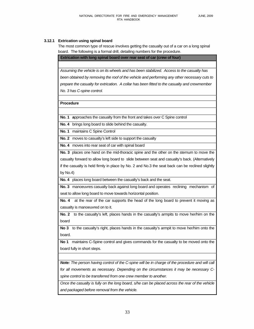
3.12.1 Extrication using spinal board The most common type of rescue involves getting the casualty out of a car on a long spinal
board. The following is a formal drill, detailing numbers for the procedure.
Extrication with long spinal board over rear seat of car (crew of four)
Assuming the vehicle is on its wheels and has been stabilized. Access to the casualty has
been obtained by removing the roof of the vehicle and performing any other necessary cuts to
prepare the casualty for extrication. A collar has been fitted to the casualty and crewmember
No. 3 has C-spine control.
Procedure
No. 1 approaches the casualty from the front and takes over C Spine control
No. 4 brings long board to slide behind the casualty.
No. 1 maintains C Spine Control
No. 2 moves to casualty’s left side to support the casualty
No. 4 moves into rear seat of car with spinal board
No. 3 places one hand on the mid-thoracic spine and the other on the sternum to move the
casualty forward to allow long board to slide between seat and casualty’s back. (Alternatively
if the casualty is held firmly in place by No. 2 and No.3 the seat back can be reclined slightly
by No.4)
No. 4 places long board between the casualty’s back and the seat.
No. 3 manoeuvres casualty back against long board and operates reclining mechanism of
seat to allow long board to move towards horizontal position.
No. 4 at the rear of the car supports the head of the long board to prevent it moving as
casualty is manoeuvred on to it.
No. 2 to the casualty’s left, places hands in the casualty’s armpits to move her/him on the
board
No 3 to the casualty’s right, places hands in the casualty’s armpit to move her/him onto the
board.
No 1 maintains C-Spine control and gives commands for the casualty to be moved onto the
board fully in short steps.
Note: The person having control of the C-spine will be in charge of the procedure and will call
for all movements as necessary. Depending on the circumstances it may be necessary C-
spine control to be transferred from one crew member to another.
Once the casualty is fully on the long board, s/he can be placed across the rear of the vehicle
and packaged before removal from the vehicle.
NATIONAL DIRECTORATE FOR FIRE AND EMERGENCY MANAGEMENT JUNE, 2009 RTA HANDBOOK
34
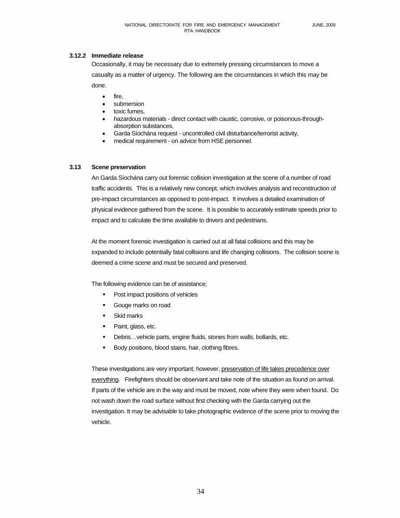
3.12.2 Immediate release
Occasionally, it may be necessary due to extremely pressing circumstances to move a
casualty as a matter of urgency. The following are the circumstances in which this may be
done.
fire, submersion toxic fumes, hazardous materials - direct contact with caustic, corrosive, or poisonous-through-
absorption substances, Garda Síochána request - uncontrolled civil disturbance/terrorist activity, medical requirement - on advice from HSE personnel.
3.13 Scene preservation
An Garda Síochána carry out forensic collision investigation at the scene of a number of road
traffic accidents. This is a relatively new concept, which involves analysis and reconstruction of
pre-impact circumstances as opposed to post-impact. It involves a detailed examination of
physical evidence gathered from the scene. It is possible to accurately estimate speeds prior to
impact and to calculate the time available to drivers and pedestrians.
At the moment forensic investigation is carried out at all fatal collisions and this may be
expanded to include potentially fatal collisions and life changing collisions. The collision scene is
deemed a crime scene and must be secured and preserved.
The following evidence can be of assistance;
Post impact positions of vehicles
Gouge marks on road
Skid marks
Paint, glass, etc.
Debris…vehicle parts, engine fluids, stones from walls, bollards, etc.
Body positions, blood stains, hair, clothing fibres.
These investigations are very important; however, preservation of life takes precedence over
everything. Firefighters should be observant and take note of the situation as found on arrival.
If parts of the vehicle are in the way and must be moved, note where they were when found. Do
not wash down the road surface without first checking with the Garda carrying out the
investigation. It may be advisable to take photographic evidence of the scene prior to moving the
vehicle.

NATIONAL DIRECTORATE FOR FIRE AND EMERGENCY MANAGEMENT JUNE, 2009 RTA HANDBOOK
35
3.14 Make-up
Responsibility for tidying up the scene and restoring traffic flows rests with An Garda
Síochána, but fire brigade personnel should assist with whatever resources are available. It is
essential that the scene be left in a safe manner, whether this means providing signs, cones
taping off etc. or handing over to the appropriate personnel. It is a matter for the local authority Roads Section to decide whether a road is safe for traffic or
otherwise.
Normal post-incident make-up procedures apply, all equipment should be cleaned and properly stored, and the appliance made ready for the next operation.
3.15 De-brief
The Incident Commander should conduct an operational de-brief at the scene, where appropriate. Debriefing is helpful in appraising performance, and identifying areas requiring additional preparation and training. What went right? What went wrong? How can brigades improve on procedures? What lessons were learned? Road Traffic Accidents can be traumatic for responding firefighters. The IC should be conscious of the impact this may have on the crew. An immediate discussion session on this aspect following return to the station and reviewing the incident may be beneficial to staff. The crew may need to be reminded of the arrangements that are in place in their authority for Critical Incident Stress Management. The Incident Commander should complete the standard report in respect of the incident, and any special reports required.
3.16 Standard operating procedures.
Standard operating procedures are generally produced to assist an Incident Commander in
his/her work by acting as an aide memoire in formulating a plan for whatever situation is
encountered. Fire authorities may wish to consider whether the procedure below is suitable for
local circumstances, and may amend, add or exclude items as appropriate. Additionally, not all
of the actions listed in the procedure will be necessary in any given situation and the Incident
Commander should exercise her/his own judgement of actions to be taken in light of the
circumstances.
It is assumed in the procedure below that some of the actions will be taken simultaneously and
that the risk assessment may alter the sequence shown.

NATIONAL DIRECTORATE FOR FIRE AND EMERGENCY MANAGEMENT JUNE, 2009 RTA HANDBOOK
36
STANDARD OPERATING PROCEDURE
Mobilise as PDA Request Garda Síochána attendance and confirm HSE are aware
of incident.
Allocate roles to crew members
Arrival Careful approach, park in fend-off position(s).
Address scene safety.
Appraisal Do a preliminary survey including a risk assessment.
Liaise with HSE and Garda Síochána.
Have Inner Circle survey and Outer Circle survey done.
Plan of action Prepare a plan of action for a controlled release of casualty and
have a plan for immediate release also.
Brief crew.
Casualty contact Make early contact with casualty.
Working zone Establish a working zone and a tool staging area.
Stability Stabilize the vehicle
Casualty survey Casualty carer to carry out a primary casualty survey including
airway, breathing and circulation and C-spine immobilization as
necessary.
Create space Create space around the casualty for treatment by HSE and create
space for extrication.
Confirm progress Confirm progress and prepare for extrication.
Update risk assessment regularly.
Remove casualty Remove casualty from vehicle and transfer to ambulance.
Make-up Be aware of Garda Síochána requirements for scene preservation.
Leave the scene in a safe condition.
De-brief Carry out de-brief.
Make crew aware of availability of CISM.
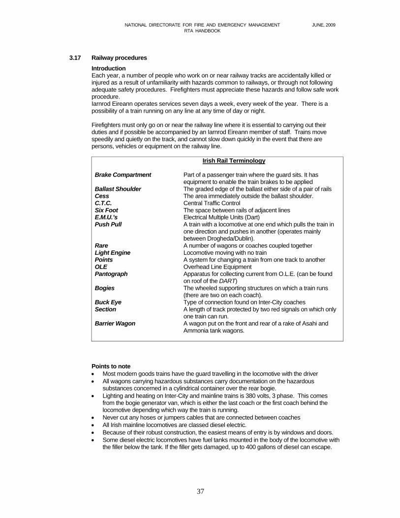
NATIONAL DIRECTORATE FOR FIRE AND EMERGENCY MANAGEMENT JUNE, 2009 RTA HANDBOOK
37
3.17 Railway procedures
Introduction Each year, a number of people who work on or near railway tracks are accidentally killed or injured as a result of unfamiliarity with hazards common to railways, or through not following adequate safety procedures. Firefighters must appreciate these hazards and follow safe work procedure. Iarnrod Eireann operates services seven days a week, every week of the year. There is a possibility of a train running on any line at any time of day or night.
Firefighters must only go on or near the railway line where it is essential to carrying out their duties and if possible be accompanied by an Iarnrod Eireann member of staff. Trains move speedily and quietly on the track, and cannot slow down quickly in the event that there are persons, vehicles or equipment on the railway line.
Irish Rail Terminology
Brake Compartment Part of a passenger train where the guard sits. It has
equipment to enable the train brakes to be applied Ballast Shoulder The graded edge of the ballast either side of a pair of rails Cess The area immediately outside the ballast shoulder. C.T.C. Central Traffic Control Six Foot The space between rails of adjacent lines E.M.U.’s Electrical Multiple Units (Dart) Push Pull A train with a locomotive at one end which pulls the train in
one direction and pushes in another (operates mainly between Drogheda/Dublin).
Rare A number of wagons or coaches coupled together Light Engine Locomotive moving with no train Points A system for changing a train from one track to another OLE Overhead Line Equipment Pantograph Apparatus for collecting current from O.L.E. (can be found
on roof of the DART) Bogies The wheeled supporting structures on which a train runs
(there are two on each coach). Buck Eye Type of connection found on Inter-City coaches Section A length of track protected by two red signals on which only
one train can run. Barrier Wagon A wagon put on the front and rear of a rake of Asahi and
Ammonia tank wagons.
Points to note Most modern goods trains have the guard travelling in the locomotive with the driver All wagons carrying hazardous substances carry documentation on the hazardous
substances concerned in a cylindrical container over the rear bogie. Lighting and heating on Inter-City and mainline trains is 380 volts, 3 phase. This comes
from the bogie generator van, which is either the last coach or the first coach behind the locomotive depending which way the train is running.
Never cut any hoses or jumpers cables that are connected between coaches All Irish mainline locomotives are classed diesel electric. Because of their robust construction, the easiest means of entry is by windows and doors. Some diesel electric locomotives have fuel tanks mounted in the body of the locomotive with
the filler below the tank. If the filler gets damaged, up to 400 gallons of diesel can escape.
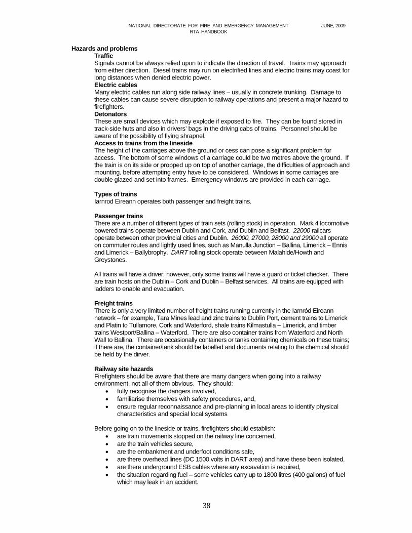
NATIONAL DIRECTORATE FOR FIRE AND EMERGENCY MANAGEMENT JUNE, 2009 RTA HANDBOOK
38
Hazards and problems Traffic Signals cannot be always relied upon to indicate the direction of travel. Trains may approach from either direction. Diesel trains may run on electrified lines and electric trains may coast for long distances when denied electric power. Electric cables Many electric cables run along side railway lines – usually in concrete trunking. Damage to these cables can cause severe disruption to railway operations and present a major hazard to firefighters. Detonators These are small devices which may explode if exposed to fire. They can be found stored in track-side huts and also in drivers’ bags in the driving cabs of trains. Personnel should be aware of the possibility of flying shrapnel. Access to trains from the lineside The height of the carriages above the ground or cess can pose a significant problem for access. The bottom of some windows of a carriage could be two metres above the ground. If the train is on its side or propped up on top of another carriage, the difficulties of approach and mounting, before attempting entry have to be considered. Windows in some carriages are double glazed and set into frames. Emergency windows are provided in each carriage.
Types of trains Iarnrod Eireann operates both passenger and freight trains. Passenger trains There are a number of different types of train sets (rolling stock) in operation. Mark 4 locomotive powered trains operate between Dublin and Cork, and Dublin and Belfast. 22000 railcars operate between other provincial cities and Dublin. 26000, 27000, 28000 and 29000 all operate on commuter routes and lightly used lines, such as Manulla Junction – Ballina, Limerick – Ennis and Limerick – Ballybrophy. DART rolling stock operate between Malahide/Howth and Greystones. All trains will have a driver; however, only some trains will have a guard or ticket checker. There are train hosts on the Dublin – Cork and Dublin – Belfast services. All trains are equipped with ladders to enable and evacuation. Freight trains There is only a very limited number of freight trains running currently in the Iarnród Eireann network – for example, Tara Mines lead and zinc trains to Dublin Port, cement trains to Limerick and Platin to Tullamore, Cork and Waterford, shale trains Kilmastulla – Limerick, and timber trains Westport/Ballina – Waterford. There are also container trains from Waterford and North Wall to Ballina. There are occasionally containers or tanks containing chemicals on these trains; if there are, the container/tank should be labelled and documents relating to the chemical should be held by the dirver. Railway site hazards Firefighters should be aware that there are many dangers when going into a railway environment, not all of them obvious. They should:
fully recognise the dangers involved, familiarise themselves with safety procedures, and, ensure regular reconnaissance and pre-planning in local areas to identify physical
characteristics and special local systems Before going on to the lineside or trains, firefighters should establish:
are train movements stopped on the railway line concerned, are the train vehicles secure, are the embankment and underfoot conditions safe, are there overhead lines (DC 1500 volts in DART area) and have these been isolated, are there underground ESB cables where any excavation is required, the situation regarding fuel – some vehicles carry up to 1800 litres (400 gallons) of fuel
which may leak in an accident.
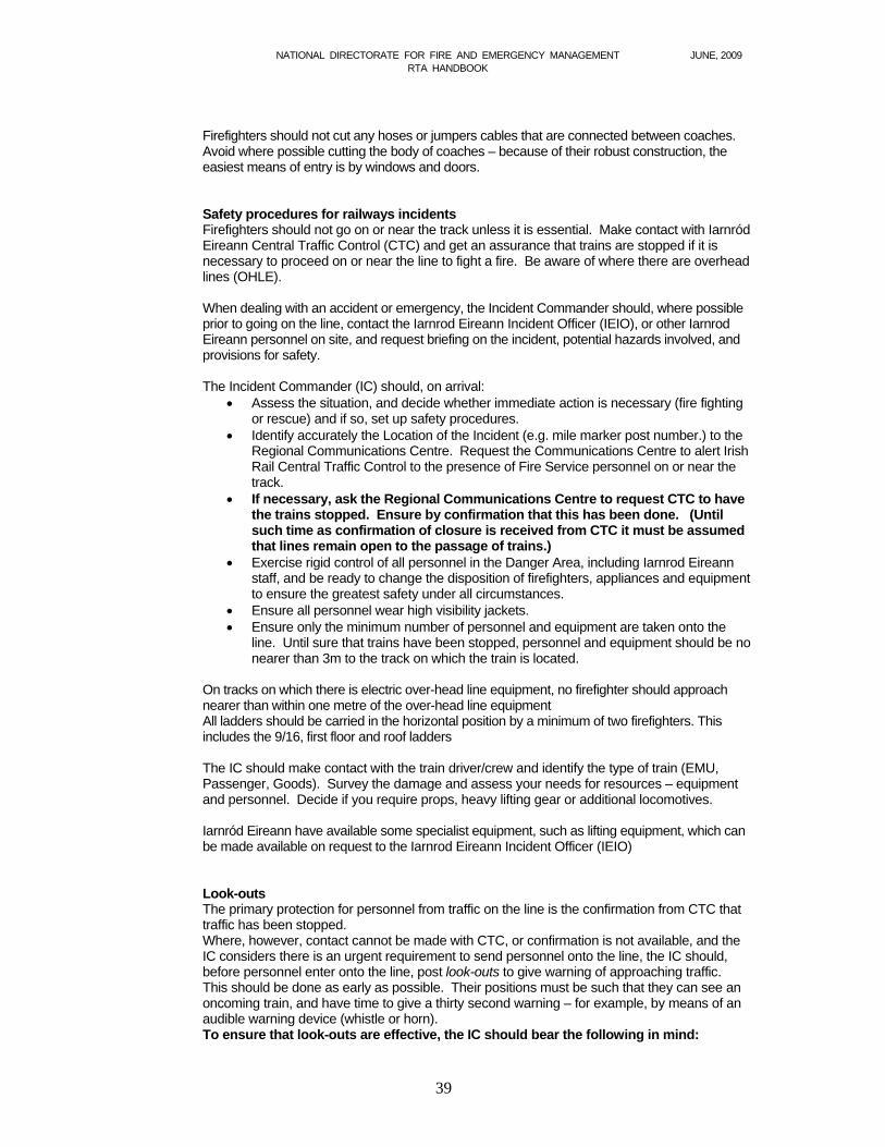
NATIONAL DIRECTORATE FOR FIRE AND EMERGENCY MANAGEMENT JUNE, 2009 RTA HANDBOOK
39
Firefighters should not cut any hoses or jumpers cables that are connected between coaches. Avoid where possible cutting the body of coaches – because of their robust construction, the easiest means of entry is by windows and doors. Safety procedures for railways incidents Firefighters should not go on or near the track unless it is essential. Make contact with Iarnród Eireann Central Traffic Control (CTC) and get an assurance that trains are stopped if it is necessary to proceed on or near the line to fight a fire. Be aware of where there are overhead lines (OHLE). When dealing with an accident or emergency, the Incident Commander should, where possible prior to going on the line, contact the Iarnrod Eireann Incident Officer (IEIO), or other Iarnrod Eireann personnel on site, and request briefing on the incident, potential hazards involved, and provisions for safety. The Incident Commander (IC) should, on arrival:
Assess the situation, and decide whether immediate action is necessary (fire fighting or rescue) and if so, set up safety procedures.
Identify accurately the Location of the Incident (e.g. mile marker post number.) to the Regional Communications Centre. Request the Communications Centre to alert Irish Rail Central Traffic Control to the presence of Fire Service personnel on or near the track.
If necessary, ask the Regional Communications Centre to request CTC to have the trains stopped. Ensure by confirmation that this has been done. (Until such time as confirmation of closure is received from CTC it must be assumed that lines remain open to the passage of trains.)
Exercise rigid control of all personnel in the Danger Area, including Iarnrod Eireann staff, and be ready to change the disposition of firefighters, appliances and equipment to ensure the greatest safety under all circumstances.
Ensure all personnel wear high visibility jackets. Ensure only the minimum number of personnel and equipment are taken onto the
line. Until sure that trains have been stopped, personnel and equipment should be no nearer than 3m to the track on which the train is located.
On tracks on which there is electric over-head line equipment, no firefighter should approach nearer than within one metre of the over-head line equipment
All ladders should be carried in the horizontal position by a minimum of two firefighters. This includes the 9/16, first floor and roof ladders The IC should make contact with the train driver/crew and identify the type of train (EMU, Passenger, Goods). Survey the damage and assess your needs for resources – equipment and personnel. Decide if you require props, heavy lifting gear or additional locomotives. Iarnród Eireann have available some specialist equipment, such as lifting equipment, which can be made available on request to the Iarnrod Eireann Incident Officer (IEIO)
Look-outs The primary protection for personnel from traffic on the line is the confirmation from CTC that
traffic has been stopped. Where, however, contact cannot be made with CTC, or confirmation is not available, and the
IC considers there is an urgent requirement to send personnel onto the line, the IC should, before personnel enter onto the line, post look-outs to give warning of approaching traffic.
This should be done as early as possible. Their positions must be such that they can see an oncoming train, and have time to give a thirty second warning – for example, by means of an audible warning device (whistle or horn). To ensure that look-outs are effective, the IC should bear the following in mind:
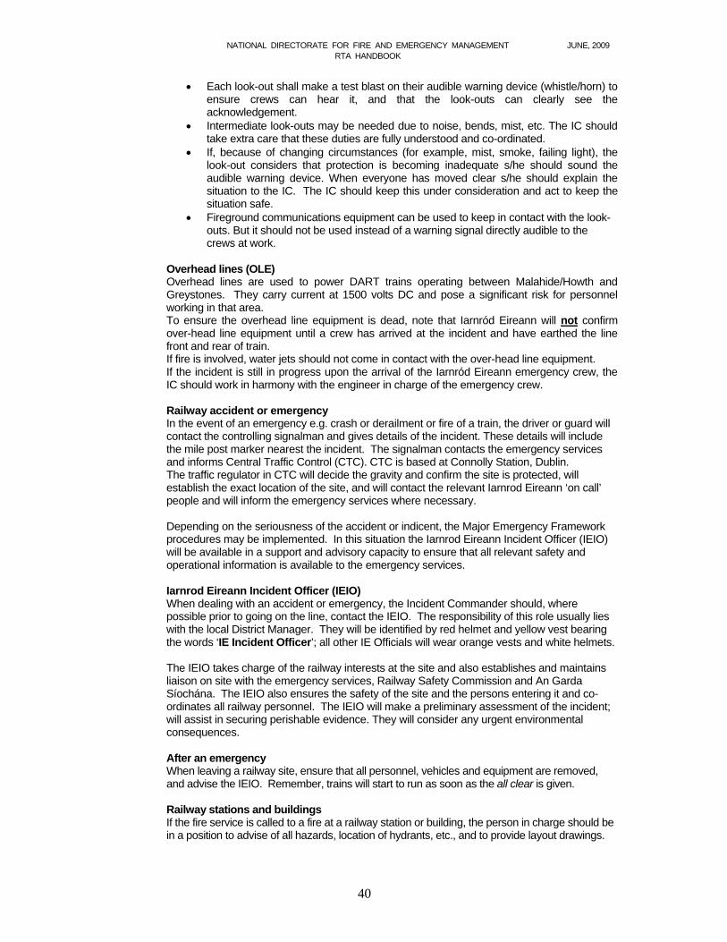
NATIONAL DIRECTORATE FOR FIRE AND EMERGENCY MANAGEMENT JUNE, 2009 RTA HANDBOOK
40
Each look-out shall make a test blast on their audible warning device (whistle/horn) to ensure crews can hear it, and that the look-outs can clearly see the acknowledgement.
Intermediate look-outs may be needed due to noise, bends, mist, etc. The IC should take extra care that these duties are fully understood and co-ordinated.
If, because of changing circumstances (for example, mist, smoke, failing light), the look-out considers that protection is becoming inadequate s/he should sound the audible warning device. When everyone has moved clear s/he should explain the situation to the IC. The IC should keep this under consideration and act to keep the situation safe.
Fireground communications equipment can be used to keep in contact with the look-outs. But it should not be used instead of a warning signal directly audible to the crews at work.
Overhead lines (OLE) Overhead lines are used to power DART trains operating between Malahide/Howth and Greystones. They carry current at 1500 volts DC and pose a significant risk for personnel working in that area. To ensure the overhead line equipment is dead, note that Iarnród Eireann will not confirm over-head line equipment until a crew has arrived at the incident and have earthed the line front and rear of train. If fire is involved, water jets should not come in contact with the over-head line equipment. If the incident is still in progress upon the arrival of the Iarnród Eireann emergency crew, the IC should work in harmony with the engineer in charge of the emergency crew. Railway accident or emergency In the event of an emergency e.g. crash or derailment or fire of a train, the driver or guard will contact the controlling signalman and gives details of the incident. These details will include the mile post marker nearest the incident. The signalman contacts the emergency services and informs Central Traffic Control (CTC). CTC is based at Connolly Station, Dublin. The traffic regulator in CTC will decide the gravity and confirm the site is protected, will establish the exact location of the site, and will contact the relevant Iarnrod Eireann ‘on call’ people and will inform the emergency services where necessary. Depending on the seriousness of the accident or indicent, the Major Emergency Framework procedures may be implemented. In this situation the Iarnrod Eireann Incident Officer (IEIO) will be available in a support and advisory capacity to ensure that all relevant safety and operational information is available to the emergency services. Iarnrod Eireann Incident Officer (IEIO) When dealing with an accident or emergency, the Incident Commander should, where possible prior to going on the line, contact the IEIO. The responsibility of this role usually lies with the local District Manager. They will be identified by red helmet and yellow vest bearing the words ‘IE Incident Officer’; all other IE Officials will wear orange vests and white helmets. The IEIO takes charge of the railway interests at the site and also establishes and maintains liaison on site with the emergency services, Railway Safety Commission and An Garda Síochána. The IEIO also ensures the safety of the site and the persons entering it and co-ordinates all railway personnel. The IEIO will make a preliminary assessment of the incident; will assist in securing perishable evidence. They will consider any urgent environmental consequences. After an emergency When leaving a railway site, ensure that all personnel, vehicles and equipment are removed, and advise the IEIO. Remember, trains will start to run as soon as the all clear is given.
Railway stations and buildings If the fire service is called to a fire at a railway station or building, the person in charge should be in a position to advise of all hazards, location of hydrants, etc., and to provide layout drawings.
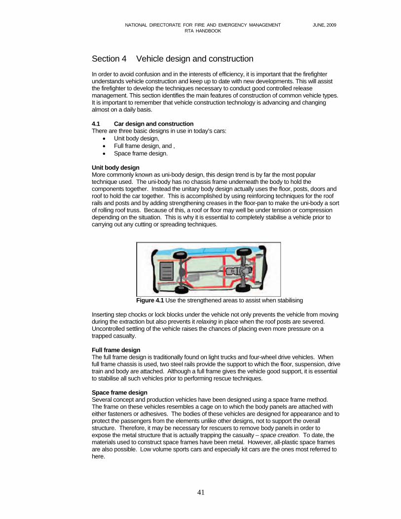
NATIONAL DIRECTORATE FOR FIRE AND EMERGENCY MANAGEMENT JUNE, 2009 RTA HANDBOOK
41
Section 4 Vehicle design and construction
In order to avoid confusion and in the interests of efficiency, it is important that the firefighter understands vehicle construction and keep up to date with new developments. This will assist the firefighter to develop the techniques necessary to conduct good controlled release management. This section identifies the main features of construction of common vehicle types. It is important to remember that vehicle construction technology is advancing and changing almost on a daily basis.
4.1 Car design and construction There are three basic designs in use in today’s cars:
Unit body design, Full frame design, and , Space frame design.
Unit body design More commonly known as uni-body design, this design trend is by far the most popular technique used. The uni-body has no chassis frame underneath the body to hold the components together. Instead the unitary body design actually uses the floor, posts, doors and roof to hold the car together. This is accomplished by using reinforcing techniques for the roof rails and posts and by adding strengthening creases in the floor-pan to make the uni-body a sort of rolling roof truss. Because of this, a roof or floor may well be under tension or compression depending on the situation. This is why it is essential to completely stabilise a vehicle prior to carrying out any cutting or spreading techniques.
Figure 4.1 Use the strengthened areas to assist when stabilising
Inserting step chocks or lock blocks under the vehicle not only prevents the vehicle from moving during the extraction but also prevents it relaxing in place when the roof posts are severed. Uncontrolled settling of the vehicle raises the chances of placing even more pressure on a trapped casualty. Full frame design The full frame design is traditionally found on light trucks and four-wheel drive vehicles. When full frame chassis is used, two steel rails provide the support to which the floor, suspension, drive train and body are attached. Although a full frame gives the vehicle good support, it is essential to stabilise all such vehicles prior to performing rescue techniques. Space frame design Several concept and production vehicles have been designed using a space frame method. The frame on these vehicles resembles a cage on to which the body panels are attached with either fasteners or adhesives. The bodies of these vehicles are designed for appearance and to protect the passengers from the elements unlike other designs, not to support the overall structure. Therefore, it may be necessary for rescuers to remove body panels in order to expose the metal structure that is actually trapping the casualty – space creation. To date, the materials used to construct space frames have been metal. However, all-plastic space frames are also possible. Low volume sports cars and especially kit cars are the ones most referred to here.
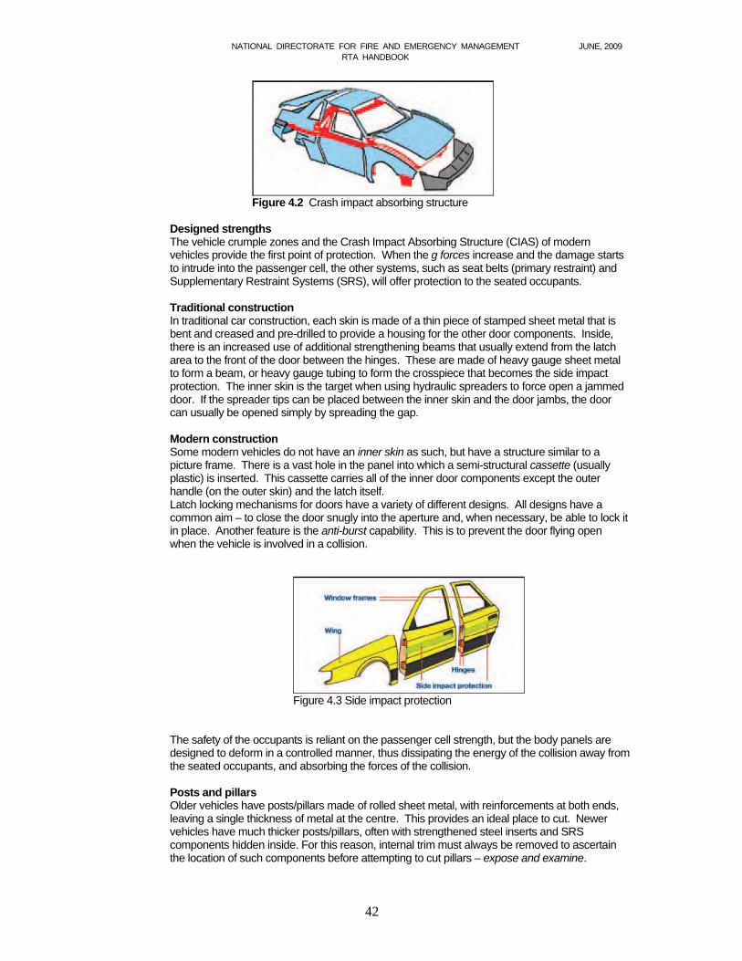
NATIONAL DIRECTORATE FOR FIRE AND EMERGENCY MANAGEMENT JUNE, 2009 RTA HANDBOOK
42
Figure 4.2 Crash impact absorbing structure Designed strengths The vehicle crumple zones and the Crash Impact Absorbing Structure (CIAS) of modern vehicles provide the first point of protection. When the g forces increase and the damage starts to intrude into the passenger cell, the other systems, such as seat belts (primary restraint) and Supplementary Restraint Systems (SRS), will offer protection to the seated occupants. Traditional construction In traditional car construction, each skin is made of a thin piece of stamped sheet metal that is bent and creased and pre-drilled to provide a housing for the other door components. Inside, there is an increased use of additional strengthening beams that usually extend from the latch area to the front of the door between the hinges. These are made of heavy gauge sheet metal to form a beam, or heavy gauge tubing to form the crosspiece that becomes the side impact protection. The inner skin is the target when using hydraulic spreaders to force open a jammed door. If the spreader tips can be placed between the inner skin and the door jambs, the door can usually be opened simply by spreading the gap. Modern construction Some modern vehicles do not have an inner skin as such, but have a structure similar to a picture frame. There is a vast hole in the panel into which a semi-structural cassette (usually plastic) is inserted. This cassette carries all of the inner door components except the outer handle (on the outer skin) and the latch itself. Latch locking mechanisms for doors have a variety of different designs. All designs have a common aim – to close the door snugly into the aperture and, when necessary, be able to lock it in place. Another feature is the anti-burst capability. This is to prevent the door flying open when the vehicle is involved in a collision.
Figure 4.3 Side impact protection
The safety of the occupants is reliant on the passenger cell strength, but the body panels are designed to deform in a controlled manner, thus dissipating the energy of the collision away from the seated occupants, and absorbing the forces of the collision. Posts and pillars Older vehicles have posts/pillars made of rolled sheet metal, with reinforcements at both ends, leaving a single thickness of metal at the centre. This provides an ideal place to cut. Newer vehicles have much thicker posts/pillars, often with strengthened steel inserts and SRS components hidden inside. For this reason, internal trim must always be removed to ascertain the location of such components before attempting to cut pillars – expose and examine.
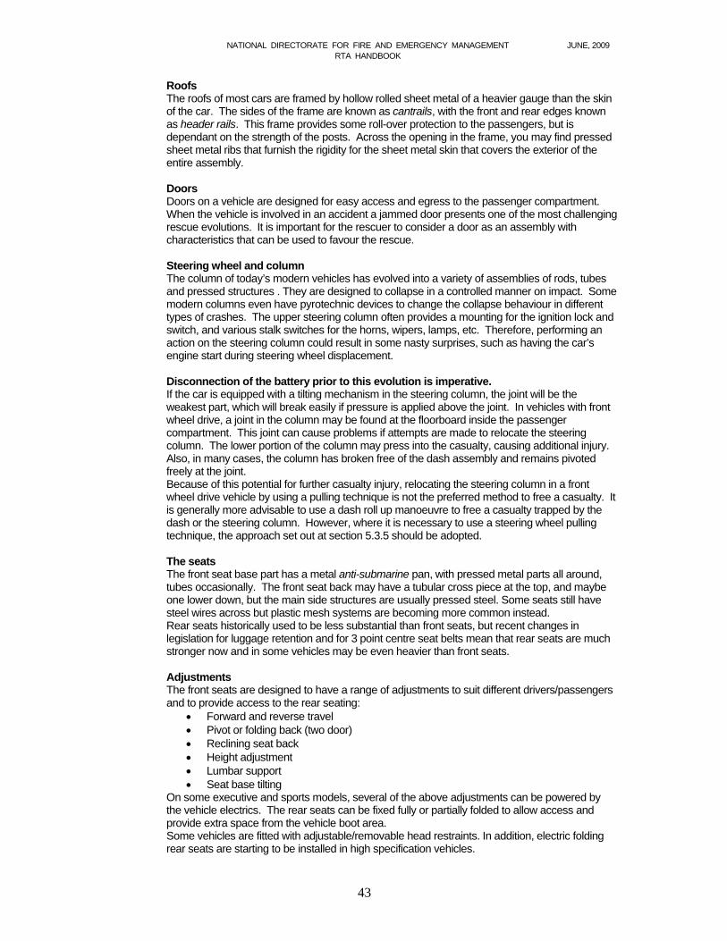
NATIONAL DIRECTORATE FOR FIRE AND EMERGENCY MANAGEMENT JUNE, 2009 RTA HANDBOOK
43
Roofs The roofs of most cars are framed by hollow rolled sheet metal of a heavier gauge than the skin of the car. The sides of the frame are known as cantrails, with the front and rear edges known as header rails. This frame provides some roll-over protection to the passengers, but is dependant on the strength of the posts. Across the opening in the frame, you may find pressed sheet metal ribs that furnish the rigidity for the sheet metal skin that covers the exterior of the entire assembly. Doors Doors on a vehicle are designed for easy access and egress to the passenger compartment. When the vehicle is involved in an accident a jammed door presents one of the most challenging rescue evolutions. It is important for the rescuer to consider a door as an assembly with characteristics that can be used to favour the rescue. Steering wheel and column The column of today’s modern vehicles has evolved into a variety of assemblies of rods, tubes and pressed structures . They are designed to collapse in a controlled manner on impact. Some modern columns even have pyrotechnic devices to change the collapse behaviour in different types of crashes. The upper steering column often provides a mounting for the ignition lock and switch, and various stalk switches for the horns, wipers, lamps, etc. Therefore, performing an action on the steering column could result in some nasty surprises, such as having the car’s engine start during steering wheel displacement. Disconnection of the battery prior to this evolution is imperative. If the car is equipped with a tilting mechanism in the steering column, the joint will be the weakest part, which will break easily if pressure is applied above the joint. In vehicles with front wheel drive, a joint in the column may be found at the floorboard inside the passenger compartment. This joint can cause problems if attempts are made to relocate the steering column. The lower portion of the column may press into the casualty, causing additional injury. Also, in many cases, the column has broken free of the dash assembly and remains pivoted freely at the joint. Because of this potential for further casualty injury, relocating the steering column in a front wheel drive vehicle by using a pulling technique is not the preferred method to free a casualty. It is generally more advisable to use a dash roll up manoeuvre to free a casualty trapped by the dash or the steering column. However, where it is necessary to use a steering wheel pulling technique, the approach set out at section 5.3.5 should be adopted. The seats The front seat base part has a metal anti-submarine pan, with pressed metal parts all around, tubes occasionally. The front seat back may have a tubular cross piece at the top, and maybe one lower down, but the main side structures are usually pressed steel. Some seats still have steel wires across but plastic mesh systems are becoming more common instead. Rear seats historically used to be less substantial than front seats, but recent changes in legislation for luggage retention and for 3 point centre seat belts mean that rear seats are much stronger now and in some vehicles may be even heavier than front seats. Adjustments The front seats are designed to have a range of adjustments to suit different drivers/passengers and to provide access to the rear seating:
Forward and reverse travel Pivot or folding back (two door) Reclining seat back Height adjustment Lumbar support Seat base tilting
On some executive and sports models, several of the above adjustments can be powered by the vehicle electrics. The rear seats can be fixed fully or partially folded to allow access and provide extra space from the vehicle boot area. Some vehicles are fitted with adjustable/removable head restraints. In addition, electric folding rear seats are starting to be installed in high specification vehicles.
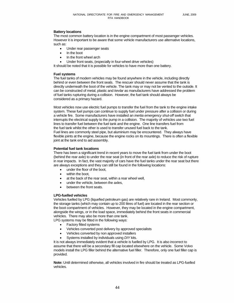
NATIONAL DIRECTORATE FOR FIRE AND EMERGENCY MANAGEMENT JUNE, 2009 RTA HANDBOOK
44
Battery locations The most common battery location is in the engine compartment of most passenger vehicles. However it is important to be aware that some vehicle manufacturers use alternative locations, such as:
Under rear passenger seats In the boot In the front wheel arch Under front seats, (especially in four-wheel drive vehicles)
It should be noted that it is possible for vehicles to have more than one battery. Fuel systems The fuel tanks of modern vehicles may be found anywhere in the vehicle, including directly behind or even between the front seats. The rescuer should never assume that the tank is directly underneath the boot of the vehicle. The tank may or may not be vented to the outside. It can be constructed of metal, plastic and kevlar as manufacturers have addressed the problem of fuel tanks rupturing during a collision. However, the fuel tank should always be considered as a primary hazard. Most vehicles now use electric fuel pumps to transfer the fuel from the tank to the engine intake system. These fuel pumps can continue to supply fuel under pressure after a collision or during a vehicle fire. Some manufacturers have installed an inertia emergency shut-off switch that interrupts the electrical supply to the pump in a collision. The majority of vehicles use two fuel lines to transfer fuel between the fuel tank and the engine. One line transfers fuel from the fuel tank whilst the other is used to transfer unused fuel back to the tank. Fuel lines are commonly steel pipe, but aluminium may be encountered. They always have flexible joints at the engine, because the engine rocks on its mountings. There is often a flexible joint at the tank end to aid assembly. Potential fuel tank locations There has been a significant trend in recent years to move the fuel tank from under the boot (behind the rear axle) to under the rear seat (in front of the rear axle) to reduce the risk of rupture in rear impacts. In fact, the vast majority of cars have the fuel tanks under the rear seat but there are always exceptions and they can still be found in the following locations:
under the floor of the boot, within the boot, at the back of the rear seat, within a rear wheel well, under the vehicle, between the axles, between the front seats.
LPG-fuelled vehicles Vehicles fuelled by LPG (liquefied petroleum gas) are relatively rare in Ireland. Most commonly, the storage tanks (which may contain up to 200 litres of fuel) are located in the rear section or the boot compartment of vehicles. However, they may be located in the engine compartment, alongside the wings, or in the load space, immediately behind the front seats in commercial vehicles. There may also be more than one tank. LPG systems may be fitted in the following ways:
Factory fitted systems Vehicles converted post delivery by approved specialists Vehicles converted by non approved installers Systems installed by individuals using DIY kits.
It is not always immediately evident that a vehicle is fuelled by LPG. It is also incorrect to assume that there will be a secondary fill cap located elsewhere on the vehicle. Some Volvo models install the LPG filler behind the alternative fuel filler. Therefore, only one fuel filler cap is provided. Note: Until determined otherwise, all vehicles involved in fire should be treated as LPG-fuelled vehicles.
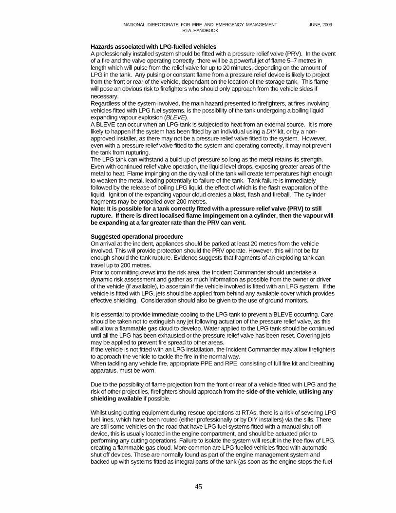
NATIONAL DIRECTORATE FOR FIRE AND EMERGENCY MANAGEMENT JUNE, 2009 RTA HANDBOOK
45
Hazards associated with LPG-fuelled vehicles A professionally installed system should be fitted with a pressure relief valve (PRV). In the event of a fire and the valve operating correctly, there will be a powerful jet of flame 5–7 metres in length which will pulse from the relief valve for up to 20 minutes, depending on the amount of LPG in the tank. Any pulsing or constant flame from a pressure relief device is likely to project from the front or rear of the vehicle, dependant on the location of the storage tank. This flame will pose an obvious risk to firefighters who should only approach from the vehicle sides if necessary. Regardless of the system involved, the main hazard presented to firefighters, at fires involving vehicles fitted with LPG fuel systems, is the possibility of the tank undergoing a boiling liquid expanding vapour explosion (BLEVE). A BLEVE can occur when an LPG tank is subjected to heat from an external source. It is more likely to happen if the system has been fitted by an individual using a DIY kit, or by a non-approved installer, as there may not be a pressure relief valve fitted to the system. However, even with a pressure relief valve fitted to the system and operating correctly, it may not prevent the tank from rupturing. The LPG tank can withstand a build up of pressure so long as the metal retains its strength. Even with continued relief valve operation, the liquid level drops, exposing greater areas of the metal to heat. Flame impinging on the dry wall of the tank will create temperatures high enough to weaken the metal, leading potentially to failure of the tank. Tank failure is immediately followed by the release of boiling LPG liquid, the effect of which is the flash evaporation of the liquid. Ignition of the expanding vapour cloud creates a blast, flash and fireball. The cylinder fragments may be propelled over 200 metres. Note: It is possible for a tank correctly fitted with a pressure relief valve (PRV) to still rupture. If there is direct localised flame impingement on a cylinder, then the vapour will be expanding at a far greater rate than the PRV can vent. Suggested operational procedure On arrival at the incident, appliances should be parked at least 20 metres from the vehicle involved. This will provide protection should the PRV operate. However, this will not be far enough should the tank rupture. Evidence suggests that fragments of an exploding tank can travel up to 200 metres. Prior to committing crews into the risk area, the Incident Commander should undertake a dynamic risk assessment and gather as much information as possible from the owner or driver of the vehicle (if available), to ascertain if the vehicle involved is fitted with an LPG system. If the vehicle is fitted with LPG, jets should be applied from behind any available cover which provides effective shielding. Consideration should also be given to the use of ground monitors.
It is essential to provide immediate cooling to the LPG tank to prevent a BLEVE occurring. Care should be taken not to extinguish any jet following actuation of the pressure relief valve, as this will allow a flammable gas cloud to develop. Water applied to the LPG tank should be continued until all the LPG has been exhausted or the pressure relief valve has been reset. Covering jets may be applied to prevent fire spread to other areas. If the vehicle is not fitted with an LPG installation, the Incident Commander may allow firefighters to approach the vehicle to tackle the fire in the normal way. When tackling any vehicle fire, appropriate PPE and RPE, consisting of full fire kit and breathing apparatus, must be worn.
Due to the possibility of flame projection from the front or rear of a vehicle fitted with LPG and the risk of other projectiles, firefighters should approach from the side of the vehicle, utilising any shielding available if possible. Whilst using cutting equipment during rescue operations at RTAs, there is a risk of severing LPG fuel lines, which have been routed (either professionally or by DIY installers) via the sills. There are still some vehicles on the road that have LPG fuel systems fitted with a manual shut off device, this is usually located in the engine compartment, and should be actuated prior to performing any cutting operations. Failure to isolate the system will result in the free flow of LPG, creating a flammable gas cloud. More common are LPG fuelled vehicles fitted with automatic shut off devices. These are normally found as part of the engine management system and backed up with systems fitted as integral parts of the tank (as soon as the engine stops the fuel
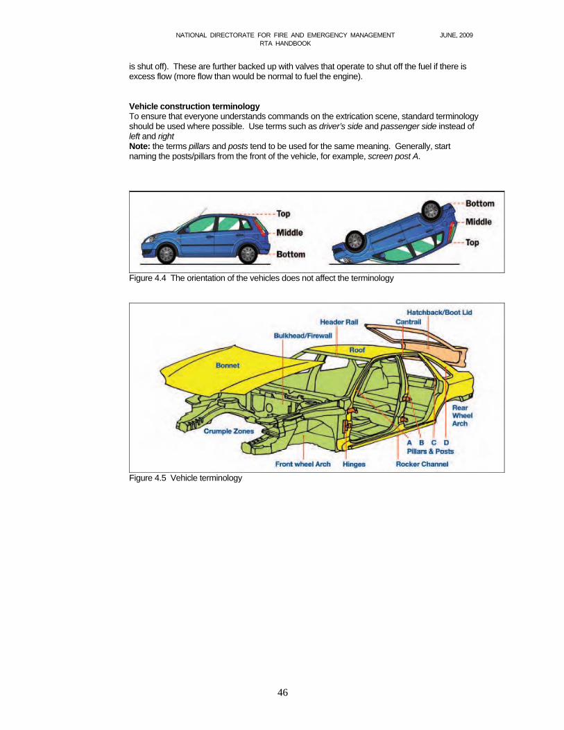
NATIONAL DIRECTORATE FOR FIRE AND EMERGENCY MANAGEMENT JUNE, 2009 RTA HANDBOOK
46
is shut off). These are further backed up with valves that operate to shut off the fuel if there is excess flow (more flow than would be normal to fuel the engine). Vehicle construction terminology To ensure that everyone understands commands on the extrication scene, standard terminology should be used where possible. Use terms such as driver’s side and passenger side instead of left and right Note: the terms pillars and posts tend to be used for the same meaning. Generally, start naming the posts/pillars from the front of the vehicle, for example, screen post A.
Figure 4.4 The orientation of the vehicles does not affect the terminology
Figure 4.5 Vehicle terminology
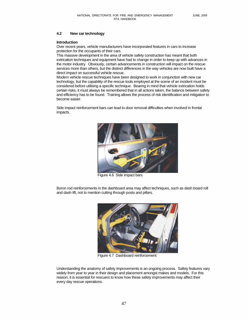
NATIONAL DIRECTORATE FOR FIRE AND EMERGENCY MANAGEMENT JUNE, 2009 RTA HANDBOOK
47
4.2 New car technology Introduction Over recent years, vehicle manufacturers have incorporated features in cars to increase protection for the occupants of their cars. This massive development in the area of vehicle safety construction has meant that both extrication techniques and equipment have had to change in order to keep up with advances in the motor industry. Obviously, certain advancements in construction will impact on the rescue services more than others, but the distinct differences in the way vehicles are now built have a direct impact on successful vehicle rescue. Modern vehicle rescue techniques have been designed to work in conjunction with new car technology, but the capability of the rescue tools employed at the scene of an incident must be considered before utilising a specific technique. Bearing in mind that vehicle extrication holds certain risks, it must always be remembered that in all actions taken, the balance between safety and efficiency has to be found. Training allows the process of risk identification and mitigation to become easier. Side impact reinforcement bars can lead to door removal difficulties when involved in frontal impacts.
Figure 4.6 Side impact bars Boron rod reinforcements in the dashboard area may affect techniques, such as dash board roll and dash lift, not to mention cutting through posts and pillars.
Figure 4.7 Dashboard reinforcement Understanding the anatomy of safety improvements is an ongoing process. Safety features vary widely from year to year in their design and placement amongst makes and models. For this reason, it is essential for rescuers to know how these safety improvements may affect their every day rescue operations.
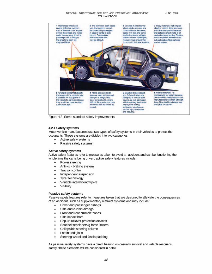
NATIONAL DIRECTORATE FOR FIRE AND EMERGENCY MANAGEMENT JUNE, 2009 RTA HANDBOOK
48
Figure 4.8 Some standard safety improvements
4.2.1 Safety systems Motor vehicle manufacturers use two types of safety systems in their vehicles to protect the occupants. These systems are divided into two categories:
Active safety systems Passive safety systems
Active safety systems Active safety features refer to measures taken to avoid an accident and can be functioning the whole time the car is being driven, active safety features include:
Power steering Anti-lock braking system Traction control Independent suspension Tyre Technology Variable intermittent wipers Visibility.
Passive safety systems Passive safety features refer to measures taken that are designed to alleviate the consequences of an accident, such as supplementary restraint systems and may include:
Driver and passenger airbags Side and curtain airbags Front and rear crumple zones Side impact bars Pop-up rollover protection devices Seat belt tensioners/g-force limiters Collapsible steering column Laminated glass Steering wheel and fascia padding
As passive safety systems have a direct bearing on casualty survival and vehicle rescuer's safety, these elements will be considered in detail.
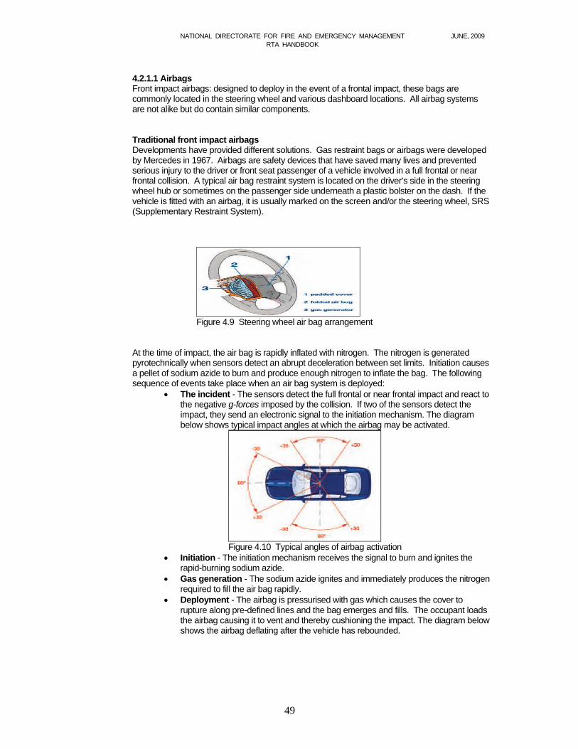
NATIONAL DIRECTORATE FOR FIRE AND EMERGENCY MANAGEMENT JUNE, 2009 RTA HANDBOOK
49
4.2.1.1 Airbags Front impact airbags: designed to deploy in the event of a frontal impact, these bags are commonly located in the steering wheel and various dashboard locations. All airbag systems are not alike but do contain similar components. Traditional front impact airbags Developments have provided different solutions. Gas restraint bags or airbags were developed by Mercedes in 1967. Airbags are safety devices that have saved many lives and prevented serious injury to the driver or front seat passenger of a vehicle involved in a full frontal or near frontal collision. A typical air bag restraint system is located on the driver’s side in the steering wheel hub or sometimes on the passenger side underneath a plastic bolster on the dash. If the vehicle is fitted with an airbag, it is usually marked on the screen and/or the steering wheel, SRS (Supplementary Restraint System).
Figure 4.9 Steering wheel air bag arrangement
At the time of impact, the air bag is rapidly inflated with nitrogen. The nitrogen is generated pyrotechnically when sensors detect an abrupt deceleration between set limits. Initiation causes a pellet of sodium azide to burn and produce enough nitrogen to inflate the bag. The following sequence of events take place when an air bag system is deployed:
The incident - The sensors detect the full frontal or near frontal impact and react to the negative g-forces imposed by the collision. If two of the sensors detect the impact, they send an electronic signal to the initiation mechanism. The diagram below shows typical impact angles at which the airbag may be activated.
Figure 4.10 Typical angles of airbag activation
Initiation - The initiation mechanism receives the signal to burn and ignites the rapid-burning sodium azide.
Gas generation - The sodium azide ignites and immediately produces the nitrogen required to fill the air bag rapidly.
Deployment - The airbag is pressurised with gas which causes the cover to rupture along pre-defined lines and the bag emerges and fills. The occupant loads the airbag causing it to vent and thereby cushioning the impact. The diagram below shows the airbag deflating after the vehicle has rebounded.
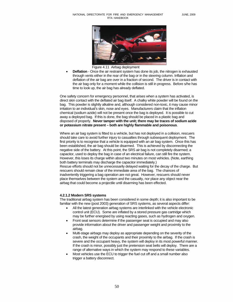
NATIONAL DIRECTORATE FOR FIRE AND EMERGENCY MANAGEMENT JUNE, 2009 RTA HANDBOOK
50
Figure 4.11 Airbag deployment
Deflation - Once the air restraint system has done its job, the nitrogen is exhausted through vents either in the rear of the bag or in the steering column. Inflation and deflation of the air bag are over in a fraction of second. The driver is in contact with the air bag only for a moment while the collision is still in progress. Before s/he has time to look up, the air bag has already deflated.
One safety concern for emergency personnel, that arises when a system has activated, is direct skin contact with the deflated air bag itself. A chalky white powder will be found on the bag. This powder is slightly alkaline and, although considered non-toxic, it may cause minor irritation to an individual’s skin, nose and eyes. Manufacturers claim that the inflation chemical (sodium azide) will not be present once the bag is deployed. It is possible to cut away a deployed bag. If this is done, the bag should be placed in a plastic bag and disposed of properly. Never tamper with the unit; there may be traces of sodium azide or potassium nitrate present – both are highly flammable and poisonous. Where an air bag system is fitted to a vehicle, but has not deployed in a collision, rescuers should take care to avoid further injury to casualties through subsequent deployment. The first priority is to recognise that a vehicle is equipped with an air bag system. Once this has been established, the air bag should be disarmed. This is achieved by disconnecting the negative side of the battery. At this point, the SRS air bag is not completely disarmed; a capacitor, used to deploy the bag in case of an electrical failure, can still fire the system. However, this loses its charge within about two minutes on most vehicles. (Note, earthing both battery terminals may discharge the capacitor immediately.) Rescue efforts should not be unnecessarily delayed waiting for the decay of the charge. But rescuers should remain clear of the immediate area of the bag. The chances of inadvertently triggering a bag operation are not great. However, rescuers should never place themselves between the system and the casualty, nor place any object near the airbag that could become a projectile until disarming has been effected. 4.2.1.2 Modern SRS systems The traditional airbag system has been considered in some depth; it is also important to be familiar with the new (post 2003) generation of SRS systems, as several aspects differ:
All the latest generation airbag systems are interlinked with the vehicle electronic control unit (ECU). Some are inflated by a stored pressure gas cartridge which may be further energised by using reacting gases, such as hydrogen and oxygen.
Front seat sensors determine if the passenger seat is occupied and may also provide information about the driver and passenger weight and proximity to the airbag.
Multi-stage airbags may deploy as appropriate depending on the severity of the crash, the weight of the occupants and their proximity to the airbag. If the crash is severe and the occupant heavy, the system will deploy in its most powerful manner. If the crash is minor, possibly just the pretension seat belts will deploy. There are a range of alternative ways in which the system may respond to these variables.
Most vehicles use the ECU to trigger the fuel cut off and a small number also trigger a battery disconnect.
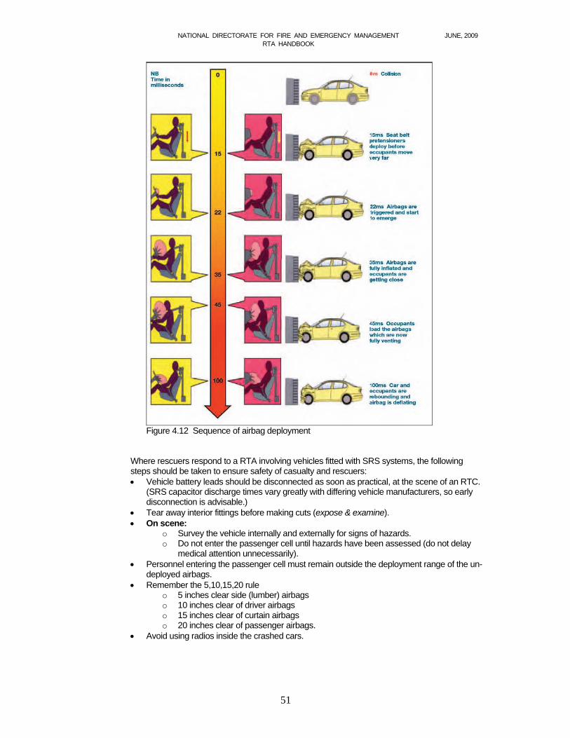
NATIONAL DIRECTORATE FOR FIRE AND EMERGENCY MANAGEMENT JUNE, 2009 RTA HANDBOOK
51
Figure 4.12 Sequence of airbag deployment
Where rescuers respond to a RTA involving vehicles fitted with SRS systems, the following steps should be taken to ensure safety of casualty and rescuers: Vehicle battery leads should be disconnected as soon as practical, at the scene of an RTC.
(SRS capacitor discharge times vary greatly with differing vehicle manufacturers, so early disconnection is advisable.)
Tear away interior fittings before making cuts (expose & examine). On scene:
o Survey the vehicle internally and externally for signs of hazards. o Do not enter the passenger cell until hazards have been assessed (do not delay
medical attention unnecessarily). Personnel entering the passenger cell must remain outside the deployment range of the un-
deployed airbags. Remember the 5,10,15,20 rule
o 5 inches clear side (lumber) airbags o 10 inches clear of driver airbags o 15 inches clear of curtain airbags o 20 inches clear of passenger airbags.
Avoid using radios inside the crashed cars.
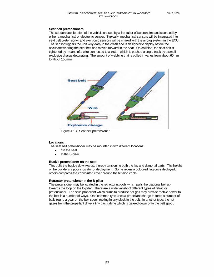
NATIONAL DIRECTORATE FOR FIRE AND EMERGENCY MANAGEMENT JUNE, 2009 RTA HANDBOOK
52
Seat belt pretensioners The sudden deceleration of the vehicle caused by a frontal or offset front impact is sensed by either a mechanical or electronic sensor. Typically, mechanical sensors will be integrated into seat belt pretensioner and electronic sensors will be shared with the airbag system in the ECU. The sensor triggers the unit very early in the crash and is designed to deploy before the occupant wearing the seat belt has moved forward in the seat. On collision, the seat belt is tightened by means of a wire connected to a piston which is pushed along a track by a small explosive charge detonating. The amount of webbing that is pulled in varies from about 60mm to about 150mm.
Figure 4.13 Seat belt pretensioner Locations The seat belt pretensioner may be mounted in two different locations:
On the seat In the B-pillar.
Buckle pretensioner on the seat This pulls the buckle downwards, thereby tensioning both the lap and diagonal parts. The height of the buckle is a poor indicator of deployment. Some reveal a coloured flag once deployed, others compress the convoluted cover around the tension cable. Retractor pretensioner in the B-pillar The pretensioner may be located in the retractor (spool), which pulls the diagonal belt up towards the loop on the B-pillar. There are a wide variety of different types of retractor pretensioner. The solid propellant which burns to produce hot gas may provide motive power to the belt in a number of ways. One common type uses a propellant charge to force a number of balls round a gear on the belt spool, reeling in any slack in the belt. In another type, the hot gases from the propellant drive a tiny gas turbine which is geared down onto the belt spool.
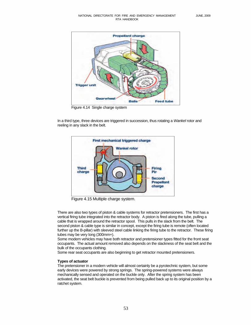
NATIONAL DIRECTORATE FOR FIRE AND EMERGENCY MANAGEMENT JUNE, 2009 RTA HANDBOOK
53
Figure 4.14 Single charge system
In a third type, three devices are triggered in succession, thus rotating a Wankel rotor and reeling in any slack in the belt.
Figure 4.15 Multiple charge system.
There are also two types of piston & cable systems for retractor pretensioners. The first has a vertical firing tube integrated into the retractor body. A piston is fired along the tube, pulling a cable that is wrapped around the retractor spool. This pulls in the slack from the belt. The second piston & cable type is similar in concept, except the firing tube is remote (often located further up the B-pillar) with sleeved steel cable linking the firing tube to the retractor. These firing tubes may be very long (300mm+). Some modern vehicles may have both retractor and pretensioner types fitted for the front seat occupants. The actual amount removed also depends on the slackness of the seat belt and the bulk of the occupants clothing. Some rear seat occupants are also beginning to get retractor mounted pretensioners.
Types of actuator The pretensioner in a modern vehicle will almost certainly be a pyrotechnic system, but some early devices were powered by strong springs. The spring-powered systems were always mechanically sensed and operated on the buckle only. After the spring system has been activated, the seat belt buckle is prevented from being pulled back up to its original position by a ratchet system.
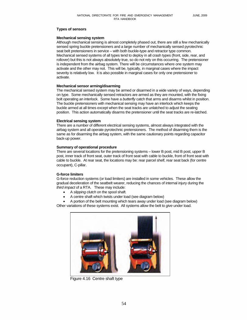
NATIONAL DIRECTORATE FOR FIRE AND EMERGENCY MANAGEMENT JUNE, 2009 RTA HANDBOOK
54
Types of sensors Mechanical sensing system Although mechanical sensing is almost completely phased out, there are still a few mechanically sensed spring buckle pretensioners and a large number of mechanically sensed pyrotechnic seat belt pretensioners in service – with both buckle-type and retractor type common. Mechanical sensed systems of all types tend to deploy in all crash types (front, side, rear, and rollover) but this is not always absolutely true, so do not rely on this occurring. The pretensioner is independent from the airbag system. There will be circumstances where one system may activate and the other may not. This will be, typically, in marginal cases where the impact severity is relatively low. It is also possible in marginal cases for only one pretensioner to activate. Mechanical sensor arming/disarming The mechanical sensed system may be armed or disarmed in a wide variety of ways, depending on type. Some mechanically sensed retractors are armed as they are mounted, with the fixing bolt operating an interlock. Some have a butterfly catch that arms and disarms whilst in position. The buckle pretensioners with mechanical sensing may have an interlock which keeps the buckle armed at all times except when the seat tracks are unlatched to adjust the seating position. This action automatically disarms the pretensioner until the seat tracks are re-latched. Electrical sensing system There are a number of different electrical sensing systems, almost always integrated with the airbag system and all operate pyrotechnic pretensioners. The method of disarming them is the same as for disarming the airbag system, with the same cautionary points regarding capacitor back-up power. Summary of operational procedure There are several locations for the pretensioning systems – lower B post, mid B post, upper B post, inner track of front seat, outer track of front seat with cable to buckle, front of front seat with cable to buckle. At rear seat, the locations may be: rear parcel shelf, rear seat back (for centre occupant), C-pillar. G-force limiters G-force reduction systems (or load limiters) are installed in some vehicles. These allow the gradual deceleration of the seatbelt wearer, reducing the chances of internal injury during the third impact of a RTA. These may include:
A slipping clutch on the spool shaft. A centre shaft which twists under load (see diagram below) A portion of the belt mounting which tears away under load (see diagram below)
Other variations of these systems exist. All systems allow the belt to give under load.
Figure 4.16 Centre shaft type
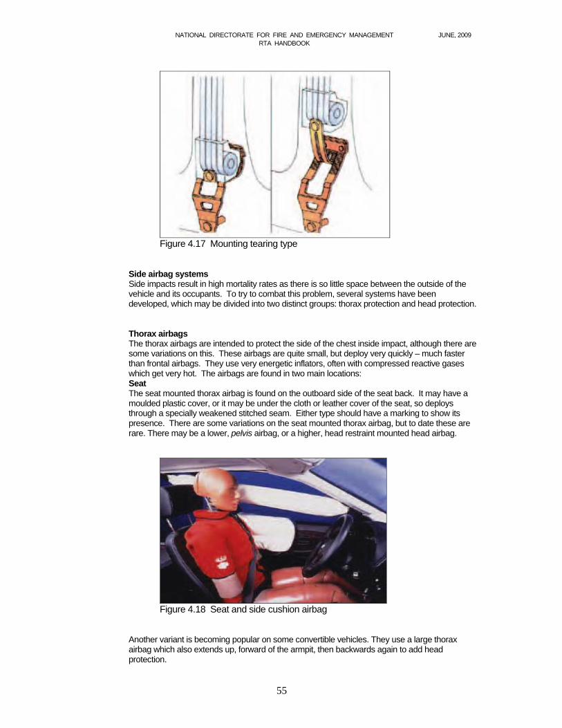
NATIONAL DIRECTORATE FOR FIRE AND EMERGENCY MANAGEMENT JUNE, 2009 RTA HANDBOOK
55
Figure 4.17 Mounting tearing type
Side airbag systems Side impacts result in high mortality rates as there is so little space between the outside of the vehicle and its occupants. To try to combat this problem, several systems have been developed, which may be divided into two distinct groups: thorax protection and head protection. Thorax airbags The thorax airbags are intended to protect the side of the chest inside impact, although there are some variations on this. These airbags are quite small, but deploy very quickly – much faster than frontal airbags. They use very energetic inflators, often with compressed reactive gases which get very hot. The airbags are found in two main locations: Seat The seat mounted thorax airbag is found on the outboard side of the seat back. It may have a moulded plastic cover, or it may be under the cloth or leather cover of the seat, so deploys through a specially weakened stitched seam. Either type should have a marking to show its presence. There are some variations on the seat mounted thorax airbag, but to date these are rare. There may be a lower, pelvis airbag, or a higher, head restraint mounted head airbag.
Figure 4.18 Seat and side cushion airbag
Another variant is becoming popular on some convertible vehicles. They use a large thorax airbag which also extends up, forward of the armpit, then backwards again to add head protection.
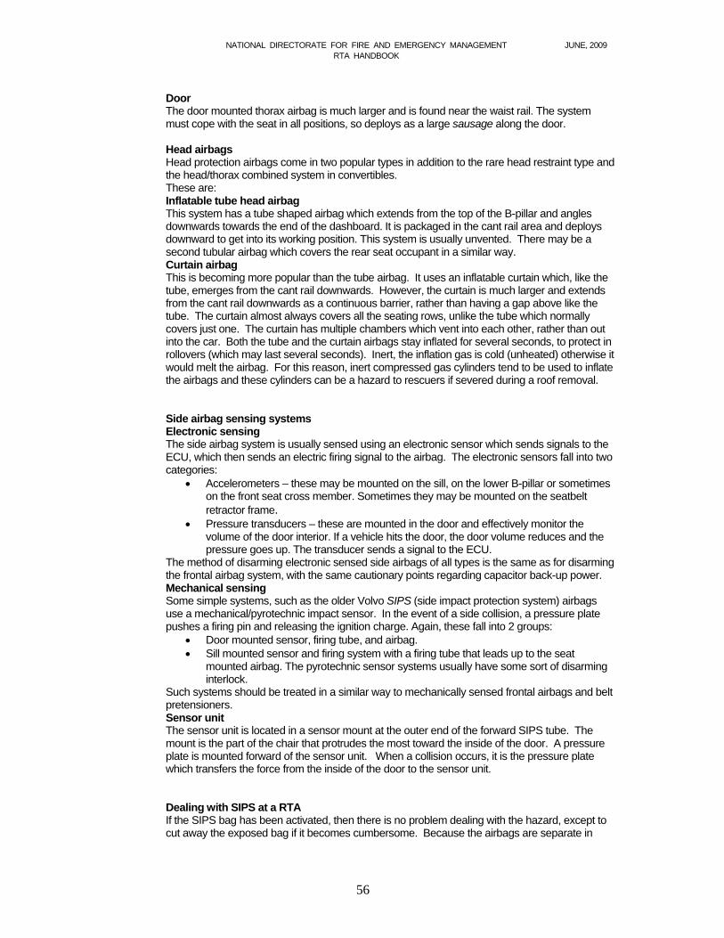
NATIONAL DIRECTORATE FOR FIRE AND EMERGENCY MANAGEMENT JUNE, 2009 RTA HANDBOOK
56
Door The door mounted thorax airbag is much larger and is found near the waist rail. The system must cope with the seat in all positions, so deploys as a large sausage along the door.
Head airbags Head protection airbags come in two popular types in addition to the rare head restraint type and the head/thorax combined system in convertibles. These are: Inflatable tube head airbag This system has a tube shaped airbag which extends from the top of the B-pillar and angles downwards towards the end of the dashboard. It is packaged in the cant rail area and deploys downward to get into its working position. This system is usually unvented. There may be a second tubular airbag which covers the rear seat occupant in a similar way. Curtain airbag This is becoming more popular than the tube airbag. It uses an inflatable curtain which, like the tube, emerges from the cant rail downwards. However, the curtain is much larger and extends from the cant rail downwards as a continuous barrier, rather than having a gap above like the tube. The curtain almost always covers all the seating rows, unlike the tube which normally covers just one. The curtain has multiple chambers which vent into each other, rather than out into the car. Both the tube and the curtain airbags stay inflated for several seconds, to protect in rollovers (which may last several seconds). Inert, the inflation gas is cold (unheated) otherwise it would melt the airbag. For this reason, inert compressed gas cylinders tend to be used to inflate the airbags and these cylinders can be a hazard to rescuers if severed during a roof removal. Side airbag sensing systems Electronic sensing The side airbag system is usually sensed using an electronic sensor which sends signals to the ECU, which then sends an electric firing signal to the airbag. The electronic sensors fall into two categories:
Accelerometers – these may be mounted on the sill, on the lower B-pillar or sometimes on the front seat cross member. Sometimes they may be mounted on the seatbelt retractor frame.
Pressure transducers – these are mounted in the door and effectively monitor the volume of the door interior. If a vehicle hits the door, the door volume reduces and the pressure goes up. The transducer sends a signal to the ECU.
The method of disarming electronic sensed side airbags of all types is the same as for disarming the frontal airbag system, with the same cautionary points regarding capacitor back-up power. Mechanical sensing Some simple systems, such as the older Volvo SIPS (side impact protection system) airbags use a mechanical/pyrotechnic impact sensor. In the event of a side collision, a pressure plate pushes a firing pin and releasing the ignition charge. Again, these fall into 2 groups:
Door mounted sensor, firing tube, and airbag. Sill mounted sensor and firing system with a firing tube that leads up to the seat
mounted airbag. The pyrotechnic sensor systems usually have some sort of disarming interlock.
Such systems should be treated in a similar way to mechanically sensed frontal airbags and belt pretensioners. Sensor unit The sensor unit is located in a sensor mount at the outer end of the forward SIPS tube. The mount is the part of the chair that protrudes the most toward the inside of the door. A pressure plate is mounted forward of the sensor unit. When a collision occurs, it is the pressure plate which transfers the force from the inside of the door to the sensor unit. Dealing with SIPS at a RTA If the SIPS bag has been activated, then there is no problem dealing with the hazard, except to cut away the exposed bag if it becomes cumbersome. Because the airbags are separate in
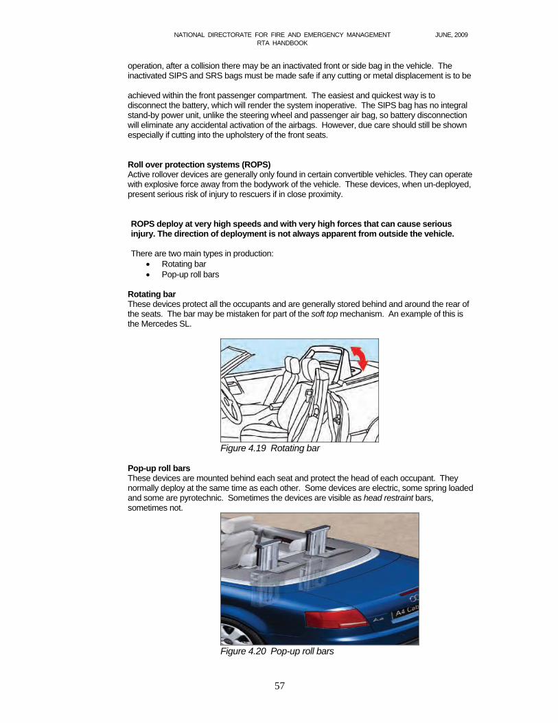
NATIONAL DIRECTORATE FOR FIRE AND EMERGENCY MANAGEMENT JUNE, 2009 RTA HANDBOOK
57
operation, after a collision there may be an inactivated front or side bag in the vehicle. The inactivated SIPS and SRS bags must be made safe if any cutting or metal displacement is to be achieved within the front passenger compartment. The easiest and quickest way is to disconnect the battery, which will render the system inoperative. The SIPS bag has no integral stand-by power unit, unlike the steering wheel and passenger air bag, so battery disconnection will eliminate any accidental activation of the airbags. However, due care should still be shown especially if cutting into the upholstery of the front seats. Roll over protection systems (ROPS) Active rollover devices are generally only found in certain convertible vehicles. They can operate with explosive force away from the bodywork of the vehicle. These devices, when un-deployed, present serious risk of injury to rescuers if in close proximity. ROPS deploy at very high speeds and with very high forces that can cause serious injury. The direction of deployment is not always apparent from outside the vehicle.
There are two main types in production:
Rotating bar Pop-up roll bars
Rotating bar These devices protect all the occupants and are generally stored behind and around the rear of the seats. The bar may be mistaken for part of the soft top mechanism. An example of this is the Mercedes SL.
Figure 4.19 Rotating bar
Pop-up roll bars These devices are mounted behind each seat and protect the head of each occupant. They normally deploy at the same time as each other. Some devices are electric, some spring loaded and some are pyrotechnic. Sometimes the devices are visible as head restraint bars, sometimes not.
Figure 4.20 Pop-up roll bars
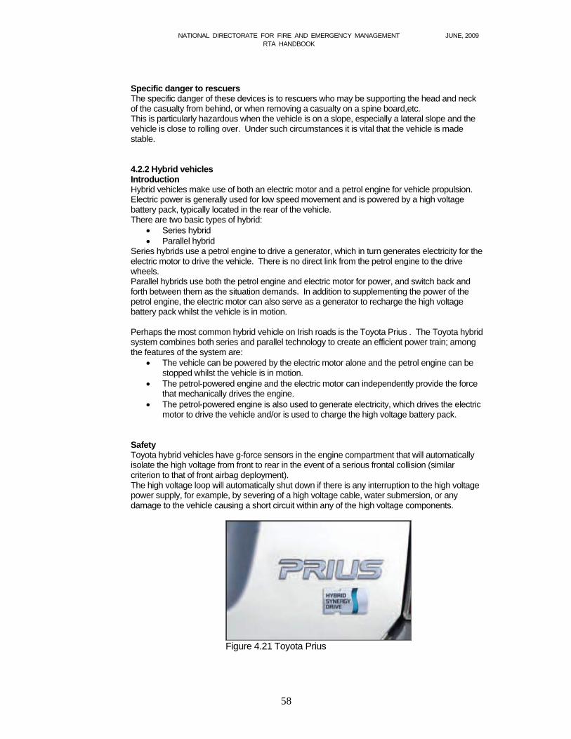
NATIONAL DIRECTORATE FOR FIRE AND EMERGENCY MANAGEMENT JUNE, 2009 RTA HANDBOOK
58
Specific danger to rescuers The specific danger of these devices is to rescuers who may be supporting the head and neck of the casualty from behind, or when removing a casualty on a spine board,etc. This is particularly hazardous when the vehicle is on a slope, especially a lateral slope and the vehicle is close to rolling over. Under such circumstances it is vital that the vehicle is made stable. 4.2.2 Hybrid vehicles Introduction Hybrid vehicles make use of both an electric motor and a petrol engine for vehicle propulsion. Electric power is generally used for low speed movement and is powered by a high voltage battery pack, typically located in the rear of the vehicle. There are two basic types of hybrid:
Series hybrid Parallel hybrid
Series hybrids use a petrol engine to drive a generator, which in turn generates electricity for the electric motor to drive the vehicle. There is no direct link from the petrol engine to the drive wheels. Parallel hybrids use both the petrol engine and electric motor for power, and switch back and forth between them as the situation demands. In addition to supplementing the power of the petrol engine, the electric motor can also serve as a generator to recharge the high voltage battery pack whilst the vehicle is in motion. Perhaps the most common hybrid vehicle on Irish roads is the Toyota Prius . The Toyota hybrid system combines both series and parallel technology to create an efficient power train; among the features of the system are:
The vehicle can be powered by the electric motor alone and the petrol engine can be stopped whilst the vehicle is in motion.
The petrol-powered engine and the electric motor can independently provide the force that mechanically drives the engine.
The petrol-powered engine is also used to generate electricity, which drives the electric motor to drive the vehicle and/or is used to charge the high voltage battery pack.
Safety Toyota hybrid vehicles have g-force sensors in the engine compartment that will automatically isolate the high voltage from front to rear in the event of a serious frontal collision (similar criterion to that of front airbag deployment). The high voltage loop will automatically shut down if there is any interruption to the high voltage power supply, for example, by severing of a high voltage cable, water submersion, or any damage to the vehicle causing a short circuit within any of the high voltage components.
Figure 4.21 Toyota Prius

NATIONAL DIRECTORATE FOR FIRE AND EMERGENCY MANAGEMENT JUNE, 2009 RTA HANDBOOK
59
In hybrid vehicles, high voltage cables are identifiable by orange insulation and connectors. Whilst there is a need to be aware of these cables, they are routed underneath and inside the floor plan reinforcement, in an area that is not generally accessed by rescue personnel. It is also important to note that hybrid vehicles, that may appear inactive when the petrol engine is not running, may still be in the ready state and capable of motion at any time. Always ensure that the main ignition switch is turned off, therefore disabling the electronic drive system. Except for the precautions listed in this section, hybrid vehicles may be approached using standard vehicle extrication principles and techniques. Additional information can be obtained from rescuers guides published by the various vehicle manufacturers.
4.2.3 Vehicle electrics Introduction Managing vehicle electrical systems is an important task at the scene of a road traffic collision. A full survey of the vehicle, including central locking systems, electric windows, power seats, SRS systems and power boot/ bonnet release mechanisms should be undertaken before battery disconnection is finalised. In order for firefighters to deal with vehicle electrical systems safely, a basic knowledge of components and materials is required.
Figure 4.22 Always consider disconnection of the high voltage system to afford optimum safety to rescuers and casualties .
Vehicle electrical systems A typical vehicle electrical system has an alternator to generate electrical power and large amounts of cabling (sometimes in the form of a thick wiring loom) to distribute the power. Electrical switches and connectors complete the electrical circuit. At least one battery stores energy to start the vehicle and power electrical equipment as required. Vehicle batteries Car batteries are generally rated as 12 volts, with two terminals, one positive and one negative. Connected to one of the terminals will be an earthing wire, with the vehicle either positively or negatively earthed. This is the terminal that should be disconnected first, as it reduces the chance of sparking. Multiple batteries Many modern vehicles have more than one battery. Obviously, the most common location is in the engine compartment. It is important to be aware of newer vehicle designs that make use of alternative locations, these locations may include, but are not limited to:
Under the rear passenger seat In the boot In the front wheel arch.
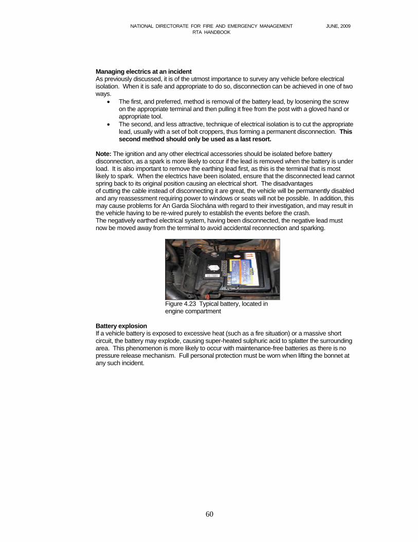
NATIONAL DIRECTORATE FOR FIRE AND EMERGENCY MANAGEMENT JUNE, 2009 RTA HANDBOOK
60
Managing electrics at an incident As previously discussed, it is of the utmost importance to survey any vehicle before electrical isolation. When it is safe and appropriate to do so, disconnection can be achieved in one of two ways.
The first, and preferred, method is removal of the battery lead, by loosening the screw on the appropriate terminal and then pulling it free from the post with a gloved hand or appropriate tool.
The second, and less attractive, technique of electrical isolation is to cut the appropriate lead, usually with a set of bolt croppers, thus forming a permanent disconnection. This second method should only be used as a last resort.
Note: The ignition and any other electrical accessories should be isolated before battery disconnection, as a spark is more likely to occur if the lead is removed when the battery is under load. It is also important to remove the earthing lead first, as this is the terminal that is most likely to spark. When the electrics have been isolated, ensure that the disconnected lead cannot spring back to its original position causing an electrical short. The disadvantages of cutting the cable instead of disconnecting it are great, the vehicle will be permanently disabled and any reassessment requiring power to windows or seats will not be possible. In addition, this may cause problems for An Garda Síochána with regard to their investigation, and may result in the vehicle having to be re-wired purely to establish the events before the crash. The negatively earthed electrical system, having been disconnected, the negative lead must now be moved away from the terminal to avoid accidental reconnection and sparking.
Figure 4.23 Typical battery, located in engine compartment
Battery explosion If a vehicle battery is exposed to excessive heat (such as a fire situation) or a massive short circuit, the battery may explode, causing super-heated sulphuric acid to splatter the surrounding area. This phenomenon is more likely to occur with maintenance-free batteries as there is no pressure release mechanism. Full personal protection must be worn when lifting the bonnet at any such incident.
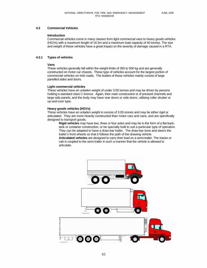
NATIONAL DIRECTORATE FOR FIRE AND EMERGENCY MANAGEMENT JUNE, 2009 RTA HANDBOOK
61
4.3 Commercial Vehicles
Introduction Commercial vehicles come in many classes from light commercial vans to heavy goods vehicles (HGVs) with a maximum length of 16.5m and a maximum load capacity of 40 tonnes. The size and weight of these vehicles have a great impact on the severity of damage caused in a RTA.
4.3.1 Types of vehicles
Vans These vehicles generally fall within the weight limits of 350 to 500 kg and are generally constructed on motor car chassis. These type of vehicles account for the largest portion of commercial vehicles on Irish roads. The bodies of these vehicles mainly consist of large panelled sides and doors.
Light commercial vehicles These vehicles have an unladen weight of under 3.05 tonnes and may be driven by persons holding a standard class C licence. Again, their main construction is of pressed channels and large side panels, and the body may have rear doors or side doors, utilising roller shutter or up-and-over type.
Heavy goods vehicles (HGVs) These vehicles have an unladen weight in excess of 3.05 tonnes and may be either rigid or articulated. They are more heavily constructed than motor cars and vans, and are specifically designed to transport goods.
Rigid vehicles may have two, three or four axles and may be in the form of a flat back, tank or container construction, or be specially built to suit a particular type of operation. They can be adapted to have a draw-bar trailer. The draw-bar tows and steers the trailer’s front wheels so that it follows the path of the drawing vehicle. Articulated vehicles are designed to carry their load on a semi-trailer. The tractor or cab is coupled to the semi trailer in such a manner that the vehicle is allowed to articulate.
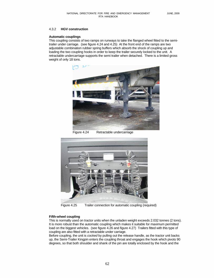
NATIONAL DIRECTORATE FOR FIRE AND EMERGENCY MANAGEMENT JUNE, 2009 RTA HANDBOOK
62
4.3.2 HGV construction Automatic couplings
This coupling consists of two ramps on runways to take the flanged wheel fitted to the semi-trailer under carriage. (see figure 4.24 and 4.25) At the front end of the ramps are two adjustable combination rubber spring buffers which absorb the shock of coupling up and loading the two coupling hooks in order to keep the trailer securely locked to the unit. A retractable undercarriage supports the semi trailer when detached. There is a limited gross weight of only 18 tons.
Figure 4.24 Retractable undercarriage
Figure 4.25 Trailer connection for automatic coupling (required)
Fifth-wheel coupling This is normally used on tractor units when the unladen weight exceeds 2.032 tonnes (2 tons). It is more robust than the automatic coupling which makes it suitable for maximum permitted load on the biggest vehicles. (see figure 4.26 and figure 4.27) Trailers fitted with this type of coupling are also fitted with a retractable under carriage. Before coupling, the unit is cocked by pulling out the release handle, as the tractor unit backs up, the Semi-Trailer Kingpin enters the coupling throat and engages the hook which pivots 90 degrees, so that both shoulder and shank of the pin are totally enclosed by the hook and the
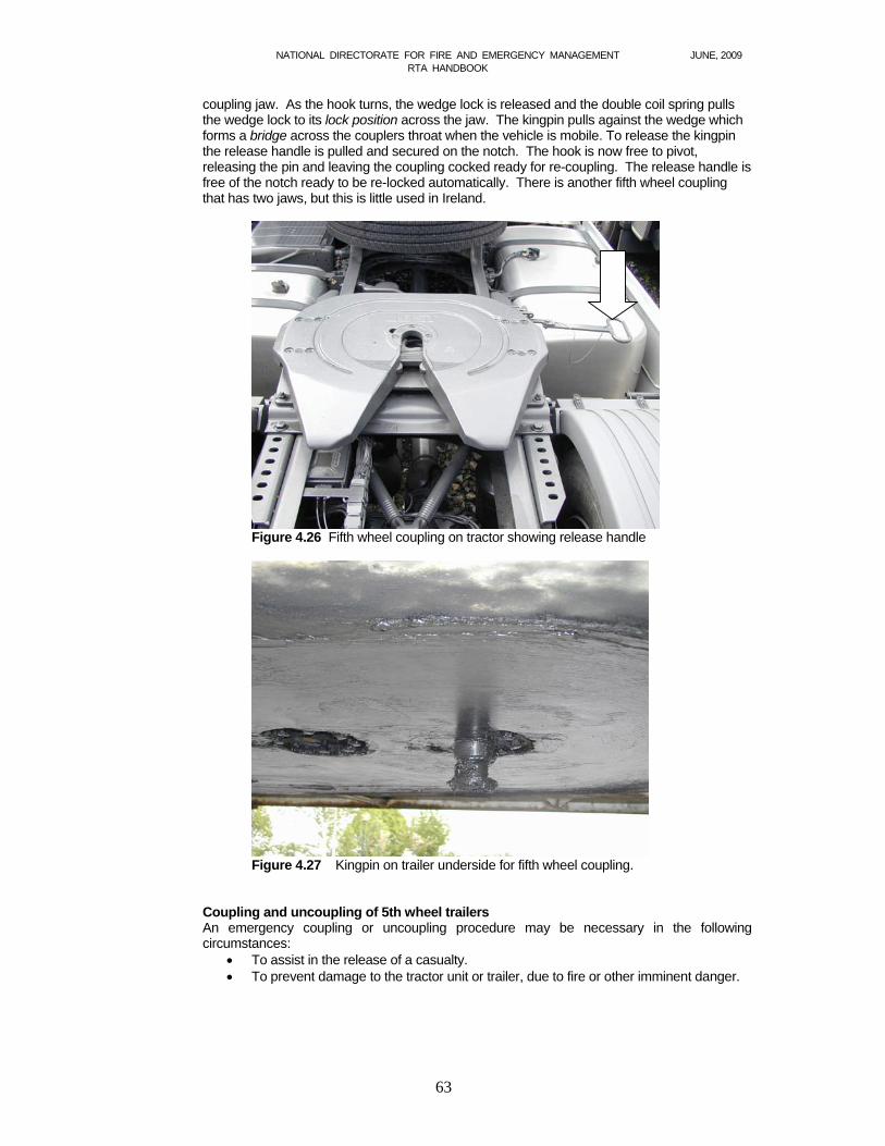
NATIONAL DIRECTORATE FOR FIRE AND EMERGENCY MANAGEMENT JUNE, 2009 RTA HANDBOOK
63
coupling jaw. As the hook turns, the wedge lock is released and the double coil spring pulls the wedge lock to its lock position across the jaw. The kingpin pulls against the wedge which forms a bridge across the couplers throat when the vehicle is mobile. To release the kingpin the release handle is pulled and secured on the notch. The hook is now free to pivot, releasing the pin and leaving the coupling cocked ready for re-coupling. The release handle is free of the notch ready to be re-locked automatically. There is another fifth wheel coupling that has two jaws, but this is little used in Ireland.
Figure 4.26 Fifth wheel coupling on tractor showing release handle
Figure 4.27 Kingpin on trailer underside for fifth wheel coupling.
Coupling and uncoupling of 5th wheel trailers An emergency coupling or uncoupling procedure may be necessary in the following circumstances:
To assist in the release of a casualty. To prevent damage to the tractor unit or trailer, due to fire or other imminent danger.

NATIONAL DIRECTORATE FOR FIRE AND EMERGENCY MANAGEMENT JUNE, 2009 RTA HANDBOOK
64
The procedure outlined below is for use in such circumstances: Uncoupling
Choose a firm, even surface. Shut off airline taps (where fitted). Disconnect airlines and electrical connections. Apply trailer parking brake (where fitted). Wind down landing gear to make contact with the ground. Release fifth wheel coupling. Pull forward slowly, watching for any excessive dipping of the trailer.
Coupling Line up tractor with trailer Check tractor and trailer heights for compatibility. Check trailer handbrake is on. Reverse tractor unit slowly under trailer listening for audible click of coupling
engaging. Pull forward slowly once or twice to confirm coupling. Apply tractor handbrake. Connect service lines and turn on air tap (where fitted). Wind up landing gear fully. Release trailer parking brake. Move away slowly.
HGV braking systems Most modern heavy goods vehicles rely on compressed air to operate the braking system. Many vehicles utilise a fail-safe system so that any loss of air pressure will automatically apply the brakes. This is achieved by the use of spring brake actuators. In normal use, a powerful spring is kept compressed by the action of an air-operated diaphragm. Any loss of air will allow the spring to extend thus mechanically operating the brakes. It is very common for damage to occur to a vehicle's braking system. The air supply is often piped to a valve at the foot brake. This is very close to the front of the vehicle and so easily becomes damaged in an impact. The end result is that the brakes lock on and the vehicle cannot be moved. Spring brakes actuators allow for manual release by rotating a bolt head with a suitable spanner. This releases the braking system and the vehicle can be moved using a controlled pull. Caution - this procedure will render the foot and hand brakes ineffective.
Service lines These are lines which transfer the services from the tractor unit to the trailer unit and are colour-coded as follows:
Colour Service Black Electrical Yellow Service brakes Red Emergency brakes (operate trailer brakes automatically on
disconnection Blue Auxiliary brakes (not always connected)
It is not always possible to rely on the colours to accurately reflect the service it is supplying as these lines are exposed and frequently covered in grease and road dirt. Each Service line has a different type of coupling to avoid incorrect connection.
Landing gear This is the term describing the retractable support fitted to the forward area of the trailer. The gear is wound down to support the trailer when uncoupled from the tractor unit. Landing gear
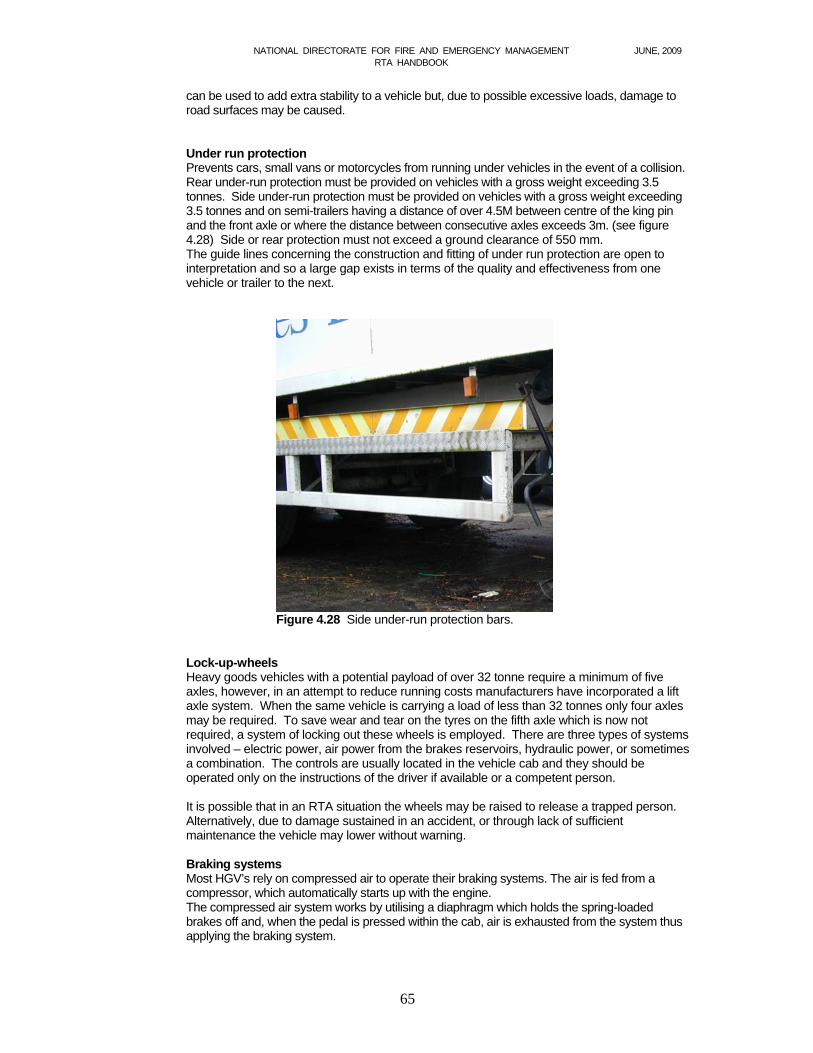
NATIONAL DIRECTORATE FOR FIRE AND EMERGENCY MANAGEMENT JUNE, 2009 RTA HANDBOOK
65
can be used to add extra stability to a vehicle but, due to possible excessive loads, damage to road surfaces may be caused.
Under run protection Prevents cars, small vans or motorcycles from running under vehicles in the event of a collision. Rear under-run protection must be provided on vehicles with a gross weight exceeding 3.5 tonnes. Side under-run protection must be provided on vehicles with a gross weight exceeding 3.5 tonnes and on semi-trailers having a distance of over 4.5M between centre of the king pin and the front axle or where the distance between consecutive axles exceeds 3m. (see figure 4.28) Side or rear protection must not exceed a ground clearance of 550 mm. The guide lines concerning the construction and fitting of under run protection are open to interpretation and so a large gap exists in terms of the quality and effectiveness from one vehicle or trailer to the next.
Figure 4.28 Side under-run protection bars.
Lock-up-wheels Heavy goods vehicles with a potential payload of over 32 tonne require a minimum of five axles, however, in an attempt to reduce running costs manufacturers have incorporated a lift axle system. When the same vehicle is carrying a load of less than 32 tonnes only four axles may be required. To save wear and tear on the tyres on the fifth axle which is now not required, a system of locking out these wheels is employed. There are three types of systems involved – electric power, air power from the brakes reservoirs, hydraulic power, or sometimes a combination. The controls are usually located in the vehicle cab and they should be operated only on the instructions of the driver if available or a competent person.
It is possible that in an RTA situation the wheels may be raised to release a trapped person. Alternatively, due to damage sustained in an accident, or through lack of sufficient maintenance the vehicle may lower without warning. Braking systems Most HGV’s rely on compressed air to operate their braking systems. The air is fed from a compressor, which automatically starts up with the engine. The compressed air system works by utilising a diaphragm which holds the spring-loaded brakes off and, when the pedal is pressed within the cab, air is exhausted from the system thus applying the braking system.
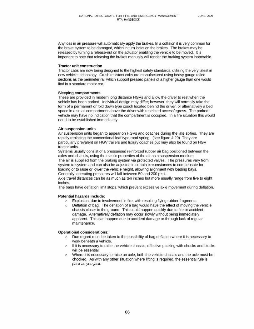
NATIONAL DIRECTORATE FOR FIRE AND EMERGENCY MANAGEMENT JUNE, 2009 RTA HANDBOOK
66
Any loss in air pressure will automatically apply the brakes. In a collision it is very common for the brake system to be damaged, which in turn locks on the brakes. The brakes may be released by turning a release-nut on the actuator enabling the vehicle to be moved. It is important to note that releasing the brakes manually will render the braking system inoperable. Tractor unit construction Tractor cabs are now being designed to the highest safety standards, utilising the very latest in new vehicle technology. Crush resistant cabs are manufactured using heavy gauge rolled sections as the perimeter rail which support pressed panels of a higher gauge than one would find in a standard motor car. Sleeping compartments These are provided in modern long distance HGVs and allow the driver to rest when the vehicle has been parked. Individual design may differ; however, they will normally take the form of a permanent or fold down type couch located behind the driver, or alternatively a bed space in a small compartment above the driver with restricted access/egress. The parked vehicle may have no indication that the compartment is occupied. In a fire situation this would need to be established immediately.
Air suspension units Air suspension units began to appear on HGVs and coaches during the late sixties. They are rapidly replacing the conventional leaf type road spring. (see figure 4.29) They are particularly prevalent on HGV trailers and luxury coaches but may also be found on HGV tractor units. Systems usually consist of a pressurised reinforced rubber air bag positioned between the axles and chassis, using the elastic properties of the air as a suspension medium. The air is supplied from the braking system via protected valves. The pressures vary from system to system and can also be adjusted in certain circumstances to compensate for loading or to raise or lower the vehicle height, allowing alignment with loading bays. Generally, operating pressures will fall between 50 and 200 p.s.i. Axle travel distances can be as much as ten inches but more usually range from five to eight inches. The bags have deflation limit stops, which prevent excessive axle movement during deflation.
Potential hazards include:
o Explosion, due to involvement in fire, with resulting flying rubber fragments. o Deflation of bag. The deflation of a bag would have the effect of moving the vehicle
chassis closer to the ground. This could happen quickly due to fire or accident damage. Alternatively deflation may occur slowly without being immediately apparent. This can happen due to accident damage or through lack of regular maintenance.
Operational considerations: o Due regard must be taken to the possibility of bag deflation where it is necessary to
work beneath a vehicle. o If it is necessary to raise the vehicle chassis, effective packing with chocks and blocks
will be essential. o Where it is necessary to raise an axle, both the vehicle chassis and the axle must be
chocked. As with any other situation where lifting is required, the essential rule is pack as you jack.
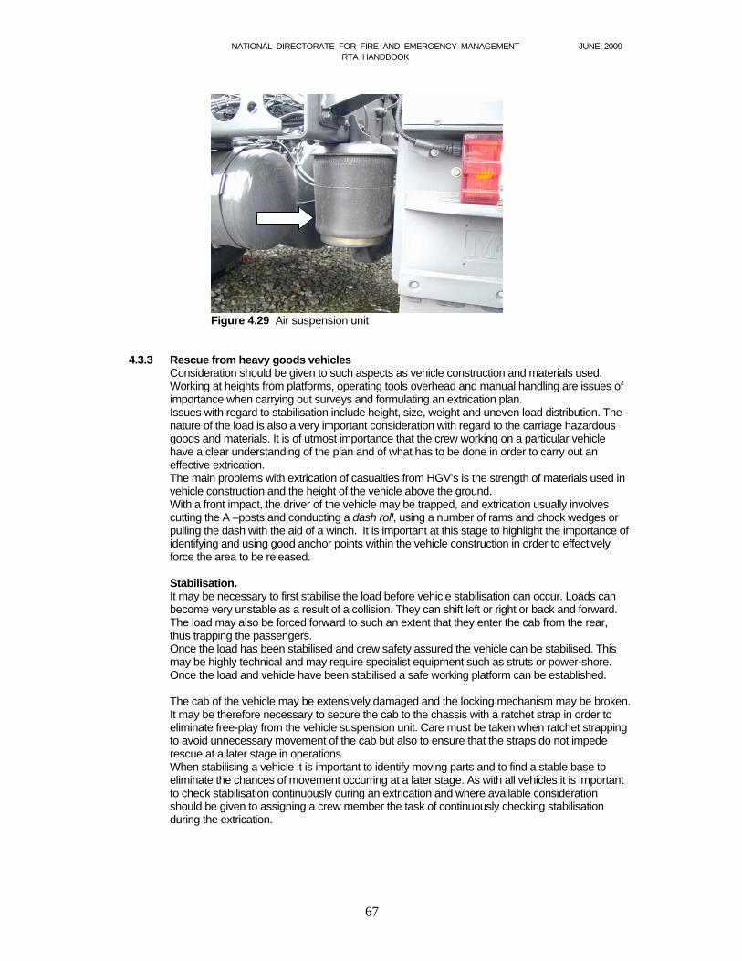
NATIONAL DIRECTORATE FOR FIRE AND EMERGENCY MANAGEMENT JUNE, 2009 RTA HANDBOOK
67
Figure 4.29 Air suspension unit 4.3.3 Rescue from heavy goods vehicles
Consideration should be given to such aspects as vehicle construction and materials used. Working at heights from platforms, operating tools overhead and manual handling are issues of importance when carrying out surveys and formulating an extrication plan. Issues with regard to stabilisation include height, size, weight and uneven load distribution. The nature of the load is also a very important consideration with regard to the carriage hazardous goods and materials. It is of utmost importance that the crew working on a particular vehicle have a clear understanding of the plan and of what has to be done in order to carry out an effective extrication. The main problems with extrication of casualties from HGV’s is the strength of materials used in vehicle construction and the height of the vehicle above the ground. With a front impact, the driver of the vehicle may be trapped, and extrication usually involves cutting the A –posts and conducting a dash roll, using a number of rams and chock wedges or pulling the dash with the aid of a winch. It is important at this stage to highlight the importance of identifying and using good anchor points within the vehicle construction in order to effectively force the area to be released.
Stabilisation. It may be necessary to first stabilise the load before vehicle stabilisation can occur. Loads can become very unstable as a result of a collision. They can shift left or right or back and forward. The load may also be forced forward to such an extent that they enter the cab from the rear, thus trapping the passengers. Once the load has been stabilised and crew safety assured the vehicle can be stabilised. This may be highly technical and may require specialist equipment such as struts or power-shore. Once the load and vehicle have been stabilised a safe working platform can be established.
The cab of the vehicle may be extensively damaged and the locking mechanism may be broken. It may be therefore necessary to secure the cab to the chassis with a ratchet strap in order to eliminate free-play from the vehicle suspension unit. Care must be taken when ratchet strapping to avoid unnecessary movement of the cab but also to ensure that the straps do not impede rescue at a later stage in operations. When stabilising a vehicle it is important to identify moving parts and to find a stable base to eliminate the chances of movement occurring at a later stage. As with all vehicles it is important to check stabilisation continuously during an extrication and where available consideration should be given to assigning a crew member the task of continuously checking stabilisation during the extrication.
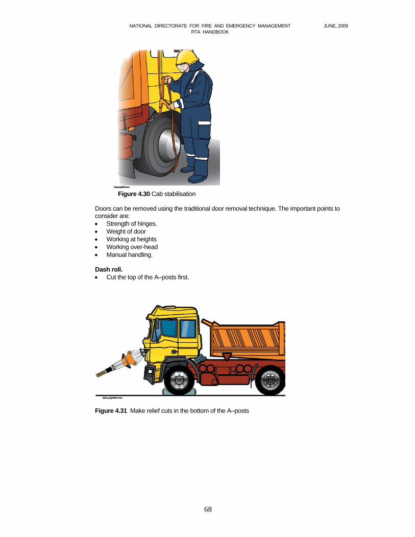
NATIONAL DIRECTORATE FOR FIRE AND EMERGENCY MANAGEMENT JUNE, 2009 RTA HANDBOOK
68
Figure 4.30 Cab stabilisation
Doors can be removed using the traditional door removal technique. The important points to consider are: Strength of hinges. Weight of door Working at heights Working over-head Manual handling.
Dash roll. Cut the top of the A–posts first.
Figure 4.31 Make relief cuts in the bottom of the A–posts
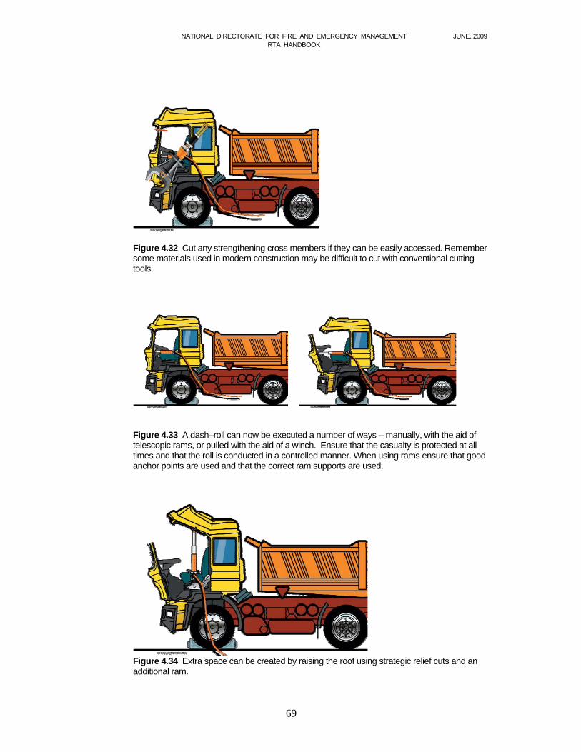
NATIONAL DIRECTORATE FOR FIRE AND EMERGENCY MANAGEMENT JUNE, 2009 RTA HANDBOOK
69
Figure 4.32 Cut any strengthening cross members if they can be easily accessed. Remember some materials used in modern construction may be difficult to cut with conventional cutting tools.
Figure 4.33 A dash–roll can now be executed a number of ways – manually, with the aid of telescopic rams, or pulled with the aid of a winch. Ensure that the casualty is protected at all times and that the roll is conducted in a controlled manner. When using rams ensure that good anchor points are used and that the correct ram supports are used.
Figure 4.34 Extra space can be created by raising the roof using strategic relief cuts and an additional ram.
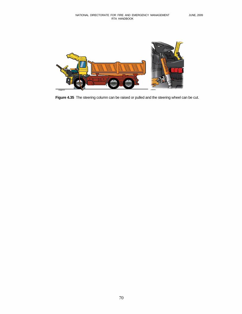
NATIONAL DIRECTORATE FOR FIRE AND EMERGENCY MANAGEMENT JUNE, 2009 RTA HANDBOOK
70
Figure 4.35 The steering column can be raised or pulled and the steering wheel can be cut.

NATIONAL DIRECTORATE FOR FIRE AND EMERGENCY MANAGEMENT JUNE, 2009 RTA HANDBOOK
71
Buses
Figure 4.32
Buses and coaches Buses are often put in the category of heavy vehicles, but have a different construction when compared with trucks. The bus compartment is very vulnerable in the case of a collision. It is positioned on a chassis consisting of longitudinal beams and a criss-cross pattern of pipes or beams, welded together, on which the outside cover (steel plate or fibreglass) is fixed. The construction often fails to withstand the forces exerted on it in the event of a crash. This can lead to the potential entrapment of large numbers of casualties. The seats inside the bus often fail due to the forces of the crash, further entrapping casualties.
Figure 4.33
Gaining access After the stabilisation phase, the next obvious task is to gain access to the bus. This can be achieved in various ways, the simplest of which would be to use the doors, windows or emergency exits on the roof. Gaining access allows the Incident Commander opportunity to evaluate the severity of the incident, and will enable assessment of the number of casualties and nature of the injuries sustained to those involved. It should be ensured that a check is carried out of the luggage compartments, as well as the beds and toilets, if the bus is equipped with these. Scene management Due to the fact that in many bus incidents there are a large number of casualties, it is important to define roles in the rescue team and to detail clear working zones. Effective triage will enable treatment of the most appropriate casualties first.
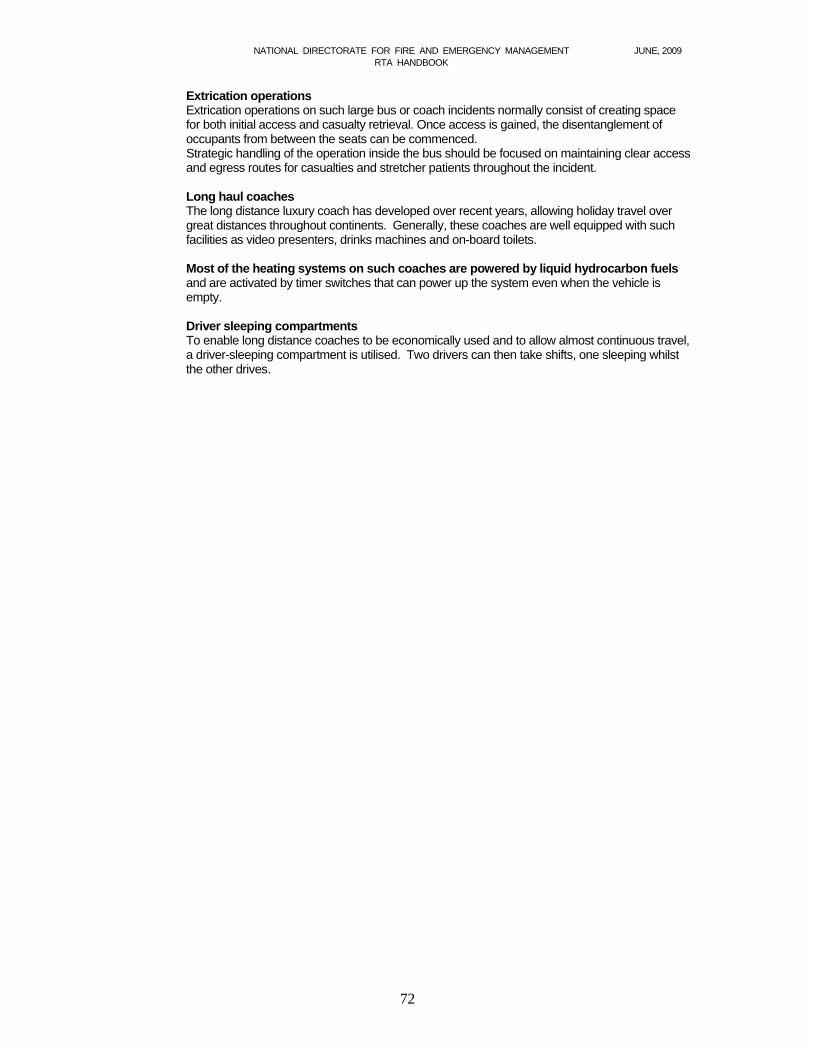
NATIONAL DIRECTORATE FOR FIRE AND EMERGENCY MANAGEMENT JUNE, 2009 RTA HANDBOOK
72
Extrication operations Extrication operations on such large bus or coach incidents normally consist of creating space for both initial access and casualty retrieval. Once access is gained, the disentanglement of occupants from between the seats can be commenced. Strategic handling of the operation inside the bus should be focused on maintaining clear access and egress routes for casualties and stretcher patients throughout the incident. Long haul coaches The long distance luxury coach has developed over recent years, allowing holiday travel over great distances throughout continents. Generally, these coaches are well equipped with such facilities as video presenters, drinks machines and on-board toilets. Most of the heating systems on such coaches are powered by liquid hydrocarbon fuels and are activated by timer switches that can power up the system even when the vehicle is empty. Driver sleeping compartments To enable long distance coaches to be economically used and to allow almost continuous travel, a driver-sleeping compartment is utilised. Two drivers can then take shifts, one sleeping whilst the other drives.
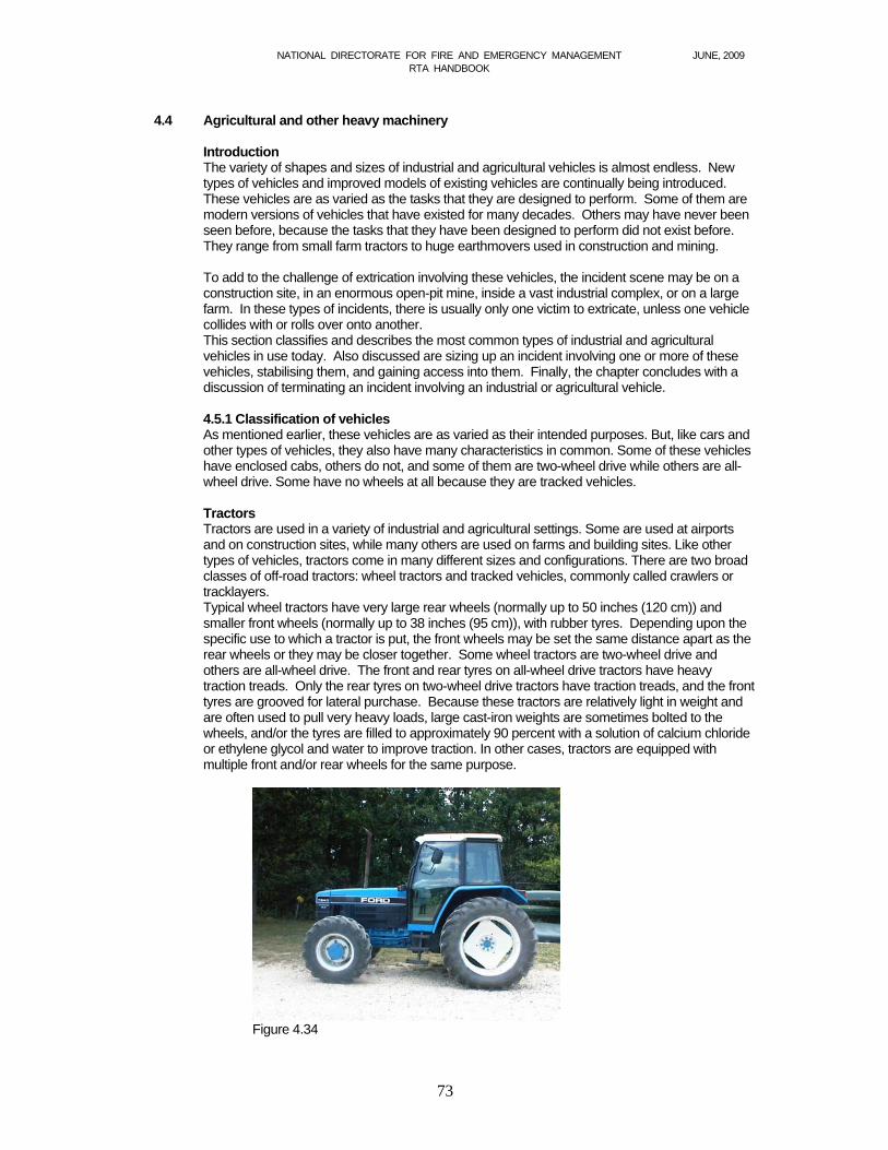
NATIONAL DIRECTORATE FOR FIRE AND EMERGENCY MANAGEMENT JUNE, 2009 RTA HANDBOOK
73
4.4 Agricultural and other heavy machinery
Introduction The variety of shapes and sizes of industrial and agricultural vehicles is almost endless. New types of vehicles and improved models of existing vehicles are continually being introduced. These vehicles are as varied as the tasks that they are designed to perform. Some of them are modern versions of vehicles that have existed for many decades. Others may have never been seen before, because the tasks that they have been designed to perform did not exist before. They range from small farm tractors to huge earthmovers used in construction and mining. To add to the challenge of extrication involving these vehicles, the incident scene may be on a construction site, in an enormous open-pit mine, inside a vast industrial complex, or on a large farm. In these types of incidents, there is usually only one victim to extricate, unless one vehicle collides with or rolls over onto another. This section classifies and describes the most common types of industrial and agricultural vehicles in use today. Also discussed are sizing up an incident involving one or more of these vehicles, stabilising them, and gaining access into them. Finally, the chapter concludes with a discussion of terminating an incident involving an industrial or agricultural vehicle. 4.5.1 Classification of vehicles As mentioned earlier, these vehicles are as varied as their intended purposes. But, like cars and other types of vehicles, they also have many characteristics in common. Some of these vehicles have enclosed cabs, others do not, and some of them are two-wheel drive while others are all-wheel drive. Some have no wheels at all because they are tracked vehicles. Tractors Tractors are used in a variety of industrial and agricultural settings. Some are used at airports and on construction sites, while many others are used on farms and building sites. Like other types of vehicles, tractors come in many different sizes and configurations. There are two broad classes of off-road tractors: wheel tractors and tracked vehicles, commonly called crawlers or tracklayers. Typical wheel tractors have very large rear wheels (normally up to 50 inches (120 cm)) and smaller front wheels (normally up to 38 inches (95 cm)), with rubber tyres. Depending upon the specific use to which a tractor is put, the front wheels may be set the same distance apart as the rear wheels or they may be closer together. Some wheel tractors are two-wheel drive and others are all-wheel drive. The front and rear tyres on all-wheel drive tractors have heavy traction treads. Only the rear tyres on two-wheel drive tractors have traction treads, and the front tyres are grooved for lateral purchase. Because these tractors are relatively light in weight and are often used to pull very heavy loads, large cast-iron weights are sometimes bolted to the wheels, and/or the tyres are filled to approximately 90 percent with a solution of calcium chloride or ethylene glycol and water to improve traction. In other cases, tractors are equipped with multiple front and/or rear wheels for the same purpose.
Figure 4.34
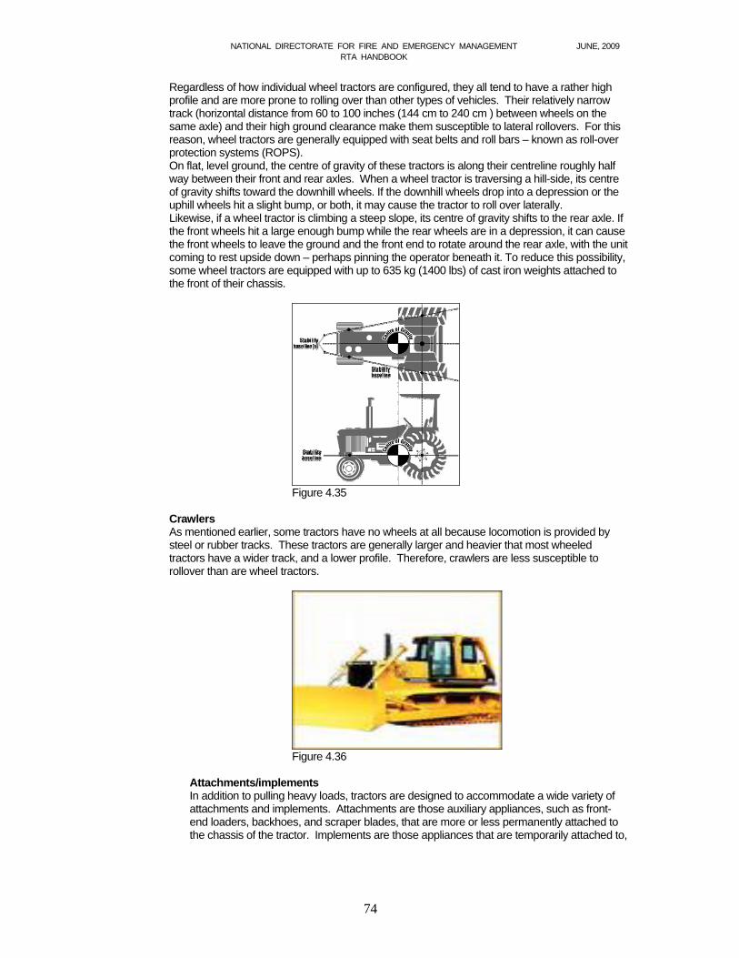
NATIONAL DIRECTORATE FOR FIRE AND EMERGENCY MANAGEMENT JUNE, 2009 RTA HANDBOOK
74
Regardless of how individual wheel tractors are configured, they all tend to have a rather high profile and are more prone to rolling over than other types of vehicles. Their relatively narrow track (horizontal distance from 60 to 100 inches (144 cm to 240 cm ) between wheels on the same axle) and their high ground clearance make them susceptible to lateral rollovers. For this reason, wheel tractors are generally equipped with seat belts and roll bars – known as roll-over protection systems (ROPS). On flat, level ground, the centre of gravity of these tractors is along their centreline roughly half way between their front and rear axles. When a wheel tractor is traversing a hill-side, its centre of gravity shifts toward the downhill wheels. If the downhill wheels drop into a depression or the uphill wheels hit a slight bump, or both, it may cause the tractor to roll over laterally. Likewise, if a wheel tractor is climbing a steep slope, its centre of gravity shifts to the rear axle. If the front wheels hit a large enough bump while the rear wheels are in a depression, it can cause the front wheels to leave the ground and the front end to rotate around the rear axle, with the unit coming to rest upside down – perhaps pinning the operator beneath it. To reduce this possibility, some wheel tractors are equipped with up to 635 kg (1400 lbs) of cast iron weights attached to the front of their chassis.
Figure 4.35
Crawlers As mentioned earlier, some tractors have no wheels at all because locomotion is provided by steel or rubber tracks. These tractors are generally larger and heavier that most wheeled tractors have a wider track, and a lower profile. Therefore, crawlers are less susceptible to rollover than are wheel tractors.
Figure 4.36
Attachments/implements In addition to pulling heavy loads, tractors are designed to accommodate a wide variety of attachments and implements. Attachments are those auxiliary appliances, such as front-end loaders, backhoes, and scraper blades, that are more or less permanently attached to the chassis of the tractor. Implements are those appliances that are temporarily attached to,
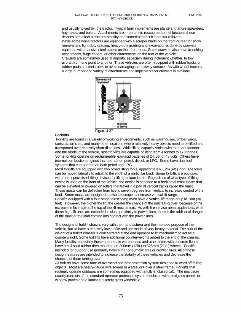
NATIONAL DIRECTORATE FOR FIRE AND EMERGENCY MANAGEMENT JUNE, 2009 RTA HANDBOOK
75
and usually towed by, the tractor. Typical farm implements are planters, manure spreaders, hay rakes, and balers. Attachments are important to rescue personnel because these devices can affect a tractor’s stability and sometimes result in tractor rollovers. While some wheel tractors are equipped with a scraper blade on the front or rear for snow removal and light-duty grading, heavy-duty grading and excavation is done by crawlers equipped with massive steel blades on their front ends. Some crawlers also have trenching attachments, huge rippers, or other attachments on the rear of the vehicle. Crawlers are sometimes used at airports, especially during inclement whether, to tow aircraft from one point to another. These vehicles are often equipped with rubber tracks or rubber pads on steel tracks to avoid damaging the taxiway surface. As with wheel tractors, a large number and variety of attachments and implements for crawlers is available.
Figure 4.37
Forklifts Forklifts are found in a variety of working environments, such as warehouses, timber yards, construction sites, and many other locations where relatively heavy objects need to be lifted and transported over relatively short distances. While lifting capacity varies with the manufacturer and the model of the vehicle, most forklifts are capable of lifting from 4 tonnes to 170 tonnes. Some forklifts operate on rechargeable lead-acid batteries of 24, 36, or 48 volts. Others have internal combustion engines that operate on petrol, diesel, or LPG. Some have dual fuel systems that can operate on both petrol and LPG. Most forklifts are equipped with two broad lifting forks, approximately 1.2m (4ft.) long. The forks can be moved laterally to adjust to the width of a particular load. Some forklifts are equipped with more specialised lifting devices for lifting unique loads. Regardless of what type of lifting device is used on the front of the vehicle, the device is attached to a horizontal cross beam that can be elevated or lowered on rollers that travel in a pair of vertical tracks called the mast. These masts can be deflected from five to seven degrees from vertical to increase control of the load. Some masts are designed to also telescope to increase vertical lift range. Forklifts equipped with a four-stage telescoping mast have a vertical lift range of up to 10m (30 feet). However, the higher the lift, the greater the chance of the unit falling over, because of the increase in leverage at the top of the lift mechanism. As with fire service aerial appliances, when these high-lift units are extended in close proximity to power lines, there is the additional danger of the mast or the load coming into contact with the power lines. The designs of forklift chassis vary with the manufacturer and the intended purpose of the vehicle, but all have a relatively low profile and are made of very heavy material. The bulk of the weight of a forklift chassis is concentrated at the end opposite to lift mechanism to act as a counterweight. Some forklifts have additional counterweights added to the end of the chassis. Many forklifts, especially those operated in warehouses and other areas with concrete floors, have small solid rubber tires mounted on 300mm (12in.) to 525mm (21in.) wheels. Forklifts intended for outdoor use generally have either pneumatic tires or cushion tires. All of these design features are intended to increase the stability of these vehicles and decrease the chances of them turning over. All forklifts have some form of overhead operator protection system designed to ward off falling objects. Most are heavy-gauge wire screen or a steel grill over a steel frame. Forklifts that routinely operate outdoors are sometimes equipped with a fully enclosed cab. The enclosure usually consists of the standard operator protection system enclosed with plexiglass panels or window panes and a laminated safety glass windshield.
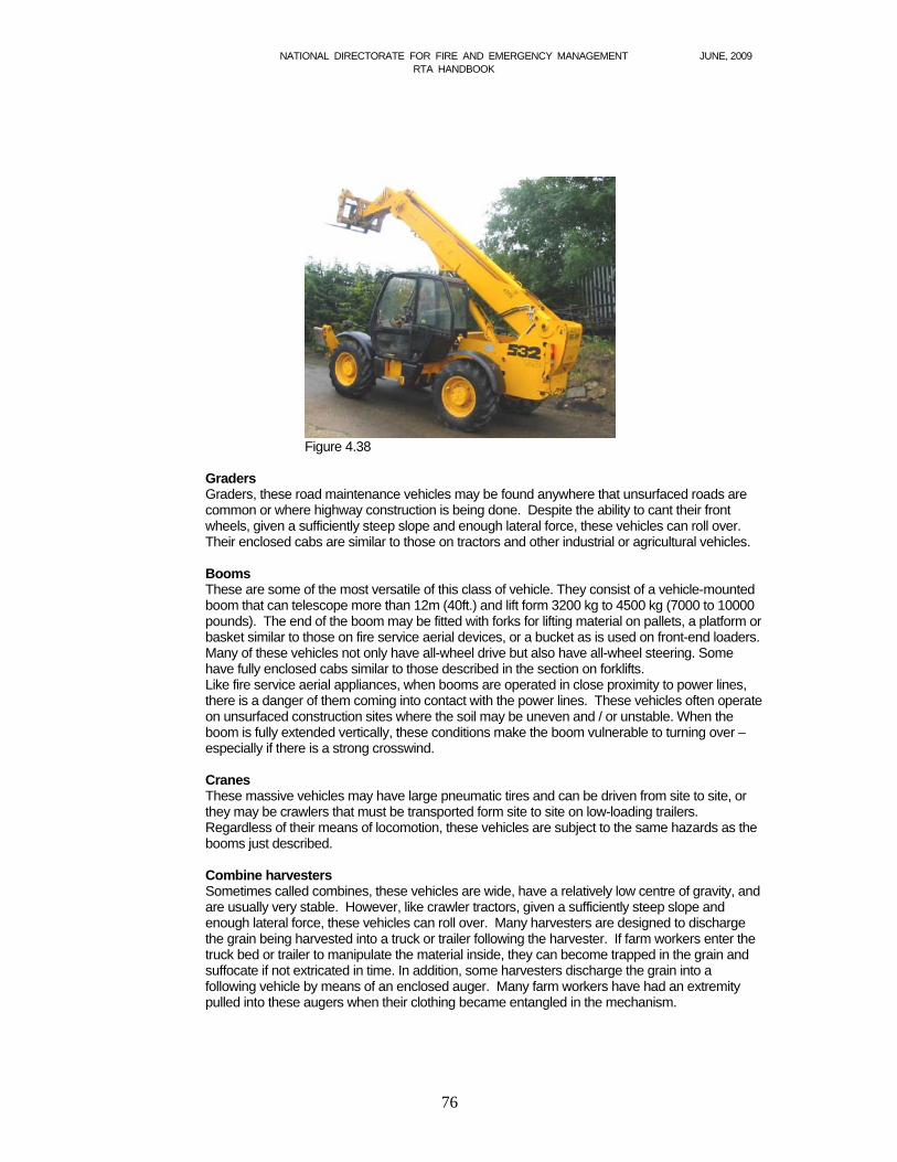
NATIONAL DIRECTORATE FOR FIRE AND EMERGENCY MANAGEMENT JUNE, 2009 RTA HANDBOOK
76
Figure 4.38
Graders Graders, these road maintenance vehicles may be found anywhere that unsurfaced roads are common or where highway construction is being done. Despite the ability to cant their front wheels, given a sufficiently steep slope and enough lateral force, these vehicles can roll over. Their enclosed cabs are similar to those on tractors and other industrial or agricultural vehicles. Booms These are some of the most versatile of this class of vehicle. They consist of a vehicle-mounted boom that can telescope more than 12m (40ft.) and lift form 3200 kg to 4500 kg (7000 to 10000 pounds). The end of the boom may be fitted with forks for lifting material on pallets, a platform or basket similar to those on fire service aerial devices, or a bucket as is used on front-end loaders. Many of these vehicles not only have all-wheel drive but also have all-wheel steering. Some have fully enclosed cabs similar to those described in the section on forklifts. Like fire service aerial appliances, when booms are operated in close proximity to power lines, there is a danger of them coming into contact with the power lines. These vehicles often operate on unsurfaced construction sites where the soil may be uneven and / or unstable. When the boom is fully extended vertically, these conditions make the boom vulnerable to turning over – especially if there is a strong crosswind. Cranes These massive vehicles may have large pneumatic tires and can be driven from site to site, or they may be crawlers that must be transported form site to site on low-loading trailers. Regardless of their means of locomotion, these vehicles are subject to the same hazards as the booms just described. Combine harvesters Sometimes called combines, these vehicles are wide, have a relatively low centre of gravity, and are usually very stable. However, like crawler tractors, given a sufficiently steep slope and enough lateral force, these vehicles can roll over. Many harvesters are designed to discharge the grain being harvested into a truck or trailer following the harvester. If farm workers enter the truck bed or trailer to manipulate the material inside, they can become trapped in the grain and suffocate if not extricated in time. In addition, some harvesters discharge the grain into a following vehicle by means of an enclosed auger. Many farm workers have had an extremity pulled into these augers when their clothing became entangled in the mechanism.
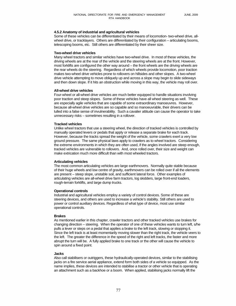
NATIONAL DIRECTORATE FOR FIRE AND EMERGENCY MANAGEMENT JUNE, 2009 RTA HANDBOOK
77
4.5.2 Anatomy of industrial and agricultural vehicles Some of these vehicles can be differentiated by their means of locomotion- two-wheel drive, all-wheel drive, or tracklayers. Others are differentiated by their configuration – articulating booms, telescoping booms, etc. Still others are differentiated by their sheer size. Two-wheel drive vehicles Many wheel tractors and similar vehicles have two-wheel drive. In most of these vehicles, the driving wheels are at the rear of the vehicle and the steering wheels are at the front. However, most forklifts are configured the other way around – the front wheels are the driving wheels are the rear wheels do the steering. Regardless of which wheels provide locomotion, poor traction makes two-wheel drive vehicles prone to rollovers on hillsides and other slopes. A two-wheel drive vehicle attempting to move obliquely up and across a slope may begin to slide sideways and then down slope. If it hits an obstruction while moving in this way, the vehicle may roll over.
All-wheel drive vehicles Four-wheel or all-wheel drive vehicles are much better equipped to handle situations involving poor traction and steep slopes. Some of these vehicles have all wheel steering as well. These are especially agile vehicles that are capable of some extraordinary manoeuvres. However, because all-wheel drive vehicles are so capable and so manoeuvrable, their drivers can be lulled into a false sense of invulnerability. Such a cavalier attitude can cause the operator to take unnecessary risks – sometimes resulting in a rollover. Tracked vehicles Unlike wheel tractors that use a steering wheel, the direction of tracked vehicles is controlled by manually operated levers or pedals that apply or release a separate brake for each track. However, because the tracks spread the weight of the vehicle, some crawlers exert a very low ground pressure. The same physical laws apply to crawlers as to wheel tractors. Considering the extreme environments in which they are often used, if the angles involved are steep enough, tracked vehicles are vulnerable to rollovers. And, once rolled over, their size and weight can make extrication much more difficult than with most wheeled tractors. Articulating vehicles The most common articulating vehicles are large earthmovers. Normally quite stable because of their huge wheels and low centre of gravity, earthmovers can be rolled over if all the elements are present – steep slope, unstable soil, and sufficient lateral force. Other examples of articulating vehicles are all-wheel drive farm tractors, log skidders, large front-end loaders, rough-terrain forklifts, and large dump trucks. Operational controls Industrial and agricultural vehicles employ a variety of control devices. Some of these are steering devices, and others are used to increase a vehicle’s stability. Still others are used to power or control auxiliary devices. Regardless of what type of device, most use similar operational controls. Brakes As mentioned earlier in this chapter, crawler tractors and other tracked vehicles use brakes for changing direction – steering. When the operator of one of these vehicles wants to turn left, s/he pulls a lever or steps on a pedal that applies a brake to the left track, slowing or stopping it. Since the left track is at least momentarily moving slower than the right track, the vehicle veers to the left. The greater the difference in the speed of the right and left tracks, the faster and more abrupt the turn will be. A fully applied brake to one track or the other will cause the vehicle to spin around a fixed point. Jacks Also call stabilisers or outriggers, these hydraulically-operated devices, similar to the stabilising jacks on a fire service aerial appliance, extend form both sides of a vehicle so equipped. As the name implies, these devices are intended to stabilise a tractor or other vehicle that is operating an attachment such as a backhoe or a boom. When applied, stabilising jacks normally lift the
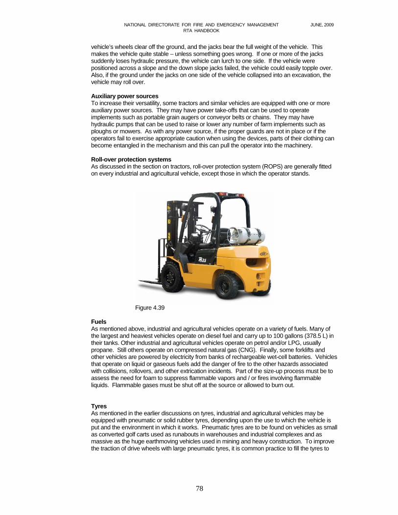
NATIONAL DIRECTORATE FOR FIRE AND EMERGENCY MANAGEMENT JUNE, 2009 RTA HANDBOOK
78
vehicle’s wheels clear off the ground, and the jacks bear the full weight of the vehicle. This makes the vehicle quite stable – unless something goes wrong. If one or more of the jacks suddenly loses hydraulic pressure, the vehicle can lurch to one side. If the vehicle were positioned across a slope and the down slope jacks failed, the vehicle could easily topple over. Also, if the ground under the jacks on one side of the vehicle collapsed into an excavation, the vehicle may roll over. Auxiliary power sources To increase their versatility, some tractors and similar vehicles are equipped with one or more auxiliary power sources. They may have power take-offs that can be used to operate implements such as portable grain augers or conveyor belts or chains. They may have hydraulic pumps that can be used to raise or lower any number of farm implements such as ploughs or mowers. As with any power source, if the proper guards are not in place or if the operators fail to exercise appropriate caution when using the devices, parts of their clothing can become entangled in the mechanism and this can pull the operator into the machinery. Roll-over protection systems As discussed in the section on tractors, roll-over protection system (ROPS) are generally fitted on every industrial and agricultural vehicle, except those in which the operator stands.
Figure 4.39 Fuels As mentioned above, industrial and agricultural vehicles operate on a variety of fuels. Many of the largest and heaviest vehicles operate on diesel fuel and carry up to 100 gallons (378.5 L) in their tanks. Other industrial and agricultural vehicles operate on petrol and/or LPG, usually propane. Still others operate on compressed natural gas (CNG). Finally, some forklifts and other vehicles are powered by electricity from banks of rechargeable wet-cell batteries. Vehicles that operate on liquid or gaseous fuels add the danger of fire to the other hazards associated with collisions, rollovers, and other extrication incidents. Part of the size-up process must be to assess the need for foam to suppress flammable vapors and / or fires involving flammable liquids. Flammable gases must be shut off at the source or allowed to burn out.
Tyres As mentioned in the earlier discussions on tyres, industrial and agricultural vehicles may be equipped with pneumatic or solid rubber tyres, depending upon the use to which the vehicle is put and the environment in which it works. Pneumatic tyres are to be found on vehicles as small as converted golf carts used as runabouts in warehouses and industrial complexes and as massive as the huge earthmoving vehicles used in mining and heavy construction. To improve the traction of drive wheels with large pneumatic tyres, it is common practice to fill the tyres to
NATIONAL DIRECTORATE FOR FIRE AND EMERGENCY MANAGEMENT JUNE, 2009 RTA HANDBOOK
79
about 90 percent with water or some other inert fluid, and than inflate the tyres to their normal operation pressure with air. Some forklifts and similar vehicles have what are called cushion tyres. These are solid rubber tyres that look like the pneumatic tires used on cars and light trucks. One obvious difference between a cushion tyre and a pneumatic tyre is the absence of a valve stem on the cushion tyre. Other solid rubber tyres on fork lifts are quite obvious for what they are. They generally are smaller in diameter than either cushion or pneumatic tyres, and they usually have no traction treads. 4.5.3 Agricultural incident size-up As described in section 1, the size-up of an extrication incident involving an industrial or agricultural vehicle should be done systematically beginning with an assessment of the scene. This should be followed by an assessment of the vehicles involved, the trapped victims, and the extrication requirements of the particular incident. As always, size-up continues throughout the incident. Scene assessment The first-responding Incident Commander must factor the effects of time, day, date, and weather into his/her assessment before ever reaching the incident scene. For example, if an incident involving an industrial vehicle is reported during normal working hours, on a weekday, in the summer, how are these variables likely to affect the incident? Will the scene be congested with curious colleagues? Will some of them try to extricate their fellow worker, perhaps causing the victim further harm and making the situation worse? Will the prevailing weather expose rescuers and trapped victims to extremes of temperature and / or humidity? On the other hand, if the incident is reported during night-time or on a holiday, when the bulk of the workforce is likely to be absent, will there be enough technical support or should company management and /or special equipment operators be asked to respond? Will additional lighting be needed? If the incident involves an overturned farm vehicle or entrapment in some other piece of farm machinery, is the incident location clearly known and readily accessible, or will rescue personnel have to search for the scene? Is the trapped operator the only person at the scene who is familiar with the operation of the machine, and will farm advisors or other experts be needed? Will the remoteness of the scene require that a helicopter be called? Finally, as the Incident Commander nears the scene, s/he should look for anything unusual that might indicate other collateral problems. Is smoke (especially that with an unusual colour) or steam rising from the scene? Will fire protection be a higher than normal priority because of a known flammability hazard? Will large-scale foam-making capability be needed? Will hazardous materials equipment be needed because of a known release or a high potential for the release of a pesticide or other substance? What additional resources will be need de to control and mitigate the known ad potential hazards in this incident? What ever those resources are, they should be requested immediately. Vehicle assessment Once on the scene, if there appears to be a legitimate emergency, the first Incident Commander should assume command of the incident and make a more detailed assessment of the vehicles involved. To make a thorough assessment, the officer must attempt to answer a number of critical questions. Is there more than one vehicle involved? Was there a collision, or did one vehicle roll over onto the other? What type of vehicle is involved? What is its position? Was the vehicle lifting or carrying some heavy load and if so, is the load a hazard to rescuers, tapped victims, or others? Are there potential hazards because of springs, cams or weights that are a part of the vehicle or in close proximity to it? Is the vehicle leaking flammable or combustible liquids or other hazardous materials? Does the scene need to be cordoned off, or is it sufficiently isolated to reduce the need to control access to the scene? Victim assessment As mentioned earlier, in most incidents involving industrial and agricultural vehicles, there will only be one occupant in each vehicle. However, the size and weight of these vehicles may make extrication one victim more challenging and time consuming than extricating several from
NATIONAL DIRECTORATE FOR FIRE AND EMERGENCY MANAGEMENT JUNE, 2009 RTA HANDBOOK
80
more conventional vehicles. As always, this phase of the size-up process involves looking for victims to determine how many there are, where they are, and what their medical conditions are. Even though an industrial or agricultural vehicle may seem very stable in its present position, rescuers must attempt to assess the trapped victims without jostling the vehicle – especially the vehicle’s cab. Extrication assessment Once all trapped victims have been located and their conditions assessed, a decision must be made about how they can be extricated from the vehicle in the safest, fastest, and most efficient way. This means assessing the types of extrication tools and equipment that are likely to be needed to free the trapped victims. Are there a sufficient number of power spreaders, cutters, and other similar tools on scene, or do more or different types need to be requested? Are there a sufficient number of rescue personnel on scene, or will more be needed? 4.5.4 Agricultural vehicle stabilisation Because of the size and weight of many of these vehicles, they are generally quite stable. However, following a collision or rollover, these vehicles must be assumed to be unstable. Like any other vehicle from which one or more victims must be extricated, an industrial or agricultural vehicle must be stabilised before rescue personnel can enter to assess, stabilise, package, and disentangle trapped victims. As with other types of vehicles, the techniques and equipment used to stabilise an industrial or agricultural vehicle may vary depending upon how the vehicle came to rest – upright, on its side, on its roof, or in some other position.
Vehicle upright Unlike automobiles and light trucks, when an industrial or agricultural vehicle is upright following a collision or other destructive event, it is likely to be very stable vertically. This is because of the extremely heavy suspension, or absence of suspension, on may of these vehicles. However, because the destructive event many have damaged or destroyed the vehicle’s suspension system (if any), the same vertical stabilisation measures described earlier should be applied. In addition, the vehicle should be stabilized horizontally using chocks, wedges, etc., to immobilize the wheels. Both vertical and horizontal stabilization may involve the usual equipment and techniques-four-point or six-point cribbing, timber shores or pneumatic shores, installed at the appropriate points. In addition, wheel chocks, wedges, and/or webbing and chains may be needed to provide horizontal stability. How and where these techniques are applied will depend on the specifics of the situation. Vehicle on its side Just as with heavy trucks, once industrial or agricultural vehicles roll onto their sides they may appear to be very stable. However, as with the other types, if the vehicle has come to rest on a slope or on unstable soil, there is the ever present danger of it suddenly and unexpectedly rolling back onto its wheels or tracks, or onto its top. Therefore, to create a safe working environment for rescue personnel, it may be necessary to first secure the vehicle from the top with webbing and or chains attached to a secure anchor point. Then, with that anti-roll protection in place, shoring can be installed on the underside of the vehicle. Vehicle upside down Since many industrial and agricultural vehicles do not have roofs, the vehicle may be resting on a roll bar or on its fenders. Regardless of what part of the vehicle is supporting the rest of it, an industrial or agricultural vehicle in this position is likely to be very unstable. This is because the vehicle’s centre of gravity is relatively high in the position. Therefore, it is imperative that the vehicle be effectively stabilised as soon as possible. Stabilising an upside down industrial or agricultural vehicle may involve installing cribbing, shoring, and or pneumatic struts at various points. Wheel tractors and similar vehicles may require box cribbing under the rear axle, one stack on each side between the differential and the wheel. Other types of vehicles may require four-point or six-point cribbing depending upon the situation. Because of the unusually heavy weight of many of these vehicles, it may be necessary to build solid cribbing stacks to provide adequate support.
NATIONAL DIRECTORATE FOR FIRE AND EMERGENCY MANAGEMENT JUNE, 2009 RTA HANDBOOK
81
Vehicles in other positions As described earlier, stabilising vehicles that are in positions other than those already discussed can test the ingenuity and innovative thinking of the most skilled and experienced rescue personnel – and the same is true of industrial and agricultural vehicles. Very often, the vehicles come to rest at odd angles and in precarious positions. These unusual angles can dictate that extraordinarily long shoring be used or that the vehicle be stabilised from the top side with webbing and/or chains or cables. If timber shoring is used, a shoring system similar to those used to stabilise weakened building walls may have to be constructed. As always, the goal is to create as many points of contact between the vehicle and a stable surface as are necessary to stabilise the vehicle.
4.5.5 Machinery incidents Industrial and agricultural workers often work in close proximity to moving conveyor chains or belts, augers, or gears. If the necessary guards are not in place, and if a worker wears loose clothing, the clothing can become entangled in the operation machinery and that can pull the worker into the machine. In some cases, the worker can be freed simply by cutting the clothing free of the machine or having the worker slip out of the entangled clothing. In most machinery entrapments, power to the machine will have been shut off before rescuers arrive – either by an overload switch being triggered when the machine jams or by a co-worker using an emergency shutoff. If not, power to the machinery may need to be left on until the machine is stabilised. If so, a guard should be posted by the control switch to prevent anyone form shutting it down prematurely. Leaving the power on may be necessary to protect the trapped worker by preventing the machine from completing its normal cycle when the power is shut off. Power may also be needed if the mechanism must be moved to extricate the victim. The mechanism may have to be stabilised with rescue tools, wedges, cribbing, chocks, webbing, chains, or cables as necessary to prevent any movement or only allow for controlled movement. Rescuers may have to rely on the knowledge and expertise of the victim’s co-workers to help them decide where and how to place the stabilisation equipment if they are not familiar with the machinery in which the victim is trapped. 4.5.6 Gaining access into agricultural vehicles Once an industrial or agricultural vehicle has been stabilised, crews can safely work on gaining access into the vehicle’s cab. Unless the cab is crushed beneath the upside down vehicle, the tools and techniques used to gain access into the cab are no different than those used to gain access into other vehicles.
Window entry The tools and techniques used to remove the windshield and/or windows from the cab of an industrial or agricultural vehicle will vary, depending upon the materials used in the windows. Some of these vehicles have plexiglass in the side and rear windows, with tempered glass or laminated safety glass in the windshield. Others have tempered glass in the windshield as well as in the side and rear windows. Some of the windows are mounted in rubber frames. Others are held in place with industrial adhesive. Still others are bolted to steel hinges or brackets attached to the frame of the cab. In most cases, the tools and techniques used to remove the windshield and/or windows are no different than those used to gain access into other vehicles. Door entry The cabs of most industrial and agricultural vehicles have outward swinging doors with a window that may or may not be designed to open. Those that open may be of the split pane type that slide horizontally to open or of the type designed to swing open either partially or fully. Because the cabs of these vehicles are usually 1.2 m (4 feet) or more above the ground, the door latches are located near the bottom of the door panel. If the door is jammed and must be removed, the hinge pins are exposed on the outside of the cab and can be cut off with a rotary saw equipped with a metal cutting blade or with an oxyacetylene torch. Once the hinges are cut through, the door can be lifted or pried off manually or with a spreader.
NATIONAL DIRECTORATE FOR FIRE AND EMERGENCY MANAGEMENT JUNE, 2009 RTA HANDBOOK
82
Roof Entry If no other route of entry into the cab of an industrial or agricultural vehicle is accessible, then roof entry is feasible. Since the roof panel is part of the ROPS, it is made of rather substantial material – usually steel – so entry through the roof can be a slow process. However, some roof panels gain strength from stamped-in contours, so they can be made of metal thin enough to be cut with most standard extrication tools such as air chisels/shears or rotary/reciprocating saws. Depending upon the manufacturer, there may be one or more steel cross members under the panel. These cross members will have to be removed by cutting them with either hydraulic cutters or an oxyacetylene cutting torch.
4.5.7 Agricultural vehicle extrication process As always, the goal during the process of extricating the operator of an industrial or agricultural vehicle is to remove the vehicle from the victim without causing further injury. Likewise, if a victim is caught in some piece of machinery, the machinery must be removed from the victim – not the other way around.
Disentanglement Because the vehicle’s cab is essentially the ROPS, designed to protect the operator, the strength of the structure can make freeing the operator extremely challenging. When sufficient force has been applied to these structural components to deform them enough to entrap the operator, rescuers may have to apply an equal amount of force to disentangle the victim. Otherwise, the cab or ROPS may have to be dismantled. To do this, hydraulic spreaders, cutters, and extension rams are most often needed. If the victim is not in the cab of the vehicle but pinned under it or is caught in same piece of machinery, the tools and techniques used will be dictated by the specifics of the situation. Whether the victim is caught in a conveyor chain, an auger, or in some other piece of equipment, the equipment must be dismantled to the point that the victim is freed. WARNING: Unless you are sure it is safe to do so, never reverse the machinery in an attempt to free the victim. To so may cause serious additional injury to the victim. Casualty removal Removing an injured casualty from inside of the wrecked cab of an industrial or agricultural vehicle can be very difficult because of the limited working room within the cab. There may be only enough room for one rescuer to enter the cab of the vehicle to assess, treat, stabilise, and package the casualty for removal. In this situation, it may be faster (and less traumatic for the casualty) to simply dismantle the cab before attempting to extricate the casualty.
4.5.8 Incident termination Once the trapped operator and any other casualties have been extricated and loaded for transportation to a medical facility as needed, the emergency phase of the incident has ended. 4.5.9 Summary Extrication incidents involving industrial or agricultural vehicles can be extremely challenging for rescue personnel. Therefore, if they are to function safely and efficiently at these incidents, personnel must be familiar with the anatomy of the types of vehicles and machinery that are common to their response areas. Regardless of the size or type of vehicle or piece of machinery involved in a particular incident, rescue personnel must keep in mind that their role is to protect themselves and others from harm, protect the trapped victims form further harm, and to free those victims as safely and as quickly as possible.