roadway lighting systems (2545) · chapter 14 roadway lighting 14-2 service cabinet type l2 this is...
TRANSCRIPT

CHAPTER 14 ROADWAY LIGHTING
14-1
GENERAL LIGHTING MATERIAL REQUIREMENTS General material requirements must be in accordance with MnDOT 2545.2.
ROADWAY LIGHTING SERVICE CABINETS 3850
Lighting service cabinets Type L1, Type L2, Type A, Type B, and Type RLF are on MnDOT’s Approved/Qualified Products List (APL) for Roadway lighting. The lighting service cabinets described below can accommodate branch circuits for roadway lighting as indicated. Lighting service cabinets are rated for either 120/240 or 240/480 VAC single phase service. Service Cabinet Type L1 This is an equipment pad mounted service cabinet with power distribution blocks, a two pole 100 ampere main circuit breaker and four (4) two pole 20 ampere branch circuit breakers. A 3-wire locking type mounting receptacle is located inside the cabinet at the PEC windows for the photoelectric control device.
ROADWAY LIGHTING SYSTEMS (2545)

CHAPTER 14 ROADWAY LIGHTING
14-2
Service Cabinet Type L2 This is an equipment pad mounted service cabinet with power distribution blocks, 2 – two pole 100 ampere circuit breakers and eight (8) two pole 20 ampere branch circuit breakers. A 3-wire locking type mounting receptacle is located inside the cabinet at the PEC windows for the photoelectric control device. 240/480 service cabinets (Type L1 and L2) may include a cold sequence disconnect (ahead of the meter) that meets the requirements of the electric utility company. Xcel Energy does not allow the use of the cold sequence disconnect. Information on equipment pads for service cabinets can be found in Chapter 10 Foundations & Equipment Pads.

CHAPTER 14 ROADWAY LIGHTING
14-3
Service Cabinet Type A This pole mounted service cabinet is similar to an equipment pad mounted Type L1, with a two pole 100 ampere main circuit breaker and four (4) two pole 20 ampere branch circuit breakers. This allows for four runs from the cabinet. A 3-wire locking type mounting receptacle is located inside the cabinet at the PEC windows for the photoelectric control device. Service Cabinet Type B This pole mounted service cabinet has a 60 ampere 2 pole main circuit breaker and two (2) two pole 20 ampere branch circuit breakers. This allows for two runs from the cabinet. A 3-wire locking type mounting receptacle is located inside the cabinet at the PEC windows for the photoelectric control device.

CHAPTER 14 ROADWAY LIGHTING
14-4

CHAPTER 14 ROADWAY LIGHTING
14-5
Rural Lighting and Flasher (RLF) Cabinet This equipment pad mounted Rural Lighting and Flasher (RLF) 120/240 VAC service cabinet is used for smaller lighting and flasher systems. A 3-wire locking type mounting receptacle is located inside the cabinet at the PEC windows for the photoelectric control device.
SERVICE EQUIPMENT INSTALLATION 2545.3 L All wiring within the lighting service cabinets must meet the requirements of the National Electrical Code (NEC). All L1 and L2 lighting service cabinets must have utility termination lugs installed on the line side wire way, unless the cabinets are being installed in the Xcel Energy service area. Lighting service cabinets must include all required wiring, internal and external, for a complete lighting service cabinet installation. All components are to be listed by a National Recognized Testing laboratory (NRTL). Install lighting service cabinets in accordance with MnDOT 2545.3 L. Position the cabinet door from 90 degrees to 180 degrees to the roadway, away from traffic.

CHAPTER 14 ROADWAY LIGHTING
14-6
The electric utility company must be contacted for information on size of meter socket, exact location of meter, etc. Meters are furnished and installed by others. Lighting service cabinets are large enough for additional equipment to be installed internally if requested by the electric utility company. Lighting service cabinets are rated for either 120/240 or 240/480 VAC single phase service. Circuit breakers must be labeled in accordance with Specification 2545.3P.2.a. The Contractor is required to fill out an Electric Service Information Form for each lighting service on the project. A sample of this form is included in the Appendix. The contractor is required to calculate available fault current at the meter socket in accordance with the NEC Article 110.24. Required contractor supplied labels are defined in contract documents.
Photoelectric Controls (mounted inside service cabinets)
Currently MnDOT uses a photoelectric control inside the service cabinets for turning "ON" and "OFF" the roadway luminaires on signal and roadway lighting systems. The photoelectric controls are installed in a 3-wire locking type mounting receptacle located inside the cabinet at the PEC windows.
CHAPTER 14 ROADWAY LIGHTING
14-7
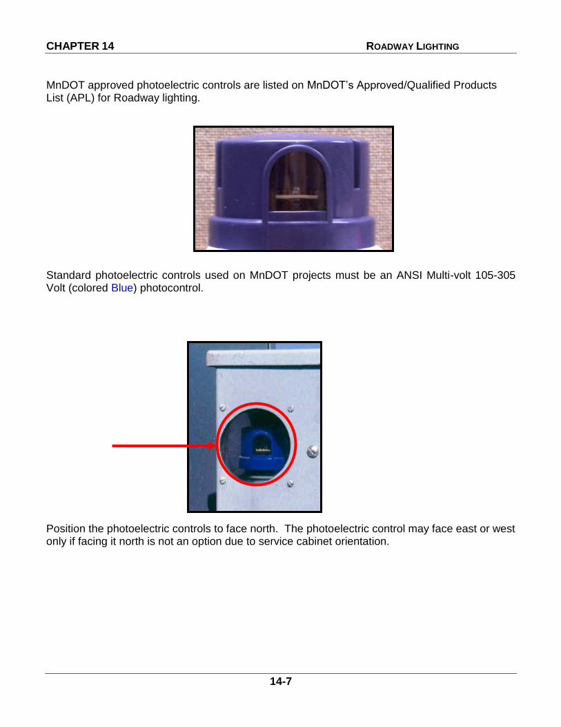
MnDOT approved photoelectric controls are listed on MnDOT’s Approved/Qualified Products List (APL) for Roadway lighting.
Standard photoelectric controls used on MnDOT projects must be an ANSI Multi-volt 105-305 Volt (colored Blue) photocontrol. Position the photoelectric controls to face north. The photoelectric control may face east or west only if facing it north is not an option due to service cabinet orientation.

CHAPTER 14 ROADWAY LIGHTING
14-8
DIRECT BURIED LIGHTING CABLE 3815 Most MnDOT lighting projects require direct buried 4 conductor No. 4 AWG cable. Direct buried lighting cable must be in accordance with contract documents. Within 15 days after the Contract approval notice mailing date, the Contractor must furnish evidence to the Engineer, in writing, that orders have been placed for all direct buried lighting cable required for the project.
WIRE AND CONDUCTOR INSTALLATION 2545.3 G Underground Wiring Direct Buried Lighting Cable Direct buried lighting cable must be installed in accordance with MnDOT 2545.3 G. The lighting cable must be installed at the same distance behind the bituminous shoulder or back of curb as the light foundations.

CHAPTER 14 ROADWAY LIGHTING
14-9
When an obstruction has been encountered in the path of the direct buried lighting cable, re-route the direct buried lighting cable around the obstruction away from the roadway. Direct buried lighting cable must be installed in rigid PVC or HDPE conduit under paved surfaces. Use a vibratory plow with a plow blade chute to reduce stresses on the cable during installation.
Place plastic warning tape meeting the following characteristics at least 12 inches (300 mm) above the direct buried lighting cable:
1. 3 inch (75 mm) wide, 2. Permanent Red 3. Stretchable 4. Non-biodegradable 5. Imprinted with the inscription, “CAUTION-MnDOT
LIGHTING CABLE BELOW” Install direct buried lighting cable from the reel or spool immediately into the ground. Do not lay direct buried lighting cable for the new lighting system on the ground and use as temporary.
2545.3G.2 Install direct buried lighting cable in rigid PVC or HDPE conduit if located under bituminous, concrete, or other material not considered a top soil. Provide 3 in conduit if the contract does not specify size of conduit.
CHAPTER 14 ROADWAY LIGHTING
14-10
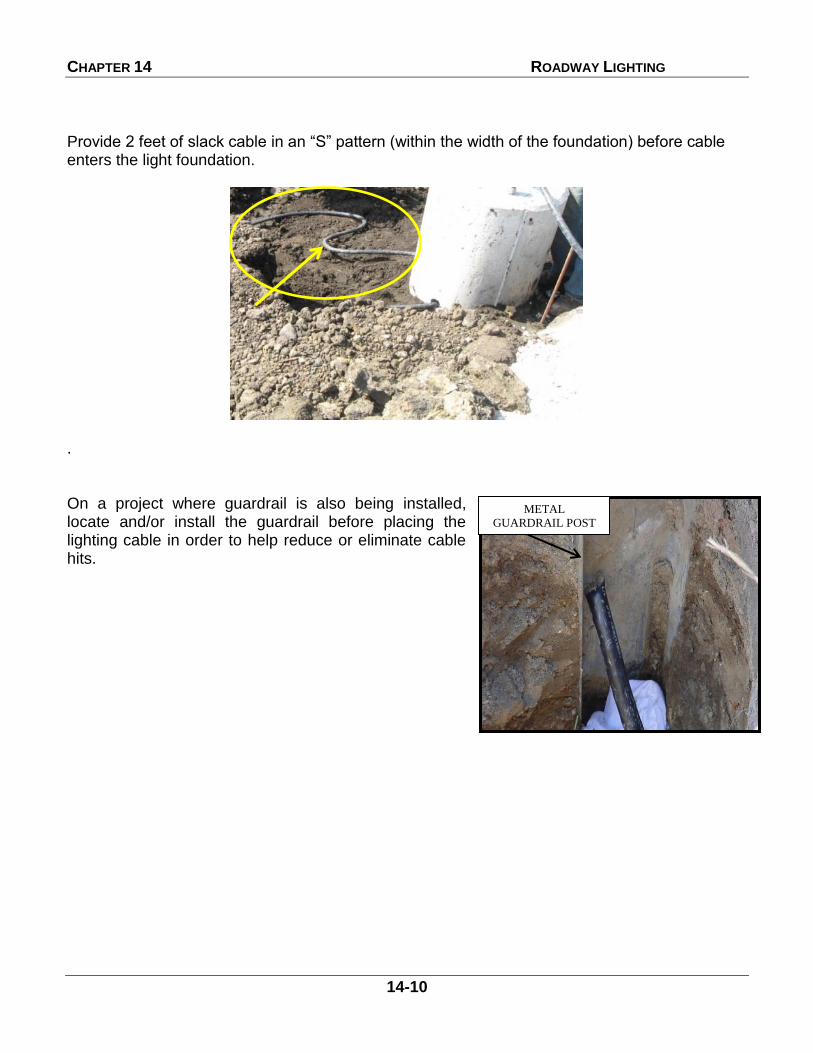
Provide 2 feet of slack cable in an “S” pattern (within the width of the foundation) before cable enters the light foundation.
. On a project where guardrail is also being installed, locate and/or install the guardrail before placing the lighting cable in order to help reduce or eliminate cable hits.
METAL
GUARDRAIL POST
CHAPTER 14 ROADWAY LIGHTING
14-11
Above Ground Splices
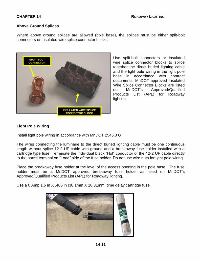
Where above ground splices are allowed (pole base), the splices must be either split-bolt connectors or insulated wire splice connector blocks.
Use split-bolt connectors or insulated wire splice connector blocks to splice together the direct buried lighting cable and the light pole wiring in the light pole base in accordance with contract documents. MnDOT approved Insulated Wire Splice Connector Blocks are listed on MnDOT’s Approved/Qualified Products List (APL) for Roadway lighting.
Light Pole Wiring Install light pole wiring in accordance with MnDOT 2545.3 G The wires connecting the luminaire to the direct buried lighting cable must be one continuous length without splice 12-2 UF cable with ground and a breakaway fuse holder installed with a cartridge type fuse. Terminate the individual black “Hot” conductor of the 12-2 UF cable directly to the barrel terminal on “Load” side of the fuse holder. Do not use wire nuts for light pole wiring. Place the breakaway fuse holder at the level of the access opening in the pole base. The fuse holder must be a MnDOT approved breakaway fuse holder as listed on MnDOT’s Approved/Qualified Products List (APL) for Roadway lighting. Use a 6 Amp 1.5 in X .406 in [38.1mm X 10.31mm] time delay cartridge fuse.
SPLIT-BOLT CONNECTOR
INSULATED WIRE SPLICE CONNECTOR BLOCK

CHAPTER 14 ROADWAY LIGHTING
14-12
The Contractor must provide sufficient excess conductor length to allow withdrawal of the connected fuse holder. The fuse holder must be properly orientated with respect to the line side and the load side. The neutral and grounding wires must not be fused.
Provide a MnDOT approved luminaire wire holder that supports the luminaire cable/conductors within the end of the light pole tenon near the connection point of the luminaire. MnDOT approved Wire Holders are listed on the MnDOT Approved/Qualified Products List (APL) for Roadway lighting.
Luminaire Wire Holders
LOAD SIDE
(Luminaire) LINE SIDE
(Supply Side)
CHAPTER 14 ROADWAY LIGHTING
14-13
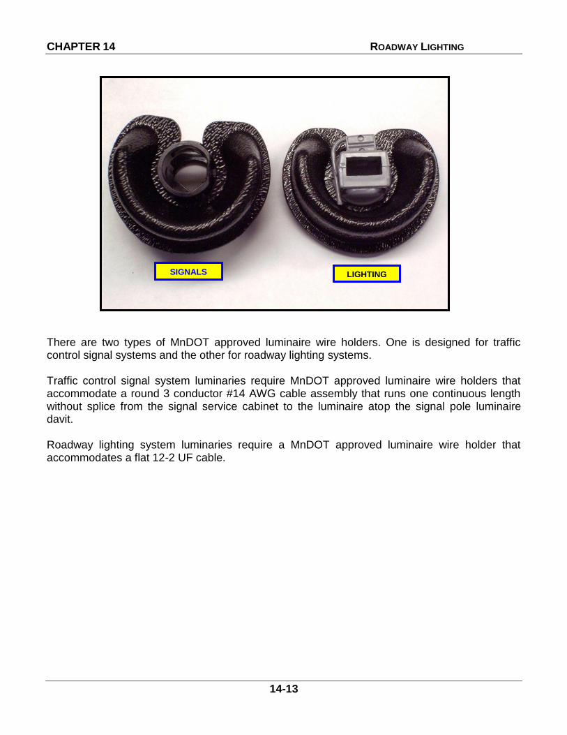
There are two types of MnDOT approved luminaire wire holders. One is designed for traffic control signal systems and the other for roadway lighting systems. Traffic control signal system luminaries require MnDOT approved luminaire wire holders that accommodate a round 3 conductor #14 AWG cable assembly that runs one continuous length without splice from the signal service cabinet to the luminaire atop the signal pole luminaire davit. Roadway lighting system luminaries require a MnDOT approved luminaire wire holder that accommodates a flat 12-2 UF cable.
SIGNALS LIGHTING

CHAPTER 14 ROADWAY LIGHTING
14-14
Underground Cable Splices No underground splices will be permitted that are not called for in the contract or approved in writing by the District Traffic Engineer. When direct buried cable splices are permitted install in accordance with 2545.3G.4.b.
Two Way Direct Buried Handhole Cable Splice When required, use a two way direct buried handhole cable splice in accordance with contract documents

CHAPTER 14 ROADWAY LIGHTING
14-15
Three Way Direct Buried Handhole Cable Splice
When required use a three way direct buried handhole cable splice in accordance with contract documents.
ROADWAY LIGHT POLES - 3811 General MnDOT roadway light poles:
1) Must be in accordance with the current edition of AASHTO Standard Specifications of Structural Supports for Highway Signs, Luminaires, and Traffic Signals.
2) If providing breakaway poles, the poles must be certified from the manufacturer that the pole meets specifications as specified in the current edition of AASHTO Standard Specifications of Structural Supports for Highway Signs, Luminaires, and Traffic Signals.
3) Must have a nominal 2 3/8 in schedule 40 tenon for slip fit luminaire installation. 4) Davit or mast arm must have an upward angle from horizontal of 3 degree +/- 2 degrees.
There are several of types of light poles MnDOT uses. The most common types of poles used on MnDOT roadway lighting systems are:
Coated (Galvanized) Steel Bridge and Barrier 40 foot and 49 foot nominal height Non-Breakaway
Stainless Steel 40 Foot and 49 Foot Breakaway Aluminum Alloy 40 Foot and 49 Foot Breakaway High Mast Light Towers

CHAPTER 14 ROADWAY LIGHTING
14-16
Bridge and Barrier Poles 40 Foot and 49 Foot
Galvanized Steel
Non-Breakaway
High Base
6-Bolt Base Plate
2 Access Door Assembly
Single and Double Davit
Mounted on Barrier (Center Median and Bridge Barrier Foundations)

CHAPTER 14 ROADWAY LIGHTING
14-17
Breakaway Roadway Light Poles 40 Foot and 49 Foot (Stainless Steel and Aluminum Alloy)
Aluminum Alloy Pole:
Transformer Base (Bolt On)
Typically Single Davit (6 FT- 12 FT)
Mounts on Design E and H Foundations
Stainless Steel Pole:
Slip Fit High Base
16 Sided
Typically Single Davit (6 FT – 12 FT)
Mounts on Design E and H
Foundations

CHAPTER 14 ROADWAY LIGHTING
14-18
High Mast Towers
COR-TEN Steel (Weathering Steel)
H Base Design
Typically 100 FT or 120 FT
Typically Ring Assembly Holds 3 to 4 Luminaires

CHAPTER 14 ROADWAY LIGHTING
14-19
A lighting unit is defined as follows: Includes the light pole, internal wiring with fuse holder and fuse to the luminaire, above ground splices, wire holder, stainless steel woven wire cloth, and luminaire. Underpass luminaires are lighting units even though they do not include some of these components. The foundation is not considered as part of this definition. The type of light pole required for each project will be shown in contract documents. Light poles that are specified by MnDOT are fabricated from stainless steel, high strength steel, or aluminum. Light poles fabricated from aluminum must have a factory installed vibration dampener. Light poles must be fabricated in accordance with MnDOT 3811. Within 15 days after the contract approval notice mailing date, the contractor must furnish evidence to the Engineer, in writing, that orders have been placed for all components of the lighting units required for the project. The Contractor must submit to the Engineer, for approval by the District’s Traffic Engineer, four complete sets of shop detail drawings of the light poles and anchor rods, in accordance with 2471.3B1 and 2471.3B3. For high mast lighting installations, the Contractor must submit final reproducible drawings in accordance with 2471.3B. The drawings must be distributed after approval, to the following:
(a) Contractor (b) Contractor’s Fabricator (c) Engineer (d) District Traffic Engineer
All light poles must be approved before installation.
LIGHT POLE INSTALLATION 2545.3 H Follow the light pole installation requirements in accordance with MnDOT 2545.3 H. Steel and stainless steel lights poles, and high mast light towers are fastened to the foundation anchorages using a top nut and a leveling nut with flat washers called a “double-nut moment connection”. This connection essentially clamps the pole base plate with the required flat washers in position between the top nut and the leveling nut. Both the top nut and leveling nut must be tightened with a wrench.

CHAPTER 14 ROADWAY LIGHTING
14-20
Aluminum light poles use a single nut connection or a heavy hex top nut to fasten the pole base to each foundation anchorage. In this connection the pole base rests directly on top of the foundation. Bridge and Barrier Galvanized Steel Light Poles with 6 Anchor Bolts
Typically galvanized steel light poles are installed on bridges and barrier with 6 anchor bolts. Light poles mounted on bridges and barrier are non-breakaway. Ensure the clearance between the bottom of the leveling nut and the top of foundation or “standoff distance” is less than one bolt diameter. Bridge and barrier mounted poles require two heavy hex jam nuts in place of one standard heavy hex nut for top nuts only. Do not use jam nuts in place of leveling heavy hex nuts. Heavy hex jam nuts are thinner than a standard heavy hex nut but have the same dimensions across the flats and corners. 2 heavy hex jam nuts = 1 standard heavy hex nut. Refer to Standard Plate 8332 for more information. Information on bridge and barrier mount pole foundations can be found in Chapter 10 Foundations & Equipment Pads.
2- JAM NUTS
2- FLAT WASHERS
LEVELING HEAVY HEX NUT
CHAPTER 14 ROADWAY LIGHTING
14-21
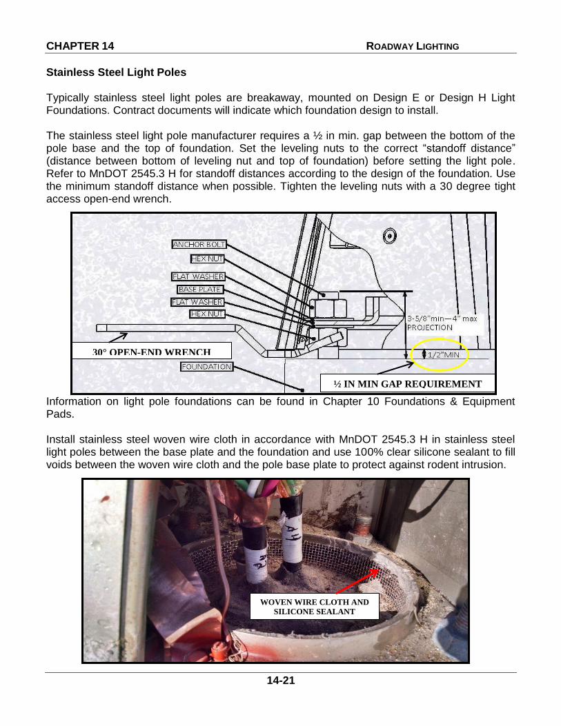
Stainless Steel Light Poles Typically stainless steel light poles are breakaway, mounted on Design E or Design H Light Foundations. Contract documents will indicate which foundation design to install. The stainless steel light pole manufacturer requires a ½ in min. gap between the bottom of the pole base and the top of foundation. Set the leveling nuts to the correct “standoff distance” (distance between bottom of leveling nut and top of foundation) before setting the light pole. Refer to MnDOT 2545.3 H for standoff distances according to the design of the foundation. Use the minimum standoff distance when possible. Tighten the leveling nuts with a 30 degree tight access open-end wrench. Information on light pole foundations can be found in Chapter 10 Foundations & Equipment Pads. Install stainless steel woven wire cloth in accordance with MnDOT 2545.3 H in stainless steel light poles between the base plate and the foundation and use 100% clear silicone sealant to fill voids between the woven wire cloth and the pole base plate to protect against rodent intrusion.
30° OPEN-END WRENCH
½ IN MIN GAP REQUIREMENT
WOVEN WIRE CLOTH AND
SILICONE SEALANT

CHAPTER 14 ROADWAY LIGHTING
14-22
Aluminum Light Poles
Typically aluminum light poles are breakaway, mounted on Design E or Design H Light Foundations. Contract documents will indicate which foundation design to install. If leveling is required install aluminum light poles with leveling shims (not leveling nuts). See Standard Plate 8129 for leveling shim requirements. Install holddown ½ in thick washers supplied with the aluminum light pole base with top nuts in accordance with MnDOT 2545.3 H. Do not use standard flat washers under the top nuts. For aluminum light pole bases do not install stainless steel woven wire cloth. Instead, fill any gaps as a result of using leveling shims that exceed 1/8 in between the foundation and the aluminum light pole base with 100% clear silicone sealant. Do not completely seal around the perimeter between the foundation and the aluminum light pole base.
USE ½ IN THICK HOLDDOWN WASHERS
LEVELING SHIMS

CHAPTER 14 ROADWAY LIGHTING
14-23
High Mast Lighting Towers Install high mast lighting towers and tower foundations in accordance with contract documents. Ensure the clearance between the bottom of the tower base plate and the top of foundation is 3 in. If leveling is required turn the leveling nuts that need adjustment downward towards the foundation.
Install stainless steel woven wire cloth in tower lighting base between the base plate and the foundation and use 100% clear silicone sealant to fill voids between the woven wire cloth and the tower base plate to protect against rodent intrusion.
WOVEN WIRE CLOTH AND
SILICONESEALANT

CHAPTER 14 ROADWAY LIGHTING
14-24
LUMINAIRES
All LED Luminaires listed on MnDOT’s APL have a minimum Ten (10) year warranty. These luminaires will operate in a range of 120 - 277 VAC (rms) with an integral power supply, pre-wired in the factory with terminal blocks or color coded pigtails for field connections. All MnDOT approved luminaires must have an ANSI C136.41-2013 standard 7-terminal twist-lock type photoelectric control mounting receptacle with shorting cap and a dimmable electronic driver (power supply). MnDOT approved luminaires are listed on MnDOT’s Approved/Qualified Products List (APL) for Roadway lighting. LED Roadway Luminaires (40 foot mounting height) Light emitting diode (LED) luminaires for mounting at 40 feet are replacements for the existing 250 watt HPS luminaire. The housing must be adaptable to the nominal 2 3/8 inch (50 mm) diameter tenon on the end of the luminaire mast arm. This class of LED luminaire is used in both roadway lighting and at traffic control signal systems. LED Roadway Luminaires (49 foot mounting height) Light emitting diode (LED) luminaires for mounting at 49 feet are replacements for the existing 400 watt HPS luminaire. The housing must be adaptable to the nominal 2 3/8 inch (50 mm) diameter tenon on the end of the luminaire mast arm.

CHAPTER 14 ROADWAY LIGHTING
14-25
Vertical Mount Luminaires LED Replacements (Replaces 250 and 400 HPS Luminaires) LED replacements for vertical mount luminaires are LED roadway luminaires for mounting at 49 feet. A 90 degree tenon mount adaptor must also be used. The 90 degree pole adaptor must be MnDOT approved adaptors listed on MnDOT’s Approved /Qualified Products List (APL) for Roadway lighting. LED Underpass Luminaires LED underpass luminaires are replacements for 250 watt high pressure sodium luminaires. The housing of the luminaire is anodized aluminum. Underpass luminaires are usually installed on the abutment of a bridge or on a pier a minimum of 17 feet above the traveled roadway. If such mounting would place a luminaire more than about 20 feet from the edge of the traveled roadway, the luminaire is usually mounted on a metal mounting bracket bolted under the bridge deck. Bird spikes are now required to be installed on underpass luminaires. A full size instruction sheet can be found in the appendix.

CHAPTER 14 ROADWAY LIGHTING
14-26
LED Luminaires on Signal Poles (40 foot mounting height)
Luminaires are mounted on signal poles to provide intersection illumination. They are LED luminaires found on MnDOT’s APL under LED Roadway Luminaires for mounting at 40 feet.
High Mast Luminaires (Tower Lights) High mast luminaires are 1000 watt high pressure sodium symmetrical or asymmetrical luminaires with ballasts. High mast luminaires must be MnDOT approved luminaires as listed on MnDOT’s Approved/Qualified Products List (APL) for Roadway lighting.

CHAPTER 14 ROADWAY LIGHTING
14-27
LUMINAIRE INSTALLATION 2545.3 Q Install and level luminaires in accordance with MnDOT 2545.3Q, the manufacturer’s installation requirements and to the satisfaction of the Engineer. Luminaires need to be installed in accordance with manufacturer’s installation requirements. Tightening of the bolts that hold the luminaire on the tenon have specific tightening torque requirements that must be followed. Over tightening of these bolts can cause damage to the luminaire or the tenon.

CHAPTER 14 ROADWAY LIGHTING
14-28
Place a level on the area provided on the top of the luminaire, and level side to side and front to back direction. Adjust the luminaire as required to completely level the luminaires. Luminaires must be level in order to perform properly. Lighting Controls Lighting controls (smart photocontrols) are becoming more popular with the introduction of the LED Luminaire. MnDOT Luminaires come standard with a 7 pin photocontrol receptacle with shorting cap and a dimmable electronic driver (power supply). These features make the luminaires lighting controls ready by simply replacing the shorting cap with a smart photocontrol.

CHAPTER 14 ROADWAY LIGHTING
14-29
On some MnDOT roadway lighting projects smart photocontrols may be required. The Department may supply the smart photocontrols to the contractor for installation on the luminaire prior to the luminaire being installed on the pole.
It’s important that the photocontrol window be faced north as required by the manufacturer. If a north facing node is not achievable then facing east or west is an acceptable alternative.
Lighting Control systems monitor and provide the following;
6. Energy measurement at revenue grade per luminaire 7. Luminaire voltage. 8. Luminaire wattage. 9. Luminaire type LED or HPS. 10. Luminaire dimming (0 to 10 Volts). 11. Dayburner. 12. No communication. 13. Global Positioning System (GPS) location.
No smart photocontrols are listed on the MnDOT APL for Lighting. There is a state contract in place where CPV members can purchase smart lighting controls. A modification in the lighting service cabinet will be required when lighting controls are installed. The contactor must be bypassed and de energized. Power to each luminaire will be on 24 hours a day. Continuous powering of the lighting control allows the lighting control and the luminaire to report their status 24 hours a day 7 days a week.
CHAPTER 14 ROADWAY LIGHTING
14-30
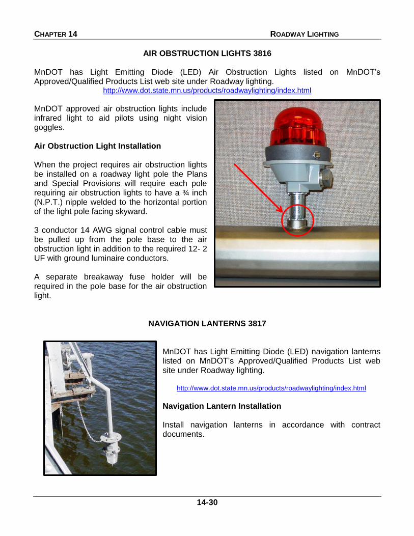
AIR OBSTRUCTION LIGHTS 3816 MnDOT has Light Emitting Diode (LED) Air Obstruction Lights listed on MnDOT’s Approved/Qualified Products List web site under Roadway lighting.
http://www.dot.state.mn.us/products/roadwaylighting/index.html
MnDOT approved air obstruction lights include infrared light to aid pilots using night vision goggles. Air Obstruction Light Installation When the project requires air obstruction lights be installed on a roadway light pole the Plans and Special Provisions will require each pole requiring air obstruction lights to have a ¾ inch (N.P.T.) nipple welded to the horizontal portion of the light pole facing skyward. 3 conductor 14 AWG signal control cable must be pulled up from the pole base to the air obstruction light in addition to the required 12- 2 UF with ground luminaire conductors. A separate breakaway fuse holder will be required in the pole base for the air obstruction light.
NAVIGATION LANTERNS 3817
MnDOT has Light Emitting Diode (LED) navigation lanterns listed on MnDOT’s Approved/Qualified Products List web site under Roadway lighting.
http://www.dot.state.mn.us/products/roadwaylighting/index.html
Navigation Lantern Installation Install navigation lanterns in accordance with contract documents.

CHAPTER 14 ROADWAY LIGHTING
14-31
LIGHT SYSTEM COMPONENT LABELING and NUMBERING 2545.3P
Lighting System Numbering The Contractor must number the light poles or the luminaires when light poles are not required (underpass luminaires, tunnel luminaires, special luminaires, etc.) and lighting service cabinets as specified in contract documents.
Lighting service cabinets must have two feed point labels 4 feet above the concrete foundation. One label is required on the front door and one on the side of the cabinet that faces the roadway. MnDOT approved labels are listed on MnDOT’s Approved/Qualified Products List (APL) for Roadway lighting.
FEEDPOINT NUMBER
POLE NUMBER
LIGHT POLE LIGHTING SERVICE CABINET
ASSETT TAG

CHAPTER 14 ROADWAY LIGHTING
14-32
Labeling Lighting Cable and Conductors Label the direct buried lighting cable in service cabinets and lights pole bases indicating the next termination point in accordance with MnDOT 2545.3 P.2.b.

CHAPTER 14 ROADWAY LIGHTING
14-33
Labeling Luminaires LED roadway luminaires require two types of labels be added by the contractor. One label defines the mounting height in feet 40 or 49 for the luminaire. The labels can be found on the MnDOT APL for lighting. Affix a machine printed label showing the month and year the LED luminaire was installed. Two of these labels are required, one on the outside of the luminaire facing the ground and one on the inside of the luminaire.
CONTRACTOR SUPPLIED The contractor may also be required to install luminaire asset tags. See contract documents if asset tags are required on the project. LED underpass luminaires do not require a mounting height label be applied however the installation date label and the light unit number are required.

CHAPTER 14 ROADWAY LIGHTING
14-34
ELECTRICAL SYSTEM TESTING AND ACCEPTANCE 2545.3K General testing and acceptance requirements must be in accordance with 2545.3K.
CHECKLIST FOR ELECTRICAL SYSTEMS *The following list is a minimum and does not replace applicable specifications in
The National Electrical Code (NEC) All Specification References are from the current Spec Book 1. Check SOP A. Meg all cables. Isolate neutral and ground. (2545.3K) B. All wires must meg greater than 100 meg ohms to earth ground. (2545.3K) C. All breakers labeled to indicate what poles are included in system per (NEC) D. Make sure wiring is neat. (2545.3G) E. Feedpoint number and “MnDOT ESS” labels should be on the cabinet.
(2545.3P) F. Available Fault Current Calculations and Cabinet Label. (2545.3A.1)
(2565.3CC) 2. Check Random Poles A. Check no less than 5 poles or up to one-third of system. B. Check fuse holder and fuse. (2545.3G3) C. Conduits right length. (Standard Plates 8127 and 8128) D. Splices insulated as per specs. (2545.3G4) E. Outside jacket of Direct Buried Lighting Cable striped back flush to 4 inches
above the conduit opening. (2545.3G2) F. Cable depth consistent no less than 24 inches direct buried and conduit depth
no less than 18 inches below finished grade. (2545.3G2) (2565.3D2b) G. Direct buried cable must be approximately 24 inches up into pole. (2545.3G.2) H. Handholes and lighting foundations to finish grade. (2545.3F2 and 2565.3E) I. Feed point and light poles’ numbers should be put on all poles. (2545.3P) J. Cable routing changes must be noted on prints. K. Check wiring diagram for accuracy. L. Poles and system must be effectively grounded. (2545.3R) M. Poles plumb and luminaires are level. (2545.3H and 2545.3Q) I certify that this project has met the above checklist criteria. Locating responsibility will be taken over when final is done and as-built is received.
________________________________________ ________________ (Name) (Date)

CHAPTER 14 ROADWAY LIGHTING
14-35
LIGHTING SYSTEM TESTING AND ACCEPTANCE Prior to completion of the work, the Contractor must test the entire system for unwanted grounds and conduct a 12 hour burn test for each feed point (2545 3K). Megohm meter test (Test for unwanted grounds) A megohm meter test, at 500 volts DC, indicating the insulation resistance of each circuit must be made. The Contractor must furnish the Engineer with a written report of the megohm meter readings for the permanent record. The report must contain the following information:
(1) PROJECT NUMBER AND LOCATION
(2) FEEDPOINT NUMBER - As indicated in the Plans.
(3) BRANCH CIRCUIT - Identify each lighting branch circuit being tested by indicating the number of the first light connected to that circuit, as indicated in the Plans.
(4) PHASE CONDUCTOR INSULATION RESISTANCE - Measure the resistance
between the phase conductors and between each phase conductor and the equipment ground bar in the service cabinet with the fuses removed from the in-line fuse connectors in the lighting poles. The resistance must not be less than 100 megohms.
(5) NEUTRAL CONDUCTOR INSULATION RESISTANCE - Measure the resistance
between each neutral conductor and the equipment ground bar in the service cabinet with the fuses removed from the in-line fuse connectors in the lighting poles. The resistance must not be less than 100 megohms.
(6) CIRCUIT INSULATION RESISTANCE - Measure the resistance between each phase
conductor and the equipment ground bar in the service cabinet with all fuses in place in the lighting poles. The resistance must not be less than 5 megohms.
The contractor must make sure that the two circuit conductors are connected to the circuit breaker of the opposite phases. All tests must be made at the service cabinet, in the presence of the Engineer, with all grounding connections in place. THE PHASE AND NEUTRAL CONDUCTORS MUST BE DISCONNECTED AT THE SERVICE CABINET FOR THE INSULATION RESISTANCE TESTS.

CHAPTER 14 ROADWAY LIGHTING
14-36
12 Hour Burn Test 2545.3K.2 Upon completion of a lighting system and before no more than 90% of the lighting system cost is paid, the lighting cabinet must be energized and the entire lighting system must operate successfully without interruption for 12 hours, during daylight hours only. The 12 hour burn test is conducted during daylight hours to ensure that the system is fully functional prior to it being placed into service. Where test results indicate faulty insulation or a faulty connection within the circuit, all necessary corrections must be made and the circuit retested, all at no expense to the Department. No additional payment will be made for replacing any part of or the entire circuit as required to make the circuits meet the test requirements.

CHAPTER 14 ROADWAY LIGHTING
14-37
LIGHTING STANDARD PLATES AND BRIDGE STANDARD FIGURES LIGHTING STANDARD PLATES: Equipment Pad B ..................................................................................... ........ 8106 Handholes ............................................................................................... ........ APL * Pulling Vaults ........................................................................................... ........ APL * Light Foundation–Design E ..................................................................... ........ 8127 Light Foundation - Design H .................................................................... ........ 8128 Shim And Washer .................................................................................... ........ 8129 Roadway Lighting Service Cabinets ........................................................ ........ APL * Reinforced Concrete Median Type F (Non-Glare Screen Type) ............. ........ 8308 LIGHT POLE FOUNDATION
Reinforced Concrete Median Type F and Glare Screen ......................... ........ 8309 LIGHT POLE FOUNDATION
Anchor Bolt Cluster and Base Plate for Light Poles ................................. ........ 8332 * Approved/Qualified Products List (APL)
BRIDGE STANDARD FIGURES: Refer to http://www.dot.state.mn.us/bridge/ for current Bridge CADD Standards (Standard Figures).

CHAPTER 14 ROADWAY LIGHTING
14-38
This Page
Intentionally Left
Blank