robert juliat table des matieres - partirentournee juliat... · fax : 33 (0)3.44.26.90.79 ......
TRANSCRIPT
I TABLE DES M ATIERES
USER'S MANUAL
Updated: 02/99
copyright © R Juliat 1998
robert juliat Route de Beaumont F 60530 Fresnoy-en-Thelle tél. : 33 (0)3.44.26.51.89fax : 33 (0)3.44.26.90.79
USITT DMX 512 ACCORDEDW I R I N G D A T A
VERSION 1 - 02
M.U
TIL
. T
IVO
LI.G
B/P
M/A
.PR
OD
UIT
S

copyright © R Juliat 1998
2
1. PRESENTATION ............................................................................................... 4
1.1. INTRODUCTION TO THE TIVOLI CABINET ................................................ 4
1.2. MANUAL ORGANISATION............................................................................. 4
1.3. LOGIC OF THE SYSTEM .............................................................................. 5
1.4. START MENU ................................................................................................. 6
2. BASIC MENU .................................................................................................... 7
2.1. LEVELS ......................................................................................................... 10
2.2. CONFIGURATION ........................................................................................ 11
2.3. CHANNEL TEST ........................................................................................... 13
2.4. PREFERENCES............................................................................................ 13
2.5. INFORMATION ............................................................................................. 14
2.6. SOFTWARE RESET ..................................................................................... 15
2.7. FURTHER DETAILS ..................................................................................... 16
3. DIGI TYPE MENU ........................................................................................... 17
3.1. LEVELS ......................................................................................................... 17
3.2. CHANNELS ................................................................................................... 17
3.3. CURVES........................................................................................................ 18
3.4. LOCAL CONTROL ........................................................................................ 18
3.5. RENAME ....................................................................................................... 19
3.6. STAGE (CONFIG.)........................................................................................ 19
3.7. CHANNEL TEST ........................................................................................... 19
3.8. PREFERENCES............................................................................................ 20
3.9. INFORMATION ............................................................................................. 20
copyright © R Juliat 1998
3
4. THE FULL MENU............................................................................................ 21
4.1. LEVELS ......................................................................................................... 21
4.2. CONFIGURATION ........................................................................................ 21
4.3. CHANNEL TEST ........................................................................................... 23
4.4. SHOW ........................................................................................................... 23
4.4.1. MEMORIES ................................................................................................ 24
4.4.2. CROSSFADES ........................................................................................... 25
4.4.3. SHOW EXECUTION .................................................................................. 27
4.4.4. SHOW PLUS MENU ................................................................................. 28
4.4.5. SHOW PARAMETERS .............................................................................. 28
4.4.6. MASTERS .................................................................................................. 29
4.4.7. INDEPENDENTLY-TIMED FADES............................................................ 29
4.4.8. EXTERNAL SWITCHES ............................................................................ 30
4.4.9. SHOW INFO .............................................................................................. 31
4.5. PREFERENCES............................................................................................ 32
4.5.1. CHANNEL PREFERENCES ...................................................................... 33
4.5.2. UNIT PREFERENCES ............................................................................... 34
4.6. TEST & INFO ............................................................................................... 35
4.7. SOFTWARE RESET ..................................................................................... 36
5. APPENDIX ....................................................................................................... 38
- Chart 256 steps DMX........................................................................................ 38
- Data wiring ......................................................................................................... 42
Note: This user’s manual is meant for TIVOLI program versions 1-01 -> 1-09.
copyright © R Juliat 1998
4
1. PRESENTATION
1.1. INTRODUCTION TO THE TIVOLI RACK
The TIVOLI rack is a completely digital dimmer unit, fitting up to 24 channels. It is the newcomer in therange of the ROBERT JULIAT digital dimmers.
TIVOLI checks the DMX 512 signal and rejects the data packets (or the end of data packets) whichcarry errors due to the transmission. When switching on the dimmer rack, and each time data is applied,TIVOLI analyses the protocol it receives before authorising the reception. Should the data link be cutoff, TIVOLI will retain the last valid data frame and hold that output.
TIVOLI also accepts analog 0/+10V and local controls. The output level is determined by the highestinput level, according to the dimmer curve and to the limitation imposed on each channel. The dimmercurve is the transposition of the input level to an output level following a specified lighting law. A 0 to100% limitation proportionally limits the dimmer output.
TIVOLI is designed for either single-phase or three-phase A.C. Voltage. The input frequency range is45.5Hz to 64Hz. A constant mains frequency is highly recommended. For further information on electricconnection and the output power of the channels, please refer to the technical data sheet.
TIVOLI can also be configured using a number of parameters; it can receive internal-sequence controlsand display information which facilitate optimum functioning. All these functions are performed by TIVOLIin addition to real time light control.
TIVOLI can work in “Automatic Mode”, meaning it can execute sequences programmed into the unit. Inthis manner, it will allow you to enter memories which will be played back through a local or externalcontrol. Versatility and working convenience are achieved through memories link - sequences andindependently-time fades.
A smoothing function improves dramatically the lighting yield by increasing the digital control resolutionfrom 256 steps to 7,500 steps through interpolation. The smoothing function is active by default.
1.2. ORGANISATION OF THIS MANUAL
The TIVOLI user’s manual is organised as follows: the first chapter (this one) is a general introductionto the cabinet (§1.1) with the description of the control panel - keys and LCD keyboard -, together withthe description of the start menu. Please read the whole chapter with care.
The 2nd chapter gives a detailed description of the basic menu and accessibility to the mentioned displays.It also explains the required key presses. If you are a beginner, this chapter is a must.
The 3rd chapter contains the differences between the DIGI IV/Vs displays and the Digi box type menu.You are a regular user of the DIGI IV/Vs dimmers, then you will start directly from this chapter.
The 4th chapter is addressed to the users who wish to give a personal touch to their cabinet. This chaptergives the description of the possibilities and parameters of TIVOLI.
For the best use of the different possibilities of TIVOLI, it is highly recommended to operate the unitwhile reading this manual.
copyright © R Juliat 1998
5
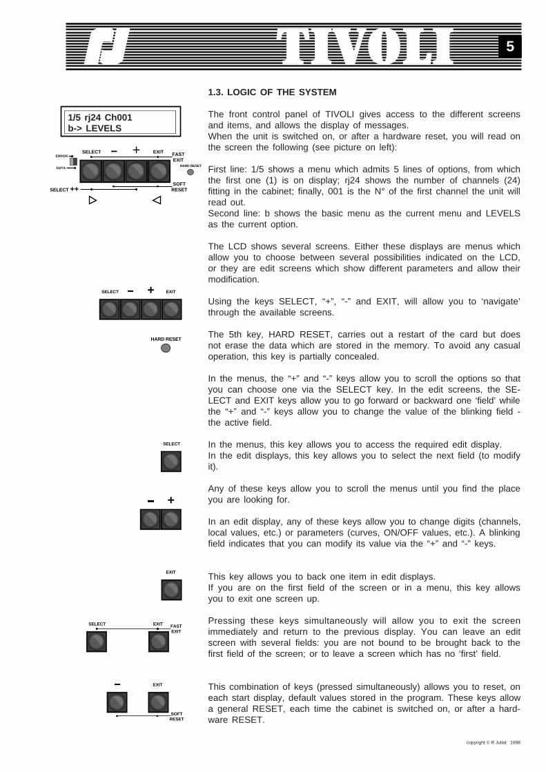
1.3. LOGIC OF THE SYSTEM
The front control panel of TIVOLI gives access to the different screensand items, and allows the display of messages.When the unit is switched on, or after a hardware reset, you will read onthe screen the following (see picture on left):
First line: 1/5 shows a menu which admits 5 lines of options, from whichthe first one (1) is on display; rj24 shows the number of channels (24)fitting in the cabinet; finally, 001 is the N° of the first channel the unit willread out.Second line: b shows the basic menu as the current menu and LEVELSas the current option.
The LCD shows several screens. Either these displays are menus whichallow you to choose between several possibilities indicated on the LCD,or they are edit screens which show different parameters and allow theirmodification.
Using the keys SELECT, “+”, “-” and EXIT, will allow you to ‘navigate’through the available screens.
The 5th key, HARD RESET, carries out a restart of the card but doesnot erase the data which are stored in the memory. To avoid any casualoperation, this key is partially concealed.
In the menus, the “+” and “-” keys allow you to scroll the options so thatyou can choose one via the SELECT key. In the edit screens, the SE-LECT and EXIT keys allow you to go forward or backward one ‘field’ whilethe “+” and “-” keys allow you to change the value of the blinking field -the active field.
In the menus, this key allows you to access the required edit display.In the edit displays, this key allows you to select the next field (to modifyit).
Any of these keys allow you to scroll the menus until you find the placeyou are looking for.
In an edit display, any of these keys allow you to change digits (channels,local values, etc.) or parameters (curves, ON/OFF values, etc.). A blinkingfield indicates that you can modify its value via the “+” and “-” keys.
This key allows you to back one item in edit displays.If you are on the first field of the screen or in a menu, this key allowsyou to exit one screen up.
Pressing these keys simultaneously will allow you to exit the screenimmediately and return to the previous display. You can leave an editscreen with several fields: you are not bound to be brought back to thefirst field of the screen; or to leave a screen which has no ‘first’ field.
This combination of keys (pressed simultaneously) allows you to reset, oneach start display, default values stored in the program. These keys allowa general RESET, each time the cabinet is switched on, or after a hard-ware RESET.
1/5 rj24 Ch001b-> LEVELS
SELECT
SELECT EXIT+
HARD RESET
ERROR
DATA
SELECT EXIT+HARD RESET
FASTEXIT
SOFTRESETSELECT ++
+
EXIT
SELECT EXIT FASTEXIT
EXIT
SOFTRESET

copyright © R Juliat 1998
6
From certain fields, this combination of keys (pressed simultaneously)allows you to access the extra display screens or edit screens.
1.4. THE START MENU
The cabinet is configurable to 3 operational modes, corresponding with 3start menus: the basic menu, the DIGI type menu and the full menu. Thebasic menu is the default menu, which can be maintained or you can canchange it for another menu of your choice. Each time the unit is switchedon, it will come back to the selected menu . On the second line of themenu, a lower-case letter - b, d or f - indicates the active menu.
The basic menu allows you access to the essential functions andparameters of the unit: display of the control levels for each channel, cir-cuit patching, flash test of the outputs at a 50% level, choice of thelanguage (french, english) and of the start menu, and, finally, display ofthe information concerning the data connection, mains frequency, programversion.
The DIGI type menu follows the menu of the DIGI IV/Vs units. The usersof Digi IV and Vs will recognize their customary interface. They will stickto it, if the new possibilities offered by the full menu are not enough toattract them.
The full menu allows full control of the cabinet parameters, with shortcutsand access to the most specific functions, such as programming andexecuting sequences.
The cabinet uses a single set of parameters to manage its operations.Indeed, the menu is only giving you access - large or small - to the vi-sualisation or the modification of the unparalleled parameters of this unit.For example, you give a channel a local level from the basic menu: thechannel will keep this level even after you have changed your type ofmenu. Similarly, resetting the curves in one of the menus bring the curvesback to their default values (Linear Light), which will be stored and usedfrom now on.
In the following chapters you will find the description of each level ofoperation, meaning each menu of the cabinet.
SELECT +
SELECT ++

copyright © R Juliat 1998
7
2. THE BASIC MENU.
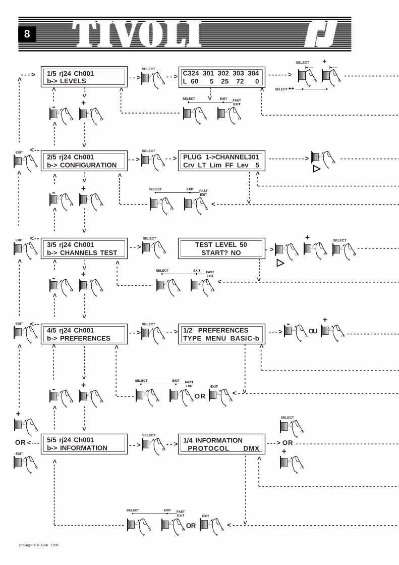
The basic menu bears 5 options, indicated by the digit blinking on top leftof the LCD. Each time a digital or alphanumeric ‘field’ is blinking, it showsthat you can modify its value via the “+” and “-” keys. In this manner youcan scroll the menu options. Once you have chosen an option, the SE-LECT key loads the corresponding edit screen.You will find below a summary of the screens to which you can accessfrom the basic menu. They will allow you to modify the basic parametersof the cabinet and to visualize the essential information. We will describethem in detail in the following paragraphs.
See next pages.
copyright © R Juliat 1998
8
1/5 rj24 Ch001b-> LEVELS
C324 301 302 303 304L 60 5 25 72 0
- - - - - - - - - - - - - - - - - - - - - - - - - - - - - - - - - - - - - -- - - - - - - - - - - - - - - - -
- - - ><
----
--
<------
<--2/5 rj24 Ch001b-> CONFIGURATION
- - > PLUG 1->CHANNEL301Crv LT Lim FF Lev 5
- - - - - - - - - - - >
- - - - - - > - - - - - - - - - - - - - - - -
- - - - - - - - - - - - - - - - -
3/5 rj24 Ch001b-> CHANNELS TEST
TEST LEVEL 50START? NO - > - - - - - - - - - - - -
<---
< - - - - - - - - - - - - - - - - - - - - - - - - - - - - - - - - - - - - - - - - - - - - - - - - - - -- - - - - - - -<
---
<--
----
---
<--
----
<------
<--
< - - - - - - - - - - - - - - - - - - - - - - - - - - - - - - - - - - - - - - - - - - - - - - - - - -- - - - - - - - - -
<--
----
<--
----
<------
<--
4/5 rj24 Ch001b-> PREFERENCES
1/2 PREFERENCESTYPE MENU BASIC-b
- - ->
- - - - -
<--
----
<------
<---------
- - - - - - - - - - - - - - - -
- - - - - - - - - - - - - - - - - - - - - - - - - - - - - - - - - - - - -
<--
<--
5/5 rj24 Ch001b-> INFORMATION
1/4 INFORMATION PROTOCOL DMX
- - ->
- - - - - - - - - - - - - - - - - - - - -
<-------------------
- - - - - - - - - - - - - - - - - - - - - - - - - - - - -
< - - - - - - - - - - - - - - - - - - - - - - - - - - - - - - - - - - - - - - - - - - - - - -
<---
< - - - - - - - - - - - - - - - - - - - - - - - - - - - - - - - - - - - - - - - - - -<--
----
----
--
<------
<------------
<--
----
---
<-
--
--
<---------
- - - - - - - - - - - - - - - - - - - - - - - - - - - - - - - - - - - - - - - -
<-------
OR
<----------------
<---------------
<--------------
<-------------------
<--
<--
<--
<-------
<------
<--
----
----
----
----
- - - - - - - - - - - - - - - - - - - - - - - - - - - - - - - - - - - - - - -
<---
SELECT EXIT FASTEXIT
SELECT ++
SELECT +
+
- +
- +
- +
-
SELECT
+
+
EXIT
EXIT
EXIT
EXIT
SELECT
SELECT
SELECT
SELECT
SELECT
SELECT EXIT FASTEXIT
SELECT EXIT FASTEXIT
SELECT EXIT FASTEXIT EXIT
SELECT EXIT FASTEXIT EXIT
SELECT
+
OU
+-
- - >
- - > - - >
- - >
- - > - - >
- - > - - >
OR
OR
OR

copyright © R Juliat 1998
9
PL24 1 2 3 4L 60 5 25 72 0
- - - - - - - - - - - - - - - -
Plug 1->CHANNEL301Num 3 Ana 5 Loc 10
- - - - - - - - >
- - - - - - - - - >
C311 312 313 314 315T 30 50 0 0 FF
- - - - - - - - >
- - - - - - - - - - - - - - - - - - - - - - - - - - - - - - - -
<--
-
<--
----
---
- - - - - - - - - - - - - - - - -
PL11 12 13 14 15T 30 50 0 0 FF
- - - - - - - - - - - > - - - - - - - - - - >
<--
-
2/2 PREFERENCES LANGUAGE ENGLISH
<--
--
- - - - - - - - - >
- - - - - - - - - -
2/4 INFORMATIONERRORS/1000PCK 0
- - - - - - - - >
- - - - - - - - - - - - - - - - - - - - - - - - - - - - - - - - - - - - - - - - - - - - - - - - - - - - - - - - - - - - - - - - - - - - - - - - - - - - - - - - - - - - - - - - - - - - - - - - - - - - - - -
- - - - - - - - - - - - - - - - - - - - - - - - - - - - - - - - <--
----
----
--
3/4 INFORMATION FREQUENCY 50.0Hz
- - ->- - -> 4/4 INFORMATION VERSION V1-01
<--
----
----
----
----
<--
--
- - - - - - - - - - -
<-------
- - - - - - - - - - - - - - - - - - - - -
<-------
- - - - - - - - - - - - - - - - - - -
<--
--
<------ - - - - - - - - - - - - - - - - - - - - - - - - - - - - - - - - - - - - - - - - - -
----
--
<--
----
----
----
----
<--
----
----
----
----
<--
---
- - - - - - - - - - - - -
----
< - - - - - - -
SELECT ++
SELECT +
-
OR
SELECT
+OR
SELECT
+
- -
SELECT ++
SELECT +SELECT ++
SELECT +
OR
+-
- - > - - >
copyright © R Juliat 1998
10
To go about the pages, you will simply follow the paths which are indicatedand press the suitable keys or combination of keys. Details concerning thefunctions and interest of these displays will be given further.
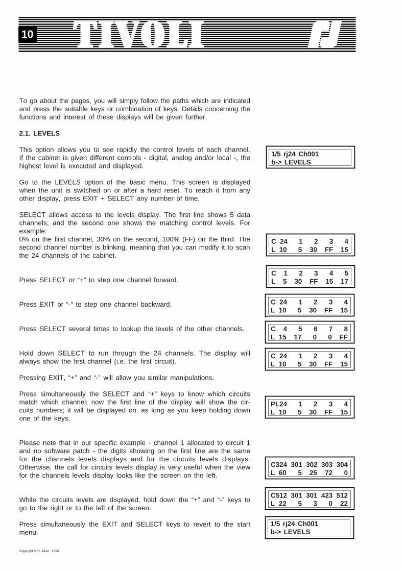
2.1. LEVELS
This option allows you to see rapidly the control levels of each channel.If the cabinet is given different controls - digital, analog and/or local -, thehighest level is executed and displayed.
Go to the LEVELS option of the basic menu. This screen is displayedwhen the unit is switched on or after a hard reset. To reach it from anyother display, press EXIT + SELECT any number of time.
SELECT allows access to the levels display. The first line shows 5 datachannels, and the second one shows the matching control levels. Forexample:0% on the first channel, 30% on the second, 100% (FF) on the third. Thesecond channel number is blinking, meaning that you can modify it to scanthe 24 channels of the cabinet.
Press SELECT or “+” to step one channel forward.
Press EXIT or “-” to step one channel backward.
Press SELECT several times to lookup the levels of the other channels.
Hold down SELECT to run through the 24 channels. The display willalways show the first channel (i.e. the first circuit).
Pressing EXIT, “+” and “-” will allow you similar manipulations.
Press simultaneously the SELECT and “+” keys to know which circuitsmatch which channel: now the first line of the display will show the cir-cuits numbers; it will be displayed on, as long as you keep holding downone of the keys.
Please note that in our specific example - channel 1 allocated to circuit 1and no software patch - the digits showing on the first line are the samefor the channels levels displays and for the circuits levels displays.Otherwise, the call for circuits levels display is very useful when the viewfor the channels levels display looks like the screen on the left.
While the circuits levels are displayed, hold down the “+” and “-” keys togo to the right or to the left of the screen.
Press simultaneously the EXIT and SELECT keys to revert to the startmenu.
1/5 rj24 Ch001b-> LEVELS
C 24 1 2 3 4L 10 5 30 FF 15
C 4 5 6 7 8L 15 17 0 0 FF
C 24 1 2 3 4L 10 5 30 FF 15
C 1 2 3 4 5L 5 30 FF 15 17
C 24 1 2 3 4L 10 5 30 FF 15
PL24 1 2 3 4L 10 5 30 FF 15
C324 301 302 303 304L 60 5 25 72 0
1/5 rj24 Ch001b-> LEVELS
C512 301 301 423 512L 22 5 3 0 22
copyright © R Juliat 1998
11
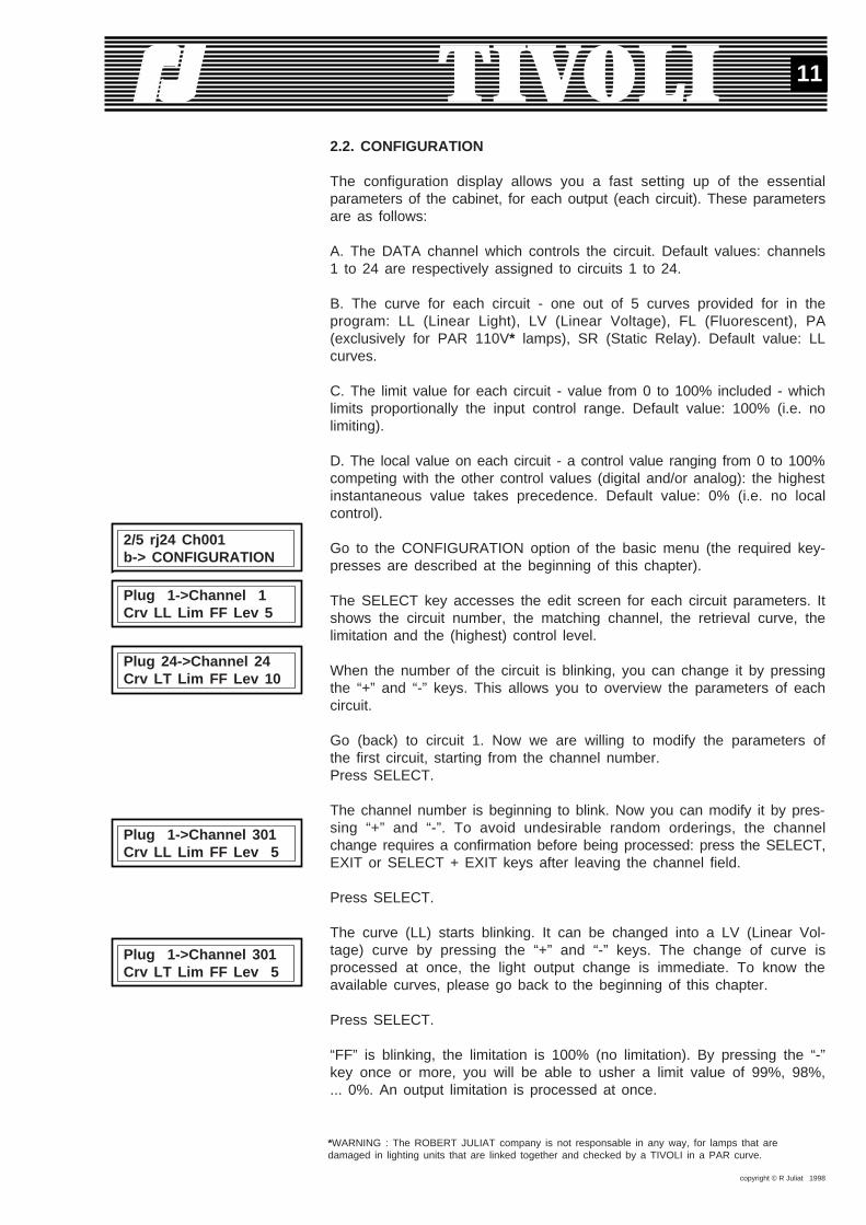
2.2. CONFIGURATION
The configuration display allows you a fast setting up of the essentialparameters of the cabinet, for each output (each circuit). These parametersare as follows:
A. The DATA channel which controls the circuit. Default values: channels1 to 24 are respectively assigned to circuits 1 to 24.
B. The curve for each circuit - one out of 5 curves provided for in theprogram: LL (Linear Light), LV (Linear Voltage), FL (Fluorescent), PA(exclusively for PAR 110V* lamps), SR (Static Relay). Default value: LLcurves.
C. The limit value for each circuit - value from 0 to 100% included - whichlimits proportionally the input control range. Default value: 100% (i.e. nolimiting).
D. The local value on each circuit - a control value ranging from 0 to 100%competing with the other control values (digital and/or analog): the highestinstantaneous value takes precedence. Default value: 0% (i.e. no localcontrol).
Go to the CONFIGURATION option of the basic menu (the required key-presses are described at the beginning of this chapter).
The SELECT key accesses the edit screen for each circuit parameters. Itshows the circuit number, the matching channel, the retrieval curve, thelimitation and the (highest) control level.
When the number of the circuit is blinking, you can change it by pressingthe “+” and “-” keys. This allows you to overview the parameters of eachcircuit.
Go (back) to circuit 1. Now we are willing to modify the parameters ofthe first circuit, starting from the channel number.Press SELECT.
The channel number is beginning to blink. Now you can modify it by pres-sing “+” and “-”. To avoid undesirable random orderings, the channelchange requires a confirmation before being processed: press the SELECT,EXIT or SELECT + EXIT keys after leaving the channel field.
Press SELECT.
The curve (LL) starts blinking. It can be changed into a LV (Linear Vol-tage) curve by pressing the “+” and “-” keys. The change of curve isprocessed at once, the light output change is immediate. To know theavailable curves, please go back to the beginning of this chapter.
Press SELECT.
“FF” is blinking, the limitation is 100% (no limitation). By pressing the “-”key once or more, you will be able to usher a limit value of 99%, 98%,... 0%. An output limitation is processed at once.
*WARNING : The ROBERT JULIAT company is not responsable in any way, for lamps that aredamaged in lighting units that are linked together and checked by a TIVOLI in a PAR curve.
2/5 rj24 Ch001b-> CONFIGURATION
Plug 1->Channel 1Crv LL Lim FF Lev 5
Plug 24->Channel 24Crv LT Lim FF Lev 10
Plug 1->Channel 301Crv LL Lim FF Lev 5
Plug 1->Channel 301Crv LT Lim FF Lev 5

copyright © R Juliat 1998
12
Press “-” 5 times.You have set up a 95% limitation on circuit 1.
Press “+” 2 times.You have modified this limitation to 97%.
Press SELECT.
The second line of the mask has changed. It shows the three control va-lues - Digital, Analog and Local - received by the circuit. It is possible tomodify the local value on the unit itself, without a control desk.
Press the “+” and “-” keys to bring circuit 1 to the local level: 10%. Themodification is processed at once. Should the local level be highest amongany other control (digital, analog) of the circuit, the light output will follow it.
All parameters of circuit 1 have been modified as intended. Now we shallproceed to the second circuit. Press the EXIT key 2 times or SELECTonce to return to the circuit field.Press SELECT.
The circuit number is blinking, press the “+” key to go to the second cir-cuit. Now you can modify the parameters of circuit 2, proceeding the wayyou did previously on circuit 1. Except for one difference, the channelnumber is no more accessible to modifications; the first channel is the onewhich decides of the channel numbers dedicated to the remaining circuits.
Once you are initiated to the basic manipulations you are able to modifyeach circuit, either following the explanations above, or proceeding on eachparameter: for example, you can modify the curves, then some limitationsor part of the local values.
If the parameters values of the circuits differ from their default values, asignalling character will appear on the right of the first line of the menu.For instance:- a lower-case “c” signals that at least one circuit has a different curvefrom the LL (Linear Light) one, while if this letter does not show it meansall the curves are “LL”;
- a lower-case “m” signals at least one limitation, while if this letter doesnot show it means no limitation;
- a lower-case “l” signals at least one local value, while if this letter doesnot show it means that all the local values are 0.
As for the previous modifications, the menu has become:
All the parameters modifications are automatically saved and stored, evenwhen there is a power cut.
Plug 1->Channel 301Crv LT Lim 97 Lev 5
Plug 1->Channel 301Num 3 Ana 5 Loc 0
Plug 1->Channel 301Num 3 Ana 5 Loc 10
2/5 rj24 Ch301 cb-> CONFIGURATION
2/5 rj24 Ch301 mb-> CONFIGURATION
2/5 rj24 Ch301 clmb-> CONFIGURATION
Plug 2->Channel 302Crv LL Lim FF Lev 25
Plug 3->Channel 303Crv LL Lim FF Lev 72
2/5 rj24 Ch301 lb-> CONFIGURATION
Plug 1->Channel 301Crv LT Lim 95 Lev 5

copyright © R Juliat 1998
13
2.3. CHANNELS TEST
TIVOLI allows the testing of each channel to a chosen level; the defaulttest value is 50%. Accordingly, the output value will match the restitutioncurve and the limitation for the tested channel.
Go to the CHANNELS TEST option of the basic menu (the required ma-nipulations are described at the beginning of this chapter).
The SELECT key accesses the start test display. This screen allows youto select the test value. It is also acting as a protection from manipulationerrors: to carry out the test, first you have to answer YES to the question«START?”.
Press the “+” or “-” keys to modify the test value. The new level willsupersede the default 50% value and will be kept as test value.Press SELECT to access the next field.
Press the “+” or “-” keys if you wish to start the test.
Press SELECT.You have just entered the test display. It looks like the LEVEL screen andit actually shows the control levels for the 5 displayed channels. As forthe current channel, blinking, the displayed output value which is displayedis the highest among the existing controls input - digital, analog - and thetest control. On the other hand, during the test, the local control of thecurrent channel is momentarily suppressed; it will be restored as soon asyou will leave the channel.
To test the other channels, press the “+” (or SELECT) and “-” (or EXIT)keys.
Press simultaneously the SELECT and “+” keys to display on the first linethe circuit numbers matching the channels being tested. The test per cir-cuit display is similar to the level per circuit screen.
Pressing the SELECT + EXIT keys will bring you back to the start menu.
2.4. PREFERENCES
Go to the option PREFERENCES in the basic menu (the required mani-pulations are described at the beginning of this chapter).
Press SELECT to access Preferences.You will be asked for the access code («password») which you previouslyset up in the full menu. It is important to remember this code and be ableto key it in upon request. Do not modify preferences without reason.
3/5 rj24 Ch301 clmb-> CHANNELS TEST
TEST LEVEL 90 START? NO
TEST LEVEL 90 START? YES
C311 312 313 314 315T 30 90 0 0 FF
C312 313 314 315 316T 50 90 0 FF 63
PL12 13 14 15 16T 50 90 0 FF 63
4/5 rj24 Ch301 clmb-> PREFERENCES
PASSWORD 1427
TEST LEVEL 50 START? NO
copyright © R Juliat 1998
14
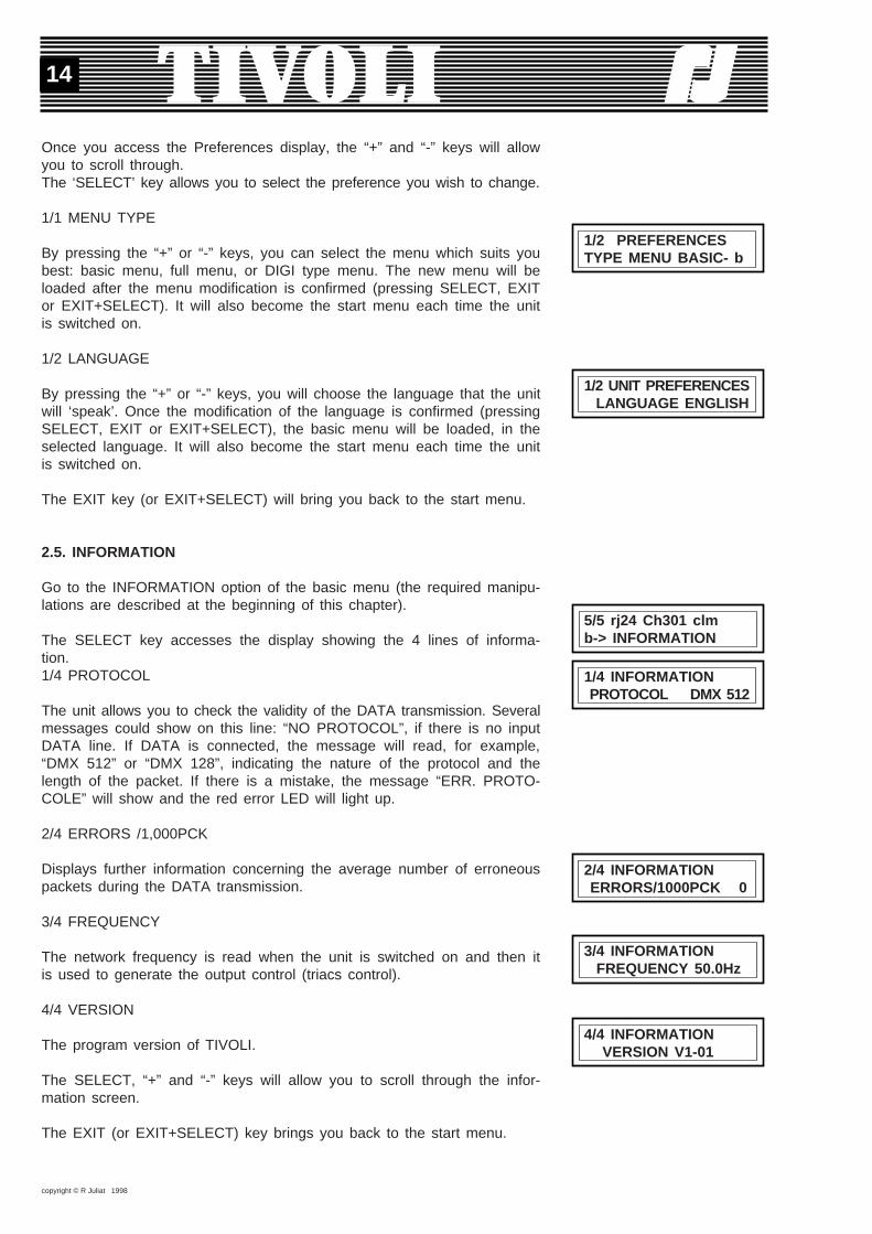
Once you access the Preferences display, the “+” and “-” keys will allowyou to scroll through.The ‘SELECT’ key allows you to select the preference you wish to change.
1/1 MENU TYPE
By pressing the “+” or “-” keys, you can select the menu which suits youbest: basic menu, full menu, or DIGI type menu. The new menu will beloaded after the menu modification is confirmed (pressing SELECT, EXITor EXIT+SELECT). It will also become the start menu each time the unitis switched on.
1/2 LANGUAGE
By pressing the “+” or “-” keys, you will choose the language that the unitwill ‘speak’. Once the modification of the language is confirmed (pressingSELECT, EXIT or EXIT+SELECT), the basic menu will be loaded, in theselected language. It will also become the start menu each time the unitis switched on.
The EXIT key (or EXIT+SELECT) will bring you back to the start menu.
2.5. INFORMATION
Go to the INFORMATION option of the basic menu (the required manipu-lations are described at the beginning of this chapter).
The SELECT key accesses the display showing the 4 lines of informa-tion.1/4 PROTOCOL
The unit allows you to check the validity of the DATA transmission. Severalmessages could show on this line: “NO PROTOCOL”, if there is no inputDATA line. If DATA is connected, the message will read, for example,“DMX 512” or “DMX 128”, indicating the nature of the protocol and thelength of the packet. If there is a mistake, the message “ERR. PROTO-COLE” will show and the red error LED will light up.
2/4 ERRORS /1,000PCK
Displays further information concerning the average number of erroneouspackets during the DATA transmission.
3/4 FREQUENCY
The network frequency is read when the unit is switched on and then itis used to generate the output control (triacs control).
4/4 VERSION
The program version of TIVOLI.
The SELECT, “+” and “-” keys will allow you to scroll through the infor-mation screen.
The EXIT (or EXIT+SELECT) key brings you back to the start menu.
1/2 PREFERENCESTYPE MENU BASIC- b
1/2 UNIT PREFERENCES LANGUAGE ENGLISH
5/5 rj24 Ch301 clmb-> INFORMATION
1/4 INFORMATION PROTOCOL DMX 512
2/4 INFORMATION ERRORS/1000PCK 0
3/4 INFORMATION FREQUENCY 50.0Hz
4/4 INFORMATION VERSION V1-01

copyright © R Juliat 1998
15
2.6. SOFTWARE RESET
Pressing simultaneously the EXIT and “-” keys will allow you to access tothe various software resets, on each line of the basic menu. If a passwordwas set up in the full menu, access to the resets depends on your knowingit. Finally, you will be asked to confirm the reset, which will be followedby a completion message.
The basic menu gives you 4 different resets.1. Levels Reset: clears local levels and, when there is no DATAconnection, it clears the digital levels (when the DATA connection is off,TIVOLI retains the last valid controls for the lighting outputs).2. Parameters Reset: the circuits parameters are given their default va-lues again (cf subchapter 2.2).3. Local Values Reset: clears the local levels and restores test level to50%.4. Preferences Reset: gives the following parameters the values as shownbelow.Soft start: ONBooster: OFFSmoothing: ONOvervoltage: 280VDisplay: DecimalAccess Code: 0
Go to the LEVEL option of the basic menu.
Press EXIT + “-” to start the levels reset.The confirmation mask will show.
Press EXIT or EXIT+SELECT to abort.Press SELECT to carry out the reset.
Press the EXIT key to return the start menu. The lower-case “l” is notshowing any more, all the local values are cleared out.
Go to the CONFIGURATION option of the basic menu.
Press EXIT + “-” to start the parameters reset; then follow the indicationsof the levels reset.
After confirmation of the reset and the menu is displaying again, the lower-case letters “c” and “m” are not showing any more, since the curves andlimitation are cleared; channel 1 is affected to circuit 1.
Go to the CHANNELS TEST option in the basic menu.Press EXIT + “-” to start the local values reset; then follow the indicationsof the levels reset.
Go to the PREFERENCES or INFORMATION options in the basic menu.
Press EXIT + “-” to start the preferences reset; then follow the indicationsof the levels reset.
1/5 rj24 Ch301 clmb-> LEVELS
PRESS SELECT 1sFOR LEVELS RESET
LEVELS RESET PERFORMED
1/5 rj24 Ch301 c mb-> LEVELS
2/5 rj24 Ch301 c mb-> CONFIGURATION
PRESS SELECT 1sFOR CONFIG. RESET
2/5 rj24 Ch001b-> CONFIGURATION
PRESS SELECT 1sFOR LOCAL RESET
PRESS SELECT 1sFOR PREFERENCE RESET

copyright © R Juliat 1998
16
A lower-case “f” will show on the first line of the menu, on the right, ifone of the preferences values has been changed from another menu. Thepreferences will return to their default levels - and the lower-case “f” willclear out - the moment the preferences reset is confirmed.
The general reset is the most powerful. It forces all the channel parametersto their default values, as well as the channels or the unit preferences,and it erases the presets, masters fields and crossfades for the show. Youmay access the general reset by holding together the EXIT and “-” keyswhile switching on the unit. If the unit is already on, just hold on theRESET HARDWARE key while pressing the EXIT and “-” keys.
After confirmation, the general reset deletes any parameters modificationsstored in the block and restores the default values.
To carry out a general reset, you will be asked a passcode (if you havepreviously entered a locking code).
2.7. FURTHER DETAILS
If the Voltage on one of the mains phases exceeds the blocking Voltage(280V by default), the output is blocked and a warning is displaying.The channels stay off, even if you leave this display: as a reminder, asmall black square will show on the first line of the menu. Find out thereason for the overvoltage, try and put it right, then restart the unit. Referto the full menu for additional details on the blocking voltage.Some parameters modifications carried out in the other menus may havean effect on the displays we have described previously (refer to the fullmenu: here we are only indicating the differences in the display or themanipulation).
A. On the first line of the menu, a lower-case “p” shows the patch is ON.The configuration display of the basic menu will allow you to modify thechannel numbers for each circuit.
B. If RENAME is ON, the displays of several screens in the basic menuwill look different.This is how the display per level screen will show:You will notice on the display that the level of the current circuit is blinking.
The CONFIGURATION screen will display as shown:
This display will allow you to modify, if you wish, the name of each cir-cuit in the same manner as you would modify the other circuits parameters.Eventually, the test per circuit screen displays as shown:
C. On the first line of the menu, a lower-case “f” shows on the right. Itsignals that one or more preferences of the list below differ from the defaultvalue. If no “f” is showing, the preferences have the default value indicatedhereafter:Soft start: ONBooster: OFFSmoothing: ONOvervoltage: 280VDisplay: DecimalAccess Code: 0
GENERAL RESET PERFORMED
PRESS SELECT 1sFOR GENERAL RESET
OVERVOLTAGE OUTPUT IS BLACK
1/5 rj24 Ch301 pb-> LEVELS
Ren8048->Pr 1->Ch301L 60 5 25 72 0
PL 1->Ren8048->Ch301Crv LT Lim 97 Lev 5
Ren8048->PL 1->Ch301T 60 90 25 72 0

copyright © R Juliat 1998
17
3. THE DIGI TYPE MENU
The DIGI type menu provides the users of the DIGI IV/Vs units with asequence of displays to which they grew accustomed. Nevertheless theinformation, which used to fit the LCD surface for a 6 channels dimmer,will take up several pages. As a consequence, a menu has taken the placeof the DIGI IV/Vs displays (channels, curves, local, etc.) which were theentry-points to the edit screens.
In the following sub-chapters we shall mention the displays or manipula-tions which differ from the DIGI IV/V screens you already know.
If you wish the Digi Box type menu as a start menu for the cabinet: goto the preferences in the other menus and change the type of the menu.
3.1. LEVELS
Entry-point: the DIGI menu, LEVELS option.
Levels per channel screen: the first line shows 5 channels of the unit, thematching levels show on the second line.
The SELECT key (one channel forward) and EXIT key (one channelbackward) will allow you access to the other channels.You will hold downthe SELECT (or EXIT) key to reach the first channel.Press simultaneously the SELECT and “+” keys to see the LEVELS percircuit screen: the first line shows the 5 circuits corresponding to thechannels previously displayed.
If the rename is ON, the screen displays differently.
Press the EXIT and SELECT keys to exit the levels display.
Press simultaneously the EXIT and “-” keys to perform a software resetof the local values and, in the case of no DATA connection, of the digitalcontrols (LEVELS RESET).
3.2. CHANNELS
Entry-point: the DIGI menu, CHANNELS option.
Channels patch screen: the first line shows 5 channels of the unit, thematching channels show on the second line. When the patch is OFF, youcan modify the channel affected to the first circuit; you can modify anychannel when the patch is ON. To avoid undesirable random output, thechannel change requires a confirmation before being processed: afterleaving the current field, press the SELECT, EXIT or SELECT+EXIT keys.
1/9 rj24 Ch301d-> LEVELS
C324 301 302 303 304L 60 5 25 72 0
PL24 1 2 3 4L 60 5 25 72 0
Ren8048->Pr 1->Ch301L 60 5 25 72 0
1/9 rj24 Ch301d-> LEVELS
PRESS SELECT 1sFOR LEVELS RESET
2/9 rj24 Ch301d-> CHANNELS
PL24 1 2 3 4C324 301 302 303 304
copyright © R Juliat 1998
18
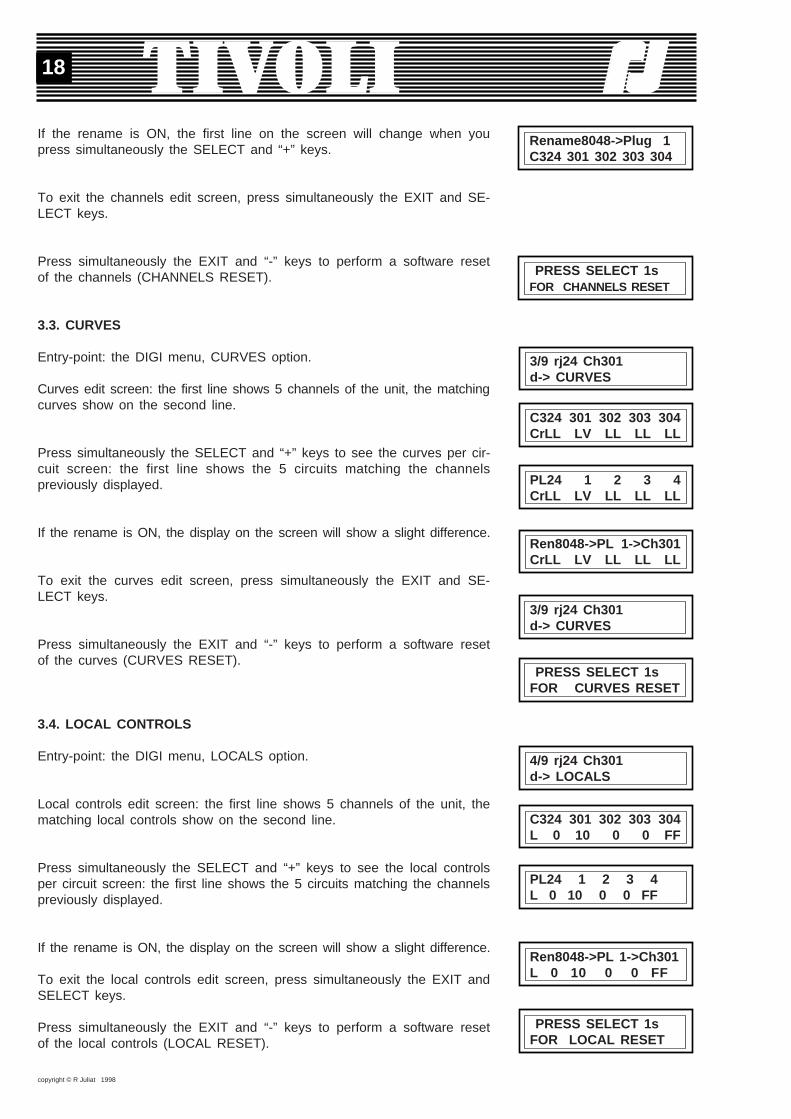
If the rename is ON, the first line on the screen will change when youpress simultaneously the SELECT and “+” keys.
To exit the channels edit screen, press simultaneously the EXIT and SE-LECT keys.
Press simultaneously the EXIT and “-” keys to perform a software resetof the channels (CHANNELS RESET).
3.3. CURVES
Entry-point: the DIGI menu, CURVES option.
Curves edit screen: the first line shows 5 channels of the unit, the matchingcurves show on the second line.
Press simultaneously the SELECT and “+” keys to see the curves per cir-cuit screen: the first line shows the 5 circuits matching the channelspreviously displayed.
If the rename is ON, the display on the screen will show a slight difference.
To exit the curves edit screen, press simultaneously the EXIT and SE-LECT keys.
Press simultaneously the EXIT and “-” keys to perform a software resetof the curves (CURVES RESET).
3.4. LOCAL CONTROLS
Entry-point: the DIGI menu, LOCALS option.
Local controls edit screen: the first line shows 5 channels of the unit, thematching local controls show on the second line.
Press simultaneously the SELECT and “+” keys to see the local controlsper circuit screen: the first line shows the 5 circuits matching the channelspreviously displayed.
If the rename is ON, the display on the screen will show a slight difference.
To exit the local controls edit screen, press simultaneously the EXIT andSELECT keys.
Press simultaneously the EXIT and “-” keys to perform a software resetof the local controls (LOCAL RESET).
C324 301 302 303 304CrLL LV LL LL LL
PL24 1 2 3 4CrLL LV LL LL LL
3/9 rj24 Ch301d-> CURVES
PRESS SELECT 1sFOR CURVES RESET
4/9 rj24 Ch301d-> LOCALS
C324 301 302 303 304L 0 10 0 0 FF
PL24 1 2 3 4L 0 10 0 0 FF
Ren8048->PL 1->Ch301L 0 10 0 0 FF
PRESS SELECT 1sFOR LOCAL RESET
Ren8048->PL 1->Ch301CrLL LV LL LL LL
3/9 rj24 Ch301d-> CURVES
PRESS SELECT 1sFOR CHANNELS RESET
Rename8048->Plug 1C324 301 302 303 304
copyright © R Juliat 1998
19
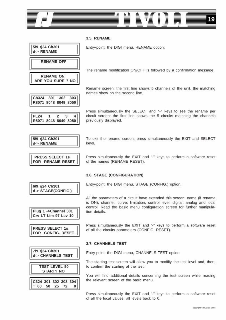
3.5. RENAME
Entry-point: the DIGI menu, RENAME option.
The rename modification ON/OFF is followed by a confirmation message.
Rename screen: the first line shows 5 channels of the unit, the matchingnames show on the second line.
Press simultaneously the SELECT and “+” keys to see the rename percircuit screen: the first line shows the 5 circuits matching the channelspreviously displayed.
To exit the rename screen, press simultaneously the EXIT and SELECTkeys.
Press simultaneously the EXIT and “-” keys to perform a software resetof the names (RENAME RESET).
3.6. STAGE (CONFIGURATION)
Entry-point: the DIGI menu, STAGE (CONFIG.) option.
All the parameters of a circuit have extended this screen: name (if renameis ON), channel, curve, limitation, control level, digital, analog and localcontrol. Read the basic menu configuration screen for further manipula-tion details.
Press simultaneously the EXIT and “-” keys to perform a software resetof all the circuits parameters (CONFIG. RESET).
3.7. CHANNELS TEST
Entry-point: the DIGI menu, CHANNELS TEST option.
The starting test screen will allow you to modifiy the test level and, then,to confirm the starting of the test.
You will find additional details concerning the test screen while readingthe relevant screen of the basic menu.
Press simultaneously the EXIT and “-” keys to perform a software resetof all the local values: all levels back to 0.
5/9 rj24 Ch301d-> RENAME
RENAME OFF
RENAME ON ARE YOU SURE ? NO
Ch324 301 302 303R8071 8048 8049 8050
PL24 1 2 3 4R8071 8048 8049 8050
5/9 rj24 Ch301d-> RENAME
PRESS SELECT 1sFOR RENAME RESET
6/9 rj24 Ch301d-> STAGE(CONFIG.)
Plug 1 ->Channel 301Crv LT Lim 97 Lev 10
PRESS SELECT 1sFOR CONFIG. RESET
7/9 rj24 Ch301d-> CHANNELS TEST
TEST LEVEL 50 START? NO
C324 301 302 303 304T 60 50 25 72 0

copyright © R Juliat 1998
20
3.8. PREFERENCES
Entry-point: the DIGI menu, PREFERENCES option.
You will acknowledge the preferences: start software, patch, booster,smoothing, decimal/hex display, access code, language. A new preference:TIVOLI allows you to choose from 3 menus.
A lower-case “p” will show on the first line of the menu if the patch isON.
Also, it will display the values of the other 6 preferences; their default va-lues are the followings:Soft start: ONBooster: OFFSmoothing: ONOver voltage (accessible from the full menu): 280VDisplay: DecimalAccess Code: 0
A lower-case“f” will show on the first line of the menu as soon as one ofthe 5 accessible preferences is ascribed a value which differs from thedefault value.
As for the default values of the last two preferences, they are as follows:Language: no default value.Menu type: basic menu.
Press simultaneously the EXIT and “-” keys to perform a software resetof all the preferences (PREFERENCES RESET). All the preferences,except the menu type, will be forced back to their default values.
3.9. INFORMATION
Entry-point: the DIGI menu, INFORMATION option.
One additional information concerns the mains frequency. When the unitis switched on, it reads this information and then uses it to generate theoutput controls (triacs control).
Press simultaneously the EXIT and “-” keys to perform a software resetof all the preferences.
If the voltage on one of the mains phases overflows the blocking voltage(280V by default), the output controls are killed and a warning isdisplaying.The channels stay off, even if you leave this display: you will be remindedby a small black square on the first line of the menu. Find out the reasonfor the overvoltage, try and put it right, then restart the unit.
OVERVOLTAGE OUTPUT IS BLACK
PRESS SELECT 1sFOR LOCAL RESET
1/2 PREFERENCESTYPE MENU DIGI BOX-d
8/9 rj24 Ch301 pd-> PREFERENCES
8/9 rj24 Ch301 fd-> PREFERENCES
PRESS SELECT 1sFOR PREFERENCE RESET
9/9 rj24 Ch301d-> INFO
3/4 INFORMATION FREQUENCE 50.0Hz
PRESS SELECT 1sFOR PREFERENCE RESET
8/9 rj24 Ch301d-> PREFERENCES
copyright © R Juliat 1998
21
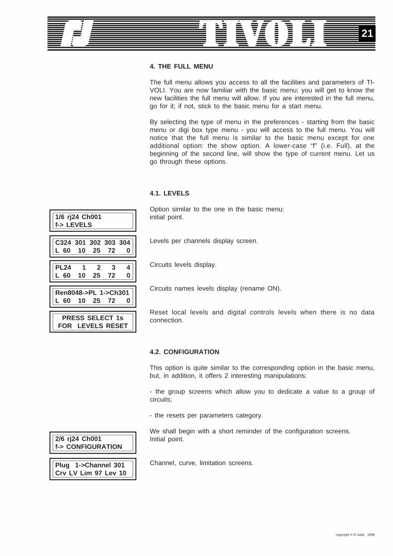
4. THE FULL MENU
The full menu allows you access to all the facilities and parameters of TI-VOLI. You are now familiar with the basic menu; you will get to know thenew facilities the full menu will allow. If you are interested in the full menu,go for it; if not, stick to the basic menu for a start menu.
By selecting the type of menu in the preferences - starting from the basicmenu or digi box type menu - you will access to the full menu. You willnotice that the full menu is similar to the basic menu except for oneadditional option: the show option. A lower-case “f” (i.e. Full), at thebeginning of the second line, will show the type of current menu. Let usgo through these options.
4.1. LEVELS
Option similar to the one in the basic menu:initial point.
Levels per channels display screen.
Circuits levels display.
Circuits names levels display (rename ON).
Reset local levels and digital controls levels when there is no dataconnection.
4.2. CONFIGURATION
This option is quite similar to the corresponding option in the basic menu,but, in addition, it offers 2 interesting manipulations:
- the group screens which allow you to dedicate a value to a group ofcircuits;
- the resets per parameters category.
We shall begin with a short reminder of the configuration screens.Initial point.
Channel, curve, limitation screens.
1/6 rj24 Ch001f-> LEVELS
C324 301 302 303 304L 60 10 25 72 0
PL24 1 2 3 4L 60 10 25 72 0
Ren8048->PL 1->Ch301L 60 10 25 72 0
PRESS SELECT 1s FOR LEVELS RESET
2/6 rj24 Ch001f-> CONFIGURATION
Plug 1->Channel 301Crv LV Lim 97 Lev 10

copyright © R Juliat 1998
22
External controls and local level screen.
Configuration reset .
Starting from a field of parameters, the group screens can be reached bypressing simultaneously the SELECT and “+” keys. Go to the channel 3curve and press SELECT++. Now you are able to set the limits of thegroup: circuits 3 to 4, circuits 3 to 24 or circuits 1 to 5. Then you willselect which curve will be dedicated to the group. Warning: the currentcircuit will be modified even though it is not part of the group.
You reach a group screen from the limitation field.
You reach a group screen from the local value field.
When the patch is ON, you can reach a group screen via the channelfield. You will notice one extra parameter in this screen:CLEAR shows that the first circuit will receive the selected channel (403,in this example), while the others will receive channels in ascending order(404, 405 and 406);
ALL shows that all the circuits of the group (3, 4, 5 et 6, in this example)will receive the same channel (403).
Resetting one parameters category is another possibility. While the confi-guration reset clears out all the parameters, resetting one category affectsonly this one: curve, limitation, local value and channel (when the patchis ON).
For a curves reset: go to the curve field and press simultaneously the EXITand “-” keys.
For a limitation reset: go to the limitation field and press simultaneouslythe EXIT and “-” keys.
For a local values reset: go to the local values field and presssimultaneously the EXIT and “-” keys.
If the patch is ON, you will be able to reset the channels: go to thechannel field and press simultaneously the EXIT and “-” keys.
PL 1->Ren8048->Ch301Crv LT Lim 97 Lev 10
Plug 1-> Channel 301Num 3 Ana 5 Loc 10
PRESS SELECT 1sFOR CONFIG. RESET
PLUG 3 THRU 4 CURVE LV
PLUG 3 THRU 4 LIMITATION FF
PLUG 3 THRU 4 LOCAL
PLUG 3 THRU 6 CHANNEL 403 CLEAR
PLUG 3 THRU 6 CHANNEL 403 ALL
PRESS SELECT 1sFOR CURVES RESET
PRESS SELECT 1sFOR LOCAL RESET
PRESS SELECT 1sFOR CHANNELS RESET
PRESS SELECT 1sFOR LIMITATION RESET
copyright © R Juliat 1998
23
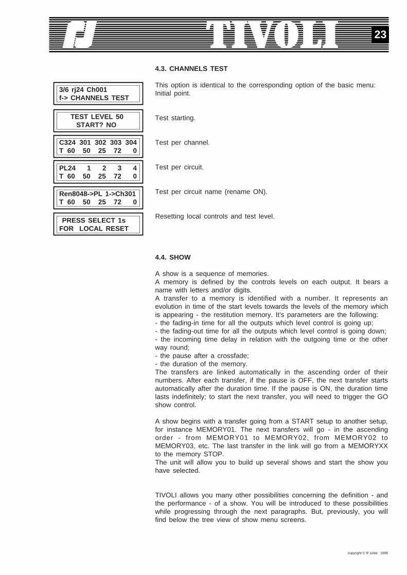
4.3. CHANNELS TEST
This option is identical to the corresponding option of the basic menu:Initial point.
Test starting.
Test per channel.
Test per circuit.
Test per circuit name (rename ON).
Resetting local controls and test level.
4.4. SHOW
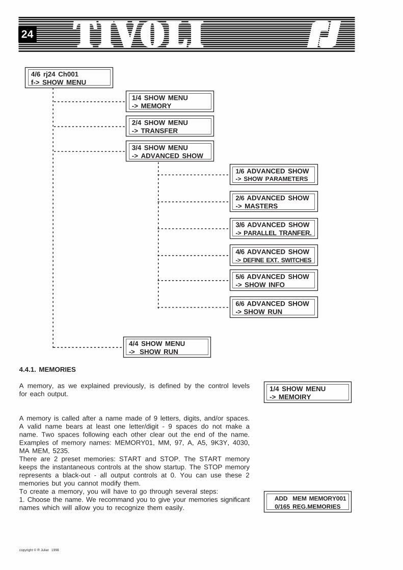
A show is a sequence of memories.A memory is defined by the controls levels on each output. It bears aname with letters and/or digits.A transfer to a memory is identified with a number. It represents anevolution in time of the start levels towards the levels of the memory whichis appearing - the restitution memory. It's parameters are the following:- the fading-in time for all the outputs which level control is going up;- the fading-out time for all the outputs which level control is going down;- the incoming time delay in relation with the outgoing time or the otherway round;- the pause after a crossfade;- the duration of the memory.The transfers are linked automatically in the ascending order of theirnumbers. After each transfer, if the pause is OFF, the next transfer startsautomatically after the duration time. If the pause is ON, the duration timelasts indefinitely; to start the next transfer, you will need to trigger the GOshow control.
A show begins with a transfer going from a START setup to another setup,for instance MEMORY01. The next transfers will go - in the ascendingorder - from MEMORY01 to MEMORY02, from MEMORY02 toMEMORY03, etc. The last transfer in the link will go from a MEMORYXXto the memory STOP.The unit will allow you to build up several shows and start the show youhave selected.
TIVOLI allows you many other possibilities concerning the definition - andthe performance - of a show. You will be introduced to these possibilitieswhile progressing through the next paragraphs. But, previously, you willfind below the tree view of show menu screens.
3/6 rj24 Ch001f-> CHANNELS TEST
TEST LEVEL 50 START? NO
C324 301 302 303 304T 60 50 25 72 0
PL24 1 2 3 4T 60 50 25 72 0
Ren8048->PL 1->Ch301T 60 50 25 72 0
PRESS SELECT 1sFOR LOCAL RESET
copyright © R Juliat 1998
24
4.4.1. MEMORIES
A memory, as we explained previously, is defined by the control levelsfor each output.
A memory is called after a name made of 9 letters, digits, and/or spaces.A valid name bears at least one letter/digit - 9 spaces do not make aname. Two spaces following each other clear out the end of the name.Examples of memory names: MEMORY01, MM, 97, A, A5, 9K3Y, 4030,MA MEM, 5235.There are 2 preset memories: START and STOP. The START memorykeeps the instantaneous controls at the show startup. The STOP memoryrepresents a black-out - all output controls at 0. You can use these 2memories but you cannot modify them.To create a memory, you will have to go through several steps:1. Choose the name. We recommand you to give your memories significantnames which will allow you to recognize them easily.
1/4 SHOW MENU-> MEMOIRY
ADD MEM MEMORY001 0/165 REG.MEMORIES
4/6 rj24 Ch001f-> SHOW MENU
- - - - - - - - - - - - - - - - - - - -
--
--
--
--
--
--
--
--
--
--
--
--
--
--
--
--
--
--
--
--
--
--
--
--
--
--
--
--
--
--
--
--
1/4 SHOW MENU-> MEMORY
- - - - - - - - - - - - - - - - - - - - 2/4 SHOW MENU-> TRANSFER
- - - - - - - - - - - - - - - - - - - - 3/4 SHOW MENU-> ADVANCED SHOW
- - - - - - - - - - - - - - - - - - - -
----
----
----
----
----
----
----
----
----
-
1/6 ADVANCED SHOW-> SHOW PARAMETERS
- - - - - - - - - - - - - - - - - - - - 2/6 ADVANCED SHOW-> MASTERS
- - - - - - - - - - - - - - - - - - - - 5/6 ADVANCED SHOW-> SHOW INFO
- - - - - - - - - - - - - - - - - - - - 6/6 ADVANCED SHOW-> SHOW RUN
- - - - - - - - - - - - - - - - - - - 4/4 SHOW MENU-> SHOW RUN
- - - - - - - - - - - - - - - - - - - - 3/6 ADVANCED SHOW-> PARALLEL TRANFER.
- - - - - - - - - - - - - - - - - - - - 4/6 ADVANCED SHOW-> DEFINE EXT. SWITCHES
copyright © R Juliat 1998
25
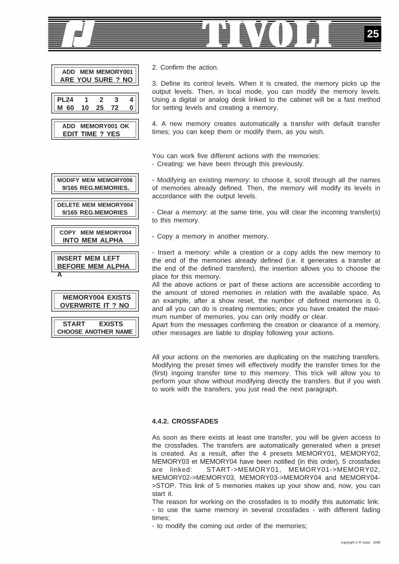
2. Confirm the action.
3. Define its control levels. When it is created, the memory picks up theoutput levels. Then, in local mode, you can modify the memory levels.Using a digital or analog desk linked to the cabinet will be a fast methodfor setting levels and creating a memory.
4. A new memory creates automatically a transfer with default transfertimes; you can keep them or modify them, as you wish.
You can work five different actions with the memories:- Creating: we have been through this previously.
- Modifying an existing memory: to choose it, scroll through all the namesof memories already defined. Then, the memory will modify its levels inaccordance with the output levels.
- Clear a memory: at the same time, you will clear the incoming transfer(s)to this memory.
- Copy a memory in another memory.
- Insert a memory: while a creation or a copy adds the new memory tothe end of the memories already defined (i.e. it generates a transfer atthe end of the defined transfers), the insertion allows you to choose theplace for this memory.All the above actions or part of these actions are accessible according tothe amount of stored memories in relation with the available space. Asan example, after a show reset, the number of defined memories is 0,and all you can do is creating memories; once you have created the maxi-mum number of memories, you can only modify or clear.Apart from the messages confirming the creation or clearance of a memory,other messages are liable to display following your actions.
All your actions on the memories are duplicating on the matching transfers.Modifying the preset times will effectively modify the transfer times for the(first) ingoing transfer time to this memory. This trick will allow you toperform your show without modifying directly the transfers. But if you wishto work with the transfers, you just read the next paragraph.
4.4.2. CROSSFADES
As soon as there exists at least one transfer, you will be given access tothe crossfades. The transfers are automatically generated when a presetis created. As a result, after the 4 presets MEMORY01, MEMORY02,MEMORY03 et MEMORY04 have been notified (in this order), 5 crossfadesare linked: START->MEMORY01, MEMORY01->MEMORY02,MEMORY02->MEMORY03, MEMORY03->MEMORY04 and MEMORY04->STOP. This link of 5 memories makes up your show and, now, you canstart it.The reason for working on the crossfades is to modify this automatic link:- to use the same memory in several crossfades - with different fadingtimes;- to modify the coming out order of the memories;
ADD MEM MEMORY001 ARE YOU SURE ? NO
PL24 1 2 3 4M 60 10 25 72 0
ADD MEMORY001 OK EDIT TIME ? YES
MODIFY MEM MEMORY006 9/165 REG.MEMORIES.
DELETE MEM MEMORY004 9/165 REG.MEMORIES
COPY MEM MEMORY004 INTO MEM ALPHA
INSERT MEM LEFTBEFORE MEM ALPHAA
MEMORY004 EXISTS OVERWRITE IT ? NO
START EXISTSCHOOSE ANOTHER NAME

copyright © R Juliat 1998
26
- to create several sequences (crossfades 1-5; crossfades 6-29; crossfades40-50) to be started by selection (please refer to «start the show» and«show parameters»).
Before declaring new transfers or a new sequence, let us examine closelythe sequence which has been automatically built up after setting up 4presets. The ‘modify crossfade’ option will help us and we can run throughthe 5 fades which bear the numbers 1 to 5.
Each crossfade starts from the preset retrieved by the previous memory -or it starts from the START memory, if this is the first preset of asequence. The fade is accomplished towards a memory and following timesto which you can refer and/or modify. You will also note the lighting out-put during the modification of the fade.We are dealing with a crossfade between two presets - as the display isshowing - one preset is outgoing, the other one is ingoing. More precisely- like we did at the beginning of sub-chapter 4.4. - the fade starts fromthe immediate output levels. These levels do not necessarily coincide withthe levels of the outgoing preset: other outgoing memories or masters inindependently-timed fades are liable to pile up. Knowing this, we shall keepthe term of «crossfade between two memories».The first crossfade takes place between the START memory and the res-titution memory of the fade. It is the only fade through which the sequencecan be started and, at the same time, it acts as the identification of thesequence (read also «Show parameters, first fade»).The last fade, to the STOP memory, which the program adds automatically,helps punctuating the end of a sequence. As you will see in the case ofa loop execution of the sequence, this last fade is not executed. But itrepresents the very end of the sequence, which is an essential informa-tion when several sequences are declared.Each time you will declare a fade to the STOP memory, this fade will closea sequence. If other crossfades are following, they will build another (anew) sequence. Declaring then, in the middle of a sequence, a fading tothe STOP memory will divide this sequence into 2 independant sequences.One reverse modification can concatenate (link) 2 consecutive sequences.
You can operate the crossfades in five different manners:- Modify a crossfade: see above.- Clear a crossfade: the crossfade memory is retained, it is not cleared;the following crossfades are shifted.
- Create a crossfade: you will declare a fade towards an existing memory,either at the end of the last show, either further on, to start a new show.
- Copy of a group of fades towards a fade number.
- Insert a fade: you declare a fade towards an existing memory; thefollowing crossfades are shifted.
2/4 SHOW MENU-> TRANSFER
MODIFY TRANS 5/ 10MEMORY004->MEMORY005
DELETE TRANS 6/ 10MEMORY005->MEMORY006
ADD TRANS 10/ 10 MEMORY009->STOP
COPY TR. 6TILL 10 TO TRANSFER 100
INSERT TRANS 102/104MEMORY006->ALPHA
TR. 6- 10 ->100-104 DONE
copyright © R Juliat 1998
27
During all these actions, the program will help you. For instance, it willtry to protect the last memory of a sequence against being cleared or itwill try to avoid dangerous copies. But you will be entirely free to - andresponsible for - defining your sequence(s). Also you shall pay attentionto the outgoing time of the first fade which runs the outgoing time of theSTART memory.
4.4.3. SHOW EXECUTION
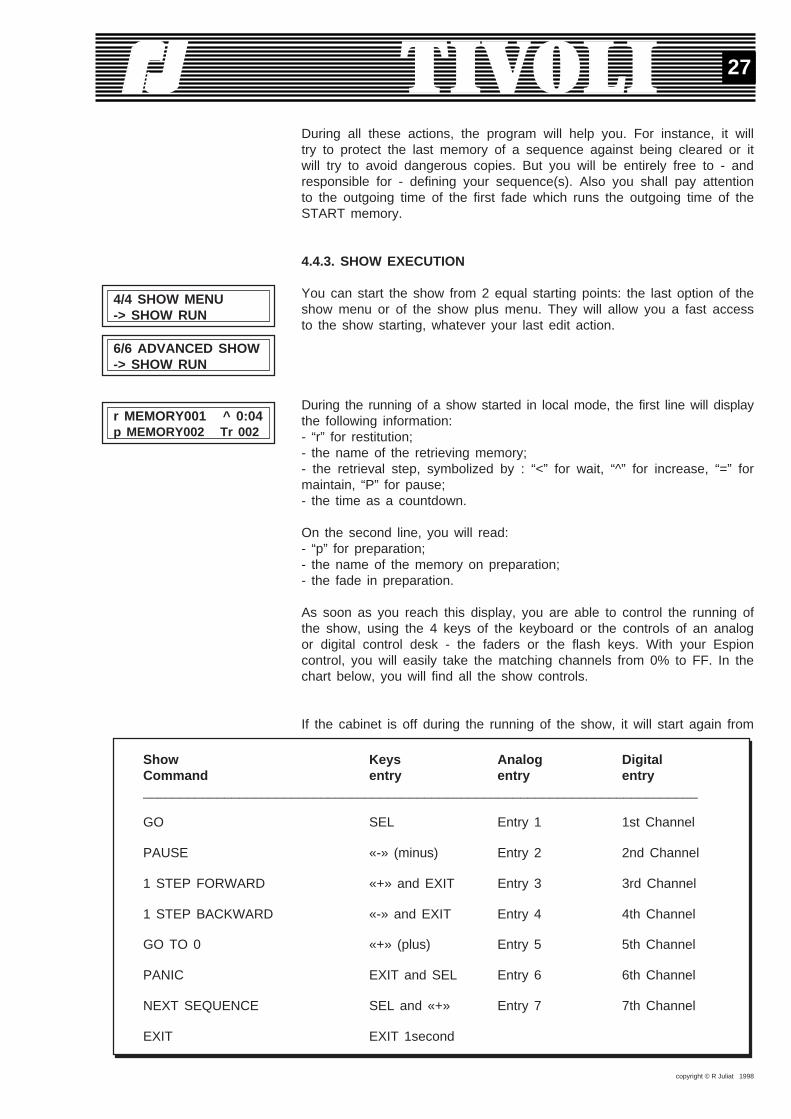
You can start the show from 2 equal starting points: the last option of theshow menu or of the show plus menu. They will allow you a fast accessto the show starting, whatever your last edit action.
During the running of a show started in local mode, the first line will displaythe following information:- “r” for restitution;- the name of the retrieving memory;- the retrieval step, symbolized by : “<” for wait, “^” for increase, “=” formaintain, “P” for pause;- the time as a countdown.
On the second line, you will read:- “p” for preparation;- the name of the memory on preparation;- the fade in preparation.
As soon as you reach this display, you are able to control the running ofthe show, using the 4 keys of the keyboard or the controls of an analogor digital control desk - the faders or the flash keys. With your Espioncontrol, you will easily take the matching channels from 0% to FF. In thechart below, you will find all the show controls.
If the cabinet is off during the running of the show, it will start again from
4/4 SHOW MENU-> SHOW RUN
6/6 ADVANCED SHOW-> SHOW RUN
r MEMORY001 ^ 0:04p MEMORY002 Tr 002
Show Keys Analog DigitalCommand entry entry entry___________________________________________________________________________
GO SEL Entry 1 1st Channel
PAUSE «-» (minus) Entry 2 2nd Channel
1 STEP FORWARD «+» and EXIT Entry 3 3rd Channel
1 STEP BACKWARD «-» and EXIT Entry 4 4th Channel
GO TO 0 «+» (plus) Entry 5 5th Channel
PANIC EXIT and SEL Entry 6 6th Channel
NEXT SEQUENCE SEL and «+» Entry 7 7th Channel
EXIT EXIT 1second

copyright © R Juliat 1998
28
the first fade of the current sequence when the unit is powered up.
Using an external keyboard is another possibility for starting the show. Youwill read more in paragraph 4.4.8.
4.4.4. SHOW PLUS MENUThis menu gathers the most powerful possibilities of the show: you willget to know them in the next paragraphs.
4.4.5. SHOW PARAMETERSFor each of the show parameters we are going to describe its interest anddefault value.
When the unit is switched on, there are 3 possibilities to start the show:- the manual start (MANUAL): to start the show, you will retrace your stepsfrom the start menu to the «start the show» option of the show menu;- the automatic start (AUTO): when the unit is switched on, the executionshow screen is displayed and the show begins;- the panic start (PANIC): the unit always positions itself on the executionshow screen and it retrieves the ‘panic’ output levels while waiting for auser’s control.
If TIVOLI is switched off during the running of a show, the next time it isswitched on the unit will start anew from the beginning.Default value on show start-up: manual.
The ‘first fade’ parameter represents the first fade to be run when a showis starting.
When several sequences are defined in the unit, you can select asequence from its first fade. The “+” key looks up a begin the sequencefade and displays it. The “-” key jumps back to the first fade of the firstsequence.If you clear the first fade from the current sequence or if you displace itin the fades edit screen, the first fade to be set is not automaticallyupdated and you will be surprised when you start the show. But, it willbe updated via the first fade field.The variable will eventually keep the last value, generated from the showcontrol ‘GO TO THE NEXT SEQUENCE’ given in the course of the showexecution.
The Repetition parameter controls the end of the show. When its value isOFF, the show will stop at the end of the last crossfade - usually, a fadeto the STOP memory. When its value is ON - its default value - the firstfade takes for the fade to STOP, so that the show skips the fade to black-out (STOP) and starts again from the beginning.
3/4 SHOW MENU-> ADVANCED
1/6 ADVANCED SHOW-> SHOW PARAMETERS
1/9 SHOW PARAMETERS START MANUAL
2/9 SHOW PARAMETERS FIRST TRANSFER 1
3/9 SHOW PARAMETERS REPETITION ON
copyright © R Juliat 1998
29
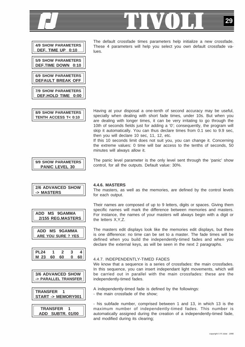
The default crossfade times parameters help initialize a new crossfade.These 4 parameters will help you select you own default crossfade va-lues.
Having at your disposal a one-tenth of second accuracy may be useful,specially when dealing with short fade times, under 10s. But when youare dealing with longer times, it can be very irritating to go through the10th of seconds fields just for adding a ‘0’; consequently, the program willskip it automatically. You can thus declare times from 0.1 sec to 9.9 sec,then you will declare 10 sec, 11, 12, etc.If this 10 seconds limit does not suit you, you can change it. Concerningthe extreme values: 0 time will bar access to the tenths of seconds, 50minutes will always allow it.
The panic level parameter is the only level sent through the ‘panic’ showcontrol, for all the outputs. Default value: 30%.
4.4.6. MASTERSThe masters, as well as the memories, are defined by the control levelsfor each output.
Their names are composed of up to 9 letters, digits or spaces. Giving themspecific names will mark the difference between memories and masters.For instance, the names of your masters will always begin with a digit orthe letters X,Y,Z.
The masters edit displays look like the memories edit displays, but thereis one difference: no time can be set to a master. The fade times will bedefined when you build the independently-timed fades and when youdeclare the external keys, as will be seen in the next 2 paragraphs.
4.4.7. INDEPENDENTLY-TIMED FADESWe know that a sequence is a series of crossfades: the main crossfades.In this sequence, you can insert independant light movements, which willbe carried out in parallel with the main crossfades: these are theindependently-timed fades.
A independently-timed fade is defined by the followings:- the main crossfade of the show;
- his subfade number, comprised between 1 and 13, in which 13 is themaximum number of independently-timed fades. This number isautomatically assigned during the creation of a independently-timed fade,and modified during its clearing;
4/9 SHOW PARAMETERS DEF. TIME UP 0:10
5/9 SHOW PARAMETERSDEF.TIME DOWN 0:10
6/9 SHOW PARAMETERSDEFAULT BREAK OFF
7/9 SHOW PARAMETERS DEF.HOLD TIME 0:00
8/9 SHOW PARAMETERSTENTH ACCESS T< 0:10
2/6 ADVANCED SHOW-> MASTERS
ADD MS 9GAMMA 2/155 REG.MASTERS
ADD MS 9GAMMA ARE YOU SURE ? YES
PL24 1 2 3 4M 23 60 60 0 60
TRANSFER 1START -> MEMORY001
TRANSFER 1 ADD SUBTR. 01/00
3/6 ADVANCED SHOW-> PARALLEL TRANSFER
9/9 SHOW PARAMETERS PANIC LEVEL 30

copyright © R Juliat 1998
30
- the related master;
- the delay time between its beginning and the beginning of the maincrossfade;
- the ingoing time of the master, i.e. the required time for the significantlevels (above zero) of the master to be reached up or down;
- the duration of the significant levels of the master;
- the fading out time, during which the significant levels of the master fadedown to 0;
You can create, modify and delete a independently-timed fade. A confir-mation signal will show before the edit of a independently-timed fade whichwill be followed by an accomplishment message.
The default values for the ingoing, duration and outgoing times, arerespectively the ingoing, duration and outgoing times for the show.To know the number of independently-timed fades for each crossfade, goto the number of the main crossfade in the subtransfers edit mask andscan it.
The maximal number of parallel effects (main crossfades included) is 15.Some precisions concerning a main crossfade edit:1. Deleting a main crossfade will clear out all the related independently-timed fades.2. Shifting main crossfades - by deleting or inserting a crossfade - willobviously maintain the existing links between the main crossfades and therelated independently-timed fades.3. Copying a group of crossfades will only copy the main crossfades: youwill have to create new independently-timed fades for the new group.
4.4.8. EXTERNAL SWITCHESConcerning the hardware, the external switches are 15 flash contacts onthe wires 1-15 of the female SUB D25 socket; the 16th button, locatedon wire 16, is an ON/OFF button.When button 16 switches ON, the external switches are controlling the ca-binet and the corresponding screen is displaying.
But before, activate the buttons, we ought to define them. Setting backbutton 16 to OFF will give you back the control of the unit.
Defining an external switch means assigning it a master, an ingoing timeand an outgoing time for the levels which are controlled by the master.The times are defined with an one second accuracy.
SUBTRANSFER 1-01 MASTER 9GAMMA
SUBTRANSFER 1-01 DELAY 0:00.0
SUBTRANSFER 1-01 APP. TIME 0:10.0
SUBTRANSFER 1-01 HOLD TIME 0:00.0
SUBTRANSFER 1-01 DISAPP.TIME 0:10.0
TRANSFER 1 ARE YOU SURE ? YES
ADD SUBTRANSFER 1-01 DONE
TRANSFER 1 ADD SUBTR. 01/00
0 ACTIVE SHITCHES MASTER
4/6 ADVANCED SHOW->DEFINE EXT.SWITCHS
EXTERNAL SWITCH 1 MASTER 9GAMMA
EXTERNAL SWITCH 1 APP. TIME 0:12
EXTERNAL SWITCH 1 DISAPP.TIME 0:03

copyright © R Juliat 1998
31
You defined 5 buttons. Bring button 16 back to ON and press 3 of the 5defined switches. The display on the external switches screen will showdifferently.
This control screen will allow you to run through all the active masters;the signs showing on the second line are: “^” meaning going up, “=”meaning unchanged, and “v” meaning going down.The external switches will also allow you to start a show and control it.You only have to link the buttons to the show controls. These controlsare still called “masters” but you will note 2 differences with the propermasters:
- the show control masters have no ingoing or outgoing time - if you pushthe switch, the command starts at once;- these are submaster controls, thus they do not show on the externalkeys screen.The next external keys will be linked to the show controls (see also the4.4.3 paragraph):
Switch # Show control 9 GO 10 PAUSE 11 STEP FORW 12 STEP BACK 13 GO TO 0 14 PANIC 15 NEXT SEQ 16 OFF EXIT
There are 3 possibilities for using the external keys:1. Controlling masters: we advise you to delete the 9-15 controls or put“real” masters in their place.2. Controllin a show: you can keep the default controls, double them, getrid of some of them (PANIC or NEXT SEQ, for example).3. Controlling both masters and show; by mixing up, in real-time, therunning of the show and masters outputs, you will be free to use the fullpower and richness of the lighting outputs allowed by TIVOLI.
4.4.9. INFO SHOWThe info show will give you a summary with the number of show elements(memories, masters and crossfades) that you have defined, as well as theavailable space for each element.
Memories and masters share a common space of 165 steps. Recordinga memory reduces the available memory space as well as the mastersspace; and conversely. Likewise, the (main) crossfades and theindependently-timed fades share a common space of 256 steps.
3 ACTIVE SWITCHES MASTER ^ 9GAMMA
5/6 ADVANCED SHOW-> SHOW INFORMATION
1/4 SHOW INFO MEMORIES 10/160
2/4 SHOW INFO MASTERS 5/155
3/4 SHOW INFO TRANSFERS 11/250
4/4 SHOW INFOPARALLEL TR. 6/245
EXTERNAL SWITCH 15 MASTER NEXT SEQ
copyright © R Juliat 1998
32
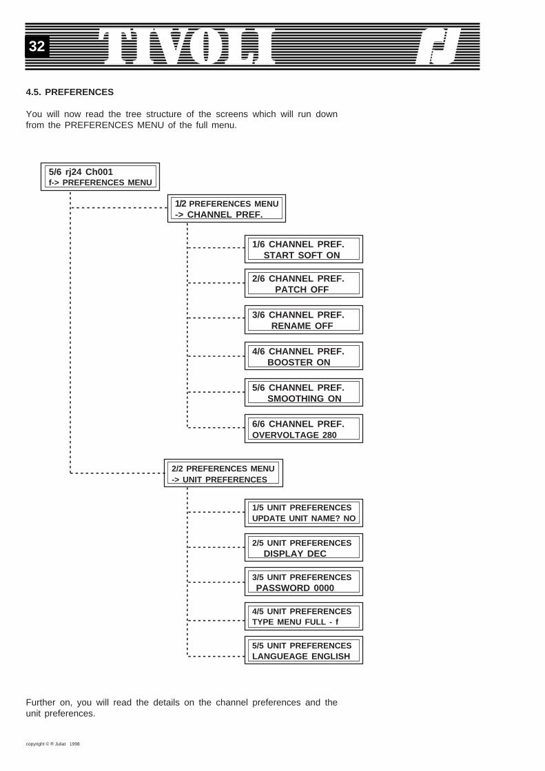
4.5. PREFERENCES
You will now read the tree structure of the screens which will run downfrom the PREFERENCES MENU of the full menu.
5/6 rj24 Ch001f-> PREFERENCES MENU
1/6 CHANNEL PREF. START SOFT ON
2/2 PREFERENCES MENU-> UNIT PREFERENCES
1/5 UNIT PREFERENCESUPDATE UNIT NAME? NO
2/5 UNIT PREFERENCES DISPLAY DEC
3/5 UNIT PREFERENCES PASSWORD 0000
2/6 CHANNEL PREF. PATCH OFF
3/6 CHANNEL PREF. RENAME OFF
4/6 CHANNEL PREF. BOOSTER ON
5/6 CHANNEL PREF. SMOOTHING ON
6/6 CHANNEL PREF.OVERVOLTAGE 280
4/5 UNIT PREFERENCESTYPE MENU FULL - f
5/5 UNIT PREFERENCESLANGUEAGE ENGLISH
1/2 PREFERENCES MENU-> CHANNEL PREF.
- - - - - - - - - - - - - - - - - - -
----
----
----
----
----
----
----
----
----
----
----
----
----
----
-
- - - - - - - - - - - - - - - - - - -
----
----
----
----
----
----
----
----
----
----
----
- - - - - - - - - - - -
- - - - - - - - - - - -
- - - - - - - - - - - -
- - - - - - - - - - - -
- - - - - - - - - - - -
- - - - - - - - - - - -
----
----
----
----
----
----
----
----
---
- - - - - - - - - - - -
- - - - - - - - - - - -
- - - - - - - - - - - -
- - - - - - - - - - - -
- - - - - - - - - - - -
Further on, you will read the details on the channel preferences and theunit preferences.
copyright © R Juliat 1998
33
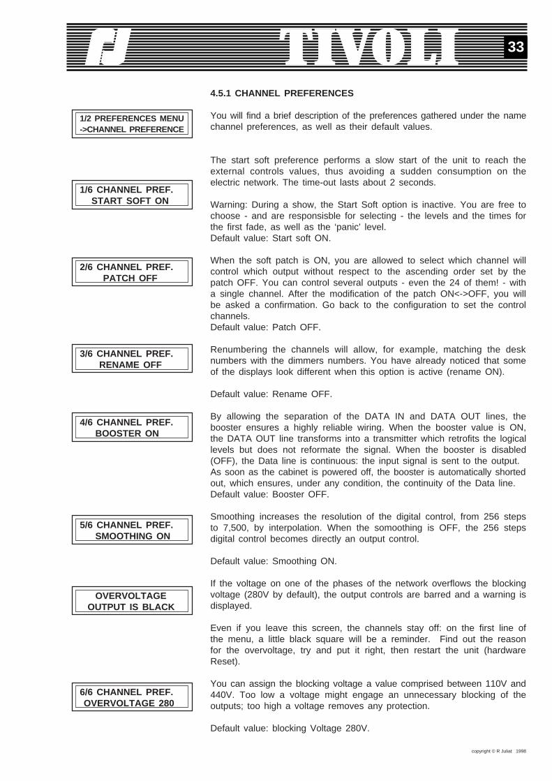
4.5.1 CHANNEL PREFERENCES
You will find a brief description of the preferences gathered under the namechannel preferences, as well as their default values.
The start soft preference performs a slow start of the unit to reach theexternal controls values, thus avoiding a sudden consumption on theelectric network. The time-out lasts about 2 seconds.
Warning: During a show, the Start Soft option is inactive. You are free tochoose - and are responsisble for selecting - the levels and the times forthe first fade, as well as the ‘panic’ level.Default value: Start soft ON.
When the soft patch is ON, you are allowed to select which channel willcontrol which output without respect to the ascending order set by thepatch OFF. You can control several outputs - even the 24 of them! - witha single channel. After the modification of the patch ON<->OFF, you willbe asked a confirmation. Go back to the configuration to set the controlchannels.Default value: Patch OFF.
Renumbering the channels will allow, for example, matching the desknumbers with the dimmers numbers. You have already noticed that someof the displays look different when this option is active (rename ON).
Default value: Rename OFF.
By allowing the separation of the DATA IN and DATA OUT lines, thebooster ensures a highly reliable wiring. When the booster value is ON,the DATA OUT line transforms into a transmitter which retrofits the logicallevels but does not reformate the signal. When the booster is disabled(OFF), the Data line is continuous: the input signal is sent to the output.As soon as the cabinet is powered off, the booster is automatically shortedout, which ensures, under any condition, the continuity of the Data line.Default value: Booster OFF.
Smoothing increases the resolution of the digital control, from 256 stepsto 7,500, by interpolation. When the somoothing is OFF, the 256 stepsdigital control becomes directly an output control.
Default value: Smoothing ON.
If the voltage on one of the phases of the network overflows the blockingvoltage (280V by default), the output controls are barred and a warning isdisplayed.
Even if you leave this screen, the channels stay off: on the first line ofthe menu, a little black square will be a reminder. Find out the reasonfor the overvoltage, try and put it right, then restart the unit (hardwareReset).
You can assign the blocking voltage a value comprised between 110V and440V. Too low a voltage might engage an unnecessary blocking of theoutputs; too high a voltage removes any protection.
Default value: blocking Voltage 280V.
1/2 PREFERENCES MENU->CHANNEL PREFERENCE
1/6 CHANNEL PREF. START SOFT ON
2/6 CHANNEL PREF. PATCH OFF
3/6 CHANNEL PREF. RENAME OFF
4/6 CHANNEL PREF. BOOSTER ON
5/6 CHANNEL PREF. SMOOTHING ON
OVERVOLTAGE OUTPUT IS BLACK
6/6 CHANNEL PREF. OVERVOLTAGE 280
copyright © R Juliat 1998
34
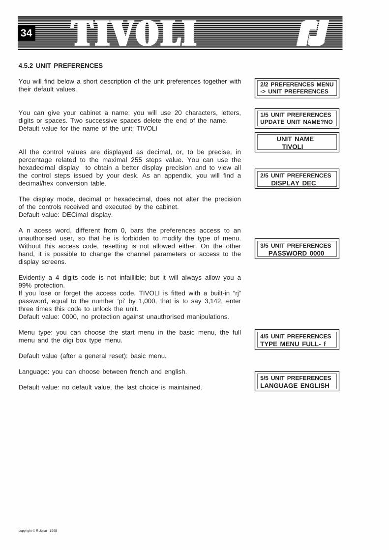
4.5.2 UNIT PREFERENCES
You will find below a short description of the unit preferences together withtheir default values.
You can give your cabinet a name; you will use 20 characters, letters,digits or spaces. Two successive spaces delete the end of the name.Default value for the name of the unit: TIVOLI
All the control values are displayed as decimal, or, to be precise, inpercentage related to the maximal 255 steps value. You can use thehexadecimal display to obtain a better display precision and to view allthe control steps issued by your desk. As an appendix, you will find adecimal/hex conversion table.
The display mode, decimal or hexadecimal, does not alter the precisionof the controls received and executed by the cabinet.Default value: DECimal display.
A n acess word, different from 0, bars the preferences access to anunauthorised user, so that he is forbidden to modify the type of menu.Without this access code, resetting is not allowed either. On the otherhand, it is possible to change the channel parameters or access to thedisplay screens.
Evidently a 4 digits code is not infaillible; but it will always allow you a99% protection.If you lose or forget the access code, TIVOLI is fitted with a built-in “rj”password, equal to the number ‘pi’ by 1,000, that is to say 3,142; enterthree times this code to unlock the unit.Default value: 0000, no protection against unauthorised manipulations.
Menu type: you can choose the start menu in the basic menu, the fullmenu and the digi box type menu.
Default value (after a general reset): basic menu.
Language: you can choose between french and english.
Default value: no default value, the last choice is maintained.
2/2 PREFERENCES MENU-> UNIT PREFERENCES
1/5 UNIT PREFERENCESUPDATE UNIT NAME?NO
4/5 UNIT PREFERENCESTYPE MENU FULL- f
5/5 UNIT PREFERENCESLANGUAGE ENGLISH
UNIT NAME TIVOLI
2/5 UNIT PREFERENCES DISPLAY DEC
3/5 UNIT PREFERENCES PASSWORD 0000

copyright © R Juliat 1998
35
4.6. UNIT TEST & INFO
You will now read the tree structure of the screens which will run downfrom the UNIT TEST & INFO MENU of the full menu.
6/6 rj24 Ch001f-> UNIT TEST&INFO
1/7 MAINS INFOU1 min220 226 Max228
4/7 MAINS INFOPHASE 1 -> PRESENT
7/7 MAINS INFO FREQUENCY 50.0Hz
1/6 UNIT TEST&INFO-> MAINS INFO
1/2 PROTOCOL DMX PACKET LENGTH 128
2/2 PROTOCOL DMXERRORS/1000PCK 0
2/6 UNIT TEST&INFO->INFO DMX
T1= 30°F FAN 1 ONT2= 32°F FAN 2 OFF
3/6 UNIT TEST&INFO-> FANS INFO/TEST
1 = = = > = = = = 89 = = = = = > = =16
5/6 UNIT TEST&INFO->RAM TEST
RAM TEST 0200-1FFF O.K.
4/6 UNIT TEST&INFO-> EXT. SWITCHES TEST
RAM TEST 8000-9FFF TESTING
1/3 PRODUCT INFO Robert Juliat
3/3 PRODUCT INFOPh(33)3.44.26.51.89
3/3 PRODUCT INFO VERSION V1-01
6/6 UNIT TEST&INFO->PRODUCT INFO
----
----
----
----
----
----
----
----
----
----
----
----
----
----
----
----
----
----
----
----
----
----
----
- - - - - - - -
- - - - - - - - - - - - - - - - - - - - -
- - - - - - - - -
- - - - - - - - -
- - - - - - - - -
- - - - - - - - -
--
--
--
--
--
--
--
--
- - - - - - - - - - - - - - - - - - - - -
- - - - - - - - - - - - - - - - - - - - -
- - - - - - - - - - - - - - - - - - - - -
- - - - - - - - - - - - - - - - - - - - -----
----
- - - - - - - - - - - - - - - - - - - - ----
- - - - - - - - - - - - - - - - - - - - -
----
----
---
- - - - - - - - - - - - - - - - - - - - -
- - - - - - - - - - - - - - - - - - - - -
- - - - - - - - - - - - - - - - - - - - -
----
----
----
----
- - - - - - - - - - - - - - - - - - - - -
- - - - - - - - - - - - - - - - - - - - -
--
-
- - - - - - - - -
---
--
-
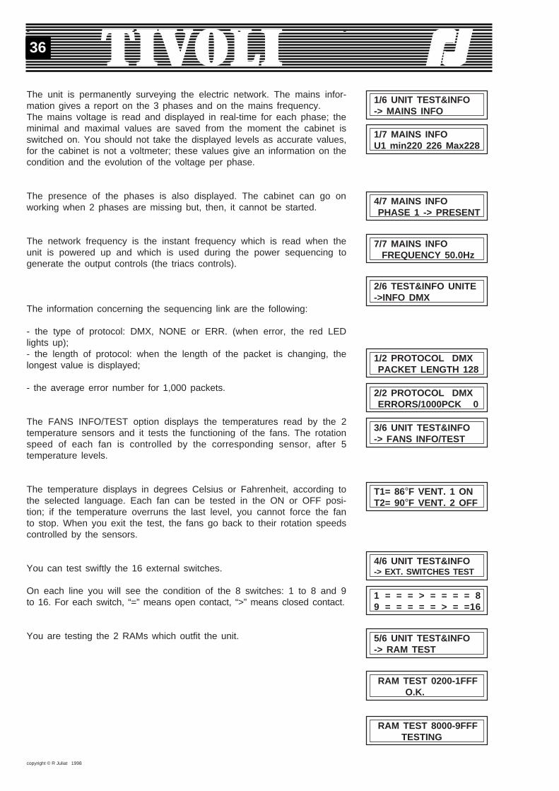
copyright © R Juliat 1998
36
The unit is permanently surveying the electric network. The mains infor-mation gives a report on the 3 phases and on the mains frequency.The mains voltage is read and displayed in real-time for each phase; theminimal and maximal values are saved from the moment the cabinet isswitched on. You should not take the displayed levels as accurate values,for the cabinet is not a voltmeter; these values give an information on thecondition and the evolution of the voltage per phase.
The presence of the phases is also displayed. The cabinet can go onworking when 2 phases are missing but, then, it cannot be started.
The network frequency is the instant frequency which is read when theunit is powered up and which is used during the power sequencing togenerate the output controls (the triacs controls).
The information concerning the sequencing link are the following:
- the type of protocol: DMX, NONE or ERR. (when error, the red LEDlights up);- the length of protocol: when the length of the packet is changing, thelongest value is displayed;
- the average error number for 1,000 packets.
The FANS INFO/TEST option displays the temperatures read by the 2temperature sensors and it tests the functioning of the fans. The rotationspeed of each fan is controlled by the corresponding sensor, after 5temperature levels.
The temperature displays in degrees Celsius or Fahrenheit, according tothe selected language. Each fan can be tested in the ON or OFF posi-tion; if the temperature overruns the last level, you cannot force the fanto stop. When you exit the test, the fans go back to their rotation speedscontrolled by the sensors.
You can test swiftly the 16 external switches.
On each line you will see the condition of the 8 switches: 1 to 8 and 9to 16. For each switch, “=” means open contact, “>” means closed contact.
You are testing the 2 RAMs which outfit the unit.
1/6 UNIT TEST&INFO-> MAINS INFO
1/7 MAINS INFOU1 min220 226 Max228
4/7 MAINS INFO PHASE 1 -> PRESENT
7/7 MAINS INFO FREQUENCY 50.0Hz
2/6 TEST&INFO UNITE->INFO DMX
1/2 PROTOCOL DMX PACKET LENGTH 128
2/2 PROTOCOL DMX ERRORS/1000PCK 0
RAM TEST 8000-9FFF TESTING
- - - -
T1= 86°F VENT. 1 ONT2= 90°F VENT. 2 OFF
4/6 UNIT TEST&INFO-> EXT. SWITCHES TEST
1 = = = > = = = = 89 = = = = = > = =16
3/6 UNIT TEST&INFO-> FANS INFO/TEST
5/6 UNIT TEST&INFO-> RAM TEST
RAM TEST 0200-1FFF O.K.

copyright © R Juliat 1998
37
3/3 PRODUCT INFO VERSION V1-01
6/6 UNIT TEST&INFO->PRODUCT INFO
1/3 PRODUCT INFO Robert Juliat
3/3 PRODUCT INFOPh.(33)3.44.26.51.89
Reset Concerned parameters Menu Option
Memories Mémories & transfers Show MEMORY
Transfer Transfers Show TRANSFER
Show Mémoires, masters, Show SHOW MENUtransferts, paramètres
Show RUN SHOW
Advanced show SHOW INFO
Advanced show RUN SHOW
Show parameters Show parameters Advanced show SHOW PARAMETERS
Masters Masters, ext. switches, Advanced show MEMORYparallel transfers
Parallel Tr. Parallel transfers Advanced show TRANSFER
Ext. switches External switches Advanced show MEMORY
Among the information concerning the product, you will find the name ofthe manufacturer, his phone number and the version number of the TI-VOLI program.
4.7. SOFTWARE RESET
A software reset forces the affected parameters to their default values. Bypressing together the EXIT and “-” keys you can start a software resetfrom several places.In the full menu, the options which are similar to the basic menu optionsgenerate the same resets than those which are described in the subchapter2.7.In the configuration screen, the resets per parameter class are describedin sub-chapter 4.2.

copyright © R Juliat 1998
38
5. APPENDIX
Décimal (%). Hexadécimal.Les pas DMX/DMX steps.
Les pas DMX/DMX steps. Décimal (%). Hexadécimal.
0
1
2
3
4
5
6
7
8
9
10
11
12
13
14
15
16
17
18
19
20
21
22
23
24
25
26
27
28
29
30
31
0
0
1
1
2
2
2
3
3
4
4
4
5
5
5
6
6
7
7
7
8
8
9
9
9
10
10
11
11
11
12
12
00
01
02
03
04
05
06
07
08
09
0A
0b
0C
0d
0E
0F
10
11
12
13
14
15
16
17
18
19
1A
1b
1C
1d
1E
1F
32
33
34
35
36
37
38
39
40
41
42
43
44
45
46
47
48
49
50
51
52
53
54
55
56
57
58
59
60
61
62
63
13
13
13
14
14
15
15
15
16
16
16
17
17
18
18
18
19
19
20
20
20
21
21
22
22
22
23
23
24
24
24
25
20
21
22
23
24
25
26
27
28
29
2A
2b
2C
2d
2E
2F
30
31
32
33
34
35
36
37
38
39
3A
3b
3C
3d
3E
3F
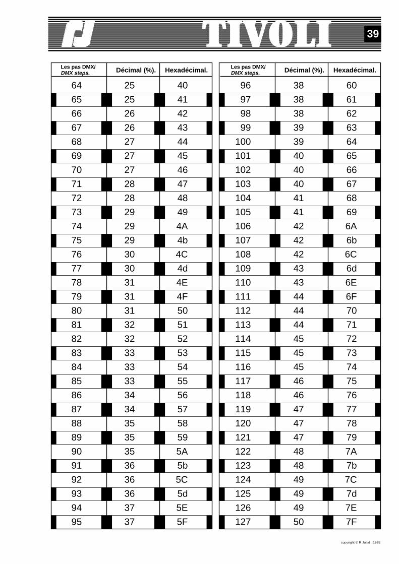
copyright © R Juliat 1998
39
Décimal (%). Hexadécimal.Les pas DMX/DMX steps.
Les pas DMX/DMX steps. Décimal (%). Hexadécimal.
64
65
66
67
68
69
70
71
72
73
74
75
76
77
78
79
80
81
82
83
84
85
86
87
88
89
90
91
92
93
94
95
25
25
26
26
27
27
27
28
28
29
29
29
30
30
31
31
31
32
32
33
33
33
34
34
35
35
35
36
36
36
37
37
40
41
42
43
44
45
46
47
48
49
4A
4b
4C
4d
4E
4F
50
51
52
53
54
55
56
57
58
59
5A
5b
5C
5d
5E
5F
96
97
98
99
100
101
102
103
104
105
106
107
108
109
110
111
112
113
114
115
116
117
118
119
120
121
122
123
124
125
126
127
38
38
38
39
39
40
40
40
41
41
42
42
42
43
43
44
44
44
45
45
45
46
46
47
47
47
48
48
49
49
49
50
60
61
62
63
64
65
66
67
68
69
6A
6b
6C
6d
6E
6F
70
71
72
73
74
75
76
77
78
79
7A
7b
7C
7d
7E
7F
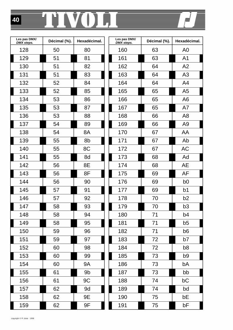
copyright © R Juliat 1998
40
Décimal (%). Hexadécimal.Les pas DMX/DMX steps.
Les pas DMX/DMX steps. Décimal (%). Hexadécimal.
128
129
130
131
132
133
134
135
136
137
138
139
140
141
142
143
144
145
146
147
148
149
150
151
152
153
154
155
156
157
158
159
50
51
51
51
52
52
53
53
53
54
54
55
55
55
56
56
56
57
57
58
58
58
59
59
60
60
60
61
61
62
62
62
80
81
82
83
84
85
86
87
88
89
8A
8b
8C
8d
8E
8F
90
91
92
93
94
95
96
97
98
99
9A
9b
9C
9d
9E
9F
160
161
162
163
164
165
166
167
168
169
170
171
172
173
174
175
176
177
178
179
180
181
182
183
184
185
186
187
188
189
190
191
63
63
64
64
64
65
65
65
66
66
67
67
67
68
68
69
69
69
70
70
71
71
71
72
72
73
73
73
74
74
75
75
A0
A1
A2
A3
A4
A5
A6
A7
A8
A9
AA
Ab
AC
Ad
AE
AF
b0
b1
b2
b3
b4
b5
b6
b7
b8
b9
bA
bb
bC
bd
bE
bF
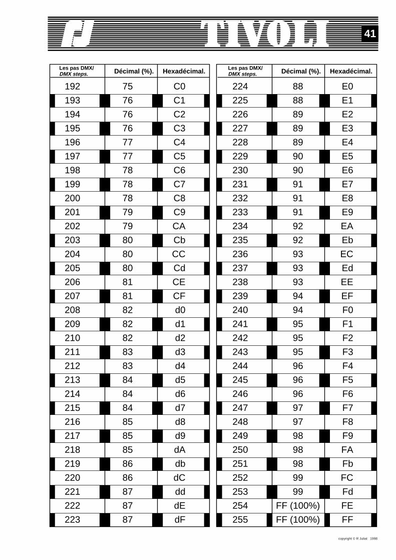
copyright © R Juliat 1998
41
Décimal (%). Hexadécimal.Les pas DMX/DMX steps.
Les pas DMX/DMX steps. Décimal (%). Hexadécimal.
192
193
194
195
196
197
198
199
200
201
202
203
204
205
206
207
208
209
210
211
212
213
214
215
216
217
218
219
220
221
222
223
75
76
76
76
77
77
78
78
78
79
79
80
80
80
81
81
82
82
82
83
83
84
84
84
85
85
85
86
86
87
87
87
C0
C1
C2
C3
C4
C5
C6
C7
C8
C9
CA
Cb
CC
Cd
CE
CF
d0
d1
d2
d3
d4
d5
d6
d7
d8
d9
dA
db
dC
dd
dE
dF
224
225
226
227
228
229
230
231
232
233
234
235
236
237
238
239
240
241
242
243
244
245
246
247
248
249
250
251
252
253
254
255
88
88
89
89
89
90
90
91
91
91
92
92
93
93
93
94
94
95
95
95
96
96
96
97
97
98
98
98
99
99
FF (100%)
FF (100%)
E0
E1
E2
E3
E4
E5
E6
E7
E8
E9
EA
Eb
EC
Ed
EE
EF
F0
F1
F2
F3
F4
F5
F6
F7
F8
F9
FA
Fb
FC
Fd
FE
FF
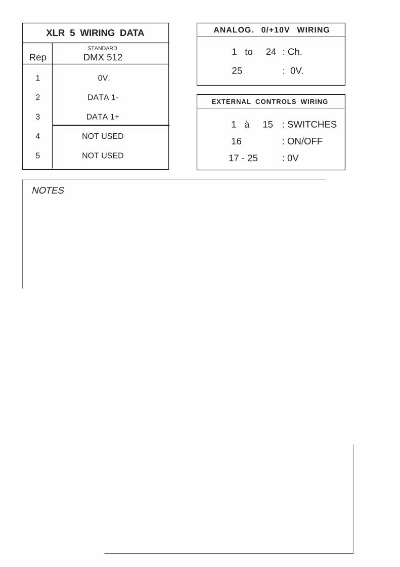
Rep DMX 512
NOTES
1 0V.
2 DATA 1-
3 DATA 1+
4 NOT USED
5 NOT USED
STANDARD 1 to 24 : Ch.
25 : 0V.
XLR 5 WIRING DATA ANALOG. 0/+10V WIRING
1 à 15 : SWITCHES
16 : ON/OFF
17 - 25 : 0V
EXTERNAL CONTROLS WIRING