robo cylinder position controller scon series, 6 … · 2016-09-26 · robo cylinder position...
TRANSCRIPT
ROBO Cylinder Position Controller SCON Series, 6-axis Type
w w w . i n t e l l i g e n t a c t u a t o r. c o m

Combining six RCS2/RCS3 position controllers into one unit
Space-saving, low-cost dedicated network multi-axis controller
ROBO Cylinder <RCS2 series>
ROBO Cylinder <RCS3 series>
Single-axis robot<ISA/ISB series, NS series, RS series, etc.>
12W
20W
30W
60W
100W
150W
200W
Six RCS2/RCS3 (SCON-CA) controllers are combined into one unit to save the installation space and achieve significant reduction in total cost.
In implementations where many SCON controllers are used, switching to MSCON controllers will save the controller installation space to a half or even less. As the controller panel size becomes smaller, cost drops significantly.
When teaching the moving position of each axis, the SCON controller requires that the teaching tool (cable) be disconnected from/connected to each controller one by one. With the MSCON controller, all you need is to switch the screen to change the data input axis, which saves the adjustment time.
Space-saving, low-cost, and easy to use1
Control panel Control panel
SCON-CA MSCON
<Actuators Supported by MSCON>
<Easy Teaching> <Before> <MSCON>
The cable must be disconnected from/connected to each
controller one by one.
All you need is to switch the screen.
* Linear servo actuators are not supported.
Approx. 65% smaller
1

The offboard tuning function increases the acceleration/deceleration speed when the load is small, and decreases the acceleration/deceleration when the load is large, to ensure optimal operation settings according to the load.
Offboard tuning function to enhance actuator payload capacity3
The total number of times the actuator has moved, and total distance travelled, are calculated and recorded in the controller, and a signal will be output to an external device once the preset count or distance is exceeded. This function lets you know when to add grease or carry out periodic inspection.
Calculating the total number of moves and total distance travelled to alert when maintenance is due5
The vibration control function has been added to prevent the work from shaking (vibrating) on the actuator slider as the slider moves. The wait time for vibration to stabilize is shorter and the cycle time can also be shortened.
Vibration control function for shorter cycle time4
The additional clock function makes it easy to analyze alarms as the alarm history is based on time of generation. (Time data will be retained for 10 days after the power is turned off.)
Calendar function to save alarm generation times6
MSCON controllers can be connected directly to key field networks such as DeviceNet, CC-Link, PROFIBUS-DP, MECHATROLINK(*), CompoNet, EtherCAT(*) and EtherNet/IP.
Movement by numerical specification via Field network Substantially shorter transmission time2
Features of Network Specification
Specifications supporting the networks indicated by (*) will be available soon.
(Available soon)
(Available soon)
256 positioning points per axis Moving the actuator after numerically specifying the position to move to, and the speedChecking the current position in real time Significantly shorter communication time within the controller (approx. one-sixth compared to conventional controllers)
2

MSCONseries
CType
( )Motor MotorNumber
of axesEncoder
(Specs for 1st axis) (Specs for axis 2 - 6)
EncoderOption Option I/O type Power/voltage
OI/O cable
length
DV DeviceNet connection specification
CC CC-Link connection specification
PR PROFIBUS-DP connection specification
CN CompoNet connection specification
ML MECHATROLINK II connection specification
EC EtherCAT connection specification
EP EtherNet/IP connection specification
0 No cable
* The MSCON is available only in network specifications and does not come with I/O cables.
(Note) ML and EC specifications will be available soon.
I Incremental
A Absolute
12 12W servo motor
20 20W servo motor
30D 30W servo motor
30R 30W servo motor(RS series)
60 60W servo motor
100 100W servo motor
150 150W servo motor
200 200W servo motor
1 Single-axis model
2 2-axis model
3 3-axis model
4 4-axis model
5 5-axis model
6 6-axis model
1 AC100V
2 AC200VHA High acceleration/
deceleration type
Model Description
Model List/Standard Price
Available soon (Note)
3
MSCON Controller
Model MSCON-C
External view
I/O type
DeviceNet connection specification
CC-Link connection specification
PROFIBUS-DP connection specification
CompoNetconnection specification
MECHATROLINK IIconnection specification
(Note)
EtherCATconnection specification
(Note)
EtherNet/IPconnection specification
I/O type model code DV CC PR CN ML EC EPNumber of axes Encoder Standard price
1 axis
Incremental — — — — — — —
Absolute — — — — — — —
2 axis
Incremental — — — — — — —
Absolute — — — — — — —
3 axis
Incremental — — — — — — —
Absolute — — — — — — —
4 axis
Incremental — — — — — — —
Absolute — — — — — — —
5 axis
Incremental — — — — — — —
Absolute — — — — — — —
6 axis
Incremental — — — — — — —
Absolute — — — — — — —
Stan
dard
pric
e

ActuatorRCS2 series/RCS3 series/Single-axis robot
Motor cable<Model: CB-RCC-MA���>Motor robot cable <Model: CB-RCC-MA���-RB>Standard 1m/3m/5m(Refer to P. 9.)
Motor drive power supply
Encoder cable.<Model: CB-RCS2-PA���>Encoder robot cable<Model: CB-X3-PA���>Standard 1m/3m/5m(Refer to P. 9.)
Rotary/Limit switch option type
Slider type/Rod type
Encoder cable.<Model: CB-RCS2-PLA���>Encoder robot cable <Model: CB-X2-PLA���>Standard 1m/3m/5m(Refer to P. 9.)
Field network
PLC
DeviceNetCC-LinkPROFIBUS-DPMECHATROLINKCompoNetMECHATROLINKⅡ(*)EtherCAT (*)EtherNet/IP(*) Available soon
Absolute data retention battery<Model: AB-5>(Refer to P. 9.)
* Always use a noise �lter when connecting power.
Teaching pendant<Model: CON-PTA-C>(Refer to P. 9.)
* The MSCON is supported by Ver. 1.20 or later.
AC 100VAC 200VOne of the above is supplied (selectable)
Control power supply
Brake power supply
DC 24V is supplied
DC 24-C power supply<Model: PS-241 (100-V input)><Model: PS-242 (200-V input)>
PC softwareRS232 version <Model: RCM-101- MW>USB version<Model: RCM -101- USB>(Refer to P. 9.)
* The MSCON is supported by Ver. 9.02.00.00 or later.
Option
Option
Regenerative resistor unit(Refer to P. 9.)<Model: RESU-2><Model: RESUD-2>
OptionOption
Supplied with actuator
Supplied with actuator
Supplied with actuator
Supplied with PC softwareRS232 connection adapter <Model: RCB-CV-MW>USB Conversion Adapter<Model: RCB-CV-USB>USB Cable<Model: CB-SEL-USB030>(Refer to P. 9.)
Comm. cable<Model: CB-RCA-SIO050>(Refer to P. 9.)
Supplied with PC software
Supplied with PC software
5m
* To connect to a �eld network, the gateway parameter setting tool supplied with the PC software must be used to set up communication for the controller.
Note Take note that the following models are not supported by the MSCON: All linear servo acutator models, RCS2-RN5N/RP5N/GS5N/GD5N/SD5N/TCA5N/TWA5N/TFA5N/SRA7BD/SRGS7BD/SRGD7BD, NS-SXM/SZM (both incremental specifications only)
System Configuration
4
MSCON Controller

When the MSCON is controlled via a field network, one of the following seven operation modes can be used. The necessary data areas on the PLC side vary depending on the mode, so please consult the MSCON controller manual or contact IAI before use.
Mode Description
Simple direct input mode
The target position is specified by directly entering a value, while other operating conditions (speed, acceleration, etc.) are set by specifying the desired position number corresponding to the desired operating conditions already input to the position data table.
Positioner 1 mode The target position, speed, acceleration/deceleration, etc., are input to the position data table of the controller and input position numbers are specified to operate the actuator (maximum 256 points). The current position can be read, as well.
Direct input mode The actuator is operated by specifying the target position, speed, acceleration/deceleration, push current control value, etc., by directly entering values. The current position, current speed, command current, etc., can also be read.
Direct input mode 2 Same as the direct input mode, except that jog operation is not supported and vibration control is added.
Positioner 2 mode Same as the positioner 1 mode, except that the target position is not specified and reading of current position not supported, in order to reduce the amount of data to be transmitted/received.
Positioner 3 mode Same as the positioner 2 mode, with the amount of data to be transmitted/received reduced further to allow for actuator operation with minimum input/output signals.
Remote I/O mode (*) In this mode, the actuator is operated by controlling the ON/OFF of bits via the network, just like with the PIO specification. The number of positioning points and functions vary with each of the operation patterns (PIO patterns) that can be set by the controller’s parameter.
Simple direct input mode
Positioner 1 mode
Direct input mode
Direct input mode 2
Positioner 2 mode
Positioner 3 mode
Number of positions Unlimited 256 points Unlimited Unlimited 256 points 256 points
Home return operation
Positioning operation Speed & acceleration/ deceleration setting
Pitch feed (inching)
Push-motion operation Speed change during movement
Pause
Zone signal output
Vibration control ✕
Reading of current value ✕ ✕
Selection of PIO pattern ✕ ✕ ✕ ✕ ✕ ✕
Remote I/O mode
Positioning mode Teaching mode 256-point mode Solenoid valve mode 1 Solenoid valve mode 2
Number of positions 64 points 64 points 256 points 7 points 3 points
Home return operation ✕
Positioning operation Speed & acceleration/ deceleration setting
Pitch feed (inching) ✕
Push-motion operation ✕
Speed change during movement ✕
Pause ✕
Zone signal output
Vibration control
Reading of current value ✕ ✕ ✕ ✕ ✕
Selection of PIO pattern
* indicates that direct setting is possible; indicates that position data or parameter must be input; and X indicates that the function is not supported.
(*) Take note that if the remote I/O mode is selected, all axes will operate in the remote I/O mode.
* indicates that direct setting is possible; indicates that position data or parameter must be input; and X indicates that the function is not supported.
Operation Mode
List of Functions for Operation Mode
5
MSCON Controller

Setting of MSCON Parameter No. 25
Positioning mode Teaching mode 256-point mode Solenoid valve mode 1 Solenoid valve mode 2
0 1 2 4 5
Classification Port No. Code Signal name Code Signal name Code Signal name Code Signal name Code Signal name
PLC output
MSCON input
0 PC1
Command position number
PC1
Command position number
PC1
Command position number
ST0 Start position 0 ST0 Start position 0
1 PC2 PC2 PC2 ST1 Start position 1 ST1 Start position 1
2 PC4 PC4 PC4 ST2 Start position 2 ST2 Start position 2
3 PC8 PC8 PC8 ST3 Start position 3 —
Cannot be used
4 PC16 PC16 PC16 ST4 Start position 4 —
5 PC32 PC32 PC32 ST5 Start position 5 —
6 —
Cannot be used
MODE Teaching mode command PC64 ST6 Start position 6 —
7 — JISL Jog/inch switching PC128 —
Cannot be used
—
8 — JOG+ Jogging in + direction — Cannot be used — —
9 BKRL Forced brake release JOG− Jogging in -
direction BKRL Forced brake release BKRL Forced brake
release BKRL Forced brake release
10 — Cannot be used — Cannot be used — Cannot be used — Cannot be used —
Cannot be used
11 HOME Home return HOME Home return HOME Home return HOME Home return —
12 *STP Pause *STP Pause *STP Pause *STP Pause —
13 CSTR Positioning start
CSTR/PWRT
Positioning start/position data
load commandCSTR Positioning
start — Cannot be used —
14 RES Reset RES Reset RES Reset RES Reset RES Reset
15 SON Servo ON command SON Servo ON
command SON Servo ON command SON Servo ON
command SON Servo ON command
MSCON output
PLC input
0 PM1
Complete position number
PM1
Complete position number
PM1
Complete position number
PE0 Position complete 0 LS0 Rear end movement
command 0
1 PM2 PM2 PM2 PE1 Position complete 1 LS1 Rear end movement
command 1
2 PM4 PM4 PM4 PE2 Position complete 2 LS2 Rear end movement
command 2
3 PM8 PM8 PM8 PE3 Position complete 3 —
Cannot be used
4 PM16 PM16 PM16 PE4 Position complete 4 —
5 PM32 PM32 PM32 PE5 Position complete 5 —
6 MOVE Moving signal MOVE Moving signal PM64 PE6 Position complete 6 —
7 ZONE1 Zone 1 MODES Teaching mode signal PM128 ZONE1 ZONE1 ZONE1 ZONE1
8 PZONE/ZONE2
Position zone/Zone 2
PZONE/ZONE1
Position zone/Zone 1
PZONE/ZONE1 Position zone PZONE/
ZONE2Position zone/
Zone 2PZONE/ZONE2
Position zone/Zone 2
9 — Cannot be used — Cannot be used — Cannot be used — Cannot be used — Cannot be used
10 HEND Home return complete HEND Home return
complete HEND Home return complete HEND Home return
complete HEND Home return complete
11 PEND Positioning complete signal
PEND/WEND
Positioning complete signal/position data
load completePEND Positioning
complete signal PEND Positioning complete signal — Cannot be used
12 SV Ready SV Ready SV Ready SV Ready SV Ready
13 *EMGS Emergency stop *EMGS Emergency stop *EMGS Emergency stop *EMGS Emergency stop *EMGS Emergency stop
14 *ALM Alarm *ALM Alarm *ALM Alarm *ALM Alarm *ALM Alarm
15 *BALMAbsolute battery
voltage low warning
*BALMAbsolute battery
voltage low warning
*BALMAbsolute battery
voltage low warning
*BALMAbsolute battery
voltage low warning
*BALMAbsolute battery
voltage low warning
The table below explains the functions assigned to the controller’s I/O signals.The controller can be operated by setting the remote I/O mode, selecting one of modes 0 to 5, and then turning each port number ON/OFF via the network.
In the table above, * accompanying each code indicates a negative logic signal.
Explanation of I/O Signal Functions
6
MSCON Controller

Select the circuit breaker as follows: Three times the rated current will flow through the controller during acceleration/deceleration. (Refer to "Momentary maximum motor power-supply capacity" above). Select a circuit breaker that will not trip when this current flows. If the selected circuit breaker trips under this current, select another breaker of the next higher rated current. (Confirm on the operation characteristic curve in the manufacturer’s catalog to confirm that the circuit breaker will not trip.) Select a circuit breaker that will not trip due to rush current. (Confirm on the operation characteristic curve in the manufacturer’s catalog to confirm that the circuit breaker will not trip.)Select a rated break current that will break the circuit even when a short-circuit current flows. Rated break current > Short-circuit current = Primary power-supply capacity of circuit breaker / Power-supply voltage Consider allowance when selecting the rated current of circuit breaker.
With the MSCON controller, motor driver power (AC 100 V/AC 200 V) and control power (DC 24 V) must be supplied separately. Check the necessary power-supply capacity according to the table below.
Motor Drive Power-supply Capacity
Selecting the Circuit Breaker
Item SpecificationNumber of controlled axes 1 to 6 axesControl power-supply voltage DC 24 V ± 10%Control power-supply current consumption 2.4 A max.Control power-supply rush current (Note 1) 7 A max., 5 msec or lessDrive (motor) power-supply voltage
Drive power-supply voltage AC 100 V specification AC 100 to 115 V ± 10%Drive power-supply voltage AC 200 V specification AC 200 to 230 V ± 10%
Drive (motor) power-supply rush current (Note 1)
Drive power-supply voltage AC 100 V specification 20 A, 10 A max. within 80 msec (Drive power-supply voltage 100 V 25°C ambience)45 A, 10 A max. within 80 msec (Drive power-supply voltage 115 V x 10%, 40°C ambience)
Drive power-supply voltage AC 200 V specification 45 A, 10 A max. within 40 msec (Drive power-supply voltage 200 V 25°C ambience)95 A, 10 A max. within 40 msec (Drive power-supply voltage 230 V x 10%, 40°C ambience)
Connectable actuator motor capacity
Drive power-supply voltage AC 100 V specification 200 W max. per axis (Total of 6 axes limited to 450 W)Drive power-supply voltage AC 200 V specification 200 W max. per axis (Total of 6 axes limited to 900 W)
Electromagnetic brake power-supply voltage (when actuator with brake is connected) DC 24 V ± 10%
Brake power-supply current 1 A max. per axis (0.5 A per axis in steady state)Brake power-supply rush current (Note 1) 10 A max., 10 msec or lessLeak current (Note 2) 3.5 mA (motor power supply) No leak current from the control power supply or brake power supply Motor control method Sinusoidal PWM vector current control
Applicable encoder Incremental serial encoder Absolute serial encoder
Serial communication (SIO port: Teaching only) RS485: 1 channel (conforming to Modbus protocol) / Speed: 9.6 to 230.4 kbps
External interface DeviceNet, CC-Link, PROFIBUS-DP, CompoNet, MECHATROLINKII (*), EtherNet/IP, EtherCAT (*)Specifications supporting the interfaces denoted by (*) will be available soon.
Data setting/input method PC software, touch panel teaching, gateway parameter setting tool
Data retention memory Saving of position data and parameters to nonvolatile memory (Memory can be rewritten an unlimited number of times)
Number of positioning points Max. 256 points (Not limited in the simple direct input mode or direct input mode)Note: The number of positioning points varies depending on the operation mode selected by the parameter.
LED display (installed on the front panel) Driver status LED x 2 Fieldbus status LED x 2Gateway status LED x 5 Power-supply status LED x 2
Electromagnetic brake forced release switch (installed on the front panel) Switched between NOM (standard) and RLS (forced releases)Protective function Overload, overcurrent, overvoltage, etc.Electric shock protection mechanism Class IIsolation resistance DC 500 V, 10 MΩ or moreWithstand voltage AC 1500 V for 1 minuteExternal dimensions 225W×154H×115D
Weight
Incremental specification (When drivers for 6 axes are installed) Approx. 1900g
Absolute specification(When drivers for 6 axes are installed) Approx. 2000g
Cooling method Forced air cooling
Environment
Ambient operating temperature 0 to 40°CAmbient operating humidity 85% RH or less (non-condensing)Operating ambience [Refer to 1.7, "Installation and Storage Environment."]Protection degree IP20
Note 1: Take note that the rush current value varies depending on the impedance of the power supply line.Note 2: Leak current varies depending on the motor capacity to be connected, cable length, and ambient environment. To protect against leak current, measure leak current at locations where the earth leakage breaker is set. An earth leakage breaker must be selected that serves the specific purpose required, such as fire protection and injury protection. Use an earth leakage breaker of harmonic wave type (inverter type).
Actuator motor W number
Motor power supply capacity [VA]
Momentary maximum motor power-supply capacity [VA] Heat output [W]
12 41 123 1.720 50 150 2.0
30D (other than RS) 47 141 2.030R (RS) 138 414 4.0
60 146 438 4.8100 238 714 7.0150 328 984 8.3200 421 1263 9.2
List of Base Controller Specifications
Power Supply Selection
RS: Rotational shaft
7
MSCON Controller
<Rated current of circuit breaker> Total sum of motor power-supply capacities of all actuators connected [VA] / AC input voltage x Safety factor (Rough guide: 1.2 to 1.3)

Control Power-supply (DC 24-V) Capacity
225
10.5 2045 5
154
4.5
145
10.5 102 102
115
(77
mm
from
the
cent
er o
f the
DIN
rail)
4
3-ø5
(9)
10.5
10.5
913
6
4.5
10.5
10.5
9
4
225
10.5 2045 5
154
4.5
145
10.5 102 102
4
3-ø5
4
10.5
10.5
99
136
4.5
10.5
10.5
115
(134)
(22.
3)
(77
mm
from
the
cent
er o
f the
DIN
rail)
(9)
Incremental specification
Absolute specification
Calculate the DC 24-V power-supply capacity as follows: (1) Current consumption of control power supply: Select the applicable control power-supply current shown in the table below --- ➀
(3) Rush current of control power supply: 7 A/ --- ➂ [Selection of power supply] Normally a power supply whose rated current is approx. 1.3 times is selected by considering approx. 30% of allowance on top of the load current of ➀ + ➁ above. Since the current of ➂ will flow for a short period, select a power supply of the "peak load accommodation" specification or having enough allowance. If the selected power supply has no allowance, voltage may drop momentarily. In particular, pay attention to the power supply with remote sensing function.
(2) Current consumption of brake power supply: 1 A or 0.5 A (Note 2) x Number of actuators with brakes --- ➁ (Note 2): When the brake is released, up to 1 A of current will flow per actuator for a period of approx. 100 ms. If this maximum current can be accommodated by the DC 24-V power supply used which is capable of handling momentary load fluctuation at the time of peak load, etc., calculate at 0.5 A/unit. If not, calculate at 1 A/unit.
Number of controlled axes (Note 1) 1 axis 2 axes 3 axes 4 axes 5 axes 6 axesHeat generation from control
power supply [W] 25.5 31.5 38.2 44.2 50.9 56.9
Control power-supply current [A] 1.1 1.3 1.6 1.8 2.1 2.4
(Note 1): Check the maximum number of controlled axes that can be connected to the MSCON. This information is available on the manufacturer’s nameplate. MSCON-C-*-…: * represents the maximum number of axes that can be connected.
External Dimensions
8
MSCON Controller

❚Features This unit converts regenerative current that generates when the motor decelerates, to heat. Check the total wattage of the actuators to be operated and provide a regenerative resistance unit or units if required.
❚Model RESU-2 (Standard specification) RESUD-2 (DIN rail mount specification) RESU-1 (Standard specification, second or subsequent unit) RESUD-1 (DIN rail mount specification, second or subsequent unit)
❚Features This is the battery to save the absolute data when the actuator with the absolute specification is operated.
❚Model AB-5 (battery only) / AB-5-CS (with case)
❚Features Teaching device offering position input, test operation, monitoring and other functions.
❚Model CON-PTA-C (Touch panel teaching)
❚Configuration
* The first regenerative resistor unit connected to the MSCON should be the RESU-2/RESUD-2. The regenerative resistor unit connected to this regenerative resistor unit should be the RESU-1/RESUD-1. Note:
The numbers of units to be connected are reference values based on the following operating conditions: [Conditions] Operate the actuator to travel back and forth over 1000 mm at the maximum speed, acceleration/deceleration of 0.3 G, rated load, and operation duty of 50%. Depending on the operating conditions, an error may generate and regenerative resistance greater than the applicable value shown in the table above may be required. In this case, add a regenerative resistor unit or units. Note that only up to four regenerative resistor units can be connected. If five or more units are connected, a failure may occur.
CON-PTA-CTeaching Pendant
Regenerative Resistor Unit Absolute Data Backup Battery
❚Specification
❚Reference Number of Units to Be Connected ❚External dimensional drawing
5m
132 92.1
180
Model RESU-2 RESUD-2 RESU-1 RESUD-1Connected to MSCON controller RESU-1/RESUD-1Supplied cable CB-SC-REU010 CB-ST-REU010Unit installation method Screw mount DIN rail mount Screw mount DIN rail mountMain unit weight Approx. 0.4gBuilt-in regenerative resistor 220 Ω, 80W
Total wattage of 6 motor axes Number of regenerative resistor units to be
connectedActuators installed
horizontallyActuators installed
vertically~450 ~200 0~900 ~600 1
— ~800 2— ~900 3
CB-SC-REU010
(1m)
Model: RESU-2 Model: RESU-1(Standard specification)
(DIN rail mount specification) Model: RESUD-2 Model: RESUD-1
CB-ST-REU010
(1m)
106.5
1.5
145
154
136
ø5
5
3430.7
4.5
4.5 1.5
R2.5
16.8517.15
(77 m
m fr
om th
e cen
ter o
f the
DIN
rail)
115
4
1.5 8.5
145
154
136
ø5
5
3430.74.
54.
5
(9)
4
1.5
Item CON-PTA-CData input Actuator operation Ambient operating temperature/humidity
Temperature 0 to 40°CHumidity 85%RH or less
Operating ambience Free from corrosive gases or significant powder dust.
Protection degree IP40Weight Approx. 570 gCable length 5m
Display 65,536 colorsWhite LED backlight
Standard price —
<RESU->
<RESUD->
Option
❚Specification
9
MSCON Controller
* If two regenerative units are required, arrange one RESU-2/ RESUD-2 (1st) and one RESU-1/ RESUD-1 (2nd or after).
PC Software (Windows dedicated)
RS232 conversion adapterRCB-CV-MW
External device communication cable CB-RCA-SIO050
0.3m
5m
USB conversion adapterRCB-CV-USB
External device communication cable CB-RCA-SIO050
USB cableCB-SEL-USB030
5m3m
❚Features This startup support software provides functions to input positions, perform test operations and monitor data, among others. Incorporating all functions needed to make adjustments, this software helps shorten the initial startup time.
❚Model RCM-101-MW (With external device communication cable + RS232 conversion unit)❚Configuration The MSCON is supported by Ver. 9.02.00.00 or later.
❚Model RCM-101-USB (With external device communication cable + USB conversion adapter + USB cable)❚Configuration The MSCON is supported by Ver. 9.02.00.00 or later.
Controller side
LS side(13)
(14)(8)
(15)
(41)
(37)
(25)
(18)
(Front view) Actuator side
1
13
14
26
L
6 101
1
9 18
(ø10
)
Ground wire and braided shield
AWG26(crimped)
AWG26 (soldered)
−−
White/orangeWhite/greenBrown/blue
Brown/yellowBrown/red
Brown/black−−−
White/blueWhite/yellow
White/redWhite/black
White/purpleWhite/grayOrangeGreenPurpleGrayRed
BlackBlue
Yellow−
−−
E24V0VLS
CREEPOTRSV
−−−
A+A−B+B−Z+Z−
SRD+SRD−BAT+BAT−VCCGNDBKR−BKR+
−
10111213262524239
181912345678
14151617202122
White/blueWhite/yellow
White/redWhite/black
White/purpleWhite/gray
−−
GroundOrangeGreenPurpleGrayRed
Black−
BlueYellow
AABBZZ−−
FGSDSD
BAT+BAT−VCCGND
−BK−BK+
123456789
101112131415161718
Wire Color Signal No.
WireColorSignalNo.
The shield is connected to the hood by a clamp.
(The wire color "White/Blue" indicates the colors of the band and insulation.)
AWG26(crimped)
White/orangeWhite/greenBrown/blue
Brown/yellowBrown/red
Brown/black
E24V0VLS
CREEPOTRSV
123456
WireColorSignalNo.
Minimum bending R: r = 50 mm or more (when a robot cable is used)* If the cable must be guided in a cable track, use a robot cable.
(41) (14)(15)
Controller side
(13)
(37)
(Front view) (Front view)
(25)
Actuator side
13
114
26
Ground wire and braided shieldNote 2
Note 1Note 4
AWG26(crimped)
PinkPurpleWhite
Blue/redOrange/whiteGreen/whiteBrown/white
–Ground
BlueOrange
BlackYellowGreenBrown
Gray/whiteGrayRed
No. Signal Color Wire
The shield is connected to the hood by a clamp.Note 3
AWG26 (soldered)
Wire10111213262524239
181912345678
14151617202122
123456789
101112131415161718
AĀBBZZ
LS+–
FGSDSD
BAT+BAT-VCCGNDLS-BK-BK+
––
E24VOVLS
CREEPOTRSV
–––
A+A-B+B-Z+Z-
SRD+SRD-BAT+BAT-VCCGNDBKR-BKR+
–
–––
Gray/whiteBrown/white
––––––
PinkPurpleWhite
Blue/redOrange/whiteGreen/white
BlueOrange
BlackYellowGreenBrownGrayRed–
No.SignalColor
(ø10
)
L
1
9 18
10
L
Controller side
4
1
1
4
Wire Color No.
0.75sqGreen
RedWhiteBlack
PEUVW
1234
WireColorSignalNo.
0.75sq (crimped)
RedWhiteBlackGreen
UVWPE
1234Actuator side
(10)(20)
(Front view)(Front view)
(16)
(ø9) (2
1)
(18)
(41)
Signal
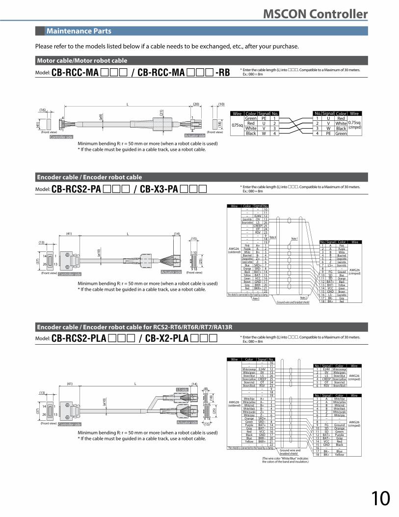
Please refer to the models listed below if a cable needs to be exchanged, etc., after your purchase.
Model: CB-RCC-MA / CB-RCC-MA -RBMotor cable/Motor robot cable
* Enter the cable length (L) into . Compatible to a Maximum of 30 meters. Ex.: 080 = 8m
* Enter the cable length (L) into . Compatible to a Maximum of 30 meters. Ex.: 080 = 8m
* Enter the cable length (L) into . Compatible to a Maximum of 30 meters. Ex.: 080 = 8m
Model: CB-RCS2-PA / CB-X3-PAEncoder cable / Encoder robot cable
Model: CB-RCS2-PLA / CB-X2-PLAEncoder cable / Encoder robot cable for RCS2-RT6/RT6R/RT7/RA13R
Minimum bending R: r = 50 mm or more (when a robot cable is used)* If the cable must be guided in a cable track, use a robot cable.
Minimum bending R: r = 50 mm or more (when a robot cable is used)* If the cable must be guided in a cable track, use a robot cable.
Maintenance Parts
10
MSCON Controller

CJ0193-1A-UST-1-0313
IAI America, Inc. IAI Industrieroboter GmbHOber der Roth 4, D-65824 Schwalbach am Taunus, GermanyHeadquarters: 2690 W. 237th Street, Torrance, CA 90505 (800) 736-1712
Chicago Office: 1261 Hamilton Parkway, Itasca, IL 60143 (800) 944-0333Atlanta Office: 1220 Kennestone Circle, Suite 108, Marietta, GA 30066 (888) 354-9470 www.intelligentactuator.comThe information contained in this product brochure may change without prior notice due to product improvements.