robotguidver21 without lines.ppt - nist ii mesa robotics, inc. packbot 510 cam, sam, eap irobot...
TRANSCRIPT
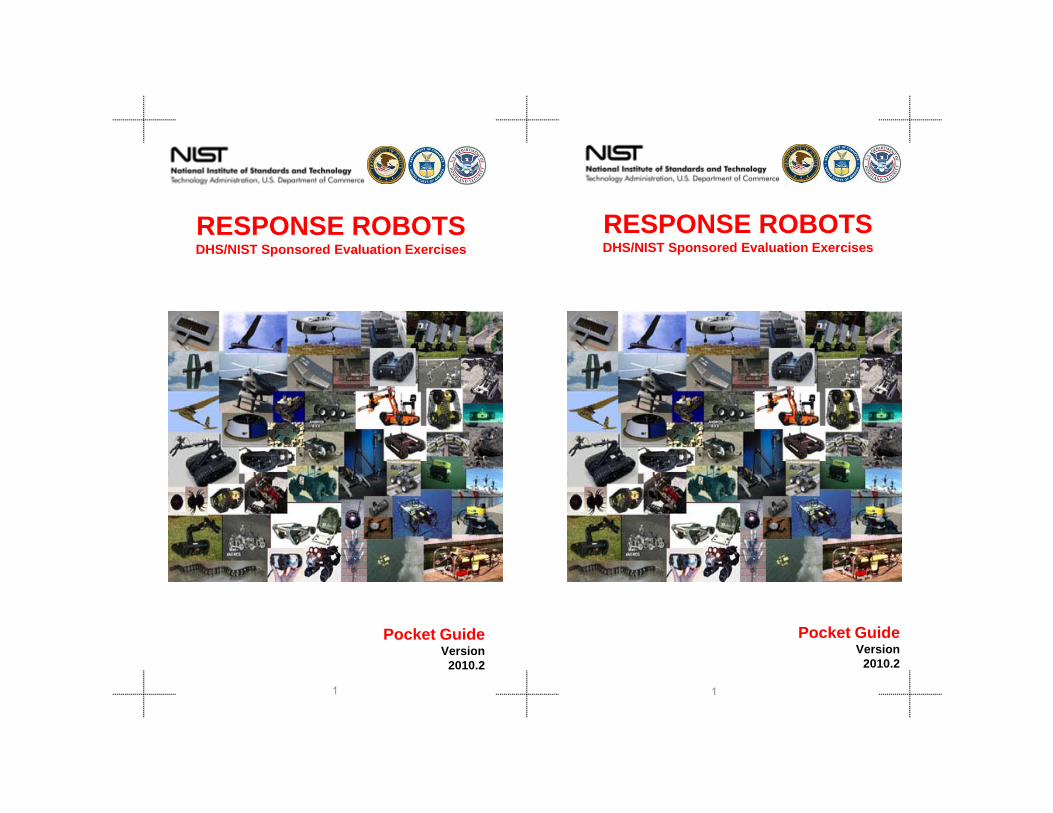
RESPONSE ROBOTSDHS/NIST Sponsored Evaluation Exercises
RESPONSE ROBOTSDHS/NIST Sponsored Evaluation Exercises
11
Pocket GuideVersion
2010.2
Pocket GuideVersion
2010.2

22
Certain commercial equipment, instruments, or materials are identified in this document. Such identification does not imply recommendation or endorsement by the National Institute of Standards and Technology, nor does it imply that the products identified are necessarily the best available for the purpose.
Certain commercial equipment, instruments, or materials are identified in this document. Such identification does not imply recommendation or endorsement by the National Institute of Standards and Technology, nor does it imply that the products identified are necessarily the best available for the purpose.
All data will be published once the test method has gone through the standards process.
All data will be published once the test method has gone through the standards process.

Adam JacoffProgram [email protected]
Albert WaveringDivision Chief
Elena MessinaGroup Leader
Ann Marie VirtsEditor/Developer
Hui-Min HuangTest Method Developer
Contacts ContactsAdam JacoffProgram [email protected]
Albert WaveringDivision Chief
Elena MessinaGroup Leader
Ann Marie VirtsEditor/Developer
Hui-Min HuangTest Method Developer
33
Intelligent Systems DivisionEngineering Laboratory
National Institute of Standards and Technology100 Bureau Drive, MS8230
Gaithersburg, MD 20899
p
Anthony DownsTest Method Developer
Futher Information:http://www.isd.mel.nist.gov/US&R_Robot_Standards/
Intelligent Systems DivisionEngineering Laboratory
National Institute of Standards and Technology100 Bureau Drive, MS8230
Gaithersburg, MD 20899
Anthony DownsTest Method Developer
Futher Information:http://www.isd.mel.nist.gov/US&R_Robot_Standards/

The Intelligent Systems Division of the National Institute of Standards and Technology is conducting an ongoing project, sponsored by the Department of Homeland Security Science and Technology Directorate and the National Institute of Justice, to produce a comprehensive set of standard test methods and associated performance metrics to quantify key capabilities of emergency response robots. These test methods address responder-defined requirements for robot mobility, manipulation, sensors, energy, communications, human-robot interfaces, logistics and safety for remotely operated ground vehicles, aquatic vehicles, and micro/mini aerial vehicles (under 2 kg/5 lbs) for urban environments. The goal is to facilitate emergency responder comparisons of different robot models based on statistically significant robot performance data captured within the standard test methods to help guide purchasing decisions and understand deployment
biliti Th t t th d l t t
Program Overview
44
capabilities. The test methods also support operator proficiency training and foster development and hardening of advanced mobile robot capabilities.
capabilities. The test methods also support operator proficiency training and foster development and hardening of advanced mobile robot capabilities.

These response robot evaluation exercises for FEMA urban search and rescue teams; federal, state and local bomb squads; and police/SWAT teams to introduce emerging robotic capabilities to emergency responders within their own training facilities, while educating robot developers regarding the necessary performance requirements and operational constraints to be effective. Emerging standard test methods and usage guides for robot performance are under development within the ASTM International Committee on Homeland Security, Operational Equipment (E54.08.01). These events help refine the proposed standard test methods and fixtures/props that developers can use to practice critical capabilities and measure performance in ways that are relevant to emergency responders. These events are conducted in US&R training scenarios to help correlate the proposed standard test methods with envisioned deployment tasks and to lay the foundation for usage guides identifying a robot's applicability to particular response scenarios.
These response robot evaluation exercises for FEMA urban search and rescue teams; federal, state and local bomb squads; and police/SWAT teams to introduce emerging robotic capabilities to emergency responders within their own training facilities, while educating robot developers regarding the necessary performance requirements and operational constraints to be effective. Emerging standard test methods and usage guides for robot performance are under development within the ASTM International Committee on Homeland Security, Operational Equipment (E54.08.01). These events help refine the proposed standard test methods and fixtures/props that developers can use to practice critical capabilities and measure performance in ways that are relevant to emergency responders. These events are conducted in US&R training scenarios to help correlate the proposed standard test methods with envisioned deployment tasks and to lay the foundation for usage guides identifying a robot's applicability to particular response scenarios.
55
TASK FORCE PARTICIPATION TASK FORCE PARTICIPATION
WAWA--TF1TF1 WAWA--TF1TF1
FLFL--TF2TF2 FLFL--TFTF22

Disaster City March 8-12, 2010
Disaster City March 8-12, 2010
66

Event IntroductionEvent IntroductionThe sixth in a series of DHS/NIST response robot evaluation exercises will be hosted at the emergency responder training facility known as Disaster City in College Station, TX. Thirty emergency responders from across the country will participate, including FEMA urban search and rescue teams; federal, state and local bomb squads; and police/SWAT teams, to help validate emerging standard robot test methods, become familiar with available robot capabilities, and advise robot developers regarding operational requirements. All applicable robots are invited to take part in this exercise including ground, aquatic, and VTOL aerials under 5 lbs. Robots will capture performance data within emerging standard test methods developed to evaluate Logistics, Mobility, Manipulation, Sensors, Radio Communications, Energy, Human-System Interaction, and Localization/Mapping capabilities. Robots may then be deployed with responders to perform operational tasks in practice scenarios, for example:•searching and mapping (2D, 3D) test methods for operational tasks in building interiors and exteriors, partially collapsed structures, and confined spaces in rubble piles •mobile manipulation test methods for operational tasks in
The sixth in a series of DHS/NIST response robot evaluation exercises will be hosted at the emergency responder training facility known as Disaster City in College Station, TX. Thirty emergency responders from across the country will participate, including FEMA urban search and rescue teams; federal, state and local bomb squads; and police/SWAT teams, to help validate emerging standard robot test methods, become familiar with available robot capabilities, and advise robot developers regarding operational requirements. All applicable robots are invited to take part in this exercise including ground, aquatic, and VTOL aerials under 5 lbs. Robots will capture performance data within emerging standard test methods developed to evaluate Logistics, Mobility, Manipulation, Sensors, Radio Communications, Energy, Human-System Interaction, and Localization/Mapping capabilities. Robots may then be deployed with responders to perform operational tasks in practice scenarios, for example:•searching and mapping (2D, 3D) test methods for operational tasks in building interiors and exteriors, partially collapsed structures, and confined spaces in rubble piles •mobile manipulation test methods for operational tasks in
77
•mobile manipulation test methods for operational tasks in EOD scenarios•endurance, radio communications, sensor acuity, and decontamination/washdown test methods for operational tasks in down-range reconnaissance of a hazardous materials train wreck from an stand-off greater than 150m/500ft•towing test methods (trailers, gripper-drag) for operational tasks in EOD and US&R scenarios•underwater test methods for navigation and sensor acuity for operational tasks in the on-sight pond•aerial test methods for air-worthiness, station-keeping, and sensor acuity for operational tasks supporting scenarios noted above
–
EOD scenarios•endurance, radio communications, sensor acuity, and decontamination/washdown test methods for operational tasks in down-range reconnaissance of a hazardous materials train wreck from an stand-off greater than 150m/500ft•towing test methods (trailers, gripper-drag) for operational tasks in EOD and US&R scenarios•underwater test methods for navigation and sensor acuity for operational tasks in the on-sight pond•aerial test methods for air-worthiness, station-keeping, and sensor acuity for operational tasks supporting scenarios noted above
–

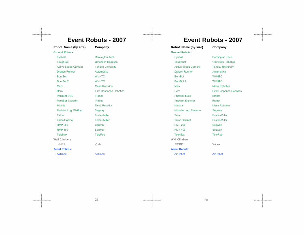
Event Robots - 2010 Event Robots - 2010Robot Name (by size) CompanyGround Robots
Scout ReconRobotics, Inc.
ActiveScopeCamera Tohoku University
Pointman Applied Research Associates, Inc.
VGTV-Extreme Inuktun
Dragon Runner Qinetiq N. America / Foster-Miller Inc.
Versatrax Inuktun
Souryu IV International Rescue Systems Institute
G2Bot Mesa Robotics, Inc.
Element Mesa Robotics, Inc.
UMRS 2009 International Rescue Systems Institute
Kenaf International Rescue Systems Institute
Quince International Rescue Systems Institute
Digital Vanguard ROV Allen Vanguard Corp.
Robot Name (by size) CompanyGround Robots
Scout ReconRobotics, Inc.
ActiveScopeCamera Tohoku University
Pointman Applied Research Associates, Inc.
VGTV-Extreme Inuktun
Dragon Runner Qinetiq N. America / Foster-Miller Inc.
Versatrax Inuktun
Souryu IV International Rescue Systems Institute
G2Bot Mesa Robotics, Inc.
Element Mesa Robotics, Inc.
UMRS 2009 International Rescue Systems Institute
Kenaf International Rescue Systems Institute
Quince International Rescue Systems Institute
Digital Vanguard ROV Allen Vanguard Corp.
88
Matilda II Mesa Robotics, Inc.
PackBot 510 CAM, SAM, EAP iRobot Corp.
NuTech-R4 Nagaoka University of Technology
Helios IX International Rescue Systems Institute
KOHGA International Rescue Systems Institute
Talon GenIV Qinetiq N. America / Foster-Miller Inc.
Talon GenIV Hazmat Qinetiq N. America / Foster-Miller Inc.
Talon GenIV Shoulder Qinetiq N. America / Foster-Miller Inc.
TeleMAX Telerob, GmbH
Caliber MK3 EOD ICOR Technologies
Andros HD-1J Northrop Grumman Remotec
Andros Mini Northrop Grumman Remotec
RMP 400-INL Segway, Inc.
Centaur The MITRE Corporation

Event Robots - 2010 Event Robots - 2010Robot Name (by size) CompanyAerial Robots
sUAS VTOL (FAA ARC Group I under 2kg, 30knots, frangible)
AirRobot AirRobot GmbH
Aquatic Robots
LBV200L2 SeaBotix
LBV150SE-5 SeaBotix
Robot Name (by size) CompanyAerial Robots
sUAS VTOL (FAA ARC Group I under 2kg, 30knots, frangible)
AirRobot AirRobot GmbH
Aquatic Robots
LBV200L2 SeaBotix
LBV150SE-5 SeaBotix
99

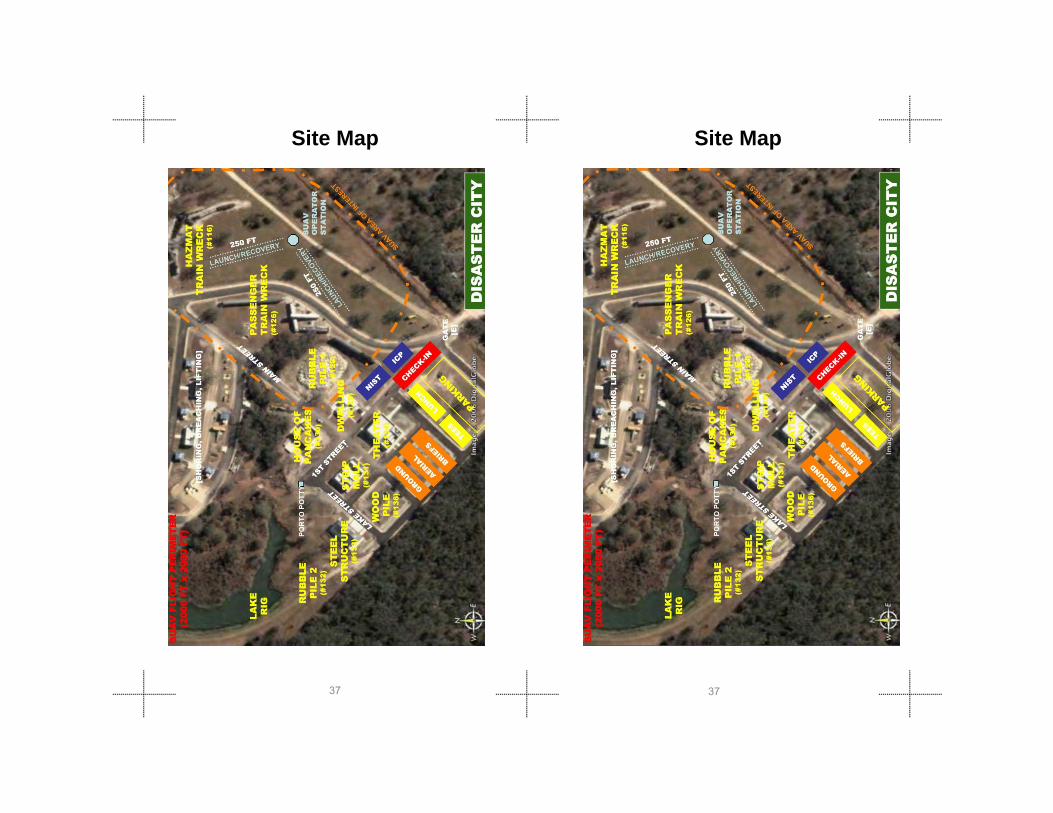
Site Map Site Map
1010

#134Multi-Purpose Building
Collapse/Theater Building
#134Multi-Purpose Building
Collapse/Theater Building
1111
Dispatch Station/Robot Picture/Cache Packaging
Robot Navigation During Teleoperation ( Random Maze)
Dispatch Station/Robot Picture/Cache Packaging
Robot Navigation During Teleoperation ( Random Maze)

Main Street
Visual Acuity/Field Of View/Spatial Awareness Test Method
#130 Annex
Main Street
Visual Acuity/Field Of View/Spatial Awareness Test Method
#130 Annex
1212
Covered Vehicle Port
Endurance Test Method Endurance Test Method
Covered Vehicle Port

#130
#129Dwelling Collapse
The House of Pancakes collapse scenario
#130
#129Dwelling Collapse
The House of Pancakes collapse scenario
1313
#130House of Pancakes
Dwelling collapse scenario
#130House of Pancakes
Dwelling collapse scenario

#133Municipal BuildingIndustrial Complex
Confined Space Test Method Incline Plane Test Method
#133Municipal BuildingIndustrial Complex
Confined Space Test Method Incline Plane Test Method
1414
Stairs
Step Gap Test Method
Stairs
Step Gap Test Method

#131Strip Mall Collapse
Directed Perception and Grasping Dexterity Test Method
#131Strip Mall Collapse
Directed Perception and Grasping Dexterity Test Method
Near Hazmat Train Derailment Near Hazmat Train Derailment
1515
Near Hazmat Train Derailment Near Hazmat Train Derailment
Towing Test Method Towing Test Method

Hazmat Train Derailment Hazmat Train Derailment
1616
#128Passenger Train
Derailment
Passenger train derailment scenario
#128Passenger Train
Derailment
Passenger train derailment scenario
Decontamination Test MethodDecontamination Test Method

Lake / Dock Lake / Dock
1717
Underwater Scenario Underwater Scenario

Off-SiteRiverside Airstrip
Off-SiteRiverside Airstrip
1818
Radio Comms Non-line of Sight Test Method Radio Comms Non-line of Sight Test Method
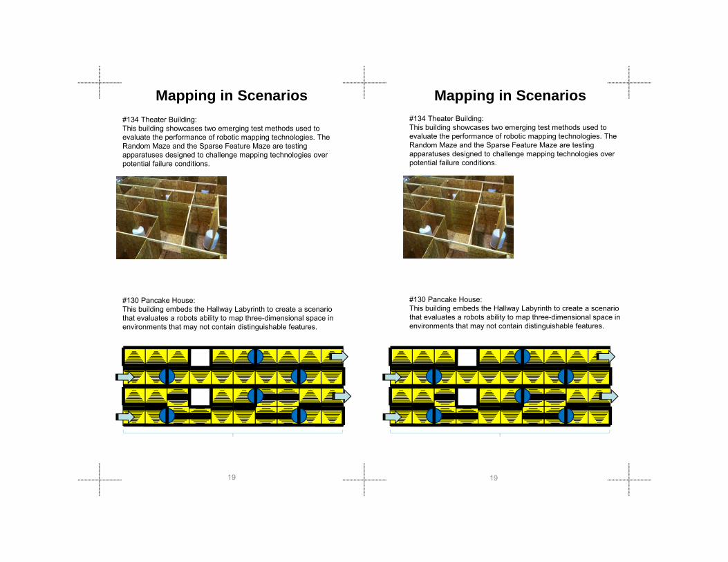
Mapping in Scenarios#134 Theater Building: This building showcases two emerging test methods used to evaluate the performance of robotic mapping technologies. The Random Maze and the Sparse Feature Maze are testing apparatuses designed to challenge mapping technologies over potential failure conditions.
Mapping in Scenarios#134 Theater Building: This building showcases two emerging test methods used to evaluate the performance of robotic mapping technologies. The Random Maze and the Sparse Feature Maze are testing apparatuses designed to challenge mapping technologies over potential failure conditions.
1919
#130 Pancake House:This building embeds the Hallway Labyrinth to create a scenario that evaluates a robots ability to map three-dimensional space in environments that may not contain distinguishable features.
#130 Pancake House:This building embeds the Hallway Labyrinth to create a scenario that evaluates a robots ability to map three-dimensional space in environments that may not contain distinguishable features.

Mapping in Scenarios Cont. Mapping in Scenarios Cont.
#128 Passenger Train DerailmentThe scenario combines emerging test methods used to evaluate the mobility of robotic platforms to assess how complex terrain in variable environmental conditions (indoor and outdoor) will impact the ability of a robot to make maps
Passenger Train Derailment Inside Passenger Train Passenger Train Derailment Inside Passenger Train
#128 Passenger Train DerailmentThe scenario combines emerging test methods used to evaluate the mobility of robotic platforms to assess how complex terrain in variable environmental conditions (indoor and outdoor) will impact the ability of a robot to make maps
2020
#129 The Dwelling:This building houses partial mazes in operationally relevant environments to create a scenario that explores the ability of a robot to create maps in unknown environments.
The Dwelling Partial Mazes in Scenario The Dwelling Partial Mazes in Scenarios
#129 The Dwelling:This building houses partial mazes in operationally relevant environments to create a scenario that explores the ability of a robot to create maps in unknown environments.

2121
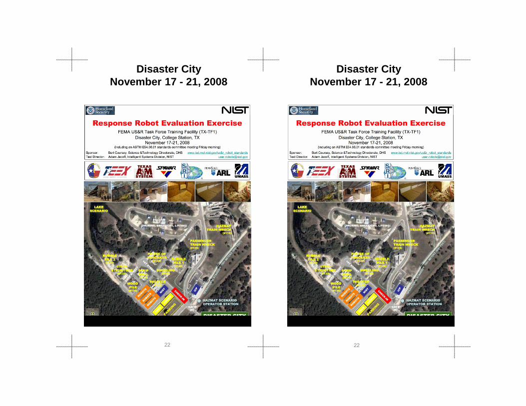
Disaster City November 17 - 21, 2008
Disaster City November 17 - 21, 2008
2222

Event IntroductionEvent IntroductionThe fifth in a series of DHS/NIST Response Robot Evaluation Exercises for FEMA urban search and rescue (US&R) teams is hosted at the Texas Task Force 1 (TX-TF1) training facility known as Disaster City located at Texas A&M University, College Station, TX. All applicable robots were invited to take part in this exercise, which will capture robot performance data within emerging standard robot test methods and operationally relevant practice scenarios. Practice scenarios feature ground robots working in confined spaces within a partially collapsed structure along with down-range reconnaissance of two train wrecks; one a hazardous materials train and the other a passenger train from an operational stand-off greater than 150m/500ft. Other practice scenarios will also be available.
The robots used in these scenarios should deploy any or all appropriate sensors such as: color cameras, two-way audio, thermal imagers, chemical sensors, 3D mapping, GPS/GIS location, and/or other useful capabilities such as payloads, manipulators, etc. General descriptions of the robots that were sought are as follows, but are not limited
The fifth in a series of DHS/NIST Response Robot Evaluation Exercises for FEMA urban search and rescue (US&R) teams is hosted at the Texas Task Force 1 (TX-TF1) training facility known as Disaster City located at Texas A&M University, College Station, TX. All applicable robots were invited to take part in this exercise, which will capture robot performance data within emerging standard robot test methods and operationally relevant practice scenarios. Practice scenarios feature ground robots working in confined spaces within a partially collapsed structure along with down-range reconnaissance of two train wrecks; one a hazardous materials train and the other a passenger train from an operational stand-off greater than 150m/500ft. Other practice scenarios will also be available.
The robots used in these scenarios should deploy any or all appropriate sensors such as: color cameras, two-way audio, thermal imagers, chemical sensors, 3D mapping, GPS/GIS location, and/or other useful capabilities such as payloads, manipulators, etc. General descriptions of the robots that were sought are as follows, but are not limited
2323
g ,to:
– Ground based portable robots that can circumnavigate large unknown situations
– Highly agile, man-packable robots that can lead responders through complex environments
– Confined space accessible robots for deployment into sub-human size voids or be thrown into/over inaccessible area
– Aquatic vehicles with sonar and/or other sensors to search and identify underwater environments
– Quad-rotor aerial vehicles (under 2kg/4.4lbs) deploying sensors to perform horizontal and vertical station keeping in front of windows.

Event Robots - 2008 Event Robots - 2008Robot Name (by size) CompanyGround Robots
Active Scope Camera Tohoku University
Pointman (LRV) ARA
VGTV Inuktun
Dragon Runner SUGV Foster-Miller/Automatika
Versatrax 100 Inuktun
Marv Mesa Robotics
G2Bot Mesa Robotics
Jacobs Rugg.Robot Jacobs University
Hero First-Response Robotics
Super Kenaf IRS
PackBot EOD iRobot
PackBot Explorer iRobot
R bbi 6 U i it K bl L d
Robot Name (by size) CompanyGround Robots
Active Scope Camera Tohoku University
Pointman (LRV) ARA
VGTV Inuktun
Dragon Runner SUGV Foster-Miller/Automatika
Versatrax 100 Inuktun
Marv Mesa Robotics
G2Bot Mesa Robotics
Jacobs Rugg.Robot Jacobs University
Hero First-Response Robotics
Super Kenaf IRS
PackBot EOD iRobot
PackBot Explorer iRobot
R bbi 6 U i it K bl L d
2424
Robbie 6 University Koblenz-Landau
Matilda Mesa Robotics
Matilda II Mesa Robotics
NuTech-R4 Nagaoka Univ. Tech.
Versatrax 150 Inuktun
Modular Log. Platform Segway
Talon Gen IV Foster-Miller/Qinetiq
Talon Hazmat Foster-Miller/Qinetiq
TeleMAX TeleRob
HD-1 Remotec
RMP 400 Segway
Aerial Robots
AirRobot AirRobot

Event Robots - 2008 Event Robots - 2008Robot Name (by size) CompanyAquatic Robots
VideoRay Pro 3 VideoRay
LBV200L2 SeaBotix
LBV150SE-5 SeaBotix
Sensors
dcMap University of Freiburg
High Speed 3D Scanner Tohoku University
Multibeam Imaging Sonar
MBI350-45 BlueView Tech.
P450E-15 BlueView Tech.
P900E-20 BlueView Tech.
Multibeam Imaging Sonar BlueView Tech.
Swiss Ranger 4000 Mesa Imaging
Robot Name (by size) CompanyAquatic Robots
VideoRay Pro 3 VideoRay
LBV200L2 SeaBotix
LBV150SE-5 SeaBotix
Sensors
dcMap University of Freiburg
High Speed 3D Scanner Tohoku University
Multibeam Imaging Sonar
MBI350-45 BlueView Tech.
P450E-15 BlueView Tech.
P900E-20 BlueView Tech.
Multibeam Imaging Sonar BlueView Tech.
Swiss Ranger 4000 Mesa Imaging
2525

Disaster City June 18-22, 2007
Disaster City June 18-22, 2007
2626

Event IntroductionEvent IntroductionThe fourth in a series of DHS/NIST Response Robot Evaluation Exercises for FEMA urban search and rescue (US&R) teams is hosted at the Texas Task Force 1 (TX-TF1) training facility known as Disaster City located at Texas A&M University, College Station, TX. All applicable robots were invited to take part in this exercise, which will capture robot performance data within emerging standard robot test methods and operationally relevant practice scenarios. Practice scenarios feature ground robots working in confined spaces within a partially collapsed structure along with down-range reconnaissance of two train wrecks; one a hazardous materials train and the other a passenger train from an operational stand-off greater than 150m/500ft. Other practice scenarios will also be available.
The robots used in these scenarios should deploy any or all appropriate sensors such as: color cameras, two-way audio, thermal imagers, chemical sensors, 3D mapping, GPS/GIS location, and/or other useful capabilities such as payloads, manipulators, etc. General descriptions of the robots that were sought are as follows, but are not limited to:
– Ground based portable robots that can circumnavigate large unknown situations (i.e. around the train derailments).Highly agile man packable robots that can lead
The fourth in a series of DHS/NIST Response Robot Evaluation Exercises for FEMA urban search and rescue (US&R) teams is hosted at the Texas Task Force 1 (TX-TF1) training facility known as Disaster City located at Texas A&M University, College Station, TX. All applicable robots were invited to take part in this exercise, which will capture robot performance data within emerging standard robot test methods and operationally relevant practice scenarios. Practice scenarios feature ground robots working in confined spaces within a partially collapsed structure along with down-range reconnaissance of two train wrecks; one a hazardous materials train and the other a passenger train from an operational stand-off greater than 150m/500ft. Other practice scenarios will also be available.
The robots used in these scenarios should deploy any or all appropriate sensors such as: color cameras, two-way audio, thermal imagers, chemical sensors, 3D mapping, GPS/GIS location, and/or other useful capabilities such as payloads, manipulators, etc. General descriptions of the robots that were sought are as follows, but are not limited to:
– Ground based portable robots that can circumnavigate large unknown situations (i.e. around the train derailments).Highly agile man packable robots that can lead
2727
– Highly agile, man-packable robots that can lead responders through complex environments (i.e. the buildings and rubble piles).
– Confined space accessible robots for deployment into sub-human size voids or be thrown into/over inaccessible area
– Wall climbing robots for surveillance from elevated vantage points
Event Robots - 2007 Event Robots - 2007Robot Name (by size) CompanyGround Robots
Eyeball Remington Tech
ToughBot Omnitech Robotics
Active Scope Camera Tohoku University
Dragon Runner Automatika
BomBot WVHTC
BomBot 2 WVHTC
Marv Mesa Robotics
Hero First-Response Robotics
PackBot EOD iRobot
PackBot Explorer iRobot
Matilda Mesa Robotics
Modular Log. Platform Segway
Talon Foster-Miller
Robot Name (by size) CompanyGround Robots
Eyeball Remington Tech
ToughBot Omnitech Robotics
Active Scope Camera Tohoku University
Dragon Runner Automatika
BomBot WVHTC
BomBot 2 WVHTC
Marv Mesa Robotics
Hero First-Response Robotics
PackBot EOD iRobot
PackBot Explorer iRobot
Matilda Mesa Robotics
Modular Log. Platform Segway
Talon Foster-Miller
2828
Talon Hazmat Foster-Miller
RMP 200 Segway
RMP 400 Segway
TeleMax TeleRob
Wall Climbers
VMRP Vortex
Aerial Robots
AirRobot AirRobot
Talon Hazmat Foster-Miller
RMP 200 Segway
RMP 400 Segway
TeleMax TeleRob
Wall Climbers
VMRP Vortex
Aerial Robots
AirRobot AirRobot

Site Map Site Map
2929
Maryland TF-1 August 19-21, 2006
Maryland TF-1 August 19-21, 2006
3030

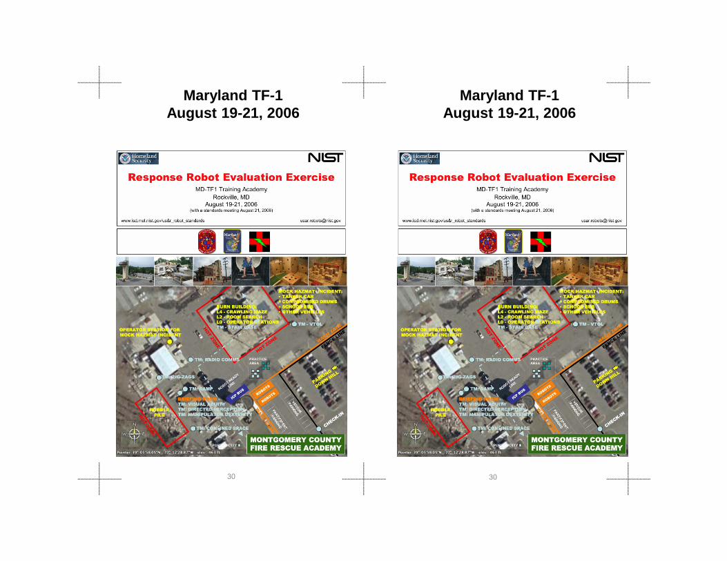
The third in a series of response robot informal evaluation exercises for DHS/FEMA US&R teams was hosted at the Montgomery County Fire Rescue Training Academy in Rockville, Maryland (near Washington DC). This event finalized the test methods targeted for the initial (Wave 1) set of standards as well as initiated experimentation with onboard payloads, especially for Chemical, Biological, Radiological, Nuclear, and Explosive (CBRNE) sensing. Therefore, emphasis was on (a) robots that could address the deployment categories relevant to Wave 1 standards and (b) deploying CBRNE sensors on these robots. The three robot deployment categories selected by responders to be emphasized in Wave 1 are: ground peek robots that are small and throwable, ground wide-area survey robots that can traverse non-collapsed structures or areas external to the collapse, and aerial survey or loiter robots. Manufacturers of robots, purchasable and/or developmental, that can address these areas, were invited to take part in this exercise, which will highlight operationally relevant US&R scenarios.
Maryland Task Force 1 Training Facility
Event IntroductionThe third in a series of response robot informal evaluation exercises for DHS/FEMA US&R teams was hosted at the Montgomery County Fire Rescue Training Academy in Rockville, Maryland (near Washington DC). This event finalized the test methods targeted for the initial (Wave 1) set of standards as well as initiated experimentation with onboard payloads, especially for Chemical, Biological, Radiological, Nuclear, and Explosive (CBRNE) sensing. Therefore, emphasis was on (a) robots that could address the deployment categories relevant to Wave 1 standards and (b) deploying CBRNE sensors on these robots. The three robot deployment categories selected by responders to be emphasized in Wave 1 are: ground peek robots that are small and throwable, ground wide-area survey robots that can traverse non-collapsed structures or areas external to the collapse, and aerial survey or loiter robots. Manufacturers of robots, purchasable and/or developmental, that can address these areas, were invited to take part in this exercise, which will highlight operationally relevant US&R scenarios.Maryland Task Force 1 Training Facility
Event Introduction
3131
Maryland Task Force 1 Training Facility Maryland Task Force 1 Training Facility

Event Robots - 2006 Event Robots - 2006Robot Name (by size) CompanyGround Robots
Eyeball Remington Tech
ToughBot Omnitech Robotics
Iris Toin
LRV Applied Research Assoc.
VGTV-Extreme Inuktun
Dragon Runner Automatika
BomBot WVHTC
Marv Mesa Robotics
Soryu IRS
Soryu V IRS
PackBot EOD iRobot
PackBot Explorer iRobot
Hibiscus Toin
Cphea Toin
Robot Name (by size) CompanyGround Robots
Eyeball Remington Tech
ToughBot Omnitech Robotics
Iris Toin
LRV Applied Research Assoc.
VGTV-Extreme Inuktun
Dragon Runner Automatika
BomBot WVHTC
Marv Mesa Robotics
Soryu IRS
Soryu V IRS
PackBot EOD iRobot
PackBot Explorer iRobot
Hibiscus Toin
Cphea Toin
3232
Shinobi Univer. Electro Comm.
Matilda Mesa Robotics
ATRV mini Idaho National Lab
Talon Foster-Miller
Mini-Andros II Remotec
Andros F6A Remotec
Boz I BOZ Robotics
Wall ClimbersVMRP Vortex
NanoMag Inuktun
Aerial RobotsBlimp ARACAR
AirRobot AirRobot
Yamaha Heliocoper Skeyes Unlimited
Shinobi Univer. Electro Comm.
Matilda Mesa Robotics
ATRV mini Idaho National Lab
Talon Foster-Miller
Mini-Andros II Remotec
Andros F6A Remotec
Boz I BOZ Robotics
Wall ClimbersVMRP Vortex
NanoMag Inuktun
Aerial RobotsBlimp ARACAR
AirRobot AirRobot
Yamaha Heliocoper Skeyes Unlimited

Site OverviewSite Overview
3333
Disaster City April 4-6, 2006
Disaster City April 4-6, 2006
3434

Event Introduction Event Introduction
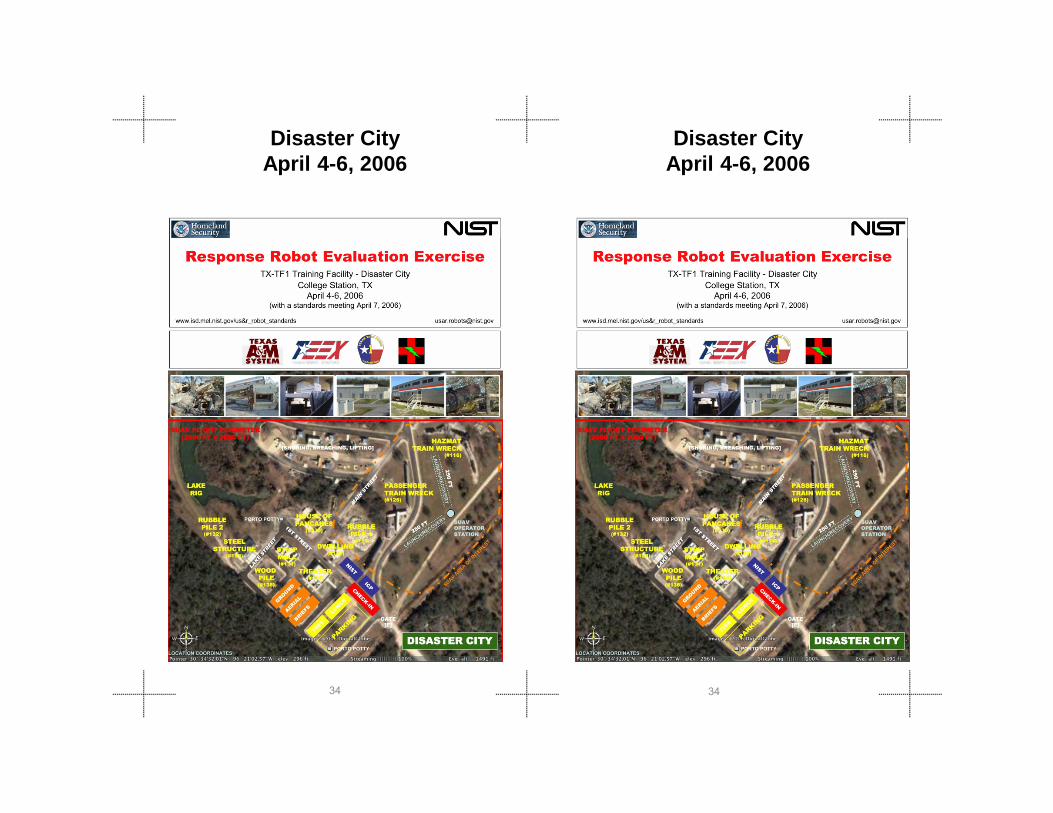
The second in a series of response robot evaluation exercises for DHS/FEMA US&R teams was hosted at the TX-TF1 training facility known as Disaster City located at Texas A&M University, College Station, TX. All applicable robots and supporting technologies (e.g., sensors), purchasable and/or developmental, were invited to take part in this exercise, which highlighted operationally relevant US&R scenarios specifically devised for ground, aerial, and underwater response robots. Based on their experiences deploying robots within the training scenarios, responders selected three robot categories as being the focus deployment types for the development of the Wave 1 standards. These are small throw-able "peek bots;" wide-area ground survey robots; and aerial loiter/survey robots.
The second in a series of response robot evaluation exercises for DHS/FEMA US&R teams was hosted at the TX-TF1 training facility known as Disaster City located at Texas A&M University, College Station, TX. All applicable robots and supporting technologies (e.g., sensors), purchasable and/or developmental, were invited to take part in this exercise, which highlighted operationally relevant US&R scenarios specifically devised for ground, aerial, and underwater response robots. Based on their experiences deploying robots within the training scenarios, responders selected three robot categories as being the focus deployment types for the development of the Wave 1 standards. These are small throw-able "peek bots;" wide-area ground survey robots; and aerial loiter/survey robots.
3535

Event Robots - 2006 Event Robots - 2006Robot Name (by size) CompanyGround Robots
Eyeball Remington Tech
ToughBot Omnitech Robotics
VGTV-Extreme Inuktun
BomBot WVHTC
Marv Mesa Robotics
PackBot EOD iRobot
PackBot Explorer iRobot
Matilda Mesa Robotics
Chaos Autonomous Solutions, Inc.
Talon Foster-Miller
Mini-Andros II Remotec
Andros F6A Remotec
TeleMax TeleRob
PackBot Scout iRobot
Robot Name (by size) CompanyGround Robots
Eyeball Remington Tech
ToughBot Omnitech Robotics
VGTV-Extreme Inuktun
BomBot WVHTC
Marv Mesa Robotics
PackBot EOD iRobot
PackBot Explorer iRobot
Matilda Mesa Robotics
Chaos Autonomous Solutions, Inc.
Talon Foster-Miller
Mini-Andros II Remotec
Andros F6A Remotec
TeleMax TeleRob
PackBot Scout iRobot
3636
PackBot Scout iRobot
Sneaky M-Bots
Wall Climbers
VMRP Vortex
NanoMag Inuktun
Aerial Robots
Blimp ARACAR
Nighthawk Applied Research Assoc.
Dragon Eye AeroVironment, Inc.
CyberBug Cyber Defense Systems, Inc.
Raven AeroVironment, Inc.
Evolution-XTS L-3 BAI Aerosystems, Inc
Flying Bassett Univ. of AL – Huntsville
Wasp AeroVironment, Inc.
Aquatic Robots
Pro III VideoRay, LLC
Site Map Site Map
3737

3838
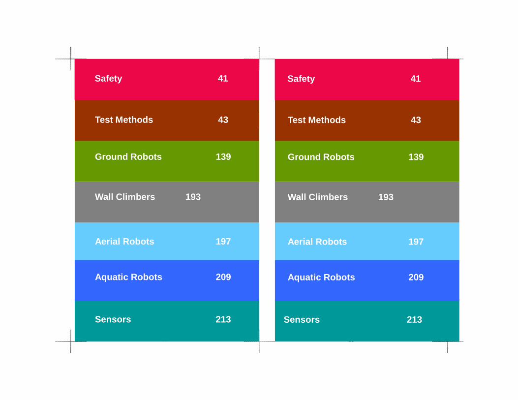
Ground Robots 139
Wall Climbers 193
Test Methods 43
Safety 41
Ground Robots 139
Wall Climbers 193
Test Methods 43
Safety 41
3939
Sensors 213
Aerial Robots 197
Aquatic Robots 209
Sensors 213
a C be s 93
Aerial Robots 197
Aquatic Robots 209

4040
Safety
• Appropriate personal protective equipment (PPE) must be worn at all times while on site (see associated page on PPE). Compliance with PPE rules are mandatory.
• Rubble piles and other difficult scenarios present the most risk to novices. If your robot needs to be extracted, please ask your associated emergency responder to retrieve it.
• Always maintain awareness of others working within your scenario and communicate your intentions *before* doing whatever you have in mind.
Safety of all personnel participating in this event is our first concern. The fact that we have robotics personnel generally unaccustomed to working within the hazardous environments at these US&R training sites is particularly problematic. Having emergency responders generally unaccustomed to working with robots is also a concern. Please follow these simple guidelines:
Safe
ty
4141
• Robots can do unpredictable things; the bigger/heavier the robot the more space you should allow it when operating. Always verify that the robot is powered off before interacting with it. Never stick your fingers into wheels, tracks, manipulator pinch points, etc. while the robot is powered on. Remotely teleoperated robots may be the most dangerous because the remote operator may not know you decided to perform on-the-spot maintenance! Always familiarize yourself with the EMERGENCY STOP procedures first -- and last --before interacting with or operating robots. Some implementations are more predictable than others.
• If you see anything you consider unsafe in our environment, please inform the Test Director or any emergency responder on site, and let’s discuss it at the daily after action briefing to be sure every potential hazard is addressed.
• Everybody on site is a safety officer!

Personal Protective Equipment
• Helmet Hard hats are okay. We have some to borrow or you can purchase at www.thefirestore.com for $75 and up.
• Ear protectionWe'll supply these
Personal Protective Equipment
Personal protective equipment (PPE) is required for working within any US&R scenario at the site. People in street clothes or without helmets/gloves/etc as shown below are limited to paved roads only. If you are working within a scenario, you must wear ALL the equipment shown below. Compliance with these personal protective equipment rules are mandatory - it is standard practice for US&R environments.
• Helmet Hard hats are okay. We have some to borrow or you can purchase at www.thefirestore.com for $75 and up.
• Ear protectionWe'll supply these
Personal protective equipment (PPE) is required for working within any US&R scenario at the site. People in street clothes or without helmets/gloves/etc as shown below are limited to paved roads only. If you are working within a scenario, you must wear ALL the equipment shown below. Compliance with these personal protective equipment rules are mandatory - it is standard practice for US&R environments.
4242
We ll supply these.
• Eye protectionSunglasses are okay.
• Long sleeve shirt
• Work gloves
• Long pantsArmy surplus stores sell typical BDU and EMT pants.
• BootsPreferably steel toe.
Additional protective padding for knees and elbows is optional, but good for rubble piles.
We ll supply these.
• Eye protectionSunglasses are okay.
• Long sleeve shirt
• Work gloves
• Long pantsArmy surplus stores sell typical BDU and EMT pants.
• BootsPreferably steel toe.
Additional protective padding for knees and elbows is optional, but good for rubble piles.

Test
M
etho
ds
Test
M
etho
ds
Test Methods Test Methods
4343

Status Indicators:Standard (ASTM ####-##), Validating (V), Prototyping (P)
Standard Terminology for Emergency Response Robots (ASTM E2521-07A)
Standard Practice for Establishing the Test Configuration and Associated Cache Packaged Weight and Volume of Emergency Response Robots (ASTM E2592-07)
Energy/Power• Endurance Tasks: Terrains: Continuous Pitch/Roll
Ramps (V)
Mobility• Terrains: Flat/Paved Surfaces (V)• Terrains: Continuous Pitch/Roll Ramps (V)• Terrains: Crossing Pitch/Roll Ramps (V)• Terrains: Symmetric Stepfields (V)• Terrains: Sand (P)
4444
• Terrains: Gravel (P)• Terrains: Mud (P)• Obstacles: Inclined Planes (V)• Obstacles: Gap Crossings: Static, Dynamic (V)• Obstacles: Pipe Steps (V)• Obstacles: Stair/Landings (V)• Obstacles: Confined Space (P)• Towing: Grasped Sleds (V)• Towing: Hitched Sleds (P) • Towing: Hitched Trailers (P)
Radio Communications• Control and Perception Tasks: Line-of-Sight (V)• Control and Perception Tasks: Non-Line-of-Sight (V)• Control and Perception Tasks: Structure Penetration (P)

Test
M
etho
ds
Test
M
etho
ds
Manipulation• Directed Perception Tasks: Open Access (V) • Directed Perception Tasks: Reach-Over Access (P)• Directed Perception Tasks: Reach-Under Access (P)• Gasping Dexterity Tasks : Open Access (V)• Gasping Dexterity Tasks : Reach-Over Access (P)• Gasping Dexterity Tasks : Reach-Under Access (P)• Gasping Dexterity Tasks : Weighted Payloads (P)• Door Opening and Traversal Tasks (V)
Human-System Interaction• Navigation Tasks: Random Mazes with Complex Terrain (V) • Navigation Tasks: Outdoor Navigation for Large UGV (P)• Search Tasks: Random Mazes with Complex Terrain (V) • Search Tasks: Under-Body Voids with Complex Terrain (V) • Operator Interface Constraints: PPE; Posture; Lighting (P)• Operator Interface Indicators: Low Battery; Robot Tilt (P)
Sensor
4545
Sensor• Video Acuity Charts/Field of View Measures (ASTM
E2566-08)• Video Directed Search Tasks: Detailed (V) • Video Directed Search Tasks: Rapid (P) • Audio Speech Intelligibility Rhyming Words (2-Way) (V)
• Audio Spectrum Response Tones (P)• Ranging Targets and Spatial Resolution Measures (P)• Localization/Mapping Tasks: Hallway Labyrinths with
Complex Terrain (P)• Localization/Mapping Tasks: Wall Mazes with Complex
Terrain (P)• Localization and Mapping Tasks: Sparse Feature
Environments (P)• Localization and Mapping Tasks: Tunnel Mazes (P)

Washdown/Decontamination Capabilities of Emergency Response Robots (V)
Aerial • sUAS (Group I) VTOL Endurance• sUAS (Group I) VTOL Station-Keeping
Operational Task: Radio Comms: Nike Siite
Operational Task: Metrobus Package Removal/Disruption
Operational Task: sUAS (Group I) VTOL Exterior Building Reconnaissance
4646

Test
M
etho
ds
Test
M
etho
ds
4747

Development ProcessThe process used to develop standard test methods begins with specific requirements defined by emergency responders for robotic capabilities that could make their operational deployments more effective, efficient, or safe. Each requirement must have an associated metric along with thresholds of performance below which the responders will not accept. Where such robot requirements already exist, for example bomb squad applications, they may have been used directly. Other responder communities, for example technical search specialists from FEMA urban search and rescue teams, were solicited during the course of this program and have provided over 100 such requirements for 13 different categories of robots.
Development ProcessThe process used to develop standard test methods begins with specific requirements defined by emergency responders for robotic capabilities that could make their operational deployments more effective, efficient, or safe. Each requirement must have an associated metric along with thresholds of performance below which the responders will not accept. Where such robot requirements already exist, for example bomb squad applications, they may have been used directly. Other responder communities, for example technical search specialists from FEMA urban search and rescue teams, were solicited during the course of this program and have provided over 100 such requirements for 13 different categories of robots.
4848
The requirements are prioritized by responders and prototype test apparatuses are generated to isolate and repeatably test and measure robot performance. Response robot evaluation exercises are hosted in responder training facilities to allow responders to validate the test methods and learn about emerging robotic capabilities. International robot competitions featuring the prototype test apparatuses and tasks are used to leverage robot traffic (over 100 missions per competition) to refine apparatus designs and inspire robot innovations. They also support proliferation of the test methods for practice and provide benchmark comparisons for qualification. Once the apparatus is validated, it is balloted through the ASTM Standards Committee on Homeland Security Applications; Operational Equipment; Robots (E54.08.01).
The requirements are prioritized by responders and prototype test apparatuses are generated to isolate and repeatably test and measure robot performance. Response robot evaluation exercises are hosted in responder training facilities to allow responders to validate the test methods and learn about emerging robotic capabilities. International robot competitions featuring the prototype test apparatuses and tasks are used to leverage robot traffic (over 100 missions per competition) to refine apparatus designs and inspire robot innovations. They also support proliferation of the test methods for practice and provide benchmark comparisons for qualification. Once the apparatus is validated, it is balloted through the ASTM Standards Committee on Homeland Security Applications; Operational Equipment; Robots (E54.08.01).

Test
M
etho
ds
Test
M
etho
ds
General ScopeThis suite of test methods characterize the capabilities of robots intended to operate in human-scale, complex environments with variable terrains, lighting, temperature, etc. Robots under test shall be teleoperated via a remote operator control unit (OCU), out of sight and sound of the test apparatuses but within communications range (except for the radio communications test methods). The robot configuration as tested shall be specified in detail (manipulators, payloads, batteries, communications, etc) and subjected to the entire suite of test methods. Any variation in robot configuration must be retested across the entire suite of test methods to provide a comprehensive overview of performance characteristics for that particular robot variant. Systems with assistive capabilities or autonomous behaviors should demonstrate improved remote operator/robot performance, efficiency, or survivability of the robot under test. Although these test methods were developed specifically for emergency response robots, they may be applicable to other application domains with modest variations in terrains, targets, or tasks.
A B C D
General ScopeThis suite of test methods characterize the capabilities of robots intended to operate in human-scale, complex environments with variable terrains, lighting, temperature, etc. Robots under test shall be teleoperated via a remote operator control unit (OCU), out of sight and sound of the test apparatuses but within communications range (except for the radio communications test methods). The robot configuration as tested shall be specified in detail (manipulators, payloads, batteries, communications, etc) and subjected to the entire suite of test methods. Any variation inrobot configuration must be retested across the entire suite oftest methods to provide a comprehensive overview of performance characteristics for that particular robot variant. Systems with assistive capabilities or autonomous behaviors should demonstrate improved remote operator/robot performance, efficiency, or survivability of the robot under test. Although these test methods were developed specifically for emergency response robots, they may be applicable to other application domains with modest variations in terrains, targets, or tasks.
A B C D
4949
A B C D
E F G H
Robots shown above are typical of the size robot these test methods are intended to evaluate. They are shown in front of a 20 cm (8 inch) metered backdrop used in the Standard Practice for Establishing the Test Configuration and Associated Cache Packaged Weight and Volume of Emergency Response Robots. These eight robots provided the first ten robot configurations to be subjected to the entire suite of emerging standard test methods to determine test method “repeatability” within a single apparatus and test method “reproducibility” across different test facilities. Two of the robots also tested either without their manipulator or with an extended manipulator making them new configuration subject to testing across the entire suite of test methods to capture trade-offs in capabilities
Apparatuses The apparatuses associated with these test methods challenge specific robot capabilities in repeatable ways to facilitate direct comparisons of different robot models and particular configurations of similar robot models. Many of the test apparatuses use terrains, targets, and tasks that are intentionally abstract to facilitate the standardization process which requires capture of repeatable results within a specific test apparatus and reproducible results across different test facilities with replica test apparatuses. They are generally fabricated using readily available materials to facilitate fabrication by robot developers to support system innovation refinement, and hardening, and for emergency responder organizations to support evaluation and training. For example, many test apparatuses are constructed with oriented strand board (OSB) plywood to provide a common friction surface similar to dust covered concrete. The specific terrains, targets, and tasks used can be modified or replaced with more operationally representative examples while using the same apparatuses and procedures to further support training, practice, and comparison of specific system capabilities. These test methods should be considered baseline evaluations and performed prior to more relevant Operational Tasks as defined by responders, although
Apparatuses The apparatuses associated with these test methods challenge specific robot capabilities in repeatable ways to facilitate direct comparisons of different robot models and particular configurations of similar robot models. Many of the test apparatuses use terrains, targets, and tasks that are intentionally abstract to facilitate the standardization process which requires capture of repeatable results within a specific test apparatus and reproducible results across different test facilities with replica test apparatuses. They are generally fabricated using readily available materials to facilitate fabrication by robot developers to support system innovation refinement, and hardening, and for emergency responder organizations to support evaluation and training. For example, many test apparatuses are constructed with oriented strand board (OSB) plywood to provide a common friction surface similar to dust covered concrete. The specific terrains, targets, and tasks used can be modified or replaced with more operationally representative examples while using the same apparatuses and procedures to further support training, practice, and comparison of specific system capabilities. These test methods should be considered baseline evaluations and performed prior to more relevant Operational Tasks as defined by responders, although
5050
p y p , gOperational Tasks should leverage a specific set of test methods to pre-qualify particular robot capabilities.
Operational Tasks should leverage a specific set of test methods to pre-qualify particular robot capabilities.

Test
M
etho
ds
Test
M
etho
ds
Performance Data CollectionsPerformance data collections are conducted using the described test methods to capture robot and remote operator performance across a statistically significant number of repetitions. Robots are tested to completion of certain tasks with "expert" operators, as designated by the developer, to capture a task-based capability for a given robot in a given apparatus. The number of repetitions for each test method is determined by ASTM with input from standards committee participants and uses statistical principles while considering test administration practicalities for longer tests, such as the Endurance test method. The duration of each test is typically not included as a metric in the standard test method to de-emphasize speed in favor of task completeness, though the test duration is typically captured secondarily for comparison purposes. Test durations are reported as an average time to perform each repetition, or as an average time to perform a particular sub-task within a test method that can produce varying levels of completeness. For example, in the Manipulation test methods the durations are reported as an average time per task value so that novice operators can quantitatively establish their proficiency as a percentage of
Performance Data CollectionsPerformance data collections are conducted using the described test methods to capture robot and remote operator performance across a statistically significant number of repetitions. Robots are tested to completion of certain tasks with "expert" operators, as designated by the developer, to capture a task-based capability for a given robot in a given apparatus. The number of repetitions for each test method is determined by ASTM with input from standards committee participants and uses statistical principles while considering test administration practicalities for longer tests, such as the Endurance test method. The duration of each test is typically not included as a metric in the standard test method to de-emphasize speed in favor of task completeness, though the test duration is typically captured secondarily for comparison purposes. Test durations are reported as an average time to perform each repetition, or as an average time to perform a particular sub-task within a test method that can produce varying levels of completeness. For example, in the Manipulation test methods the durations are reported as an average time per task value so that novice operators can quantitatively establish their proficiency as a percentage of
5151
“expert” performance within the same test method. The test method forms use graphical representations of the data to provide an intuitive understanding of the test results to facilitate comparisons across different robot configurations.
quantitatively establish their proficiency as a percentage of “expert” performance within the same test method. The test method forms use graphical representations of the data to provide an intuitive understanding of the test results to facilitate comparisons across different robot configurations.

Presentation of Robot Performance DataEach robot configuration shall be tested in all applicable test methods and may attempt each test as many times as necessary to attain a satisfactory result. Robots may abstain from a particular test method when not applicable or when they may not successfully complete the set of continuous repetitions necessary to get reported in the data. In either instance, the page will be marked as “ABSTAINED” to indicate that the test method was available at test time and the manufacturer acknowledges the omission of performance data. Although some robot implementations are not designed or equipped for particular test methods, (e.g. robots without manipulators in the manipulator test methods) this testing methodology makes no assumptions regarding capabilities. Specifics of particular robot configurations should be considered when the robot has abstained from a given test method. Prototype test methods may be used to capture practice data while the apparatuses are under development. Data for these test methods are clearly marked and not released, but may be used to help refine the apparatus or procedure.
Presentation of Robot Performance DataEach robot configuration shall be tested in all applicable test methods and may attempt each test as many times as necessary to attain a satisfactory result. Robots may abstain from a particular test method when not applicable or when they may not successfully complete the set of continuous repetitions necessary to get reported in the data. In either instance, the page will be marked as “ABSTAINED” to indicate that the test method was available at test time and the manufacturer acknowledges the omission of performance data. Although some robot implementations are not designed or equipped for particular test methods, (e.g. robots without manipulators in the manipulator test methods) this testing methodology makes no assumptions regarding capabilities. Specifics of particular robot configurations should be considered when the robot has abstained from a given test method. Prototype test methods may be used to capture practice data while the apparatuses are under development. Data for these test methods are clearly marked and not released, but may be used to help refine the apparatus or procedure.
5252

Test
M
etho
ds
Test
M
etho
ds
5353
Terminology Terminology
Purpose The purpose of this standard is to identify and standardize the terms necessary to facilitate communication between emergency responders, robot developers, and robot researchers.
M t i
Purpose The purpose of this standard is to identify and standardize the terms necessary to facilitate communication between emergency responders, robot developers, and robot researchers.
Metrics
5454
E2521-07A E2521-07A
Metrics• Number and weight of Consistency of term definitions
among communities.
Metrics• Number and weight of Consistency of term definitions
among communities.
Test
M
etho
ds
Test
M
etho
ds
ApparatusNone
Procedure1. Identify terms used in the standard test methods,
operational tasks, an emergency response operations.
2. Standardize their definitions through literature search and consensus building, including discussions in the standards committee meetings. Pay particular attention to current emergency response field practices.
3. Publish or reference robot related terms within the ASTM International Committee on Homeland Security Applications; Operational Equipment; Robots (E54.08.01) terminology standard.
4. Forward terms that are applicable wider than robotics to E54.92.
5. Identify and define additional, keywords used in the standard test methods to facilitate standardization process (listed in the next page).
5555

Key Words: ApparatusesExpert operator: All robot performance data is collected with operators designated by the developer to achieve the best possible performance within a given test method.
Flat terrain element: A flat surface using oriented strand board (OSB) plywood surface with overall dimensions of 1200 cm x 1200 cm (48 in x 48 in) elevated using 10 cm x 10 cm (4 in x 4 in) solid wood posts to form a 10 cm (4 in) thick pallet.
Full ramp terrain element: A ramped OSB surface with overall dimensions of 1200 cm x 1200 cm (48 in x 48 in) typically angled at 15 degree using 10 cm x 10 cm (4 in x 4 in) solid wood posts with angle cuts. These provide some complexity of robot orientation and traction in continuous or crossing configurations.
Half ramp terrain element: A ramped OSB surface with overall dimensions of 600 cm x 1200 cm (24 in x 48 in) typically angled at 15 degree using 10 cm x 10 cm (4 in x 4 in) solid wood posts with angle cuts. These provide some complexity of robot orientation and traction in continuous or crossing configurations.
5656
Operator station: An apparatus set up out of sight and sound of the test apparatuses, but within communications range (except for the radio communications test methods). The robots will be teleoperated via a remote operator control unit (OCU) from this apparatus.
Oriented strand board (OSB) plywood: Readily available building product which provides a frictional surface similar to dust covered concrete. It is commonly available in U.S. in the size of 1200 cm x2400 cm (48 in x 96 in).
Pick and place object: A 10 cm x 10 cm (4 in x 4 in) blocks or cylinders made from 0.5 kg (1 lb) wood, 3.5 kg (7 lbs) aluminum, or 7 kg (14 lbs) steel embedded into mobile manipulation apparatuses to provide pick and place tasks. The key considerations are:
• Size: Fill the gripper to possibly obstruct camera and lighting views• Shape: Require precision placement of gripper for grasping• Weight: Require sufficient gripper force to hold and possibly challenge arm strength and center of gravity at maximum reach
Operator station: An apparatus set up out of sight and sound of the test apparatuses, but within communications range (except for the radio communications test methods). The robots will be teleoperatedvia a remote operator control unit (OCU) from this apparatus.
Oriented strand board (OSB) plywood: Readily available building product which provides a frictional surface similar to dust covered concrete. It is commonly available in U.S. in the size of 1200 cm x 2400 cm (48 in x 96 in).
Pick and place object: A 10 cm x 10 cm (4 in x 4 in) blocks or cylinders made from 0.5 kg (1 lb) wood, 3.5 kg (7 lbs) aluminum, or 7 kg (14 lbs) steel embedded into mobile manipulation apparatuses to provide pick and place tasks. The key considerations are:
• Size: Fill the gripper to possibly obstruct camera and lighting views• Shape: Require precision placement of gripper for grasping• Weight: Require sufficient gripper force to hold and possibly challenge arm strength and center of gravity at maximum reach

Test
M
etho
ds
Test
M
etho
ds
Stepfield terrain element: A discontinuous terrain type using 10 x 10 cm (4 x 4 in) solid wood posts cut to cubic unit lengths of 10 cm, 20 cm, 30 cm, 40 cm, and 50 cm (4 in, 8 in, 12 in, 16 in, 20 in) and arranged in prescribed topologies. These provide continuous terrain complexity for highly mobile robots.
Sensory Identification Target: A feature embedded within the test apparatus used for identification and measurement of capabilities. They may or may not be operationally relevant but could be replaced to support specific operational tasks. Examples of targets may include the following:
Visual• Hazardous Materials (HAZMAT) Label: A standard label with four identifiable features: color, icon, number, and word identifying a particular type of hazardous material.
• Tumbling E Eye Chart: A standard language-neutral eye chart. Often called a Snellen chart.
• Shape Totem: A vertical strand of rotationally i h d li d hi h f
Stepfield terrain element: A discontinuous terrain type using 10 x 10 cm (4 x 4 in) solid wood posts cut to cubic unit lengths of 10 cm, 20 cm, 30 cm, 40 cm, and 50 cm (4 in, 8 in, 12 in, 16 in, 20 in) and arranged in prescribed topologies. These provide continuous terrain complexity for highly mobile robots.
Sensory Identification Target: A feature embedded within the test apparatus used for identification and measurement of capabilities. They may or may not be operationally relevant but could be replaced to support specific operational tasks. Examples of targets may include the following:
Visual• Hazardous Materials (HAZMAT) Label: A standard label with four identifiable features: color, icon, number, and word identifying a particular type of hazardous material.• Tumbling E Eye Chart: A standard language-neutral eye chart. Often called a Snellen chart.• Shape Totem: A vertical strand of rotationally
5757
consistent spheres and cylinders which form vertical patterns in random order (“dot-dash-dot”). Four different size shapes are used: 10 cm, 5 cm, 1 cm , 1 mm ( 4 in, 2 in, 0.4in, 0.04) to test resolution of sensors. To test color recognition for visual sensors, colored shapes are used: red, blue, green and white. To test grey scale recognition for visual sensors, three varying shades of grey shapes are used.
Audio• Standard rhyming words• Full spectrum tones
Chemical trace (elements are used)Biological (simulants may be used)Radiological (trace elements are used)Explosive (trace elements are used)d
• Shape Totem: A vertical strand of rotationally consistent spheres and cylinders which form vertical patterns in random order (“dot-dash-dot”). Four different size shapes are used: 10 cm, 5 cm, 1 cm , 1 mm ( 4 in, 2 in, 0.4in, 0.04)to test resolution of sensors. To test color recognition for visual sensors, colored shapes are used: red, blue, green and white. To test grey scale recognition for visual sensors, three varying shades of grey shapes are used.
Audio• Standard rhyming words• Full spectrum tones
Chemical trace (elements are used)Biological (simulants may be used)Radiological (trace elements are used)Explosive (trace elements are used)d

Key Words: ProceduresCorrect Identification of Target (HAZMAT Label): when three out of the four features: color, word(s), number, and icon are correctly identified by the operator.
Fault Condition: A condition where the current trial of a test method is ended as noted on each test method description. This results in a Maintenance/Repair/Other Event Report form to be filled out and a new trial to start at the operator’s discretion.
Remote teleoperation: Operation of the robot through the system’s communications and interface components from a location out of sight and sound of the test apparatus. All the test methods are conducted using remote teleoperation.
Repetition: Completion of the test method task from the prescribed start position and return to the original start position. Multiple repetitions establish robot performance to a predefined degree of statistical significance.
5858

Test
M
etho
ds
Test
M
etho
ds
GeneralTest Suite: A collection of test methods that are used, collectively, to evaluate the performance of robot’s particular subsystem, namely, mobility, manipulation, sensors, energy, communications, HRI, logistics, safety, and aerial and aquatic maneuvering
Lux: A derived SI unit of measure based on the lumen, which in turn is based on the candela, which describes the illuminance of a scene rather than a light source. Examples include:Illuminance / Example
0.01 lux Quarter moon0.27 lux Full moon on a clear night1.0 lux Full moon overhead at tropical latitudes3.4 lux Dark limit of civil twilight for clear skies50 lux Family living room80 lux Hallway/toilet100 lux Dark overcast day320–500 lux Office lighting
GeneralTest Suite: A collection of test methods that are used, collectively, to evaluate the performance of robot’s particular subsystem, namely, mobility, manipulation, sensors, energy, communications, HRI, logistics, safety, and aerial and aquatic maneuvering
Lux: A derived SI unit of measure based on the lumen, which in turn is based on the candela, which describes the illuminanceof a scene rather than a light source. Examples include:Illuminance / Example
0.01 lux Quarter moon0.27 lux Full moon on a clear night1.0 lux Full moon overhead at tropical latitudes3.4 lux Dark limit of civil twilight for clear skies50 lux Family living room80 lux Hallway/toilet100 lux Dark overcast day320–500 lux Office lighting
5959
g g400 lux Sunrise or sunset on a clear day1,000 lux Overcast day/ TV studio lighting10,000–25,000 lux Full daylight (not direct sun)32,000–130,000 lux Direct sunlight
Key Words: Performance Data CollectionPosition and orientation tracking: A product of the performance testing process which captures 2D position and orientation of the robot operating within a test method. This is only applicable for certain test methods and is not used in the standard metric.
Quad screen video: A product of the performance testing process which captures simultaneous video streams to help remote operators and others understand the successes and failures of different systems, capabilities, and approaches.

Logistics: Robot Test Configuration and Cache Packaging
Logistics: Robot Test Configuration and Cache Packaging
Purpose The purpose of this standard practice is to quantitatively evaluate the cache packaging and setup attributes of deployable robotic systems to be compatible with transportation and storage procedures prescribed by the Federal Emergency Management Agency (FEMA) Urban Search & Rescue (US&R) Task Force Teams and other
Purpose The purpose of this standard practice is to quantitatively evaluate the cache packaging and setup attributes of deployable robotic systems to be compatible with transportation and storage procedures prescribed by the Federal Emergency Management Agency (FEMA) Urban Search & Rescue (US&R) Task Force Teams and other
6060
E2592-07 Standard Practice for Evaluating Cache Packaged Weight and Volume of Robots for Urban Search and Rescue
E2592-07 Standard Practice for Evaluating Cache Packaged Weight and Volume of Robots for Urban Search and Rescue
emergency response organizations.
Metrics• Number and weight of qualified packing containers • Setup time from packing containers to deployment • Downrange/testing configuration of robotic system • Weights and measurements of the robot, operator control unit
(OCU), payload, and batteries • Tools needed for repair and maintenance
Test
M
etho
ds
Test
M
etho
ds
Apparatus• Scales to measure robotic system weights• Tape measures to measure robotic system dimensions• Photo backdrop with 20 cm (8 in) grid lines
Procedure1. Note the number and type of packing containers
necessary for the robot to deploy for 10 days, without re-supply for the first 72 hours or as organization requires.
2. Determine a configuration to perform the tests.3. Time the setup process from unloading to ready to
perform the tests/go down range (prior to the below measuring steps).
4. Weigh the robot and OCU.5. Measure the robot and OCU.6. Take pictures of the robot, including fully retracted and
fully extended postures, OCU, and tool set in a metered backdrop for scale.
7. Note the tools needed to perform setup and repair.
6161
PurposeThe purpose of this test method is to quantitatively evaluate the battery capacity per charge cycle for a remotely teleoperated robot operating in confined areas in lighted and dark conditions. This test method can also be tested at temperature extremes.
Energy/Power: Endurance:Pitch and Roll Ramp Terrain
Energy/Power: Endurance:Pitch and Roll Ramp Terrain
PurposeThe purpose of this test method is to quantitatively evaluate the battery capacity per charge cycle for a remotely teleoperated robot operating in confined areas in lighted and dark conditions. This test method can also be tested at temperature extremes.
6262
Metrics• Distance (m) per charge tested to inoperability (before and
after benchtop cycling)• Time (min) per charge tested to inoperability (before and after
benchtop cycling)• Change in capacity (%) after 100 benchtop battery cycles.
Metrics• Distance (m) per charge tested to inoperability (before and
after benchtop cycling)• Time (min) per charge tested to inoperability (before and after
benchtop cycling)• Change in capacity (%) after 100 benchtop battery cycles.

Test
M
etho
ds
Test
M
etho
ds
Apparatus• The flooring terrain is continuous full and half ramp
flooring elements setup according to the design.• The apparatus includes lighting control for testing in
lighted and dark conditions.• Targets will be installed to provide for a periodic timed
dwell task. • A beam break sensor can be used to count laps.• This test apparatus is intended to fit into a 12 m x 2.4 m
(40 ft x 8 ft) standard ISO shipping container to allow testing in hot and cold temperature extremes . It can also be setup as a freestanding apparatus with 1.2 m (4 ft) tall walls with supports.
Procedure1. Place the robot at starting point with newly conditioned
batteries. 2. Start the timer when the robot begins and capture total
elapsed time for a complete set of repetitions.3. Traverse the prescribed figure-8 path around the pylons
until the batteries are depleted . 4. Every 10 laps (150 m (500 ft)) the operator shall dwell at
6363
y p ( ( )) pstarting point of the test apparatus for 1 minute while identifying targets at known locations. Each set of 10 laps will be conducted alternately in lighted conditions (>100 lux) and near darkness (<1 lux).
5. Power/energy data logged over the first 20 laps (300 m(1000 ft)) will be used to perform 100 benchtopdepletion cycles unless the battery fails prior to that point.
6. Benchtop cycled batteries will be re-installed into the robot to perform one final battery depletion test.
7. Maintenance and repairs of the robot are allowed, but must be done in-situ within the test apparatus. Elapsed time for the repair will be noted in an event description form and subtracted from the overall test duration. The tools used will also be noted.
Fault Conditions: (Fill out an Event Report)• Removal of the robot from the apparatus for repair of
any type

Mobility: Terrain: Flat/Paved Surfaces
PurposeThe purpose of this test method is to quantitatively evaluate the sustained speed capabilities for a remotely teleoperated robot operating on a flat/paved surface with confined area turns.
Metrics
Mobility: Terrain: Flat/Paved Surfaces
PurposeThe purpose of this test method is to quantitatively evaluate the sustained speed capabilities for a remotely teleoperated robot operating on a flat/paved surface with confined area turns.
Metrics
6464
Metrics• Completion of 10 figure-8 repetitions • Average time per repetition
• Completion of 10 figure-8 repetitions • Average time per repetition
Test
M
etho
ds
Test
M
etho
ds
Apparatus• This test apparatus is a flat/paved path of 50 m (165 ft)
between two pylons.• Each pylon has a clearly marked turning boundary with a
radius of 2 m (6.5 ft) marked by a chalk or paint line.
Procedure1. Place the robot at the starting position within a pylon
turning boundary.2. Start the timer when the robot begins and capture total
elapsed time for a complete set of repetitions.3. Traverse the prescribed figure-8 path around the pylons
for 10 continuous repetitions without intervention. Maintain at least part of the robot clearly inside the marked turning boundaries.
4. Failure to stay within the turning boundary negates the current lap. Teleoperate the robot to the starting position and continue with the timer running.
Fault Conditions: (Fill out an Event Report)• Failure to complete 10 continuous repetitions
Apparatus• This test apparatus is a flat/paved path of 50 m (165 ft)
between two pylons.• Each pylon has a clearly marked turning boundary with
a radius of 2 m (6.5 ft) marked by a chalk or paint line.
Procedure1. Place the robot at the starting position within a pylon
turning boundary.2. Start the timer when the robot begins and capture total
elapsed time for a complete set of repetitions.3. Traverse the prescribed figure-8 path around the
pylons for 10 continuous repetitions without intervention. Maintain at least part of the robot clearly inside the marked turning boundaries.
4. Failure to stay within the turning boundary negates the current lap. Teleoperate the robot to the starting position and continue with the timer running.
Fault Conditions: (Fill out an Event Report)• Failure to complete 10 continuous repetitions
6565

Mobility: Terrain:Continuous Pitch and Roll Ramps
(Yellow)
PurposeThe purpose of this test method is to quantitatively evaluate the mobility capabilities of a remotely teleoperated robot operating in confined areas with continuous full ramp and half ramp terrain elements in lighted and dark conditions.
PurposeThe purpose of this test method is to quantitatively evaluate the mobility capabilities of a remotely teleoperated robot operating in confined areas with continuous full ramp and half ramp terrain elements in lighted and dark conditions.
M t i
Mobility: Terrain:Continuous Pitch and Roll Ramps
(Yellow)
6666
Metrics• Completion of 10 figure-8 repetitions • Average time per repetition
Metrics• Completion of 10 figure-8 repetitions • Average time per repetition

Test
M
etho
ds
Test
M
etho
ds
Apparatus• The flooring terrain consists of continuous 15 degree full
ramp and half ramp terrain elements .• Two pylons define the prescribed figure-8 path.• This test apparatus is intended to fit into a 12 m x 2.4 m
(40 ft x 8 ft) standard ISO shipping container . It can also be setup as a freestanding apparatus with 1.2 m (4 ft) tall walls with supports.
Procedure1. Place the robot at the starting position near the
apparatus entrance. 2. Turn the lights on (>100 lux) or off (<1 lux) if testing in
darkness.3. Start the timer when the robot begins and capture total
elapsed time for a complete set of repetitions.4. Traverse the prescribed figure-8 path around the pylons
for 10 continuous repetitions without intervention.
Fault Conditions: (Fill out an Event Report)Failure to complete 10 continuous repetitions
Apparatus• The flooring terrain consists of continuous 15 degree
full ramp and half ramp terrain elements .• Two pylons define the prescribed figure-8 path.• This test apparatus is intended to fit into a 12 m x 2.4 m
(40 ft x 8 ft) standard ISO shipping container . It can also be setup as a freestanding apparatus with 1.2 m (4 ft) tall walls with supports.
Procedure1. Place the robot at the starting position near the
apparatus entrance. 2. Turn the lights on (>100 lux) or off (<1 lux) if testing in
darkness.3. Start the timer when the robot begins and capture total
elapsed time for a complete set of repetitions.4. Traverse the prescribed figure-8 path around the pylons
for 10 continuous repetitions without intervention.
Fault Conditions: (Fill out an Event Report)Failure to complete 10 continuous repetitions
6767
PurposeThe purpose of this test method is to quantitatively evaluate the mobility capabilities of a remotely teleoperated robot operating in confined areas with crossing (discontinuous) full ramp and half ramp terrain elements in lighted and dark conditions.
Mobility: Terrain:Crossing Pitch and Roll Ramps
(Orange)
Mobility: Terrain:Crossing Pitch and Roll Ramps
(Orange)
PurposeThe purpose of this test method is to quantitatively evaluate the mobility capabilities of a remotely teleoperated robot operating in confined areas with crossing (discontinuous) full ramp and half ramp terrain elements in lighted and dark conditions.
6868
Metric• Completion of prescribed figure-8 laps• Average time per repetition
Metric• Completion of prescribed figure-8 laps• Average time per repetition
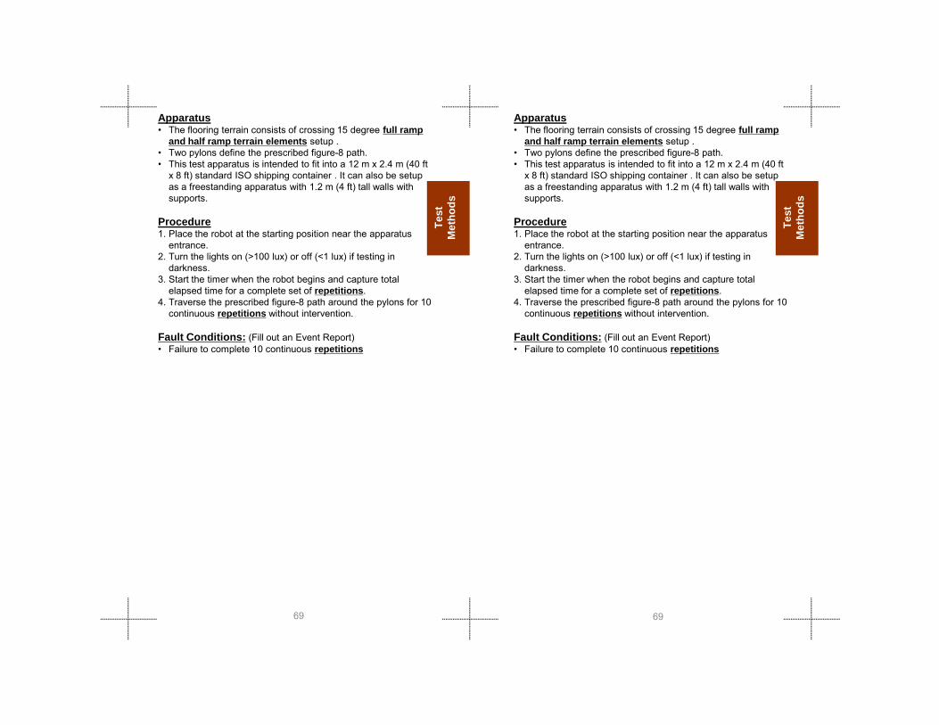
Test
M
etho
ds
Test
M
etho
ds
Apparatus• The flooring terrain consists of crossing 15 degree full ramp
and half ramp terrain elements setup .• Two pylons define the prescribed figure-8 path.• This test apparatus is intended to fit into a 12 m x 2.4 m (40 ft
x 8 ft) standard ISO shipping container . It can also be setup as a freestanding apparatus with 1.2 m (4 ft) tall walls with supports.
Procedure1. Place the robot at the starting position near the apparatus
entrance. 2. Turn the lights on (>100 lux) or off (<1 lux) if testing in
darkness.3. Start the timer when the robot begins and capture total
elapsed time for a complete set of repetitions.4. Traverse the prescribed figure-8 path around the pylons for 10
continuous repetitions without intervention.
Fault Conditions: (Fill out an Event Report)• Failure to complete 10 continuous repetitions
6969
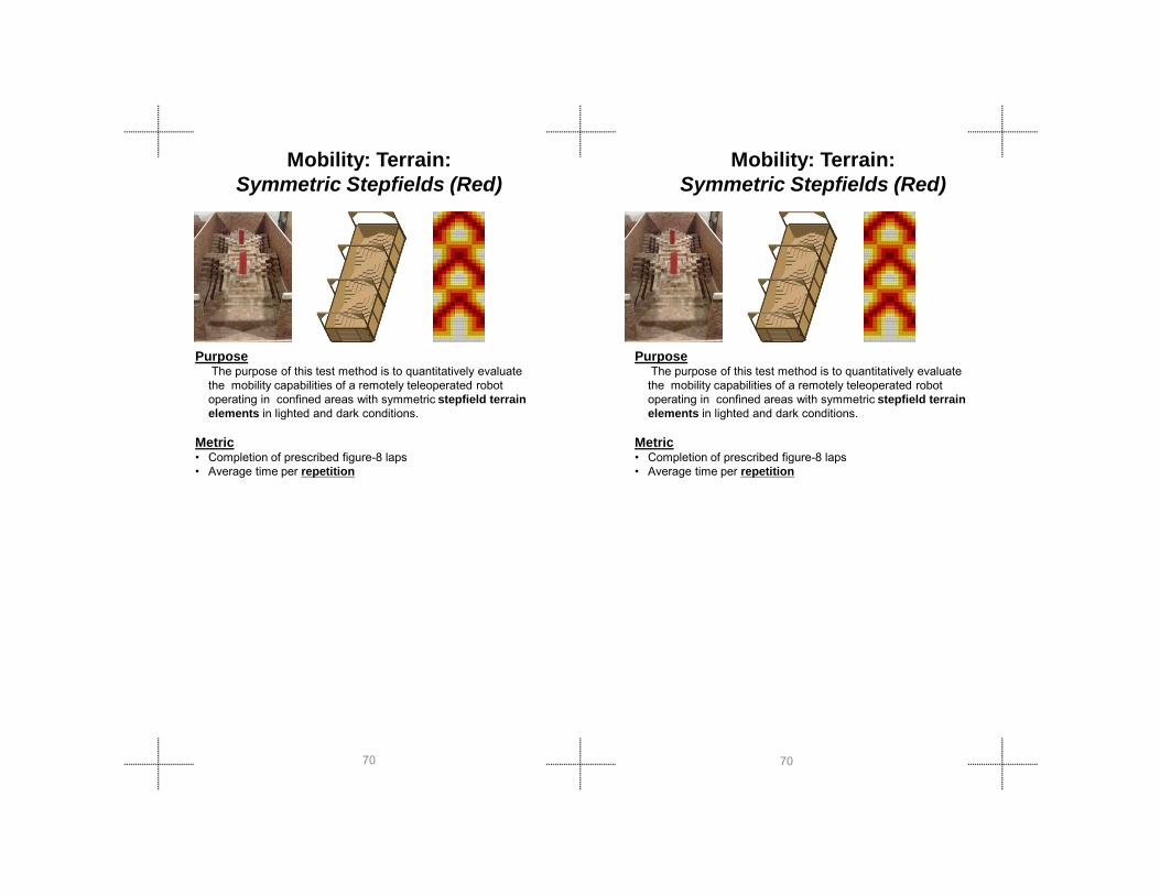
PurposeThe purpose of this test method is to quantitatively evaluate the mobility capabilities of a remotely teleoperated robot operating in confined areas with symmetric stepfield terrain elements in lighted and dark conditions.
Metric
Mobility: Terrain:Symmetric Stepfields (Red)
Mobility: Terrain:Symmetric Stepfields (Red)
PurposeThe purpose of this test method is to quantitatively evaluate the mobility capabilities of a remotely teleoperated robot operating in confined areas with symmetric stepfield terrain elements in lighted and dark conditions.
Metric
7070
• Completion of prescribed figure-8 laps• Average time per repetition
• Completion of prescribed figure-8 laps• Average time per repetition

Test
M
etho
ds
Test
M
etho
ds
Apparatus• The flooring terrain consists of symmetric stepfield terrain
element fabricated using 10 cm (4 in) square wood posts cut to prescribed lengths (10 cm, 20 cm, 30 cm, 40 cm, and 50 cm (4 in, 8 in, 12 in, 16 in, and 20 in)) and setup in groups of four posts per step height.
• Two pylons define the prescribed figure-8 path.• This test apparatus is intended to fit into a 12 m x 2.4 m
(40 ft x 8 ft) standard ISO shipping container. It can also be setup as a freestanding apparatus with 1.2 m (4 ft) tall walls with supports.
Procedure1. Place the robot at the starting position near the apparatus
entrance. 2. Turn the lights on (>100 lux) or off (<1 lux) if testing in
darkness.3. Start the timer when the robot begins and capture total
elapsed time for a complete set of repetitions.4. Traverse the prescribed figure-8 path around the pylons for
10 continuous repetitions without intervention.
Apparatus• The flooring terrain consists of symmetric stepfield
terrain element fabricated using 10 cm (4 in) square wood posts cut to prescribed lengths (10 cm, 20 cm, 30 cm, 40 cm, and 50 cm (4 in, 8 in, 12 in, 16 in, and 20 in)) and setup in groups of four posts per step height.
• Two pylons define the prescribed figure-8 path.• This test apparatus is intended to fit into a 12 m x 2.4 m
(40 ft x 8 ft) standard ISO shipping container. It can also be setup as a freestanding apparatus with 1.2 m (4 ft) tall walls with supports.
Procedure1. Place the robot at the starting position near the
apparatus entrance. 2. Turn the lights on (>100 lux) or off (<1 lux) if testing in
darkness.3. Start the timer when the robot begins and capture total
elapsed time for a complete set of repetitions.4. Traverse the prescribed figure-8 path around the pylons
for 10 continuous repetitions without intervention.
7171
p
Fault Conditions: (Fill out an Event Report)• Failure to complete 10 continuous repetitions
p
Fault Conditions: (Fill out an Event Report)• Failure to complete 10 continuous repetitions

Mobility: Obstacle:Inclined Plane(0- 90°)
PurposeThe purpose of this test method is to quantitatively evaluate the incline plane maneuvering capabilities, including variable chassis configurations, rollover potential, and de-tracking, of a remotely teleoperated robot operating in lighted and dark conditions.
START/END
VERTICALDIAGONAL
HORIZONTAL
Mobility: Obstacle:Inclined Plane(0°- 90°)
VERTICALDIAGONAL
PurposeThe purpose of this test method is to quantitatively evaluate the incline plane maneuvering capabilities, including variable chassis configurations, rollover potential, and de-tracking, of a remotely teleoperated robot operating in lighted and dark conditions.
7272
Metrics• Maximum incline (degrees) while completing 10 repetitions
each for vertical, diagonal, and horizontal paths.• Average time per repetition
Metrics• Maximum incline (degrees) while completing 10 repetitions
each for vertical, diagonal, and horizontal paths.• Average time per repetition
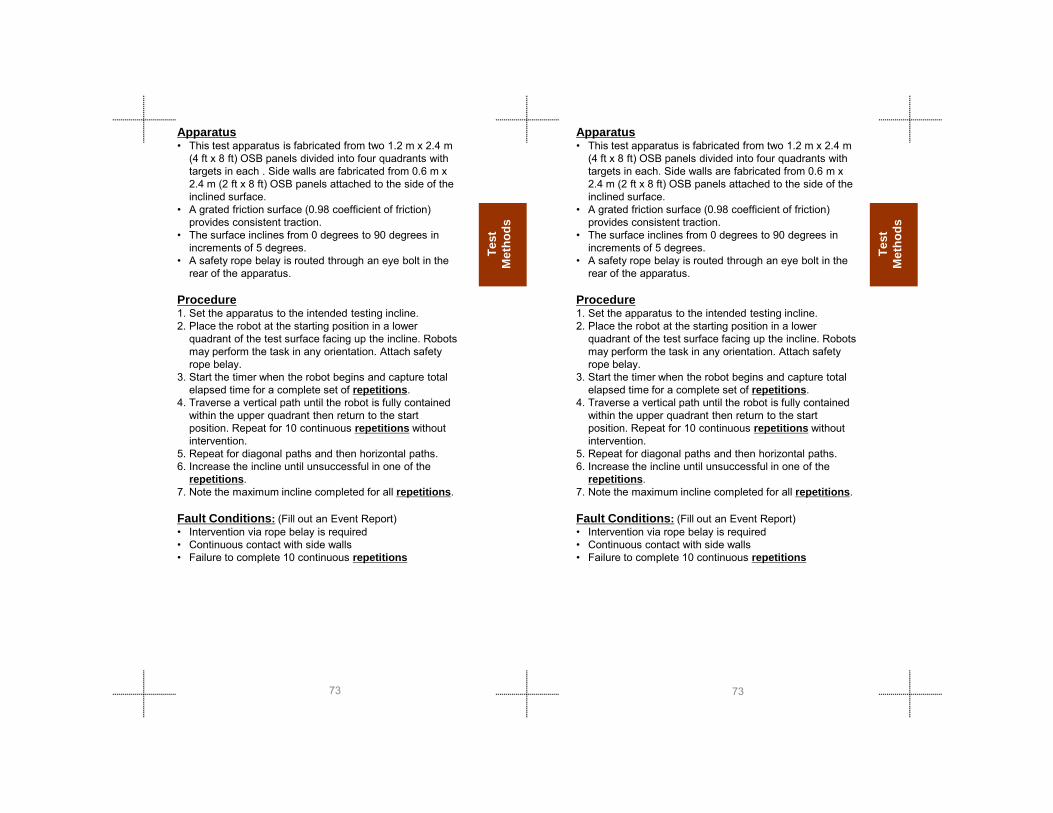
Test
M
etho
ds
Test
M
etho
ds
Apparatus• This test apparatus is fabricated from two 1.2 m x 2.4 m
(4 ft x 8 ft) OSB panels divided into four quadrants with targets in each . Side walls are fabricated from 0.6 m x 2.4 m (2 ft x 8 ft) OSB panels attached to the side of the inclined surface.
• A grated friction surface (0.98 coefficient of friction) provides consistent traction.
• The surface inclines from 0 degrees to 90 degrees in increments of 5 degrees.
• A safety rope belay is routed through an eye bolt in the rear of the apparatus.
Procedure1. Set the apparatus to the intended testing incline.2. Place the robot at the starting position in a lower
quadrant of the test surface facing up the incline. Robots may perform the task in any orientation. Attach safety rope belay.
3. Start the timer when the robot begins and capture total elapsed time for a complete set of repetitions.
4. Traverse a vertical path until the robot is fully contained
Apparatus• This test apparatus is fabricated from two 1.2 m x 2.4 m
(4 ft x 8 ft) OSB panels divided into four quadrants with targets in each. Side walls are fabricated from 0.6 m x 2.4 m (2 ft x 8 ft) OSB panels attached to the side of the inclined surface.
• A grated friction surface (0.98 coefficient of friction) provides consistent traction.
• The surface inclines from 0 degrees to 90 degrees in increments of 5 degrees.
• A safety rope belay is routed through an eye bolt in the rear of the apparatus.
Procedure1. Set the apparatus to the intended testing incline.2. Place the robot at the starting position in a lower
quadrant of the test surface facing up the incline. Robots may perform the task in any orientation. Attach safety rope belay.
3. Start the timer when the robot begins and capture total elapsed time for a complete set of repetitions.
4. Traverse a vertical path until the robot is fully contained
7373
p ywithin the upper quadrant then return to the start position. Repeat for 10 continuous repetitions without intervention.
5. Repeat for diagonal paths and then horizontal paths.6. Increase the incline until unsuccessful in one of the
repetitions.7. Note the maximum incline completed for all repetitions.
Fault Conditions: (Fill out an Event Report)• Intervention via rope belay is required• Continuous contact with side walls• Failure to complete 10 continuous repetitions
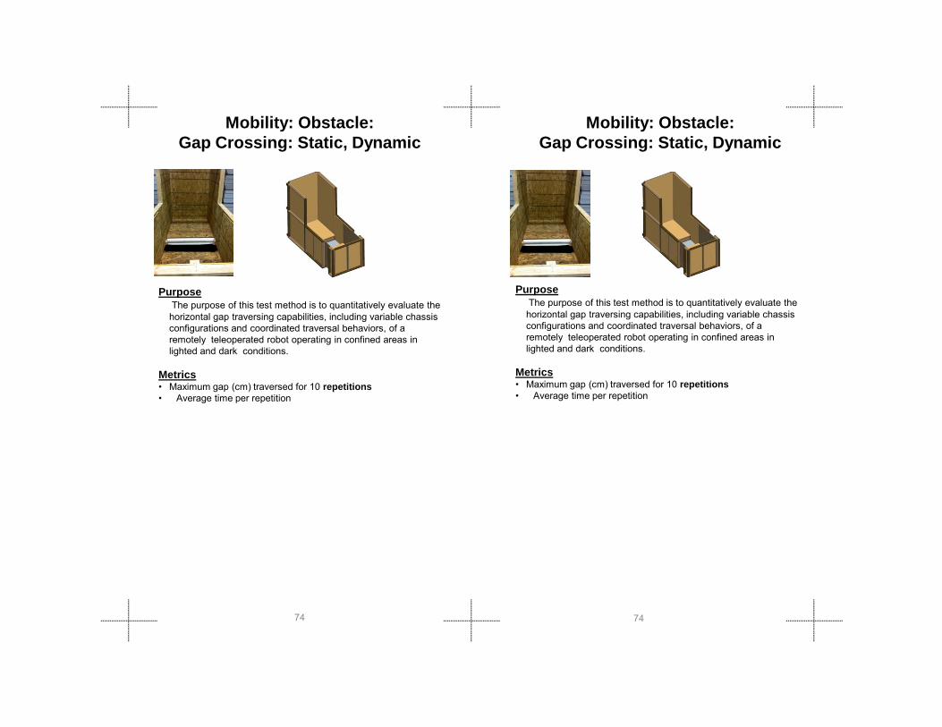
Mobility: Obstacle:Gap Crossing: Static, Dynamic
PurposeThe purpose of this test method is to quantitatively evaluate the horizontal gap traversing capabilities, including variable chassis configurations and coordinated traversal behaviors, of a remotely teleoperated robot operating in confined areas in lighted and dark conditions.
PurposeThe purpose of this test method is to quantitatively evaluate the horizontal gap traversing capabilities, including variable chassis configurations and coordinated traversal behaviors, of a remotely teleoperated robot operating in confined areas in lighted and dark conditions.
Mobility: Obstacle:Gap Crossing: Static, Dynamic
7474
Metrics• Maximum gap (cm) traversed for 10 repetitions • �Average time per repetition
Metrics• Maximum gap (cm) traversed for 10 repetitions • �Average time per repetition

Test
M
etho
ds
Test
M
etho
ds
Apparatus• This test apparatus is fabricated from two 1.2 m x 1.2 m (4
ft x 4 ft) OSB flat floor pallet elements placed side by side, separated by a controlled gap, with a surrounding containment wall.
• 10 cm (4 in) diameter pipes are level with the surface of the far edge of the gap and are free to roll to provide an uncertain reach edge on the initial traverse and launch edge on the return.
• The gap can be incremented from 10 cm to 100 cm (4 in to 40 in) in 10 cm (4 in) increments.
• A safety rope belay is routed through an eye bolt in the rear of the apparatus.
Procedure1. Set the apparatus to the intended testing gap.2. Place the robot at the starting position on one pallet facing
the obstacle. Robots may perform the task in any orientation. Attach safety rope belay.
3. Turn the lights on (>100 lux) or off (<1 lux) if testing in darkness.
4. Start the timer when the robot begins and capture total
Apparatus• This test apparatus is fabricated from two 1.2 m x 1.2 m
(4 ft x 4 ft) OSB flat floor pallet elements placed side by side, separated by a controlled gap, with a surrounding containment wall.
• 10 cm (4 in) diameter pipes are level with the surface of the far edge of the gap and are free to roll to provide an uncertain reach edge on the initial traverse and launch edge on the return.
• The gap can be incremented from 10 cm to 100 cm (4 in to 40 in) in 10 cm (4 in) increments.
• A safety rope belay is routed through an eye bolt in the rear of the apparatus.
Procedure1. Set the apparatus to the intended testing gap.2. Place the robot at the starting position on one pallet
facing the obstacle. Robots may perform the task in any orientation. Attach safety rope belay.
3. Turn the lights on (>100 lux) or off (<1 lux) if testing in darkness.
4. Start the timer when the robot begins and capture total
7575
g pelapsed time for a complete set of repetitions.
5. Traverse the gap fully without touching the bottom surface of the gap until the entire robot is on the opposite platform, then similarly return to the start position. Repeat for 10 continuous repetitions without intervention.
6. Increase the gap until unsuccessful in one of the repetitions.
7. Note the maximum gap completed for all repetitions.
Fault Conditions: (Fill out an Event Report)• Intervention via safety rope belay is required• Touching bottom surface of the gap at any time• Failure to complete 10 continuous repetitions

Mobility: Obstacle:Pipe Steps
PurposeThe purpose of this test method is to quantitatively evaluate the vertical step surmounting capabilities, including variable chassis configurations and coordinated climbing behaviors, of a remotely teleoperated robot operating in confined areas in lighted and dark conditions.
7676
Metrics• Maximum elevation (cm) surmounted • Average time per repetition• Maximum elevation (cm) surmounted for 10 repetitions• Average time per repetition
Metrics• Maximum elevation (cm) surmounted • Average time per repetition• Maximum elevation (cm) surmounted for 10 repetitions• Average time per repetition

Test
M
etho
ds
Test
M
etho
ds
Apparatus• This test apparatus is fabricated from two stacks of 1.2 m x
1.2 m (4 ft x 4 ft) OSB flat floor pallet elements placed side by side to form a step with a surrounding containment wall.
• The elevated stack can be increased from 10 cm to 100 cm (4 in to 40 in) in 10 cm (4 in) increments.
• Plastic pipes with a diameter of 10 cm (4 in) are stacked along with the each pallet to reduce edge traction.
• The plastic pipes are constrained against the elevated pallets but are free to rotate.
• A safety rope belay is routed through an eye bolt in the rear wall of the apparatus.
Procedure1. Set the apparatus to the intended testing elevation.2. Place the robot at the starting position on one pallet facing
the obstacle. Robots may perform the task in any orientation. Attach safety rope belay.
3. Turn the lights on (>100 lux) or off (<1 lux) if testing in darkness.
4 Start the timer when the robot begins and capture total
Apparatus• This test apparatus is fabricated from two stacks of 1.2 m
x 1.2 m (4 ft x 4 ft) OSB flat floor pallet elementsplaced side by side to form a step with a surrounding containment wall.
• The elevated stack can be increased from 10 cm to 100 cm (4 in to 40 in) in 10 cm (4 in) increments.
• Plastic pipes with a diameter of 10 cm (4 in) are stacked along with the each pallet to reduce edge traction.
• The plastic pipes are constrained against the elevated pallets but are free to rotate.
• A safety rope belay is routed through an eye bolt in the rear wall of the apparatus.
Procedure1. Set the apparatus to the intended testing elevation.2. Place the robot at the starting position on one pallet
facing the obstacle. Robots may perform the task in any orientation. Attach safety rope belay.
3. Turn the lights on (>100 lux) or off (<1 lux) if testing in darkness.
4 Start the timer when the robot begins and capture total
7777
4. Start the timer when the robot begins and capture total elapsed time for a complete set of repetitions.
5. Surmount the pipe step fully so that the entire robot is on the elevated platform with no overhang or contact with the pipes, then return to the start position. Repeat for 10 continuous repetitions without intervention.
6. Increase the pipe step elevation until unsuccessful in one of the repetitions.
Fault Conditions: (Fill out an Event Report)• Intervention via safety rope belay is required• Failure to complete 10 continuous repetitions

PurposeThe purpose of this test method is to quantitatively evaluate the stair ascending/descending capabilities, including variable chassis configurations, coordinated climbing behaviors, and tread surface vulnerabilities, for a remotely teleoperated robot operating in confined areas in lighted and dark conditions.
Mobility: Obstacle:Stairs (30°/35°/40°/45°;Wood/Metal)
Mobility: Obstacle:Stairs (30°/35°/40°/45°;Wood/Metal)
PurposeThe purpose of this test method is to quantitatively evaluate the stair ascending/descending capabilities, including variable chassis configurations, coordinated climbing behaviors, and tread surface vulnerabilities, for a remotely teleoperated robot operating in confined areas in lighted and dark conditions.
7878
Metrics• Maximum successful incline (degrees) with a variety of surface
conditions for 10 repetitions• Average time per repetition
Metrics• Maximum successful incline (degrees) with a variety of surface
conditions for 10 repetitions• Average time per repetition
Test
M
etho
ds
Test
M
etho
ds
Apparatus• Four different stair inclines (30°, 35°, 40°, 45°) are
available with two different stair tread surfaces, wood and “diamond plate” steel .
• Each apparatus contains five stairs with 20 cm (8 in) risers and 20 cm (8 in) treads with enclosed lower and upper landings made of 1.2 m x 1.2 m (4 ft x 4 ft) OSB.
• A removable containment wall encloses the lower landing at the start point.
• A safety rope belay is routed through an eye bolt in the rear wall of the apparatus.
Procedure1. Set the apparatus to the intended testing incline and
surface.2. Place the robot at the starting position facing the
obstacle. Robots may perform the task in any orientation. Attach safety rope belay. Enclose the robot with the lower landing containment wall
3. Turn the lights on (>100 lux) or off (<1 lux) if testing in darkness.
4. Start the timer when the robot begins and capture total
7979
g pelapsed time for a complete set of repetitions.
5. Surmount the stairs fully so that the entire robot is on the elevated landing with no overhang or contact with the stairs, then return to the start position. Repeat for 10 continuous repetitions without intervention..
6. Repeat with other stair tread surfaces. 7. Increase the stair incline until unsuccessful in one of the
repetitions. 8. Note the maximum incline completed with all surfaces for
all repetitions.
Fault Conditions: (Fill out an Event Report)• Intervention via safety rope belay is required• Failure to complete 10 continuous repetitions

Mobility: Obstacle:Confined Space
Mobility: Obstacle:Confined Space
PurposeThe purpose of this test method is to quantitatively evaluate the confined space maneuvering capabilities of a robot while being remotely teleoperated in complex terrain with lighted and dark conditions.
.
PurposeThe purpose of this test method is to quantitatively evaluate the confined space maneuvering capabilities of a robot while being remotely teleoperated in complex terrain with lighted and dark conditions.
.
8080
Metrics• Completion of 10 figure-8 repetitions• Average time per repetition
Metrics• Completion of 10 figure-8 repetitions• Average time per repetition
Test
M
etho
ds
Test
M
etho
ds
Apparatus• The flooring terrain consists of symmetric stepfield
terrain element fabricated using 10 cm (4 in) square wood posts cut to prescribed lengths (10 cm, 20 cm, 30 cm, 40 cm, and 50 cm(4 in, 8 in, 12 in, 16 in, and 20 in) and setup in groups of four posts per step height .
• Two pylons define the prescribed figure-8 path.• This test apparatus is intended to fit into a 12 m x 2.4 m
(40 ft x 8 ft) standard ISO shipping container . It can also be setup as a freestanding apparatus with 1.2 m (4 ft) tall walls with supports.
• A descending ceiling element with stalactites is used to narrow the vertical access dimension in 10 cm (4 in) increments. The pattern of stalactites is inverted from the flooring terrain so that ceiling features fill the valley features of the flooring terrain.
Procedure1. Place the robot at the starting position near the
apparatus entrance. 2. Turn the lights on (>100 lux) or off (<1 lux) if testing in
darkness.
Apparatus• The flooring terrain consists of symmetric stepfield
terrain element fabricated using 10 cm (4 in) square wood posts cut to prescribed lengths (10 cm, 20 cm, 30 cm, 40 cm, and 50 cm(4 in, 8 in, 12 in, 16 in, and 20 in) and setup in groups of four posts per step height .
• Two pylons define the prescribed figure-8 path.• This test apparatus is intended to fit into a 12 m x 2.4
m (40 ft x 8 ft) standard ISO shipping container . It can also be setup as a freestanding apparatus with 1.2 m(4 ft) tall walls with supports.
• A descending ceiling element with stalactites is used to narrow the vertical access dimension in 10 cm (4 in) increments. The pattern of stalactites is inverted from the flooring terrain so that ceiling features fill the valley features of the flooring terrain.
Procedure1. Place the robot at the starting position near the
apparatus entrance. 2. Turn the lights on (>100 lux) or off (<1 lux) if testing in
8181
3. Start the timer when the robot begins and capture total elapsed time for a complete set of repetitions.
4. Traverse the figure-8 path around the pylons continuously without intervention until all repetitions are complete
Fault Conditions: (Fill out an Event Report)• Failure to complete 10 continuous repetitions
g ( ) ( ) gdarkness.
3. Start the timer when the robot begins and capture total elapsed time for a complete set of repetitions.
4. Traverse the figure-8 path around the pylons continuously without intervention until all repetitions are complete
Fault Conditions: (Fill out an Event Report)• Failure to complete 10 continuous repetitions

PurposeThe purpose of this test method is to quantitatively evaluate the grasped towing capabilities for a remotely teleoperated robot operating on a flat/paved surface with confined area turns.
Metrics• Maximum weight dragged (kg) for 10 repetitions
Mobility: Towing:Grasped Sleds
FIGURE A
Mobility: Towing:Grasped Sleds
FIGURE A
PurposeThe purpose of this test method is to quantitatively evaluate the grasped towing capabilities for a remotely teleoperated robot operating on a flat/paved surface with confined area turns.
Metrics• Maximum weight dragged (kg) for 10 repetitions
8282
g gg ( g) p• Average time per repetition
g gg ( g) p• Average time per repetition

Test
M
etho
ds
Test
M
etho
ds
Apparatus• This test apparatus is a flat, straight, paved path of 50 m
(165 ft) between two pylons• Each pylon has a clearly marked turning boundary with a
radius of 2 m (6.5 ft) marked by a chalk or paint line (FIGURE B).
• A drag sled with a knotted handle is used for towing • A set of standard weights of 2 kg (5 lbs) and 11 kg (25 lbs)
are available to load the sled.• A set of backpacks weighing 5 kg (10 lbs) and 9 kg (20 lbs)
can also be used for drag weights less than the sled itself.
Procedure1. Place the drag sled at the starting position within a pylon
turning boundary. The operator may select the initial drag weight.
2. Place the robot at the starting position within a pylon turning boundary, near the drag sled but not attached in any way.
3. Start the timer when the robot begins and capture total elapsed time for a complete set of repetitions.
4. Remotely teleoperate the robot to grasp the sled in any
Apparatus• This test apparatus is a flat, straight, paved path of 50 m
(165 ft) between two pylons• Each pylon has a clearly marked turning boundary with a
radius of 2 m (6.5 ft) marked by a chalk or paint line (FIGURE B).
• A drag sled with a knotted handle is used for towing • A set of standard weights of 2 kg (5 lbs) and 11 kg
(25 lbs) are available to load the sled.• A set of backpacks weighing 5 kg (10 lbs) and 9 kg
(20 lbs) can also be used for drag weights less than the sled itself.
Procedure1. Place the drag sled at the starting position within a pylon
turning boundary. The operator may select the initial drag weight.
2. Place the robot at the starting position within a pylon turning boundary, near the drag sled but not attached in any way.
3. Start the timer when the robot begins and capture total elapsed time for a complete set of repetitions.
8383
y p g p yconvenient manner.
5. Traverse the prescribed figure-8 path around the pylons for 10 continuous repetitions without intervention. Maintain at least part of the robot and drag sled clearly inside the marked turning boundaries.
6. Failure to stay within the turning boundary negates the current lap. Teleoperate the robot to the starting position and continue with the timer running.
7. Increase the drag weight according to the operator’s chosen increment and repeat until unsuccessful in one of the repetitions or the operator is content with the last successful drag weight.
8. Note the maximum drag weight completed for all repetitions.
Fault Conditions: (Fill out an Event Report)• Failure to complete 10 continuous repetitions
p p p4. Remotely teleoperate the robot to grasp the sled in any
convenient manner.5. Traverse the prescribed figure-8 path around the pylons
for 10 continuous repetitions without intervention. Maintain at least part of the robot and drag sled clearly inside the marked turning boundaries.
6. Failure to stay within the turning boundary negates the current lap. Teleoperate the robot to the starting position and continue with the timer running.
7. Increase the drag weight according to the operator’s chosen increment and repeat until unsuccessful in one of the repetitions or the operator is content with the last successful drag weight.
8. Note the maximum drag weight completed for all repetitions.
Fault Conditions: (Fill out an Event Report)• Failure to complete 10 continuous repetitions
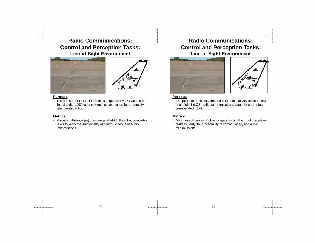
Radio Communications: Control and Perception Tasks:
Line-of-Sight Environment
PurposeThe purpose of this test method is to quantitatively evaluate the line of sight (LOS) radio communications range for a remotely teleoperated robot.
Metrics• Maximum distance (m) downrange at which the robot completes
100m
50m
100m
50m
PurposeThe purpose of this test method is to quantitatively evaluate the line of sight (LOS) radio communications range for a remotely teleoperated robot.
Metrics• Maximum distance (m) downrange at which the robot completes
Radio Communications: Control and Perception Tasks:
Line-of-Sight Environment
8484
( ) g ptasks to verify the functionality of control, video, and audio transmissions.
( ) g ptasks to verify the functionality of control, video, and audio transmissions.

Test
M
etho
ds
Test
M
etho
ds
Apparatus• The test apparatus for the LOS test is a straight flat
section of airstrip, roadway or similar surface at least 1 km (0.6 mi) long (longer if possible). The surface shall be consistent (e.g. asphalt or concrete) and be free of reflective objects at least 50 m (164 ft) on either side of the centerline.
• A figure-8 path with two 2 m (6.5 ft) radius lobes and 4 targets, facing four directions, shall be located at test distances of 50 m, 100 m, 200 m, 300 m (165 ft, 330 ft, 660 ft, 990 ft)... through the entire range of the test course.
• Operator station antennas shall be limited to a maximum of 2 m (6.5 ft) elevation above the ground.
Procedure1. Place the robot in the start position near the operator
station. 2. Traverse downrange to the next test station. 3. The control signal is tested by following the curved line.
The video signal is tested by identifying hazmat labels. The two-way audio is tested by an endless loop playing a predetermined set of keywords with the operator and
8585
predetermined set of keywords with the operator and administrator at each end identifying the words heard.
4. Upon arrival at a test station, center the robot wheels/tracks on the figure-8 path and follow the curve while maintaining line between tracks until directly in view of a recessed target placed at the center of the figure-8. Turn the robot towards the target and use any forward-facing sensor to identify the target. Panning of sensors is not allowed. Driving towards the target is allowed, but contact with the target is not. Return to the figure-8 path and continue around to next target until all four target are identified.
5. Repeat until a station is reached at which the control, video or audio transmissions fail. Report the last successful station range.
Fault Conditions: (Fill out an Event Report)• Deviating from prescribed figure-8 path while traversing
between targets within a station.• Touching the targets while attempting identification

PurposeThe p rpose of this test method is to q antitati el e al ate the
100m
50m
Radio Communications: Control and Perception Tasks:
Non-Line-of-Sight Range
PurposeThe p rpose of this test method is to q antitati el e al ate the
100m
50m
Radio Communications: Control and Perception Tasks:
Non-Line-of-Sight Range
8686
The purpose of this test method is to quantitatively evaluate the non-line-of-sight (NLOS) radio communications range for a remotely teleoperated robot.
Metrics• Maximum distance (m) behind a downrange metal monolith at
which the robot completes tasks to verify the functionality of control, video, and audio transmissions

Test
M
etho
ds
Test
M
etho
ds
Apparatus• The test apparatus for the NLOS test is identical to the
LOS except at a distance of 500 m (1640 ft) there is a wall constructed of standard ISO shipping containers (7.3 m high x 24.4 m wide (24 ft high x 80 ft wide)) with one edge aligned with the test course centerline and the long face perpendicular to the direction of robot travel.
• Three additional figure-8 paths are located behind and tangent to the metal wall to test robot operations in the radio shadow.
• Operator station antennas shall be limited to a maximum of 2 m (6.5 ft) elevation above the ground.
Procedure1. Determine standoff distance of operator station from
metal wall based on half the robot’s LOS performance data.
2. Place the robot in the start position near the operator station.
3. Traverse downrange to the next test station. 4. The control signal is tested by following the curved line.
The video signal is tested by identifying hazmat labels. The two-way audio is tested by an endless loop playing a
Apparatus• The test apparatus for the NLOS test is identical to the
LOS except at a distance of 500 m (1640 ft) there is a wall constructed of standard ISO shipping containers (7.3 mhigh x 24.4 m wide (24 ft high x 80 ft wide)) with one edge aligned with the test course centerline and the long face perpendicular to the direction of robot travel.
• Three additional figure-8 paths are located behind and tangent to the metal wall to test robot operations in the radio shadow.
• Operator station antennas shall be limited to a maximum of 2 m (6.5 ft) elevation above the ground.
Procedure1. Determine standoff distance of operator station from
metal wall based on half the robot’s LOS performance data.
2. Place the robot in the start position near the operator station.
3. Traverse downrange to the next test station. 4. The control signal is tested by following the curved line.
The video signal is tested by identifying hazmat labels. The two-way audio is tested by an endless loop playing a
8787
y y p p y gpredetermined set of keywords with the operator and administrator at each end identifying the words heard.
5. Upon arrival at a test station, center the robot wheels/tracks on the figure-8 path and follow the curve while maintaining line between tracks until directly in view of a recessed target placed at the center of the figure-8. Turn the robot towards the target and use any forward-facing sensor to identify the target. Panning of sensors is not allowed. Driving towards the target is allowed, but contact with the target is not. Return to the figure-8 path and continue around to next target until all four targetare identified.
6. Upon arrival at the ISO container monolith the robot should turn behind the container and proceed to a figure-8 test at 2 m (6.5 ft), 5 m (16.5 ft), and 12 m (40 ft) from the corner.
7. Repeat until a station is reached at which the control, video or audio transmissions fail. Report the last successful station range.
Fault Conditions: (Fill out an Event Report)• Deviating from prescribed figure-8 path while traversing
between targets within a station.• Touching the targets while attempting identification.
The two way audio is tested by an endless loop playing a predetermined set of keywords with the operator and administrator at each end identifying the words heard.
5. Upon arrival at a test station, center the robot wheels/tracks on the figure-8 path and follow the curve while maintaining line between tracks until directly in view of a recessed target placed at the center of the figure-8. Turn the robot towards the target and use any forward-facing sensor to identify the target. Panning of sensors is not allowed. Driving towards the target is allowed, but contact with the target is not. Return to the figure-8 path and continue around to next target until all four target are identified.
6. Upon arrival at the ISO container monolith the robot should turn behind the container and proceed to a figure-8 test at 2 m (6.5 ft), 5 m (16.5 ft), and 12 m (40 ft) from the corner.
7. Repeat until a station is reached at which the control, video or audio transmissions fail. Report the last successful station range.
Fault Conditions: (Fill out an Event Report)• Deviating from prescribed figure-8 path while traversing
between targets within a station.• Touching the targets while attempting identification.

Manipulation:Directed Perception: Open Access
PurposeThe purpose of this test method is to quantitatively evaluate the manipulator positioning capabilities of a remotely teleoperated robot operating on increasingly complex terrain in confined areas in lighted and dark conditions.
Manipulation:Directed Perception: Open Access
PurposeThe purpose of this test method is to quantitatively evaluate the manipulator positioning capabilities of a remotely teleoperated robot operating on increasingly complex terrain in confined areas in lighted and dark conditions.
8888
Metrics• Number of correctly identified targets within sub-divided cells
at various proximities and elevations relative to the robot• Average time per task
Metrics• Number of correctly identified targets within sub-divided cells
at various proximities and elevations relative to the robot• Average time per task

Test
M
etho
ds
Test
M
etho
ds
Apparatus• The apparatus for this test method contains two alcoves
which sub-divide the work volume to the front and side of the robot into roughly cubic cells in which targets are placed to be identified.
• Each alcove allows shelf placement at prescribed elevations (0 cm to 200 cm (0 in to 80 in) in 50 cm (20 in) increments).
• Each shelf is sub-divided into four cells. • The cells are accessible via circular holes of 15 cm
(6 in) diameter with hinged doors and magnetic closures.
• Ground level (0 cm (0 in)) cells have no front holes. • Full ramp terrain elements or symmetric stepfields
terrain elements, provide complexity in robot orientation and mobility.
• The start/end line is two terrain elements away from the front alcove.
Procedure1. Set the shelves to the intended testing elevation. Close
cell doors.
Apparatus• The apparatus for this test method contains two
alcoves which sub-divide the work volume to the front and side of the robot into roughly cubic cells in which targets are placed to be identified.
• Each alcove allows shelf placement at prescribed elevations (0 cm to 200 cm (0 in to 80 in) in 50 cm (20 in) increments).
• Each shelf is sub-divided into four cells. • The cells are accessible via circular holes of 15 cm
(6 in) diameter with hinged doors and magnetic closures.
• Ground level (0 cm (0 in)) cells have no front holes. • Full ramp terrain elements or symmetric stepfields
terrain elements, provide complexity in robot orientation and mobility.
• The start/end line is two terrain elements away from the front alcove.
Procedure1. Set the shelves to the intended testing elevation.
Close cell doors.
8989
2. Place the robot outside the start/end line facing the alcoves.
3. Turn the lights on (>100 lux) or off (<1 lux) if testing in darkness.
4. Start the timer when the robot crosses the start/end line to capture total elapsed time for a complete shelf elevation, ending when the robot exits past the start/end line.
5. Open each reachable cell access door with the manipulator tool tip and identify the target within. Bumping the apparatus to open doors is not allowed.
6. Repeat at the next higher shelf elevation until all elevations have been tested or the robot is no longer able to reach the cells.
7. Repeat all shelf elevations with other flooring options.8. Robots may exit past the start/end line for maintenance
or repairs.
Fault Conditions: (Fill out an Event Report)• Failure to return past the start/end line
2. Place the robot outside the start/end line facing the alcoves.
3. Turn the lights on (>100 lux) or off (<1 lux) if testing in darkness.
4. Start the timer when the robot crosses the start/end line to capture total elapsed time for a complete shelf elevation, ending when the robot exits past the start/end line.
5. Open each reachable cell access door with the manipulator tool tip and identify the target within. Bumping the apparatus to open doors is not allowed.
6. Repeat at the next higher shelf elevation until all elevations have been tested or the robot is no longer able to reach the cells.
7. Repeat all shelf elevations with other flooring options.8. Robots may exit past the start/end line for
maintenance or repairs.
Fault Conditions: (Fill out an Event Report)• Failure to return past the start/end line

PurposeThe purpose of this test method is to quantitatively evaluate the manipulator grasping and placement capability of a remotely teleoperated robot operating on increasingly complex terrain in confined areas in lighted and dark conditions.
Metrics
Manipulation:Grasping Dexterity: Open Access
Manipulation:Grasping Dexterity: Open Access
PurposeThe purpose of this test method is to quantitatively evaluate the manipulator grasping and placement capability of a remotely teleoperated robot operating on increasingly complex terrain in confined areas in lighted and dark conditions.
Metrics
9090
Metrics• Number of grasped pick and place objects within sub-
divided cells at various proximities and elevations relative to the robot
• Average time per task
Metrics• Number of grasped pick and place objects within sub-
divided cells at various proximities and elevations relative to the robot
• Average time per task

Test
M
etho
ds
Test
M
etho
ds
Apparatus• The apparatus for this test method contains two alcoves
which sub-divide the work volume to the front and side of the robot into roughly cubic cells in which pick and place tasks are performed.
• Each alcove allows shelf placement at prescribed elevations (0 cm, 50 cm, 100 cm, 150 cm, 200 cm (0 in, 20 in, 40 in, 60 in, 80 in)).
• Each shelf is sub-divided into four cells with 10 cm (4 in) pick and place objects placed on pegs in the near corner (shown as red in FIGURE A) and circular holes of 15 cm (6 in) diameter with hinged doors and magnetic closures (shown as blue in FIGURE A).
• Ground level (0 cm (0 in)) cells have no front holes.• Non-flat flooring conditions, either full ramp terrain
elements or symmetric stepfield terrain elements, provide complexity in robot orientation and mobility.
• The start/end line is two terrain elements away from the front alcove.
Procedure1. Set the shelves to the intended testing elevation. Close
cell doors Place the pick and place objects on their
9191
cell doors. Place the pick and place objects on their appropriate pegs.
2. Place the robot outside the start/end line facing the alcoves.
3. Turn the lights on (>100 lux) or off (<1 lux) if testing in darkness.
4. Start the timer when the robot crosses the start/end line to capture total elapsed time for a complete shelf elevation, ending when the robot exits past the start/end line.
5. Grasp each reachable pick and place object with the manipulator tool tip, remove from its recessed peg mount, and place through the corresponding cell access door.
6. Repeat at the next higher shelf elevation until all elevations have been tested or the robot is no longer able to reach the cells.
7. Repeat all shelf elevations with other flooring options.8. Robots may exit past the start/end line for maintenance
or repairs.
Fault Conditions: (Fill out an Event Report)• Failure to return past the start/end line

PurposeThe purpose of this test method is to quantitatively evaluate the the manipulator grasping and placement capabilities of a robot on increasingly complex terrain, including weighted payloads, while being remotely teleoperated in confined areas with lighted and dark conditions.
Manipulation:Grasping Dexterity: Weight Payloads
9292
Metrics• Number of grasped pick and place objects within sub-divided
cells at various proximities and elevations relative to the robot• Average time per task
Metrics• Number of grasped pick and place objects within sub-divided
cells at various proximities and elevations relative to the robot• Average time per task

Test
M
etho
ds
Test
M
etho
ds
Apparatus• The apparatus for this test method contains two alcoves
which sub-divide the work volume to the front and side of the robot into roughly cubic cells in which pick and place tasks are performed.
• Each alcove allows shelf placement at prescribed elevations (0 cm, 50 cm, 100 cm, 150 cm, 200 cm (0 in, 20 in, 40 in, 60 in, 80 in).
• Each shelf is sub-divided into four cells with 10 cm (4 in) diameter cylindrical pick and place objects with weights of 0.5kg (1lb), 3kg (7lbs), 7kg (15lbs) placed on pegs in the near corner and circular holes of 15 cm (6 in) diameter.
• Ground level (0 cm (0 in)) cells have no front holes.• Non-flat flooring conditions, either full ramp terrain elements
or symmetric stepfield terrain elements, provide complexity in robot orientation and mobility.
• The start/end line is two terrain elements away from the front alcove .
Procedure1. Set the shelves to the intended testing elevation. Close cell
doors. Place the pick and place objects on their appropriate
9393
pegs.2. Place the robot outside the start/end line facing the alcoves.3. Turn the lights on (>100 lux) or off (<1 lux) if testing in
darkness.4. Start the timer when the robot crosses the start/end line to
capture total elapsed time for a complete shelf elevation, ending when the robot exits past the start/end line.
5. Grasp each reachable pick and place object with the manipulator tool tip, remove from its recessed peg mount, and place through the corresponding cell access door.
6. Repeat at the next higher shelf elevation until all elevations have been tested or the robot is no longer able to reach the cells.
7. Repeat all shelf elevations with other flooring options.8. Robots may exit past the start/end line for maintenance or
repairs.
Fault Conditions: (Fill out an Event Report)• Failure to return past the start/end line

PurposeThe purpose of this test method is to quantitatively evaluate the door opening capability of a remotely teleoperated robot operating in confined areas in lighted and dark conditions.
M t i
Manipulation:Door Opening and Traversal Tasks
PurposeThe purpose of this test method is to quantitatively evaluate the door opening capability of a remotely teleoperated robot operating in confined areas in lighted and dark conditions.
M t i
Manipulation:Door Opening and Traversal Tasks
9494
Metrics• Completion of two subtasks: unlatching the door and
traversing through• Average time per repetition
Metrics• Completion of two subtasks: unlatching the door and
traversing through• Average time per repetition

Test
M
etho
ds
Test
M
etho
ds
Apparatus• The apparatus for this test method uses a set of common
household 90 cm (36 in) entry doors that are installed on frames.
• The doors are to have the following types of handles and locks for opening: lever and knob, push and pull, spring loaded and not, flat and with a step.
• The latches can be on left or right side of the door .• The starting line will be marked on the floor at 1.2 m (4 ft)
from the door.
Procedure1. Place the robot at the starting position facing the door. Ensure
that the door is latched, but not locked. 2. Turn the lights on (>100 lux) or off (<1 lux) if testing in
darkness.3. Start the timer when the robot begins and capture total
elapsed time for a complete set of repetitions.4. Open the door and drive through to the other side so the robot
is clear of the door (spring loaded doors should shut). Repeat for 10 continuous repetitions without intervention.
5 R t th d f th it id f 10
Apparatus• The apparatus for this test method uses a set of common
household 90 cm (36 in) entry doors that are installed on frames.
• The doors are to have the following types of handles and locks for opening: lever and knob, push and pull, spring loaded and not, flat and with a step.
• The latches can be on left or right side of the door .• The starting line will be marked on the floor at 1.2 m (4 ft)
from the door.
Procedure1. Place the robot at the starting position facing the door. Ensure
that the door is latched, but not locked. 2. Turn the lights on (>100 lux) or off (<1 lux) if testing in
darkness.3. Start the timer when the robot begins and capture total
elapsed time for a complete set of repetitions.4. Open the door and drive through to the other side so the robot
is clear of the door (spring loaded doors should shut). Repeat for 10 continuous repetitions without intervention.
5 Repeat the same door from the opposite side for 10
9595
5. Repeat the same door from the opposite side for 10 continuous repetitions without intervention.
6. Repeat for all other doors handle types and conditions.
Fault Conditions: (Fill out an Event Report)• Failure to complete 10 continuous repetitionsd
5. Repeat the same door from the opposite side for 10 continuous repetitions without intervention.
6. Repeat for all other doors handle types and conditions.
Fault Conditions: (Fill out an Event Report)• Failure to complete 10 continuous repetitionsd

Human System Interaction:Navigation Tasks: Random Maze Navigation with Complex Terrain
PurposeThe purpose of this test method is to quantitatively evaluate the maneuvering navigation capability of a remotely teleoperated robot operating on complex terrain in confined areas in lighted and dark conditions..
PurposeThe purpose of this test method is to quantitatively evaluate the maneuvering navigation capability of a remotely teleoperated robot operating on complex terrain in confined areas in lighted and dark conditions..
Human System Interaction:Navigation Tasks: Random Maze Navigation with Complex Terrain
9696
Metrics• Number of full and half ramp flooring elements traversed
while wall following (“right-hand” or “left-hand”) through the maze (complexity measure).
• Completion time.
Metrics• Number of full and half ramp flooring elements traversed
while wall following (“right-hand” or “left-hand”) through the maze (complexity measure).
• Completion time.

Test
M
etho
ds
Test
M
etho
ds
Apparatus• This test apparatus is a random maze of 1.2 m (4 ft) wide
hallways constructed with 1.2 m x 2.4 m (4 ft x 8 ft) tall OSB walls.
• The overall dimensions are roughly 10 m x 15 m (33 ft x 50 ft).
• The flooring is made of continuous full and half ramp flooring elements to provide complexity in robot orientation and operator awareness .
• Targets are placed on the far walls of dead-ends only.
Procedure1. Place the robot at the starting position facing into the
apparatus.2. Turn the lights on (>100 lux) or off (<1 lux) if testing in
darkness.3. Start the timer when the robot begins and capture total
elapsed time for a complete negotiation of the maze ending when the robot returns to the start position.
4. Traverse the maze using the prescribed “right hand” or “left hand” wall following technique to navigate completely through the maze. Contact with the walls is allowed.
Apparatus• This test apparatus is a random maze of 1.2 m (4 ft) wide
hallways constructed with 1.2 m x 2.4 m (4 ft x 8 ft) tall OSB walls.
• The overall dimensions are roughly 10 m x 15 m (33 ft x 50 ft).
• The flooring is made of continuous full and half ramp flooring elements to provide complexity in robot orientation and operator awareness .
• Targets are placed on the far walls of dead-ends only.
Procedure1. Place the robot at the starting position facing into the
apparatus.2. Turn the lights on (>100 lux) or off (<1 lux) if testing in
darkness.3. Start the timer when the robot begins and capture total
elapsed time for a complete negotiation of the maze ending when the robot returns to the start position.
4. Traverse the maze using the prescribed “right hand” or “left hand” wall following technique to navigate completely through the maze Contact with the walls is allowed Flooring
9797
through the maze. Contact with the walls is allowed. Flooring pallets in dead-ends must be fully occupied to be counted (touch the Target on the far wall).
5. The robot may return to the start point to allow for maintenance and/or repairs during the test. The timer will be paused during maintenance and an Event Report should be generated.
6. The robot must return to the start point at the end of the test.
Fault Conditions: (Fill out an Event Report)• Failure to return to start point.

Human System Interaction:Navigation Tasks: Outdoor Navigation for Large UGV
PurposeThe purpose of this test method is to quantitatively evaluate a remotely operated robot capability to efficiently and completely map an unknown space with moderate feature complexities.
MetricsM difi d C H C it i
END
Human System Interaction:Navigation Tasks: Outdoor Navigation for Large UGV
PurposeThe purpose of this test method is to quantitatively evaluate a remotely operated robot capability to efficiently and completely map an unknown space with moderate feature complexities.
Metrics
END
9898
• Modified Cooper-Harper Criteria• Number of Safety Stops• Time to complete
• Modified Cooper-Harper Criteria• Number of Safety Stops• Time to complete
Test
M
etho
ds
Test
M
etho
ds
ApparatusThis test apparatus is a basic Figure-8 test course that is approximately 470 m (1531 ft) defined by a series of traffic control devices (stop signs and warning arrows), traffic cones, and organic obstacles. Stop signs accompanied by a sign containing red “X” signifies the end of the course.
Procedure1. Robot is placed at the start position and make sure the
course is clear2. Once safety officer confirms status, start timer and begin
run. 3. Drive the test course adhering the rules of the road4. Avoid obstacles. 5. Follow traffic signs6. Keep traffic cones on left7. During test, contact with walls and unsafe driving
maneuvers will result in a safety stop. 8. Stop at end the end of course.
9999
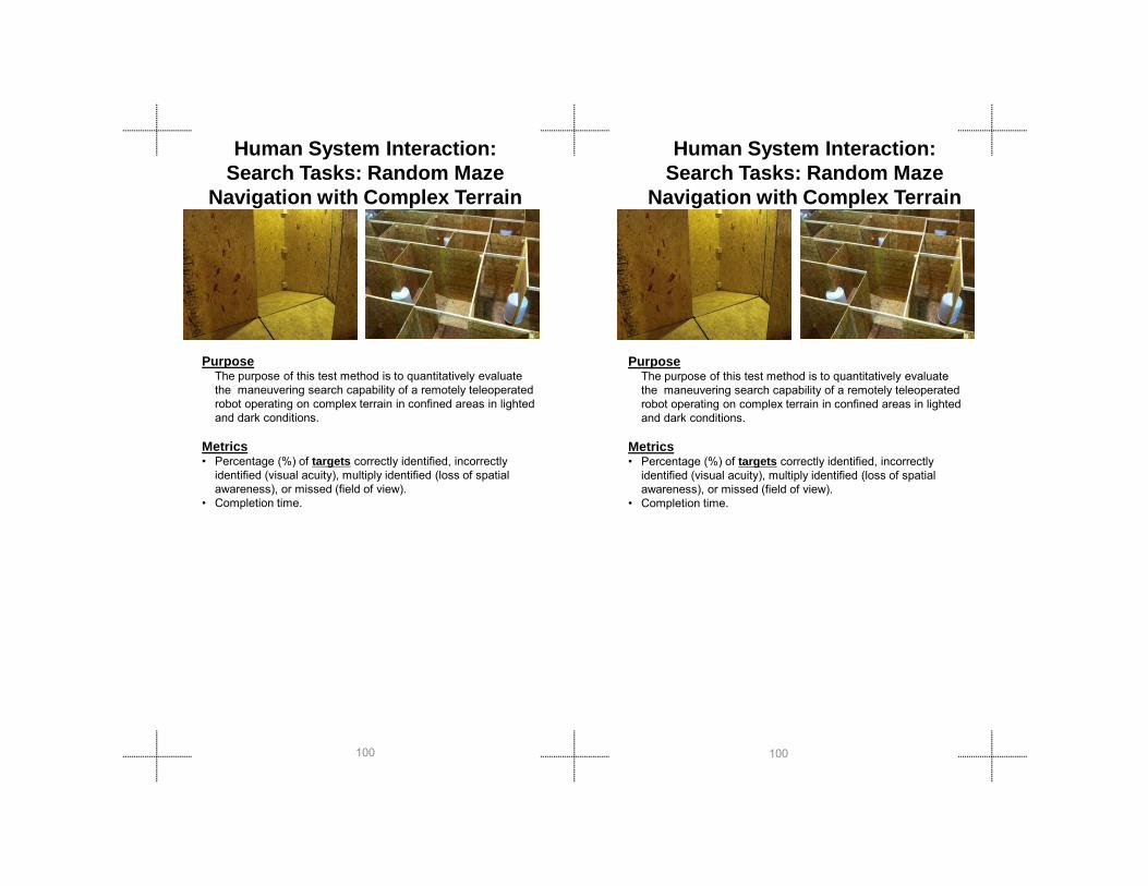
PurposeThe purpose of this test method is to quantitatively evaluate the maneuvering search capability of a remotely teleoperated robot operating on complex terrain in confined areas in lighted and dark conditions.
M t i
PurposeThe purpose of this test method is to quantitatively evaluate the maneuvering search capability of a remotely teleoperated robot operating on complex terrain in confined areas in lighted and dark conditions.
M t i
Human System Interaction:Search Tasks: Random Maze
Navigation with Complex Terrain
Human System Interaction:Search Tasks: Random Maze
Navigation with Complex Terrain
100100
Metrics• Percentage (%) of targets correctly identified, incorrectly
identified (visual acuity), multiply identified (loss of spatial awareness), or missed (field of view).
• Completion time.
Metrics• Percentage (%) of targets correctly identified, incorrectly
identified (visual acuity), multiply identified (loss of spatial awareness), or missed (field of view).
• Completion time.
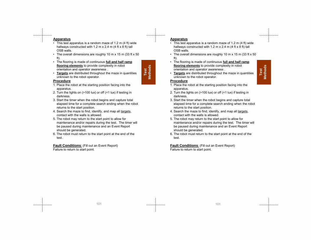
Test
M
etho
ds
Test
M
etho
ds
Apparatus• This test apparatus is a random maze of 1.2 m (4 ft) wide
hallways constructed with 1.2 m x 2.4 m (4 ft x 8 ft) tall OSB walls.
• The overall dimensions are roughly 10 m x 15 m (33 ft x 50 ft).
• The flooring is made of continuous full and half ramp flooring elements to provide complexity in robot orientation and operator awareness .
• Targets are distributed throughout the maze in quantities unknown to the robot operator.
Procedure1. Place the robot at the starting position facing into the
apparatus.2. Turn the lights on (>100 lux) or off (<1 lux) if testing in
darkness.3. Start the timer when the robot begins and capture total
elapsed time for a complete search ending when the robot returns to the start position.
4. Search the maze to find, identify, and map all targets, contact with the walls is allowed.
5. The robot may return to the start point to allow for
101101
y pmaintenance and/or repairs during the test. The timer will be paused during maintenance and an Event Report should be generated.
6. The robot must return to the start point at the end of the test.
Fault Conditions: (Fill out an Event Report)Failure to return to start point.
y pmaintenance and/or repairs during the test. The timer will be paused during maintenance and an Event Report should be generated.
6. The robot must return to the start point at the end of the test.
Fault Conditions: (Fill out an Event Report)Failure to return to start point.

PurposeThe purpose of this test method is to quantitatively evaluate the camera pointing capability of a remotely teleoperated robot operating underneath a low underpass, such as under a vehicle, with half ramp terrain elements and recessed targets in lighted and dark conditions.
PurposeThe purpose of this test method is to quantitatively evaluate the camera pointing capability of a remotely teleoperated robot operating underneath a low underpass, such as under a vehicle, with half ramp terrain elements and recessed targets in lighted and dark conditions.
Human System Interaction:Search Tasks: Under-Body Voids
with Complex Terrain
Human System Interaction:Search Tasks: Under-Body Voids
with Complex Terrain
102102
Metrics• Percentage of targets successfully identified at each level• Completion time.
Metrics• Percentage of targets successfully identified at each level• Completion time.

Test
M
etho
ds
Test
M
etho
ds
Apparatus• The flooring terrain consists of continuous half ramp
terrain elements setup to provide complexity for camera pointing.
• The ceiling consists of five 1.2 m x 2.4 m (4 ft x 8 ft) OSB panels with four 15 cm (6 in) holes cut in the various patterns, and 5 cm x 10 cm (2 in x 4 in) wood ribbing as occlusions.
• The ceiling panel elevations are adjustable in 10 cm (4 in) increments. This provides variable clearance underneath for different size robots.
• Each hole is covered by an inverted, opaque, 4 liter (1 gallon) can with a target inside to provide a recessed inspection task.
• Panels have unique hole locations therefore switching panels changes the hole patterns for the overall test .
• Not all holes are always fitted with cans and not every can has a target inside to identify.
• Empty holes are plugged to limit lighting under the ceiling.
• This test apparatus is intended to fit into a 12 m x 2.4 m (40 ft x 8 ft) standard ISO shipping container It can
103103
(40 ft x 8 ft) standard ISO shipping container. It can also be setup as a freestanding apparatus with 1.2 m (4 ft) tall walls with supports.
Procedure1. Set the ceiling apparatus to the intended clearance
elevation for testing. Note panel placement changes on form.
2. Place the robot at the starting position facing the apparatus.
3. Turn the lights on (>100 lux) or off (<1 lux) if testing in darkness.
4. Start the timer to capture total elapsed time for a complete search, ending when the robot returns to the start position.
5. Search the underpass at the elevation to identify all targets then return to the start point.
6. Change the target locations and/or the ceiling panels. Lower the ceiling one increment of 10 cm (4 in) and repeat.
Fault Conditions: (Fill out an Event Report)• Failure to return to start point.
(40 ft x 8 ft) standard ISO shipping container. It can also be setup as a freestanding apparatus with 1.2 m(4 ft) tall walls with supports.
Procedure1. Set the ceiling apparatus to the intended clearance
elevation for testing. Note panel placement changes on form.
2. Place the robot at the starting position facing the apparatus.
3. Turn the lights on (>100 lux) or off (<1 lux) if testing in darkness.
4. Start the timer to capture total elapsed time for a complete search, ending when the robot returns to the start position.
5. Search the underpass at the elevation to identify all targets then return to the start point.
6. Change the target locations and/or the ceiling panels. Lower the ceiling one increment of 10 cm (4 in) and repeat.
Fault Conditions: (Fill out an Event Report)• Failure to return to start point.

Sensor: Visual:Acuity and Field of View
PurposeThe purpose of this test method is to quantitatively evaluate the color video, visual acuity, field of view (FOV), zooming, and variable illumination capabilities of a remotely teleoperated robot operating in lighted and dark conditions.
Sensor: Visual:Acuity and Field of View
PurposeThe purpose of this test method is to quantitatively evaluate the color video, visual acuity, field of view (FOV), zooming, and variable illumination capabilities of a remotely teleoperated robot operating in lighted and dark conditions.
104104
Metrics
• Color video capability (check) • Near field acuity (Snellen fraction)• Far field acuity (Snellen fraction)• Field of view (degrees)
Metrics
• Color video capability (check) • Near field acuity (Snellen fraction)• Far field acuity (Snellen fraction)• Field of view (degrees)

Test
M
etho
ds
Test
M
etho
ds
Apparatus• This test apparatus is implemented in a 12 m x 2.4 m
(40 ft x 8 ft) standard ISO shipping container.• No flooring terrain is used. • Snellen far field eye charts and an assortment of
hazmat labels are posted on the wall at the far end of the container, 6 m (20 ft) from the centerline of the container, which is the standard distance for the eye chart usage.
• A Snellen near field eye chart is placed on a free standing pole which allows elevation adjustments for the eye chart to be aligned at 40 cm (16 in) away from the container center line and at the same level as the individual camera on the robot.
• The field of view lines are marked on the wall starting at the far end of the container with 5° separation from the point of view of the robot. Each side ranges from 5° to 60° to accommodate a 120° field of view
Procedure1. Note the camera features for each camera on the
105105
robot as per the form, and measure the lighting toensure at least 1000 lux.
2. Place the robot at the center of the containeranywhere behind the 6 m (20 ft) line. The robot isallowed to move within the container but no part of therobot may cross the line.
3. Measure the field of view of the camera by countingorange lines to the widest angle.
4. Read the eye charts from the 6 m (20 ft) distance andcircle the decimal equivalent for the smallest correctline read normally and then with the zoom lens ifavailable.
5. Place the near field chart in front of the robot, 40 cm(16 in) from the line and at the same level as thecamera being tested. Read the near field chart andcircle smallest correct line read normally and with thezoom lens if available.
6. Repeat with the lights out (<1 lux).7. Repeat for all cameras on the robot.
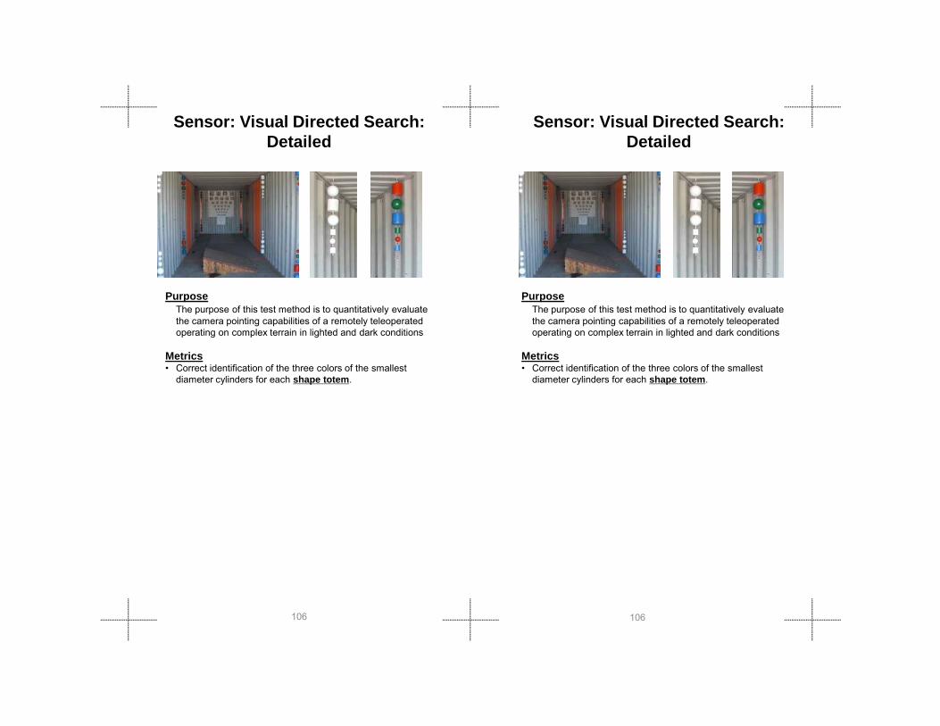
Sensor: Visual Directed Search:Detailed
PurposeThe purpose of this test method is to quantitatively evaluate the camera pointing capabilities of a remotely teleoperated operating on complex terrain in lighted and dark conditions
Metrics
PurposeThe purpose of this test method is to quantitatively evaluate the camera pointing capabilities of a remotely teleoperated operating on complex terrain in lighted and dark conditions
Metrics
Sensor: Visual Directed Search:Detailed
106106
• Correct identification of the three colors of the smallest diameter cylinders for each shape totem.
• Correct identification of the three colors of the smallest diameter cylinders for each shape totem.

Test
M
etho
ds
Test
M
etho
ds
Apparatus• This test apparatus is contained in a 2.4 m x 12 m (8 ft x
40 ft) standard ISO shipping container to allow testing in almost complete darkness (< 1 lux) and environmental complexity such as smoke, rain, etc.
• A full ramp terrain element with friction surface is placed at the center of the container to maintain the robot on a side roll orientation relative to the major container axes and provide complexity in camera pointing.
• Twenty shape totems are placed along the edge of the container, equally spaced at five cross-planes from end to end.
• Each totem contains four cylindrical sections of decreasing diameter 100 mm, 50 mm, 10 mm, 1 mm (4 in, 2 in, 0.4 in, 0.04 in) .
• Each cylinder section is taped in three colors (red, green, and blue) in random order with lengths equal to the cylinder diameter.
107107
Procedure1. Place the robot on the full ramp terrain element in the
center of the container. The robot may rotate but must stay on the ramp during the entirety of the test. If the robot falls off the ramp, the robot must return to the ramp before continuing identification of targets. Use any available cameras.
2. Identify all shape totems by identifying the colors for the smallest visible cylinders. Test administrator will verify over operator’s shoulder.
3. Points are given for each diameter cylinder: 1 point for the largest diameter to 4 points for the smallest diameter. Only the smallest correctly identified cylinders are scored for a given shape totem.
4. For each of the 5 targets (around the full ramp terrain element and on the ceiling above the ramp) each identifier is worth 4 point for a total of 20 points available.
5. Repeat with the lights out (<1 lux) if testing in darkness.

PurposeThe purpose of this test method is to quantitatively evaluate the camera pointing capabilities of a remotely teleoperated operating on complex terrain in lighted and dark conditions.
Metrics• Number of targets correctly identified.
PurposeThe purpose of this test method is to quantitatively evaluate the camera pointing capabilities of a remotely teleoperated operating on complex terrain in lighted and dark conditions.
Metrics• Number of targets correctly identified.
Sensor: Visual Directed Search:Rapid
Sensor: Visual Directed Search:Rapid
108108
g y• Average time per target.
g y• Average time per target.

Test
M
etho
ds
Test
M
etho
ds
Apparatus• This test apparatus is contained in a 2.4 m x 12 m (8 ft x
40 ft) standard ISO shipping container to allow testing in almost complete darkness (< 1 lux) and environmental complexity such as smoke, rain, etc.
• A full ramp terrain element with friction surface is placed at the center of the container to maintain the robot on a side roll orientation relative to the major container axes and provide complexity in camera pointing.
• Twenty totems are placed along the edge of the container, equally spaced at five cross-planes from end to end.
• Each totem contains four cylindrical sections of decreasing diameter (100 mm, 50 mm, 10 mm, 1 mm (4 in, 2 in, 0.4 in, 0.04 in)) .
• Each cylinder section is taped in three colors (red, green, and blue) in random order with lengths equal to the cylinder diameter.
Procedure
109109
1. Place the robot on the full ramp terrain element in the center of the container. The robot may rotate but must stay on the ramp during the entirety of the test. If the robot falls off the ramp, the robot must return to the ramp before continuing identification of targets. Use any available cameras.
2. Indicate a sequence of 10 targets alternating from floor to ceiling and front to back. The two required targets in the mid-plane are the ceiling target and one of the four available ramp targets. Pick one floor target and one ceiling target from each of the other four cross-planes.
3. Record the number of targets correctly identified and the elapsed time.
4. Repeat with the lights off (<1 lux).
Fault Conditions: (Fill out an Event Report)• Failure to identify all 10 targets indicated

PurposeThe purpose of this test method is to quantitatively evaluate the one/two-way audio capabilities of a remotely teleoperated robot.
Metrics• Percentage of words correctly identified from lists of standard
PurposeThe purpose of this test method is to quantitatively evaluate the one/two-way audio capabilities of a remotely teleoperated robot.
Metrics• Percentage of words correctly identified from lists of standard
Sensor: Speech Intelligibility Rhyming Words (2-way)
Sensor: Speech Intelligibility Rhyming Words (2-way)
110110
g yrhyming words spoken by male and female voices
g yrhyming words spoken by male and female voices
Test
M
etho
ds
Test
M
etho
ds
Apparatus• This test apparatus is a set of pre-recorded audio
pronunciations from male and female voices speaking standard rhyming words [ANSI S3.2 19/number sets.
• A computer or portable player is need to play randomly select words through a speaker system with a subwoofer.
• The speakers are initially placed 3 m (10 ft) in front of the remote robot the operator to identify at the operator station
• Then the system is reversed so the speakers play words at the operator station microphone for the operator to identify at the robot.
• Then the speakers are placed at the operator station.
Procedure1. Measure the background audio to ensure it is less than
50 dB.2. Place the robot at the start point facing the speakers. 3. To test the system from ROBOT TO OPERATOR, play
lt ti li t f 12 l d 12 f l d
111111
an alternating list of 12 male and 12 female words through the speakers in front of the robot. The words should be randomly generated and equally distributed between male and female. The robot operator should circle the word heard through the OCU on a list of all possible words provided. Headphones are allowed.
4. Reverse the system to test from OPERATOR TO ROBOT by switching the location of the speakers to the OCU and move the operator to the the position 3 m (10 ft) in front of the remote robot.
5. Play a different alternating male and female list of 24 words through the speakers into the OCU microphone. The words should be randomly generated and equally distributed between male and female. The operator should circle the word heard through the robot speaker(s) on a list of all possible words provided.

PurposeThe purpose of this test method is to quantitatively evaluate the one/two-way audio capabilities of a remotely teleoperated robot.
Metrics• Percentage of input
PurposeThe purpose of this test method is to quantitatively evaluate the one/two-way audio capabilities of a remotely teleoperated robot.
Metrics• Percentage of input
Sensor: Spectrum Response Tones Sensor: Spectrum Response Tones
112112
Percentage of input Percentage of input
Test
M
etho
ds
Test
M
etho
ds
Apparatus• This test apparatus includes a sound booth, a loudspeaker
measurement system, a personnel audio monitor, a calibrated microphone, and a turntable. During the test, the robot rests on the turntable within the sound booth. The microphone and audio monitor are alternately in the sound booth and station depending on the direction of the test.
Procedure1. Position the turntable at one end of the sound booth and
the audio monitor at the opposite end. The loudspeaker measurement system should be to not interfere with either the sound booth or robot control station.
2. Set up the collection sweep from 20Hz to 14000Hz with a minimum of one reading per octave.
3. Collect initial background levels. Position the microphone on the turntable facing the audio monitor. With the audio monitor disabled, collect an audio sweep.
4. Set output level. With the audio monitor enabled, collect a sequence of audio sweeps. Adjust the monitor output such that the measurements are 30db above background.
5. Collect sound booth background levels. Collect an audio sweep Rotate the turntable by 45° Collect an audio
Apparatus• This test apparatus includes a sound booth, a loudspeaker
measurement system, a personnel audio monitor, a calibrated microphone, and a turntable. During the test, the robot rests on the turntable within the sound booth. The microphone and audio monitor are alternately in the sound booth and station depending on the direction of the test.
Procedure1. Position the turntable at one end of the sound booth
and the audio monitor at the opposite end. The loud-2. speaker measurement system should be to not interfere
with either the sound booth or robot control station.3. Set up the collection sweep from 20Hz to 14000Hz with a
minimum of one reading per octave.4. Collect initial background levels. Position the microphone
on the turntable facing the audio monitor. With the audio monitor disabled, collect an audio sweep.
5. Set output level. With the audio monitor enabled, collect a sequence of audio sweeps. Adjust the monitor output such that the measurements are 30db above background.
6. Collect sound booth background levels. Collect an audio sweep Rotate the turntable by 45° Collect an audio
113113
sweep. Rotate the turntable by 45 . Collect an audio sweep at 45°, 90°, 135°, 180°, 225°, 270°, 315°, and again at 0°.
6. Position the robot on the turntable facing the audio monitor. Position the microphone near the robot controller’s speakers, where near relates to the common use of the robot control station.
7. Collect control station background levels. With the robot’s audio turned off, collect an audio sweep.
8. Collect robot background levels. With the audio monitor turned off, collect an audio sweep.
9. Collect robot radio audio levels. Collect an audio sweep with the turntable at 0°, 45°, 90°, 135°, 180°, 225°, 270°, 315°, and again at 0°.
10. Position the microphone in the sound booth and the audio monitor at the robot control station.
11. Collect sound booth background levels. With the robot’s audio turned off, collect an audio sweep.
12. Collect control station background levels. With the audio monitor turned off, collect an audio sweep.
13. Collect robot radio audio levels. Collect an audio sweep with the turntable at 0°, 45°, 90°, 135°, 180°, 225°, 270°, 315°, and again at 0°.
sweep. Rotate the turntable by 45 . Collect an audio sweep at 45°, 90°, 135°, 180°, 225°, 270°, 315°, and again at 0°.
7. Position the robot on the turntable facing the audio monitor. Position the microphone near the robot controller’s speakers, where near relates to the common use of the robot control station.
8. Collect control station background levels. With the robot’s audio turned off, collect an audio sweep.
9. Collect robot background levels. With the audio monitor turned off, collect an audio sweep.
10. Collect robot radio audio levels. Collect an audio sweep with the turntable at 0°, 45°, 90°, 135°, 180°, 225°, 270°, 315°, and again at 0°.
11. Position the microphone in the sound booth and the audio monitor at the robot control station.
12. Collect sound booth background levels. With the robot’s audio turned off, collect an audio sweep.
13. Collect control station background levels. With the audio monitor turned off, collect an audio sweep.
14. Collect robot radio audio levels. Collect an audio sweep with the turntable at 0°, 45°, 90°, 135°, 180°, 225°, 270°, 315°, and again at 0°.

PurposeThe purpose of this test method is to quantitatively evaluate a remotely operated robot capability to efficiently and completely map an unknown, indoor space with moderate terrain complexity ambient and dark conditions.
Metrics
Sensor: Localization and Mapping Tasks: Hallway Labyrinths with
Complex Terrain
Sensor: Localization and Mapping Tasks: Hallway Labyrinths with
Complex Terrain
PurposeThe purpose of this test method is to quantitatively evaluate a remotely operated robot capability to efficiently and completely map an unknown, indoor space with moderate terrain complexity ambient and dark conditions.
114114
Metrics• Coverage – ratio of fiducial elements to total number of
fiducial available• Fiducial Consistency – error between adjoining fiducial
elements• Structural Consistency – error in structural elements• Relative Accuracy - error between neighboring fiducials• Global Accuracy – error in locations of fiducials with
respect to a fixed coordinate frame• Relative Displacement – error in pose estimate
Test
M
etho
ds
Test
M
etho
ds
Apparatus• This test apparatus is a wall labyrinth constructed with 1.2 x
2.4 m (4 x 8 ft) OSB walls to form 1.2 m (4 ft) with an overall dimension of 12 x 2.4 m (40 x 8 ft). The flooring is made of continuous 15° pitch/roll full and half ramp flooring elements. Fiducial markers, approximately 1.2 m (4 ft) in diameter, will be distributed throughout the labyrinth in quantities unknown to the robot operator.
Procedure1. Robot is placed at the start position of the closed
course apparatus and start timer2. Traverse labyrinth to find, identify, and map all fiducial
markers. 3. During test, contact with walls are allowed. Maintenance
and repairs to robot are not permitted. 4. Produce geo-reference map, identifying all fiducial markers 5. Repeat 10 times
Apparatus• This test apparatus is a wall labyrinth constructed with 1.2
x 2.4 m (4 x 8 ft) OSB walls to form 1.2 m (4 ft) with an overall dimension of 12 x 2.4 m (40 x 8 ft). The flooring is made of continuous 15° pitch/roll full and half ramp flooring elements. Fiducial markers, approximately 1.2 m(4 ft) in diameter, will be distributed throughout the labyrinth in quantities unknown to the robot operator.
Procedure1. Robot is placed at the start position of the closed
course apparatus and start timer2. Traverse labyrinth to find, identify, and map all fiducial
markers. 3. During test, contact with walls are allowed. Maintenance
and repairs to robot are not permitted. 4. Produce geo-reference map, identifying all fiducial
markers 5. Repeat 10 times
115115

PurposeThe purpose of this test method is to quantitatively evaluate a remotely operated robot capability to efficiently and completely map an unknown space with moderate feature complexities.
Metrics• Coverage ratio of fiducial elements to total number of
Sensor: Localization and Mapping Tasks: Sparse Feature Maze
(Yellow)
PurposeThe purpose of this test method is to quantitatively evaluate a remotely operated robot capability to efficiently and completely map an unknown space with moderate feature complexities.
Metrics• Coverage ratio of fiducial elements to total number of
Sensor: Localization and Mapping Tasks: Sparse Feature Maze (Yellow)
116116
• Coverage – ratio of fiducial elements to total number of fiducial available
• Fiducial Consistency – error between adjoining fiducialelements
• Structural Consistency – error in structural elements• Relative Accuracy - error between neighboring fiducials• Global Accuracy – error in locations of fiducials with
respect to a fixed coordinate frame• Relative Displacement – error in pose estimate

Test
M
etho
ds
Test
M
etho
ds
Apparatus• This test apparatus is sparse feature maze is based
on the 9 x 9 square grid consisting of 2.4 m (8 ft) cells whose overall dimensions are roughly 19.5 x 19.5 m(64 x 64 ft). Fiducial markers will cover 30% of overall area.
Procedure1. Robot is placed at the start position of the apparatus
and start timer2. Traverse labyrinth to find, identify, and map all fiducial
markers. 3. During test, contact with walls are allowed.
Maintenance and repairs to robot are not permitted. 4. Produce geo-reference map, identifying all fiducial
markers
Apparatus• This test apparatus is sparse feature maze is based on
the 9 x 9 square grid consisting of 2.4 m (8 ft) cells whose overall dimensions are roughly 19.5 x 19.5 m(64 x 64 ft). Fiducial markers will cover 30% of overall area.
Procedure1. Robot is placed at the start position of the apparatus
and start timer2. Traverse labyrinth to find, identify, and map all fiducial
markers. 3. During test, contact with walls are allowed. Maintenance
and repairs to robot are not permitted. 4. Produce geo-reference map, identifying all fiducial
markers
117117

PurposeThe purpose of this test method is to quantitatively evaluate a remotely operated robot capability to efficiently and completely map an unknown space with moderate feature complexities.
Metrics• Coverage – ratio of fiducial elements to total number of
Sensor: Localization and Mapping Tasks: Sparse Feature Maze
(Orange)
118118
Coverage ratio of fiducial elements to total number of fiducial available
• Fiducial Consistency – error between adjoining fiducialelements
• Structural Consistency – error in structural elements• Relative Accuracy - error between neighboring fiducials• Global Accuracy – error in locations of fiducials with
respect to a fixed coordinate frame• Relative Displacement – error in pose estimate

Test
M
etho
ds
Test
M
etho
ds
Apparatus• This test apparatus is sparse feature maze is based on
the 9 x 9 square grid consisting of 2.4 m (8 ft) cells whose overall dimensions are roughly 19.5 x 19.5 m(64 x 64 ft). Fiducial markers will cover 16% of overall area.
Procedure1. Robot is placed at the start position of the apparatus
and start timer2. Traverse labyrinth to find, identify, and map all fiducial
markers. 3. During test, contact with walls are allowed. Maintenance
and repairs to robot are not permitted. 4. Produce geo-reference map, identifying all fiducial
markers
119119

PurposeThe purpose of this test method is to quantitatively evaluate a remotely operated robot capability to efficiently and completely map an unknown space with moderate feature complexities.
Metrics• Coverage – ratio of fiducial elements to total number of
Sensor: Localization and Mapping Tasks: Sparse Feature Maze (Red)
120120
Coverage ratio of fiducial elements to total number of fiducial available
• Fiducial Consistency – error between adjoining fiducialelements
• Structural Consistency – error in structural elements• Relative Accuracy - error between neighboring fiducials• Global Accuracy – error in locations of fiducials with
respect to a fixed coordinate frame• Relative Displacement – error in pose estimate

Test
M
etho
ds
Test
M
etho
ds
Apparatus• This test apparatus is sparse feature maze is based on
the 9 x 9 square grid consisting of 2.4 m (8 ft) cells whose overall dimensions are roughly 19.5 x 19.5 m(64 x 64 ft). Fiducial markers will cover 11% of overall area.
Procedure1. Robot is placed at the start position of the apparatus
and start timer2. Traverse labyrinth to find, identify, and map all fiducial
markers. 3. During test, contact with walls are allowed. Maintenance
and repairs to robot are not permitted. 4. Produce geo-reference map, identifying all fiducial
markers
121121
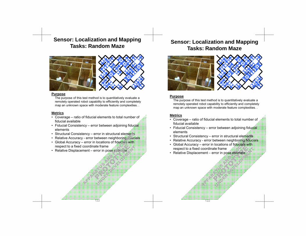
PurposeThe purpose of this test method is to quantitatively evaluate a remotely operated robot capability to efficiently and completely map an unknown space with moderate feature complexities. .
Metrics• Coverage – ratio of fiducial elements to total number of
Sensor: Localization and Mapping Tasks: Random Maze
PurposeThe purpose of this test method is to quantitatively evaluate a remotely operated robot capability to efficiently and completely map an unknown space with moderate feature complexities. .
MetricsC i f fid i l l l b f
Sensor: Localization and Mapping Tasks: Random Maze
122122
Coverage ratio of fiducial elements to total number of fiducial available
• Fiducial Consistency – error between adjoining fiducialelements
• Structural Consistency – error in structural elements• Relative Accuracy - error between neighboring fiducials• Global Accuracy – error in locations of fiducials with
respect to a fixed coordinate frame• Relative Displacement – error in pose estimate
• Coverage – ratio of fiducial elements to total number of fiducial available
• Fiducial Consistency – error between adjoining fiducialelements
• Structural Consistency – error in structural elements• Relative Accuracy - error between neighboring fiducials• Global Accuracy – error in locations of fiducials with
respect to a fixed coordinate frame• Relative Displacement – error in pose estimate
Test
M
etho
ds
Test
M
etho
ds
Apparatus• This test apparatus is a random maze constructed with
1.2 x 2.4 m (4 x 8 ft) OSB walls to form 1.2 m (4 ft) hallways and rooms of variable size (FIGURE B). The overall dimensions are roughly 10 x 15 m (33 x 50 ft) . The flooring is made of continuous 15° pitch/roll full and half ramp flooring elements and in a prescribed configuration (. Mapping elements are white cylindrical objects with a 1 m (1.2 ft) diameter that are distributed throughout the maze in quantities unknown to the robot operator.
Procedure1. Robot is placed at the start position of the apparatus and
start timer2. Traverse labyrinth to find, identify, and map all fiducial
markers. 3. During test, contact with walls are allowed. Maintenance
and repairs to robot are not permitted. 4. Produce geo-reference map, identifying all fiducial
markers
123123

Safety/Environment:Decontamination
PurposeThe purpose of this test method is to qualitatively evaluate a remotely operated robot’s washdown vulnerabilities and identify specific design issues that hinder complete decontamination.
Safety/Environment:Decontamination
PurposeThe purpose of this test method is to qualitatively evaluate a remotely operated robot’s washdown vulnerabilities and identify specific design issues that hinder complete decontamination.
124124
Metrics• Best practice, involves no metric
Metrics• Best practice, involves no metric

Test
M
etho
ds
Test
M
etho
ds
Apparatus• This test uses a simulated contaminant applied
consistently over the robot that is invisible in normal lighting, but glows in ultra-violet.
• The apparatus consists of an elevated platform in a washdown tub, a similar elevated platform in a rinsing tub, and an adjoining bridge.
• A low pressure water supply is used along with a set of typical brushes and additional tools used by the emergency responder community.
• A hand-held ultra-violet light source (black light) is also used.
Procedure1. Contaminate the robot with powder and/or liquid
simulants in a controlled area.2. Drive the robot onto the elevated platform in the
washdown tub.3. Operator decontaminate the robot using water and/or
brushes for 5 minutes.4. Administrator uses the black light to examine for the
125125
gexistence of contaminants out of sight of operator.
5. Repeat steps 3-4 until the robot is free of contaminants or 50 minutes of decontamination elapse.
gexistence of contaminants out of sight of operator.
5. Repeat steps 3-4 until the robot is free of contaminants or 50 minutes of decontamination elapse.
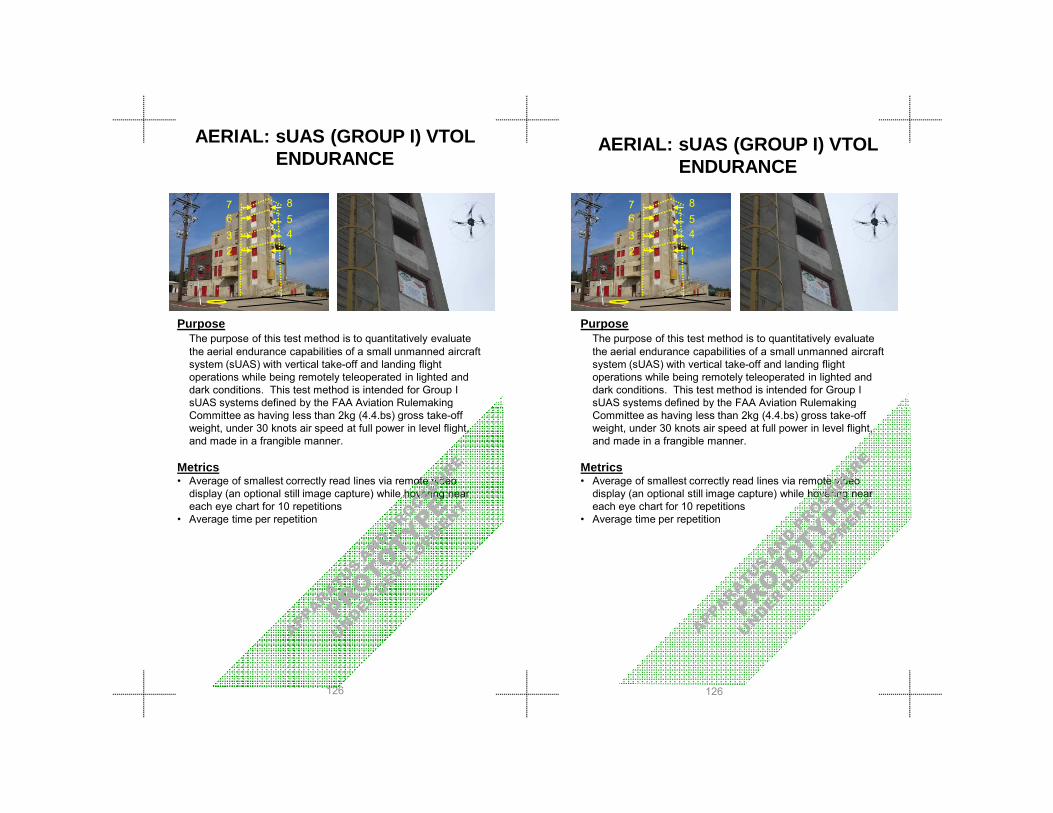
1458
2367
AERIAL: sUAS (GROUP I) VTOL ENDURANCE
1458
2367
PurposeThe purpose of this test method is to quantitatively evaluate the aerial endurance capabilities of a small unmanned aircraft system (sUAS) with vertical take-off and landing flight operations while being remotely teleoperated in lighted and dark conditions. This test method is intended for Group I sUAS systems defined by the FAA Aviation Rulemaking
PurposeThe purpose of this test method is to quantitatively evaluate the aerial endurance capabilities of a small unmanned aircraft system (sUAS) with vertical take-off and landing flight operations while being remotely teleoperated in lighted and dark conditions. This test method is intended for Group I sUAS systems defined by the FAA Aviation Rulemaking
AERIAL: sUAS (GROUP I) VTOL ENDURANCE
126126
y y gCommittee as having less than 2kg (4.4.bs) gross take-off weight, under 30 knots air speed at full power in level flight, and made in a frangible manner.
Metrics• Average of smallest correctly read lines via remote video
display (an optional still image capture) while hovering near each eye chart for 10 repetitions
• Average time per repetition
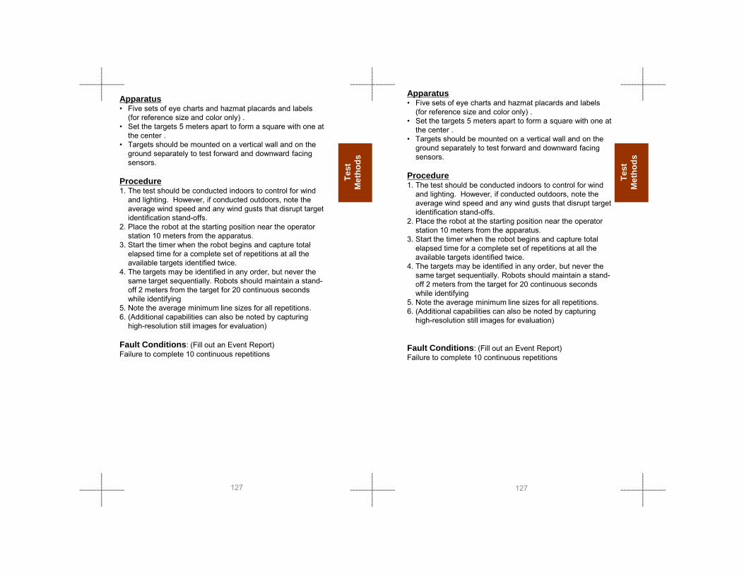
Test
M
etho
ds
Test
M
etho
ds
Apparatus• Five sets of eye charts and hazmat placards and labels
(for reference size and color only) .• Set the targets 5 meters apart to form a square with one at
the center .• Targets should be mounted on a vertical wall and on the
ground separately to test forward and downward facing sensors.
Procedure1. The test should be conducted indoors to control for wind
and lighting. However, if conducted outdoors, note the average wind speed and any wind gusts that disrupt target identification stand-offs.
2. Place the robot at the starting position near the operator station 10 meters from the apparatus.
3. Start the timer when the robot begins and capture total elapsed time for a complete set of repetitions at all the available targets identified twice.
4. The targets may be identified in any order, but never the same target sequentially. Robots should maintain a stand-ff 2 t f th t t f 20 ti d
Apparatus• Five sets of eye charts and hazmat placards and labels
(for reference size and color only) .• Set the targets 5 meters apart to form a square with one at
the center .• Targets should be mounted on a vertical wall and on the
ground separately to test forward and downward facing sensors.
Procedure1. The test should be conducted indoors to control for wind
and lighting. However, if conducted outdoors, note the average wind speed and any wind gusts that disrupt target identification stand-offs.
2. Place the robot at the starting position near the operator station 10 meters from the apparatus.
3. Start the timer when the robot begins and capture total elapsed time for a complete set of repetitions at all the available targets identified twice.
4. The targets may be identified in any order, but never the same target sequentially. Robots should maintain a stand-off 2 meters from the target for 20 continuous seconds
127127
off 2 meters from the target for 20 continuous seconds while identifying
5. Note the average minimum line sizes for all repetitions.6. (Additional capabilities can also be noted by capturing
high-resolution still images for evaluation)
Fault Conditions: (Fill out an Event Report) Failure to complete 10 continuous repetitions
gwhile identifying
5. Note the average minimum line sizes for all repetitions.6. (Additional capabilities can also be noted by capturing
high-resolution still images for evaluation)
Fault Conditions: (Fill out an Event Report) Failure to complete 10 continuous repetitions

AERIAL: AERIAL: sUAS (GROUP I) VTOL STATION-KEEPING
PurposeThe purpose of this test method is to quantitatively evaluate the aerial station-keeping capabilities of a small unmanned aircraft system (sUAS) with vertical take-off and landing flight operations, including visual acuity and obstacle avoidance/interaction, while being remotely teleoperated in lighted and dark conditions. This test method is intended for
128128
gGroup I sUAS systems defined by the FAA Aviation Rulemaking Committee as having less than 2kg (4.4.bs) gross take-off weight, under 30 knots air speed at full power in level flight, and made in a frangible manner.
Metrics• Average of smallest correctly read lines via remote video
display (an optional still image capture) while hovering near each eye chart for 10 repetitions
• Average time per repetition

Test
M
etho
ds
Test
M
etho
ds
Apparatus• Five sets of eye charts and hazmat placards and labels
(for reference size and color only) .• Set the targets 5 meters apart to form a square with one
at the center .• Targets should be mounted on a vertical wall and on the
ground separately to test forward and downward facing sensors.
Procedure1. The test should be conducted indoors to control for wind
and lighting. However, if conducted outdoors, note average wind speed and any wind gusts that disrupt target identification.
2. Place the robot at the starting position near the operator station 10 meters from the apparatus.
3. Start the timer when the robot begins and capture total elapsed time for a complete set of repetitions at all the available targets identified twice.
4. The targets may be identified in any order, but never the same target sequentially. Robots should maintain a stand off 2 meters from the target for 20 continuous
Apparatus• Five sets of eye charts and hazmat placards and labels
(for reference size and color only) .• Set the targets 5 meters apart to form a square with one
at the center .• Targets should be mounted on a vertical wall and on the
ground separately to test forward and downward facing sensors.
Procedure1. The test should be conducted indoors to control for wind
and lighting. However, if conducted outdoors, note average wind speed and any wind gusts that disrupt target identification.
2. Place the robot at the starting position near the operator station 10 meters from the apparatus.
3. Start the timer when the robot begins and capture total elapsed time for a complete set of repetitions at all the available targets identified twice.
4. The targets may be identified in any order, but never the same target sequentially. Robots should maintain a t d ff 2 t f th t t f 20 ti
129129
stand-off 2 meters from the target for 20 continuous seconds while identifying
5. Note the average minimum line sizes for all repetitions.6. (Additional capabilities can also be noted by capturing
high-resolution still images for evaluation)
Fault Conditions: (Fill out an Event Report) Failure to complete 10 continuous repetitions

Operational Task: Radio Comms: Nike Site
PurposeThe purpose of this operational task is to quantitatively evaluate the radio communications range, both line of sight (LOS) and non line of sight (NLOS), for a remotely teleoperated robot.
Operational Task: Radio Comms: Nike Site
PurposeThe purpose of this operational task is to quantitatively evaluate the radio communications range, both line of sight (LOS) and non line of sight (NLOS), for a remotely teleoperated robot.
130130
Metrics
• Percent of available stations completed for each task.
Metrics
• Percent of available stations completed for each task.

Test
M
etho
ds
Test
M
etho
ds
Apparatus• The test apparatus for the NIKE Site Radio Comms test
is a series of stations placed approximately 100 m (300 ft) from each other along a specified course around the NIKE Site. Each station contains figure-8 paths surrounding targets.
• Operator station antennas shall be limited to a maximum of 2 m (6.5 ft) elevation above the ground.
Procedure1. Place the robot in the start position near the operator
station.2. Traverse downrange to the next test station. 3. Center robot tracks on the figure-8 path and follow the
curve, while maintaining line between tracks, until directly in view of a recessed target placed at the center of the figure-8. Turn the robot towards the target and use any forward-facing sensor to identify the target. Panning of sensors is not allowed. Driving towards the target is allowed, but contact with the target is not. Return to the figure-8 path and continue around to next target.
4. Repeat steps 2 & 3 until a station is reached at which th id t l f il
Apparatus• The test apparatus for the NIKE Site Radio Comms
test is a series of stations placed approximately 100 m(300 ft) from each other along a specified course around the NIKE Site. Each station contains figure-8 paths surrounding targets.
• Operator station antennas shall be limited to a maximum of 2 m (6.5 ft) elevation above the ground.
Procedure1. Place the robot in the start position near the operator
station.2. Traverse downrange to the next test station. 3. Center robot tracks on the figure-8 path and follow the
curve, while maintaining line between tracks, until directly in view of a recessed target placed at the center of the figure-8. Turn the robot towards the target and use any forward-facing sensor to identify the target. Panning of sensors is not allowed. Driving towards the target is allowed, but contact with the target is not. Return to the figure-8 path and continue around to next target.
4. Repeat steps 2 & 3 until a station is reached at which th id t l f il
131131
the video or control fails.5. The radio systems shall be evaluated indirectly by
monitoring video and control system relative to a reference LOS distance of 50 m (164 ft).
6. Two-way audio will be tested by an endless loop playing a predetermined set of keywords. Operator will note the line number and which words were audible.
Fault Conditions: (Fill out an Event Report)• While traversing between targets within a station,
deviating from prescribed figure-8 path. If robot leaves the line due to latency or other reason, the test is ended at that station.
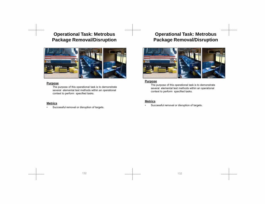
Operational Task: MetrobusPackage Removal/Disruption
PurposeThe purpose of this operational task is to demonstrate several elemental test methods within an operational context to perform specified tasks.
M i
Operational Task: MetrobusPackage Removal/Disruption
PurposeThe purpose of this operational task is to demonstrate several elemental test methods within an operational context to perform specified tasks.
Metrics
132132
Metrics• Successful removal or disruption of targets.
Metrics• Successful removal or disruption of targets.

Test
M
etho
ds
Test
M
etho
ds
Apparatus• Metrobus with seating and overhead shelves.• The Metrobus is populated with cases/backpacks
weighing 4.5 kg (10 lbs) and 9 kg (20 lbs), and small/large boxes.
• All packages lay flat with handles, if any, facing the seat front, or facing the aisle if located on the shelf and flush with the shelf edge.
Procedure1. Operator is located in operator station.2. Robot starts 100 m (328 ft) from bus and can be
outfitted with trailers or other such payloads to accomplish the task.
3. Task 1 is to remove targets with handles from all possible locations on the bus, transporting them to a location 100 m (328 ft) from the bus.
4. Task 2 is to disrupt in place (align disrupter with target, (simulated)) any targets that cannot be removed from the bus.
5. Locations include: front (wide aisle which allows diagonal approach), mid-bus (narrow aisle which
Apparatus• Metrobus with seating and overhead shelves.• The Metrobus is populated with cases/backpacks
weighing 4.5 kg (10 lbs) and 9 kg (20 lbs), and small/large boxes.
• All packages lay flat with handles, if any, facing the seat front, or facing the aisle if located on the shelf and flush with the shelf edge.
Procedure1. Operator is located in operator station.2. Robot starts 100 m (328 ft) from bus and can be outfitted
with trailers or other such payloads to accomplish the task.
3. Task 1 is to remove targets with handles from all possible locations on the bus, transporting them to a location 100 m (328 ft) from the bus.
4. Task 2 is to disrupt in place (align disrupter with target, (simulated)) any targets that cannot be removed from the bus.
5. Locations include: front (wide aisle which allows diagonal approach), mid-bus (narrow aisle which requires working
133133
g pp ), (requires working to the side of the robot), and back (wide aisle which allows diagonal approach but with occluded features and farther reach).
6. Elevations include: under seat which is 0 cm to 20 cm (0 in to 8 in), on seat, which is 50 cm to 70 cm (20 in to 28 in), and overhead shelf which is 160 cm to 178 cm (63 in to 70 in).
pp ), ( q gto the side of the robot), and back (wide aisle which allows diagonal approach but with occluded features and farther reach).
6. Elevations include: under seat which is 0 cm to 20 cm (0 in to 8 in), on seat, which is 50 cm to 70 cm (20 in to 28 in), and overhead shelf which is 160 cm to 178 cm (63 in to 70 in).

1458
2367
1458
2367
PurposeThe purpose of this operational task is to evaluate the aerial search capabilities of a small unmanned aircraft system (sUAS) with vertical take-off and landing flight operations, including station-keeping, visual acuity, and obstacle avoidance/interaction, while being remotely teleoperated around a multi-story building in lighted and dark conditions.
Operational Task:sUAS (GROUP I) VOTL EXTERIOR BUILDING
RECON:
PurposeThe purpose of this operational task is to evaluate the aerial search capabilities of a small unmanned aircraft system (sUAS) with vertical take-off and landing flight operations, including station-keeping, visual acuity, and obstacle avoidance/interaction, while being remotely teleoperated around a multi-story building in lighted and dark conditions.
Operational Task:sUAS (GROUP I) VOTL EXTERIOR BUILDING RECON:
134134
y g gThis test method is intended for Group I sUAS systems defined by the FAA Aviation Rulemaking Committee as having less than 2kg (4.4.bs) gross take-off weight, under 30 knots air speed at full power in level flight, and made in a frangible manner..
Metrics• Successful identification of targets in specified windows.

Test
M
etho
ds
Test
M
etho
ds
Apparatus• Multi-story building with three or more floors and some
openable windows, preferably on two sides of a building corner to include wind effects. Roof access can provide additional upward-facing target locations.
• Targets within each window should consist of visual acuity charts and hazmat placards (large) and labels (small).
• Four different target viewing conditions should be setup:• Open window, flush mounted • Open window, recessed 2-meters inside • Closed window, flush mounted • Closed window, recessed 2-meters inside
Procedure1. Operator is located in operator station 50 meters from
building. 2. Robot starts at the designated start position near the operator
station.3. Locate and search each window in the path shown to
correctly identify the smallest visual targets possible in as many windows as possible before returning to the the start position to land
Apparatus• Multi-story building with three or more floors and some
openable windows, preferably on two sides of a building corner to include wind effects. Roof access can provide additional upward-facing target locations.
• Targets within each window should consist of visual acuity charts and hazmat placards (large) and labels (small).
• Four different target viewing conditions should be setup:• Open window, flush mounted • Open window, recessed 2-meters inside • Closed window, flush mounted • Closed window, recessed 2-meters inside
Procedure1. Operator is located in operator station 50 meters from
building. 2. Robot starts at the designated start position near the operator
station.3. Locate and search each window in the path shown to
correctly identify the smallest visual targets possible in as many windows as possible before returning to the the start position to land.
135135
position to land. p

Underwater Navigation and SearchManeuvering Aquatic
PurposeThe purpose of this test method is to quantitatively evaluate robot’s ability to provide video of a underwater environment to facilitate operator’s ability to gain spatial awareness and to conduct teleoperated search. This test method allows direct comparisons across different robot models and particular
fi ti f i il b t d l
136136
configurations of similar robot models.
MetricsWhether reaching the end point or not; time used; number of targets correctly and incorrectly identified, missed, or multiply identified
configurations of similar robot models.
MetricsWhether reaching the end point or not; time used; number of targets correctly and incorrectly identified, missed, or multiply identified

Test
M
etho
ds
Test
M
etho
ds
ApparatusThis test apparatus is implemented in lake or river . A set of standardized objects is used and individual objects can be randomly ordered.
Procedure1. Operator place the robot at the starting point.2. Teleoperate robot underwater and search the pre-placed
objects until all the objects are identified, time expires, or for any other reason when the robot is not able to continue the search.
137137

138138
Gro
und
Rob
ots
Gro
und
Rob
ots
Ground Robots Ground Robots
139139
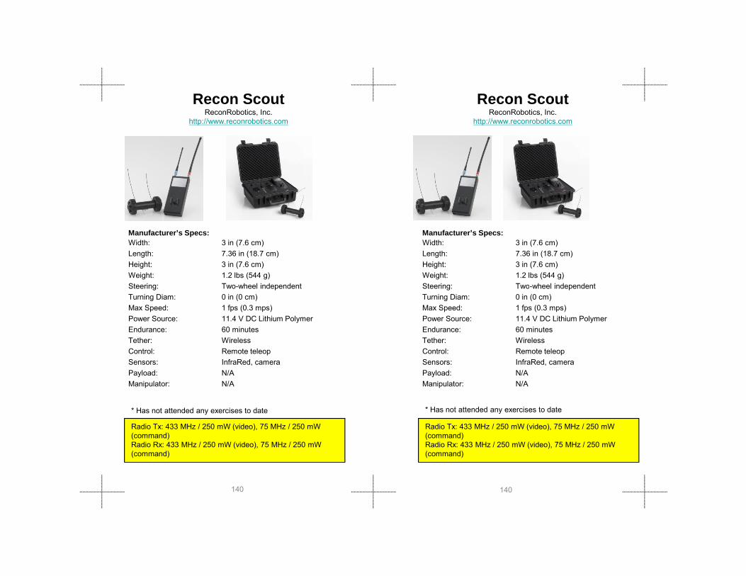
Recon ScoutReconRobotics, Inc.
http://www.reconrobotics.com
Manufacturer’s Specs:Width: 3 in (7.6 cm)Length: 7.36 in (18.7 cm)Height: 3 in (7.6 cm)Weight: 1.2 lbs (544 g)Steering: Two-wheel independent
Recon ScoutReconRobotics, Inc.
http://www.reconrobotics.com
Manufacturer’s Specs:Width: 3 in (7.6 cm)Length: 7.36 in (18.7 cm)Height: 3 in (7.6 cm)Weight: 1.2 lbs (544 g)Steering: Two-wheel independent
140140
Steering: Two wheel independentTurning Diam: 0 in (0 cm)Max Speed: 1 fps (0.3 mps) Power Source: 11.4 V DC Lithium Polymer Endurance: 60 minutesTether: WirelessControl: Remote teleopSensors: InfraRed, cameraPayload: N/AManipulator: N/A
Radio Tx: 433 MHz / 250 mW (video), 75 MHz / 250 mW (command)Radio Rx: 433 MHz / 250 mW (video), 75 MHz / 250 mW (command)
* Has not attended any exercises to date * Has not attended any exercises to date

Gro
und
Rob
ots
Gro
und
Rob
ots
EyeBall R1O.D.F. Optronicswww.odfopt.com
336-302-9309/ilanit Gedalyoviche
Manufacturer’s Specs:• Circumference 3.25 in (8.25 cm)• Weight: 1.25 lbs (.566kg)• Turning Diam: 0 in• Max Speed: rotates 4 RPM• Power Source: battery
EyeBall R1O.D.F. Optronicswww.odfopt.com
336-302-9309/ilanit Gedalyoviche
Manufacturer’s Specs:• Circumference 3.25 in (8.25 cm)• Weight: 1.25 lbs (.566kg)• Turning Diam: 0 in• Max Speed: rotates 4 RPM• Power Source: battery
141141
Radio Tx: 2400 MHz, 902-928MHz (RF)Radio Rx: 2400 MHz, 902-928MHz (RF)
Power Source: battery • Endurance: 3 hours • Tether: none• Control: eyes-on, remote teleop• Sensors: camera• Payload: N/A• Manipulator: N/A
Radio Tx: 2400 MHz, 902-928MHz (RF)Radio Rx: 2400 MHz, 902-928MHz (RF)
Power Source: battery • Endurance: 3 hours • Tether: none• Control: eyes-on, remote teleop• Sensors: camera• Payload: N/A• Manipulator: N/A
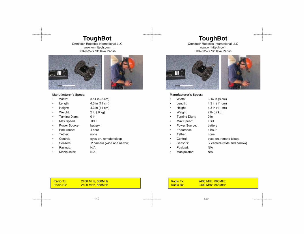
ToughBotOmnitech Robotics International LLC
www.omnitech.com303-922-7773/Dave Parish
Manufacturer’s Specs:• Width: 3.14 in (8 cm) • Length: 4.3 in (11 cm)• Height: 4.3 in (11 cm)• Weight: 2 lb (.9 kg)• Turning Diam: 0 in
ToughBotOmnitech Robotics International LLC
www.omnitech.com303-922-7773/Dave Parish
Manufacturer’s Specs:• Width: 3.14 in (8 cm) • Length: 4.3 in (11 cm)• Height: 4.3 in (11 cm)• Weight: 2 lb (.9 kg)• Turning Diam: 0 in
142142
Turning Diam: 0 in• Max Speed: TBD• Power Source: battery • Endurance: 1 hour• Tether: none• Control: eyes-on, remote teleop• Sensors: 2 camera (wide and narrow)• Payload: N/A• Manipulator: N/A
Radio Tx: 2400 MHz, 868MHz Radio Rx: 2400 MHz, 868MHz
Turning Diam: 0 in• Max Speed: TBD• Power Source: battery • Endurance: 1 hour• Tether: none• Control: eyes-on, remote teleop• Sensors: 2 camera (wide and narrow)• Payload: N/A• Manipulator: N/A
Radio Tx: 2400 MHz, 868MHz Radio Rx: 2400 MHz, 868MHz
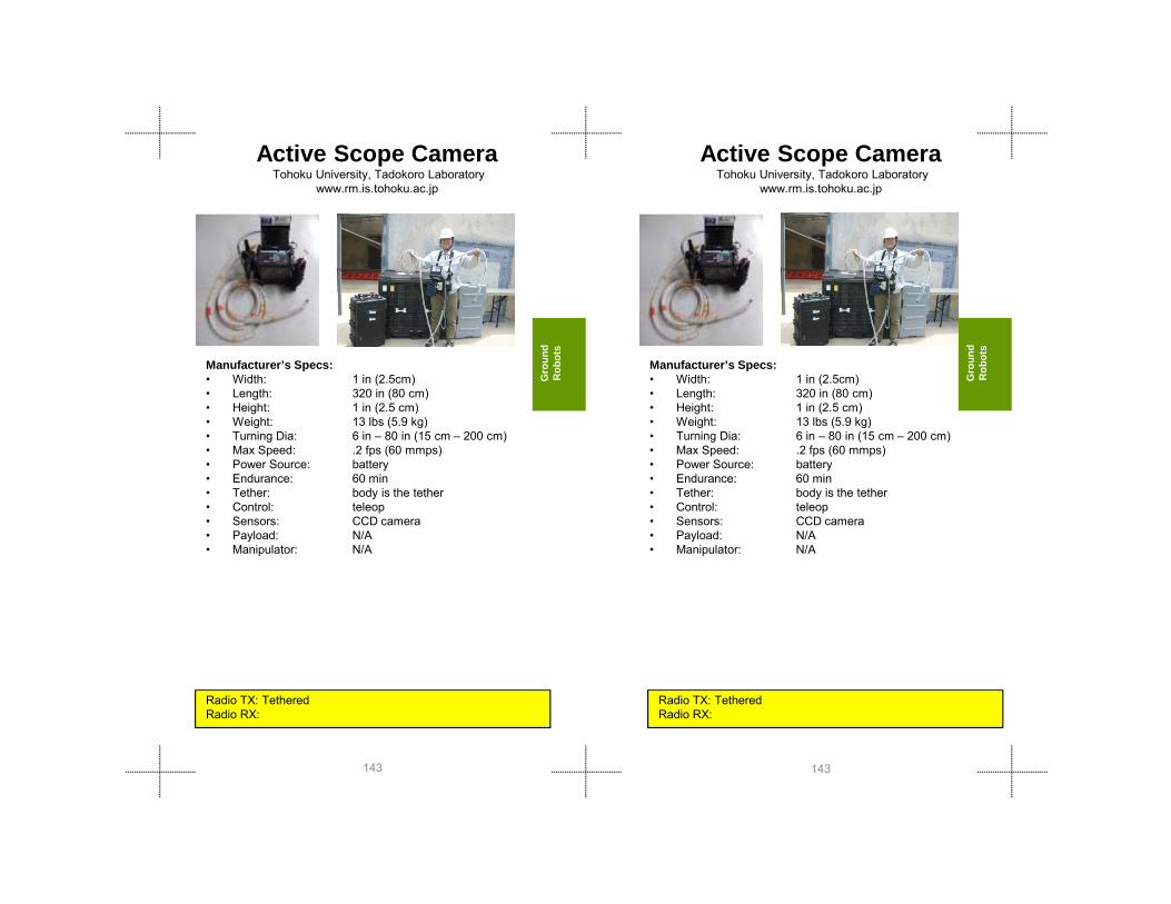
Gro
und
Rob
ots
Gro
und
Rob
ots
Active Scope Camera Tohoku University, Tadokoro Laboratory
www.rm.is.tohoku.ac.jp
Manufacturer’s Specs:• Width: 1 in (2.5cm)• Length: 320 in (80 cm)• Height: 1 in (2.5 cm)• Weight: 13 lbs (5.9 kg)• Turning Dia: 6 in – 80 in (15 cm – 200 cm)• Max Speed: 2 fps (60 mmps)
Active Scope Camera Tohoku University, Tadokoro Laboratory
www.rm.is.tohoku.ac.jp
Manufacturer’s Specs:• Width: 1 in (2.5cm)• Length: 320 in (80 cm)• Height: 1 in (2.5 cm)• Weight: 13 lbs (5.9 kg)• Turning Dia: 6 in – 80 in (15 cm – 200 cm)• Max Speed: 2 fps (60 mmps)
143143
Radio TX: TetheredRadio RX:
Max Speed: .2 fps (60 mmps)• Power Source: battery• Endurance: 60 min• Tether: body is the tether• Control: teleop• Sensors: CCD camera• Payload: N/A• Manipulator: N/A
Radio TX: TetheredRadio RX:
Max Speed: .2 fps (60 mmps)• Power Source: battery• Endurance: 60 min• Tether: body is the tether• Control: teleop• Sensors: CCD camera• Payload: N/A• Manipulator: N/A

Pointman (LRV)Applied Research Associates
www.ARA.com303-795-8106/Andrew Poulter
Manufacturer’s Specs:• Width: 20 in (51 cm)• Length: 14 in (36 cm)• Height: 6.5 in (16 cm)• Weight: 14 lbs (6.3 kg)• Turning Diam: 20 in (51 cm)• Max Speed: 6 fps (1 8 mps)
Pointman (LRV)Applied Research Associates
www.ARA.com303-795-8106/Andrew Poulter
Manufacturer’s Specs:• Width: 20 in (51 cm)• Length: 14 in (36 cm)• Height: 6.5 in (16 cm)• Weight: 14 lbs (6.3 kg)• Turning Diam: 20 in (51 cm)• Max Speed: 6 fps (1 8 mps)
144144
Radio Tx: 75MHz(75mW), 900 MHz(100mW),2400MHz(200mW)Radio Rx: 75 MHz , 900 MHz , 2400 MHz
Max Speed: 6 fps (1.8 mps) • Power Source: 8.5 AH Lithium Polymer • Endurance: 60-240 min • Tether: Option• Control: Remote tele-operation• Sensors: Color / IR Cameras• Payload: 1.2 lb(0.5 kg) , drag 20 lb (9 kg)• Manipulator: N/A –future option, existing
boom reach is 18 in (45 cm

Gro
und
Rob
ots
Gro
und
Rob
ots
VGTV-ExtremeInuktun
www.inuktun.com/1-877-468-5886/ Derek Naughton
Manufacturer’s Specs:• Width: 10.9 in (27.7 cm) • Length: 16.8 in (42.7 cm) • Height: 5.5 in (14 cm) Lowered• Weight: 14-20 lbs( 6.2-9.1kg )• Turning Diam: 0 in (0 cm)
VGTV-ExtremeInuktun
www.inuktun.com/1-877-468-5886/ Derek Naughton
Manufacturer’s Specs:• Width: 10.9 in (27.7 cm) • Length: 16.8 in (42.7 cm) • Height: 5.5 in (14 cm) Lowered• Weight: 14-20 lbs( 6.2-9.1kg )• Turning Diam: 0 in (0 cm)
145145
Turning Diam: 0 in (0 cm)• Max Speed: 1.5 fps (.45 mps) • Power Source: lithium ion battery• Endurance: >360 min• Tether: power, comms• Control: eyes-on, remote teleop• Sensors: tilt camera 300º• Payload: 10 lb (4.5 kg)• Manipulator: N/A
Radio Tx: (tether only)Radio Rx: (tether only)
Turning Diam: 0 in (0 cm)• Max Speed: 1.5 fps (.45 mps) • Power Source: lithium ion battery• Endurance: >360 min• Tether: power, comms• Control: eyes-on, remote teleop• Sensors: tilt camera 300º• Payload: 10 lb (4.5 kg)• Manipulator: N/A
Radio Tx: (tether only)Radio Rx: (tether only)

Dragon Runner SUGVQinetiq North America / Foster-Miller Inc
www.foster-miller.com/lemming.htm781-684-3960/Joanne Arms
Dragon Runner SUGVQinetiq North America / Foster-Miller Inc
www.foster-miller.com/lemming.htm781-684-3960
Manufacturer’s Specs:• Width: 12.2 in (31 cm)• Length: 16.6 in (42 cm)• Height: 6 in (15.2 cm) • Weight: 14 lbs (6.4 kg) • Turning Diam: Zero-Turn; Swept • Max Speed: 7 5 - 29 fps (5 - 20 mph)
Manufacturer’s Specs:• Width: 12.2 in (31 cm)• Length: 16.6 in (42 cm)• Height: 6 in (15.2 cm) • Weight: 14 lbs (6.4 kg) • Turning Diam: Zero-Turn; Swept • Max Speed: 7 5 - 29 fps (5 - 20 mph)
146146
Radio Tx: Low S-Band MHz(1 – 1k mW)L-Band MHz (1–1K mW)Radio Rx: n/a
Radio Tx: Low S-Band MHz(1 – 1k mW)L-Band MHz (1–1K mW)Radio Rx: n/a
Max Speed: 7.5 29 fps (5 20 mph)• Power Source: battery (Li Ion)• Endurance: 2 hours mph on flat ground • Tether: none• Control: remote teleop, loss-of-comms
back-tracking, cruise-control• Sensors: thermal (PIR), acoustic, visual
(wide-angle FF lens; IR illuminator)• Payload: 10 lb (4.5 kg)• Manipulator: 2 or 3 degree of motion w/gripper
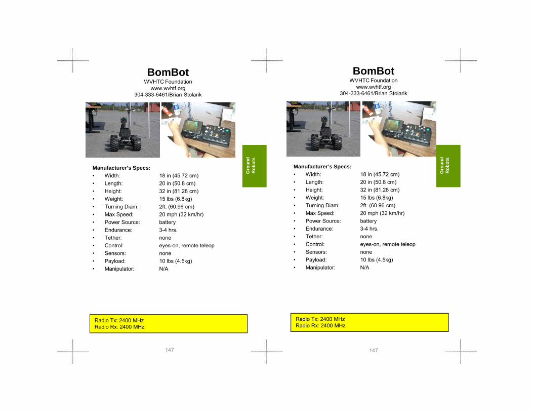
Gro
und
Rob
ots
Gro
und
Rob
ots
BomBotWVHTC Foundation
www.wvhtf.org304-333-6461/Brian Stolarik
Manufacturer’s Specs:• Width: 18 in (45.72 cm)• Length: 20 in (50.8 cm)• Height: 32 in (81.28 cm)• Weight: 15 lbs (6.8kg) • Turning Diam: 2ft (60 96 cm)
BomBotWVHTC Foundation
www.wvhtf.org304-333-6461/Brian Stolarik
Manufacturer’s Specs:• Width: 18 in (45.72 cm)• Length: 20 in (50.8 cm)• Height: 32 in (81.28 cm)• Weight: 15 lbs (6.8kg) • Turning Diam: 2ft (60 96 cm)
147147
Turning Diam: 2ft. (60.96 cm)• Max Speed: 20 mph (32 km/hr)• Power Source: battery • Endurance: 3-4 hrs.• Tether: none• Control: eyes-on, remote teleop• Sensors: none• Payload: 10 lbs (4.5kg)• Manipulator: N/A
Radio Tx: 2400 MHz Radio Rx: 2400 MHz
• Turning Diam: 2ft. (60.96 cm)• Max Speed: 20 mph (32 km/hr)• Power Source: battery • Endurance: 3-4 hrs.• Tether: none• Control: eyes-on, remote teleop• Sensors: none• Payload: 10 lbs (4.5kg)• Manipulator: N/A
Radio Tx: 2400 MHz Radio Rx: 2400 MHz
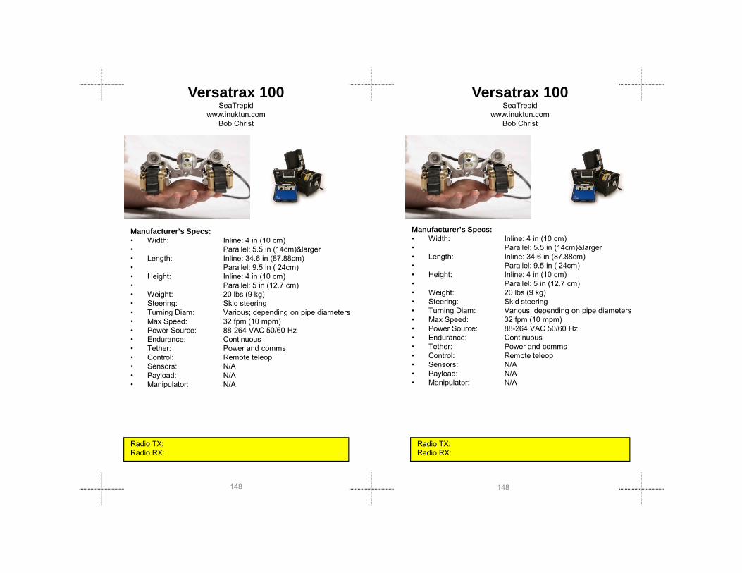
Versatrax 100SeaTrepid
www.inuktun.comBob Christ
Manufacturer’s Specs:• Width: Inline: 4 in (10 cm)• Parallel: 5.5 in (14cm)&larger • Length: Inline: 34.6 in (87.88cm)• Parallel: 9.5 in ( 24cm)• Height: Inline: 4 in (10 cm)• Parallel: 5 in (12.7 cm)
Versatrax 100SeaTrepid
www.inuktun.comBob Christ
Manufacturer’s Specs:• Width: Inline: 4 in (10 cm) • Parallel: 5.5 in (14cm)&larger • Length: Inline: 34.6 in (87.88cm)• Parallel: 9.5 in ( 24cm)• Height: Inline: 4 in (10 cm)• Parallel: 5 in (12 7 cm)
148148
( )• Weight: 20 lbs (9 kg)• Steering: Skid steering• Turning Diam: Various; depending on pipe diameters• Max Speed: 32 fpm (10 mpm) • Power Source: 88-264 VAC 50/60 Hz• Endurance: Continuous• Tether: Power and comms• Control: Remote teleop• Sensors: N/A• Payload: N/A• Manipulator: N/A
Radio TX:Radio RX:
Parallel: 5 in (12.7 cm)• Weight: 20 lbs (9 kg)• Steering: Skid steering• Turning Diam: Various; depending on pipe diameters• Max Speed: 32 fpm (10 mpm) • Power Source: 88-264 VAC 50/60 Hz• Endurance: Continuous• Tether: Power and comms• Control: Remote teleop• Sensors: N/A• Payload: N/A• Manipulator: N/A
Radio TX: Radio RX:

Gro
und
Rob
ots
Gro
und
Rob
ots
G2BotMesa Robotics, Inc.
www.mesa-robotics.com256.258.2130/Toki Owens
G2BotMesa Robotics, Inc.
www.mesa-robotics.com256.258.2130/Toki Owens
Manufacturer’s Specs:• Width: 13.5 in (34.29 cm)• Length: 21 in (53.34 cm)• Height: 12 in (30.48 cm)• Weight: 25 lbs (11.33 kg)• Turning Dia: 21 in (53.34 cm)• Max Speed: 4 mph (6 4 km/hr)
Manufacturer’s Specs:• Width: 13.5 in (34.29 cm)• Length: 21 in (53.34 cm)• Height: 12 in (30.48 cm)• Weight: 25 lbs (11.33 kg)• Turning Dia: 21 in (53.34 cm)• Max Speed: 4 mph (6 4 km/hr)
149149
Radio TX: 900 MHz control, 2400 MHz videoRadio RX: 900 MHz control, 2400 MHz video
Max Speed: 4 mph (6.4 km/hr)• Power Source: 12VDC, NiMH battery• Endurance: 60 – 120 min• Tether: none• Control: rf 700 meters• Sensors: Cameras• Payload: 15 lbs (6.80 kg)• Manipulator: none
Radio TX: 900 MHz control, 2400 MHz videoRadio RX: 900 MHz control, 2400 MHz video
Max Speed: 4 mph (6.4 km/hr)• Power Source: 12VDC, NiMH battery• Endurance: 60 – 120 min• Tether: none• Control: rf 700 meters• Sensors: Cameras• Payload: 15 lbs (6.80 kg)• Manipulator: none
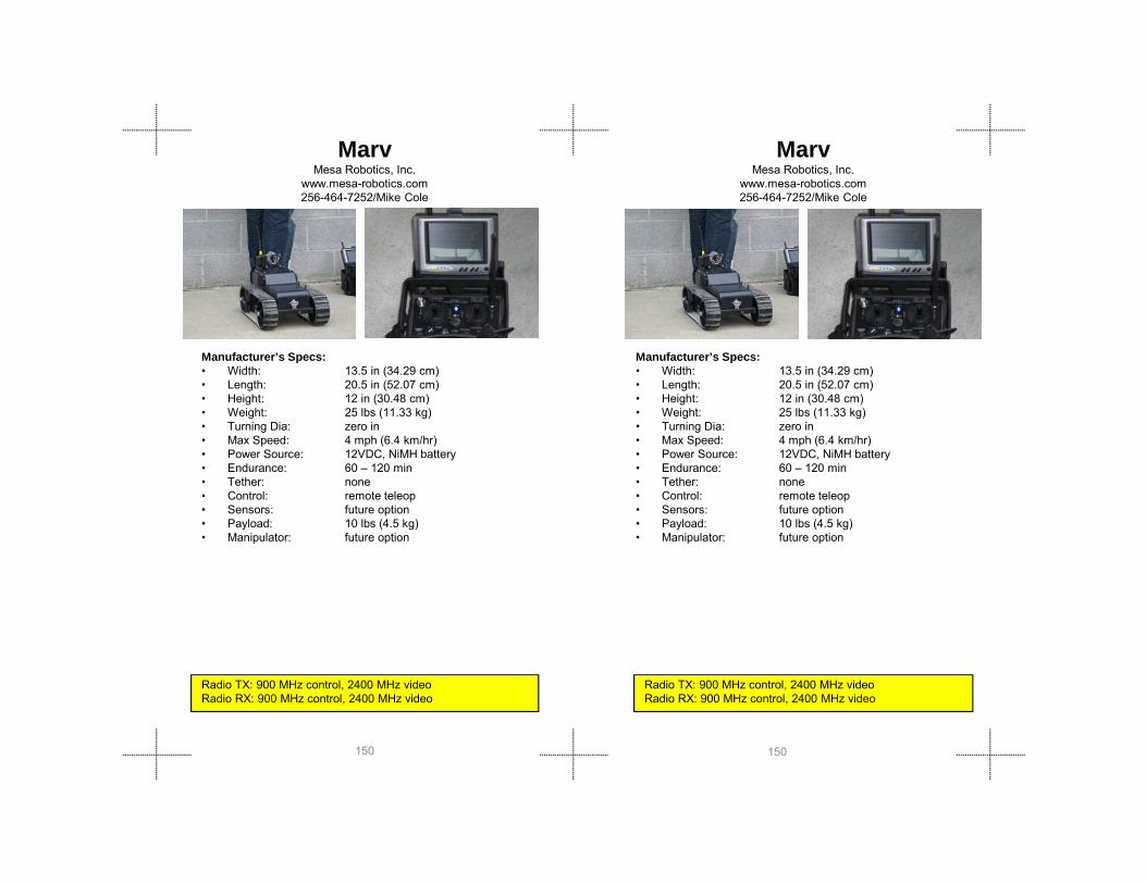
MarvMesa Robotics, Inc.
www.mesa-robotics.com256-464-7252/Mike Cole
Manufacturer’s Specs:• Width: 13.5 in (34.29 cm)• Length: 20.5 in (52.07 cm)• Height: 12 in (30.48 cm)• Weight: 25 lbs (11.33 kg)• Turning Dia: zero in• Max Speed: 4 mph (6 4 km/hr)
MarvMesa Robotics, Inc.
www.mesa-robotics.com256-464-7252/Mike Cole
Manufacturer’s Specs:• Width: 13.5 in (34.29 cm)• Length: 20.5 in (52.07 cm)• Height: 12 in (30.48 cm)• Weight: 25 lbs (11.33 kg)• Turning Dia: zero in• Max Speed: 4 mph (6 4 km/hr)
150150
Max Speed: 4 mph (6.4 km/hr)• Power Source: 12VDC, NiMH battery• Endurance: 60 – 120 min• Tether: none• Control: remote teleop• Sensors: future option• Payload: 10 lbs (4.5 kg)• Manipulator: future option
Radio TX: 900 MHz control, 2400 MHz videoRadio RX: 900 MHz control, 2400 MHz video
Max Speed: 4 mph (6.4 km/hr)• Power Source: 12VDC, NiMH battery• Endurance: 60 – 120 min• Tether: none• Control: remote teleop• Sensors: future option• Payload: 10 lbs (4.5 kg)• Manipulator: future option
Radio TX: 900 MHz control, 2400 MHz videoRadio RX: 900 MHz control, 2400 MHz video

Gro
und
Rob
ots
Gro
und
Rob
ots
Souryu IVInternational Rescue System Institute
www.rescuesystem.orgShigeo Hirose
Manufacturer’s Specs:• Width: 5.9 in (16 cm)• Length: 47.2 in (121 cm)• Height: 5.1 in (13 cm)• Weight: 28.6 lbs (112 kg)• Turning Diam: 1 0 m
Souryu IVInternational Rescue System Institute
www.rescuesystem.orgShigeo Hirose
Manufacturer’s Specs:• Width: 5.9 in (16 cm)• Length: 47.2 in (121 cm)• Height: 5.1 in (13 cm)• Weight: 28.6 lbs (112 kg)• Turning Diam: 1 0 m
151151
Radio Tx: (tether only)Radio Rx: (tether only)
Turning Diam: 1.0 m• Max Speed: 370mm/sec• Power Source: battery• Endurance: • Tether: comms• Control: remote teleop• Sensors: camera• Payload: none• Manipulator: none
Radio Tx: (tether only)Radio Rx: (tether only)
Turning Diam: 1.0 m• Max Speed: 370mm/sec• Power Source: battery• Endurance: • Tether: comms• Control: remote teleop• Sensors: camera• Payload: none• Manipulator: none

SouryuInternational Rescue System Institute
www.rescuesystem.orgShigeo Hirose
Manufacturer’s Specs:• Width: 5.9 in (15 cm)• Length: 47.2 in (120 cm)• Height: 5.1 in (13 cm)• Weight: 28.6 lbs (13 kg)• Turning Diam: 1 0 m
SouryuInternational Rescue System Institute
www.rescuesystem.orgShigeo Hirose
Manufacturer’s Specs:• Width: 5.9 in (15 cm)• Length: 47.2 in (120 cm)• Height: 5.1 in (13 cm)• Weight: 28.6 lbs (13 kg)• Turning Diam: 1 0 m
152152
Turning Diam: 1.0 m• Max Speed: 0.3 mps• Power Source: battery• Endurance: 20 min• Tether: comms• Control: remote teleop• Sensors: thermal, camera, GAS(CO, O2,
SO, CH)• Payload: none• Manipulator: none
Radio Tx: (tether only)Radio Rx: (tether only)
Turning Diam: 1.0 m• Max Speed: 0.3 mps• Power Source: battery• Endurance: 20 min• Tether: comms• Control: remote teleop• Sensors: thermal, camera, GAS(CO, O2,
SO, CH)• Payload: none• Manipulator: none
Radio Tx: (tether only)Radio Rx: (tether only)
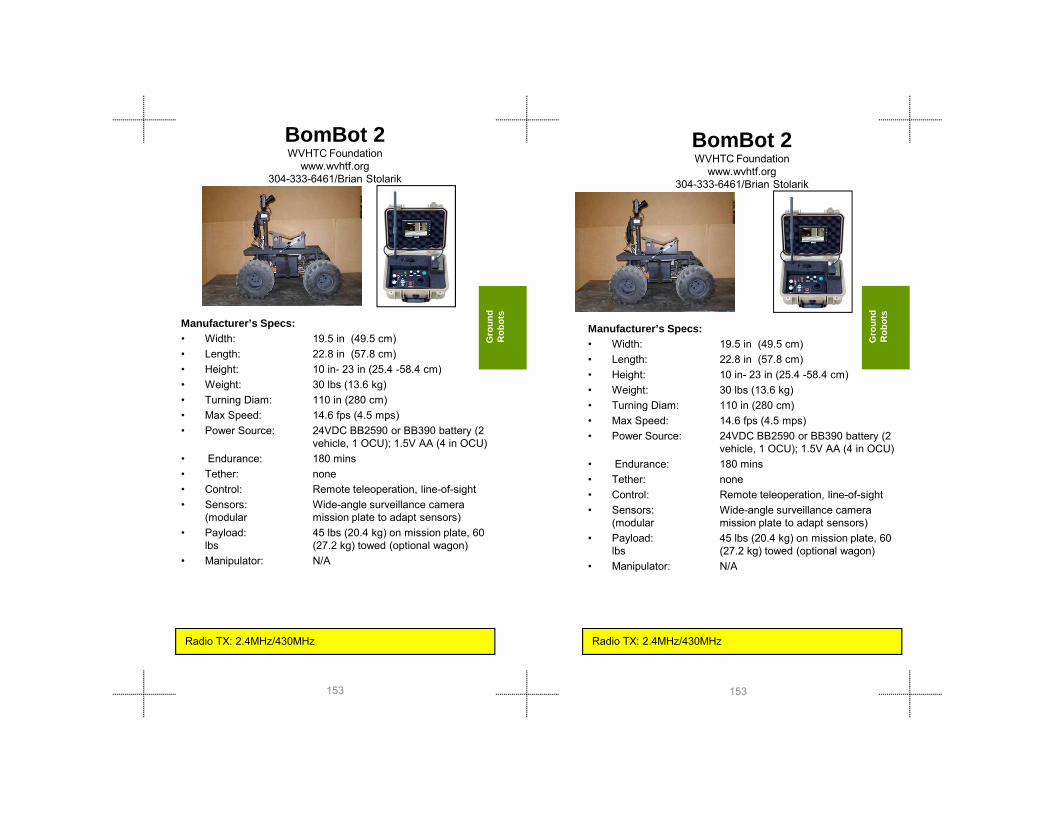
Gro
und
Rob
ots
Gro
und
Rob
ots
BomBot 2WVHTC Foundation
www.wvhtf.org304-333-6461/Brian Stolarik
Manufacturer’s Specs:• Width: 19.5 in (49.5 cm)• Length: 22.8 in (57.8 cm)• Height: 10 in- 23 in (25.4 -58.4 cm) • Weight: 30 lbs (13.6 kg) • Turning Diam: 110 in (280 cm)
BomBot 2WVHTC Foundation
www.wvhtf.org304-333-6461/Brian Stolarik
Manufacturer’s Specs:• Width: 19.5 in (49.5 cm)• Length: 22.8 in (57.8 cm)• Height: 10 in- 23 in (25.4 -58.4 cm) • Weight: 30 lbs (13.6 kg) • Turning Diam: 110 in (280 cm)
153153
Turning Diam: 110 in (280 cm)• Max Speed: 14.6 fps (4.5 mps) • Power Source: 24VDC BB2590 or BB390 battery (2
vehicle, 1 OCU); 1.5V AA (4 in OCU)• Endurance: 180 mins• Tether: none• Control: Remote teleoperation, line-of-sight• Sensors: Wide-angle surveillance camera
(modular mission plate to adapt sensors)• Payload: 45 lbs (20.4 kg) on mission plate, 60
lbs (27.2 kg) towed (optional wagon)• Manipulator: N/A
• Max Speed: 14.6 fps (4.5 mps) • Power Source: 24VDC BB2590 or BB390 battery (2
vehicle, 1 OCU); 1.5V AA (4 in OCU)• Endurance: 180 mins• Tether: none• Control: Remote teleoperation, line-of-sight• Sensors: Wide-angle surveillance camera
(modular mission plate to adapt sensors)• Payload: 45 lbs (20.4 kg) on mission plate, 60
lbs (27.2 kg) towed (optional wagon)• Manipulator: N/A
Radio TX: 2.4MHz/430MHz Radio TX: 2.4MHz/430MHz
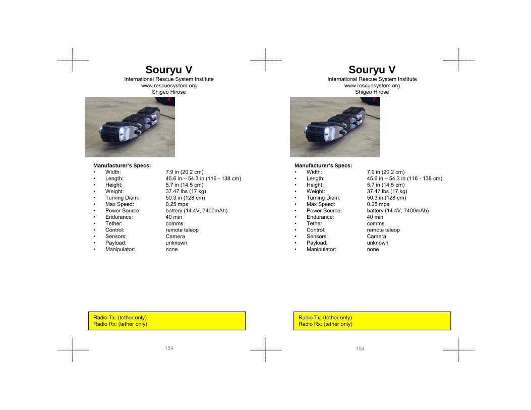
Manufacturer’s Specs:• Width: 7.9 in (20.2 cm)• Length: 45.6 in – 54.3 in (116 - 138 cm)• Height: 5.7 in (14.5 cm)• Weight: 37.47 lbs (17 kg)• Turning Diam: 50.3 in (128 cm)• Max Speed: 0 25 mps
Souryu VInternational Rescue System Institute
www.rescuesystem.orgShigeo Hirose
Manufacturer’s Specs:• Width: 7.9 in (20.2 cm)• Length: 45.6 in – 54.3 in (116 - 138 cm)• Height: 5.7 in (14.5 cm)• Weight: 37.47 lbs (17 kg)• Turning Diam: 50.3 in (128 cm)• Max Speed: 0 25 mps
Souryu VInternational Rescue System Institute
www.rescuesystem.orgShigeo Hirose
154154
Max Speed: 0.25 mps• Power Source: battery (14.4V, 7400mAh) • Endurance: 40 min• Tether: comms• Control: remote teleop• Sensors: Camera• Payload: unknown• Manipulator: none
Radio Tx: (tether only)Radio Rx: (tether only)
Max Speed: 0.25 mps• Power Source: battery (14.4V, 7400mAh) • Endurance: 40 min• Tether: comms• Control: remote teleop• Sensors: Camera• Payload: unknown• Manipulator: none
Radio Tx: (tether only)Radio Rx: (tether only)

Gro
und
Rob
ots
Gro
und
Rob
ots
Jacobs Rugged RobotJacobs University, Robotics Group, Bremen, Germany
http://robotics.jacobs-university.deProf. Dr. Andreas Birk
Jacobs Rugged RobotJacobs University, Robotics Group, Bremen, Germany
http://robotics.jacobs-university.deProf. Dr. Andreas Birk
Manufacturer’s Specs:Width: 20.31 in (51.6 cm)Length: 21.06 in (53.5 cm) -37.20 in (94.5
cm)Height: 19.69 in (50 cm)Weight: 39.68 lbs (18 kg)
Manufacturer’s Specs:Width: 20.31 in (51.6 cm)Length: 21.06 in (53.5 cm) -37.20 in (94.5
cm)Height: 19.69 in (50 cm)Weight: 39.68 lbs (18 kg)
155155
Radio Tx: 802.11 bg / a (2.4 GHz / 5.0 GHz) Radio Rx: 802.11 bg / a (2.4 GHz / 5.0 GHz)
e g t 39 68 bs ( 8 g)Steering: skidTurning Diam: 0Max Speed: 2.8 m/s (10.1 Km/h) Power Source: LiPo Batteries, 173 WhEndurance: 2 hoursTether: optional, solely for communicationControl: autonomous/teleoperation Sensors: Hokuyo/Sick /FLIR Payload: 55.12 lbs (25kg)Manipulator: optional Neuronics Katana arm (6
DOF, 37.4 in (95 cm) reach)
Radio Tx: 802.11 bg / a (2.4 GHz / 5.0 GHz) Radio Rx: 802.11 bg / a (2.4 GHz / 5.0 GHz)

ElementMesa Robotics, Inc.
www.mesa-robotics.com256-258-2130/Don Jones
Manufacturer’s Specs:• Width: 21 in (53.34 cm)• Length: 30 in (76.2cm)• Height: 12 in (30.48 cm)• Weight: 40 lbs (18 kg)• Turning Dia: zero
ElementMesa Robotics, Inc.
www.mesa-robotics.com256-258-2130/Don Jones
Manufacturer’s Specs:• Width: 21 in (53.34 cm)• Length: 30 in (76.2cm)• Height: 12 in (30.48 cm)• Weight: 40 lbs (18 kg)• Turning Dia: zero
M S d 2 0 h
156156
Radio TX: 900 MHz control, 1800 MHz video, 469 MHz audioRadio RX: 900 MHz control, 1800 MHz video, 469 MHz audio
Radio TX: 900 MHz control, 1800 MHz video, 469 MHz audioRadio RX: 900 MHz control, 1800 MHz video, 469 MHz audio
g• Max Speed: 2.0 mph• Power Source: 12VCD battery, NiMH• Endurance: 360 – 480 min• Tether: fiber optic cable (data,video, audio)• Control: remote teleop• Sensors: biological, chemical, radiological• Payload: 125 lbs• Manipulator: 5 DOF with 44 in reach (adds
45lbs/20.4kg to weight)
• Max Speed: 2.0 mph• Power Source: 12VCD battery, NiMH• Endurance: 360 – 480 min• Tether: fiber optic cable (data,video, audio)• Control: remote teleop• Sensors: biological, chemical, radiological• Payload: 125 lbs• Manipulator: 5 DOF with 44 in reach (adds
45lbs/20.4kg to weight)

Gro
und
Rob
ots
Gro
und
Rob
ots
Manufacturer’s Specs:
• Width: 21 in (53 cm)• Length: 36 in (91 cm)• Height: 17 in (43 cm)• Weight: 42 lbs (19 kg)• Turning Diam: 0 m (0 cm)
HeroFirst-Response Robotics, LLC
www.FirstResponseRobotics.com513-752-6653 /Mike Cardarelli
Manufacturer’s Specs:
• Width: 21 in (53 cm)• Length: 36 in (91 cm)• Height: 17 in (43 cm)• Weight: 42 lbs (19 kg)• Turning Diam: 0 m (0 cm)
HeroFirst-Response Robotics, LLC
www.FirstResponseRobotics.com513-752-6653 /Mike Cardarelli
157157
Turning Diam: 0 m (0 cm)• Max Speed: 10 fps (3 mps)• Power Source: battery• Endurance: 45 min• Tether: none• Control: remote teleop• Sensors: radiation, biological• Payload: 130 lb (59 kg)• Manipulator: none
Radio TX: 72 MHz controller/1.0W (video), 2.4 MHz900 MHz/0.5 W (telemetry), 1.2 MHz / 3W (video)

Super Kenaf International Rescue System Institute
www.rescuesystem.orgEiji Koyanagi
Manufacturer’s Specs:Width: 16.9 in (43.0 cm)Length: 37.0 (20.4)in (94.0(52.0) cm)Height: 6.3 in (16.0 cm)Weight: 43.3 lbs (19.0 kg)Steering: skid
Super Kenaf International Rescue System Institute
www.rescuesystem.orgEiji Koyanagi
Manufacturer’s Specs:Width: 16.9 in (43.0 cm)Length: 37.0 (20.4)in (94.0(52.0) cm)Height: 6.3 in (16.0 cm)Weight: 43.3 lbs (19.0 kg)Steering: skid
158158
Radio Tx: 802.11ARadio Rx: 802.11A
Stee g s dTurning Diam: diagonal for skid steer 0 in (0 cm)Max Speed: 11.6 fps (3.5 mps) Power Source: batteryEndurance: 40 minTether: noneControl: remote teleopSensors: NonePayload: NoneManipulator: None
Radio Tx: 802.11ARadio Rx: 802.11A
Turning Diam: diagonal for skid steer 0 in (0 cm)Max Speed: 11.6 fps (3.5 mps) Power Source: batteryEndurance: 40 minTether: noneControl: remote teleopSensors: NonePayload: NoneManipulator: None
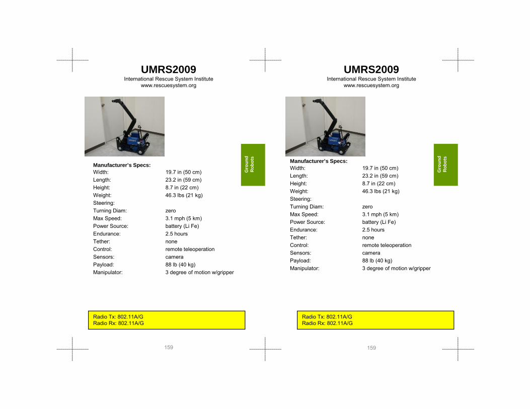
Gro
und
Rob
ots
Gro
und
Rob
ots
Manufacturer’s Specs:Width: 19.7 in (50 cm) Length: 23.2 in (59 cm)Height: 8.7 in (22 cm)Weight: 46.3 lbs (21 kg)Steering:
UMRS2009International Rescue System Institute
www.rescuesystem.org
Manufacturer’s Specs:Width: 19.7 in (50 cm) Length: 23.2 in (59 cm)Height: 8.7 in (22 cm)Weight: 46.3 lbs (21 kg)Steering:T i Di
UMRS2009International Rescue System Institute
www.rescuesystem.org
159159
Stee gTurning Diam: zeroMax Speed: 3.1 mph (5 km)Power Source: battery (Li Fe)Endurance: 2.5 hoursTether: noneControl: remote teleoperationSensors: cameraPayload: 88 lb (40 kg)Manipulator: 3 degree of motion w/gripper
Radio Tx: 802.11A/GRadio Rx: 802.11A/G
Turning Diam: zeroMax Speed: 3.1 mph (5 km)Power Source: battery (Li Fe)Endurance: 2.5 hoursTether: noneControl: remote teleoperationSensors: cameraPayload: 88 lb (40 kg)Manipulator: 3 degree of motion w/gripper
Radio Tx: 802.11A/GRadio Rx: 802.11A/G

Kenaf International Rescue System Institute
www.rescuesystem.orgEiji Koyanagi
Manufacturer’s Specs:Width: 16.9 in (43.0 cm)Length: 37.0 (20.4)in (94.0(52.0) cm)Height: 7.7 in (19.5 cm)Weight: 48.9 lbs (22.0 kg)Steering: skid
Kenaf International Rescue System Institute
www.rescuesystem.orgEiji Koyanagi
Manufacturer’s Specs:Width: 16.9 in (43.0 cm)Length: 37.0 (20.4)in (94.0(52.0) cm)Height: 7.7 in (19.5 cm)Weight: 48.9 lbs (22.0 kg)Steering: skid
160160
Radio Tx: 802.11ARadio Rx: 802.11A
Stee g s dTurning Diam: diagonal for skid steer 0 in (0 cm)Max Speed: 1.2 fps (0.4 mps) Power Source: batteryEndurance: 120 minTether: noneControl: remote teleoperationSensors: CCD Camera, Fisheye Camera, 3D
Scanner ( 2D URG + Pant Tilt base)Payload: NoneManipulator: None
Radio Tx: 802.11ARadio Rx: 802.11A
Turning Diam: diagonal for skid steer 0 in (0 cm)Max Speed: 1.2 fps (0.4 mps) Power Source: batteryEndurance: 120 minTether: noneControl: remote teleoperationSensors: CCD Camera, Fisheye Camera, 3D
Scanner ( 2D URG + Pant Tilt base)Payload: NoneManipulator: None

Gro
und
Rob
ots
Gro
und
Rob
ots
PackBot ExploreriRobot
www.irobot.com781-345-0200/Jeff Ostazewski
Manufacturer’s Specs:• Width: 16 in - 20 in (40 - 50 cm)• Length: 27 in(69 cm) • Height: 7.5 in (19 cm)• Weight: 48 lbs (22 kg)• Turning Dia: 34 in (86.36 cm)• Max Speed: Variable 0 - 5 mph (0 - 8 km/hr)
PackBot ExploreriRobot
www.irobot.com781-345-0200/Jeff Ostazewski
Manufacturer’s Specs:• Width: 16 in - 20 in (40 - 50 cm)• Length: 27 in(69 cm) • Height: 7.5 in (19 cm)• Weight: 48 lbs (22 kg)• Turning Dia: 34 in (86.36 cm)
161161
Max Speed: Variable 0 - 5 mph (0 - 8 km/hr)• Power Source: battery• Endurance: 2-12 hours / 6+ mi (10+ km)• Tether: optional• Control: Teleop• Sensors: Zoom & FLIR cameras, omni dirc mic• Payload: Supports up to 8 • Manipulator: surveillance head is mounted on a
12 in (.3m) mast with a 360° pan and 270° tilt
Radio TX: 2400 MHz Radio RX: 2400 MHz
• Max Speed: Variable 0 - 5 mph (0 - 8 km/hr)• Power Source: battery• Endurance: 2-12 hours / 6+ mi (10+ km)• Tether: optional• Control: Teleop• Sensors: Zoom & FLIR cameras, omni dirc mic• Payload: Supports up to 8 • Manipulator: surveillance head is mounted on a
12 in (.3m) mast with a 360° pan and 270° tilt
Radio TX: 2400 MHz Radio RX: 2400 MHz

Hibiscus Toin University of Yokohama Chiba Institute of Technology
Manufacturer’s Specs:• Width: 14.5 in (37 cm) • Length: 38.5 in (98 cm) • Height: 7 in (18 cm) • Weight: 49.6 lbs (22.5 kg)• Turn Diam: diagonal for skid steer
Hibiscus Toin University of Yokohama Chiba Institute of Technology
Manufacturer’s Specs:• Width: 14.5 in (37 cm) • Length: 38.5 in (98 cm) • Height: 7 in (18 cm) • Weight: 49.6 lbs (22.5 kg)• Turn Diam: diagonal for skid steer
162162
• Max Speed: .7 mph (1.2 km/ph)• Power Source: battery • Endurance: 60 min• Tether: none• Control Features: diagnostics, wall following,
centering• Sensors: URG,Heat, Voice • Payload: none• Manipulator: Sensor arm 4DOF: Length: 14.1 in
(36cm)
Radio TX: 2400 MHzRadio RX: 2400 MHz
Turn Diam: diagonal for skid steer• Max Speed: .7 mph (1.2 km/ph)• Power Source: battery • Endurance: 60 min• Tether: none• Control Features: diagnostics, wall following,
centering• Sensors: URG,Heat, Voice • Payload: none• Manipulator: Sensor arm 4DOF: Length: 14.1 in
(36cm)
Radio TX: 2400 MHzRadio RX: 2400 MHz

Gro
und
Rob
ots
Gro
und
Rob
ots
CpheaToin University of Yokohama Chiba Institute of Technology
Manufacturer’s Specs:• Width: 20 in (52 cm) • Length: 40 in (102 cm) • Height: 9.4 in (24 cm) • Weight: 49.6 lbs (22.5 kg)• Turn Diam: diagonal for skid steer
CpheaToin University of Yokohama Chiba Institute of Technology
Manufacturer’s Specs:• Width: 20 in (52 cm) • Length: 40 in (102 cm) • Height: 9.4 in (24 cm) • Weight: 49.6 lbs (22.5 kg)• Turn Diam: diagonal for skid steer
163163
• Max Speed: .37 mph (0.6 km/ph)• Power Source: battery • Endurance: 60 min• Tether: none• Control: diagnostics, wall following, centering• Sensors: URG,Heat, Voice • Payload: none• Manipulator: Sensor arm 2DOF: Length (30cm)
Radio TX: 2400 MHzRadio RX: 2400 MHz
Turn Diam: diagonal for skid steer • Max Speed: .37 mph (0.6 km/ph)• Power Source: battery • Endurance: 60 min• Tether: none• Control: diagnostics, wall following, centering• Sensors: URG,Heat, Voice • Payload: none• Manipulator: Sensor arm 2DOF: Length (30cm)
Radio TX: 2400 MHzRadio RX: 2400 MHz
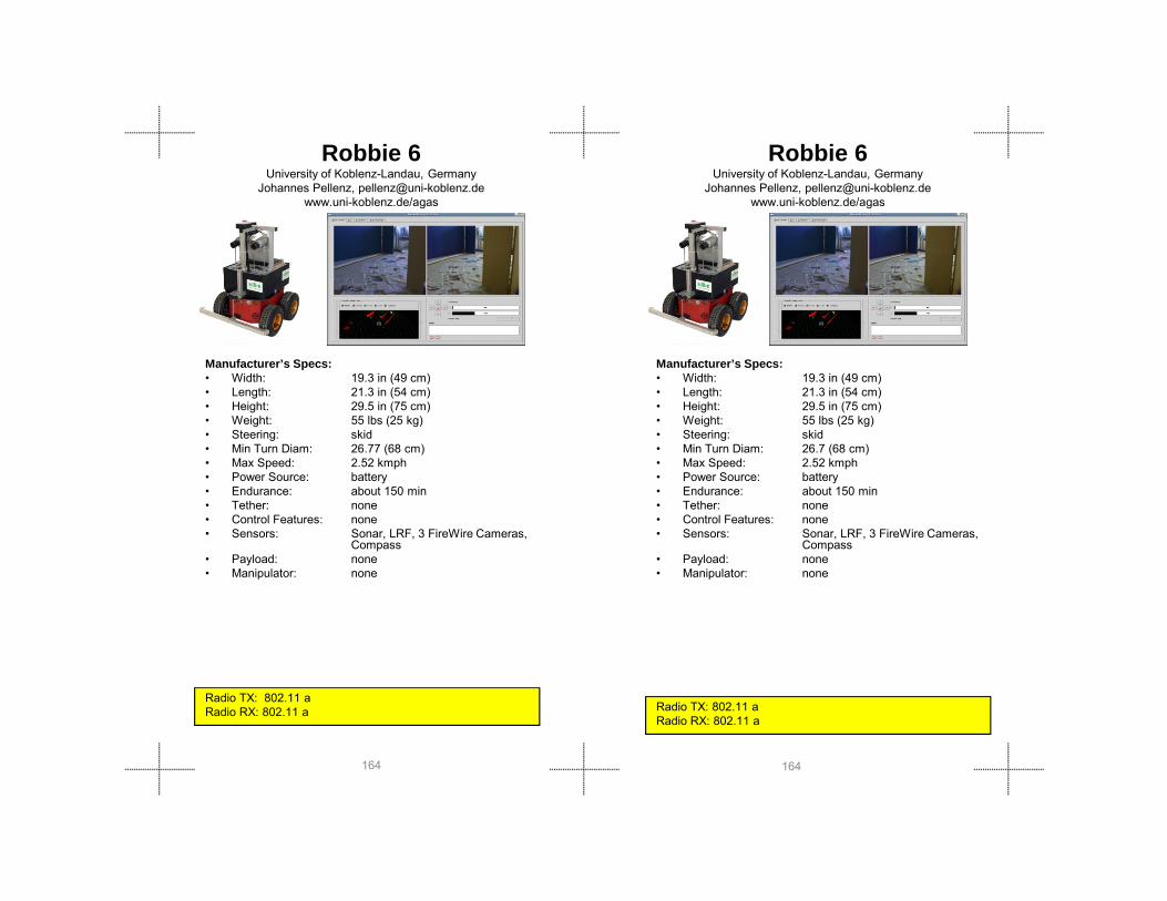
Robbie 6University of Koblenz-Landau, Germany
Johannes Pellenz, [email protected]/agas
Robbie 6University of Koblenz-Landau, Germany
Johannes Pellenz, [email protected]/agas
Manufacturer’s Specs:• Width: 19.3 in (49 cm)• Length: 21.3 in (54 cm)• Height: 29.5 in (75 cm)• Weight: 55 lbs (25 kg)• Steering: skid• Min Turn Diam: 26 77 (68 cm)
Manufacturer’s Specs:• Width: 19.3 in (49 cm)• Length: 21.3 in (54 cm)• Height: 29.5 in (75 cm)• Weight: 55 lbs (25 kg)• Steering: skid• Min Turn Diam: 26 7 (68 cm)
164164
Radio TX: 802.11 aRadio RX: 802.11 a
Min Turn Diam: 26.77 (68 cm)• Max Speed: 2.52 kmph• Power Source: battery • Endurance: about 150 min• Tether: none• Control Features: none• Sensors: Sonar, LRF, 3 FireWire Cameras,
Compass• Payload: none• Manipulator: none
Radio TX: 802.11 aRadio RX: 802.11 a
Min Turn Diam: 26.7 (68 cm)• Max Speed: 2.52 kmph• Power Source: battery • Endurance: about 150 min• Tether: none• Control Features: none• Sensors: Sonar, LRF, 3 FireWire Cameras,
Compass• Payload: none• Manipulator: none

Gro
und
Rob
ots
Gro
und
Rob
ots
ShinobiUniv Electo-Communications
www.hi.mce.uec.ac.jp/matsuno-lab/matsuno_eng.htmlNoritaka Sato
Manufacturer’s Specs:• Width: 15. 74 in (40 cm)• Length: 31.49 in (80 cm)• Height: 15-74 in – 31.49 in (40cm- 80cm)• Weight: 57.32 lbs (26 kg)• Turning Dia: 0• Max Speed: 21 mps ( 33 kms)
ShinobiUniv Electo-Communications
www.hi.mce.uec.ac.jp/matsuno-lab/matsuno_eng.htmlNoritaka Sato
Manufacturer’s Specs:• Width: 15. 74 in (40 cm)• Length: 31.49 in (80 cm)• Height: 15-74 in – 31.49 in (40cm- 80cm)• Weight: 57.32 lbs (26 kg)• Turning Dia: 0• Max Speed: 21 mps ( 33 kms)
165165
Max Speed: .21 mps (.33 kms)• Power Source: battery• Endurance: 60 min• Tether: none• Control: teleop• Sensors: thermal , chemical (cO2)• Payload: none• Manipulator: none
Radio TX: 5200 MhZ (10mW)Radio RX: 5200 MhZ (10mW)
Max Speed: .21 mps (.33 kms)• Power Source: battery• Endurance: 60 min• Tether: none• Control: teleop• Sensors: thermal , chemical (cO2)• Payload: none• Manipulator: none
Radio TX: 5200 MhZ (10mW)Radio RX: 5200 MhZ (10mW)
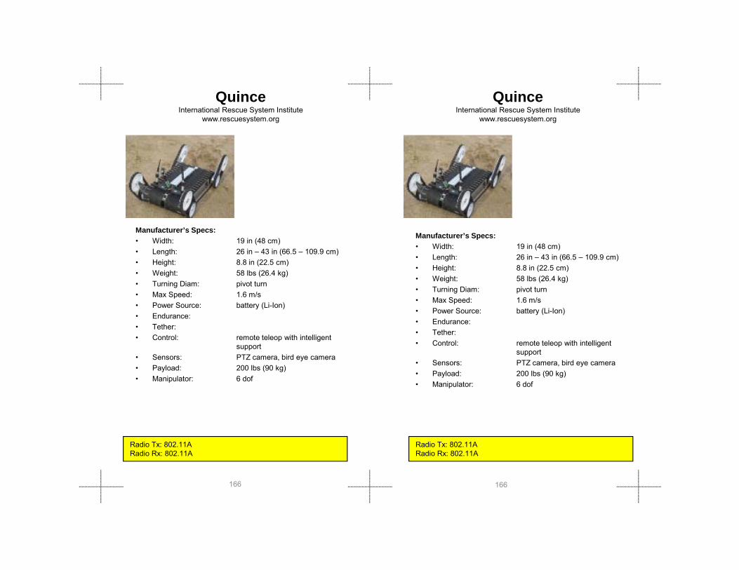
QuinceInternational Rescue System Institute
www.rescuesystem.org
Manufacturer’s Specs:• Width: 19 in (48 cm)• Length: 26 in – 43 in (66.5 – 109.9 cm)• Height: 8.8 in (22.5 cm)• Weight: 58 lbs (26.4 kg)• Turning Diam: pivot turn
QuinceInternational Rescue System Institute
www.rescuesystem.org
Manufacturer’s Specs:• Width: 19 in (48 cm)• Length: 26 in – 43 in (66.5 – 109.9 cm)• Height: 8.8 in (22.5 cm)• Weight: 58 lbs (26.4 kg)
166166
Turning Diam: pivot turn• Max Speed: 1.6 m/s• Power Source: battery (Li-Ion)• Endurance: • Tether:• Control: remote teleop with intelligent
support• Sensors: PTZ camera, bird eye camera• Payload: 200 lbs (90 kg)• Manipulator: 6 dof
Radio Tx: 802.11ARadio Rx: 802.11A
• Turning Diam: pivot turn• Max Speed: 1.6 m/s• Power Source: battery (Li-Ion)• Endurance: • Tether:• Control: remote teleop with intelligent
support• Sensors: PTZ camera, bird eye camera• Payload: 200 lbs (90 kg)• Manipulator: 6 dof
Radio Tx: 802.11ARadio Rx: 802.11A

Gro
und
Rob
ots
Gro
und
Rob
ots
Manufacturer’s Specs:• Width: 20.5 in (52.1 cm)• Length: 27 in (69 cm) • Height: 12.0 in (30.5 cm)• Weight: 58.8 lbs (26.7 kg)
• Chassis (including full flippers) 31.0 lbs (14.1 kg)• Camera Arm “CAM”: 5 8 lbs (2 6 kg)
PackBot with CAM, SAM and EAP Payloads
iRobotwww.irobot.com781-345-0200
Manufacturer’s Specs:• Width: 20.5 in (52.1 cm)• Length: 27 in (69 cm) • Height: 12.0 in (30.5 cm)• Weight: 58.8 lbs (26.7 kg)
• Chassis (including full flippers) 31.0 lbs (14.1 kg)• Camera Arm “CAM”: 5 8 lbs (2 6 kg)
PackBot with CAM, SAM and EAP Payloads
iRobotwww.irobot.com781-345-0200
167167
Camera Arm CAM : 5.8 lbs (2.6 kg)• Small Arm Manipulator “SAM”: 8.2 lbs (3.7 kg) • Enhanced Aware Payload “EAP”:2.5 lbs (1.1 kg) • COFDM Radio:5.0 lbs (2.3 kg)• Batteries (2 BB-2590s): 6.3 lbs (2.9 kg)
• Turning Dia: • Max Speed: • Power Source: battery• Endurance: Approximately 4 hours• Tether: Fiber-optic tether available• Control: Eyes-on, remote teleop, preset
poses• Sensors: LWIR Thermal Camera• Payload: • Manipulator: 4 DOF
Radio TX/RX:COFDM: 4400 – 4940 MHz / 100mWCommSelect: 4940 – 4990 MHz / 400 mWEmbedded Radio: 2412 – 2472 MHz / 630 mW

Manufacturer’s Specs:• Width: 21 in (53.34 cm)• Length: 30 in – 34 in (76.2cm- 86.36cm)• Height: 12 in (30.48 cm)• Weight: 61 lbs (27.66 kg)• Turning Dia: zero
MatildaMesa Robotics, Inc.
www.mesa-robotics.com256-258-2130/Don Jones
Manufacturer’s Specs:• Width: 21 in (53.34 cm)• Length: 30 in – 34 in (76.2cm- 86.36cm)• Height: 12 in (30.48 cm)• Weight: 61 lbs (27.66 kg)• Turning Dia: zero
MatildaMesa Robotics, Inc.
www.mesa-robotics.com256-258-2130/Don Jones
168168
Radio TX: 900 MHz control, 1800 MHz video, 469 MHz audioRadio RX: 900 MHz control, 1800 MHz video, 469 MHz audio
g• Max Speed: 2.0 mph• Power Source: 12VCD battery, NiMH• Endurance: 360 – 480 min• Tether: fiber optic cable (data,video, audio)• Control: remote teleop• Sensors: biological, chemical, radiological• Payload: 125 lbs• Manipulator: 5 DOF with 44 in reach (adds
45lbs/20.4kg to weight)

Gro
und
Rob
ots
Gro
und
Rob
ots
Manufacturer’s Specs:• Width: 21 in (53.34 cm)• Length: 30 in – 34 in (76.2cm- 86.36cm)• Height: 12 in (30.48 cm)• Weight: 61 lbs (27.66 kg)• Turning Dia: zero
Matilda IIMesa Robotics, Inc.
www.mesa-robotics.com256-258-2130/Don Jones
Manufacturer’s Specs:• Width: 21 in (53.34 cm)• Length: 30 in – 34 in (76.2cm- 86.36cm)• Height: 12 in (30.48 cm)• Weight: 61 lbs (27.66 kg)• Turning Dia: zero
Matilda IIMesa Robotics, Inc.
www.mesa-robotics.com256-258-2130/Don Jones
169169
Radio TX: 900 MHz control, 1800 MHz video, 469 MHz audioRadio RX: 900 MHz control, 1800 MHz video, 469 MHz audio
g• Max Speed: 2.0 mph• Power Source: 12VCD battery, NiMH• Endurance: 360 – 480 min• Tether: fiber optic cable (data,video, audio)• Control: remote teleop• Sensors: biological, chemical, radiological• Payload: 125 lbs• Manipulator: 5 DOF with 44 in reach (adds
45lbs/20.4kg to weight)

Manufacturer’s Specs:• Width: 20 1/2 in (52.1 cm)• Length: 27 in (68.6 cm)• Height: 16 in (40.6 cm)• Weight: 62.8 lbs (328.5 kg)
• Chassis (full flippers): 31.0 lbs (14.1 kg)• 3-Link Arm: 20 5 lbs (9 3 kg)
PackBot with EOD Payloads
iRobotwww.irobot.com781-345-0200
PackBot with EOD Payloads
iRobotwww.irobot.com781-345-0200
Manufacturer’s Specs:• Width: 20 1/2 in (52.1 cm)• Length: 27 in (68.6 cm)• Height: 16 in (40.6 cm)• Weight: 62.8 lbs (328.5 kg)
• Chassis (full flippers): 31.0 lbs (14.1 kg)• 3-Link Arm: 20.5 lbs (9.3 kg)
COFDM R di 5 0 lb (2 3 k )
170170
3 Link Arm: 20.5 lbs (9.3 kg)• COFDM Radio: 5.0 lbs (2.3 kg)• Batteries (2 BB-2590s): 6.3 lbs (2.9 kg)
• Turning Dia: 0 in (0 cm)• Max Speed: 8.5 fps (2.6 mps)• Power Source: BB-2590 Lithium-Ion batteries• Endurance: Approximately 4 hours• Tether: Fiber-optic tether available• Control: Eyes-on, remote teleop, preset
poses• Sensors: LWIR Thermal Camera• Payload: • Manipulator: 3 link arm DOF 8
Radio TX/RX:COFDM: 4400 – 4940 MHz / 100mWCommSelect: 4940 – 4990 MHz / 400 mWEmbedded Radio: 2412 – 2472 MHz / 630 mW
Radio TX/RX:COFDM: 4400 – 4940 MHz / 100mWCommSelect: 4940 – 4990 MHz / 400 mWEmbedded Radio: 2412 – 2472 MHz / 630 mW
• COFDM Radio: 5.0 lbs (2.3 kg)• Batteries (2 BB-2590s): 6.3 lbs (2.9 kg)
• Turning Dia: 0 in (0 cm)• Max Speed: 8.5 fps (2.6 mps)• Power Source: BB-2590 Lithium-Ion batteries• Endurance: Approximately 4 hours• Tether: Fiber-optic tether available• Control: Eyes-on, remote teleop, preset
poses• Sensors: LWIR Thermal Camera• Payload: • Manipulator: 3 link arm DOF 8

Gro
und
Rob
ots
Gro
und
Rob
ots
Packbot 510-EFRiRobot
www.irobot.com781-345-0200
Manufacturer’s Specs:• Width: 20 1/2 in (52.1 cm)• Length: 31 in (79 cm)• Height: 17 in (43 cm)• Weight: 69 lbs (31.3 kg)• Turning Dia: within the length of vehicle• Max Speed: 4 7 mph (7 5 km/hr)
Packbot 510-EFRiRobot
www.irobot.com781-345-0200
Manufacturer’s Specs:• Width: 20 1/2 in (52.1 cm)• Length: 31 in (79 cm)• Height: 17 in (43 cm)• Weight: 69 lbs (31.3 kg)• Turning Dia: within the length of vehicle• Max Speed: 4.7 mph (7.5 km/hr)
P S 2 Lithi I B tt
171171
Radio TX: 4900 MHz control, video, audio (0.4W)Radio RX: 4900 MHz control, video, audio (0.4W)
Max Speed: 4.7 mph (7.5 km/hr)• Power Source: 2 Lithium Ion Battery• Endurance: 216 min (3 hrs, 36 mins)• Tether: Not available• Control: RF Control• Sensors: 1 camera with low-light, 3 other
cameras• Payload: 30 lbs (13.6 kg) Arm compact
position 10 lbs (4.5 kg) Arm extended position
• Manipulator: Arm Reach up: 91 in (231 cm)
• Horizontal Reach: 87 in (221 cm)
Radio TX: 4900 MHz control, video, audio (0.4W)Radio RX: 4900 MHz control, video, audio (0.4W)
• Power Source: 2 Lithium Ion Battery• Endurance: 216 min (3 hrs, 36 mins)• Tether: Not available• Control: RF Control• Sensors: 1 camera with low-light, 3 other
cameras• Payload: 30 lbs (13.6 kg) Arm compact
position 10 lbs (4.5 kg) Arm extended position
• Manipulator: Arm Reach up: 91 in (231 cm)
• Horizontal Reach: 87 in (221 cm)

NuTech-R4Nagaoka Univ. of Tech. / Nagaoka TEKKO-SEIKEN (Joint Team)
http://sessyu.nagaokaut.ac.jp/~kimuralab/Tetsuya KIMURA, [email protected]
Manufacturer’s Specs:• Width: 16.93 in (43 cm)• Length: 24.41 (62 cm) 35.43 (90 cm with
flipper extension)• Height: 17.72 in (45 cm)• Weight: 77 lbs (35 kg)• Steering: skid
NuTech-R4Nagaoka Univ. of Tech. / Nagaoka TEKKO-SEIKEN (Joint Team)
http://sessyu.nagaokaut.ac.jp/~kimuralab/Tetsuya KIMURA, [email protected]
Manufacturer’s Specs:• Width: 16.93 in (43 cm)• Length: 24.41 (62 cm) 35.43 (90 cm
with flipper extension)• Height: 17.72 in (45 cm)• Weight: 77 lbs (35 kg)• Steering: skid
172172
Radio TX: 802.11 a /g/nRadio RX: 802.11 a /g/n
Radio TX: 802.11 a /g/nRadio RX: 802.11 a /g/n
g• Turning Diam: 29.53 (75 cm)• Max Speed: 0.3 mps • Power Source: battery • Endurance: 30 min• Tether: communication (optional)• Control: remote tele-operation• Sensors: thermal, sound, arm camera• Payload: 3 kg (body), 300 g (manipulator)• Manipulator: 5 DOFs, reach 39.37 in (100 cm)
Steering: skid• Turning Diam: 29.53 (75 cm)• Max Speed: 0.3 mps • Power Source: battery • Endurance: 30 min• Tether: communication (optional)• Control: remote tele-operation• Sensors: thermal, sound, arm camera• Payload: 3 kg (body), 300 g (manipulator)• Manipulator: 5 DOFs, reach 39.37 in (100 cm)

Gro
und
Rob
ots
Gro
und
Rob
ots
Manufacturer’s Specs:• Width: 20 in (49 cm)• Length: 22.44 in (57 cm)• Height: 7.8 in – 48 in (20 cm - 122 cm)• Weight: 88 lbs (40 kg)• Turning Diam:• Max Speed: 7 km/p
Helios IXInternational Rescue System Institute
www.rescuesystem.org
Manufacturer’s Specs:• Width: 20 in (49 cm)• Length: 22.44 in (57 cm)• Height: 7.8 in – 48 in (20 cm - 122 cm)• Weight: 88 lbs (40 kg)• Turning Diam:• Max Speed: 7 km/p
Helios IXInternational Rescue System Institute
www.rescuesystem.org
173173
Max Speed: 7 km/p• Power Source: battery • Endurance: • Tether:• Control: remote teleop• Sensors: Camera, 2-D laser range finder,
attitude • Payload: unknown• Manipulator: 6DOFs
Radio Tx: 802.11 a,b,g,nRadio Rx: 802.11 a,b,g,n
Max Speed: 7 km/p• Power Source: battery • Endurance: • Tether:• Control: remote teleop• Sensors: Camera, 2-D laser range finder,
attitude • Payload: unknown• Manipulator: 6DOFs
Radio Tx: 802.11 a,b,g,nRadio Rx: 802.11 a,b,g,n

Manufacturer’s Specs:• Width: 17 in (43 cm)• Length: 86 in (34 cm)• Height: 29.5 (75 cm)• Weight: 88 lbs (40 kg)• Turning Diam:• Max Speed: 3 0 m/s
KOHGA International Rescue System Institute
www.rescuesystem.org
Manufacturer’s Specs:• Width: 17 in (43 cm)• Length: 86 in (34 cm)• Height: 29.5 (75 cm)• Weight: 88 lbs (40 kg)• Turning Diam:• Max Speed: 3 0 m/s
KOHGA International Rescue System Institute
www.rescuesystem.org
174174
Max Speed: 3.0 m/s• Power Source: battery • Endurance: 60 min• Tether: none• Control: remote teleop• Sensors: thermal, Co2,mic, Camera, URG-
04LX,AMU• Payload: unknown• Manipulator: 6DOFs
Radio Tx: 5200 MhZ (10mW)Radio Rx: 5200 MhZ (10mW)
Radio Tx: 5200 MhZ (10mW)Radio Rx: 5200 MhZ (10mW)
Max Speed: 3.0 m/s• Power Source: battery • Endurance: 60 min• Tether: none• Control: remote teleop• Sensors: thermal, Co2,mic, Camera, URG-
04LX,AMU• Payload: unknown• Manipulator: 6DOFs

Gro
und
Rob
ots
Gro
und
Rob
ots
Versatrax 150SeaTrepid
www.inuktun.comBob Christ
Manufacturer’s Specs:• Width: Inline: 4.5 in (11.43 cm)• Parallel: 11.5 in (29.21cm) and larger• Length: Inline: 64 in (162.5 cm)• Parallel: 24 in (61cm)• Height: Inline: 8.57 in (21.8 cm) and larger• Weight: 88 lbs (40 kg)
Versatrax 150SeaTrepid
www.inuktun.comBob Christ
Manufacturer’s Specs:• Width: Inline: 4.5 in (11.43 cm)• Parallel: 11.5 in (29.21cm) and larger• Length: Inline: 64 in (162.5 cm)• Parallel: 24 in (61cm)• Height: Inline: 8.57 in (21.8 cm) and larger• Weight: 88 lbs (40 kg)
175175
• Steering: Skid steering• Turning Diam: Various; depending on pipe diameters• Max Speed: 30 fpm (9 mpm) • Power Source: 88-264 VAC 50/60Hz • Endurance: Continuous• Tether: Power and comms• Control: Remote teleop• Sensors: Sonar, sonde• Payload: N/A• Manipulator: N/A
Radio TX:Radio RX:
Weight: 88 lbs (40 kg)• Steering: Skid steering• Turning Diam: Various; depending on pipe diameters• Max Speed: 30 fpm (9 mpm) • Power Source: 88-264 VAC 50/60Hz • Endurance: Continuous• Tether: Power and comms• Control: Remote teleop• Sensors: Sonar, sonde• Payload: N/A• Manipulator: N/A
Radio TX: Radio RX:

Talon Gen IVQinetiq North America / Foster-Miller Inc.
www.foster-miller.com/lemming.htm781-684-4000
Talon Gen IVQinetiq North America / Foster-Miller Inc.
www.foster-miller.com/lemming.htm781-684-4000
Manufacturer’s Specs:• Width: 22 in (56.88 cm)• Length: 34 in (86.36 cm)• Height: 11 in-52 in (27.9 c m - 132 cm)• Weight: 115 to 140 lb (52kg to 64 kg)• Turning Dia: turns in place• Max Speed: 0 to 5.2 mph (0-8.3 km/hr
P S Si l Lithi i B tt D l
Manufacturer’s Specs:• Width: 22 in (56.88 cm)• Length: 34 in (86.36 cm)• Height: 11 in-52 in (27.9 c m-132 cm)• Weight: 115 to 140 lb (52kg to 64 kg)• Turning Dia: turns in place• Max Speed: 0 to 5.2 mph (0-8.3 km/hr
P S Si l Lithi i B tt D l
176176
Radio TX: Data 2400MHz / Video 1700-1800MHz Radio RX: Data 2400MHz / Video 1700-1800MHz
• Power Source: Single Lithium-ion Battery or Dual Lead-Acid Battery Pack
• Endurance: 4.5 hr (7.2 km/hr)• Tether: Optional 300 or 500 m buffered fiber
optic cable• Control: digital/analog, 500-800 m LOS
High Gain antenna range to 1200m LOS
• Sensors: Chemsentry 150 C, ADP 2000, RAE System MultiRAE, Canberra AN-UDR-14, RayTek temp. probe, targeting laser
• Payload: 100 lb (45 kg)• Manipulator: 30 in-lb of gripping strength, 6 in
wide opening, manual 340 degree wrist
Radio TX: Data 2400MHz / Video 1700-1800MHz Radio RX: Data 2400MHz / Video 1700-1800MHz
• Power Source: Single Lithium-ion Battery or Dual Lead-Acid Battery Pack
• Endurance: 4.5 hr (7.2 km/hr)• Tether: Optional 300 or 500 m buffered
fiber optic cable• Control: digital/analog, 500-800 m LOS
High Gain antenna range to 1200m LOS
• Sensors: Chemsentry 150 C, ADP 2000, RAE System MultiRAE, Canberra AN-
UDR-14, RayTek temp. probe, targeting laser
• Payload: 100 lb (45 kg)• Manipulator: 30 in-lb of gripping strength, 6 in
wide opening, manual 340 degree wrist

Gro
und
Rob
ots
Gro
und
Rob
ots
Talon Gen IV -HazmatQinetiq North America / Foster-Miller Inc.
www.foster-miller.com/lemming.htm781-684-4000
Manufacturer’s Specs:• Width: 22.5 in (57.2 cm)• Length: 34 in (86.4 cm)• Height: 11 in (27.9 cm)• Weight: 115 to 140 lb (52kg to 64 kg)• Turning Dia: On axis• Max Speed: 7 6 fps (1 8mps)
Talon Gen IV -HazmatQinetiq North America / Foster-Miller Inc.
www.foster-miller.com/lemming.htm781-684-4000
Manufacturer’s Specs:• Width: 22.5 in (57.2 cm)• Length: 34 in (86.4 cm)• Height: 11 in (27.9 cm)• Weight: 115 to 140 lb (52kg to 64 kg)• Turning Dia: On axis• Max Speed: 7 6 fps (1 8mps)
177177
Max Speed: 7.6 fps (1.8mps)• Power Source: Battery Pack • Endurance: 4.5 hr (7.2 km/hr)• Tether: Fiber Optics (option)• Control: remote teleop• Sensors: chemical warfare agents (blood,
nerve, blister), TIC, radiation Payload: 100 lb (45 kg)
• Manipulator: reach 52 in (1.3 m)
Radio TX: 1650-1900 MHz / 2000 mW (video), 148-174 MHz/ 600 mW (audio), 2.3-2.4 MHz / 5-500 mW (commands)

Talon Gen IV -ShoulderQinetiq North America / Foster-Miller Inc.
www.foster-miller.com/lemming.htm781-684-4000
Talon Gen IV -ShoulderQinetiq North America / Foster-Miller Inc.
www.foster-miller.com/lemming.htm781-684-4000
178178
Radio TX: 1650-1900 MHz / 2000 mW (video), 148-174 MHz/ 600 mW (audio), 2.3-2.4 MHz / 5-500 mW (commands)
Radio TX: 1650-1900 MHz / 2000 mW (video), 148-174 MHz/ 600 mW (audio), 2.3-2.4 MHz / 5-500 mW (commands)

Gro
und
Rob
ots
Gro
und
Rob
ots
ChaosAutonomous Solutions.
www.autonomoussolutions.comOmar Salas
Manufacturer’s Specs:• Width: 28 in (70 cm)• Length: 28 in (71 cm)• Height: 8 in (20 cm)• Weight: 120 lbs (55 kg)• Turning Dia: 39 in ( 100)
M S d TBD
ChaosAutonomous Solutions.
www.autonomoussolutions.comOmar Salas
Manufacturer’s Specs:• Width: 28 in (70 cm)• Length: 28 in (71 cm)• Height: 8 in (20 cm)• Weight: 120 lbs (55 kg)• Turning Dia: 39 in ( 100)
179179
Radio TX: 2400 MHz/1000 mW (Video) 900 MHZ/1000 mW (data)Radio RX: 2400 MHz/1000 mW (Video) 900 MHZ/1000 mW (data)
• Max Speed: TBD• Power Source: Lithium battery • Endurance: 240 min• Tether: None• Control: remote teleop• Sensors: 2 Cams• Payload: TBD• Manipulator: None
Radio TX: 2400 MHz/1000 mW (Video) 900 MHZ/1000 mW (data)Radio RX: 2400 MHz/1000 mW (Video) 900 MHZ/1000 mW (data)
g ( )• Max Speed: TBD• Power Source: Lithium battery • Endurance: 240 min• Tether: None• Control: remote teleop• Sensors: 2 Cams• Payload: TBD• Manipulator: None

Manufacturer’s Specs:• Width: 33 in (84 cm)• Length: 26.5 in (67 cm)• Height: xxx in (xxx cm)• Weight: 120 lbs (55 kg)• Turning Dia: 42 in (107 cm)• Max Speed: 12.5 mph (20 km/h) Power Source:
Modular Logistics PlatformSegway, Inc.
www.segway.com603-222-6000
Modular Logistics PlatformSegway, Inc.
www.segway.com603-222-6000
Manufacturer’s Specs:• Width: 33 in (84 cm)• Length: 26.5 in (67 cm)• Height: xxx in (xxx cm)• Weight: 120 lbs (55 kg)• Turning Dia: 42 in (107 cm)
180180
Radio TX: 2400 MHz/XXXmW (Video) 2400 MHZ/xxx mW (data)
p p ( )Two lithium-ion battery packs
• Endurance: 12 miles (19 km) off pavement• Tether: None• Control: dynamically stabilized, ride
onboard, remote teleoperative or autonomous
• Sensors: gyros, wheel encoders, camera
• Payload: 260 lb (118 kg) • Manipulator: None
Radio TX: 2400 MHz/XXXmW (Video) 2400 MHZ/xxx mW (data)
• Max Speed: 12.5 mph (20 km/h) Power Source: Two lithium-ion battery packs
• Endurance: 12 miles (19 km) off pavement• Tether: None• Control: dynamically stabilized, ride
onboard, remote teleoperative or autonomous
• Sensors: gyros, wheel encoders, camera
• Payload: 260 lb (118 kg) • Manipulator: None

Gro
und
Rob
ots
Gro
und
Rob
ots
ATRV miniIdaho National Lab
www.inl.gov/adaptiverobotics208-526-8659 /Curtis Nielsen
Manufacturer’s Specs:• Width: 22 in (55.8 cm)• Length: 27 in (68.6 cm)• Height: 25 in (63.5 cm)• Weight: 125 lbs (56.7 kg)• Turning Diam: 0 (turns on center off robot)• Max Speed: 6 5 fps (2 mps)
ATRV miniIdaho National Lab
www.inl.gov/adaptiverobotics208-526-8659 /Curtis Nielsen
Manufacturer’s Specs:• Width: 22 in (55.8 cm)• Length: 27 in (68.6 cm)• Height: 25 in (63.5 cm)• Weight: 125 lbs (56.7 kg)• Turning Diam: 0 (turns on center off robot)• Max Speed: 6 5 fps (2 mps)
181181
Radio TX: 900 MHz (500 mW), 2400 MHz (500 mW)Radio RX: 900 MHz (500 mW), 2400 MHz
Max Speed: 6.5 fps (2 mps) • Power Source: battery • Endurance: 30-45 min• Tether: none• Control: eyes-on, remote teleop, waypoints,
go to landmarks, drive intent• Sensors: color video, laser range scanner,
ultrasonic sonar sensor.• Payload: 35 lb (15.9 kg)• Manipulator: none
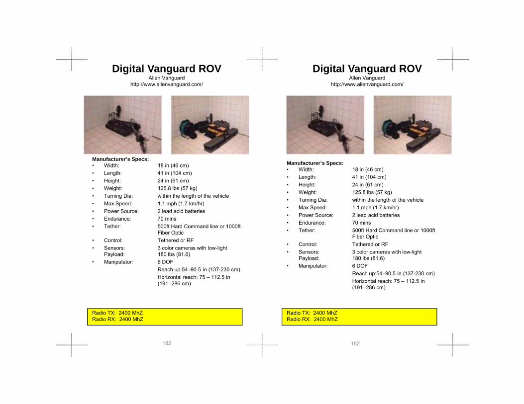
Digital Vanguard ROVAllen Vanguard
http://www.allenvanguard.com/
Digital Vanguard ROVAllen Vanguard
http://www.allenvanguard.com/
Manufacturer’s Specs:• Width: 18 in (46 cm)• Length: 41 in (104 cm)• Height: 24 in (61 cm)• Weight: 125.8 lbs (57 kg)• Turning Dia: within the length of the vehicle
M S d 1 1 h (1 7 k /h )
Manufacturer’s Specs:• Width: 18 in (46 cm)• Length: 41 in (104 cm)• Height: 24 in (61 cm)• Weight: 125.8 lbs (57 kg)• Turning Dia: within the length of the vehicle
182182
Radio TX: 2400 MhZ Radio RX: 2400 MhZ
Radio TX: 2400 MhZ Radio RX: 2400 MhZ
• Max Speed: 1.1 mph (1.7 km/hr)• Power Source: 2 lead acid batteries• Endurance: 70 mins• Tether: 500ft Hard Command line or 1000ft
Fiber Optic• Control: Tethered or RF• Sensors: 3 color cameras with low-light
Payload: 180 lbs (81.6)• Manipulator: 6 DOF
Reach up:54–90.5 in (137-230 cm)Horizontal reach: 75 – 112.5 in (191 -286 cm)
g g• Max Speed: 1.1 mph (1.7 km/hr)• Power Source: 2 lead acid batteries• Endurance: 70 mins• Tether: 500ft Hard Command line or 1000ft
Fiber Optic• Control: Tethered or RF• Sensors: 3 color cameras with low-light
Payload: 180 lbs (81.6)• Manipulator: 6 DOF
Reach up:54–90.5 in (137-230 cm)Horizontal reach: 75 – 112.5 in (191 -286 cm)

Gro
und
Rob
ots
Gro
und
Rob
ots
Manufacturer’s Specs:• Width: 29.5 in (75 cm)• Length: 25 in 64 cm)• Height: 24 in (61 cm)• Weight: 140 lbs (64 kg)• Turning Dia: 39 in (99 cm)• Max Speed: 10 mph (16 km/h)
P S T lithi i b tt k
Robotic Mobility Platform(RMP 200/INL)
Segway, Inc.www.segway.com/603-222-6000
Robotic Mobility Platform(RMP 200/INL)
Segway, Inc.www.segway.com/603-222-6000
Manufacturer’s Specs:• Width: 29.5 in (75 cm)• Length: 25 in 64 cm)• Height: 24 in (61 cm)• Weight: 140 lbs (64 kg)• Turning Dia: 39 in (99 cm)• Max Speed: 10 mph (16 km/h)
183183
Radio TX: 2400 MHz/XXXmW (Video) 900 MHZ/xxx mW (data)
• Power Source: Two lithium-ion battery packs• Endurance: 15 miles (24 km)• Tether: None• Control: dynamically stabilized,
remote teleoperative or autonomous
• Sensors: gyros, wheel encoders, camera, laser scanner for mapping
• Payload: 200 lb (91 kg)• Manipulator: Barrett Technology WAM
Radio TX: 2400 MHz/XXXmW (Video) 900 MHZ/xxx mW (data)
Max Speed: 10 mph (16 km/h) • Power Source: Two lithium-ion battery packs• Endurance: 15 miles (24 km)• Tether: None• Control: dynamically stabilized,
remote teleoperative or autonomous
• Sensors: gyros, wheel encoders, camera, laser scanner for mapping
• Payload: 200 lb (91 kg)• Manipulator: Barrett Technology WAM

teleMAXtelerob GmbHwww.telerob.de
Manufacturer’s Specs:• Width: 15.75 in (40 cm)• Length: 31.5 in - 63 in (80 cm – 160 cm)• Height: 29.53 in ( 75 cm) (stowed)• Weight: 175 lbs (79.4 kg)• Turning Dia: 39.37 in (100cm)• Max Speed: tracks 2 16 mph (3 5 kmh)
Manufacturer’s Specs:• Width: 15.75 in (40 cm)• Length: 31.5 in - 63 in (80 cm – 160 cm)• Height: 29.53 in ( 75 cm) (stowed)• Weight: 175 lbs (79.4 kg)• Turning Dia: 39.37 in (100cm)• Max Speed: tracks 2 16 mph (3 5 kmh)
teleMAXtelerob GmbHwww.telerob.de
184184
Max Speed: tracks 2.16 mph (3.5 kmh), wheels 2.92 mph (4.7 kmh) Power
Source: NiMh, 24V DC• Endurance: 2 hours• Tether: none, fiber with video and
comms• Control: eyes-on, remote teleop• Sensors: optional chemical, radiation,
gas, GPS • Payload: 22 lbs (10kg)• Manipulator: 7 DOFs, reach 92,52 in to
102,36 in (235 cm to 260 cm)
Radio TX: Data 433-435MHz/500mW, Video 2300 MHz/3WRadio RX:
TEST DATA IS AVAILABLE TEST DATA IS AVAILABLE

Gro
und
Rob
ots
Gro
und
Rob
ots
Manufacturer’s Specs:• Width: 24 1/2 in (62 cm)• Length: 43 1/2 in (111 cm)• Height: 31 in (79 cm)• Weight: 199 lbs (90.3 kg)• Turning Dia: within the length of vehicle• Max Speed: 2.9 mph (4.6 km/hr)
P S 1 L d A id B tt
Caliber MK3 EODICOR Technology
www.icortechnology.com613-745-3600
Manufacturer’s Specs:• Width: 24 1/2 in (62 cm)• Length: 43 1/2 in (111 cm)• Height: 31 in (79 cm)• Weight: 199 lbs (90.3 kg)• Turning Dia: within the length of vehicle• Max Speed: 2.9 mph (4.6 km/hr)
P S 1 L d A id B tt
Caliber MK3 EODICOR Technology
www.icortechnology.com613-745-3600
185185
• Power Source: 1 Lead Acid Battery• Endurance: 58 mins,1260 meters (as tested)• Tether: Standard 300ft (92m) Tether; used
as an alternative to RF control• Control: Tether or RF• Sensors: 6 cameras with low-light• Payload: 65 lbs (29.5 kg)• Manipulator: Arm Reach up: 71 1/2 in (182
cm) Horizontal Reach: 71 in (180 cm)
Radio TX RX: Control 900 Mhz/Video 2.4Mhz/Audio 465Mhz

Andros HD-1JREMOTEC, Inc.
www.remotec-andros.com 865-483-0228/Jim Daniels
Manufacturer’s Specs:• Width: 26 in (66 cm)• Length: 47.5 in (120.65 cm)• Height: 30 in (76cm) antenna 70 in(177.8)• Weight: 200 lbs (90.72 kg)• Turning Dia: • Max Speed: 4 3mph
Andros HD-1JREMOTEC, Inc.
www.remotec-andros.com 865-483-0228/Jim Daniels
Manufacturer’s Specs:• Width: 26 in (66 cm)• Length: 47.5 in (120.65 cm)• Height: 30 in (76cm) wantenna 70
in(177.8)• Weight: 200 lbs (90.72 kg)• Turning Dia:
186186
Radio TX RX: Control 464.5 Mhz/Video 2.4Mhz/Audio 151.9Mhz
Max Speed: 4.3mph• Power Source: Lithium Polymer Battery• Endurance: 3-6 hr • Tether: Fiber-Optic Cable • Control: tethered/Radio Control• Sensors: Color Camera/LED lighting/• Payload: TBD• Manipulator: 72 in (182.88 cm)Max. Gripper
Height 6 in (15.2 cm) Gripper with 360 degree rotation, weapons with gripper capable
Radio TX RX: Control 464.5 Mhz/Video 2.4Mhz/Audio 151.9Mhz
g• Max Speed: 4.3mph• Power Source: Lithium Polymer Battery• Endurance: 3-6 hr • Tether: Fiber-Optic Cable • Control: tethered/Radio Control• Sensors: Color Camera/LED lighting/• Payload: TBD• Manipulator: 72 in (182.88 cm)Max. Gripper
Height 6 in (15.2 cm) Gripper with 360 degree rotation, weapons with gripper capable

Gro
und
Rob
ots
Gro
und
Rob
ots
Mini-Andros IIREMOTEC, Inc.
www.remotec-andros.com 865-483-0228/Jim Daniels
Manufacturer’s Specs:• Width: 24.5 in (62 cm)• Length: 53 in (134 cm) • Height: 27 in (68 cm)• Weight: 225 lbs (102.6 kg)• Turning Dia: length of vehicle• Max Speed: 1.1 mph(1.7 km/hr)
P S 24VDC l ll b tt k
Mini-Andros IIREMOTEC, Inc.
www.remotec-andros.com 865-483-0228/Jim Daniels
Manufacturer’s Specs:• Width: 24.5 in (62 cm)• Length: 53 in (134c m) • Height: 27 in (68 cm)• Weight: 225 lbs (102.6 kg)• Turning Dia: length of vehicle• Max Speed: 1 1 mph(1 7 km/hr)
187187
Radio TX: tethered or RFRadio RX: tethered or RF
• Power Source: 24VDC - gel cell battery packBattery
• Endurance: 3-6 hr • Tether: Fiber-Optic Cable or hard tether
cable • Control: tethered,Radio Control• Sensors: Color Camera • Payload: 15 lbs (6.8 kg)• Manipulator: 78 in (2 m) telescoping arm with
four degrees of freedom
Radio TX: tethered or RFRadio RX: tethered or RF
Max Speed: 1.1 mph(1.7 km/hr)• Power Source: 24VDC - gel cell battery pack
Battery• Endurance: 3-6 hr • Tether: Fiber-Optic Cable or hard tether
cable • Control: tethered,Radio Control• Sensors: Color Camera • Payload: 15 lbs (6.8 kg)• Manipulator: 78 in (2 m) telescoping arm with
four degrees of freedom

Manufacturer’s Specs:• Width: 30 in (76 cm)• Length: 44 in (112 cm)• Height: 24 in (61 cm)• Weight: 240 lbs (109 kg)• Turning Dia: 53 in (135 cm)• Max Speed: 18 mph (29 km/h)
P S F lithi i b tt k
Robotic Mobility Platform(RMP 400/INL)
Segway, Inc.www.segway.com/Will Pong/603-222-6000
Manufacturer’s Specs:• Width: 30 in (76 cm)• Length: 44 in (112 cm)• Height: 24 in (61 cm)• Weight: 240 lbs (109 kg)• Turning Dia: 53 in (135 cm)• Max Speed: 18 mph (29 km/h)
Robotic Mobility Platform(RMP 400/INL)
Segway, Inc.www.segway.com/Will Pong/603-222-6000
188188
Radio TX: 75 MHz/XXXmW (Video) 2400 MHZ/xxx mW (data)
• Power Source: Four lithium-ion battery packs• Endurance: 15 miles (24 km)• Tether: None• Control: Statically stabilized,
remote teleoperative or autonomous
• Sensors: gyros, wheel encoders, • Payload: 400 lb (180 kg)• Manipulator: Barrett Technology WAM
Radio TX: 75 MHz/XXXmW (Video) 2400 MHZ/xxx mW (data)
Max Speed: 18 mph (29 km/h) • Power Source: Four lithium-ion battery packs• Endurance: 15 miles (24 km)• Tether: None• Control: Statically stabilized,
remote teleoperative or autonomous
• Sensors: gyros, wheel encoders, • Payload: 400 lb (180 kg)• Manipulator: Barrett Technology WAM

Gro
und
Rob
ots
Gro
und
Rob
ots
Andros F6AREMOTEC, Inc.
www.remotec-andros.com 865-483-0228/Jim Daniels
Manufacturer’s Specs:• Width: 29 in (73 cm • Length: 52 in (132 cm) • Height: 56.5 in (140 cm)• Weight: 485 lb (219.99kg) • Turning Dia: within the length of vehicle• Max Speed: 3 5 mph (5 6 km/hr)
Andros F6AREMOTEC, Inc.
www.remotec-andros.com 865-483-0228/Jim Daniels
Manufacturer’s Specs:• Width: 29 in (73 cm • Length: 52 in (132 cm) • Height: 56.5 in (140 cm)• Weight: 485 lb (219.99kg) • Turning Dia: within the length of vehicle• Max Speed: 3 5 mph (5 6 km/hr)
189189
Radio TX: tethered or RFRadio RX: tethered or RF
Max Speed: 3.5 mph (5.6 km/hr)• Power Source: 24VDC 35 amp-hr gel-cell battery
pack • Endurance: 3-6 hr• Tether: Interchangeable Fiber Optic Cable
reel, RF system, or Hard-line cable reel system
• Control: tethered or RF• Sensors: Color camera with low-light • Payload: 45 lbs (20.4 kg)• Manipulator: Arm -Vertical reach 109 in (2.76 m)
with tracks down and arm fully extended, Horizontal reach 56 in (1.42 m) from front of vehicle

CentaurThe MITRE Corporation
Manufacturer’s Specs:• Width: 118 in (300 cm)• Length: 72 in (183 cm)• Height: 74 in (188 cm)• Weight: 2420 lbs (1097 kg)
CentaurThe MITRE Corporation
Manufacturer’s Specs:• Width: 118 in (300 cm)• Length: 72 in (183 cm)• Height: 74 in (188 cm)• Weight: 2420 lbs (1097 kg)
190190
Radio TX: tethered or RFRadio RX: tethered or RF
g ( g)• Turning Dia: 0in (0 cm)• Max Speed: 28 mph, 41 fps (12.5 mps) • Power Source: 34 hp turbo Diesel • Endurance: 12 hours, 720 min• Tether: none• Control: remote teleop or waypoint with
obstacle avoidance• Sensors: Velodyne LIDAR, 2 SICK LMS,
Omni-directional color camera, GPS, INS
• Payload: 1500 lb (680 kg)• Manipulator: none, 4’ x 4’ bed for mounting

Gro
und
Rob
ots
Gro
und
Rob
ots
BOZ IBOZ Robotics
www.bozrobot.com 847-574-0168/Jamie Alvarez
Manufacturer’s Specs:• Width: 26.4 in ( 67 cm)• Length: 67.3 in (171 cm)• Height: 53.2 in (135 cm)• Weight: 1,300 lbs (600 kg)• Turning Dia: 360 degrees• Max Speed: 6 7 km/h
BOZ IBOZ Robotics
www.bozrobot.com 847-574-0168/Jamie Alvarez
Manufacturer’s Specs:• Width: 26.4 in ( 67 cm)• Length: 67.3 in (171 cm)• Height: 53.2 in (135 cm)• Weight: 1,300 lbs (600 kg)• Turning Dia: 360 degrees• Max Speed: 6 7 km/h
191191
Max Speed: 6.7 km/h • Power Source: battery• Endurance: 3 - 4 hrs to continuous
w/generator• Tether: 100 meter; 1 km remote los• Control: computer w/case and joystick• Sensors: ultra sound distance sensors (to
the cm) 5 cameras; 3 infrared• Payload: 265 lb (120 kg) lifting capacity
w/arm straight; 441 lbs (200 kg) arm bent• Manipulator: Hydraulic gripper w/12,717 lbs
(5,770 kg) of opening force, reach 11.5 ft (350 cm) and four joints independently operated to tear off car doors, trunks, & dexterity to pour a soda bottle in a glass
Radio TX: 2400 MHzRadio RX: 2400 MHz

192192

all
bers
all
bers
Wall Climbers Wall Climbers
Wa
Clim
b
Wa
Clim
b
193193

VMRPVortex HC LLC.
www.vortexhc.com919-462-8828
Manufacturer’s Specs:• Width: 8.5 in (21.5 cm) • Length: 6.5 in (16.5 cm) • Height: 4 in (10 cm)• Weight: 1.87 lbs (.84kg)• Turning Dia: TBD• Max Speed: 6 in/sec ( 154m/sec)
VMRPVortex HC LLC.
www.vortexhc.com919-462-8828
Manufacturer’s Specs:• Width: 8.5 in (21.5 cm) • Length: 6.5 in (16.5 cm) • Height: 4 in (10 cm)• Weight: 1.87 lbs (.84kg)• Turning Dia: TBD• Max Speed: 6 in/sec ( 154m/sec)
194194
Max Speed: 6 in/sec. (.154m/sec) • Power Source: battery• Endurance: 20- 40 minutes • Tether: none• Control: teleoped• Sensors: 2 color camera ( boom pan drive
camera)• Payload: 1 lbs (.45kg) (scalable)• Manipulator: n/a
Radio TX: 2400 MHz (Bluetooth) video 1200 MHzRadio RX: 2400 MHz (Bluetooth)
Max Speed: 6 in/sec. (.154m/sec) • Power Source: battery• Endurance: 20- 40 minutes • Tether: none• Control: teleoped• Sensors: 2 color camera ( boom pan drive
camera)• Payload: 1 lbs (.45kg) (scalable)• Manipulator: n/a
Radio TX: 2400 MHz (Bluetooth) video 1200 MHzRadio RX: 2400 MHz (Bluetooth)

all
bers
all
bers
NanoMagInuktun
www.inuktun.com/1-877-468-5886
Manufacturer’s Specs:• Width: 17 in (43.1cm )• Length: 12 in (30.4 cm)• Height: 3.5 in (8.8 cm) • Weight: 5 lbs (2.26kg) • Turning Dia: TBD• Max Speed: 0-5 ft/min (0-1 5 m/min)
NanoMagInuktun
www.inuktun.com/1-877-468-5886
Manufacturer’s Specs:• Width: 17 in (43.1cm )• Length: 12 in (30.4 cm)• Height: 3.5 in (8.8 cm) • Weight: 5 lbs (2.26kg) • Turning Dia: TBD• Max Speed: 0-5 ft/min (0-1 5 m/min)
Wa
Clim
b
Wa
Clim
b
195195
Max Speed: 0 5 ft/min (0 1.5 m/min)• Power Source: TBD• Endurance: TBD• Tether: 100ft (30m) • Control: teleoped • Sensors: TBD• Payload: TBD• Manipulator: n/a
Radio Tx: (tether only)Radio Rx: (tether only)
Max Speed: 0 5 ft/min (0 1.5 m/min)• Power Source: TBD• Endurance: TBD• Tether: 100ft (30m) • Control: teleoped • Sensors: TBD• Payload: TBD• Manipulator: n/a
Radio Tx: (tether only)Radio Rx: (tether only)

196196

Aerial Robots Aerial Robots
Aer
ial
Rob
ots
197197
Aer
ial
Rob
ots

NighthawkApplied Research Associates, Inc
www.ara.comAdam Sloan/[email protected]
Manufacturer's Specs:
• Wingspan: 2.2 ft (0.66 m) • Length: 1.7 ft (0.51 m)• Weight: 1.65 lbs (0.750 kg)• Range: 6.2 miles (10 km)• Speed: 28 mph (44 kmph)
NighthawkApplied Research Associates, Inc
www.ara.comAdam Sloan/[email protected]
Manufacturer's Specs:
• Wingspan: 2.2 ft (0.66 m) • Length: 1.7 ft (0.51 m)• Weight: 1.65 lbs (0.750 kg)• Range: 6.2 miles (10 km)• Speed: 28 mph (44 kmph)
198198
p p ( p )• Launch: hand• Recovery: skid land• Propulsion: electric motor • Altitude: 100-500 ft (30.48m-
152.4m) AGL• Endurance: 60-90 min• Control: auto waypoint following• Payload: color camera, infrared
Radio TX:915-928 MHz / 650 mW/2409-2469 MHz / 600 mWRadio RX:
p p ( p )• Launch: hand• Recovery: skid land• Propulsion: electric motor • Altitude: 100-500 ft (30.48m-
152.4m) AGL• Endurance: 60-90 min• Control: auto waypoint following• Payload: color camera, infrared
Radio TX:915-928 MHz / 650 mW/2409-2469 MHz / 600 mWRadio RX:

RavenAeroVironment Inc. www.avsuav.com
626-357-9983
Manufacturer's Specs:
• Wingspan: 4.5 ft (1.4 m)• Length: 3 ft (0.9 m)• Weight: 4.2 lbs (1.9 kg)• Range: 6.2 miles (10 km)• Speed: 20-50 mph ( 32-82 km/hr)
RavenAeroVironment Inc. www.avsuav.com
626-357-9983
Manufacturer's Specs:
• Wingspan: 4.5 ft (1.4 m)• Length: 3 ft (0.9 m)• Weight: 4.2 lbs (1.9 kg)• Range: 6.2 miles (10 km)• Speed: 20-50 mph ( 32-82 km/hr)
Aer
ial
Rob
ots
199199
Aer
ial
Rob
ots
p p ( )• Launch: hand• Recovery: deep stall vertical
Propulsion: electric motor • Altitude: 100-500 ft (30.48m-
152.4m) AGL• Endurance: 80-110 min• Control: auto waypoint following• Payload: color camera, infrared
Radio TX: Radio RX:
p p ( )• Launch: hand• Recovery: deep stall vertical
Propulsion: electric motor • Altitude: 100-500 ft (30.48m-
152.4m) AGL• Endurance: 80-110 min• Control: auto waypoint following• Payload: color camera, infrared
Radio TX: Radio RX:

Dragon EyeAeroVironment Inc. www.avsuav.com
626-357-9983
Manufacturer's Specs:
• Wingspan: 3 ft (0.9 m)• Length: 3 ft (0.9 m)• Weight: 5.9 lbs (2.7kg)• Range: 3.1 mile (5 km)• Speed: 21.7 mph (35 km/hr
Dragon EyeAeroVironment Inc. www.avsuav.com
626-357-9983
Manufacturer's Specs:
• Wingspan: 3 ft (0.9 m)• Length: 3 ft (0.9 m)• Weight: 5.9 lbs (2.7kg)• Range: 3.1 mile (5 km)• Speed: 21.7 mph (35 km/hr
200200
p p (Launch: bungee
• Recovery: horizontal landing• Propulsion: electric motor • Altitude: 100-500 ft (30.48m-
152.4m) AGL• Endurance: 45-60 min• Control: auto waypoint following• Payload: color camera, infrared
Radio TX: Radio RX:
p p (Launch: bungee
• Recovery: horizontal landing• Propulsion: electric motor • Altitude: 100-500 ft (30.48m-
152.4m) AGL• Endurance: 45-60 min• Control: auto waypoint following• Payload: color camera, infrared
Radio TX: Radio RX:

CyberbugCyberDefense Systems
www.cyberdefensesystems.com/Billy Robinson/727-577-0878
Manufacturer's Specs:
• Wingspan: 3.5 ft (1.1 m)• Length: 3.5 ft (1.1 m) • Weight: 7 lbs (3.2 kg) • Range: 6.2 miles (10 km) • Speed: 24.85 mph (40 km/hr)
CyberbugCyberDefense Systems
www.cyberdefensesystems.com/Billy Robinson/727-577-0878
Manufacturer's Specs:
• Wingspan: 3.5 ft (1.1 m)• Length: 3.5 ft (1.1 m) • Weight: 7 lbs (3.2 kg) • Range: 6.2 miles (10 km) • Speed: 24.85 mph (40 km/hr)
Aer
ial
Rob
ots
201201
Aer
ial
Rob
ots
p p ( )• Launch: hand• Recovery: horizontal landing• Propulsion: electric motor • Altitude: 100-500 ft (30.48m-
152.4m) AGL• Endurance: 45 min• Control: auto waypoint following
Payload: color camera, infrared
Radio TX: 900 MHz – 2400 MHzRadio RX:
p p ( )• Launch: hand• Recovery: horizontal landing• Propulsion: electric motor • Altitude: 100-500 ft (30.48m-
152.4m) AGL• Endurance: 45 min• Control: auto waypoint following
Payload: color camera, infrared
Radio TX: 900 MHz – 2400 MHzRadio RX:

Evolution-XTSBAI Aerosystems
Kirk Jenkins/ 410-820-8500
Manufacturer's Specs:
• Wingspan: 5.4 ft (1.6 m)• Length: 3.2 ft (1.0 m)• Weight: 8.2 lbs (3.7 kg)• Range: 10000 m LOS
S d 30 50 h (48 81 k h)
Evolution-XTSBAI Aerosystems
Kirk Jenkins/ 410-820-8500
Manufacturer's Specs:
• Wingspan: 5.4 ft (1.6 m)• Length: 3.2 ft (1.0 m)• Weight: 8.2 lbs (3.7 kg)• Range: 10000 m LOS
S d 30 50 h (48 81 k h)
202202
• Speed: 30-50mph (48-81 kmph)• Launch: hand• Recovery: horizontal landing• Propulsion: electric motor • Altitude: 100-500 ft (30.48m-
152.4m) AGL• Endurance: 90 min• Control: auto waypoint following• Payload: color camera, infrared
bio/chemical
Radio TX: 399.37 MHz / 1500 mWRadio RX:
• Speed: 30-50mph (48-81 kmph)• Launch: hand• Recovery: horizontal landing• Propulsion: electric motor • Altitude: 100-500 ft (30.48m-
152.4m) AGL• Endurance: 90 min• Control: auto waypoint following• Payload: color camera, infrared
bio/chemical
Radio TX: 399.37 MHz / 1500 mWRadio RX:

Micro-Drone 200BCB International, Ltd.
www.taccsc4i.com/www.bcbin.com Barry Davies/Edward J. Schmitt
Manufacturer's Specs:• Width: 36 in (95 cm)• Weight: 1.5 lbs (680 gm)• Range: 1.5 mi (3 km) Radius of Operation• Avg Speed: 15 mph ( 35kmph)• Launch: VTOL• Recovery: deep stall vertical
Micro-Drone 200BCB International, Ltd.
www.taccsc4i.com/www.bcbin.com Barry Davies/Edward J. Schmitt
Manufacturer's Specs:• Width: 36 in (95 cm)• Weight: 1.5 lbs (680 gm)• Range: 1.5 mi (3 km) Radius of Operation• Avg Speed: 15 mph ( 35kmph)• Launch: VTOL• Recovery: deep stall vertical
Aer
ial
Rob
ots
203203
Aer
ial
Rob
ots
Radio TX: 2.3-2.5 GHz / 10 mW (video), 2.3-2.5GHz / 10 mW (audio), 2.3-2.5 GHz / 200 mW (commands), 2.4 GHz / xxx mW (other),
y p• Propulsion: electric motors• Altitude: 0-1500 ft (30-500 m)• Orbit Direction: Left • Orbit Diameter: @200ft AGL= <3 ft, @400ft AGL= <3
ft• Endurance: 20 min• Sensors: fwd/side color, zoom, Night Vision,
Thermal Imaging, chem• Payload: .44 lbs (200g)• Other Features: waypoint following, Autonomous flight.
Hi-Res Photo cameras, Infrared Camera, Thermal Camera, Laser rangefinder, GSM Jammer, IED detection, CBRN detection, Communication (repeater), RFID Long Range detection
• Payload: small camera
Radio TX: 2.3-2.5 GHz / 10 mW (video), 2.3-2.5GHz / 10 mW (audio), 2.3-2.5 GHz / 200 mW (commands), 2.4 GHz / xxx mW (other),
* Has not attended any exercises to date * Has not attended any exercises to date
y p• Propulsion: electric motors• Altitude: 0-1500 ft (30-500 m)• Orbit Direction: Left • Orbit Diameter: @200ft AGL= <3 ft, @400ft AGL= <3
ft• Endurance: 20 min• Sensors: fwd/side color, zoom, Night Vision,
Thermal Imaging, chem• Payload: .44 lbs (200g)• Other Features: waypoint following, Autonomous flight.
Hi-Res Photo cameras, Infrared Camera, Thermal Camera, Laser rangefinder, GSM Jammer, IED detection, CBRN detection, Communication (repeater), RFID Long Range detection
• Payload: small camera

AirRobotAirRobot GmbH
www.AirRobot.com49 2932 54 77 40/[email protected]
Manufacturer's Specs:• Rotor span: 36 in (1097 cm) • Length: 36 in (1097 cm) diameter• Weight: less than 2.2 lbs (less than 1 kg)• Range: up to 1640 ft (up to 500 m)• Speed: approximate 25 mph• Launch: vertical
AirRobotAirRobot GmbH
www.AirRobot.com49 2932 54 77 40/[email protected]
Manufacturer's Specs:• Rotor span: 36 in (1097 cm) • Length: 36 in (1097 cm) diameter• Weight: less than 2.2 lbs (less than 1 kg)• Range: up to 1640 ft (up to 500 m)• Speed: approximate 25 mph• Launch: vertical
204204
• Recovery: vertical• Propulsion: electric, LiPo Battery 14.8 V, 2.05 Ah • Altitude: up to 492 ft (150m)• Endurance: 20-25 min• Control: video glasses or Tablet PC• Payload: 0.44 lb (0.2 kg)
Radio TX: 35 MHz (200 mW)Radio RX: 35 MHz
• Recovery: vertical• Propulsion: electric, LiPo Battery 14.8 V, 2.05 Ah • Altitude: up to 492 ft (150m)• Endurance: 20-25 min• Control: video glasses or Tablet PC• Payload: 0.44 lb (0.2 kg)
Radio TX: 35 MHz (200 mW)Radio RX: 35 MHz Video 1420 MHz

Flying BassettUniversity of Alabama in Huntsville (UAH)Gary Maddux/[email protected]
Manufacturer's Specs:
• Rotor span: 6 ft (1.8 m)• Length: 7 ft (2.13 m)• Weight: 45 lbs (20.4 kg)• Range: 0.5 mi (0.81km) LOS,
Further with GCS
Flying BassettUniversity of Alabama in Huntsville (UAH)Gary Maddux/[email protected]
Manufacturer's Specs:
• Rotor span: 6 ft (1.8 m)• Length: 7 ft (2.13 m)• Weight: 45 lbs (20.4 kg)• Range: 0.5 mi (0.81km) LOS,
Further with GCS
Aer
ial
Rob
ots
205205
Aer
ial
Rob
ots
• Speed: 5 mph (8.1km/hr)• Launch: vertical takeoff • Recovery: vertical landing• Propulsion: Zenoah 80cc 8 hp Twin
ylinder, Gasoline • Altitude: 500 ft (152 m) • Endurance: 20 min• Control: auto waypoint following• Payload:
Radio TX: 72.230 MHz / 100 mWRadio RX:
• Speed: 5 mph (8.1km/hr)• Launch: vertical takeoff • Recovery: vertical landing• Propulsion: Zenoah 80cc 8 hp Twin
ylinder, Gasoline • Altitude: 500 ft (152 m) • Endurance: 20 min• Control: auto waypoint following• Payload:
Radio TX: 72.230 MHz / 100 mWRadio RX:

Yamaha Helicopter SkeyesUnlimited Inc.
www.skeyesunlimited.com/index.html 412-661-0292
Manufacturer's Specs:• Rotor span: 10.2 ft (3.1 m)• Length: 11.8 ft (3.6 m)• Weight: 207 lbs (94 kg)• Range: 492 ft (150 m) LOS• Speed: TBD• Launch: vertical takeoff
Yamaha Helicopter SkeyesUnlimited Inc.
www.skeyesunlimited.com/index.html 412-661-0292
Manufacturer's Specs:• Rotor span: 10.2 ft (3.1 m)• Length: 11.8 ft (3.6 m)• Weight: 207 lbs (94 kg)• Range: 492 ft (150 m) LOS• Speed: TBD• Launch: vertical takeoff
206206
• Recovery: vertical landing• Propulsion: 21 hp, 246 cc, 2-stroke, gas/oil mix • Altitude: TBD• Endurance: 60 min• Control: auto waypoint following• Payload: 3-D laser scanner
Radio TX: TBD Radio RX: TBD
• Recovery: vertical landing• Propulsion: 21 hp, 246 cc, 2-stroke, gas/oil mix • Altitude: TBD• Endurance: 60 min• Control: auto waypoint following• Payload: 3-D laser scanner
Radio TX: TBD Radio RX: TBD

BlimpARACAR
www.aracar.org/index.html985-845-3774
Manufacturer's Specs:
• Length: 10’ -20’ (3 m-6 m)• Weight: < 0! lbs (< 0! kg)• Range: 150 ft (50 m) tethered• Speed: 0 km/hr (or tether
vehicle speed)
BlimpARACAR
www.aracar.org/index.html985-845-3774
Manufacturer's Specs:
• Length: 10’ -20’ (3 m-6 m)• Weight: < 0! lbs (< 0! kg)• Range: 150 ft (50 m) tethered• Speed: 0 km/hr (or tether
vehicle speed)
Aer
ial
Rob
ots
207207
Aer
ial
Rob
ots
• Launch: vertical pay out of tether
• Recovery: vertical retrieval of tether
• Propulsion: none • Altitude: 150 ft (50 m)• Endurance: TBD• Control: none• Payload: small camera
Radio TX: Radio RX:
• Launch: vertical pay out of tether
• Recovery: vertical retrieval of tether
• Propulsion: none • Altitude: 150 ft (50 m)• Endurance: TBD• Control: none• Payload: small camera
Radio TX: Radio RX:

208208
Aquatic Robots Aquatic Robots
Aqu
atic
Rob
ots
Aqu
atic
Rob
ots
209209

VideoRay Pro 3VideoRay
www.videoray.com/index.htm
Manufacturer’s Specs: • Width: 9 in (22.5 cm) • Length: 12 in (30.5 cm)• Height: 8.5 in (21 cm) • Weight: Submersible: 8.4 lbs (3.8 kg), Total
System: 90 lbs • Depth Rating 500 ft (152 m)
VideoRay Pro 3VideoRay
www.videoray.com/index.htm
Manufacturer’s Specs: • Width: 9 in (22.5 cm) • Length: 12 in (30.5 cm)• Height: 8.5 in (21 cm) • Weight: Submersible: 8.4 lbs (3.8 kg), Total
System: 90 lbs • Depth Rating 500 ft (152 m)
210210
p g ( )• Max Speed: 2.6 knots • Power Source: Battery Pack • Endurance: xx• Tether: power, comms, 250 ft (75 m)• Control: remote teleop• Sensors: front/rear camera, scanning sonar
(seasprite)• Payload: xxx• Manipulator: 10 in (25 cm) gripper accessory
p g ( )• Max Speed: 2.6 knots • Power Source: Battery Pack • Endurance: xx• Tether: power, comms, 250 ft (75 m)• Control: remote teleop• Sensors: front/rear camera, scanning sonar
(seasprite)• Payload: xxx• Manipulator: 10 in (25 cm) gripper accessory

LBV200L2 SeaBotix Inc.
www.SeaBotix.comSean Newsome
LBV200L2SeaBotix Inc.
www.SeaBotix.comSean Newsome
Manufacturer’s Specs:• Width: 9.65 in (245 cm)• Length: 21 in (530 cm)• Height: 10 in (254 cm)• Weight: 24.25 lbs (11 kg)• Locomotion: 4 Brushless Thrusters (1 vertical, 1
lateral & 2 forward/reverse)
Manufacturer’s Specs:• Width: 9.65 in (245 cm)• Length: 21 in (530 cm)• Height: 10 in (254 cm)• Weight: 24.25 lbs (11 kg)• Locomotion: 4 Brushless Thrusters (1 vertical, 1
lateral & 2 forward/reverse)• Steering: Joystick w/ various knob control
Aqu
atic
Rob
ots
Aqu
atic
Rob
ots
211211
)• Steering: Joystick w/ various knob control• Turning Diam: 24 in (61 cm)• Max Speed: 5 fps (1.54 mps) • Power Source: 110V/220V • Tether: Power, Data & Communication• Control: Integrated Control Console with
Handheld Controller• Sensors: Standard: Color and Black/White
Cameras, Depth, Heading, Water Temperature Optional: Grabber Attachment, Multi-beam Sonar, Scanning Sonar, Navigation System (USBL), Zoom Camera, High-Definition (HD) Camera, Scaling Lasers, Radiation Detector, Thickness
Gauge, Altimeter, LYYN Video Enhancement
• Payload in water: 1 lb (0.45 kg), (additional floats can accommodate more weight)
• Manipulator: Grabber (3 jaw, interlocking, parallel & cutting), reach 10 in (25.4 cm)
• Steering: Joystick w/ various knob control• Turning Diam: 24 in (61 cm)• Max Speed: 5 fps (1.54 mps) • Power Source: 110V/220V • Tether: Power, Data & Communication• Control: Integrated Control Console with
Handheld Controller• Sensors: Standard: Color and Black/White
Cameras, Depth, Heading, Water Temperature Optional: Grabber Attachment, Multi-beam Sonar, Scanning Sonar, Navigation System (USBL), Zoom Camera, High-Definition (HD) Camera, Scaling Lasers, Radiation Detector, Thickness Gauge, Altimeter, LYYN Video Enhancement
• Payload in water: 1 lb (0.45 kg), (additional floats can accommodate more weight)
• Manipulator: Grabber (3 jaw, interlocking, parallel & cutting), reach 10 in (25.4 cm)

LBV150SE-5 SeaBotix Inc.
www.SeaBotix.comSean Newsome
Manufacturer’s Specs: LBV w/CSA LBV only
• Width: 19.7 in (50 cm) 19.7 in (50 cm)• Length: 20.5 in (52 cm) 20.5 in (52 cm)• Height: 15.75 in (40 cm) 8.7 in (22 cm)• Weight: 61.7 lbs (28 kg) 28.6 lbs (13 kg)• Locomotion: Standard 4-axis in-water flight
LBV150SE-5SeaBotix Inc.
www.SeaBotix.comSean Newsome
Manufacturer’s Specs: LBV w/CSA LBV only
• Width: 19.7 in (50 cm) 19.7 in (50 cm)• Length: 20.5 in (52 cm) 20.5 in (52 cm)• Height: 15.75 in (40 cm) 8.7 in (22 cm)• Weight: 61.7 lbs (28 kg) 28.6 lbs (13 kg)• Locomotion: Standard 4-axis in-water flight
212212
Locomotion: Standard 4 axis in water flight without CSA Attached or combo of wheeled drive with Vortex attach. 5-axis in-water flight in Crawler mode
• Steering: Joystick/var. knob control/Skid Turning Diam: ~20 in (51 cm)
• Max Speed: Water: 3 knots/crawler:1.64 fps(0.5 mps)
• Power Source: AC power via shore power, generator, inverter w/true sign wave.
• Endurance: Indefinitely with power applied.• Tether: Yes• Sensors: Video, sonar, depth, temp, heading.
Optional: Grabber Attachment, Multi-beam Sonar, Scanning Sonar, Navigation System (USBL), Zoom Camera, Scaling Lasers, Rad.Detector, Thickness Gauge, Altimeter, LYYN Video Enhancement
• Payload: 3.3 lb (1.5 kg) in water. • Manipulator: Single function 3-jaw standard
(open/close) w/ optional attachments for cutting, parallel, and interlocking.

Sensors Sensors
Sens
ors
Sens
ors
213213

dcMapUniversity of Freiburg
www.informatik.uni-freiburg.de/[email protected]
dcMapUniversity of Freiburg
www.informatik.uni-freiburg.de/[email protected]
Manufacturer’s Specs:• Width: 3.92 in (10 cm) • Length: 4.3 in (11 cm) • Height: 9.06 in (23 cm) • Weight: 1.76lbs (0.8 kg) • Power Source: Lith.Polymer battery,
Manufacturer’s Specs:• Width: 3.92 in (10 cm) • Length: 4.3 in (11 cm) • Height: 9.06 in (23 cm) • Weight: 1.76lbs (0.8 kg) • Power Source: Lith.Polymer battery,
214214
y y,• Endurance: 120 min• Control: remote teleop• Sensors: Hokuyo UTM30 Laser
Range Finder, ThermalEye thermo cam, Xsens IMU
•The sensor head can be mounted on any robot system •without requiring data from the robot, such as wheel •odometry data.
y y,• Endurance: 120 min• Control: remote teleop• Sensors: Hokuyo UTM30 Laser
Range Finder, ThermalEye thermo cam, Xsens IMU
•The sensor head can be mounted on any robot system •without requiring data from the robot, such as wheel •odometry data.

GammaRAE II ResponderRAE Systems, Inc
www.raesystems.com
GammaRAE II ResponderRAE Systems, Inc
www.raesystems.com
Manufacturer’s Specs: • Width: 2.7 in(6.8 cm)• Length: 4.9 in (12.5 cm)• Height: 1.4 in(3.5 cm)• Weight: 0.625 lbs (0.24 kg)• Sensitivity: (Cs-137, Co-60, Am-
241)
Manufacturer’s Specs: • Width: 2.7 in(6.8 cm)• Length: 4.9 in (12.5 cm)• Height: 1.4 in(3.5 cm)• Weight: 0.625 lbs (0.24 kg)• Sensitivity: (Cs-137, Co-60, Am-
241)
Sens
ors
Sens
ors
215215
)• Energy range: 60 keV to 3.0 MeV• Exposure rate range: 1 µR/h to 10 R/h• Response with angle if incidence: ±20% from 0 for -45
to 45 (Cs-137)• Type of detector: CsI(Tl)+photodiode &
energy-compensated• Data transmission type: Bluetooth• Battery type and lifetime: 2xAA alkaline, 500hr• Display type: Backlit LCD• Alarm type: Audible, Visual LEDs,
Built-in vibration• Control: Manual• Radio frequency immunity:• Radiated emission: omplies with FCC Part
15• Shock resistance: Passes drop tests
from 59 in (1.5 m)
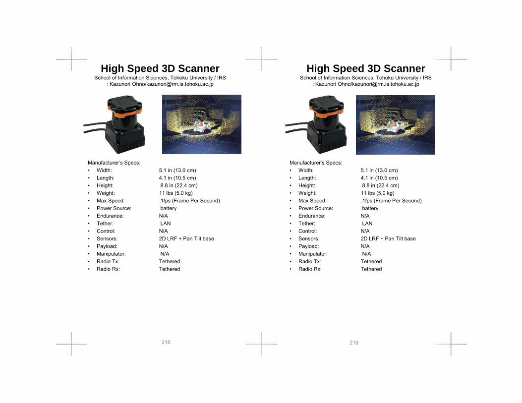
High Speed 3D Scanner School of Information Sciences, Tohoku University / IRS
: Kazunori Ohno/[email protected]
Manufacturer’s Specs: • Width: 5.1 in (13.0 cm)• Length: 4.1 in (10.5 cm)• Height: 8.8 in (22.4 cm)• Weight: 11 lbs (5.0 kg)• Max Speed: 1fps (Frame Per Second)
High Speed 3D Scanner School of Information Sciences, Tohoku University / IRS
: Kazunori Ohno/[email protected]
Manufacturer’s Specs: • Width: 5.1 in (13.0 cm)• Length: 4.1 in (10.5 cm)• Height: 8.8 in (22.4 cm)• Weight: 11 lbs (5.0 kg)• Max Speed: 1fps (Frame Per Second)
216216
Max Speed: .1fps (Frame Per Second)• Power Source: battery• Endurance: N/A• Tether: LAN• Control: N/A• Sensors: 2D LRF + Pan Tilt base• Payload: N/A• Manipulator: N/A• Radio Tx: Tethered• Radio Rx: Tethered
Max Speed: .1fps (Frame Per Second)• Power Source: battery• Endurance: N/A• Tether: LAN• Control: N/A• Sensors: 2D LRF + Pan Tilt base• Payload: N/A• Manipulator: N/A• Radio Tx: Tethered• Radio Rx: Tethered

Manufacturer’s Specs: • Width: 3.4 in • Length: 10.2 in• Height: 1.2 in• Weight: 1.75 lbs• Sensitivity: Cs-137: 90 cps/mR/h,
Co-60: 25 cps/mR/h,
ICS-4000 Radionuclide IdentifierXRF Corporation
www.xrfcorp.com / www.laurussystems.com
Manufacturer’s Specs: • Width: 3.4 in • Length: 10.2 in• Height: 1.2 in• Weight: 1.75 lbs• Sensitivity: Cs-137: 90 cps/mR/h,
Co-60: 25 cps/mR/h,
ICS-4000 Radionuclide IdentifierXRF Corporation
www.xrfcorp.com / www.laurussystems.com
Sens
ors
Sens
ors
217217
p ,Am-241: 2900 cps/mR/h
• Energy range: 10 keV – 2 MeV• Exposure rate range: 50 mR/h – 1 R/h• Response with angle if incidence: -3.3% 0 for -45 to
45 (Cs-137)• Type of detector: Solid state CdTe for
dose rate & radionuclide ID
• Data transmission type: Bluetooth• Battery type and lifetime: 24 hours• Display type: LCD w LED backlight• Alarm type: Audible & visual• Control: Remote / manual• Radio frequency immunity: Class A per standard
EN 61326 (1997) + A1 (1998) + A2 (2001)
• Radiated emission: Class B per standard EN 61326 (1997) + A1 (1998) + A2 (2001)
• Shock resistance: Conditional per ANSI N42.34

Inspector-1000Canberra Industrieswww.canberra.com
Manufacturer’s Specs:• Width: 7.5 in (19 cm)• Length: 6.5 in (16.5 cm)• Height: 2.5 in (6.4 cm)• Weight: 2.2 lbs (1.0 kg)• Sensitivity: (Cs-137, Co-60, Am-
241)
Inspector-1000Canberra Industrieswww.canberra.com
Manufacturer’s Specs: • Width: 7.5 in (19 cm)• Length: 6.5 in (16.5 cm)• Height: 2.5 in (6.4 cm)• Weight: 2.2 lbs (1.0 kg)• Sensitivity: (Cs-137, Co-60, Am-
241)
218218
)• Energy range: 50-3000 keV• Exposure rate range: 1000 mR/h• Response with angle if incidence: 95% from 0 for -45
to 45 (Cs-137)• Type of detector: GM + (either NaI(Tl) or
LaBr) with radionuclide ID
• Data transmission type: USB• Battery type and lifetime: 12, hours • Display type: LCD 320 x 200 Hi-res
color display• Alarm type: audible, visual• Control: eyes-on, manual• Radio frequency immunity: yes• Radiated emission: yes• Shock resistance: yes

Multibeam Imaging SonarMBI350-45
BlueVeiw Technologieswww.blueveiwtech.com
Manufacturer’s Specs:
• Specifications– Field of View: 45˚x 1°– Max Range: 90 ft– True Beam Width: 1˚x 1˚– Number of Beams: 256– Beam Spacing: 0.18°
R R l ti 016 i
Multibeam Imaging SonarMBI350-45
BlueVeiw Technologieswww.blueveiwtech.com
Manufacturer’s Specs: • Specifications
– Field of View: 45˚x 1°– Max Range: 90 ft– True Beam Width: 1˚x 1˚– Number of Beams: 256– Beam Spacing: 0 18°
Sens
ors
Sens
ors
219219
– Range Resolution: .016 in– Update Rate: Up to 40 Hz– Frequency: 1.35 MHz
• Mechanical Specifications– Weight in Air: 12.0 lb– Weight in Water: 3.2 lb– Depth Rating: 1000 ft– Size: 10.5 in x 9.2 in x 5.3 in
• Interface Specifications– Coms: Ethernet– Voltage: 12-48 VDC– Power: 15 Watts
Beam Spacing: 0.18– Range Resolution: .016 in– Update Rate: Up to 40 Hz– Frequency: 1.35 MHz
• Mechanical Specifications– Weight in Air: 12.0 lb– Weight in Water: 3.2 lb– Depth Rating: 1000 ft– Size: 10.5 in x 9.2 in x 5.3 in
• Interface Specifications– Coms: Ethernet– Voltage: 12-48 VDC– Power: 15 Watts

Multibeam Imaging SonarP450E-15
BlueVeiw Technologieswww.blueveiwtech.com
Manufacturer’s Specs: • Specifications
– Field of View: 45˚x 15°– Max Range: 450 ft– True Beam Width: 1˚x 15˚– Number of Beams: 256– Beam Spacing: 0 18°
Multibeam Imaging SonarP450E-15
BlueVeiw Technologieswww.blueveiwtech.com
Manufacturer’s Specs: • Specifications
– Field of View: 45˚x 15°– Max Range: 450 ft– True Beam Width: 1˚x 15˚– Number of Beams: 256– Beam Spacing: 0 18°
220220
Beam Spacing: 0.18– Range Resolution: 2 in– Update Rate: Up to 10 Hz– Frequency: 450 kHz
• Mechanical Specifications– Weight in Air: 5.7 lb– Weight in Water: 1.4 lb– Depth Rating: 1000 ft– Size: 9.6 in x 6.9 in x 4 in
• Interface Specifications– Coms: Ethernet– Voltage: 12-48 VDC– Power: 10 Watts
Beam Spacing: 0.18– Range Resolution: 2 in– Update Rate: Up to 10 Hz– Frequency: 450 kHz
• Mechanical Specifications– Weight in Air: 5.7 lb– Weight in Water: 1.4 lb– Depth Rating: 1000 ft– Size: 9.6 in x 6.9 in x 4 in
• Interface Specifications– Coms: Ethernet– Voltage: 12-48 VDC– Power: 10 Watts
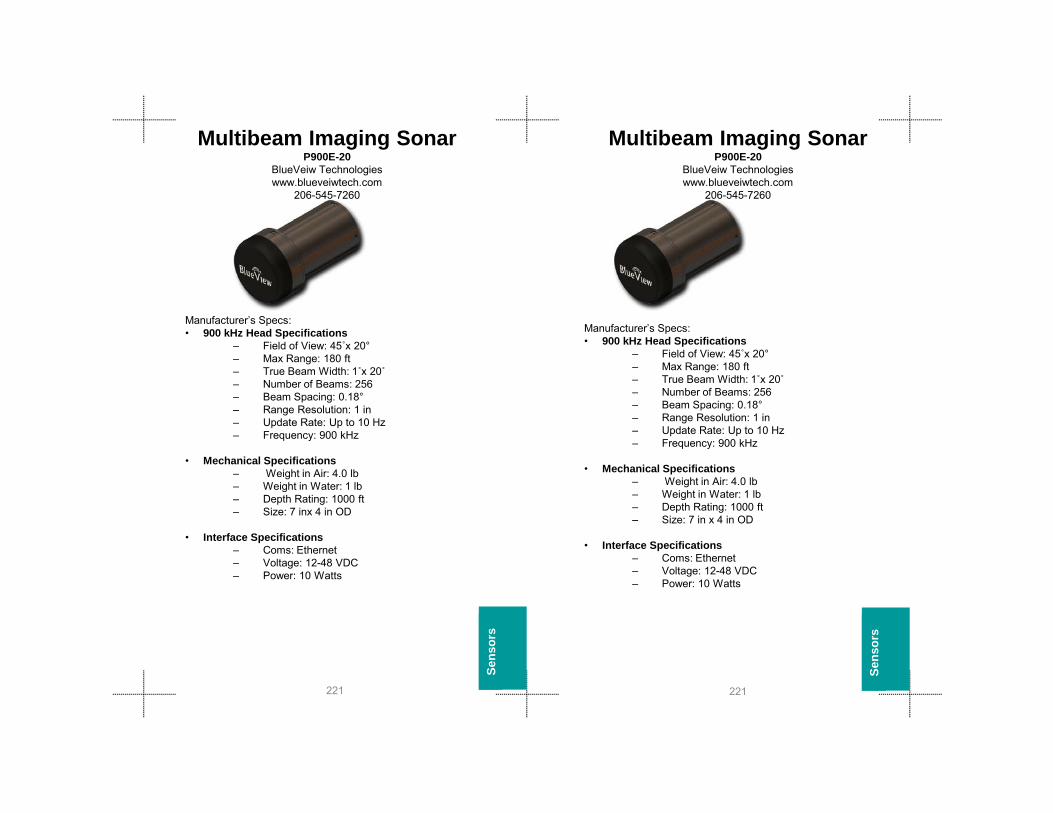
Multibeam Imaging SonarP900E-20
BlueVeiw Technologieswww.blueveiwtech.com
206-545-7260
Manufacturer’s Specs:• 900 kHz Head Specifications
– Field of View: 45˚x 20°– Max Range: 180 ft– True Beam Width: 1˚x 20˚– Number of Beams: 256– Beam Spacing: 0.18°
R R l ti 1 i
Multibeam Imaging SonarP900E-20
BlueVeiw Technologieswww.blueveiwtech.com
206-545-7260
Manufacturer’s Specs: • 900 kHz Head Specifications
– Field of View: 45˚x 20°– Max Range: 180 ft– True Beam Width: 1˚x 20˚– Number of Beams: 256– Beam Spacing: 0 18°
Sens
ors
Sens
ors
221221
– Range Resolution: 1 in– Update Rate: Up to 10 Hz– Frequency: 900 kHz
• Mechanical Specifications– Weight in Air: 4.0 lb– Weight in Water: 1 lb– Depth Rating: 1000 ft– Size: 7 inx 4 in OD
• Interface Specifications– Coms: Ethernet– Voltage: 12-48 VDC– Power: 10 Watts
Beam Spacing: 0.18– Range Resolution: 1 in– Update Rate: Up to 10 Hz– Frequency: 900 kHz
• Mechanical Specifications– Weight in Air: 4.0 lb– Weight in Water: 1 lb– Depth Rating: 1000 ft– Size: 7 in x 4 in OD
• Interface Specifications– Coms: Ethernet– Voltage: 12-48 VDC– Power: 10 Watts

Multibeam Imaging SonarBlueVeiw Technologieswww.blueveiwtech.com
206-545-7260
Manufacturer’s Specs: • 900 kHz Head Specifications
– Field of View: 45˚x 20°– Max Range: 180 ft– True Beam Width: 1˚x 20˚– Number of Beams: 256– Beam Spacing: 0.18°
R R l ti 1 i
Multibeam Imaging SonarBlueVeiw Technologieswww.blueveiwtech.com
206-545-7260
Manufacturer’s Specs: • 900 kHz Head Specifications
– Field of View: 45˚x 20°– Max Range: 180 ft– True Beam Width: 1˚x 20˚– Number of Beams: 256– Beam Spacing: 0.18°
R R l ti 1 i
222222
– Range Resolution: 1 in– Update Rate: Up to 10 Hz– Frequency: 900 kHz
• 2.25 MHz Head Specifications– Field of View: 45˚x 20°– Max Range: 15 ft– True Beam Width: 1˚x 20˚– Number of Beams: 256– Beam Spacing: 0.18°– Range Resolution: 0.4 in– Update Rate: Up to 10 Hz– Frequency: 2.25 MHz
• Mechanical Specifications– Weight in Air: 6.0 lb– Weight in Water: 1.5 lb– Depth Rating: 1000 ft– Size: 8.3 in x 5.0 in OD
• Interface Specifications– Coms: Ethernet– Voltage: 12-48 VDC– Power: 15 Watts

RadiogemCanberra Industrieswww.canberra.com
Manufacturer’s Specs:• Width: 5.9 in (15.0 cm)• Length: 3.3 in (8.5 cm)• Height: 1.8 in (4.5 cm)• Weight: .66 lbs(0.300 kg)• Sensitivity: yes (Cs-137, Co-
60, Am-241)
RadiogemCanberra Industrieswww.canberra.com
Manufacturer’s Specs: • Width: 5.9 in (15.0 cm)• Length: 3.3 in (8.5 cm)• Height: 1.8 in (4.5 cm)• Weight: .66 lbs(0.300 kg)• Sensitivity: yes (Cs-137 Co-
Sens
ors
Sens
ors
223223
, )• Energy range: 30 - 2000 keV (
probe dep. )• Exposure rate range: 0.03-10,000mR/h• Response with angle if incidence: 95% from 0 for -
45 to 45 (Cs-137)
• Type of detector: GM, or NaI, Plastic• Data transmission type: RS-232• Battery type and lifetime: 80 hours • Display type: LCD display• Alarm type: audible, visual• Control: eyes-on, manual• Radio frequency immunity: yes• Radiated emission: yes• Shock resistance: yes
Sensitivity: yes (Cs 137, Co60, Am-241)
• Energy range: 30 - 2000 keV ( probe dep. )
• Exposure rate range: 0.03-10,000mR/h• Response with angle if incidence: 95% from 0 for -
45 to 45 (Cs-137)
• Type of detector: GM, or NaI, Plastic• Data transmission type: RS-232• Battery type and lifetime: 80 hours • Display type: LCD display• Alarm type: audible, visual• Control: eyes-on, manual• Radio frequency immunity: yes• Radiated emission: yes• Shock resistance: yes

Swiss Ranger 4000Mesa Imaging AG/Acroname Inc.
www.acroname.com (US) / www.mesa-imaging.ch (Switzerland) Steve Richards ([email protected])
Manufacturer’s Specs: • Width: 2.6 in (6.5 cm) • Length: 2.6 in (6.8 cm) • Height: 2.6 in (6.5 cm) • Weight: 1.05 lbs (470 g) • Locomotion: None
Swiss Ranger 4000
Manufacturer’s Specs: • Width: 2.6 in (6.5 cm) • Length: 2.6 in (6.8 cm) • Height: 2.6 in (6.5 cm) • Weight: 1.05 lbs (470 g) • Locomotion: None• Steering: None
224224
• Steering: None• Turning Diam: None• Max Speed: 54 fps • Power Source: battery (12V) • Endurance: None• Tether: USB or Ethernet• Control: Mac, Linux, Windows Drivers• Sensors: 3D Depth Imaging
(176x144) pixel, 0.3 to 5.0 meter
• Payload: None• Manipulator: None
Steering: None• Turning Diam: None• Max Speed: 54 fps • Power Source: battery (12V) • Endurance: None• Tether: USB or Ethernet• Control: Mac, Linux, Windows Drivers• Sensors: 3D Depth Imaging
(176x144) pixel, 0.3 to 5.0 meter
• Payload: None• Manipulator: None

UltraRadiacCanberra Industrieswww.canberra.com
UltraRadiacCanberra Industrieswww.canberra.com
Manufacturer’s Specs: • Width: 2.61 in (6.6 cm)• Length: 3.95 in (10.0 cm)• Height: 1.14 in (2.9 cm)• Weight: .6 lbs (0.269 kg)• Sensitivity: yes (Cs-137 Co-
Manufacturer’s Specs: • Width: 2.61 in (6.6 cm)• Length: 3.95 in (10.0 cm)• Height: 1.14 in (2.9 cm)• Weight: .6 lbs (0.269 kg)• Sensitivity: yes (Cs-137, Co-
60 A 241)
Sens
ors
Sens
ors
225225
Sensitivity: yes (Cs 137, Co60, Am-241)
• Energy range: 60 - 1300 keV• Exposure rate range: 0.001 – 500,000
mR/h • Response with angle if incidence: 95% from 0 for -
45 to 45 (Cs- 137)• Type of detector: GM• Data transmission type: RS-232• Battery type and lifetime: 150 hours • Display type: LCD display• Alarm type: audible, visual,
vibration• Control: yes-on, manual• Radio frequency immunity: yes• Radiated emission: yes• Shock resistance: yes
60, Am-241) • Energy range: 60 - 1300 keV• Exposure rate range: 0.001 – 500,000
mR/h • Response with angle if incidence: 95% from 0 for -
45 to 45 (Cs- 137)• Type of detector: GM• Data transmission type: RS-232• Battery type and lifetime: 150 hours • Display type: LCD display• Alarm type: audible, visual,
vibration• Control: yes-on, manual• Radio frequency immunity: yes• Radiated emission: yes• Shock resistance: yes

226226

General IndexContact Information 3
Program Overview 4
Events
2010-Disater City 6
College Station, TX
2008-Disater City 22
College Station, TX
2007-Disater City 26
College Station, TX
2006-MD TF-1 30
Rockville, MD
2006-Disaster City 34
General Index
Contact Information 3
Program Overview 4
Events
2010-Disater City 6
College Station, TX
2008-Disater City 22
College Station, TX
2007-Disater City 26
College Station, TX
2006-MD TF-1 30
Rockville, MD
2006-Disaster City 34
227227
College Station, TX
Safety 41
Test Methods 43
Ground Robots 139
Wall Climbers 193
Aerial Robots 197
Aquatic Robots 209
Sensors 212
y
College Station, TX
Safety 41
Test Methods 43
Ground Robots 139
Wall Climbers 193
Aerial Robots 197
Aquatic Robots 209
Sensors 212

Index-Size Index-SizeRobot Name CompanyGround Robots
Recon Scout ReconRobotics 140Eyeball R1 O.D.F. 141ToughBot Omnitech Robotics 142Active Scope Camera Tohoku University 143Pointman (LRV) Applied Research Assoc. 144VGTV-Exteme Inuktun 145Dragon Runner Foster-Miller/Automatika 146BomBot WVHTC 147Versatrax 100 Inuktun 148G2Bot Mesa Robotics 149Marv Mesa Robotics 150Souryu IV IRS 151Souryu IRS 152BomBot 2 WVHTC 153Souryu V IRS 154Jacobs Rugg.Robot Jacobs University 155
Robot Name CompanyGround Robots
Recon Scout ReconRobotics 140Eyeball R1 O.D.F. 141ToughBot Omnitech Robotics 142Active Scope Camera Tohoku University 143Pointman (LRV) Applied Research Assoc. 144VGTV-Exteme Inuktun 145Dragon Runner Foster-Miller/Automatika 146BomBot WVHTC 147Versatrax 100 Inuktun 148G2Bot Mesa Robotics 149Marv Mesa Robotics 150Souryu IV IRS 151Souryu IRS 152BomBot 2 WVHTC 153Souryu V IRS 154Jacobs Rugg.Robot Jacobs University 155
228228
Element Mesa Robotics 156Hero First Response Robotics 157Super Kenaf IRS 158UMRS2009 IRS 159Kenaf IRS 160PackBot Explorer iRobot 161Hibiscus Toin 162Cphea Toin 163Robbie 6 University Koblenz-Landau 164Shinobi Univer. Electro Comm. 165Quince IRS 166PackBot iRobot 167Matilda Mesa Robotics 168Matilda II Mesa Robotics 169PackBot EOD iRobot 170PackBot 510-EFR iRobot 171NuTech-R-4 Nagaoka Univ. Tech. 172
Element Mesa Robotics 156Hero First Response Robotics 157Super Kenaf IRS 158UMRS2009 IRS 159Kenaf IRS 160PackBot Explorer iRobot 161Hibiscus Toin 162Cphea Toin 163Robbie 6 University Koblenz-Landau 164Shinobi Univer. Electro Comm. 165Quince IRS 166PackBot iRobot 167Dig.Vanguard Allen Vanguard 168Matilda Mesa Robotics 169Matilda II Mesa Robotics 170PackBot EOD iRobot 171PackBot 510-EFR iRobot 172NuTech-R-4 Nagaoka Univ. Tech. 164

Index-Size Index-SizeRobot Name CompanyGround Robots Cont.
Helios IX IRS 173 KOHGA IRS 174Versatrax 150 Inuktun 175Talon Gen IV Qinetiq/Foster-Miller 176Talon Hazmat Qinetiq/Foster-Miller 177Talon Shoulder Qinetiq/Foster-Miller 178Chaos Autonomous Solutions, Inc. 179Dig.Vanguard Allen Vanguard 180Modular Logistics Platform Segway 181ATRV mini Idaho National Lab 182RMP 200 Segway 183TeleMax TeleRob 184Caliber ICOR Tech 185HD-1J Remotec 186Mini-Andros II Remotec 187RMP 400 Segway 188Andros F6A Remotec 189Cetaur MITRE 190Boz I BOZ Robotics 191
Robot Name CompanyGround Robots Cont.
Helios IX IRS 174KOHGA IRS 175Versatrax 150 Inuktun 176Talon Gen IV Qinetiq/Foster-Miller 177Talon Hazmat Qinetiq/Foster-Miller 178Talon Shoulder Qinetiq/Foster-Miller 179Chaos Autonomous Solutions, Inc. 180Modular Logistics Platform Segway 181ATRV mini Idaho National Lab 182RMP 200 Segway 183TeleMax TeleRob 184Caliber ICOR Tech 185HD-1J Remotec 186Mini-Andros II Remotec 187RMP 400 Segway 188Andros F6A Remotec 189Cetaur MITRE 190Boz I BOZ Robotics 191
Wall Climbers
229229
Wall ClimbersVMRP Vortex 194NanoMag Inuktun 195
Aerial RobotsFixed Wing
Nighthawk Applied Research Assoc. 198
Raven AeroVironment Inc. 199Dragon Eye AeroVironment, Inc. 200CyberBug Cyber Defense Systems, Inc. 201Evolution-XTS L-3 BAI Aerosystems, Inc 202
RotorMicro-Drone 200 BCB International, Ltd. 203AirRobot AirRobot 204Flying Bassett Univ. of AL – Huntsville 205Yamaha Helicopter Skeyes Unlimited 206
OtherBlimp ARACAR 207
VMRP Vortex 194NanoMag Inuktun 195
Aerial RobotsFixed Wing
Nighthawk Applied Research Assoc. 198
Raven AeroVironment Inc. 199Dragon Eye AeroVironment, Inc. 200CyberBug Cyber Defense Systems, Inc. 201Evolution-XTS L-3 BAI Aerosystems, Inc 202
RotorMicro-Drone 200 BCB International, Ltd. 203AirRobot AirRobot 204Flying Bassett Univ. of AL – Huntsville 205Yamaha Helicopter Skeyes Unlimited 206
OtherBlimp ARACAR 207

Aquatic RobotsVideoRay Pro 3 VideoRay 210LBV200L2 SeaBotix 211LBV150SE-5 SeaBotix 212
Index-Size Index-Size
Aquatic RobotsVideoRay Pro 3 VideoRay 210LBV200L2 SeaBotix 211LBV150SE-5 SeaBotix 212
230230

Index- SensorsdcMap 214GammaRAE II Responder 215High Speed 3D Scanner 216ICS-4000 Radionuclide Identifier 217Inspector-1000 218Multibeam Imaging Sonar
MBI350-45 219P450E-15 220P900E-20 221Multibeam Imaging Sonar 222
Radiogem 223Swiss Ranger 4000 224UltraRadiac 225
Index- SensorsdcMap 214GammaRAE II Responder 215High Speed 3D Scanner 216ICS-4000 Radionuclide Identifier 217Inspector-1000 218Multibeam Imaging Sonar
MBI350-45 219P450E-15 220P900E-20 221Multibeam Imaging Sonar 222
Radiogem 223Swiss Ranger 4000 224UltraRadiac 225
231231