robotic work cell for packing canisters
TRANSCRIPT
Rochester Institute of Technology Rochester Institute of Technology
RIT Scholar Works RIT Scholar Works
Theses
12-1-1986
Robotic work cell for packing canisters Robotic work cell for packing canisters
Robert J. Makar
Follow this and additional works at: https://scholarworks.rit.edu/theses
Recommended Citation Recommended Citation Makar, Robert J., "Robotic work cell for packing canisters" (1986). Thesis. Rochester Institute of Technology. Accessed from
This Thesis is brought to you for free and open access by RIT Scholar Works. It has been accepted for inclusion in Theses by an authorized administrator of RIT Scholar Works. For more information, please contact [email protected].

ROBOTIC WORK CELL FOR PACKING CANISTERS
by
Robert J. Makar
in
Partial Fulfillment
of the
Requirements for the Degree of
MASTER OF SCIENCE
in
Mechanical Engineering
Approved by: Prof. Wayne W. Walter
- --------------(Thesis Advisor)
Prof. _N_a_m_e_lIl_e-=9_ib_l_e ___ -.'/,.A-sS"P'": Ptu?
Prof. Chris F. Nilsen
Prof. B. V. Karlekar ----------.---------{Department Head)
DEPARTMENT OF KECHABICAL ENGINEERING
COLLEGE OF ENGINEERING
ROCHESTER IHS~I~UTl OF ~ECHNOLOGY
ROCHES~ER, NEW YORK
DECEMBER 1986
_R_o_b_e_r_t_J_. _M_a_k_a_r ________ hereb~ Gra~ iny) permission to the Wallace Memorial Library, of R.I.T., to
~ro~ce my thesis in whole or in part. Any reproduction ~ill
)t be for commercial use or profit.
ACKNOWLEDGEMENT
I would like to express my gratitude to all those who
assisted me in the completion of this endeavor. My special
thanks goes to Dr - Wayne Walter, my thesis adviser, for his
encouragement and guidance during the development of this
project. I would also like to thank those at Rochester Products,Cliff Ratza, Greg Wielnau, John Goebel, Emily Abrams and Joe
Cocca for making available to me their time, knowledge and
resources which were necessary for the completion of this
project. Finally, I would like to thank Idette Espinosa for her
deligent efforts in typing this report.
ABSTRACT
The purpose of this project is to reduce the manufacturing
cost of the special order 2500cc truck canisters produced at
RochesterProducts'
Lee Road facility. This was accomplished by
designing and developing a robotic work cell to pack the
canisters into baskets at the injection mold machine. A
literature search was conducted to gain a broader understanding
of robotic applications and end-effector design. In developingthis cell, the layout of the work cell components was
determined, a suitable robot was selected, and an end-effector
was designed, built and tested.
TABLE OF CONTENTS
CHAPTER I : INTRODUCTION PAGE 1
CHAPTER II : PROBLEM & TASK DESCRIPTION PAGE 10
CHAPTER III : SIMILAR APPLICATIONS
AND APPLICATION IDEAS PAGE 12
CHAPTER IV : ROBOTIC WORKCELL
DESIGN CONSIDERATIONS PAGE 18
CHAPTER V : PROPOSED ROBOTIC WORKCELL PAGE 2 2
CHAPTER V.a : COMPONENTS PAGE 2 2
CHAPTER V.b : ROBOT SELECTION PAGE 36
CHAPTER VI : END-EFFECTOR, OVERVIEW, DESIGN,BUILD & TEST PAGE 42
CHAPTER VI . a : OVERVIEW PAGE 42
CHAPTER VI. b: END-EFFECTOR DESIGN FOR PACKING
CANISTERS PAGE 46
CHAPTER VII : SUMMARY AND CONCLUSION PAGE 62
REFERENCES PAGE 7 0
APPENDICES PAGE 73
l l

LIST OF TABLES
Table 1 : Various Applications for Different Types
of Robots Page 5
Table 2 : Types of Robotic Power Systems Page 6
Table 3 : Advantages & Disadvantages of
Robot Types for Palletizing Page 16
Table 4 : The Comparison of Three Robots Page 37
IV
CHAPTER I: INTRODUCTION
Robots have been quickly accepted in the industrial world as
highly successful tools for increasing productivity. Since
robots are fairly new and important to industry, it was the
author's hope to learn more about robots and how to successfullyimplement them.
Today's markets are changing more rapidly than in the past.
Because of these rapid changes, industry has been finding it
difficult to economically change over its hard tooled, dedicated
manufacturing systems. In many industries it is no longer cost
justifiable to build large high volume production equipment to be
scrapped in a few years due to market changes. The strongest
quality robots have to offer to the world of manufacturing is
that they can be retooled and reprogrammed to handle changes in
production requirements at a relatively low cost. {1}*
Another important reason why robots are becoming popular is
their ability to work continuously without taking a break,
starting late, or calling in sick. Thus they are continuouslyproductive. Robots also have very high repeatability which
allow them to produce a very high quality product since it is
unlikely they will make a mistake. Hence, the scrap rate is
lowered, driving the product cost down. High repeatability also
allows for less material waste in operations such as welding and
spray painting, because robots can be programmed to accurately
repeat a sequence of steps. {2}
Robots relieve workers from less desirable jobs. They can
easily handle many dull and monotonous jobs which workers are
currently assigned. In dangerous work environments robots are
unaffected by toxic chemicals, high temperatures and high levels
of contaminants .{ 3}
Just as robots are suitable for many tasks, there are many
manufacturing situations which are better handled by other
manufacturing techniques, including hard automation and manual
labor .
Robots vs. Hard Tooled Automation and Manual Labor
The methods by which a product can be manufactured can be
divided into three separate categories which are: hard tooled
automation, roboticwork cells, and manual labor. Hard tooled
automation is defined as a system of tools working together in a
synchronous fashion. It is also referred as dedicated tooling,
* - All numbers in brackets {} are reference numbers
given on page 70.

that is, tooling which is dedicated to produce one product. The
next type, robotic work cells, are ideally set up to produce a
particular product until the production run is complete. After
the run is complete, the cell is reconfigured to produce a
different product. Finally, manual labor is defined as those jobs
for which an operator does the majority of the work. For the
sake of comparison, we will consider manual labor to handle tasks
which are essentially piece-work.
An illustrative way of understanding the effectiveness of
each manufacturing technique is to compare the cost of producing
a single part as a function of the production run volume. This
is shown in Figure l.{4>
1 Cost Per Unit
Hard Tooled
Automation
Manual
Labo]
A A A A A
r
1
Manual
Labor
Most
Cost
Effective
Hard Tooled
Automation
Most Cost
Effective
Figure 1:
Unit Volume
Manufacturing Cost Comparison
This chart illustrates that if a small number of parts are
going to be produced, it is most cost effective to use manual
labor since minimal capital expenditures are required. On the
other hand, if a relatively large number of parts are to be
produced, hard tooled automation would be the most cost effective
method. Finally, robotics is most cost effective if used in
medium volume jobs since a robot's implementation is less costly
than automation production line. Thus, less parts have to be
produced by a robot work cell in order to earn a pay back. {5}
A robot is well suited for batch processing where a job runs
for a predetermined period of time(i.e. 1 shift, 1 week, 3
months). At the end of the batch, the robot can be retooled and
reprogrammed to run the next batch of parts. Compared to hard
tooled automation, a robot can be changed over very quickly to
handle the next production run. {6} A robot is also well suited
for applications which require the dexterity that hard tooled
automation cannot provide. The work cell environment, however
must be very structured to ensure that the"blind"
robot will be
able to find what it is seeking. {7}
Examples of Robot Tasks
Today, robots are performing many tasks throughout
industry. Below is a listing of the different areas in which
robots are being currently used.
-
Welding : Spot, MIG, TIG
-
Painting : Spray
- Material : Machine loading/unloading,
Handling parts transfer, parts sorting,
palletizing, part manipulation
during a manufacturing operation
-
Tooling : Drilling, cleaning, deburring, material
removal operations
- Inspection : Digital vision systems, laser
inspection, sorting out rejects
-
Assembly ' Electronic components, automotive
components, consumer appliances

Basic Types of Robots
Robots are categorized by the type of coordinate system used
to describe its arm's end point in free space. The five major
types of robots are Cartesian Coordinate, Cylindrical Coordinate,
Spherical Coordinate, Fully Articulated, and Scara configuration.
Figure 2 shows a diagram of each type of robot. {8}
Spherical Coordinate Robot
Articulated Robot
Cylindrical Coordinate Robot
i -
; i
1 ^o^^
EfMi i> i
is i i
i
i
Ms
1S3E iI i
I i
-4~ !
Figure 2: Different Robot Configurations

Below is a table showing the different tasks each type of
robot is best suited for.
Table 1: Various Applications for Different Types of Robots
ROBOT APPLICATION
Cartesian
Coord .
- Machine Loading- Material Handling
Cyl indr ical
and
Spherical
Coord .
- Material Handling- Machine Loading-
Tooling and Inspection
FullyArticulated
-
Spray Painting-
Welding- Sealant Application
-
Deburring-
Drilling- Material Handling- Machine Loading-
Tooling and Inspection
SCARA
Configu
ration
- Small Parts Handling-
Assembly- Electronic Assembly- Small Materials Handling
The more articulated the robot, the higher the number of
tasks it is capable of doing. With this added dexterity,
however, comes a higher price. Thus if only a very simple task
needs to be done, one may consider using the simplest type of
robot available that can do the task.
The three different types of power systems typically used
for robots are hydraulic, pneumatic, and electrical systems. The
three tables which follow show the advantages and disadvantage of
each power system.

Table 2a.: Hydraulics
ADVANTAGES DISADVANTAGES
Remote power source -Complicated positional
control and servo
-High power-to-weight feedback system
ratio
-Difficult to maintain
-High power to volume
ratio -Power source takes up
additional floor space
-Minimal weight on
manipulator -Very sensitive to dirt
or foreign particles
-Medium priced systems in the fluid system
-Fluid systems leak
and may be unacceptable
afor many applications
Table 2b.: Pneumatic
ADVANTAGES DISADVANTAGES
-Remote power source
-Can tolerate a more
industrial environment
than a hydraulic system
-Inexpensive system
-Power source requires
additional floor space
-Poor power-to-weight
ratio
-No servo feedback or
positional controls
-Poor power-to-volume
ratio

Table 2c, Electric
ADVANTAGES DISADVANTAGES
-Very tolerant in an -Power source is on
industrial environment the manipulator thus
decreasing effective
-Excellent positional payload
and repeatabilitycapabilities -New technology and
current maintenance
-Good power-to-weight staff may need time to
ratio learn the control sys .
-Rapid response time -Higher cost
-Minimum contamination -Not suitable for
problems explosive environments
Depending on the application, the robot's power system
should be considered first. For example, if the robot is to move
heavy objects, a hydraulic power system will provide the
necessary payload capacity. However, if the robot is to be used
in a clean room of an electronics facility, a hydraulic system
will not be acceptable due to potential hydraulic fluid leakage;whereas an electrically powered robot will be well suited.
Controller System
The two most
motion are the point
method. A robot
from one point in fr
an arbitrary path.
is usually the quick
start and stop si
longest time to comp
the others move at a
finish concurrently.
popular methods used to control a robot's
-to-point method and the continuous path
which uses the point-to-point method travels
ee space to a second point in free space on
The path taken may not be the shortest but it
est. The drives on each of the robot's axes
multaneously. The joint which requires the
lete the maneuver moves at full speed while
slower speed so the motion on all the joints
{9>
A robot which uses the continuous path method has a defined
motion through free space. The path end points and the path
itself must be programmed. The drives on each of the axes,
therefore, activate in a coordinated and synchronous fashion.
Most continuous path robots are used in applications such as
welding and spray painting .{ 10}
Programming Methods
The major advantage a robot has over other types of
manufacturing equipment is its ability to be reprogrammed . The
three methods of programming a robot are the teach pendant
method, off-line programming method, and the free-world teach
mode method. The teach pendant method is the most common of the
three, and almost all early industrial robots were programmed
using this method. As robots and controller technology
progressed, off-line programming became available. The newest way
to program robots is the free-world teach mode.
The teach pendant is a direct communication link to the
robot's controller giving the programmer full control over the
robot's motion. Using the controls on the teach pendant, the
programmer positions the robot as well as he can by eye. Next the
programmer depresses a"teach"
button signaling the controller
that this is a point the robot must reach during normal
operation. Once fully programmed, the robot will repeat the
sequence until it is reprogrammed. This method has the advantage
of the programmer being close to the robot to see the position of
the robot relative to the work cell. It is difficult, however,to precisely position the robot. This method is also not all that
safe. In addition, production must be interrupted for
reprogramming . {11}
The off-line programming method requires the programmer to
sit down behind a CRT and to program, in code, the movements of
the robot. A sequence of code might be like this :
0001 GOTO PT (X1,Y1,Z1)
0002 ROTATE THETA (1.570)
0003 CLOSE (0.1250)
0004 GOTO PT (X1,Y1,Z2).
The GOTO command means the end of the manipulator must go to
that point in space. The ROTATE THETA command means rotate the
wrist along the theta axis 1.570 radians. The CLOSE means the
jaw would close 0.1250 inches. And finally, the last GOTO
command would mean to go to the second point in space.
The major advantage of off-line programming is that the
robot can be programmed away from the factory floor and doesn't
interrupt production. Using this method, the routines can be
easily edited. Small subroutines can be added and deleted to
adjust the whole system slightly to compensate for such things as
changes in the product or production, changes in the work
environment (i.e.: displaced parts positioners or other external
hardware) and changes in operating parameters (i.e.: faster
welding speeds). The major disadvantage to this system is the
programmer may have difficulty in"seeing"
what he is
programming. But with the recent developments in multi-color
computer graphics, this problem is becoming of lesser
concern . {12 }
The newest technique in programming is the free-world teach
mode programming method. This method needs only a short set-up
time and is easy to use. With the robots drive mechanism in
neutral, the robot is manually moved to the correct position and
a"teach"
button is depressed signaling the robot to come to this
point at this step in the sequence. The method has the same
disadvantage as the teach pendant method since the positional
accuracy is dependent upon the programmer. However, the robot
can be quickly repositioned and taught a new point. This
quickness makes the free-world teach mode very attractive for the
development environment when several different manipulation
sequences are to be compared .{ 13}
Several newer robot systems incorporate all three
programming methods. This allows the programmer to utilize the
advantages of all three techniques.
CHAPTER II PROBLEM AND TASK DESCRIPTION
The purpose of this work was to develop and design a robotic
work cell to palletize Rochester Product's 2500cc fuel canister
after injection molding. In addition to developing the
cell, the robot's end effector was designed, built and tested.
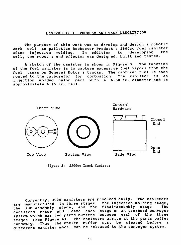
A sketch of the canister is shown in Figure 3. The function
of the fuel canister is to capture excessive fuel vapors from the
fuel tanks on General Motor's trucks. The captured fuel is then
routed to the carburetor for combustion. The canister is an
injection molded nylon part with a 6.50 in. diameter and is
approximately 6.25 in. tall.
Inner-Tube
Control
Hardware
Closed
End
Top View Bottom View Side View
Open
End
Figure 3: 2500cc Truck Canister
The canisters
.
* ', j_ .-1 _. _. *-U*> 4 n 4o/-4- i An .
ai
th
c<
S]si
randomly. Thus, the
model can be released to the conveyer system.different canister
10

The requirement that the
logistics problem when a small lo
produced. Normal production lo
day and the time to clear the part
small lots must be produced con
yet remain physically segregated.
different lots, each small lot
between production stages in large
loaded and unloaded at each o
necessitates one person per shift
additional staff just for smal
objective of this project was to
labor required to produce the smal
buffer be cleared creates a
t (500-1000 pieces) must be
ts are in the order of 3000 per
s buffer is about 4 hours. The
current with normal production.
To maintain separation of
of canisters are transported
baskets which are manually
f the three stations. This
at each of the stations as
1 lot production. Thus, the
reduce the amount of manual
1 lots canisters.
It was proposed to automate th
the basket at the injection molding ma
work cell. One work cell was in
favorable technical and financi
modifications, the remaining two wo
assembly line would be implemented.
included the injection molding machin
be loaded with canisters, and a test s
included to insure 100* inspection of
went to the sub-assembly stage. This
company of the highest quality canis
problem of small lot production.
e loading of
chine by usi
itially plan
al evaluat
rk cells for
The propos
cam
ng
ned
ion
the
ed
e, the robot, the
st
ts b
on a
s a
tand. The tes
the small lo1
100* inspecti*
ters which was
sters into
a robotic
and after
and/or
subsequent
work cell
basket to
stand was
efore theyssured the
particular
Injection
Mold
Machine
Sub-
AssemblyLine
Final
AssemblyLine
Figure 4: Production Flow Path
11
CHAPTER III SIMILAR APPLICATIONS
AND APPLICATION IDEAS
As with most design projects, it is imperative to thoroughlyresearch the subject matter before design begins. Presented here
are the findings of a literature search on robotic work cells.
The two main categories which were investigated are robotic
machine loading/unloading and robotic palletizing operations.
Machine Loading/Unloading
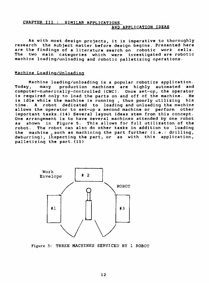
Machine loading
Today, many prod
compute r-numer icallyis required only to
is idle while the ma
time. A robot ded
allows the operator
important tasks. {14}
One arrangement is t
as shown in Figur
robot. The robot ca
the machine such a
deburring), inspecti
palletizing the part
/unlo
uctio
-cont
load
chine
icate
to se
Seve
o hav
e 5.
n als
s mac
ng th
. {15}
ading
n mac
rol led
the pa
i s ru
d to
t-up a
ral la
e seve
This
o do o
hininge part
is a popular
hines are
(CNC). One
rts on and o
nning ,thus
loading and
second mach
yout ideas s
ral machines
allows for f
ther tasks i
the part fu
, or as wi
robotics appli
highly automat
e set-up, the o
ff of the machi
poorly utilizi
unloading the
ine or perform
tern from this c
attended by on
ull utilization
n addition to
rther (i.e.: dr
th this appli
cation .
ed and
perator
ne . He
ng hi s
machine
other
oncept .
e robot
of the
loadingi 11 ing ,
cation,
Work
Envelope # 2
#1
fiROBOT
#3
Figure 5: THREE MACHINES SERVICED BY 1 ROBOT
12
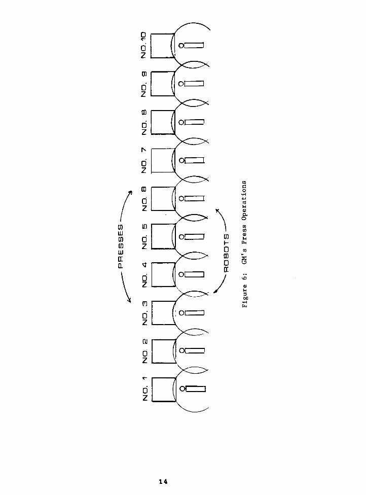
At General Motors, for example, ten punch presses in series
are required to bring a sheet metal part to its final shape. As
originally set up, each of the ten presses had an operator. The
part was manually placed in the press, the unit was activated,
the part removed and passed to the next station. This punch press
line was reconfigured and now there is a robot at each press
station putting the parts into the press, removing them, and then
passing it to the next robot as shown in Figure 6. The robots
used in this application are the GMF M-1A robot, an electrically
powered cylindrical coordinate robot.
The new robotic punch press line produces parts at a slower
rate than the manned line, but the daily output of the line has
increased. This is because the robots work continuously through
all breaks and shift changes, and the reduction of scrap rate due
to therobots'
high repeatability.
The last robot of the sequence also loads the parts into
baskets (these baskets are very similar to the ones which will be
used in this project). To allow a better reach capability, the
front gate on the basket is folded down. To assist with the
loading of the parts, the end-effector has been designed to place
cardboard separators between each layer of parts.
To ensure that the production flow is not interrupted, two
baskets are made available for the last robot to pack. When the
first basket is full, the punch press line continues to run with
the last robot now packing the second basket. The full baskets
are removed by the set-up man and replaced with empty ones. {16}
When using a robot in a machine tending application, as in
the above example, cycle time must be considered. The cycle time
of the robot and the machine(s) should be fairly well matched. A
major factor affecting a robot's speed (cycle time) is the
accuracy which the robot must achieve. {17}
Accurate positioning of a part by a robot requires a
significant amount of time since the robot needs to slow down and
approach that point in very small steps. This is because the
controller needs more time to compute the position of the
manipulator. The use of a secondary positioning device would
eliminate the need for the robot to accurately position the part
itself. The robot would drop off the part and the secondary
device would position the part. A secondary device adds to the
cost of the work cell and needs to be considered to ensure that
the work cell remains cost justifiable.
Also, when using a robot in a machine tending operation,
area allotment needs to be considered. It is important to
minimize the amount of area which the robotic work cell will
occupy since factory floor space is limited and very expensive.
On the other hand squeezing the work cell tightly together makes
it difficult for the maintenance personnel to access the machines
13
CD
UJ
Cfi
Cfl
UJ
tr
a
CO
0
z
y^
01 [
CD
co
M
HI
a
o
w
CO
QJ
U
Ol,
h
360
H
fa
14

or the robot. It is also advisable to leave enough room in the
cell for an operator to take over the operation if the robot
breaks down. This is particularly important in a manufacturing
system where continuous work flow is essential .{ 18}
The GeneralMotors'
robotic punch press line is an
application where the work cell has been arranged to allow
operators to easily take over the robot's task. All of the
robots are mounted on wheels so that in the event that one fails,it can be removed from the line and an operator can step in to
take over the operation. This prevents all ten punch presses and
the remaining robots from becoming idle. {19}
Palletizing
"Automated material handling systems are the backbone of
future automation in the factory "{20} An automated factoryneeds a well ordered environment where materials are accuratelylocated and oriented thus minimizing the amount of material
handling in the production process. Good positional and
orientative accuracies help"blind"
tools, such as robots, to
always find the part. An orderly environment also ensures
quicker material flow since the parts do not have to be
manipulated. Palletizing systems offer an excellent means of
achieving this orderly environment . {21 }
Several items which should be considered before introducinga pallet or palletizing system into a robotics work cell are
system duplication, the use of separator trays, and cycle time.
If a robotic palletizing system is currently in place at the
designer's facility, it should be duplicated if that system is
workingsatisfactorily. This duplication has the benefits of
having the technical expertise and spare parts already in place.
This will make the new implementation more efficient and less
costly. {22}
Specialized separator trays are being widely used throughout
industry. The use of specialized separator trays has several
advantages. They increase theparts'
three-dimensional positional
accuracy and maintain their orientation during transportation.
The trays also help to minimize part damage and present an
effective means for inventory control. Some of the draw backs of
using trays are that they need to be stored and inspected prior
to use, and the propagation of inaccuracies as the trays are
stacked upon one another. {23}
In most cases, the given production rate is invariable which
determines how many parts the robot must handle at once. If the
robot is slow compared to the production rate, it will have to
handle two or more parts simultaneously. This leads to new
problems such as how to handle multiple parts and how they are to
15
be palletized. On the other hand, if the robot
than the production rate, the robot may be able
additional task while waiting on the primary task.
is much faster
to handle an
An important task a robot may handle if it
the placement of the separator trays. Once a sepa
full, the robot retrieves another tray and pu
This simplifies the work cell since it will not be
have a secondary device to handle the trays. The
be better utilized. To help facilitate the pla
trays by the robot, a parts buffer may be used all
to accumulate while the robot is putting the empty
Once the tray is in position, the robot will st
parts at a faster pace until the buffer is empty. {
has the time is
rator tray is
ts it in place.
necessary to
robot will also
cement of the
owing the parts
tray in place.
art loading the
24}
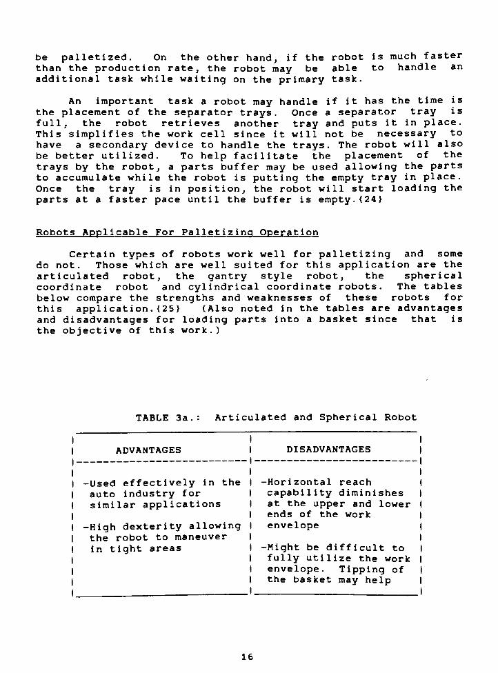
Robots Applicable For Palletizing Operation
Certain types of robots work well for palletizing and some
do not. Those which are well suited for this application are the
articulated robot, the gantry style robot, the spherical
coordinate robot and cylindrical coordinate robots. The tables
below compare the strengths and weaknesses of these robots for
this appl ication . {25 } (Also noted in the tables are advantages
and disadvantages for loading parts into a basket since that is
the objective of this work.)
TABLE 3a Articulated and Spherical Robot
ADVANTAGES DISADVANTAGES
-Used effectively in the -Horizontal reach
auto industry for capability diminishes
similar applications at the upper and lower
ends of the work
-High dexterity allowing
the robot to maneuver
in tight areas
envelope
-Might be difficult to
fully utilize the work
envelope. Tipping of
the basket may help
16
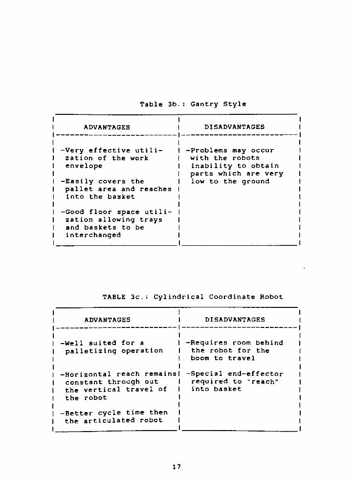
Table 3b.: Gantry Style
ADVANTAGES DISADVANTAGES
-Very effective utili -Problems may occur
zation of the work with the robots
envelope inability to obtain
parts which are very
-Easily covers the low to the ground
pallet area and reaches
into the basket
-Good floor space utili
zation allowing trays
and baskets to be
interchanged
TABLE 3c: Cylindrical Coordinate Robot
ADVANTAGES DISADVANTAGES
-Well suited for a
palletizing operation
-Horizontal reach remains
constant through out
the vertical travel of
the robot
-Better cycle time then
the articulated robot
-Requires room behind
the robot for the
boom to travel
-Special end-effector
required to"reach"
into basket
17

CHAPTER IV : ROBOTIC WORK CELL
DESIGN CONSIDERATIONS
The objective of this section is to point out several
considerations which are important in the development of a
robotic work cell. The topics that are discussed are preliminary
survey, floor plan layout and safety.
Preliminary Survey of Application
The best way to implement a robotic work cell is to survey
the task and develop a flow chart for all the steps involved.
This helps the designer to clearly understand the entire task.
The flow chart should include all actions which will be performed
(i.e.: grasp, move, rotate, home), all feedback signals (i.e.:
begin cycle, discontinue cycle, emergency stop, end-effector
sensory feedback), and all utility steps (i.e.: home, signal
output due to system failure, statistics outputs). After the
flow chart has been developed and reviewed, the time for each
step should be accurately determined. This will reveal any cycle
time problems^ early in the development stage. {26}
Next, the flexibility of the robotic work cell needs to be
considered. The work cell may have to accommodate changes in the
product which could be tolerance differences or designed changes
in the part. The work cell may also need to accommodate changes
in the production rate. And for future use, the system may have
to communicate with other equipment which will ease the way for a
fully automated factory. {27}
The next point of consideration is to determine what type of
robot is most feasible for the particular application. To do
this, an in-house audit should be conducted of the plant
personnel to understand what robot will work best in the
designer's facility. For example, if the maintenance personnel
are unfamiliar with complicated hydraulic system but are familiar
with servomotors, it would be best to use an electrically powered
robot over a hydraul ically powered robot. {28}
One of the last things which should be considered is the
intensity of communication required by the work cell. By
examining a
it is easy to determine tne amount oi miorraanon wnicn neeas to
be communicated. Many industrial robots offer supplementary
well developed system flow chart for the work cell,determine the amount of information which needs to
.ai.ed. Many industrial robots offer supplementary
packages which allow the user greater interface capabilities, but
one should be thoroughly sure that these packages will actually
work .
18

Floor Plan Layout Considerations
In the floor plan layout development, only the major
components need to be considered. This would include: the robot;
the controller; the power system if required; and in this case,the injection mold machine^ the test stand, the baskets and the
reject bin. Even though the floor plan layout is done in a
planar fashion, one should not forget about the vertical
dimension. With many robots, the maximum horizontal reach
changes with the vertical location of the robot's arm as shown in
Figure 7 . {29}
Section A
Work Envelope
Section A
Section B
Figure 7: HORIZONTAL REACH AS
A FUNCTION OF HEIGHT
19
The robot's controller and power supply unit must also be
included in the initial floor plan layout. It is very important
to include these two pieces of equipment in the initial layout
since floor space is limited and is often difficult to rearrange
once it has been allocated. { 30 }
The best configuration for a robotic work cell is to arrange
all of the machines and other equipment so that they are in a
circular pattern around the robot as shown in Figure 5. This
layout simplifies the application since the robot will not have
to yaw (the rotation about the vertical axis at the robot's
wrist) to access any of the machines. Adequate clearance should
be allowed so maintenance personnel can easily work on the
equipment. One clever way to get the necessary clearance is to
mount the robot on a track so it can slide in and out of the
area. This offers two advantages, it opens up the work area for
maintenance and it allows room for an operator to take over the
robot's job should it break down. If one elects to use this idea,provisions should be made to accurately reposition the robot in
the work space to ensure it does not have to be reprogrammed. {31 }
If the work area can tolerate it, position the machines and
secondary devices well within the robot's work envelope. This
ensures the robot will have adequate reach to compensate for any
new changes which may occur. {32}
Many times the opposite of the above case is true. The
robot's reach will be inadequate. If this is so, it can be
compensated for by implementing an extended reach end-effector.
Also, a more elaborate end-effector can be used to add the
needed dexterity to a less articulated robot. Thus when planning
a layout, the designer should not feel that he is restricted
solely to what a particular robot has to offer. With a little
imagination, the designer will be able to generate a variety of
floor plan layout options. {33}
SAFETY
Since robots are fairly new industrial tools, and they are
closely watched, it is very important that serious
considerations are given to safety. The hardest aspect to
appreciate about robots is that they are dynamic and capable of
moving inadvertently in free space, thus making them
exceptionallydangerous. Another aspect of robot safety is that
they draw a lot of attention. This leads to problems when
spectators become a little too curious and get too close. Thus,extra effort must be given to the safety features of the system.
The major safety problems are electrical shock, impact and
trapping. Since many standard guide lines for electrical safety
are in practice, thishazard won't be discussed here.
20
The danger of impact and trapping (i.e. pinning an operator
against a post) is fairly new safety hazard and deserves some
comments. Unexpected movements can occur for the followingreasons : software failure, data transmission failure,mechanical failure and electrical failure. Since it is
impossible to predict when these failures will occur, the only
way to ensure safety is to keep people out of the robot's work
envelope while it is running. This is most effectively
accomplished by simply building a fence around the robot. This
however, may not always be possible. A light curtain or safetymat can be incorporated into the system to shut it down in the
event of an intrusion . {34}
Sometimes it is necessary to have someone in the work area
while the robot is running. This could be maintenance personnel
or the robot programmer. In this event, mechanical stops might
be used to restrain the robot in the event a system failure
occurs. A clever idea is to"hand-cuff"
the robot. That is, to
have the end of the robot mechanically attached to a limit switch
which would power down the system if the robot "breaks the
hand-cuff ". {35}
To protect people from the robot and maybe to protect the
robot from the people, the designer has many options when
considering the safety aspect of the robot. Safety is important
for a successful robotic implementation for two reasons. First
and foremost, no one should be exposed to a hazardous
environment. Second, it will be more difficult to implement
future robotic applications if current applications have a poor
safety record.
21

CHAPTER V: PROPOSED ROBOTIC WORKCELL
This chapter is divided into two sections. The first
section discusses the components incorporated in the work cell
and the cycle time. The second part of this chapter will discuss
the robot selection process.
Chapter V.a Components
Floor Plan Layout
Figure 8 shows the layout area
installation. Included in this ske
which need to be worked around and the
obstructed. In the completed work
machine will have one robot. In this
robot application was considered
considerations for the floor plan
injection mold machines and the robot
baskets had to be cleared quickly and
the two robot's work envelope had
coll ision .
available for the robot
tch are the support columns
aisle which must not be
cell, each injection mold
project, however, only one
Some of the major
development were: the
s had to be accessible, the
easily, and the overlap of
to be minimized to avoid
AISLE WAY
INJECTION
MOLD
MACHINE
1
AVAI LABLE
WOR K
AREA
\ \
'X^
INJECTION
MOLD
MACHINE
L__i
M M ElSUPPORT COLUMNS
El
Figure 8: AVAILABLE WORK AREA
(see Figure B-l, B-3 & B-5 for Dimensions)
22

Basket Overview
The basket used in this project is GM'
s standard basket, the
5531 (Figure 9). It is up to the operator to ensure that the
basket used is not bent or distorted. The front upper half of
the basket is hinged allowing greater accessibility into the
basket. To simplify the robotic loading operation, the front of
the basket would always be down, allowing extra room for the
robot to"reach"
into the basket.
It was decided that the canister would be loaded open end up
(see Figure 3). The reason for loading the canister in this
position was that the canister comes out of the injection molding
machine open end up. In addition, if the end-effector attempted
to grasp the canister by the components on the closed end, the
components will distort causing the canister to be rejected at
the sub-assembly line.
I-
^3
7K
3.6 7 FT.
a D_l
<1_<4.5 FT.
/
/
C
HINGED
GATE
Ms
7\
3.0 FT.
! : 1 1 \
A
X
Figure 9: BASKET DIMENSIONS
23

Packing Arrangement
The first item considered was the number of canisters which
could be loaded in one layer. The canisters were to be loaded in
a matrix fashion. The maximum number of rows and columns in the
matrix was determined by dividing the canister's diameter into
either the width or the depth of the basket. The resulting value
was then truncated to give the the maximum number of canisters
that would fit in either direction. Next, the clearance between
each canister was considered. It was determined that additional
clearance would be needed to avoid collisions. In addition,
there must be an even number of canisters in the row running
parallel to the hinged side of the basket since the canisters
must be loaded in pairs (see the Cycle Time section for
explanation of loading in pairs). The rows perpendicular to the
the side with the gate could have been either even or odd.
Figure 10 shows the proposed configuration.
Figure 10: CANISTER ARRANGEMENT IN BASKET
24
Considering the height available in the basket, the height
of the canister and the separator tray thickness, it was
determined that four (4) layers could be packed in one basket.
This was based on the following assumptions:
- A 1-inch thick separator tray was under each layer
of canisters plus a tray on top of the basket.
- The top tray can't be above the top of the basket.
Cycle Time
In analyzing the cycle time for this application, the
following items were considered: the injection molding machine's
production rate, the robot's speed to perform various tasks, the
support operator's response time, and the test stand's cycle
time. The injection mold machine produced parts at a fixed rate
of one every 45 seconds.
The major task the robot had to perform was packing the
canisters. As a rule of thumb, a robot takes approximately 10 -
15 seconds to pick up a part and place it in a different
location. For this application, the robot not only packed the
canisters, it also placed the separator trays into the basket.
After discussing the task of placing the separator trays
into the basket with the robot manufacturer's application
engineers and current robot users at Rochester Products, it was
determined that it would take approximately 25 - 35 seconds for
the robot to complete this task. Beyond this, once the basket
was full, the support operator had to exchange it with an emptyone. Opinions on how long this would take varied greatly. (Part
of the support operator's daily task would be dedicated to this
work cell. His task would include monitoring the machine and
exchanging the baskets.)
It is difficult to determine the basket exchange time since
it is operator dependent. If the operator is waiting with an
empty basket, the basket exchange time can be as little as 15
seconds. If, however, the operator is signaled once the last
canister had been packed and then he starts to search for an
empty basket, the exchange can take anywhere from 2-10 minutes.
Therefore, an external signaling device was incorporated to alert
the operator that the basket is nearly full. Two baskets could
not be used because the robot's work envelope was too small. A
parts buffer would be included at the injection mold machine to
allow the parts to accumulate when the baskets are beingexchanged .
To assist the robot in rapidly clearing the parts buffer,the support operator would place the bottom separator tray in.
This eliminated the need for the robot to retrieve a separator
tray and place it into the basket, saving 25 - 35 seconds duringthis step.
25

The next item to consider wa
assumed that the test cycle wou
(the injection mold machine's cycle
to test two canisters simultaneoul
to be tested and the injection mold
not be altered. This avoided bottle
facilitate simultaneous testing,designed to handle two canisters
adequate time for the robot and the
the necessary functions.
s the test stand. It was
Id take longer than 45 seconds
time). The decision was made
sy since every canister needed
ing machine's cycle time could
necking at the test stand. To
the end-effector would be
simultaneously. This allowed
test stand to perform all of
Controller Overview
In this sect
controller hardware
programming of the
The purpose of this
work from which the
components in the
controller, the
machine's controll
machine's control
supervisory control
controller monitor
purpose of the supe
and overseer of
robot (Figure 11).
ion, a brief discussion
is presented. The actual
hardware is beyond the sc
discussion is to set down
process flow chart can be
controller system were
robot's controller and
er. The robot's contro
ler were electronicall
ler. Through these link
ed and controlled the
rvisory controller was to
both the injection mol
of the necessary
hardware and the
ope of this project.
a generic ground
derived. The major
the supervisory
the injection mold
Her and the mold
y linked to the
s, the supervisory
cell. Thus the main
act as an interface
d machine and the
The supervisory controller had several other functions. The
most important of which was to act as a programmable controller
for the test stand. The supervisory controller would keep track
SUPERVISORY
CONTROLLER
Figure 11: CONTROLLER SCHEMATIC
26
of the number of rejected canisters, and shut down production
while signalling the operator if the rejection count was
excessive. The supervisory controller would also signal the
operator to prepare for the basket exchange when the one beingpacked was nearly full.
The programmable controller for the injection mold machine
was used to control all of the functions of the machine and to
interface with the supervisory controller. The only information
to be exchanged between the supervisory controller and the
injection mold machine would be a shut down signal when the
reject level was exceeded. The supervisory controller would be
informed by a set of sensors on the canister handling device when
two canisters are ready to be picked up.
The controller for the robot, however, would frequentlyinterface with the supervisory controller. The information to be
communicated is:
-
Supervisory controller signals robot
when two canisters are ready for pick up
- Robot signals supervisory controller
when the canisters are in test stand
-
Supervisory controller signals robot of
test completion and test results
-
Supervisory controller tells robot which
gripper on dual end-effector is
available to pick up canister at the
holding stand. (See section on Individual
Components, pp 34.)
- Robot checks with supervisory controller
to determine if holding stand is open
The robot's controller would be programmed to palletize the
canister. The program would also keep count on the number of
canisters palletized so that the robot would know when to
retrieve the separator trays.
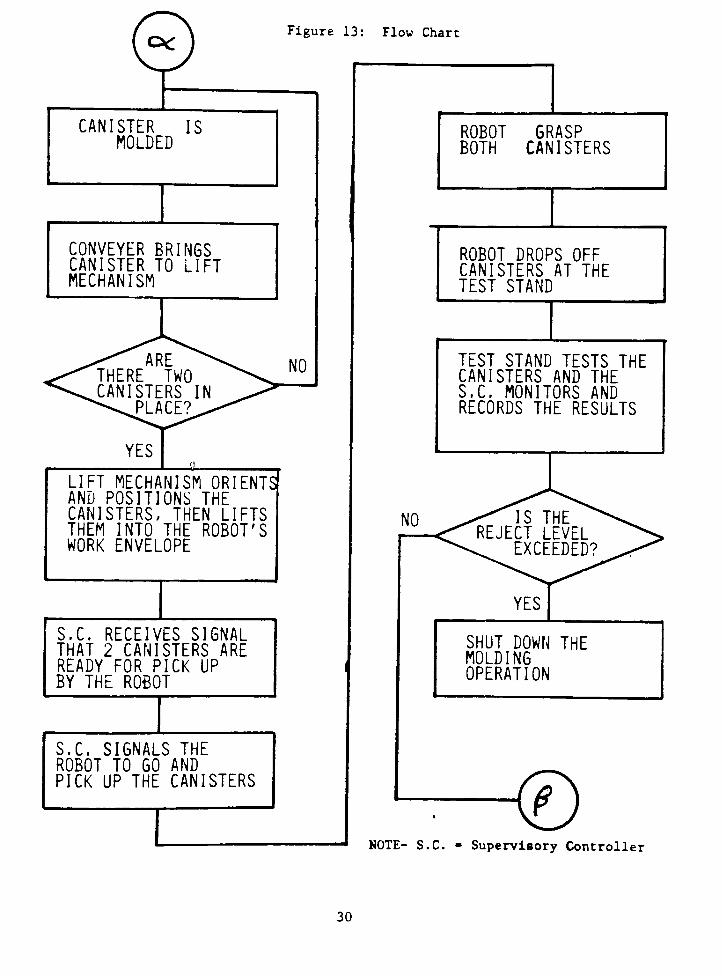
Flow Chart
Discussed here are the steps which the work cell would go
through during all cycles. An explanation is given on the
packing and testing routines, and is followed by a description of
the routines for placing the separator trays and basket
exchanges. A process flow chart (Figure 13) is provided to helpthe reader understand each of the routines. The most logical
place to begin the discussion is as far up stream as possible at
the injection mold machine.
27

After a canister has been molded, the conveyer system brings
it to the canister handling device which positions and orients
it. Shortly thereafter, a second canister will follow suit and
trip a sensor which signals the supervisory controller that two
canisters are in place. The supervisory controller then alerts
the robot to pick up the canisters.
Once the canisters are grasped, the robot places them on
the test stand. Sensors on the test stand then signal the
supervisory controller that the canisters are in place and to
begin testing.
Once the test is complete, the supervisory controller
signals the robot to pick up the canisters and indicate which, if
any, canisters failed. The supervisory controller records the
defect information (how many and what type, Figure 14).
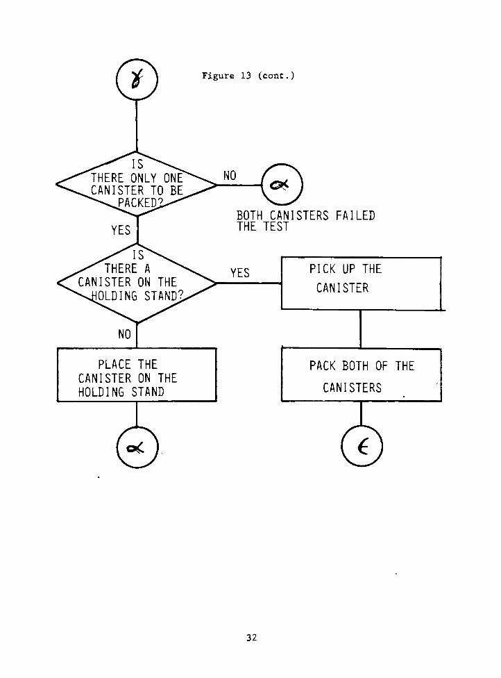
If both canisters passed, the robot packs both canisters.
If one failed and the other passed, the robot will dispose of the
rejected canister and hold onto the good canister-
After disposing of the rejected canister, the robot either
places the good canister onto the holding stand or picks up a
canister which is already there. The supervisory controller
keeps track of the status of the holding stand. The holding stand
was included in this system to ensure that the canisters are
packed in pairs. Trouble arises if the robot packs only one
canister with an end-effector designed to handle the canisters in
pairs as shown in Figure 12. Packing the canister in pairs
greatly simplifies the packing algorithms.
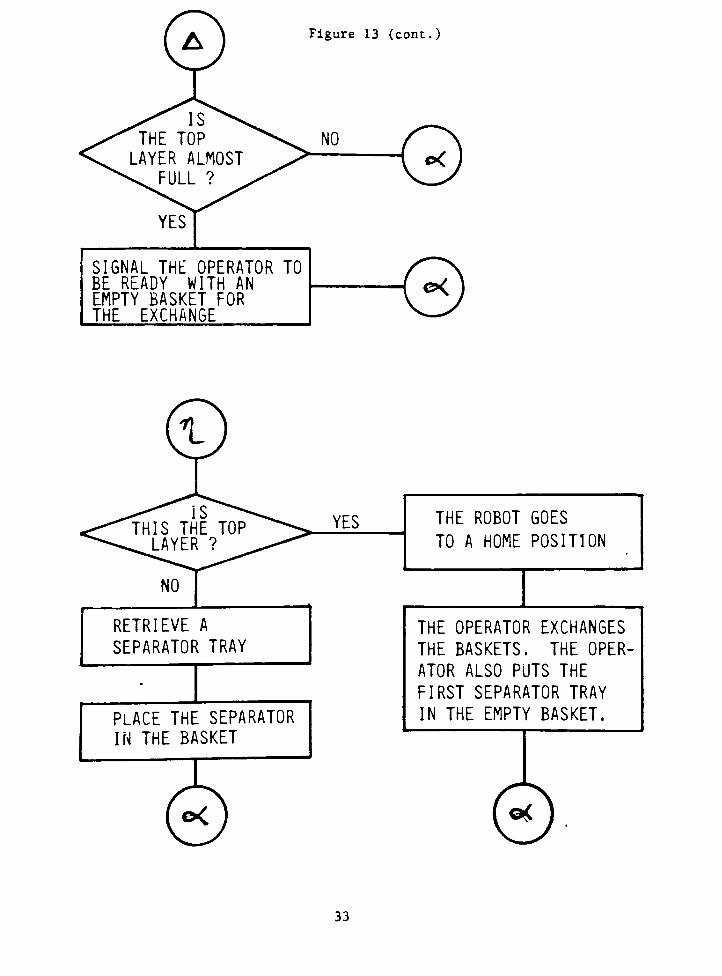
Once a layer is full, the robot needs to retrieve a
separator tray. Since both the robot and the supervisory
controller are keeping count of the number of canisters actually
packed, the supervisory controller knows when the top layer of
the basket is nearly full. At this time, the supervisory
controller signals the operator to be ready with an empty basket
for the exchange.
Since the above process is quite long, a flow chart is
provided to show how the routines interact. The flow chart is
presented in a generic form so that it be adaptable to any
manufacturer's robot controller system(Figure 13).
28

END-EFFECTOR
CANISTERS
COLLISION
AREA
SIDE OF
BASKET
SEPARATOR
TRAY
OF BASKET
Figure 12: Problem of PackingCanisters Singly
29
CKFigure 13: Flow Chart
CANISTER ISMOLDED
CONVEYER BRINGSCANISTER TO LIFTMECHANISM
LIFT MECHANISM ORIENTSAND POSITIONS THECANISTERS, THEN LIFTSTHEM INTO THE ROBOT'SWORK ENVELOPE
ROBOT 6RASP
BOTH CANISTERS
ROBOT DROPS OFFCANISTERS AT THETEST STAND
TEST STAND TESTS THECANISTERS AND THES.C. MONITORS ANDRECORDS THE RESULTS
S.C. RECEIVES SIGNALTHAT 2 CANISTERS ARE
READY FOR PICK UP
BY THE ROBOT
NO
S.C. SIGNALS THE
ROBOT TO GO AND
PICK UP THE CANISTERS
SHUT DOWN THEMOLDINGOPERATION
<DNOTE- S.C. - Supervisory Controller
30
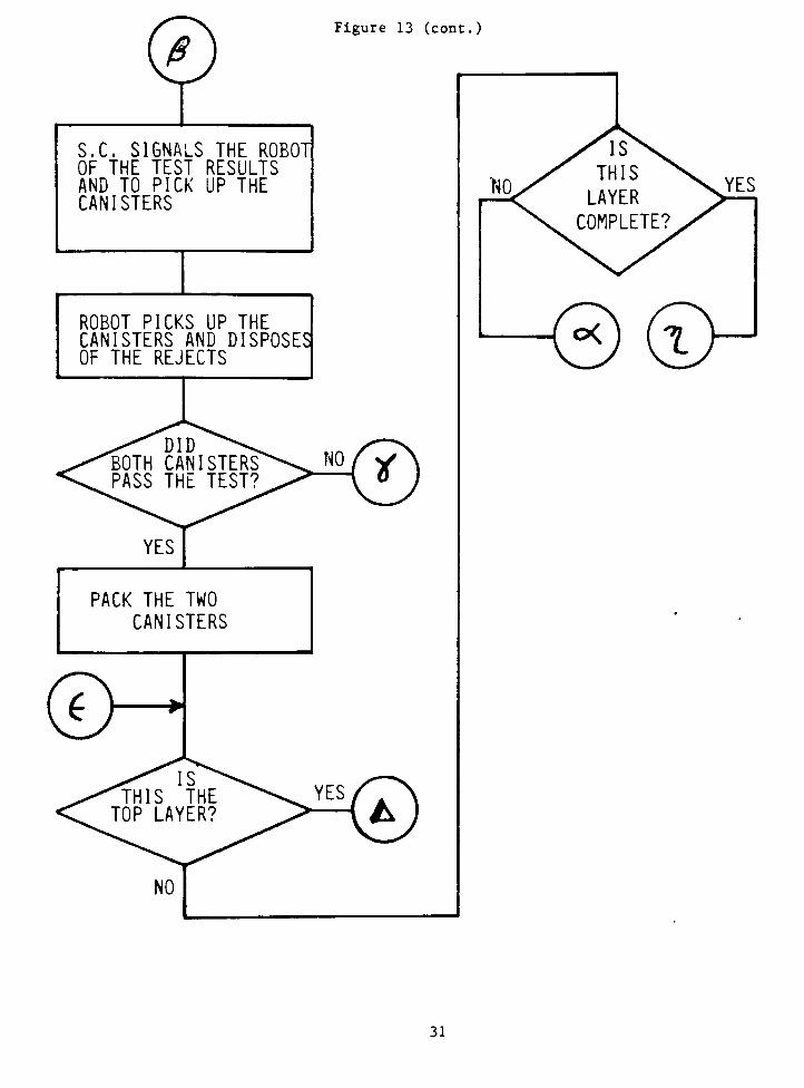
Figure 13 (cont.)
S.C. SIGNALS THE ROBOT
OF THE TEST RESULTSAND TO PICK UP THECANISTERS
ROBOT PICKS UP THECANISTERS AND DISPOSES!OF THE REJECTS
YES
PACK THE TWO
CANISTERS
d>
CvH
31
YES
PLACE THE
CANISTER ON THE
HOLDING STAND
Figure 13 (cont.)
c*
BOTH CANISTERS FAILED
THE TEST
YES PICK UP THE
CANISTER
PACK BOTH OF THE
CANISTERS
32
vAy
Figure 13 (cont.)
Xis\/"THE TOP ^v. NO fV. LAYER ALMOST > ( *^^FULL ? ^^ v_
YES]
SIGNAL THE OPERATOR TOBE READY WITH AN
EMPTY BASKET FOR
THE EXCHANGE
CoK.
)
)
RETRIEVE A
SEPARATOR TRAY
YES
PLACE THE SEPARATOR
IN THE BASKET
THE ROBOT GOES
TO A HOME POSITION
THE OPERATOR EXCHANGES
THE BASKETS. THE OPER
ATOR ALSO PUTS THE
FIRST SEPARATOR TRAY
IN THE EMPTY BASKET.
33

Individual Components Description
To finalize this part of Chapter V, a description of each
major component in the system is given, excluding those already
mentioned. The discussion here includes the canister handling
device, the test stand, the rejection bin, the holding stand, the
basket lifter and the separator trays.
The canister
canister conveyer
conveyer brings the
mechanism. The lif
canisters, and then
Sensors detect when
correctly arranged.
lifting mechanism
canister conveyer -
canister to accumula
handling device has two components, the
and the lifting mechanism. The canister
canister away from the mold to the lift
ting mechanism positions and orients the
lifts them into the robot's work envelope.
two canisters are in the lift mechanism and
A parts buffer is located ahead of the
so that the canisters can accumulate on the
This parts buffer was needed to allow the
te while the baskets are being exchanged.
The test stand tests all of the canisters for two defects,short shot and hole concentricity (Figure 14). Short shot is the
incomplete flow of plastic into the cavity. Hole concentricity
refers to concentricity of the valve stem hole relative to the
seal area on the center component on top of the canister. This
hole must be concentric in order for the canister to operate
correctly. Several methods exist for testing for each of these
defects. The test methodology is beyond the scope of this paper.
Bottom View of
Control Hardware
Inner-Tube
Material
Void
Hole's
TruePosition
ZX73
Control
Hardware
SHORT SHOT DEFECT
Figure 14:
HOLE CONCENTRICITY
DEFECT
Common Injection Molding Defects
34

The basket for holding the rejected canisters is similar to
the basket used for good parts. If the injection mold machine
operated correctly, this bin easily holds a full day of rejected
canisters. To ensure the bin is in the correct position,
mechanical stops are mounted to the floor.
The holding stand is a nest configured to accurately hold
the canister. A limit switch mounted on the stand signals the
supervisory controller that a canister was in place.
If the basket were placed on the floor, the robot would not
be able to reach the bottom. Thus, a lifting mechanism is
required to bring the basket up into the work envelope. The
lifting mechanism must accurately position the basket to ensure
good repeatability and successful loading of the canisters.
35
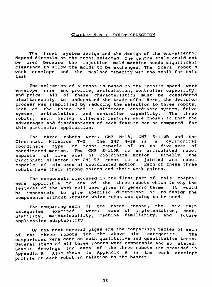
Chapter V.b : ROBOT SELECTION
The final system design and the design of the end-effector
depend directly on the robot selected. The gantry style could not
be used because the injection mold machine needs significant
clearance to allow the molds to be exchanged. The Scara robot's
work envelope and the payload capacity was too small for this
task .
The selection of a robot is based on the robot's speed, work
envelope size and profile, articulation, controller capability,
and price. All of these characteristics must be considered
simultaneously to understand the trade offs. Here, the decision
process was simplified by reducing the selection to three robots.
Each of the three had a different coordinate system, drive
system, articulation, and controller capability. The three
robots, each having different features were chosen so that the
advantages and disadvantages of each feature can be compared for
this particular application.
The three robots were: GMF M-1A, GMF S-110R and the
Cincinnati Milacron T-3 . The GMF M-1A is a cylindrical
coordinate type of robot capable of up to five-axes of
coordinated motion. The GMF S-110R is an articulated robot
capable of five axes of coordinate motion. Finally, the
Cincinnati Milacron (or CM) T3 robot is a jointed arm robot
capable of six axes of coordinated motion. Each of these three
robots have their strong points and their weak points.
The components discussed in the first part of this chapter
were applicable to any of the three robots which is why the
features of the work cell were given in generic terms. It would
be impossible to give specific dimensions or to design the
components without knowing which robot was going to be used.
For comparing each of the three robots, the six main
categories examined were: ease of implementation, cost,
usability, maintainability,machine familiarity, and future
application adaptability.
On the next several pages are the comparison tables of each
of the three robots for the above six categories. The
comparisons were done on both qualitative and quantitative terms.
Several items of all three robots were comparable and so stated.
Layout drawings for each of the three robots are provided in
Appendix A. Also shown in Appendix A is the work envelope
profile of each robot in relation to the basket.
36
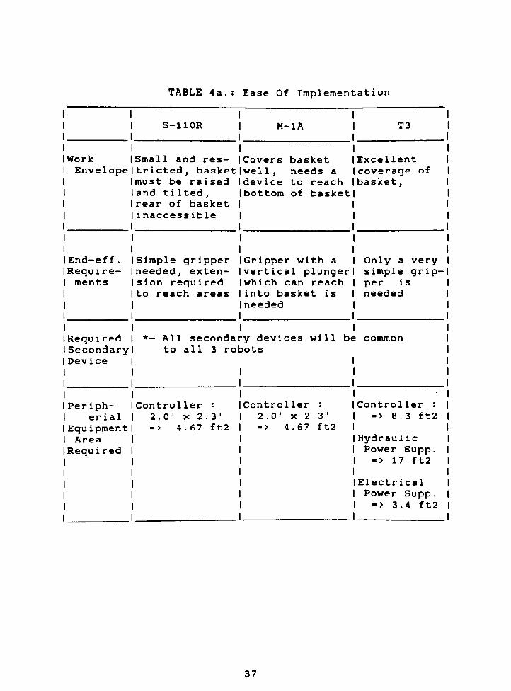
TABLE 4a.: Ease Of Implementation
Work
Envelope
End-eff .
Requi re-
ments
Required
SecondaryDevice
Periph-
er ial
Equipment
Area
Required
S-110R
Small and res
tricted, basket
must be raised
and tilted,rear of basket
inaccessible
Simple gripper
needed, exten
sion required
to reach areas
M-1A
Covers basket
wel 1,
needs a
device to reach
bottom of basket
Gripper with a
vertical plunger
which can reach
into basket is
needed
*- All secondary devices will be
to all 3 robots
Controller :
2.0'
x2.3'
-> 4.67 ft2
Controller :
2.0'
X2.3'
-> 4.67 ft2
T3
Excellent
coverage of
basket,
Only a very
simple grip
per i s
needed
common
Controller :
-> 8.3 ft2
Hydraul ic
Power Supp.
-> 17 ft2
Electrical
Power Supp.
-> 3.4 ft2
37

Table 4b. : Cost
Base |
Robot w/ |
Necessary |
Options 1
End-Eff. |
Cost 1(Rela- 1
tive) 1
S-110R | M-1A
1 $ 66. 8K
$ 47.5K | w/ Extended
1 2-Stroke
1 $ 53. 9K Std.
Simple, | Most Involved,Median Cost 1 Most Costly
T3
98K
Least Invol .
Least Costly
Table 4c: Usability
Ease of
Change
over
Software
Support
Articul
ation
S-110R
Very easy,
Articulation
allows for
simple tools,Large memory
capacity
One palletizing
program avai 1 .
Advanced art
iculation makes
programming
difficult to
understand
M-1A
Easy, May need
a more complic
ated end-ef f .,
Large memory
capacity
Three pallet
izing programs
avai 1 .
Programming is
easy to under
stand since
cyl indrical
coord, robot
T3
Very easy,
Articulation
allows for
simple tools,Available w/
cassette mem.
No palletiz
ing software
avai 1 .
Difficult to
program, too
advanced
articulation
38
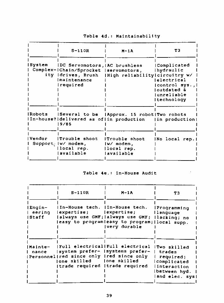
Table 4d.: Maintainability
S-110R M-1A T3 1
System DC Servomotors, AC brushless Complicated 1
Complex Chain/Sprocket servomotors,
hydraulic 1
ity drives, Brush
maintenance
required
High reliabil ity circuitry w/ 1
electrical 1
control sys ., 1
outdated & 1
unreliable 1
technology 1
Robots Several to be Approx. 15 ro bot Two robots 1
In-house? delivered as of
9/85
in production in productionl
Vendor Trouble shoot Trouble shoot No local rep. I
Support^ w/ modem,
local rep.
available
w/ modem,
local rep.
avai Iable
Table 4e In-House Audit
Engin
eering
Staff
Mainte
nance
Personnel
S-110R
In-House tech.
expertise ;
always use GMF;
easy to program
Full electrical
system prefer
red since only
one skilled
trade required
M-1A
In-House tech.
expertise ;
always use GMF;
easy to program;
very durable
Full electrical
systems prefer
red since onlyone skilled
trade required
T3
Programminglanguage
lacking; no
local supp.
Two skilled
trades
required;
complicated
interaction
between hyd .
and elec. sys
39
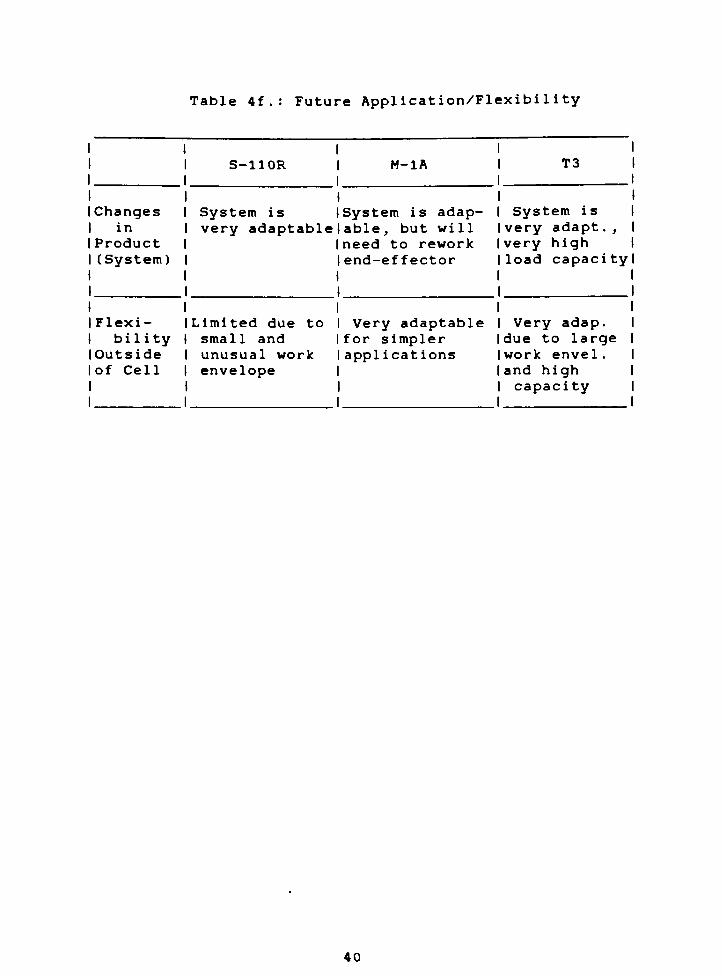
Table 4f . : Future Application/Flexibility
I Changes
in
Product
(System)
Flexi-
bilityI Outside
of Cell
S-110R
System is
very adaptable
Limited due to
small and
unusual work
envelope
M-1A
System is adap-
able, but will
need to rework
end-effector
Very adaptable
for simpler
appl ications
T3
System is
very adapt .,
very high
load capacityl
Very adap.
due to large
work envel .
and high
capacity
40
The Selected Robot
By comparing the information provided in the tables and the
drawings(see Appendix A) for each of the robots, it was decided
that the GMF M-1A robot would be most suitable for this
application. The following are the main features of the GMF M-1A
robot that made it most suitable for this particular application.
- The robot was median in cost
- Preprogrammed palletizing software package
was available.
- The robot had an easy to use control system
and simple work envelope.
- Several of these robots are already in use
at Rochester Products.
- It had the most accurate and reliable drive
system.
- The robot had the necessary wrist
capabilities to ensure the canisters are
packed in a linear fashion.
- The work envelope was well matched to the
basket although a more sophisticatedend-
effector was needed to reach into the
basket .
Now that the robot is selected and the overall layout
derived, enough information is available to design the
end-effector. Chapter VI thoroughly discusses the design of the
end-effector .
41
CHAPTER VI : END-EFFECTOR
The first part of this chapter covers general end-effector
design considerations. The second part of this chapter covers
the design of the end-effector used for this project.
Chapter VI . a : OVERVIEW
The purpose of this OVERVIEW section is to review
end-effector design considerations giving the reader a better
understanding of the features incorporated in this project's
final design. The topics discussed are general considerations,
payload capacity, work envelope considerations, material
selection and maintainability.
General Considerations
A designer should bear in mind that the robot has been
designed in a general manner which ensures that it will be
flexible to handle a variety of tasks. To compensate for this
generality, it is necessary to design the end-effector solely for
a specific application. In other words, design the end-effector
to handle the specific task, such as loading canisters .{ 36} The
designer should be aware that a tremendous amount of time and
effort, put into the design of a robot, can be easily negated bya poorly designed end-ef fector . { 37}
The end-effector should be designed for production use as
opposed to a laboratory application. The end-effector should
be designed and built rugged enough to withstand the industrial
environment . {38}
Many robotic applications exist which require the robot to
do more than one job. If this is the case, the designer needs to
determine if the two tasks are compatible. Secondly, the designer
needs to determine if both tasks can be handled by the same
end-effector. For this project, the end-effector will load the
canister and the separator trays into the basket (explained later
in this chapter) .
Gripping
How the end-effector grips the part is an important
consideration for many robotic applications. First, the designer
should consider all forces exerted on the end-effector. A robot
is dynamic, thus a grasped part will exert a dynamic force on the
gripper while the robot is in motion. As a rule of thumb, the
42
dynamic force is twice the weight of the part. For example, a
1-pound payload will exert approximately 2 pounds of force onto
the end-effector when the robot is in motion. {39}
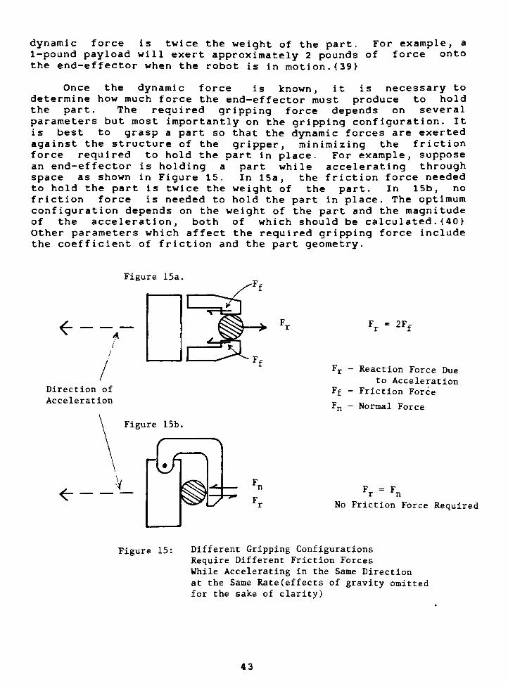
Once the dynamic force is known, it is necessary to
determine how much force the end-effector must produce to hold
the part. The required gripping force depends on several
parameters but most importantly on the gripping configuration. It
is best to grasp a part so that the dynamic forces are exerted
against the structure of the gripper, minimizing the friction
force required to hold the part in place. For example, suppose
an end-effector is holding a part while accelerating through
space as shown in Figure 15. In 15a, the friction force needed
to hold the part is twice the weight of the part. In 15b, no
friction force is needed to hold the part in place. The optimum
configuration depends on the weight of the part and the magnitude
of the acceleration, both of which should be calculated . {40 }
Other parameters which affect the required gripping force include
the coefficient of friction and the part geometry.
Figure 15a.
<e--
Direction of
Acceleration
Fr"
Ff-
F -
2F,
Reaction Force Due
to Acceleration
Friction Force
Normal Force
Figure 15b.
<- - -V" F = Fr n
No Friction Force Required
Figure 15: Different Gripping Configurations
Require Different Friction Forces
While Accelerating in the Same Direction
at the Same Rate (effects of gravity omitted
for the sake of clarity)
43
The necessary normal force can be derived from the
calculated value of the required friction force. Once this force
is known, a check should be done to ensure that the normal force
does not damage the part. When gripping the part with metal
jaws, minor scratches should be acceptable. If not, the gripper
should have soft non-marking pads made from either rubber or
polyurethane . Metal grippers have the advantage over rubber
grippers offering a more positive grip (bite) and higher wear
resistance. {41} The number of parts the end-effector handles
should be considered since it influences the end-effector design.
For example, if the robot will be required to handle a large
number of parts, the designer must be sure that the contact
surfaces are durable. {42}
Gripping cylindrical parts have several advantages. Graspinga part by either the inner-diameter or the outer-diameter offers
good repeatability and adds a compliant quality to the
end-effector. In other words, the grasping action forces the
part to align into the gripper (compliance) and thus the robot
will know exactly where the part is (repeatability). This helps
tremendously in minimizing the complexity of the work cell. {43}
Payload Capacity
The robot's working payload should always be of concern. The
weight of the end-effector decreases the useful payload capacity
of the robot. For example, if a designer is using a robot with a
50 lb. payload capacity, the robot will have difficulty lifting a
30 lb. object if the end-effector weighs 25 lb. The location of
the center of gravity of the end- effector is also important. The
payload capacity of the robot is often given at the face of the
mounting plate where the end-effector attaches to the robot's
wrist. If the center of gravity of the end-effector is displaced
from the mounting plate, exerting a moment on the axes, the robot
may not be able to handle the manufacturer's maximum specified
load. {44}
Work Envelope
The end-effector does not change the shape of the work
envelope, but rather displaces it. This has the greatest impact
on a robotic work cell which is already in place. A new
end-effector may displace the work envelope enough to make
certain areas unattainable, but this displacement may allow the
robot to access areas which it might not have been able to reach
previously. {45}
44
Material Selection
If high durability and strength are of importance, and the
robot has adequate payload capacity, the end-effector should be
made of steel. If weight is the main concern and/or strength is
a lesser concern, aluminum is the best choice. Since aluminum is
not as durable as steel, additional measures need to be taken to
ensure the end-effector will withstand an industrial environment.
Steel threaded insets should be used to prevent the bolts from
stripping the soft aluminum. Interfacing surfaces should be
hardened to minimize wear and deformation. It is a good idea to
use a combination of both steel and aluminum in the end-effector
to exploit the advantageous qualities of each material . {46 }
Maintainability
The ability of the end-effector to be repaired quickly is of
great importance. The longer the work cell is down due to
end-effector repairs, the less productive it becomes. A basic
means of implementing a successful production tool is to
minimize the quantity and the types of fasteners used. Also,critical bolts should not be hidden. Any component(s) which fails
frequently, should be readily accessible and spares should be on
hand. Beyond this, if the robot and end-effector are used in a
critical production area where down time cannot be tolerated, it
is wise to have a spare end-effector on hand. {47}
45

Chapter VI. b : END-EFFECTOR DESIGN FOR PACKING CANISTERS
The main areas of discussion are assessment of the end-
effector task, the robot/end-effector interface, examination of
how the canister will be.gripped,
the gripper design, the
separator tray pick up device, and the compliance device.
Finally, details such as material selection, weight and center of
mass calculations, dynamic force calculations, and general
features are discussed.
Task Assessment
For this application, a dual task end-effector is required.
Its primary purpose is to load the canisters into the basket.
Its secondary purpose is to place the separator trays into the
basket. This dual task end-effector simplifies the design of the
work cell and better utilizes the robot.
Considering the primary task first, the end-effector must
meet the following design requirements. First, it must provide
the required"reach"
capabilities to load the canisters on the
bottom of the basket. Second, the end-effector must be able to
handle two canisters simultaneously- The reason for this relates
to the cycle time constraints and the need to test two canisters
simultaneously (see page 26). Third, the end-effector must be
able to grasp and release each of the two canisters
independently. This feature is necessary in the event that only
one of the two canisters tested is found to be defective. The
end-effector must dispose of the defective canister while holding
onto the other canister.
For the secondary task, placing the separator trays into the
basket, the end-effector must be designed to keep the tray stable
while the robot is moving it to the basket and placing it in. If
the tray is unstable (not firmly grasped) its position relative
to the end-effector may change. If this happens, the tray will
collide with the side of the basket upon placement.
To recap, the end-effector must be able to:
- Pack the canisters on the bottom of the basket
Handle two canisters simultaneously
- Grasp and release each of the two canisters independently-
Keep the separator tray stable while the robot is moving
it
46

Interfacing with the Selected Robot
The selected robot was the GMF M-1A cylindrical coordinate
robot. For this application, the wrist was required to yaw. The
yaw feature is utilized to align the canister pairs with the
parts nest in the separator tray. This is shown in Figure 16a.
The only wrist option which offers the required yaw capability is
the F2 wrist which is shown in Figure 16b.
Next to be considered was how the end-effector would reach
into the basket. The end-effector needs to extend downwards,away from the wrist, in order to place the canisters in the lower
section of the basket. The initial concept was to use an
extension arm to reach down into the basket as shown in Figure
17.
The standard Z-stroke (21.6") of the GMF MIA robot was
inadequate to pack both the top and bottom canisters using the
concept shown in Figure 17. The extended Z-stroke (52.6")
version of the robot cost an addition $10,000 and was not cost
justifiable .
Parts Nest in
Separator Trayltyp.)
t
TOP VIEW
Parts Nest in
^Basket.
Separator Trayltyp. I
^ > /
O-
y^Canisters
v_to be placed
^S Canisters
O O to be placed
in parts
nest
Separator Tray
Pitch-Axis Servo Motor
This robot has no yaw
capability and can not
lineup the canisters with
the parts nest.
This robot has yaw
capability and can lineupthe canisters with the
parts nest.
Yaw-Axis Servo Motor
Figure 16a: Yaw capability utilized to
lineup canisters with the
parts nest
End-Effector Mounting Surface
Figure 16b. F2 Wrist Option For GMF M-1A Robot
47
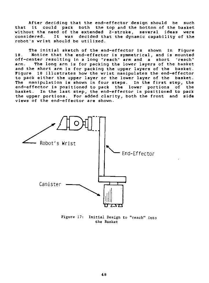
After deciding that the end-effector design should be such
that it could pack both the top and the bottom of the basket
without the need of the extended Z-stroke, several ideas were
considered. It was decided that the dynamic capability of the
robot's wrist should be utilized.
The initial sketch of the end-effector is shown in Figure
18. Notice that the end-effector is symmetrical, and is mounted
off-center resulting in a long"reach"
arm and a short"reach"
arm. The long arm is for packing the lower layers of the basket
and the short arm is for packing the upper layers of the basket.
Figure 18 illustrates how the wrist manipulates the end-effector
to pack either the upper layer or the lower layer of the basket.
The manipulation is shown in four steps. In the first step, the
end-effector is positioned to pack the lower portions of the
basket. In the last step, the end-effector is positioned to pack
the upper portions. For added clarity, both the front and side
views of the end-effector are shown.
UM]Robot's Wrist
Canister
End-Effector
D~Z3T3
Figure 17: Initial Design to"reach"
into
tne Basket
48
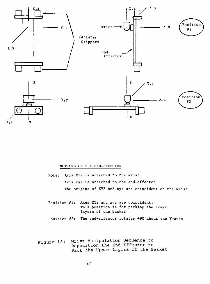
Z,z
/
X,x
Li
aZ> i o/~
IX,z x
Z,z / Y,y
Y,y Wrist >OcCanister
Grippers
Y,y
End-
Effector
OJ
&
Y,y
2tp
X,x
X,z
MOTIONS OF THE END-EFFECTOR
Note: Axis XYZ is attached to the wrist
Axis xyz is attached to the end-effector
The origins of XYZ and xyz are coincident on the wrist
Position #1: Axes XYZ and xyz are coincident;
This position is for packing the lower
layers of the basket
Position #2: The end-effector rotates +90Dabout the Y-axis
Figure 18 Wrist Manipulation Sequence to
Reposition the End-Effector to
Pack the Upper Layers of the Basket
49

10 oa
ip
z
1
y
/
/
1/
/X,x z
FRONT VIEW
X,x
SIDE VIEW
Position #3: The end-effector rotates about
the Z-axis
Position #4: The end-effector rotates about
the Y-axis;
This position is for packing the upper
layers of the basket.
Figure 18: Wrist Manipulation Sequence to Reposition
the End-Effector to Pack the Upper Layers
of the Basket
50
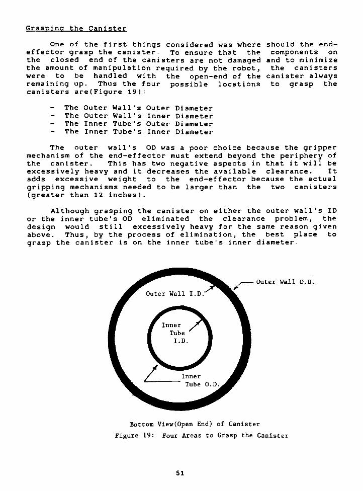
Grasping the Canister
One of the first things considered was where should the end-
effector grasp the canister. To ensure that the components on
the closed end of the canisters are not damaged and to minimize
the amount of manipulation required by the robot, the canisters
were to be handled with the open-end of the canister always
remaining up. Thus the four possible locations to grasp the
canisters are(Figure 19):
The Outer Wall's Outer Diameter
The Outer Wall's Inner Diameter- The Inner Tube's Outer Diameter- The Inner Tube's Inner Diameter
The outer wall's OD was a poor choice because the gripper
mechanism of the end-effector must extend beyond the periphery of
the canister. This has two negative aspects in that it will be
excessively heavy and it decreases the available clearance. It
adds excessive weight to the end-effector because the actual
gripping mechanisms needed to be larger than the two canisters
(greater than 12 inches).
Although grasping the canister on either the outer wall's ID
or the inner tube's OD eliminated the clearance problem, the
design would still excessively heavy for the same reason given
above. Thus, by the process of elimination, the best place to
grasp the canister is on the inner tube's inner diameter-
Outer Wall O.D.
Bottom View(0pen End) of Canister
Figure 19: Four Areas to Grasp the Canister
51
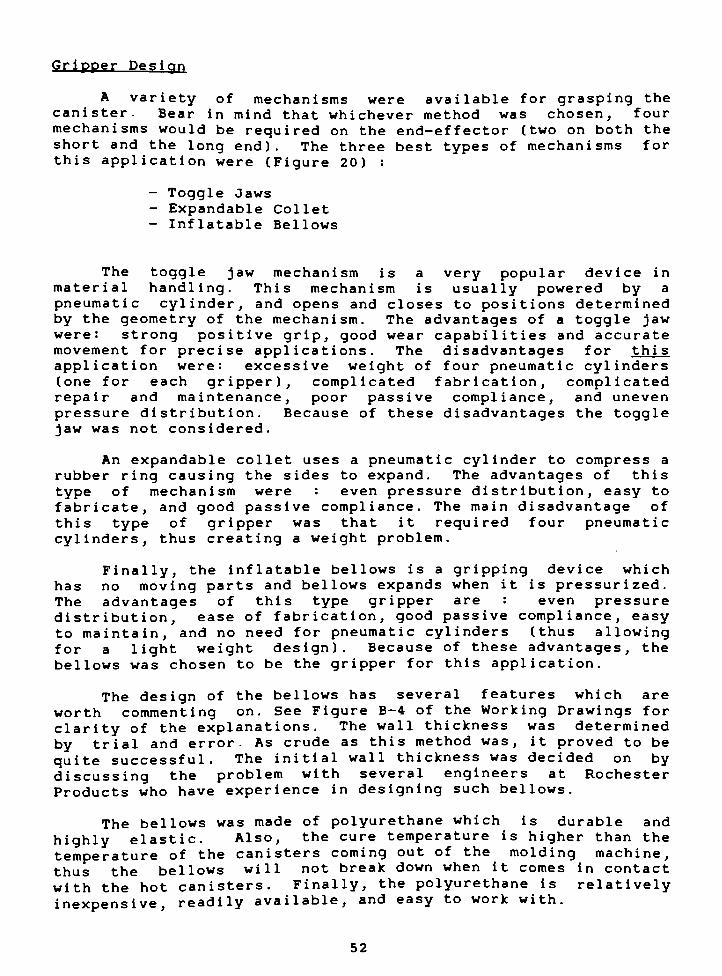
Gripper Design
A variety of mechanisms were available for grasping the
canister- Bear in mind that whichever method was chosen, four
mechanisms would be required on the end-effector (two on both the
short and the long end). The three best types of mechanisms for
this application were (Figure 20) :
- Toggle Jaws
- Expandable Collet
- Inflatable Bellows
The toggle jaw mechanism is a very popular device in
material handling. This mechanism is usually powered by a
pneumatic cylinder, and opens and closes to positions determined
by the geometry of the mechanism. The advantages of a toggle jaw
were: strong positive grip, good wear capabilities and accurate
movement for precise applications. The disadvantages for thi s
application were: excessive weight of four pneumatic cylinders
(one for each gripper), complicated fabrication, complicated
repair and maintenance, poor passive compliance, and uneven
pressure distribution. Because of these disadvantages the toggle
jaw was not considered.
An expandable collet uses a pneumatic cylinder to compress a
rubber ring causing the sides to expand. The advantages of this
type of mechanism were : even pressure distribution, easy to
fabricate, and good passive compliance. The main disadvantage of
this type of gripper was that it required four pneumatic
cylinders, thus creating a weight problem.
Finally, the inflatable bellows is a gripping device which
has no moving parts and bellows expands when it is pressurized.
The advantages of this type gripper are : even pressure
distribution, ease of fabrication, good passive compliance, easy
to maintain, and no need for pneumatic cylinders (thus allowing
for a light weight design). Because of these advantages, the
bellows was chosen to be the gripper for this application.
The design of the bellows has several features which are
worth commenting on. See Figure B-4 of the Working Drawings for
clarity of the explanations. The wall thickness was determined
by trial and error- As crude as this method was, it proved to be
quite successful. The initial wall thickness was decided on by
discussing the problem with several engineers at Rochester
Products who have experience in designing such bellows.
The bellows was made of polyurethane which is durable and
highly elastic. Also, the cure temperature is higher than the
temperature of the canisters coming out of the molding machine,
thus the bellows will not break down when it comes in contact
with the hot canisters. Finally, the polyurethane is relatively
inexpensive, readily available, and easy to work with.
52
The bellows has a long bolt traveling down its center to
prevent the bellows from elongating while it is being inflated.
Without this bolt, the bellows would stretch axially as opposed
to expanding radially as required. The reason for this is that
the hoop stress is approximately twice the longitudinal stress.
Thebellows'
geometry had two "designedin"
passive
compliance features which allow for slight misalignments when the
robot attempts to pick up the canisters. The tip of the bellows
was tapered allowing it to"thread"
the canister if not correctly
positioned. The second taper near the base of the bellows (see
Figure A-4 of Appendix A) assured that the canisters had good
radial and axial repeatability (assuring the canister would
always be in the same place after it has been picked up). Also,the deflated diameter of the bellows is 1/8 inch less than the
inner diameter of the inner tube. This allowed significant
leeway for variation in position and the inner tube's inner
diameter -
Although the canisters are light in weight, they need to be
firmly gripped. The rings on the outside of the bellows (Figure
A-4) allowed for additional gripping firmness. The length of the
bellows was also longer then needed. This was done to ensure the
gripper could grasp a canister which had a severe case of short
shot .
53
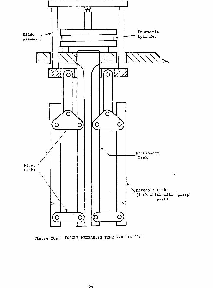
Slide
Assembly
Pivot
Links
Pnuematic
Cylinder
5v
StationaryLink
Moveable Link
(link which will"grasp"
part)
Figure 20a: TOGGLE MECHANISM TYPEEND-EFFECTOR
54
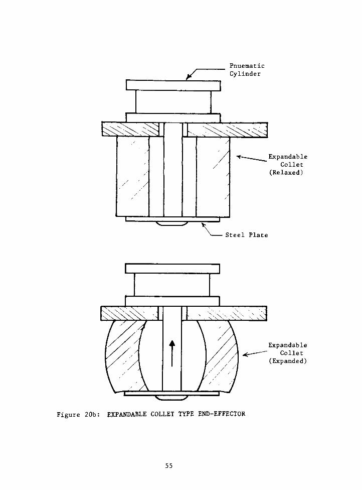
Pnuematic
Cylinder
^c
/
Expandable
Collet
(Relaxed)
Steel Plate
Expandable
Collet
(Expanded)
Figure 20b: EXPANDABLE COLLET TYPE END-EFFECTOR
55
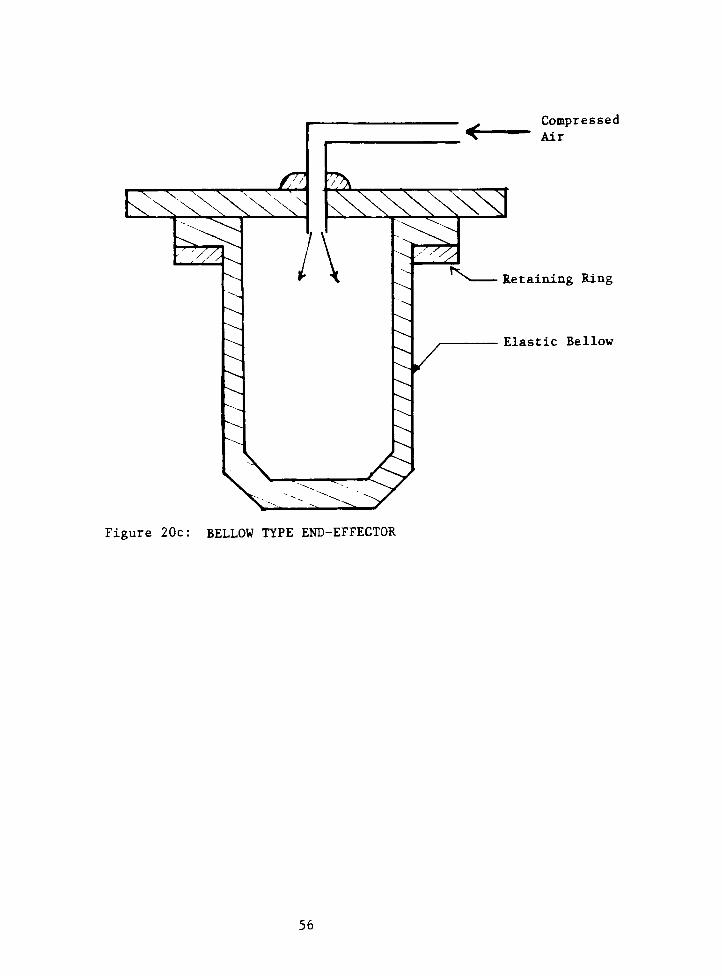
V V-
k r<
V
CL.&
Compressed
K Air
^J
^
/\ ZZiRetaining Ring
Elastic Bellow
Figure 20c: BELLOW TYPE END-EFFECTOR
56
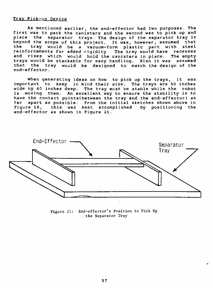
Tray Pick-up Device
As mentioned earli
first was to pack the c
place the separator
beyond the scope of thi
the tray would be
reinforcements for adde
and rises which woul
trays would be stackabl
that the tray would
end-effector .
er, the end-effe
anisters and the
trays. The desigs project. It w
a vacuum-form
d rigidity- The
d hold the cani
e for easy handl
be designed t
ctor had two purposes. The
second was to pick up and
n of the separator tray is
as, however, assumed that
plastic part with steel
tray would have recesses
sters in place. The empty
ing. Also it was assumed
o match the design of the
When generating ideas on how to pick up the trays, it was
important to keep in mind their size. The trays are 50 inches
wide by 40 inches deep. The tray must be stable while the robot
is moving them. An excellent way to ensure the stability is to
have the contact points (between the tray and the end-effector) as
far apart as possible. From the initial sketches shown above in
Figure 18, this was best accomplished by positioning the
end-effector as shown in Figure 21.
End-EffectorSeparator
Tray
Figure 21: End-effector's Position to Pick Upthe Separator Tray
57
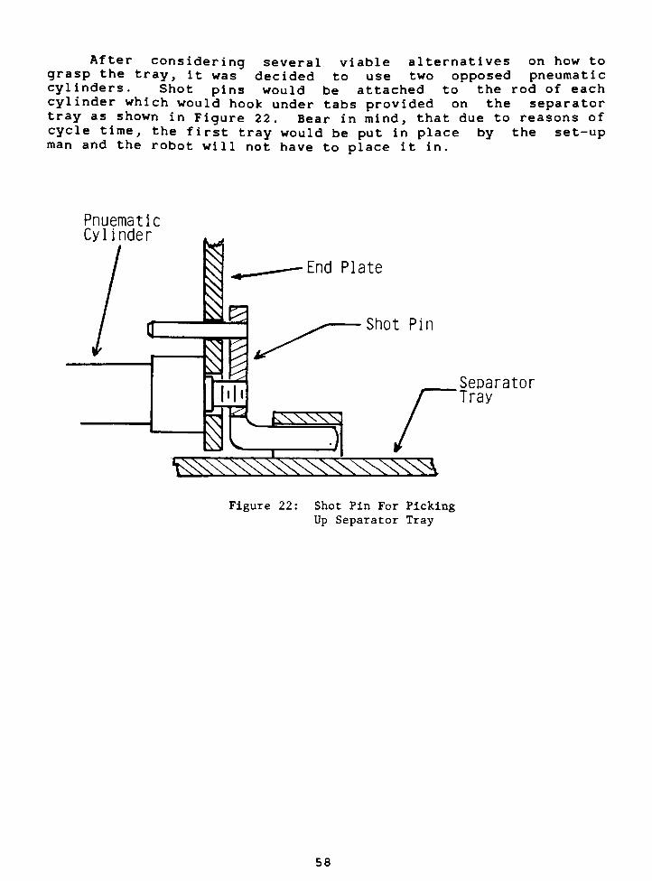
After considering several viable alternatives on how to
grasp the tray, it was decided to use two opposed pneumatic
cylinders. Shot pins would be attached to the rod of each
cylinder which would hook under tabs provided on the separator
tray as shown in Figure 22. Bear in mind, that due to reasons of
cycle time, the first tray would be put in place by the set-upman and the robot will not have to place it in.
PnuematicCylinder
End Plate
Shot Pin
Separator
Tray
v^xx^^xxvvvxxvvvh
Figure 22: Shot Pin For Picking
Up Separator Tray
58
Compliance Devieo
In the event of a collision, a compliance device would
minimize or prevent damage from occurring to either the robot,
the end-effector, or the object which the robot collided with.
Damage to either the robot or the end- effector would be costlyfor two reasons. The first is the cost of repair or replacingthe damaged components. The hidden cost is the loss of
production time.
Not only does the compliance device prevent damage being
imparted, it can also be equipped with microswitches which will
electrically signal the controller that a collision has occurred
and to shut the system down. Thus the compliance device acts as
a time buffer providing the controller extra time to react to the
collision signal.
The compliance device for this application has 6 degrees of
freedom and is self-realigning. That is, if slightly displaced,the compliance device automatically moves back to the correct
position. For good repeatability, the compliance device has no
play under normal use.
Figure B-9 of the working drawings (see appendix B) shows a
cross sectional view of the assembled compliance device. For
reasons of weight, the compliance device is made of aluminum. The
forward plate and centering cones, however, are made of steel,
and the bearing surfaces are polished and hardened. This is done
to minimize friction between the two surfaces (Figure B-8).
Notice how the centering plate and the post can rotate
around, and move parallel to, the center line. This provides two
degrees of freedom. The centering plate can also pivot around
any one of the three centering cones providing two additional
degrees of freedom. Finally, the centering plate can be moved in
the direction normal to the face of the page and vertically
parallel to the face of the page. This provides the last two
degrees of freedom. The combination of these movements allow for
the necessary 6 degrees of freedom.
The force exerted onto the centering plate by the springs
causes the compliance device to realign. The spotfaces on the
back side of the centeringplate and on the front side of the
back plate holds the springs in place. Using the dimensions of
the parts of the compliance device, basic tr igonometer ic
59
calculations were performed to ensure that no binding occurs
during deflection. Ten tapered flat-head screws secured the
compliance device to the robot's wrist, six are used to secure
the adapter plate to the wrist and four to secure the back plate
to the adapter plate.
Materials. Weight and Center of Mass Calculations
The overall dimensions of the end-effector were based on the
task requirements. The separator tray thickness was assumed to
be 1 inch for these calculations. Using the separator tray's
thickness, the height of the canister, the depth of the basket,and the wrist dimension, the necessary end-effector dimensions
were derived. This was done for both the long and short sections
of the end-effector (Appendix C) .
After the initial end-effector design was derived, the
weight and the center of mass were calculated (Appendix D).
These calculations assured the designer that the GMF robot was
able to hold the end-effector in place. The canister weight was
not included because it is quite small compared to the weight of
the end-ef fector -
The weight of the end-effector was 13.1 lb. The maximum
capacity fra the robot, using the F2 wrist, is 40 lb. Thus the
robot has 27 lb. lift capacity. Since a separator tray would not
weigh any more then 10 lb., the robot has plenty of payload
capacity .
It was necessary to know the center of mass of the end-
effector for several reasons. One reason was to find the static
moment that the end-effector exerts on to the wrist. The
resulting moment was found to be 7.0 ft-lbs. The torque capacity
of the wrist is 14.8 ft-lbs which was more than adequate
(Appendix D) .
The center of mass was also used to find the necessary
spring force needed to ensure the compliance device would not
slip while the robot was moving at full speed. It was found that
the each spring needed to exert 120 lb. of force on the
centering plate (Appendix E).
Shown in Figures B-l through B-9 (Appendix B) are the
complete workingdrawings of the final end-effector design. The
selected material for all of the components of the end-effector,
except two were aluminum. Aluminum was chosen because of its
light weight and machinabi 1 ity . Lightening holes were provided
in the extension arm to further reduce the weight. No lightening
holes were added to the end-plates because it was felt that extra
rigidity was of greaterimportance than weight conservation. The
entire end-effector was assembled using tapered flat head screws
which did not allow anymovement between parts.
60
The overall success of the end-effector is discussed in the
Summary of this text (Chapter VII). In Chapter VII, the testing
ice, and theof
ove
the bellows, the testing of the compliance devirail design is discussed.
61
CHAPTER VII: SUMMARY AND CONCLUSION
The objectives of this thesis were to conduct a literature
search to support and guide the development of this project; to
design a robotic work cell layout for the given application; and
to design, build and test the end-effector which would be used
in the work cell.
Although these objectives have been accomplished, much
remains to be done before the cell can be implemented. Manyitems need to be designed and developed, and then the whole
system needs to be integrated and debugged. The following are
items needing further development, but are beyond the scope of
this project : the test stand, the holding stand, the separator
trays, the lifting device for the baskets, the canister handlingdevice to deliver the canisters to the robot, and the controller
system.
The results for this design and development effort, are
listed below.
LITERATURE SEARCH
- The literature search provided useful information
which were incorporated into this project and are
listed below.
System layout
- How to layout the separator tray.
- The process for selecting a robot.
- How to position the components.
- The need for flow chart considerations.
- The need for cycle time considerations.
End-effector
- The need for and design of a compliance device
- The importance of the weight and the center of
mass .
- The use of a dual purpose end-effector.
- The need for a durable and light weight design
- The use of ideas on how to grip cylindrical
parts .
- The use of tapered flat-head machine screws.
SYSTEM LAYOUT
The GMF M-1A robot is capable of reaching all points
of the work cell .
- The collision area between the two robots is
minimized .
62
The test stand and reject basket are adjacent to one
another to minimize the time the robot handles a
rejected canister-
- One reject basket is shared by the two robots.
All of the components in the work cell are
perpendicular to the tangent of the robot's work
envelope.
- Each of the two packing baskets are accessible from
the main aisle allowing them to be quickly exchanged.
END-EFFECTOR DESIGN
- Overal 1 :
Since the end-effector was made of aluminum, it is both
light weight and durable. Durability is very important
since the end-effector will be used in an industrial
environment. The majority of the bolts on the end-
effector are located such that they are easily accessible
which allows for quick change overs. After reviewing the
completed end-effector, the author realized that gussets
should have been used between the end plates and the
extension arm. This would increase the rigidity of the
end-plates .
- Bellows:
After one bellows was successfully molded, it was tested
for rigidity. Using air pressure ranging from 5 to 15
psi, the bellows snugly grasped the canister. To check
if the bellows could withstand a higher pressure, it was
removed from the canister and inflated to 20 psi. The
bellows successfullywithstood this pressure and showed
no visible signs of plastic deformation. Once fully
assembled, it was realized that the mandrel inside the
bellows was not necessary since the bellows itself is
quite rigid. Elimination of the mandrel would reduce cost
but not effect performance.
Compliance Device:
The design of the compliance device was slightly altered
during fabrication. The front plate was made of aluminum
as opposed to steel as called for. Steel bushings were
fabricated and force fitted into the front plate
providing a hard surface for the centering cones to ride
on .
63
Once the compliance device was assembled, it had the
necessary six degrees-of-f reedom. It did not, however,
accurately realign because the bearing surfaces on the
centering cones and the bushings were not polished. The
unpolished surfaces caused excessive frictional forces
which hampered the final centering motions of the
device .
On the next five pages are photographs of the completed
end-effector compliance device and canister. The last photograph
show the canister being grasped by the bellows.
In conclusion the objectives of this thesis were met. A
literature search was conducted to support the design of the
robotics system, and the design and construction of the
end-effector. The author also learned to use Rochester
Products'
CADAM system to develop all of the working drawings for
this project. While working on this project, the writer also
gained a practical knowledge of industrial operations. The final
completion of the project is uncertain. This is due to Rochester
Products's rapidly changing product line. Thus the future of the
canister line is not clear at this time.
64
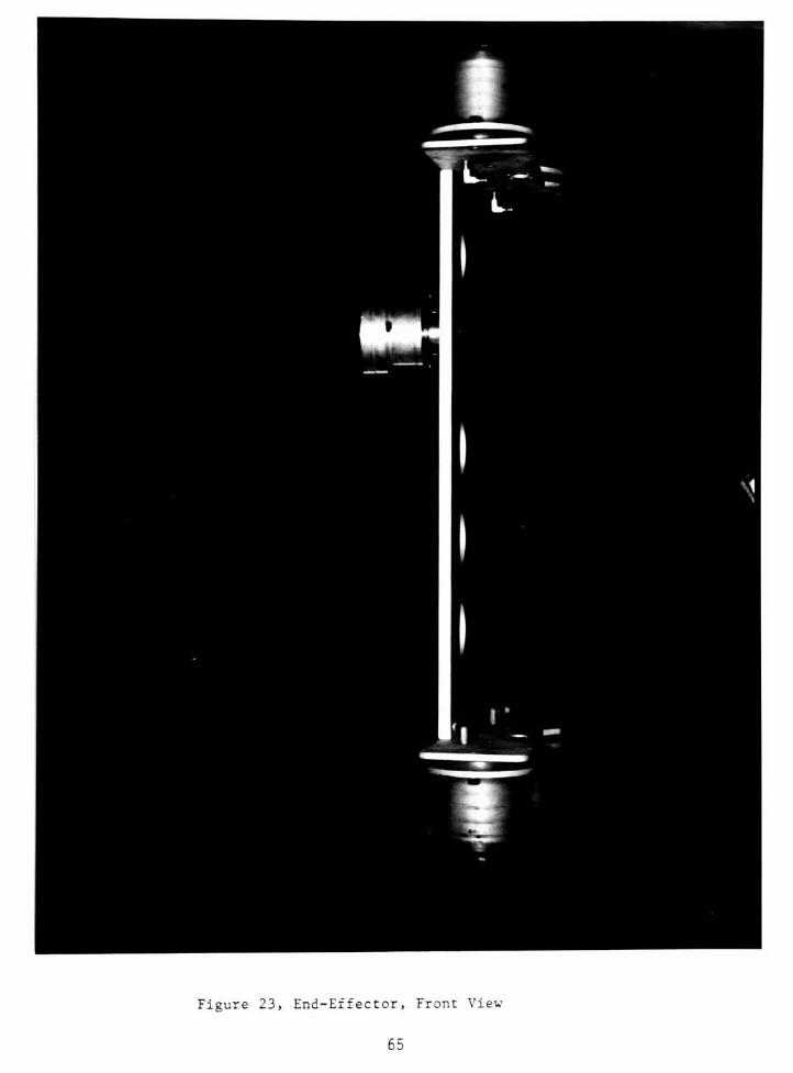
Figure 23, End-Effector, Front View
65
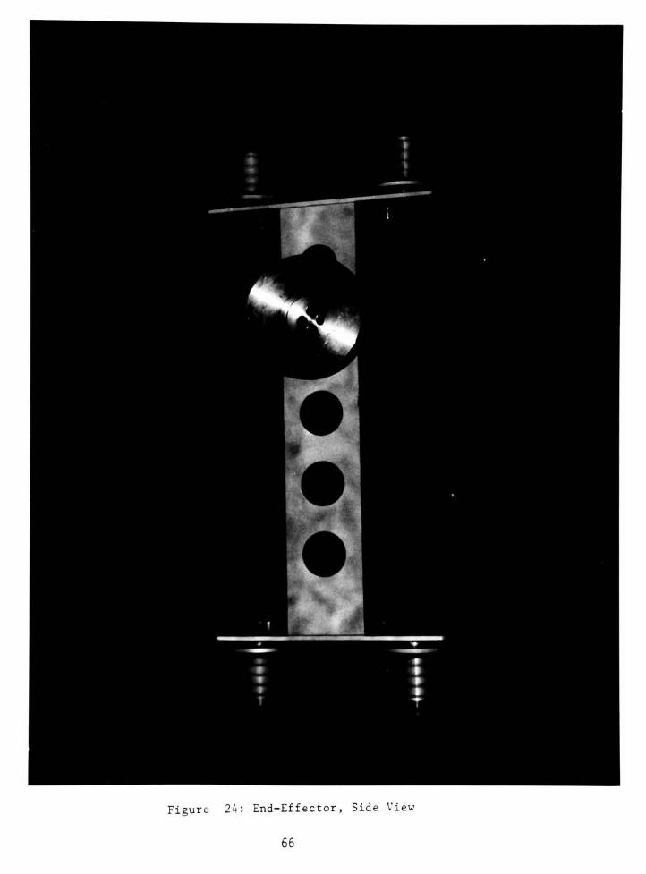
Figure 24: End-Effector, Side View
66
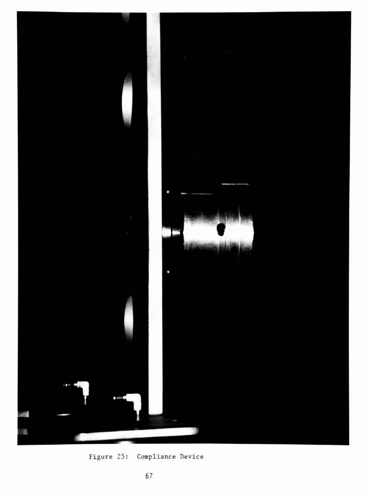
Figure 25: Compliance Device
67

Figure 26:
68
Bellows

Figure 27: Bellow and Canister
69
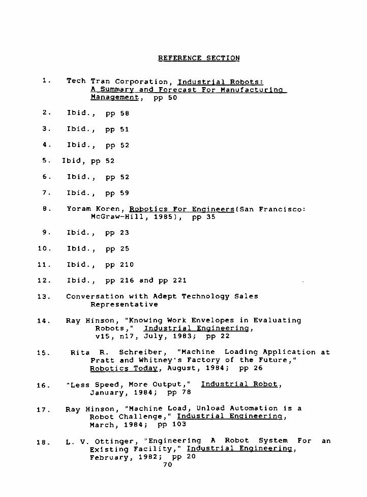
REFERENCE SECTION
1. Tech Tran Corporation, Industrial Robots:
A Summary and Forecast For Manufacturing
Management . pp 50
2. Ibid., pp 58
3. Ibid., pp 51
4 . Ibid .
, pp 52
5. Ibid, pp 52
6. Ibid., pp 52
7. Ibid., pp 59
8. Yoram Koren, Robotics For Engineers(San Francisco:
McGraw-Hill, 1985), pp 35
9. Ibid., pp 23
10. Ibid., pp 25
11. Ibid., pp 210
12. Ibid., pp 216 and pp 221
13. Conversation with Adept Technology Sales
Representative
14. Ray Hinson, "Knowing Work Envelopes in EvaluatingRobots,"
Industrial Engineering.
vl5, nl7, July, 1983; pp 22
15. Rita R. Schreiber, "Machine Loading Application at
Pratt and Whitney's Factory of theFuture,"
Robotics Today. August, 1984; pp 26
16. "Less Speed, MoreOutput,"
Industrial Robot.
January, 1984; pp 78
17. Ray Hinson, "Machine Load, Unload Automation is a
RobotChallenge,"
Industrial Engineering.
March, 1984; pp 103
18. L. V. Ottinger, "Engineering A Robot System For an
ExistingFacility,"
Industrial Engineering,
February, 1982; pp 20
70
19. Ibid., "Less Speed, MoreOutput"
20. Robert N. Stauffer, "Palletizing/Depalletizing :
Robots Makes itEasy,"
Robotics Today.
February, 1984; pp 43
21. Ibid.
22. L. V. Ottinger, "Evaluating Potential Robotics
Applications In A SystemContext,"
Industrial
Engineering, January. 1982; pp 80
23. David W. Abair, "Modern Solution to an Old Fashion
Problem -
Palletizing with an Industrial
Robot,"
Robot 8: Conference Proceedings.
Volume 1, pp 3-29
24. Ibid.
25. Ibid.,Stauffer
26. Ibid., Ottinger, "Engineering A Robot System For an
ExistingFacility,"
27. Ibid. 28. Ibid.
y
29. Ibid., Hinson, "Knowing Work Envelopes in
EvaluatingRobots,"
30. Ibid., Ottinger, "Engineering A Robot System For an
ExistingFacility,"
31. Ibid., Hinson, "Knowing Work Envelopes in
EvaluatingRobots,"
32. Ibid.
33. Ibid., Ottinger, "Engineering A Robot System For an
ExistingFacility,"
34. S. Pike and V. Weatherby, "The Safety Implication
of a NewTechnology,"
Industrial Robot.
September, 1983; pp 185
35. Robert Potter, "Requirements For Developing Safetyin a Robot
System,"
Industrial Engineering
June, 1983; pp 21
36. B. L. Davies, Robotic Technology. pp. 151.
Edited by A. Pugh
71
37. L. V. Ottinger, "Design and Use Considerations For
End-of-ArmTooling,"
Industrial Engineering.
October, 1982; pp 24
38. Ibid. 39. Ibid. 40. Ibid.
41. Rudolph Mutter, "Effective Interfacing ThroughEnd-
Effectors,"
Robots 7: Conference Proceedings.
42. Ibid.
43. Ibid.,Mutter
44. Ibid., Ottinger, "Design and Use Considerations
For End-of-ArmTooling,"
45. Ibid., Ottinger, "Design and Use Considerations
For End-of-ArmTooling,"
46. Rudolph Mutter, "Tailoring the End-Effector to the
Task,"
Robotics Today. January, 1982
47. Ibid., Ottinger, "Design and Use Considerations
For End-of-ArmTooling,"
72

APPENDICIES
Appendix A: Layouts and Work Envelopes For
Selected Robots
B: Working Drawings
C: Sketches of Required Dimensions
D: Weight and Center of Mass Calculations
E: Spring Force Calculations for the
Compliance Device

APPENDIX A
The layouts and work envelopes for the Cincinnati Milacron T3
robot, the GMF S-110R robot and the GMF M-1A robot are shown in
this appendix. The drawings were developed so that the dimensions
of each robot could be compared. The drawings were developed on
Rochester Product's CADAM system and all features are to scale.

7.00 I 8 . 00
28,00
J&-
M
/J
s
3.00
1T
m
\l
LAYOUT FOR THE GMF S- I I OR ROBOT
7.00
/
CDNTR3_^E I
IEI
!a. oo
1
CONTROLLE 1
X"8.00-*
J
NOTE : DIMENSIONS ARE IN FEET
SUPPORT POSTS FIGURE A-l: LAYOUT FOR GMF S-110R ROBOT
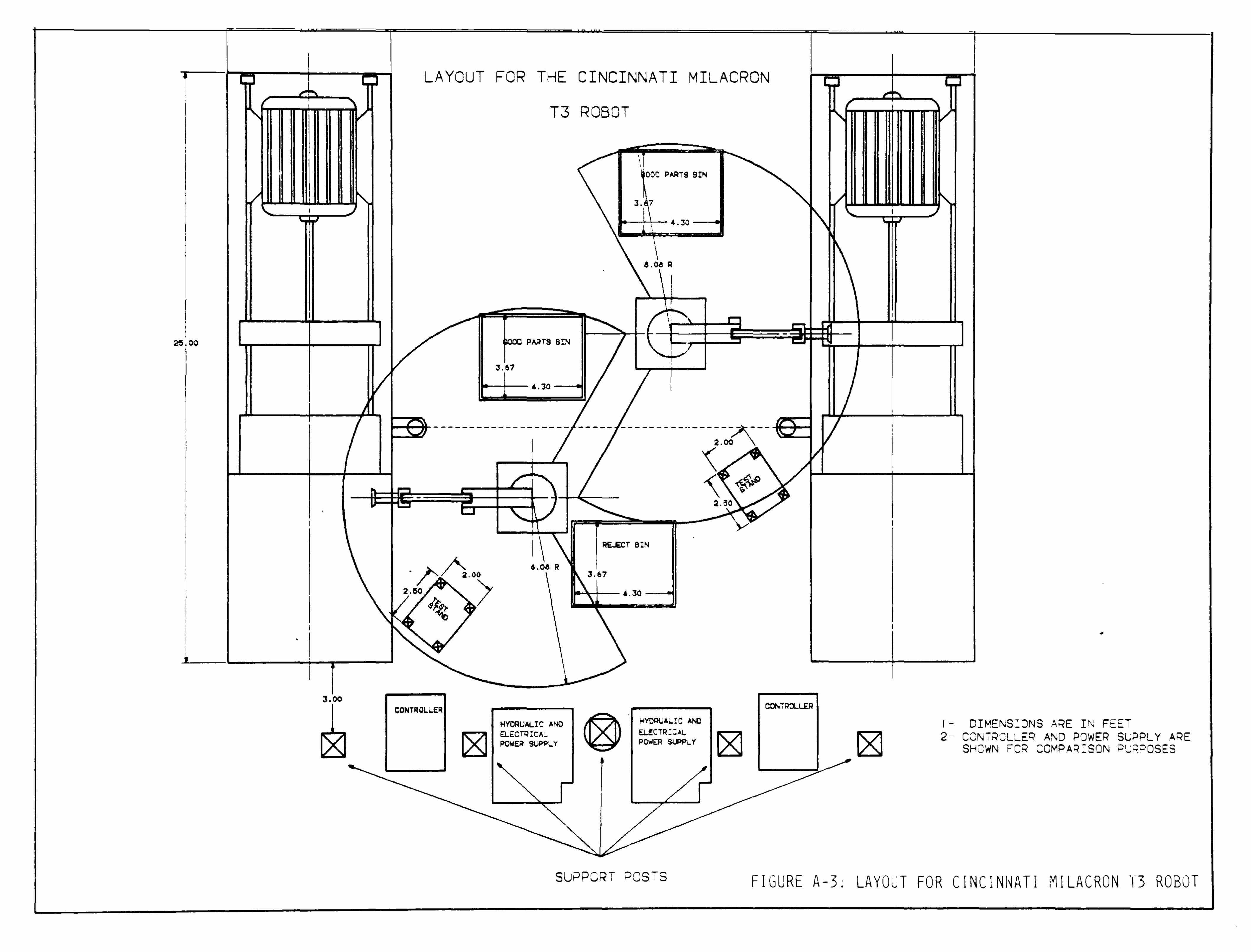
----,.... ----+--~,..,.r-i
I
III
~------~----~-
2e.00
,
•
I
I •
~
3.
~
-2.
LAYOUT FOR THE CINCINNATI MILACRON
T3 ROBOT
i>ARTS SIN
3.",7
_..1-1-1
- 4.30 - .... _ .... '---_ ... a.
PARTS BIN --+-----1
3.67
~+-- 4.30 --4
-------------------i----- - - - -- -- - -~- -- - --- ---2
~
L "" ~'V> . -1- :a.ao
",1\./ ~ I rr ., .
RE ECT eIN
&.0& R 2.00 3.67
-+-- ~. 30 _---0,
CONTROL.L.ER CONTROL.L£R
HYORUALIC ANO EL.~CTRrCAl
!>OWER SUF>PL. Y
HVORUAL.I C AND EL.ECTRIC.l POWER SUPP\..Y
-o---+----"Fi-i
"' /1
-
I
I
1- DIMENS:ONS ARE IN FEET 2- CCN7~CLLEq AND POWER SUPPLY ARE
SHeWN FCR COMPAR:SON PU~~OSES
~
SLJ;JPCRT peSTS FIGURE A-3: LAYOUT FOR CINCINI~ATI MILACRON "1"3 ROBOT
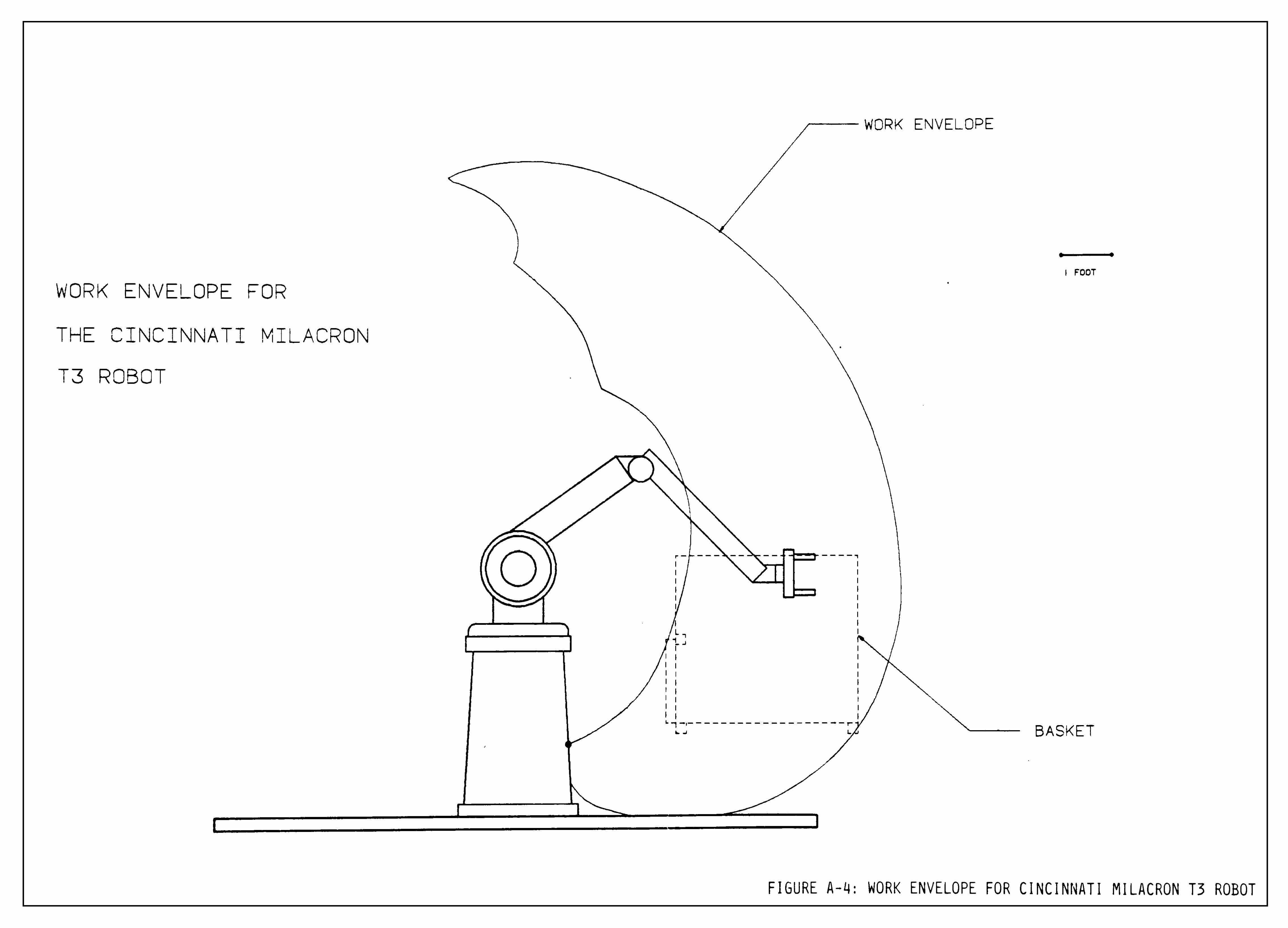
WORK ENVELOPE
WORK ENVELOPE FOR
THE CINCINNATI MILACRON
T3 ROBOT
I FOOT
BASKET
FIGURE A-4: WORK ENVELOPE FOR CINCINNATI MILACRON T3 ROBOT

I
26 00
7.00
jCZL.
18.00
J
3.00
LAYOUT FOR THE GMF M- 1 A ROBOTS SHOWING
POSSIBLE COMPONENET CONFIGURATION
7.00
9WEEP OP THE BACK END Of THE ROBOT
CONTROL I S.OO
CONTROlLE I
2. 00 i
SUPPORT POSTS
S
E
NOTE. DIMENSIONS ARE IN FEET
FIGURE A-5: LAYOUT FOR GMF M-1AROBO"
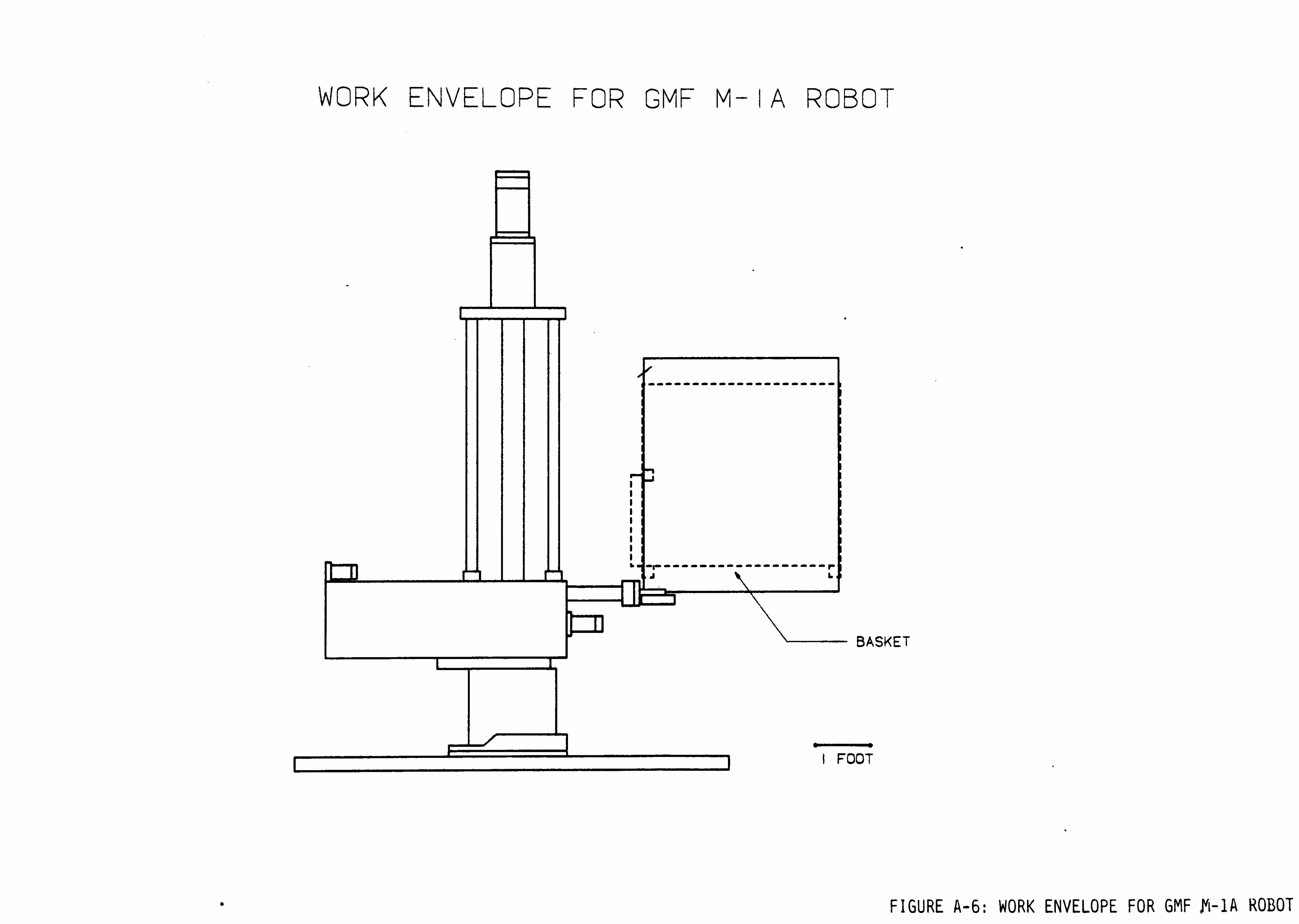
WORK ENVELOPE FOR GMFM- I A ROBOT
BASKET
FOOT
FIGURE A-6: WORK ENVELOPE FOR GMF M-1A ROBOT

n Mia
i n
III Nil
In ni
H II
III
CD
C=
CO
I
EXTENSION ARM
END PLATES
it 11 a
t
n n
", II
11 11
ii, n
11 u
U II
t *
11 n
COMPLIANCE
DEVICE
-MANDREL
BELLOW
HOLD-DOWN RING
END-EFFECTOR ASSEMBLY

ARM EXTENSION. MAT'L . AL
I REQUIRED
-9.19 OIA, 3 HOLES
4.00 t
0.201 DRILL0. 200-20 UNC
4 PLACES
I . 88 OIA
#21(0.1390) DRILL
1.6 DEEP
#10-32 UNF
I.2S DEEP
PLACES
290
FIGURE B-2

end Plates
MAT'L s ALUMINUM
2 REQUIRED
3.500 BOLT CIRCLE DIA
4.00
0.201 DRILL
0.250-20 UNO
2 PLACES
#9(0. 196) DRILL
CSK FOR #10 FH CAP SCR
4 PLACES
T CIRCLE DIA
0.20i DRILL
0.25-20 UNC
6 HOLES
FIGURE B-3

0.38 H0_E
BELLOWS
MAT'L: POLYURETHANE
4 REQUIRED
MOLDED PART
3.75
3.31
2.25
2.75
i t t i i
1. 76
I .25
*
88-J
63
3.50 (50LT CIRClE DIA)
LA.38
FIGURE B-4
3.00 DIA
2.50 DIA
Y
.50DIA
<T\\1:R
.094
I.S7 DIA -
2. 10 DIA
0.25 DIA
1 H0LE9
EQUALLY SPACED
0.063 RAD
4 PLACES
3.00
2.31 DIA -
4.00 DIA
3.13
J 1
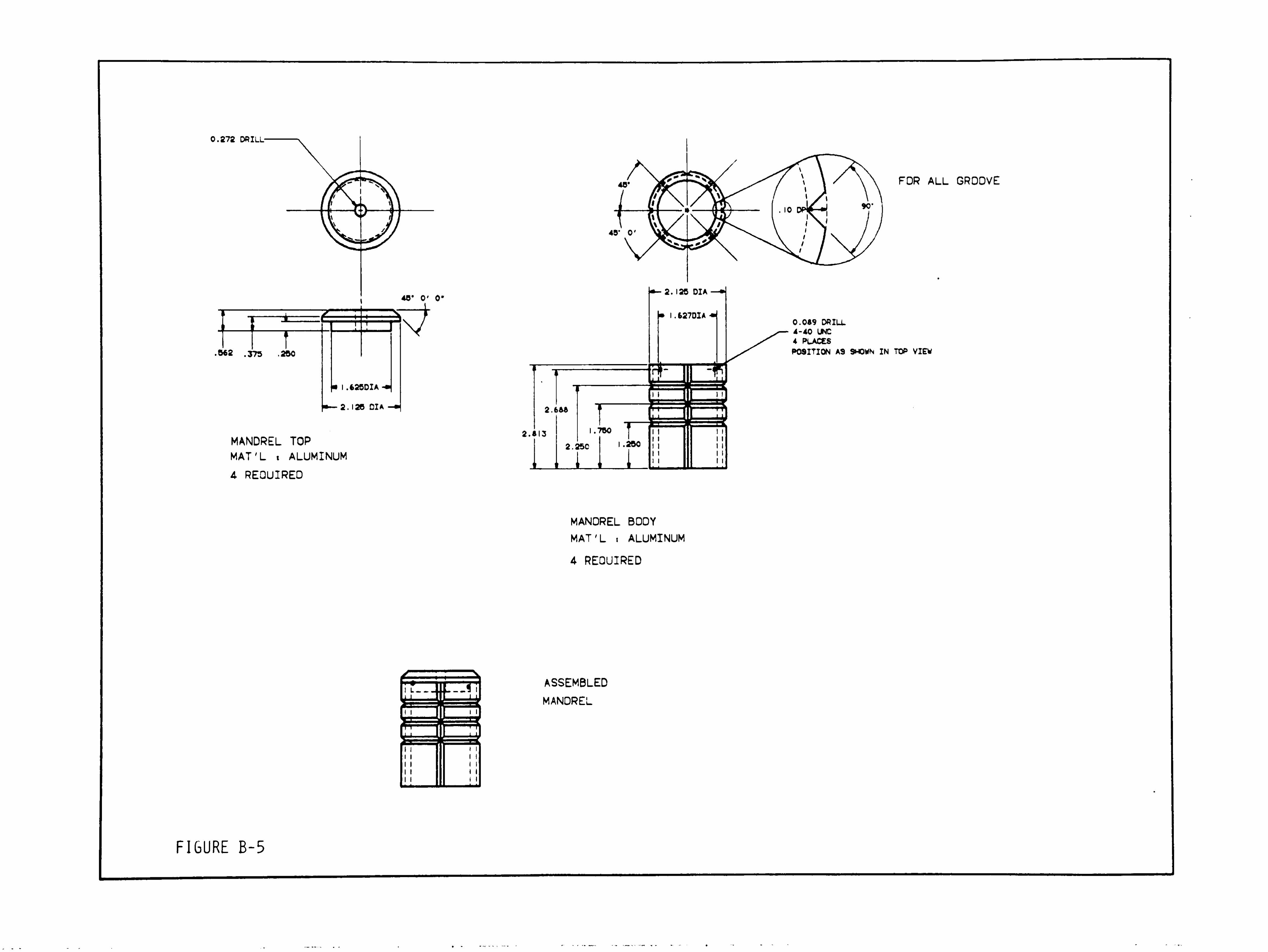
0.272 DRILL
46" 0' 0"
MANDREL TOP
MAT'L i ALUMINUM
4 REQUIRED
2.813
FOR ALL GROOVE
0.089 DRILL
4-40 UNC
4 PLACES
POSITION A9 SHOWN IN TOP VIEW
MANDREL BODY
MAT'L . ALUMINUM
4 REQUIRED
ASSEMBLED
MANDREL
FIGURE B-5

HOLD DOWN PLATE
MAT'L : ALUMINUM
4 REQUIRED
3.050 DIA
0.257 DRILL
EQUALLY SPACED
3.500 BOLT HOLE DIA
,250
i_
T
4.000
i' '
0.089 DRILL
4-40 UNC TAP
-*- 0. 188
2.44
DUNNAGE HOOK
MAT'L : ALUMINUM
2 REQUIRED
2X SCALE
0. 156 R
0.25 DRILL
0.201 DRILL
0.25-20 UNC TAP
0.063 RAD
2 PLACES
FIGURE B-6

CENTERING P^ATE
MAT'L : ALUMINUM
I REQUIRED
0.:260DI*'
0.50 CBORE.0. 125 DEEP
3 PLACES
I .000 DIA
0.257 DRILL
CSK FOR 0.25 FH CAP SCR
POSITION AS SHOWN
SECTION A-A
.250
ng
3.750 DIA
_L
FRONT PLATE
MAT'L : STEEL, CASE HARDEN AFTER MACHINING
I REQUIRED
2.312 DIA
4.800 DIA
.250
0.228 DRILL
CBK FOR *8 FH CAP 9(
4 HOLES
POSITION AS SHOWN
4.362 BOLT HOLE DIA
0.438 DIA
3 HOLES
POSITION AS SHOWN
SECTION A-A
45"
0
3. 125 DIA
^5
0. 123 R
2X SCALE
I .000
I .500 DIA
fifiPf SPACED
125
.625 OIA
:35
1.00 BOLT HOLE DIA
. 125
T
0. 1266
0.1264CIA
POST, I REQUIRED
MAT'L ALUMINUM
CENTERING CONE. HARDEN STEEL
3 REQUIRED

FIGURE B-8

APPENDIX C
Appendix C shows the dimensions of the end-effector in comparison
to the basket, the separator tray and the canister. The dimensions
for the Working Drawings were derived from this sketch.

FIbURE C-lr\
21.6'
I. . I
e
WORK
ENVELOPE
END-EFFECTOR
BASKET
CANISTER
SEPARATOR TRAY
CANISTER
SEPARATOR TRAY
17"
CANISTER
30.0"
SEPARATOR TRAY
CANISTER
^ SEPARATOR TRAY

<M
Q
fa
2
oo
CN
X
a7^
C-2
00
ro
im
-H
3
00
"5K-
V
V
1ce.=r.
o<s:z: i
liJZX
JOO>iq:
LUCOO-
hz^cl.1UJ=Cf
LjJXLlJ
cetluqqO
LLLUQS
uJ3:_jcdCC| rDLOLU O -
=CLl_=nr-|
1 OCOCNJ
/l/_^
ooo
C3-CDCN-
LOrICN
1 1
OJ
Cd
OO
cr:
lo
CO .
| CO
:rco^
=T.LULU
oqh-
'X
LLCOUJ
O
ICQCOI^
arooLU0Q>-
h- LU
LlJOC_> LU
LUt_>
LUZcCLU=a:i
sec: co
( =c
LULUQPQI
CJLU
LU I
c_> -<=r
;z cr_j
t-HCL
COCNQ
Q^-iLU
oo
rsi

APPENDIX D
This appendix contains the necessary sketches and calculations to
determine the weight of the end-effector and the compliance device,
and the location of the center-of-mass for the two. These values
were used to determine if the robot and the robot's wrist had adequate
capacity to handle the end-effector. These values were also used
to determine the spring force required by the compliance device.
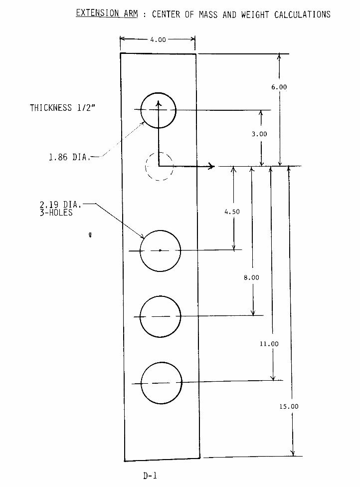
EXTENSION ARM : CENTER OF MASS AND WEIGHT CALCULATIONS
THICKNESS1/2"
1.86DIA.-
2.19 DIA.
3-HOLES
4.00
/
V\
\
6.00
A
3.00
A i< /- J-
4.50
v >
8.00
11.00
_*
15.00
JL
D-l
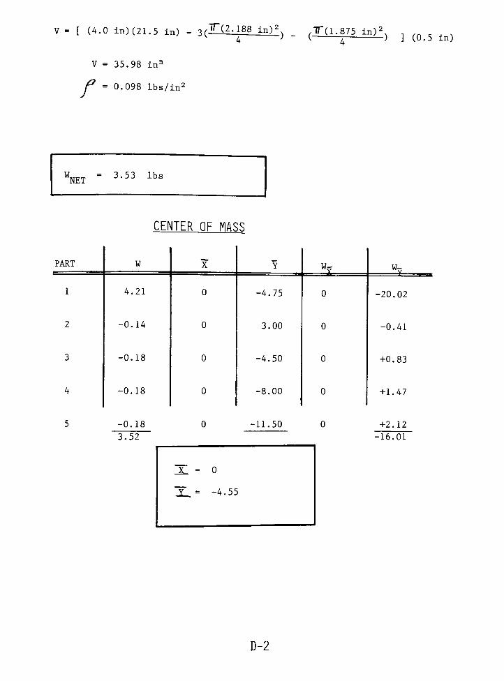
V = [ (4.0 in) (21.5 in) - 3(TQi1188_in)_:
4) -
,T(1.875 in)2..
v 7 ) J (0.5 in)
V = 35.98in3
P = 0.098 lbs/in2
WNET= 3-53 lbs
CENTER OF MASS
-0.18
3.52
-11.50
JL = 0
T =-4.55
PART W X Y "v w-
1 4.21 0 -4.75 0 -20.02
2 -0.14 0 3.00 0 -0.41
3 -0.18 0 -4.50 0 +0.83
4 -0.18 0 -8.00 0 +1.47
+2.12
-16.01
D-2
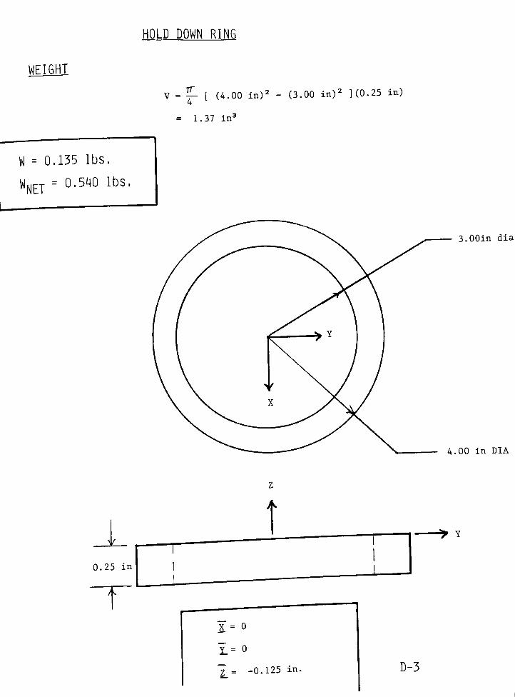
HOLD DOWN RING
WEIGHT
TT
= 1.37in3
V = ?- [ (4.00in)2
- (3.00in)2 ](0.25 in)
4
W = 0.135 lbs.
WNET= 0,54 lbS'
3.00in dia
4.00 in DIA

BELLOWS
APPROXIMATE SHAPE
I*-
i ;.
7
P = 60 lbs./ft3
= 0.0347 lbs./in3
3.00
>L
4.00 DIA-
2.75
lL
-
2.125\>|
I
N 2.625 -^
WEIGHT
w =J (2.625
in)2
(3>0() in)(00347 lbs./in3)1 4
= 0.470 lbs
w =
7T(4.00in.)2
{05Q in-) (0.0347 lbs/ln3)2 4
= 0.218 lbs
_
TT (2.13in)2
5 in) (o.o347 lbs/in3)3 4
-0.338
Jr-1/2
T
W = 0.3491 lbs
W m
= 1.40 lbsNET
D-4
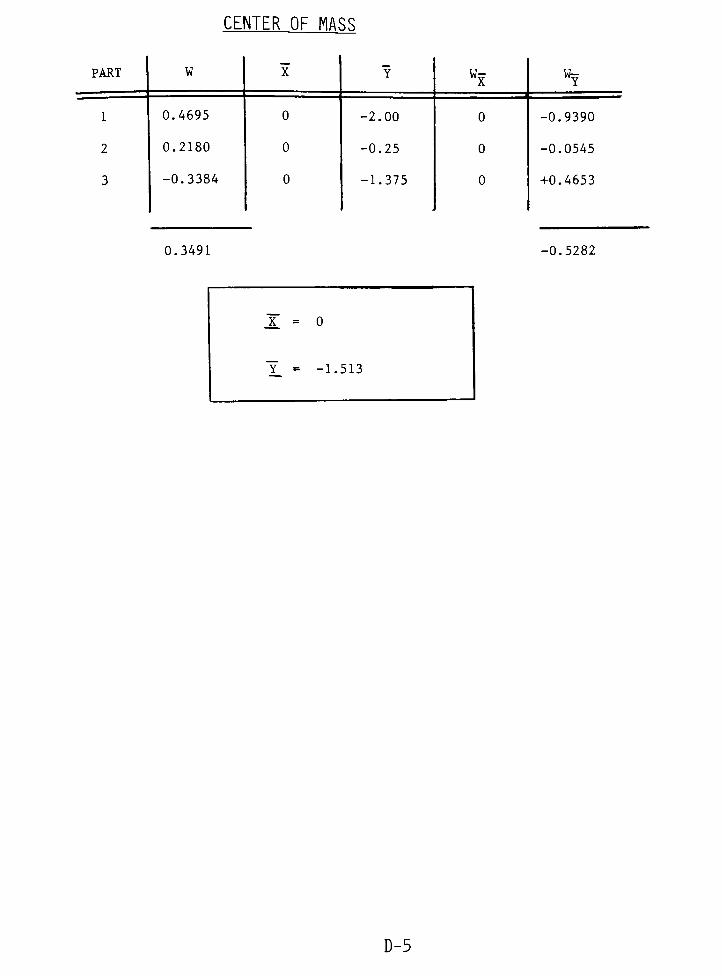
CENTER OF MASS
PART W X Ywx
w-
1 0.4695 0 -2.00 0 -0.9390
2 0.2180 0 -0.25 0 -0.0545
3 -0.3384 0 -1.375 0 +0.4653
0.3491 -0.5282
X = 0
Y =-1.513
D-5
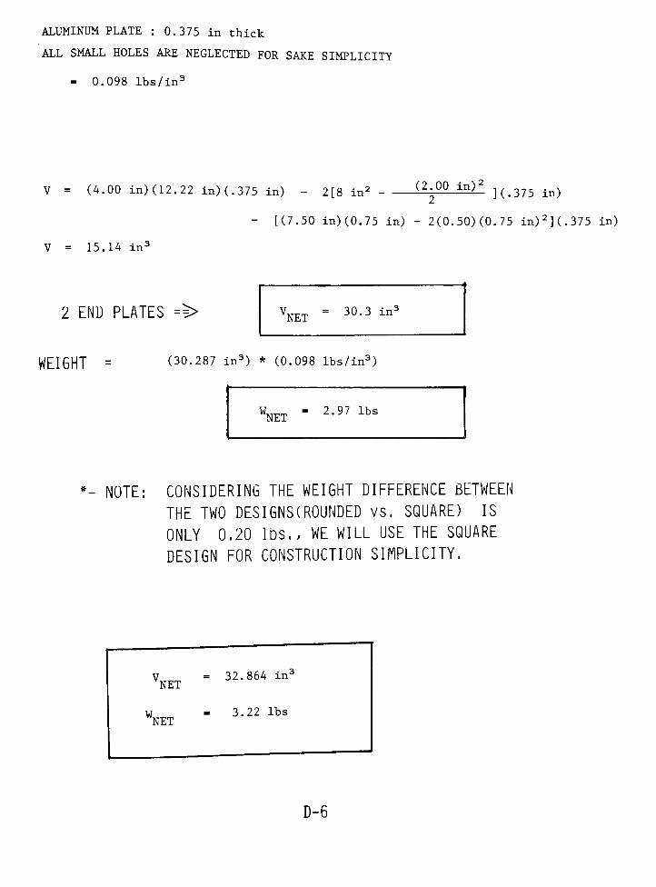
ALUMINUM PLATE : 0.375 in thick
ALL SMALL HOLES ARE NEGLECTED FOR SAKE SIMPLICITY
= 0.098lbs/in3
V = (4.00 in) (12.22 in) (.375 in) - 2[8in2
(2^00 in)*
](.375 in)
- [(7.50 in) (0.75 in) - 2(0.50)(0.75 in)2](.375 in)
V = 15.14in3
2 END PLATES ==> VNT =30.3in3
WEIGHT = (30.287 in3) * (0.098 lbs/in3)
WNET= 2'97 lbs
*- NOTE: CONSIDERING THE WEIGHT DIFFERENCE BETWEEN
THE TWO DESIGNS(ROUNDED vs. SQUARE) IS
ONLY 0.20 lbs., WE WILL USE THE SQUARE
DESIGN FOR CONSTRUCTION SIMPLICITY.
V = 32.864in;
NET
W = 3.22 lbs
NET
D-6
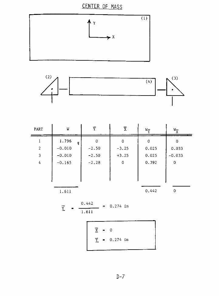
CENTER OF MASS
PART W Y XWY wx
1 1.796g
0 0 0 0
2 -O.OIO -2.50 -3.25 0.025 0.033
3 -0.010 -2.50 +3.25 0.025 -0.033
4 -0.165 -2.28 0 0.392 0
1.611 0.442
0.442
1.611
= 0.274 in
X
Y
= 0
= 0.274 in
D-7

MNDRAL : WEIGHT AND CENTER OF MASS CALCULATION
^ 1.607
NOTE: APPROXIMATE SIZE
WEIGHTv =
(2.125in):
(3.20 in) -
(1.60in):
(3.00 in)
V = 5 32 in3
W = 0 52 lbs
WNET:= 2 08 lbs.
CENTER OF MASS
0.5211
PART W X Y wx WY
1 1.1122 0 -1.60 0 -1.7795
2 -0.5911 0 -1.50 0 +0.8867
J = o
_T
= -1.71
-0.8928
D-8

PICK-UP HOOK : WEIGHT AND CENTER OF MASS CALCULATIONS
PNUEMATIC CYLINDERS APPROXIMATELY 1 lbs.
CENTER OF MASS IS AT GEOMETRIC CENTER OF CYLINDER
MATERIAL : STEEL/
= 0.286lbs/in3
= (1/2 in) (3/8 in)(l 11/16 in)-
(1.M ln)2] (3/8 in)
+ [(1 5/8 in) (3/8 in) + (5/16 in) (3/8 in)] (3/8 in)
V = 0.55in;
WEIGHT WNET" '32 lbS'
2 PARTS
-A 3/8
5/16
4
0.844
1 11/16
w
1 0.091
2 0.013
3 0.068
0.171
r.FNTFR OF MASS
J-3/8
T
0
0
1.0313
0
-1
-1.34
x
0
0
0.070
0.070
JC = 0.410
Y = -0.607
W-
0
-0.013
-0.092
-0.104
D-9

I I
2 C
Q
O1
o
o
->Y
u
u
I I
I 1
->x
13 i=3
~1 97 CI
1
8
3 L
10
1 r
1412
15 D
D-10
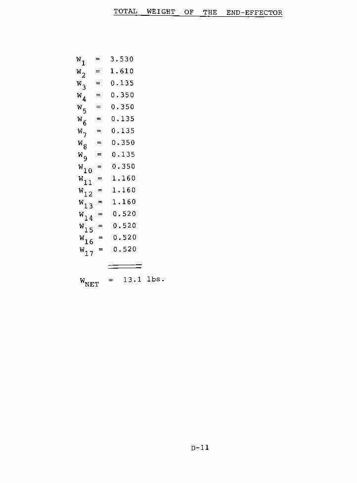
TOTAL WEIGHT OF THE END-EFFECTOR
wl= 3.530
w2= 1.610
W3= 0.135
W4= 0.350
W5= 0.350
W6= 0.135
W7= 0.135
W8
= 0.350
W9
= 0.135
WW10
= 0.350
WWll
= 1.160
W12= 1.160
W13= 1.160
WW14
= 0.520
WW15
= 0.520
W16= 0.520
W170.520
W = 13.1 lbsWNET
D-H

END-EFFECTOR'S CENTER-OF-MASS
PART W W w w
1
2
3
4
5
6
7
8
9
10
11
12
13
14
15
16
17
3.530
1.610
0.135
0.350
0.350
0.135
0.135
0.350
0.135
0.350
1.160
1.160
1.610
0.520
0.520
0.520
0.520
13.09
0.0
1.476
1.750
1.750
1.750
1.750
1.750
1.750
1.750
1.750
2.625
2.625
1.476
1.750
1.750
1.750
1.750
0.0
0.0
-4.110
-4.110
4.110
4.110
-4.110
-4.110
4.110
4.110
0.0
0.0
0.0
-4.110
4.110
-4.110
4.110
-4.550
6.188
6.813
7.888
7.888
6.813
-16.313
-17.388
-16.313
-17.388
8.000
-17.500
-15.688
-17.585
-17.585
8.085
8.085
0.0
2.376
0.236
0.613
0.613
0.236
0.263
0.613
0.236
0.613
3.045
3.045
2.376
0.910
0.910
0.910
0.910
17.878
0.0
0.0
-0.555
-1.439
1.439
0.555
-0.555
-1.439
0.555
1.439
0.0
0.0
0.0
0.0
2.137
-2.137
2.137
0.0
-8.080
9.962
0.920
2.758
2.758
0.920
-2.202
-6.086
-2.202
-6.086
9.280
-20.300
-25.257
-9.144
-9.144
4.204
4.204
-53.496
X = 1.37 in.
Y = 0.0
Z = -4.09 in
D-12

JfflENT EXERTED ON THF RnRnT'.s WRIST
th
\&
2.80$
4.09
SJ
5.50-v>
< 6.42 >
NET MOMENT EXTERTED BY THE END-EFFECTOR ONTO THE
F2 WRIST :
M = (6.42in.)13.09 lbs.
M = 7.0 Ft-lbs
D-13
APPENDIX E
This appendix contains the calculations necessary to determine
the required spring force needed to keep the compliance device in
place while the robot is moving it. Three modes of displacement
were considered. These were slippage, lifting, and rotation(see
FIGURE E-l). Since modes I and III are similar only modes II and
III were considered. The maximum dynamic loading situation occurs
when the end-effector's center of mass is below the compliance
device's centerline, the robot's arm is fully extended and it is
rotating about the Z-axis at the maximum angular velocity. The
minimum spring force required to keep the compliance device stationary
while undergoing maximum dynamic loading is 120 lbs. per spring
(see page E-7) -
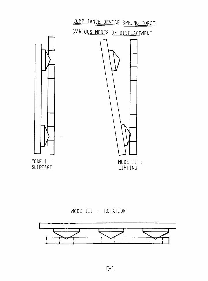
L1ANCE^DEVICE SPRING FORC.F
VARIOUSJMES OF DISPLACFMFNT
MODE I :
SLIPPAGE
MODE II
LIFTING
MODE III : ROTATION
*rrrK7"
1̂ L
E-l
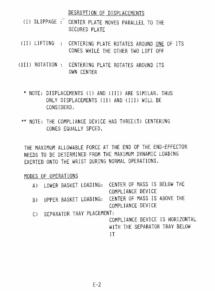
DESRIPTIQN OF DISPLACEMENTS
(I) SLIPPAGE : CENTER PLATE MOVES PARALLEL TO THE
SECURED PLATE
(II) LIFTING : CENTERING PLATE ROTATES AROUND ONE OF ITS
CONES WHILE THE OTHER TWO LIFT OFF
(III) ROTATION : CENTERING PLATE ROTATES AROUND ITS
OWN CENTER
*NOTE: DISPLACEMENTS (I) AND (III) ARE SIMILAR, THUS
ONLY DISPLACEMENTS ( 1 1 ) AND (II I ) WILL BE
CONSIDERD.
**
NOTE: THE COMPLIANCE DEVICE HAS THREE(3) CENTERING
CONES EQUALLY SPCED.
THE MAXIMUM ALLOWABLE FORCE AT THE END OF THE END-EFFECTOR
NEEDS TO BE DETERMINED FROM THE MAXIMUM DYNAMIC LOADING
EXERTED ONTO THE WRIST DURING NORMAL OPERATIONS.
MODES OF OPERATIONS
A) LOWER BASKET LOADING: CENTER OF MASS IS BELOW THE
COMPLIANCE DEVICE
B) UPPER BASKET LOADING: CENTER OF MASS IS ABOVE THE
COMPLIANCE DEVICE
C) SEPARATOR TRAY PLACEMENT:
COMPLIANCE DEVICE IS HORIZONTAL
WITH THE SEPARATOR TRAY BELOW
IT
E-2

MAXIMUM DYNAMIC LOAMNfi.9TTiiflTTnN
GMF M-1A CYLINDRICAL COORDINATE ROBOT
MAXIMUM ROTATIONAL SPEED:
R =72.2"
&= 60 DEG./s. = T/3 RAD/S
AN= R02 (72.2") ( /3 RAD/S)2
= 79.2 in/s2
~A
t orrS ~*
$ i_
DYNAMIC AND STATIC FORCES ON A DUE
TO THE END-EFFECTOR ONLY:
f)
FcmV F
Mw> *
r rcm
W = 13.09 lbs
Mw= 27,75 lb-ln
Fcm- 32.2 lbs
% 132 lb"ln
E-3
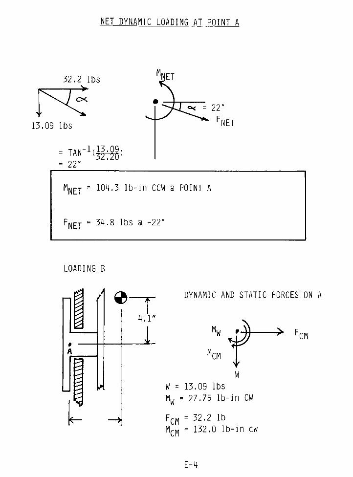
NET DYNAMIC LOADING AT POINT A
'NET
13.09 lbs
IAN (377ZU}
=22
MNET= 104.3 lb-in CCW a POINT A
FNET= 34,8 lbs a
LOADING B
A 9-
A
4.1"
DYNAMIC AND STATIC FORCES ON A
1CM#
-> FCM
Y
W
W = 13.09 lbs
Mw= 27.75 lb-in CW
FCM= 32.2 lb
'CM132.0 lb-in cw
E-4
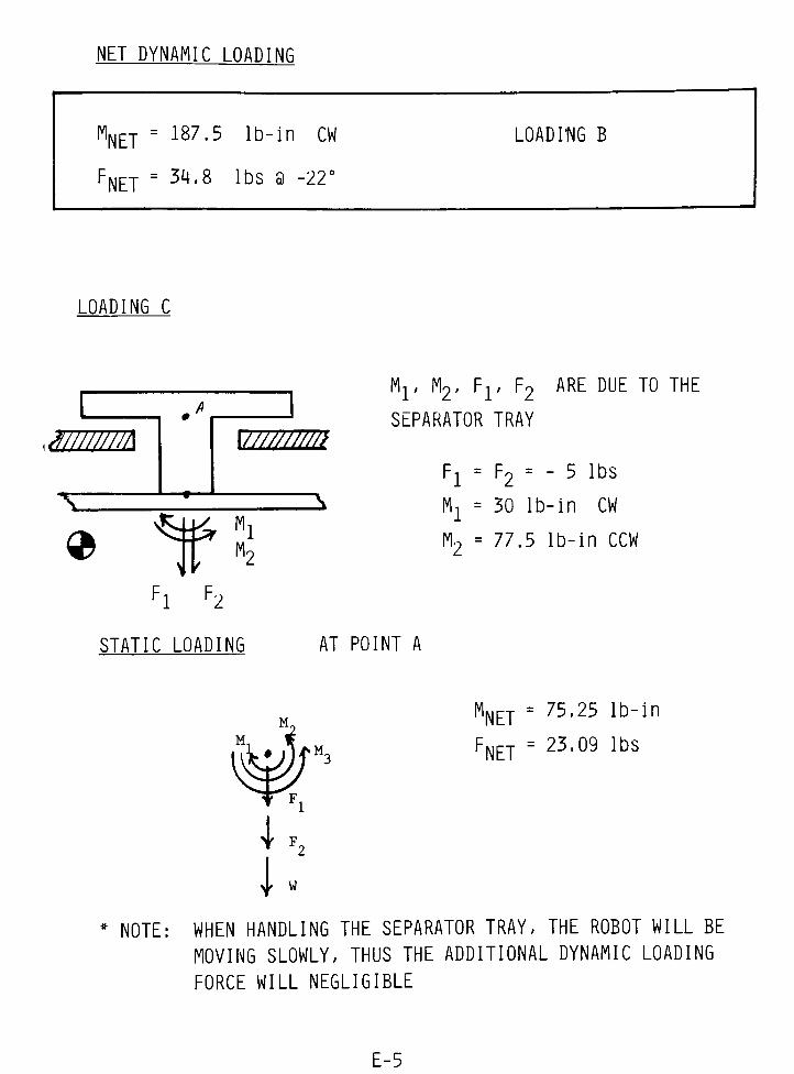
NET DYNAMIC LOADING
MNET
'NET
= 187.5 lb-in CW
= 34.8 lbs a
LOADING B
LOADING C
.mrnm
X
vtw/m
^kfr Ml
Fl F2
2k
Mr M2, Fr F2 ARE DUE TO THE
SEPARATOR TRAY
F2=
F2= - 5 lbs
Mx= 30 lb-in CW
M2= 77.5 lb-in CCW
STATIC LOADING AT POINT A
MNET= 75.25 lb-in
FNET= 23.09 lbs
*
NOTE: WHEN HANDLING THE SEPARATOR TRAY, THE ROBOT WILL BE
MOVING SLOWLY, THUS THE ADDITIONAL DYNAMIC LOADING
FORCE WILL NEGLIGIBLE
E-5

THUS AT POINT A , THE MAXIMUM LOAD SITUATION IS MODE B.
FNAX= 34.76 lb a
'MAX= 187.5 lb-in
BEHIND EACH CENTERING CONE(SMALL CIRCLES SHOWN BELOW)
THERE WILL A SPRING. ALL THAT IS LEFT IS TO CALCULATE
THE REQUIRED SPRING FORCE TO KEEP THE CENTERING PLATE
IN PLACE WHILE MOVING.
1st NEED TO FIND THE DISTANCE A
A = (1 9/16") SIN(30)
MMAX= 2(A (FSPRING)MIN)
(FSPRING}MIN 120 lbs
0.78"
19/16"
->* MMAX
E-6