roboticslab - bfhroboticslab:robotics... · roboticslab industrial robot laboratory ¦ robot...
TRANSCRIPT
RoboticsLab
Industrial Robot Laboratory ¦ Robot Stäubli 1
INDUSTRIAL ROBOT LABORATORY

RoboticsLab
Industrial Robot Laboratory ¦ Robot Stäubli 2
TABLE OF CONTENTS
1. Configuration of the Robot.............................................................................................................. 4
2. Getting Started ................................................................................................................................ 5
2.1. Starting up ............................................................................................................................... 5
2.2. Manuel Mode .......................................................................................................................... 5
2.2.1. Moving with Joint mode .................................................................................................. 6
2.2.2. Moving with Frame mode ............................................................................................... 6
2.2.3. Save Points ...................................................................................................................... 6
2.2.4. Run a Program ................................................................................................................. 6
2.2.5. More information’s ......................................................................................................... 7
3. Programming ................................................................................................................................... 7
3.1. Overview .................................................................................................................................. 7
3.2. Transfer Manager .................................................................................................................... 7
3.3. VAL3 Studio ............................................................................................................................. 8
3.3.1. Data ................................................................................................................................. 8
3.3.2. Programs ......................................................................................................................... 9
4. The VAL3 Language Elements ....................................................................................................... 10
4.1. Data Types and Initialization ................................................................................................. 10
4.2. Important instructions .......................................................................................................... 11
4.3. Sequence control instruction ................................................................................................ 13
4.3.1. Comment ....................................................................................................................... 13
4.3.2. Call Program .................................................................................................................. 13
4.3.3. IF control instruction ..................................................................................................... 13
4.3.4. While control instruction ............................................................................................... 14
4.3.5. Do …. until control instruction....................................................................................... 14
4.3.6. For control instruction ................................................................................................... 14
4.3.7. Switch control instruction ............................................................................................. 15
5. Visio OpenCV ................................................................................................................................. 16
5.1. Getting Started ...................................................................................................................... 16
5.2. Programming OpenCV ........................................................................................................... 16
5.2.1. Comunication between the robot and OpenCV ............................................................ 16
5.2.2. Start programming OpenCV .......................................................................................... 16
RoboticsLab
Industrial Robot Laboratory ¦ Robot Stäubli 3
6. Exercises RobotPC ......................................................................................................................... 17
6.1. Exercise 1 – first steps ........................................................................................................... 17
6.2. Exercise 2 – Pick and Place movement.................................................................................. 17
6.3. Exercise 3 – precise P&P movement ..................................................................................... 17
6.4. Exercise 4 – Camera and Robot ............................................................................................. 17
6.5. Exercise 5 – Rotating Table.................................................................................................... 17

RoboticsLab
Industrial Robot Laboratory ¦ Robot Stäubli 4
1. CONFIGURATION OF THE ROBOT
The figure shows the assembling. The Robot (1) Arm TX40 by Stäubli is a 6 axis industrial robot.
There are also two Cameras (1+2) to detect the pieces.
ABBILDUNG 1
ABBILDUNG 2
TX40
key
StopButton Blister
6 axis Stäubli Robot
Rotation Table
MCP
Camera2
Camera1
ON / OFF switch
CS8C
Lever of
compressed air
Visio -PC Robot -PC

RoboticsLab
Industrial Robot Laboratory ¦ Robot Stäubli 5
2. GETTING STARTED
2.1. STARTING UP
- Turn on the CS8C Controller. ( to get booted takes about 5 min, once all the flashing LED’s on
the MCP are turned off, the controller is ready to be used)
- Start the Computers (for both: Username: labo-533 Password: labo-533)
2.2. MANUEL MODE
- Put the key to manual mode and be sure the emergency switches are released
- Remove the MCP from the holder and remount it
- press the green button on the right
- (if there is a message appearing on the screen, you have to remove and remount the MCP
again)
ABBILDUNG 3: MCP
Stopbutton
Enable the
arm
mode
Buttons to
move the
Robot
decide
between joint
and xyz
green button: start program
red button; stop program
yellow button: pause
Speed
Menu: first-> load
your program
user: see what is
“putln” from
robot
not used
not used
not used
press it
to enable
the robot
not used

RoboticsLab
Industrial Robot Laboratory ¦ Robot Stäubli 6
2.2.1. MOVING WITH JOINT MODE
Press the Joint button and then move the robot.
2.2.2. MOVING WITH FRAME MODE
Press the frame mode and move the robot with x, y, z and the
rotations Rx, Ry, Rz. The robot follows the lines, but it needs more
processing power and is slower.
2.2.3. SAVE POINTS
If you have loaded a Program with predefined points to the MCP, the
actual Position can be safe in one. (loading Program to MCP we see
later)
- first of all press esc to return to “main menu”
- with the arrow go to application manager
- Click open (F7)
- open Disk with the arrow and search your program with
pg up/ pg dn ↑↓
- Press ok (F8) to “load” the program
- go to Global data – world with the arrows ↑↓
- decide which point should be at this position
- now click here(F2) and then ok(F8) and SAVE (F8)
- Finished
2.2.4. RUN A PROGRAM
- Change the key to automatic mode
- Press the green Button on the MCP
- To reload the folder with the Program:
o go to your program folder
o press Rld. (F5)
o confirm with Yes (F8)
- A blue light should blink on the left side of the “Move /
Hold”
- Press the green “Run” button thereunder
- Select the Program and continue with OK (an orange
light is on)
- Press the “Move/ Hold” and the program starts
- To hold the program, press “Move/ Hold” again
- To stop the program, press “Stop” and confirm with OK
ABBILDUNG 4: JOINTS (1-6)
ABBILDUNG 5: ACCESS AREA

RoboticsLab
Industrial Robot Laboratory ¦ Robot Stäubli 7
2.2.5. MORE INFORMATION’S
The Help function in the Program is good. Search MCP and there are all Buttons described.
3. PROGRAMMING
3.1. OVERVIEW
3.2. TRANSFER MANAGER
Double Click to Transfer Manger
and continue with OK, when it
asks the connection details
The Image shows the Manager. On
the left side is the tree with the
data on the computer and on the
left side is the tree with the MCP
data. Search the Project and tick it.
The data can be transferred to
MCP. To load saved points to the
Computer, refresh the tree of MCP
and choose the project. Now
transfer the data to computer.
Transfer Manager Makes a connection to the robot, to transfer files or points between robot and PC
VAL3 Studio The Editor to Write VAL3 code, is only working with the dongle (small green USB-Stick)
3D Studio Shows the robot as 3D Model, when connected with the Emulator you see the movement
CS8 Emulator Simulation of the controller, there you can check network connection, programs and so on as the robot would run.
Cell Manager Defines the robot which is used
ABBILDUNG 6: OVERVIEW
ABBILDUNG 7 : TRANSFER MANAGER
RoboticsLab
Industrial Robot Laboratory ¦ Robot Stäubli 8
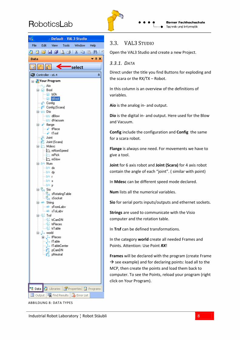
3.3. VAL3 STUDIO
Open the VAL3 Studio and create a new Project.
3.3.1. DATA
Direct under the title you find Buttons for exploding and
the scara or the RX/TX – Robot.
In this column is an overview of the definitions of
variables.
Aio is the analog in- and output.
Dio is the digital in- and output. Here used for the Blow
and Vacuum.
Config include the configuration and Config the same
for a scara robot.
Flange is always one need. For movements we have to
give a tool.
Joint for 6 axis robot and Joint (Scara) for 4 axis robot
contain the angle of each “joint”. ( similar with point)
In Mdesc can be different speed mode declared.
Num lists all the numerical variables.
Sio for serial ports inputs/outputs and ethernet sockets.
Strings are used to communicate with the Visio
computer and the rotation table.
In Trsf can be defined transformations.
In the category world create all needed Frames and
Points. Attention: Use Point RX!
Frames will be declared with the program (create Frame
see example) and for declaring points: load all to the
MCP, then create the points and load them back to
computer. To see the Points, reload your program (right
click on Your Program).
select
Your Program
ABBILDUNG 8: DATA TYPES

RoboticsLab
Industrial Robot Laboratory ¦ Robot Stäubli 9
3.3.2. PROGRAMS
A program is a sequence of VAL3 instructions to be
executed. A program consists of the following elements:
The sequence of instructions A set of local variables A set of parameters
Predefined are the start and stop programs. For a better
overview you can create new Programs.
Now open the Example program: (C:\Documents and
Settings\labo-533\My
Documents\Staubli\CS8\Default\usr\usrapp)
Start() program
The start() program is the program called when the VAL3
application is starting. It cannot have any parameters.
Typically, this program includes all the operations
required to execute the application: initialization of the
global variables and the outputs, starting up the
application tasks, etc.
The application does not terminate at the end of the
start() program, if other application tasks are still running.
The start() program can be called from within a program
(call instruction) in the same way as any other program.
Stop() program
The stop() program is the program called when the VAL3
application stops. It cannot have any parameters.
Typically, this program includes all the operations
required to stop the application correctly: resetting the
outputs and stopping the application tasks according to
an appropriate sequence, etc.
The stop() program can also be called within a program
(call instruction) in the same way as any other program
but, calling the stop() program does not stop the
application.
Your Program
ABBILDUNG 9: PROGRAMS
RoboticsLab
Industrial Robot Laboratory ¦ Robot Stäubli 10
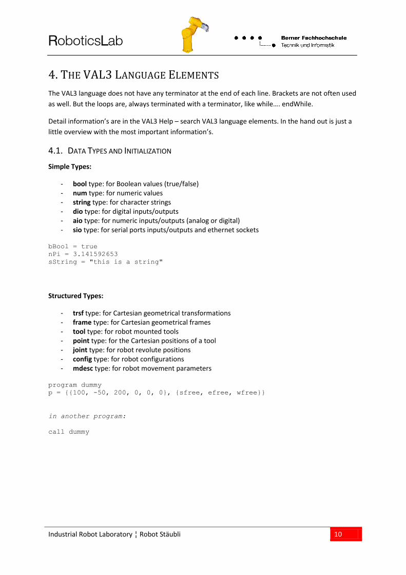
4. THE VAL3 LANGUAGE ELEMENTS
The VAL3 language does not have any terminator at the end of each line. Brackets are not often used
as well. But the loops are, always terminated with a terminator, like while…. endWhile.
Detail information’s are in the VAL3 Help – search VAL3 language elements. In the hand out is just a
little overview with the most important information’s.
4.1. DATA TYPES AND INITIALIZATION
Simple Types:
- bool type: for Boolean values (true/false) - num type: for numeric values - string type: for character strings - dio type: for digital inputs/outputs - aio type: for numeric inputs/outputs (analog or digital) - sio type: for serial ports inputs/outputs and ethernet sockets
bBool = true
nPi = 3.141592653
sString = "this is a string"
Structured Types:
- trsf type: for Cartesian geometrical transformations - frame type: for Cartesian geometrical frames - tool type: for robot mounted tools - point type: for the Cartesian positions of a tool - joint type: for robot revolute positions - config type: for robot configurations - mdesc type: for robot movement parameters
program dummy
p = {{100, -50, 200, 0, 0, 0}, {sfree, efree, wfree}}
in another program:
call dummy

RoboticsLab
Industrial Robot Laboratory ¦ Robot Stäubli 11
4.2. IMPORTANT INSTRUCTIONS
To move the robot
movel(pPosition, tTool, mDesc) moves the robot on a straight line from the actual position to the point pPosition
movej(pPosition, tTool, mDesc) movej(jPosition, tTool, mDesc)
moves the robot to a point pPosition moves the robot to a point jPosition
pPosition: is a variable “world-point scara” jPoint: is a variable “joint-scara” tTool: is a variable “flange-tool” mDesc: is a variable “Mdesc” (movement description)
Note: The difference between points and joints is that a joint position is defined by only
one arm configuration. In opposition, almost all points can be reached in two
different arm configurations (left and right) -> we saw it in chapter 2.2.1 and 2.2.2
waitEndMove() wait until the arm reaches the destination point
note: without the command waitEndMove() the controller goes on even if the movements
are not completed or it’s not even possible to complete them.
To define a specific frame and move relative to it
setFrame(pPoint01,pPoint02,pPoint03,fFrame) create a frame fFrame with the help of 3 Points
pPoint04 = compose(pPoint01, fFrame, {j*trTrsform.x,k*trTrsform.y,0,0,0,0})
create the point pPoint04 in the robot frame
movej(pPoint04, tTool, mDesc) move to point pPoint04
fFrame: is a variable “world-frame” trTrsform: is a variable “Trsf” trTrsform define the steps in x and y direction in the frame
The point pPoint04 is calculated
form the point pPoint 01 plus j
time the transformation
trTransform in x direction and k
time the transformation
trTransform in y direction j and k
are numerical increments.

RoboticsLab
Industrial Robot Laboratory ¦ Robot Stäubli 12
To use the vacuum griper
dioLink (dVacuum, io:dOut1) create a link between dVacuum and digital Output 1
dioLink (dBlow, io:dOut0) create a link between dBlow and digital Output 0
dVacuum=true ; dVacuum=false enable / disable vacuum
dBlow = true ; dBlow = false enable / disable blowing
To write or read a socket connection – general case
sioLink(<sioMessage>,io:<sioSource>) makes a link to an existing socket – connection
sioMessage: this variable must be declared local or global as an Sio type sioSource: is the name of the socket to which the connection shall be made; in our
example either labclient or portSerial. The socket is declared in the controller.
sioVariable = string to write a string to the socket
string = sioVariable to read a string from the socket
To write or read a message to OpenCV
sioLink(sSocket, io:OpenCV) create a link between sSocket a OpenCV’s PC
clearBuffer (io:OpenCV) clear the link
sToOpenCV=”send1” // “send0” assign sendO or sendE to the string sToOpenCV
sSocket = sToOpenCV transfer the message to OpenCV’s computer
sFromOpenCV = sSocket read the message from OpenCV’s computer
To control the rotating table
sioLink(sRotatingTable,io:portSerial1) create a link between sRotationTable and port serial 1
sRotatingTable = “EN” enable table rotation
sRotatingTable =”V300” set motor speed to 1000 rpm cw
sRotatingTable =”V-300” set motorspeed to 1000 rpm ccw
sRotatingTable =”DI” disable table rotation
note: There is a gear between the motor and the rotating table. The velocity will be reduced
with i=370.
Other useful instructions
toNum() Computes the numerical represented at the beginning of the string specified, and returns a string in which all the characters have been deleted until the next representation of a numerical value
toString() Returns a character string representing nValue according to the display format
insert() Returns a string which a string is inserted after positon index character
RoboticsLab
Industrial Robot Laboratory ¦ Robot Stäubli 13
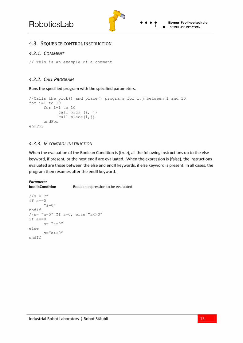
4.3. SEQUENCE CONTROL INSTRUCTION
4.3.1. COMMENT
// This is an example of a comment
4.3.2. CALL PROGRAM
Runs the specified program with the specified parameters.
//Calls the pick() and place() programs for i,j between 1 and 10
for i=1 to 10
for i=1 to 10
call pick (i, j)
call place(i,j)
endFor
endFor
4.3.3. IF CONTROL INSTRUCTION
When the evaluation of the Boolean Condition is (true), all the following instructions up to the else
keyword, if present, or the next endIf are evaluated. When the expression is (false), the instructions
evaluated are those between the else and endIf keywords, if else keyword is present. In all cases, the
program then resumes after the endIf keyword.
Parameter bool bCondition Boolean expression to be evaluated
//s = ?”
if a==0
“s=0”
endIf
//s= “a=0” If a=0, else “a<>0”
if a==0
s= “a=0”
else
s=”a<>0”
endIf

RoboticsLab
Industrial Robot Laboratory ¦ Robot Stäubli 14
4.3.4. WHILE CONTROL INSTRUCTION
The instructions between while and endWhile are executed when the Boolean Condition expression
is (true). If the Boolean Condition expression is not true at the first evaluation, the instructions
between while and endWhile are not executed.
Parameter bool bCondition Boolean expression to be evaluated
// Causes a signal to flash while the robot is working
diLamp = false
while (isSettled()==false)
diLamp = !diLamp //Inverses the value of the diLamp:true false
delay(0.5) // Waits ½ s
endWhile
diLamp = false
4.3.5. DO …. UNTIL CONTROL INSTRUCTION
The instructions between do and until are executed until the Boolean bCondition expression is
(true). The instructions between do and until are executed once if the Boolean bCondition
expression is true during its first evaluation.
Parameter bool bCondition Boolean expression to be evaluated // Waits until Enter is pressed
do
a = get() // Waits for a key to be pressed
until (a == 270) // Tests the Enter key code
4.3.6. FOR CONTROL INSTRUCTION
The instructions between for and endFor are executed until the nCounter exceeds the specified nEnd
value. The nCounter is initialized by the nBeginning value. If nBeginning exceeds nEnd, the
instructions between for and endFor are not executed. At each iteration, the nCounter is
incremented by the nStep value, and the instructions between for and endFor are repeated if the
nCounter does not exceed nEnd. If nStep is positive, the nCounter exceeds nEnd if it is greater than
nEnd. If nStep is negative, the nCounter exceeds nEnd if it is less than nEnd.
Parameter num nCounter num type variable used as a counter num nBeginning numerical expression used to initialize the counter num nEnd numerical expression used for the loop end test [num nStep] numerical expression used to increment the counter

RoboticsLab
Industrial Robot Laboratory ¦ Robot Stäubli 15
jDest = {0,0,0,0,0,0}
// Rotates axis 1 from 90° to -90° in -10-degree steps
for i = 90 to -90 step -10
jDest.j1 = i
movej(jDest, flange, mNomSpeed)
waitEndMove()
endFor
4.3.7. SWITCH CONTROL INSTRUCTION
Executes the instructions corresponding to the nSelection case specified. When a non integer value is
specified for the nSelection or for a nCase, the nearest integer is used. If no case corresponds to the
nSelection specified, the Default Instructions, if present, are executed. If the same case nCase value
occurs several times, only its last occurrence is taken into account.
Parameter num nSelection num selection type variable num nCase1 test case numerical constant num nCase2 test case numerical constant num nCase3 test case numerical constant num nCase4 test case numerical constant
num nMenu
string s
// Tests the menu key pressed
nMenu = get()
switch nMenu
case 271
s = "Menu 1"
break
case 272
s= "Menu 2"
break
case 273, 274, 275, 276, 277, 278
s = "Menu 3 to 8"
break
default
s = "this key is not a menu key"
break
endSwitch
RoboticsLab
Industrial Robot Laboratory ¦ Robot Stäubli 16
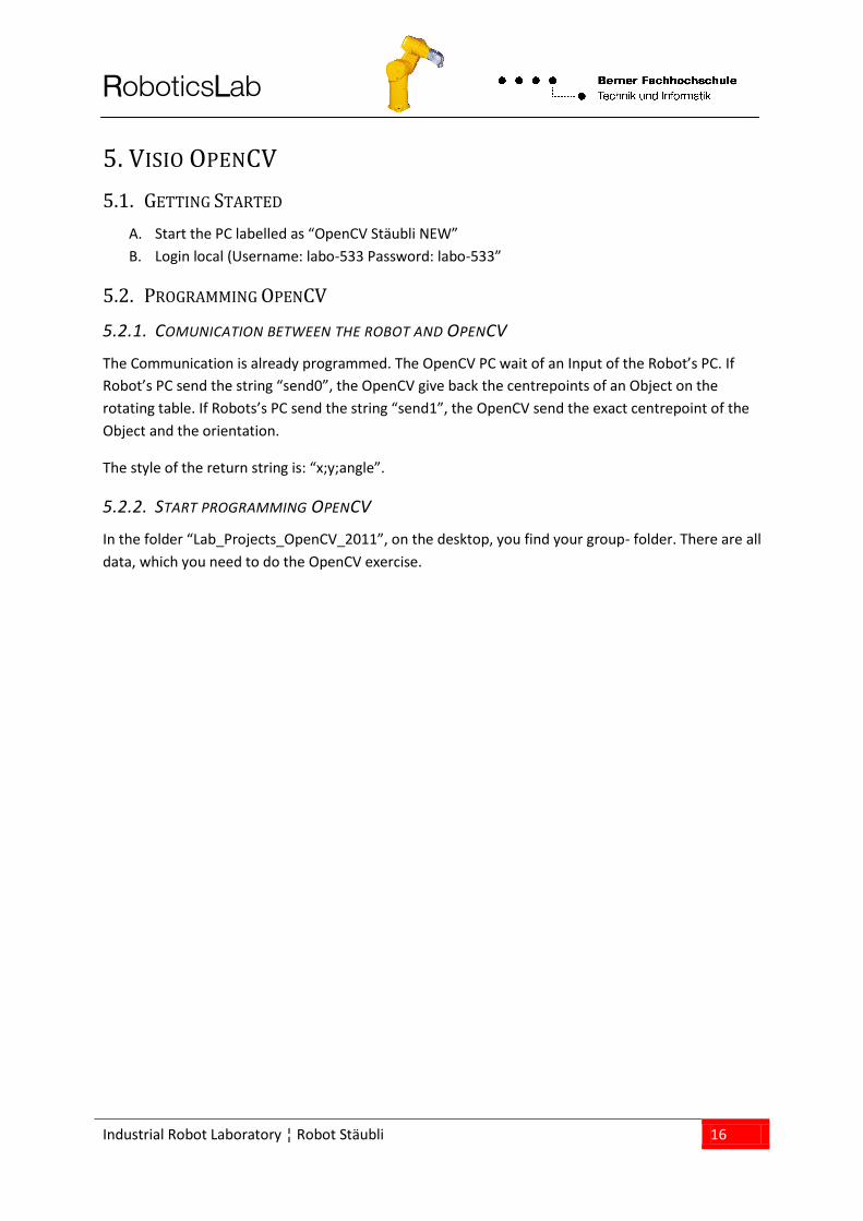
5. VISIO OPENCV
5.1. GETTING STARTED
A. Start the PC labelled as “OpenCV Stäubli NEW”
B. Login local (Username: labo-533 Password: labo-533”
5.2. PROGRAMMING OPENCV
5.2.1. COMUNICATION BETWEEN THE ROBOT AND OPENCV
The Communication is already programmed. The OpenCV PC wait of an Input of the Robot’s PC. If
Robot’s PC send the string “send0”, the OpenCV give back the centrepoints of an Object on the
rotating table. If Robots’s PC send the string “send1”, the OpenCV send the exact centrepoint of the
Object and the orientation.
The style of the return string is: “x;y;angle”.
5.2.2. START PROGRAMMING OPENCV
In the folder “Lab_Projects_OpenCV_2011”, on the desktop, you find your group- folder. There are all
data, which you need to do the OpenCV exercise.
RoboticsLab
Industrial Robot Laboratory ¦ Robot Stäubli 17
6. EXERCISES ROBOTPC
6.1. EXERCISE 1 – FIRST STEPS
start the robot
move the robot by hand
get used to the world coordinate (make a draft of the workspace and the values of the robot)
read the coordinates of the points
teach some points
move the robot from point to point
6.2. EXERCISE 2 – PICK AND PLACE MOVEMENT
make a program to move the robot like a P&P with adapted speed and precision
teach points and run the program
6.3. EXERCISE 3 – PRECISE P&P MOVEMENT
make a program to pick up a part and place it into the blister
teach all different shape positions of the blister
6.4. EXERCISE 4 – CAMERA AND ROBOT
make a calibration of the cameras and the robot
search one part, send the coordinates to the robot and do the same as in the previous
exercise.
6.5. EXERCISE 5 – ROTATING TABLE
Let the Table turn, detect pieces with the cam
follow the piece with the same speed as the table and pick up
then do the same as in the previous exercise