robust control of redundantly actuated dynamical...
TRANSCRIPT
Robust Control of Redundantly Actuated Dynamical
Systems
Manoranjan Majji∗ and John L. Junkins †
Texas A & M University, College Station, TX, 77843-3141, USA
The eigenstructure assignment scheme for robust multivariable state feedback control
is extended to redundantly actuated dynamical systems. The fact that the plants that
are atleast square allow for the exact assignment of an arbitrary orthonormal set of closed
loop eigenvectors makes this methodology attractive for feedback controller design poorly
modeled dynamical systems. For second order mechanical systems, a partial eigenstruc-
ture assignment methodology is presented which simplifies the scheme of pole assignment
for real target sub-modal matrix. An optimal allocation strategy is derived for redundant
control inputs to minimize an integral cost function. A novel adaptive aggregation pro-
cedure is introduced to handle problems with very high redundancy in actuation. The
aggregation approach along with the eigenstructure assignment methodology is applied to
the wing morphing problem. The robust redundant actuation procedure is demonstrated
on a mathematical model constructed from the wind tunnel test data of the novel morphing
wing model designed and developed at Texas A & M University.
Nomenclature
A System Matrix of a linear dynamical systemB Control Influence Matrixx Vector of State Variablesu Vector of Control VariablesM Mass matrix of a second order mechanical systemC Damping matrix of a second order mechanical systemK Stiffness matrix of a second order mechanical systemq Vector of generalized coordinatesσ(.) Singular Value of (.)‖(.)‖ Frobenius norm of (.)η Vector of modal coordinatesSubscript
i Variable number
I. Introduction
Redundancy in sensing and actuation has taken center stage in control of modern day dynamical systemsowing to their complex functionality and increased performance targets. Classical control theory beingdeveloped for under-actuated systems, with the fundamental considerations of stability in regulation ortracking. The advent of redundancy enables the engineer to design for increased goals of system performancesuch as robustness (to model errors and other perturbations),coordination (of redundant actuator sets) andreliability enhancement (in case of actuator failure). This proposes robust solutions and implementationmethods for the actuator redundancy problem at several levels. Let us first look at some applications in lieuof the emerging importance of redundantly actuated dynamical systems.
∗Graduate Research Assistant, Aerospace Engineering Department, Student Member, AIAA.†George J. Eppright Chair, Distinguished Professor, Aerospace Engineering Department, Fellow, AIAA.
1 of 16
American Institute of Aeronautics and Astronautics
In robotic systems, redundancy is handled by several strategies. One particular approach shown in Naka-mura uses a prioritization approach achieving local/global optimal control formulations.18 Typical appli-cations include robots with parallel actuated wrists and dexterous fingers. Modeling of such closed linkrobot mechanisms with redundant actuators poses an equally difficult challenge. The advantages of redun-dancy in handling actuator failure and in optimizing load distribution were pointed out by Nakamura andGhodoussi.19 They suggested modeling of redundant joints by equivalent open chains and control opti-mization was done by a simple optimization scheme. A simpler dynamics methodology with a comparisonof several redundant control schemes was proposed by Cheng.20 A computationally fast methodology formulti-fingered grasping applications, Dynamics Force Distribution, is presented by Zheng.21 Junkins et al.,22
propose a novel methodology for coordination of redundant sets of actuators in multibody systems with aweighted pseudoinverse, with weights determined by the current work space coordinates.
In aircraft control problems, with the on-set of non-traditional control surfaces, the redundant actuationmethods have taken a center stage, in recent times, with increase in computation power and hardwarecapacities. Prioritization of redundant actuator sets is one of the methods of handling redundancy in aircraftcontrol, such schemes, called ”Daisy Chain Control Allocation” were first demonstrated by Buffington.25
When the redundant sets of actuators are actually constrained by their operation limits, Durham10 proposesconstrained control allocation schemes. Bodson9 presents an overview of constrained control allocationstrategies. In the presence of actuator constraints, the pseudo-inverse solution cannot meet the demandedaccelerations computed from a square plant. In the light of the same, direct allocation, which Bodsonposes as a linear programming problem, presents a highly desirable candidate for real-time application.Singla27 proposes an approximation approach to recursively allocate using adaptive distribution functionsaddressing the high dimensionality of the control space with computational efficiency with an application tothe morphing problem.
In spacecraft attitude control problems, the Control Moment Gyros (CMG) and Reaction Wheels forma major class of actuators. Four Single Gimbal CMGs (SGCMGs) in a pyramidal configuration, forma redundant set of actuators in the reorientation maneuvers of spacecraft. Design of a steering law forredundant SGCMGs was modified by Bedrossian26 to avoid such singularities. Schaub, et.al.,24 extendedthis methodology to obtained control laws for variable speed CMGs for a better redistribution of the internalmomentum.
Organization
The paper is organized as follows. Section II presents the robust eigenstructure assignment algorithm withapplication to redundantly actuated dynamical systems. The method’s relavance originates from the factthat any orthogonal closed loop target is always exactly assignable when the plant is atleast square. Thisscheme is then extended to second order systems via a simple technique called the partial eigenstructureassignment. The allocation of thus calculated robust control among redundant actuator sets is carried outby a control distribution scheme posed as an optimal control problem. The open loop version of this schemeis demonstrated on an emprirical model of a novel morphing wing designed and developed at Texas A&MUniversity. For hyperredundant actuation (required for appliction in smart actuator arrays), an adaptiveaggregation scheme is developed to group actuators in to finite groups so that the reduced order modelsbecome amenable for allocation methods. Some conclusions and future directions are presented later.
2 of 16
American Institute of Aeronautics and Astronautics
II. Robust Eigenstructure Assignment
Eigenstructure assignment is an established tool for robust control of state-space models by state andoutput feedback.1,2 The flexibility of hte methodology to allow the designer to explore the arbitrariness ofthe closed loop admissible eigenvectors in addition to the pole assignment made the method a popular toolfor feedback gain calculations. it is well known that near orthogonality of the closed loop eigenvectors isdesirable to minimize sensitivity of the eigenvalue placement to the model errors. Arbitrary selection of theclosed loop eigenvectors can lad to a higly sensitive gain matrix, making the conditioning of the closed loopmodal matrix a key issue in the achievement of robustness of the controller to plant parametric uncertainties.The design process can be summarized as follows.
II.A. Eigenstructure Assignment
Consider the following state space description of a linear dynamical system
x = Ax + Bu (1)
x(t0) = x0 (2)
with a state feedback control law, u = −Gx where A ∈ <n×n, B ∈ <n×m, G ∈ <m×n. resulting in a closedloop of the form,
x = (A − BG)x (3)
The corresponding closed loop eigenvalue problems can be written as
(A − BG)φi = λiφi (4)
(A − BG)T ψi = λiψi (5)
with the left and right eigenvectors φiψi being normalized according to the conditions φTi ψi = 1, ψT
i φj = δij .By introducing a parameter vector, hi = Gφi, the problem of calculation of the gain matrix, G, becomes thesolution of the matrix Sylvester equation,
AΦ − ΦΛ = BH (6)
where Φ = [φ1, φ2, ..., φn], Λ = diag [λ1, λ2, ..., λn] and H = [h1, h2, ..., hn] = GΦ. For a given target modalmatrix, Φ, we would need to solve for the gain matrix, G, that would bring about the assignment of therequired closed loop eigenvectors. The robustness of this scheme is derived from a theorem due to Patel andToda,.3 We state the theorem and discuss the robustness properties.
Theorem II.1 (Patel and Toda3) Consider the asymptotically stable closed loop system x = ACLx. The
perturbed closed loop system matrix, ACL + ∆ of the original system remains asymptotically stable for all
perturbations, ∆, bounded by
‖∆‖ <min[−<λ(ACL)]
κ(ΦCL)(7)
where, ΦCL is the closed loop modal matrix, κ(.) is the condition number defined as the ratio of the maximum
to the minimum singular values of the matrix, (.) and <{.}, denoting the real part of {.}.
Proof The proof of this theorem is given by Patel and Toda3 and by Junkins and Kim1 using Lyapunovtheory. This theorem is the manifestation of the intimate connection between the conditioning of the algebraiceigenvalue problem and the robustness stability margin for a linear dynamical system subject to additiveplant parameter perturbations. ¤
Therefore, in principle, for a square plant (a plant model with atleast as many actuators as the numberof state variables, m ≥ n), any additive parametric perturbation can be compensated by state feedback viaeigenstructure assignment. This application to redundantly actuated dynamical systems is summarized bythe following theorem.
3 of 16
American Institute of Aeronautics and Astronautics
Theorem II.2 A redundantly actuated linear dynamical system,
x(t) = Ax + Bu (8)
controlled by a linear full state feedback control law, u = −Gx, u ∈ <m,m ≥ n, B full row rank, with
G = B†(AΦ − ΦΛCL), where Φ is a target orthonormal set of closed loop eigenvectors and the Hurwitz
target closed loop eigenvalue matrix, ΛCL, chosen such that, min{−<{λ(i)CL}} > ‖∆‖2, ensures the robust
stabilization of the linear system to all perturbations bounded in magnitude by the matrix norm ‖∆‖2
Proof The proof follows from theorem 1. Because, m ≥ n, atleast one gain matrix exists to solve theSylvester equation exactly as shown below (n2 equations in mn variables).
(AΦ − ΦΛCL)Φ−1 = BG (9)
(10)
Further, the choice of an orthonormal matrix for closed loop modal matrix, Φ, together with Patel Todatheorem II.1, ensure the closed loop poles to satisfy the following bound (with the additional fact of perfectconditioning of the closed loop modal matrix, κ(Φ) = 1).
‖∆‖2 < min{−<{λ(i)CL}} (11)
This ensures the robust stabilization. ¤
II.B. Second Order Mechanical Systems: Partial Eigenstructure Assignment
In mechanical systems, often, it is desired to construct very high order plant models (For Eg., flexiblestructures). Also, in such structural mechanicas models, the kinematics remain unforced. Therefore, itis important to understand how the above results for redundant actuation translate to the second ordermechanical systems. Accordingly, a classic paper by Hughes and Skelton,4 specializes the known results forfirst order state space models to second order models, important for mechanical systems. This motivatedmany control theorists to search for a second order extension to eigenstructure assignment scheme. Juanget. al.,5 propose a Eigenstructure assignment for second order systems by an IMSC method. Juang andMaghami6 extended this, by incorporating a sequential scheme that assigns the closed loop eigenvectors usingsubspace intersection between the desired closed loop eigenspace and the assignable subspace of eigenvectors.Kim et. al.,7 propose a computationally efficient method of achieving the same.
In the same spirit, we present a partial eigensystem assignment algorithm for second order mechanicalsystems. Apart from its elegance, this methodology is computationally very attractive, especially for highorder models, where the real time compuation of feedback gains is an important problem.
Most of the second order mechanical systems, in practice allow the assignability of a part of the eigen-structure. This is because, the external forces do not apply directly on the kinematics part of the dynamicalsystem. It therefore follows from the developments of Srinathkumar,8 that only n components (of the total2n state variables, ofcourse assuming there are atleast n) of each mode can be assigned arbitrarily. Thisis sufficient for most practical applications, if we desire a complex conjugate pair of target set of closedloop eigenvalues. This is because of the following structure of the modal matrix for any linear second ordermechanical system.
Θ =
(
Φ Φ
ΦΛ ΦΛ
)
(12)
Clearly, because of the constraints from the kinematics and the complex conjugate eigenvalues of the secondorder system, the determination of the n × n principal sub modal matrix, Φ, determines the entire modalmatrix. We utilize this fact and try and make the principal sub modal matrix, Φ, as well conditioned aspossible. Now we develop a systematic method to do the partial EsA.
4 of 16
American Institute of Aeronautics and Astronautics
Let the second order mechanical system be given by
Mx + Cx + Kx = Bu (13)
with M ∈ n × n, x ∈ <n, u ∈ <m, B ∈ <m×n, and m ≥ n, rank(B) = n. With a position and velocityfeedback, u = Gx = G1x+G2x, the closed loop eigen value problem for the second order mechanical systemis given by
(
Mλ2i + (C − BG2)λi + (K − BG1)
)
φi = 0 (14)
where, λi ∈ Cn = λRi + jλIi, λRi, λIi ∈ < and j2 = −1. We assign a set of distinct complex target poles andtheir conjugates are assigned automatically. Consider a real n × n principal modal sub-matrix. A unitarytarget for sub modal matrix makes the problem more complicated, with coupled matrix equations to solvefor the required feedback gain matrices. For simplicity and elegance, we consider the real sub-matrix in thispaper. Separating the real and imaginary parts of the above equation, we get the following two conditions,
(
M(λ2Ri − λ2
Ii) + (C − BG2)λRi + (K − BG1))
φi = 0 (15)
j (2MλRiλIi + (C − BG2)λIi) φi = 0 (16)
Clearly the equations above represent a cascade and one of them is the matrix Sylvester equation, we sawearlier. From the above conditions, together with the fact that we can assign a target n×n principal modalsub matrix exactly owing to the fact that the plant is atleast square, we have the following feedback gains.
G2 = B−1(C + 2MΦΛRΦT ) (17)
G1 = B−1(MΦ(Λ2R − Λ2
I)ΦT − 2MΦΛ2
RΦT + K) (18)
It is found that these gains assign the closed loop poles along with the principal target modal sub-matrixexactly (subject to appropriate scaling and complex magnitude considerations). We demonstrate the samewith the following example problem (example 5.4 from Junkins and Kim1) and discuss the positive featuresof the algorithm proposed above.
II.B.1. Example
Consider the undamped open loop second order system with the following parameters,
M =
1 0 0
0 1 0
0 0 1
,K =
20 −10 0
−10 30 −20
0 −20 20
(19)
With such parameter matrices, consider the target eigenstructure given by Λtarget = diag (−0.72 +1.24i,−0.72−1.24i,−2.235+3.87i,−2.23−3.87i,−3.4+5.9i,−3.4−5.9i), that is ω1 = 1.44, ω2 = 4.47, ω3 =6.92, ζ1 = ζ2 = ζ3 = 0.5. The assigned eigenvalues computed from the above methodology and thecorresponding closed loop eigenvectors are shown below.
Λ = diag(−0.72 + 1.24i,−0.72 − 1.2i,−2.2 + 3.8i,−2.2 − 3.8i,−3.46 + 5.9i,−3.46 − 5.9i), (20)
Φ =
−0.52218 − 0.533i 0 0
0 −0.11656 − 0.1935i 0
0 0 −0.0737 − 0.125i
1.0405 − 0.0267i 0 0
0 1.012 − 0.022i 0
0 0 1.0051 − 0.00918i
(21)
The above equations are the representative modes of closed loop system. The other three modes are thecomplex conjugates of the above modes. At first blush, it may seem that this is not the eigenstructure wewanted. That is due to the bi-orthogonality conditions we imposed for normalization. Upon dividing each
5 of 16
American Institute of Aeronautics and Astronautics
column so as to make the principal sub-modal matrix unity, we unravel the following scaled modes (That isdivide ith eigenvector with its i, ith entry, in the above set).
Φscaled =
1 0 0
0 1 0
0 0 1
−0.72 + 1.2471i 0 0
0 −2.235 + 3.8711i 0
0 0 −3.46 + 5.9929i
(22)
Clearly, this was the target eigenstructure. We also recover the condition number by this scaling to havethe same conditioning as the target modal matrix. This can be compared with the solution by projectionmethod in Junkins and Kim1 in table 5.3. Comparing with the projection method, using a unitary matrixas a target, the norm of the feedback gains required was ‖G‖F = 50.91, where as in this case, the norm ofthe gain matrix was found to be ‖G‖F = 37.363.
Thus we can see from the above that we need not always use a projection method to stay as close aspossible to a known, well conditioned system. It is also of consequence if we concentrate on the assignablesub modal matrix as the second order mechanical systems have a special structure and with a square plant,we can always assign the assignable target sub matrix.
II.B.2. Features of the Partial EsA algorithm
Whenever possible, the partial EsA algorithm has the following advantages and disadvantages when comparedto its cousins proposed in Juang and Maghami,6 Juang et.al.,5 and Kim, et.al.,.7
• The algorithm above is computationally lesser expensive than its cousins. Juang5 algorithm usesSVD for each eigenvalue/vector assignment and a matrix inverse is required, whereas we need onlyone matrix inverse. Juang6’s method requires a QR step and an SVD for each eigenvalue/vector asthe procedure uses angle between subspaces. Kim’s approach is actually quite similar to the presentapproach, but does not use the fine matrix manipulations as the above algorithm.
• This algorithm doesn’t need the modal damping assumption which is important for Kim’s algorithm.The damping can be asymmetric. Infact, the only restriction we need in the above development is tohave an invertible (or pseudo-invertible) control influence matrix and a positive definite mass matrix.
• The limitation of this method is that we need atleast n actuators for 2n state variables in the secondorder form. This can be relaxed but we cannot assign the target submodal matrix exactly. this wouldentail us to use a projection criterion to minimize the error between assignable vectors and ideal targetvectors.
• The method needs an extension to assign complex principal modal sub matrices. This brings about achange in the structure of the conditions that need to be satisfied.
• An arbitrary selection of target eigenvector set can lead to very high gains and a sensitive feedbackcontroller. Therefore we need to select the target modal matrices judiciously.
Therefore, eigenstructure assignment methodology forms an important class of robust control design strate-gies. Notice that we have not thusfar, specialized the method for redundantly actuated dynamical systems.The computation of control input to individual actuators is in turn done by a minimum norm solution. Inthe next section we present a novel alternative scheme to distribute this control input among the individualactuators using an optimality criterion.
6 of 16
American Institute of Aeronautics and Astronautics
III. Redundant Control Allocation
Control Allocation problem focusses on allocating the control authority to individual inputs of the re-dundant actuator sets, so as to produce a desired total force/moment specified by a control law (equal indimension to the state vector). The allocation process, in general, does not constitute the control law. Theallocation of authority becomes especially important in the presence of control variable inequality constraints,as clipping the pseudoinverse solution to satisfy the constraints leads to improper usage of redundancy. Anexcellent survey of existing methods to solve this problem is given by Bodson.9 Durham’s10 Direct allocationalong with several other optimization criteria such as the error minimization and control minimization arediscussed and associated algorithms are presented.
In this section, we propose a slightly different formulation to the allocation problem with certain desirablefeatures. Consider the square reference model and the plant with redundant inputs given by
˙ym = Aym + ad (23)
y = Ay + Bu (24)
where u ∈ <m, ad, y, ym ∈ <n,m > n. ad is the control law computed for the square plant model (in our caseusing a robust eigensystem assignment statefeedback scheme). Define tracking error e ≡ ym − y leading tothe error dynamics, e = Ae + Bu − ad. The following allocation scheme minimizes an integral cost function
min J = e(tf )T Sfe(tf ) +1
2
∫ tf
t0
uT Ru + (Bu − ad)T Γ(Bu − ad) + eT Qe dt (25)
subject to e = Ae + (Bu − ad) (26)
umin ≤ u(t) ≤ umax (27)
Hamiltonian can be written as
H(x, u, λ, µ1, µ2, t) =1
2
(
uT Ru + (Bu − ad)T Γ(Bu − ad) + eT Qe
)
+λT (Ae+Bu−ad)+µT1 (u−umax)+µT
2 (umin−u)
(28)The necessary conditions for optimality are given by
Hu = Ru + BT ΓBu − BT Γad + BT λ + µ1 − µ2 = 0 (29)
λ = −Qe − AT λ (30)
e = Ae + Bu − ad (31)
with boundary conditions e(t0) = e0, λ(tf ) = Sfe(tf ).
Remarks In the above formulation, the integral cost function penalizes the deviations from the desiredcontrol inputs ad, keeping the inputs u finite and ensuring the boundedness of the state variables. Guessesfor active times of the inequality constraints and an initial guess for λ(t0), that ensures the convergence attf is required.
On the other hand, if it is known that the control variable inequality constraints do not become activewithin the interval [t0, tf ], a feedback solution can be implemented which involves the solution similar toa linear quadratic tracking controller. This is desirable to avoid the determination of initial guesses. Thefeedback solution is given by u(t) =, where,λ(t) = −S(t)x(t)− v(t) where the gains S(t), v(t) are calculatedbackwards in time as a solution to the matrix differential equations
S + AT S + SA − SB(R + BT ΓB)−1BT S + Q = 0 (32)
v + AT v − SB(R + BT ΓB)−1BT v + S(B(R + BT ΓB)−1BT Γ − I)ad = 0 (33)
with boundary conditions S(tf ) = Sf , v(tf ) = 0.
7 of 16
American Institute of Aeronautics and Astronautics
III.A. Example: Application to the Morphing Wing
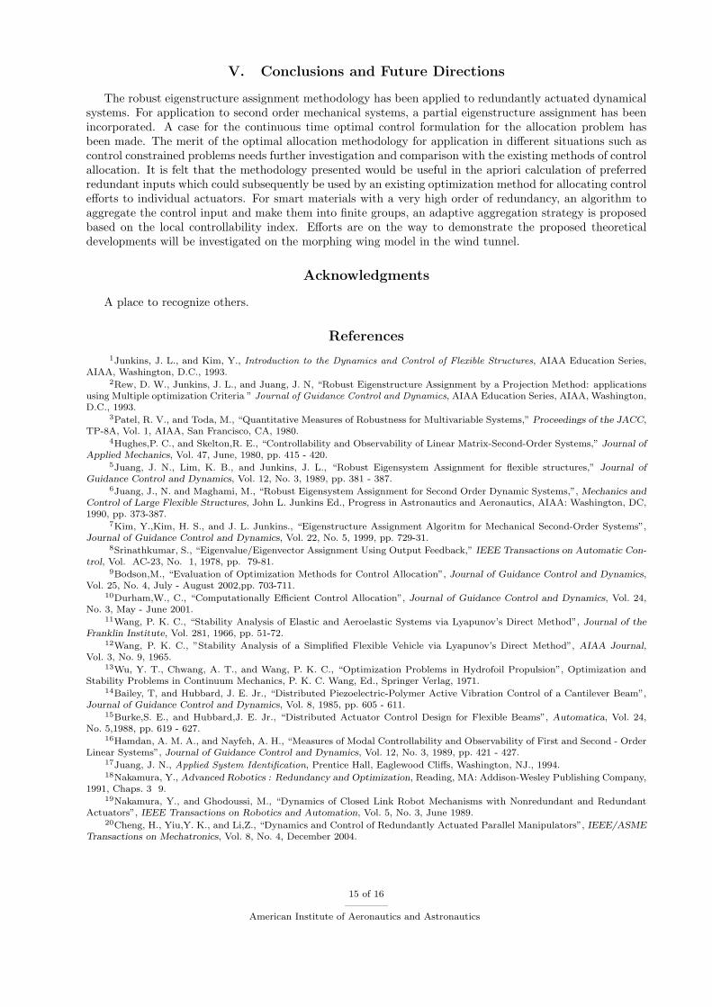
The open loop strategy of control allocation is applied to an empirical model of a novel morphing wing. Thewing, shown in Fig. 4, consists of three twisting sections that change the wing twist profile, owing to theelastomeric skin that deforms on a flexible skeleton. Considering the wing as a control surface producingonly Lift force and Rolling moments, it becomes a redundantly actuated system with the twist rates andangle of attack rate as control variables. From these an approximate model for the rate of change of lift andmoment, for a steady potential flow (Assuming the rates are sufficiently slow to neglect the unsteady effects)would be
dCL
dt=
∂CL
∂αα +
∂CL
∂θ1θ2 +
∂CL
∂θ2θ2 +
∂CL
∂θ3θ3 (34)
dCM
dt=
∂CM
∂αα +
∂CM
∂θ1θ2 +
∂CM
∂θ2θ2 +
∂CM
∂θ3θ3 (35)
where CL, CM are the lift and rolling moment coefficients and αθ1, θ2, θ3, being the angle of attack and twistangles at first, second and tip twisting sections respectively.
Static wind tunnel tests for the wing at several configurations were performed in the low speed wind tunnelat Texas A & M University. From the test data, the sensitivites for each input were calculated and thus wehave the following model for the system above. Therefore the model is valid only for sufficiently small ratesof change of angle of attach and the twist angles.
[
CL
˙CM
]
=
[
0.0836 0.041 0.0255 0.0105
−0.0499 −0.0281 −0.015 −0.0105
]
α
θ1
θ2
θ3
(36)
Consider, for simplicity, the unconstrained solution for this problem. Let the state feedback gains be calcu-lated by an Eigenstructure assignment methodology assuming two inputs and a control effectiveness matrixto be identity matrix as shown
ad = −G[CLCM ]T (37)
G = (AΦ − ΦΛCL)Φ−1 (38)
where for the problem of interest A = 02×2. Consider a solution to this problem using the open loop approachdiscussed in this section denoted by uredundant. Let us compare this solution with a solution obtained bypseudoinverse denoted by upseudoinverse ≡ BT (BBT )−1ad. These solutions are presented for a tf = 10seconds in the following figures
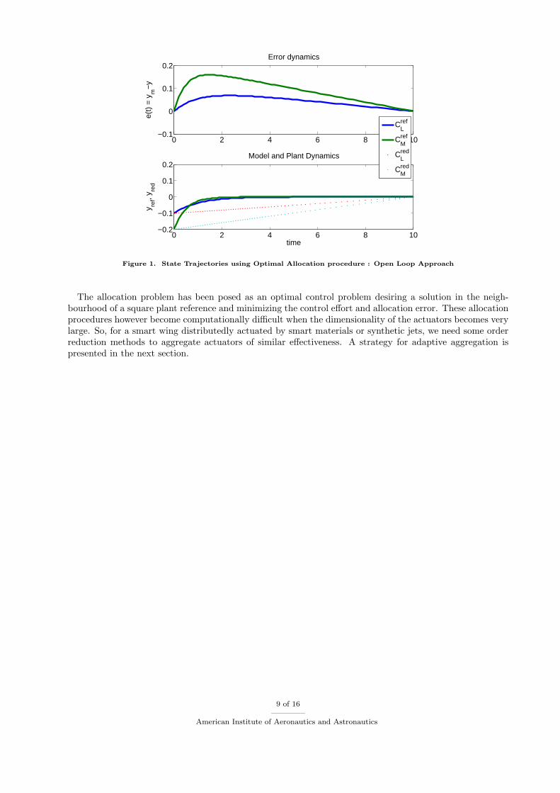
Figure 1 shows the error dynamics e(t) along with the state trajectories of the redundantly actuated planty(t) and its square reference model ym(t). Because of the terminal cost O(‖Sf‖) = 1e6, the error goes toa small number at tf . There are no large departures from the reference model as specified by the integralcost function. Perfect asymptotic tracking is not always possible as we are also minimizing the total energyinput uredundant, although this can be specified by changing the weights or posing the problem in a differentmanner. The merit of the methodology in asymptotic tracking needs further investigation. In practical
applications, for a small initial time, one can use this methodology and then switch to pseudoinverse solution
after redundant input values become sufficiently small to avoid large initial transience due to state feedback.
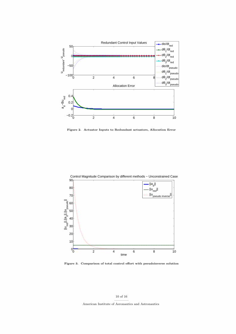
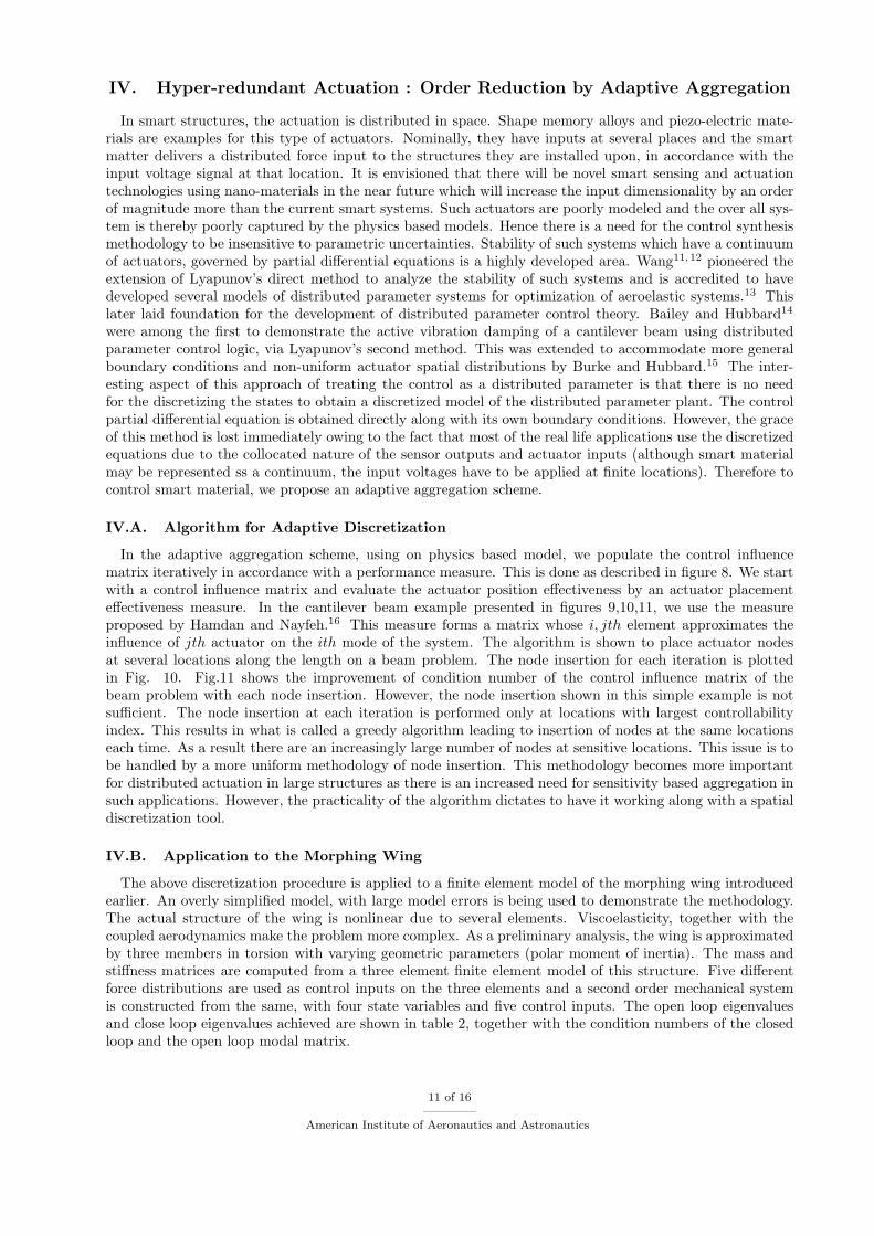
Figure 2 compares the redundant input values from the above methodology (subscript red and the classicalpseudoinverse solution (subscript pseudo). ). Note many desirable features of this solution. First, the controlappears to be devoid of large rates. This is important for our application as accelerating θis cause unsteadyeffects and violate the modelling assumptions. The method yields a rate which has very small acceleration,this is highly desirable for the application at hand. Then, the magnitude is much lower in the initial phasewhen the pseudoinverse solution yields a large magnitude. Figure 3 also shows the same. Also, the methodminimizes the allocation error. Therefore, as indicated previously, this allocation method can be used toretain stability in the initial high magnitude transience and then one can switch back to the pseudo inversesolution.
8 of 16
American Institute of Aeronautics and Astronautics
0 2 4 6 8 10−0.1
0
0.1
0.2Error dynamics
e(t)
= y
m−
y
0 2 4 6 8 10−0.2
−0.1
0
0.1
0.2
y ref, y
red
Model and Plant Dynamics
time
CLref
CMref
CLred
CMred
Figure 1. State Trajectories using Optimal Allocation procedure : Open Loop Approach
The allocation problem has been posed as an optimal control problem desiring a solution in the neigh-bourhood of a square plant reference and minimizing the control effort and allocation error. These allocationprocedures however become computationally difficult when the dimensionality of the actuators becomes verylarge. So, for a smart wing distributedly actuated by smart materials or synthetic jets, we need some orderreduction methods to aggregate actuators of similar effectiveness. A strategy for adaptive aggregation ispresented in the next section.
9 of 16
American Institute of Aeronautics and Astronautics
0 2 4 6 8 10−100
−50
0
50Redundant Control Input Values
u redu
ndan
t, ups
eudo
dα/dtred
dθ1/dt
red
dθ2/dt
red
dθ3/dt
red
dα/dtpseudo
dθ1/dt
pseudo
dθ2/dt
pseudo
dθ3/dt
pseudo
0 2 4 6 8 10−0.2
0
0.2
0.4
Allocation Error
a d−B
u red
Figure 2. Actuator Inputs to Redundant actuators, Allocation Error
0 2 4 6 8 100
10
20
30
40
50
60
70
80
90Control Magnitude Comparison by different methods − Unconstrained Case
time
||ure
d||,||a
d||,||u
pseu
do||
||ad||
||ured
||
||upseudo inverse
||
Figure 3. Comparison of total control effort with pseudoinverse solution
10 of 16
American Institute of Aeronautics and Astronautics
IV. Hyper-redundant Actuation : Order Reduction by Adaptive Aggregation
In smart structures, the actuation is distributed in space. Shape memory alloys and piezo-electric mate-rials are examples for this type of actuators. Nominally, they have inputs at several places and the smartmatter delivers a distributed force input to the structures they are installed upon, in accordance with theinput voltage signal at that location. It is envisioned that there will be novel smart sensing and actuationtechnologies using nano-materials in the near future which will increase the input dimensionality by an orderof magnitude more than the current smart systems. Such actuators are poorly modeled and the over all sys-tem is thereby poorly captured by the physics based models. Hence there is a need for the control synthesismethodology to be insensitive to parametric uncertainties. Stability of such systems which have a continuumof actuators, governed by partial differential equations is a highly developed area. Wang11,12 pioneered theextension of Lyapunov’s direct method to analyze the stability of such systems and is accredited to havedeveloped several models of distributed parameter systems for optimization of aeroelastic systems.13 Thislater laid foundation for the development of distributed parameter control theory. Bailey and Hubbard14
were among the first to demonstrate the active vibration damping of a cantilever beam using distributedparameter control logic, via Lyapunov’s second method. This was extended to accommodate more generalboundary conditions and non-uniform actuator spatial distributions by Burke and Hubbard.15 The inter-esting aspect of this approach of treating the control as a distributed parameter is that there is no needfor the discretizing the states to obtain a discretized model of the distributed parameter plant. The controlpartial differential equation is obtained directly along with its own boundary conditions. However, the graceof this method is lost immediately owing to the fact that most of the real life applications use the discretizedequations due to the collocated nature of the sensor outputs and actuator inputs (although smart materialmay be represented ss a continuum, the input voltages have to be applied at finite locations). Therefore tocontrol smart material, we propose an adaptive aggregation scheme.
IV.A. Algorithm for Adaptive Discretization
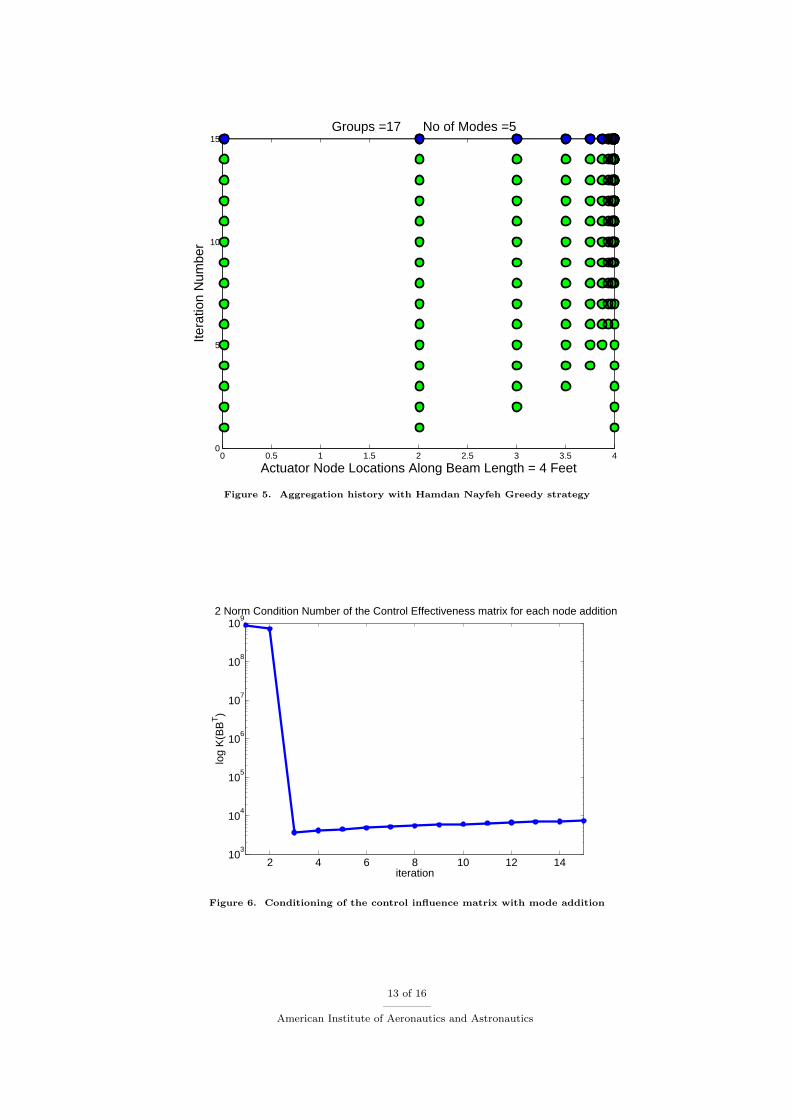
In the adaptive aggregation scheme, using on physics based model, we populate the control influencematrix iteratively in accordance with a performance measure. This is done as described in figure 8. We startwith a control influence matrix and evaluate the actuator position effectiveness by an actuator placementeffectiveness measure. In the cantilever beam example presented in figures 9,10,11, we use the measureproposed by Hamdan and Nayfeh.16 This measure forms a matrix whose i, jth element approximates theinfluence of jth actuator on the ith mode of the system. The algorithm is shown to place actuator nodesat several locations along the length on a beam problem. The node insertion for each iteration is plottedin Fig. 10. Fig.11 shows the improvement of condition number of the control influence matrix of thebeam problem with each node insertion. However, the node insertion shown in this simple example is notsufficient. The node insertion at each iteration is performed only at locations with largest controllabilityindex. This results in what is called a greedy algorithm leading to insertion of nodes at the same locationseach time. As a result there are an increasingly large number of nodes at sensitive locations. This issue is tobe handled by a more uniform methodology of node insertion. This methodology becomes more importantfor distributed actuation in large structures as there is an increased need for sensitivity based aggregation insuch applications. However, the practicality of the algorithm dictates to have it working along with a spatialdiscretization tool.
IV.B. Application to the Morphing Wing
The above discretization procedure is applied to a finite element model of the morphing wing introducedearlier. An overly simplified model, with large model errors is being used to demonstrate the methodology.The actual structure of the wing is nonlinear due to several elements. Viscoelasticity, together with thecoupled aerodynamics make the problem more complex. As a preliminary analysis, the wing is approximatedby three members in torsion with varying geometric parameters (polar moment of inertia). The mass andstiffness matrices are computed from a three element finite element model of this structure. Five differentforce distributions are used as control inputs on the three elements and a second order mechanical systemis constructed from the same, with four state variables and five control inputs. The open loop eigenvaluesand close loop eigenvalues achieved are shown in table 2, together with the condition numbers of the closedloop and the open loop modal matrix.
11 of 16
American Institute of Aeronautics and Astronautics
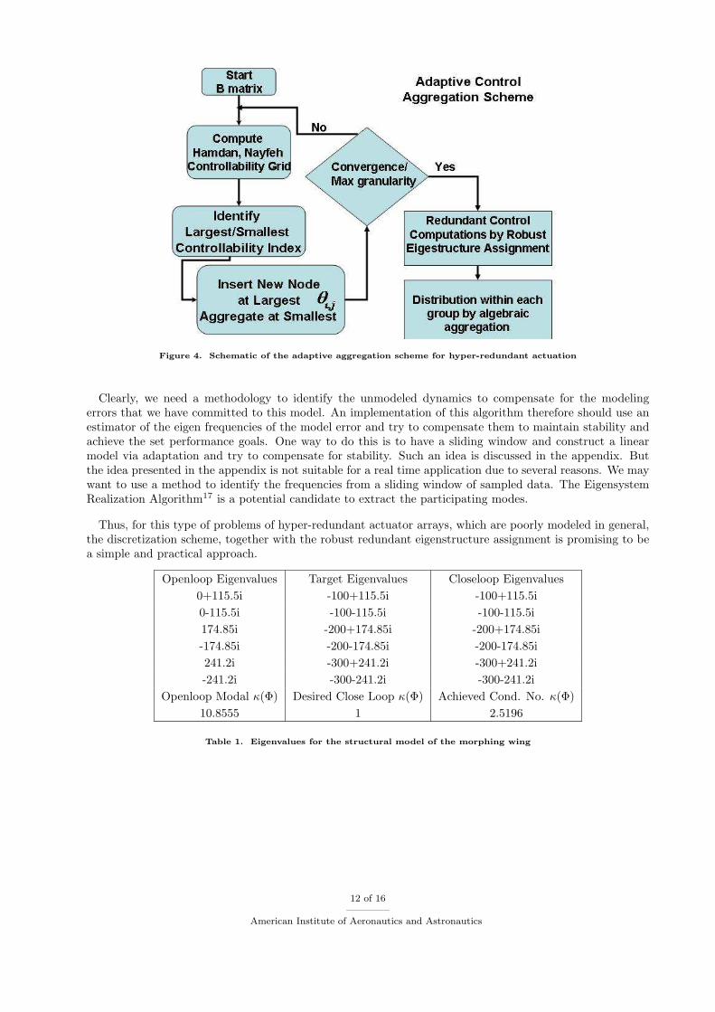
Figure 4. Schematic of the adaptive aggregation scheme for hyper-redundant actuation
Clearly, we need a methodology to identify the unmodeled dynamics to compensate for the modelingerrors that we have committed to this model. An implementation of this algorithm therefore should use anestimator of the eigen frequencies of the model error and try to compensate them to maintain stability andachieve the set performance goals. One way to do this is to have a sliding window and construct a linearmodel via adaptation and try to compensate for stability. Such an idea is discussed in the appendix. Butthe idea presented in the appendix is not suitable for a real time application due to several reasons. We maywant to use a method to identify the frequencies from a sliding window of sampled data. The EigensystemRealization Algorithm17 is a potential candidate to extract the participating modes.
Thus, for this type of problems of hyper-redundant actuator arrays, which are poorly modeled in general,the discretization scheme, together with the robust redundant eigenstructure assignment is promising to bea simple and practical approach.
Openloop Eigenvalues Target Eigenvalues Closeloop Eigenvalues
0+115.5i -100+115.5i -100+115.5i
0-115.5i -100-115.5i -100-115.5i
174.85i -200+174.85i -200+174.85i
-174.85i -200-174.85i -200-174.85i
241.2i -300+241.2i -300+241.2i
-241.2i -300-241.2i -300-241.2i
Openloop Modal κ(Φ) Desired Close Loop κ(Φ) Achieved Cond. No. κ(Φ)
10.8555 1 2.5196
Table 1. Eigenvalues for the structural model of the morphing wing
12 of 16
American Institute of Aeronautics and Astronautics
0 0.5 1 1.5 2 2.5 3 3.5 40
5
10
15 Groups =17 No of Modes =5
Actuator Node Locations Along Beam Length = 4 Feet
Itera
tion
Num
ber
Figure 5. Aggregation history with Hamdan Nayfeh Greedy strategy
2 4 6 8 10 12 1410
3
104
105
106
107
108
109
log
K(B
BT)
iteration
2 Norm Condition Number of the Control Effectiveness matrix for each node addition
Figure 6. Conditioning of the control influence matrix with mode addition
13 of 16
American Institute of Aeronautics and Astronautics
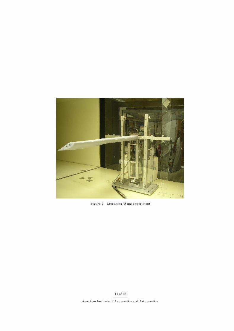
Figure 7. Morphing Wing experiment
14 of 16
American Institute of Aeronautics and Astronautics
V. Conclusions and Future Directions
The robust eigenstructure assignment methodology has been applied to redundantly actuated dynamicalsystems. For application to second order mechanical systems, a partial eigenstructure assignment has beenincorporated. A case for the continuous time optimal control formulation for the allocation problem hasbeen made. The merit of the optimal allocation methodology for application in different situations such ascontrol constrained problems needs further investigation and comparison with the existing methods of controlallocation. It is felt that the methodology presented would be useful in the apriori calculation of preferredredundant inputs which could subsequently be used by an existing optimization method for allocating controlefforts to individual actuators. For smart materials with a very high order of redundancy, an algorithm toaggregate the control input and make them into finite groups, an adaptive aggregation strategy is proposedbased on the local controllability index. Efforts are on the way to demonstrate the proposed theoreticaldevelopments will be investigated on the morphing wing model in the wind tunnel.
Acknowledgments
A place to recognize others.
References
1Junkins, J. L., and Kim, Y., Introduction to the Dynamics and Control of Flexible Structures, AIAA Education Series,AIAA, Washington, D.C., 1993.
2Rew, D. W., Junkins, J. L., and Juang, J. N, “Robust Eigenstructure Assignment by a Projection Method: applicationsusing Multiple optimization Criteria ” Journal of Guidance Control and Dynamics, AIAA Education Series, AIAA, Washington,D.C., 1993.
3Patel, R. V., and Toda, M., “Quantitative Measures of Robustness for Multivariable Systems,” Proceedings of the JACC,TP-8A, Vol. 1, AIAA, San Francisco, CA, 1980.
4Hughes,P. C., and Skelton,R. E., “Controllability and Observability of Linear Matrix-Second-Order Systems,” Journal ofApplied Mechanics, Vol. 47, June, 1980, pp. 415 - 420.
5Juang, J. N., Lim, K. B., and Junkins, J. L., “Robust Eigensystem Assignment for flexible structures,” Journal ofGuidance Control and Dynamics, Vol. 12, No. 3, 1989, pp. 381 - 387.
6Juang, J., N. and Maghami, M., “Robust Eigensystem Assignment for Second Order Dynamic Systems,”, Mechanics andControl of Large Flexible Structures, John L. Junkins Ed., Progress in Astronautics and Aeronautics, AIAA: Washington, DC,1990, pp. 373-387.
7Kim, Y.,Kim, H. S., and J. L. Junkins., “Eigenstructure Assignment Algoritm for Mechanical Second-Order Systems”,Journal of Guidance Control and Dynamics, Vol. 22, No. 5, 1999, pp. 729-31.
8Srinathkumar, S., “Eigenvalue/Eigenvector Assignment Using Output Feedback,” IEEE Transactions on Automatic Con-trol, Vol. AC-23, No. 1, 1978, pp. 79-81.
9Bodson,M., “Evaluation of Optimization Methods for Control Allocation”, Journal of Guidance Control and Dynamics,Vol. 25, No. 4, July - August 2002,pp. 703-711.
10Durham,W., C., “Computationally Efficient Control Allocation”, Journal of Guidance Control and Dynamics, Vol. 24,No. 3, May - June 2001.
11Wang, P. K. C., “Stability Analysis of Elastic and Aeroelastic Systems via Lyapunov’s Direct Method”, Journal of theFranklin Institute, Vol. 281, 1966, pp. 51-72.
12Wang, P. K. C., ”Stability Analysis of a Simplified Flexible Vehicle via Lyapunov’s Direct Method”, AIAA Journal,Vol. 3, No. 9, 1965.
13Wu, Y. T., Chwang, A. T., and Wang, P. K. C., “Optimization Problems in Hydrofoil Propulsion”, Optimization andStability Problems in Continuum Mechanics, P. K. C. Wang, Ed., Springer Verlag, 1971.
14Bailey, T, and Hubbard, J. E. Jr., “Distributed Piezoelectric-Polymer Active Vibration Control of a Cantilever Beam”,Journal of Guidance Control and Dynamics, Vol. 8, 1985, pp. 605 - 611.
15Burke,S. E., and Hubbard,J. E. Jr., “Distributed Actuator Control Design for Flexible Beams”, Automatica, Vol. 24,No. 5,1988, pp. 619 - 627.
16Hamdan, A. M. A., and Nayfeh, A. H., “Measures of Modal Controllability and Observability of First and Second - OrderLinear Systems”, Journal of Guidance Control and Dynamics, Vol. 12, No. 3, 1989, pp. 421 - 427.
17Juang, J. N., Applied System Identification, Prentice Hall, Eaglewood Cliffs, Washington, NJ., 1994.18Nakamura, Y., Advanced Robotics : Redundancy and Optimization, Reading, MA: Addison-Wesley Publishing Company,
1991, Chaps. 3 9.19Nakamura, Y., and Ghodoussi, M., “Dynamics of Closed Link Robot Mechanisms with Nonredundant and Redundant
Actuators”, IEEE Transactions on Robotics and Automation, Vol. 5, No. 3, June 1989.20Cheng, H., Yiu,Y. K., and Li,Z., “Dynamics and Control of Redundantly Actuated Parallel Manipulators”, IEEE/ASME
Transactions on Mechatronics, Vol. 8, No. 4, December 2004.
15 of 16
American Institute of Aeronautics and Astronautics

21Zheng,Y., and Qain,W. H., “Dynamic Force Distribution in Multifingered Grasping by Decomposition and PositiveCombination”, IEEE Transactions on Robotics, Vol. 21,No. 4, August 2005.
22Junkins, J. L., Akella, M. R., and Kurdila, A. J., “Adaptive Realization of Desired Constraint Stabilization Dynamics inthe Control of Multibody Systems,” Transactions of the Royal Society, Vol. 359, 2001, pp. 2231-2249.
23Oh,H. S., and Vadali,S. R., “Feedback Control and Steering Laws for Spacecraft Using Single Gimbal Control MomentGyros”, The Journal of Astronautical Sciences, Vol. 39, No. 2, pp. 183-203.
24Schaub,H., Vadali,S. R., and Junkins,J. L., “Feedback Control Law for Variable Speed Control Moment Gyroscopes”,Journal of Astronautical Sciences, Vol. 46, No. 3, JulySept., 1998, pp. 30732.
25Buffington,J. M., “Control Design and Analysis for Systems with Redundant Limited Controls”, PhD Dissertation, Univ.of Minnesota, Minneapolis, MN, March, 1996.
26Bedrossian,N. S., “Steering Law Design for Redundant Single Gimbal Control Moment Gyro Systems”, M.S. Thesis,Mechanical Engineering, Massachusetts Institute of Technology, Cambridge, Massachusetts, August, 1987.
27Singla, P., “A Multi-Resolution Approach for High Fidelity Modeling and Control Allocation in Large Scale DynamicalSystems”, PhD Dissertation, Aerospace Engineering, Texas A&M University, College Station, Texas, August, 2006, Chapter 7.
16 of 16
American Institute of Aeronautics and Astronautics