robust generalized predictive control applied to the ... · the mitigation of electromagnetic...
TRANSCRIPT
Robust Generalized Predictive Control Applied to The Mitigation of Electromagnetic Torque Oscillations in a Wind Energy Conversion
System Based on DFIG Samuel V. Dias1, Wellington A. Silva2, Tobias R. F. Neto2, Laurinda L. N. dos Reis2, Bismark C. Torrico2,
José C. T. Campos2
1 Federal Institute of Ceara – IFCE – Maracanau Campi Central Park Avenue, S/N – Industrial District, CEP 61.939-140, Phone: +55 (85) 38786316 – Maracanau – CE, Brazil
[email protected] 2 Federal University of Ceara - UFC, Electrical Engineering Department, Research Group in Automation and Robotics
Post office 6001, CEP 60455-760, Phone: +55 (85) 3366-9652 – Fortaleza – CE, Brazil [email protected], [email protected], [email protected], [email protected],
[email protected] Abstract— In order to make wind power generation truly
cost-effective and reliable, an advanced control technique must be used. This paper presents the development of a control strategy based on the rotor current loop using the Generalized Predictive Control (GPC) approach applied to a Doubly-Fed Induction Generator (DFIG)-based wind turbine. The controller is designed to minimize oscillations in the generator electromagnetic torque by filtering the control signal. Besides, a new methodology for tuning the controller is proposed based on a single parameter that allows good tradeoffs among noise attenuation of the control signal, disturbance rejection, and system robustness during operation. Simulation results are shown and discussed to demonstrate the merit of the proposal, as the performance and robustness of the algorithm are evaluated when applied to a DFIG-based wind energy conversion system (WECS).
Resumen— Con el fin de hacer que la generación de
energía eólica sea verdaderamente rentable y fiable, se debe utilizar una técnica de control avanzado. En este trabajo se presenta el desarrollo de una estrategia de control basada en el lazo de corriente del rotor utilizando el enfoque de Control Predictivo Generalizado (GPC) y aplicado a un generador de inducción doblemente alimentado (DFIG). El controlador está diseñado para reducir y minimizar las oscilaciones en el par electromagnético del generador mediante el filtrado de la señal de control. Además, se propone una nueva metodología para sintonizar el controlador basado en un único parámetro que permite buenas soluciones de compromiso entre la atenuación del ruido de la señal de control, rechazo de perturbaciones, y la robustez del sistema durante el funcionamiento. Son presentados resultados y discusiones de simulaciones para demostrar el mérito de la propuesta, ya que el rendimiento y la robustez del algoritmo son evaluados cuando se aplica a un sistema de conversión de energía eólica basada en DFIG.
I. INTRODUCTION Wind turbine are mechanical devices that convert the
kinetic energy of the wind into electric energy through the rotation of blades in a turbine and are basically divided into two categories: fixed speed turbines, with inherent simplicity, robustness, and low cost, although the presence of a gearbox and the need for a generator with high number of poles are serious drawbacks; and variable speed turbines,
which aggregate more complex control and the use of bidirectional power converters [1].
Among the generators operating at variable speed, DFIG is the most used one in WECSs because it requires low power converters rated at about 30% of generator power [1], being also able to generate active and reactive power and operate in all four quadrants [2]. On the other hand, model predictive control (MPC) is now regarded as one of the most robust control strategies due to its intrinsic advantages, such as low sensitivity to parameter variations, external disturbance rejection, and fast dynamic responses [3]. MPC techniques have also been proposed for DFIG-based wind turbines. GPC has been used in [4] to control the pitch angle of windmill blades in order to reduce power fluctuations. Multivariable control strategy based on MPC techniques has been proposed for wind turbines associated to DFIGs in [5]. A predictive current control (PCC) strategy for DFIGs has been introduced in [6]. The work developed in [7] uses MPC to control the pitch angles in order to extract the maximum power from the wind based on the prediction horizon of the wind speed as a performance enhancement parameter. Considering the uncertainties of wind power systems, MPC is used in [8] to ensure high efficiency and load capacity using constraints in the control signals based on real variables of the wind plant. More specifically, the works in [9] use predictive controllers to ensure fast response to the electric current considering the variation of parameters in the DFIG system.
Within this context, this work has as objective to propose and analyze a simple adjustment method based on the design of a filter capable of reducing the oscillations in the control signal, thus ensuring damping of the electromagnetic torque oscillations and consequently improving the power quality indices associated to the DFIG.
II. DFIG-BASED WECS
A. DFIG-Based Topology
The Fig. 1 shows the generator used is of DFIG type, whose stator is directly connected to the grid, while the grid

connection with the rotor occurs through two bidirectional converters.
Figure 1: DFIG-based WECS.
The grid-side converter is responsible for controlling the
dc link voltage and the rotor-side converter allows for controlling the active and reactive power in the DFIG stator through the rotor currents [10]. Therefore, the performance of the rotor current control system influences the quality of power injected into the grid, as well as the very generator lifetime. A dc link is also used to connect both power converters.
Table I [1] presents the DFIG parameters used in the simulation tests.
TABLE I. DFIG PARAMETERS
Rated power 4 kW Grid voltage 380 V Number of poles 4 Grid frequency 60 Hz Stator resistance – Rs 3.75 Ω Rotor resistance – Rr 4.4 Ω Stator inductance – Ls 784.2 mH Rotor inductance – Lr 845 mH Mutual inductance – Lm 750.9 mH Inertia coefficient – Jd 0.061 kg⋅m2
B. DFIG Mathematical Model The mathematical model that represents the DFIG
dynamics uses variables in the dq axis rotating at synchronous speed sω . The generator is considered as connected to a balanced power grid while there are no losses in the machine gap.
The stator flux is constant in the d axis and null in the q one as stated in Eq. (1).
⎩⎨⎧
=
=
0qs
sds
λ
λλ
(1)
The relationship between the dq axis variables are given
in expressions (2) to (5), where dsv and qsv are the stator
voltages in the dq axis; drv and qrv the rotor voltages in the
dq axis referred to the stator; sω , sR , sλ , dsi , and qsi are the grid frequency, the stator resistance, the stator flux, the d-axis stator current, and q-axis stator current, respectively; p and rω are the number of poles and rotor angular speed,
respectively; rR , dri , qri , drλ , and qrλ are the rotor resistance, the d-axis rotor current, the q-axis rotor current,
the d-axis rotor flux, and the q-axis rotor current referred to the stator, respectively [11].
ssqssqs iRv λω+= (2)
dssds iRv = (3)
drrsqrrqr piRv λωω )( −+= (4)
qrrsdrrdr piRv λωω )( −−= (5)
qrss
me i
LLPT λ⎟
⎠
⎞⎜⎝
⎛−=22
3 (6)
Eqs. (2) and (3) are obtained by considering the
derivative terms and coupling between the loops as being zero. By assuming that the angular speeds and rotor fluxes in such axes are constant, voltages qrv and drv become only
a function of qri and dri , respectively as presented in Eqs. (4) and (5). Finally, Eq. (6) shows that the electromagnetic torque developed by the generator is a function of qri . Consequently, the less noisy the aforementioned variable, the more stable the torque and also the currents injected into the grid are.
III. DFIG CONTROL SYSTEM
A. Rotor Current Loop Model
The transfer function that defines the dynamics of the rotor currents qri and dri is obtained from the electrical
parameters of the generator and given in Eq. (7).
rr rsLsG
+=σ1)(
(7)
where 845 mHrL = and 4.4 rr = Ω are the rotor inductance and resistance, respectively. The constant 0.1491σ = involves the machine inductances according to Eq. (8).
rs
m
LLL21−=σ
(8)
B. Mathematical Formulation of GPC
One GPC criterion proposed in [12] is given by:
[ ] [ ]∑ ∑=
−
=
+Δ++−+=2
1
1
0
22 )|()()|(N
Nk
N
kr
u
tktuktytktyJ λ
(9)
where 1N and 2N are the minimum and maximum costing horizons, respectively; uN is the control horizon; λ is the control weight; yr is a future set-point or reference sequence; ( )u tΔ is the incremental control action; and
)|( tkty + is the optimum k-step ahead prediction of the system output y(t) on data up to time t.
C. Current Controller using GPC Approach The design of the GPC controller applied to the rotor
current loop is based on the Controlled Auto-Regressive

Integrated Moving Average (CARIMA) model, which can be described by [12]:
( )( )11 1( ) ( ) ( 1) ( ),
C qA q y t B q u t e t
−
− −= − +Δ
(10)
where A(q-1) and B(q-1) are polynomials in the backward shift operator, defined by 1 1( ) 1A q q− −= − , 1
0( )B q b− = ; 0b is a constant related to the plant gain; e(t) is uncorrelated (white) noise with zero mean value; u(t) is the control signal; and y(t) is the rotor current in the dq reference frame. Polynomial 1( )C q− can be treated as a filter which can be designed for disturbance rejection and noise attenuation [13].
From the current loop models described by Eqs (7) and (10), it is possible to control the reactive (Q) and active (P) power in the stator through rotor currents qri
and dri , respectively. Furthermore, it is important to emphasize that qri is directly related to the electromagnetic torque
developed by the machine. Controlling qri and dri is accomplished through the use of a robust GPC controller using RST structure as shown in Fig. 4 [14].
Figure 4 – GPC using RST structure. By analyzing Fig. 4, the closed-loop transfer functions
that relate the output y to the reference yr, the control signal u to the measurement noise n, the output y to the input disturbance q, and y to n can be derived:
For such controller structure, the control law is given by: -1 -1
-1
1( ) ( ( ) ( ) - ( ) ( )),( ) ru t T z y t S z y tR z
Δ =
(11)
where R(z-1), S(z-1), and T(z-1) are polynomials that must
be designed to ensure that the system output y(t) tracks changes in the reference signal yr(t) in an acceptably fast way.
From Eq. (10), the future outputs can be computed by using filtering techniques or Diophantine equations [13], while this work uses the second approach. In order to compute the future outputs y(t+k) for k=N1, ..., N2, the following Diophantine equation must be solved:
1 1 1 1( ) ( ) ( ) ( )kk kC q E q A q q F q− − − − −= Δ + (12)
where Ek(q−1) and Fk(q−1) are uniquely defined polynomials whose degrees are k−1 and equal to that of A(q-1), respectively. From Eqs. (10) and (11), it is possible to write:
1 1 1
1 1
( ) ( ) ( )( ) ( ) ( 1).( ) ( )k kF q E q B qy t k y t u t kC q C q
− − −
− −+ = + Δ + − (13)
By using Eq. (13), the past control inputs can be
separated solving a new Diophantine equation:
1 1 1 1 1( ) ( ) ( ) ( ) ( )kk kE q B q H q C q q I q− − − − − −= +
(14)
By using Eqs. (13) and (14), the prediction output can be expressed in a vector form as:
1 11 1
( ) ( 1)( ) ( )( () )y t u tq qC q C q
− −− −
Δ −= + +Iy F GΔu (15)
From the controller implementation standpoint, an
analytical solution with low computational cost is important. Thus, this work is concerned with the investigation of a special case where Nu=1, N1=1, N2=N, and λ=0, which represents the best tradeoff between computational cost and closed-loop performance [14]. In this case, the optimal input is [15]:
1)( ( ) ( )T Tr
− −λ+ == −Δu G G G w f k w fΙ (16) where k is a constant vector with dimension 1×N, w is a vector which contains the future reference and
1 11 1)
( ) ( 1)( ) ( )( ( )y t u tq qC q C q
− −− −
Δ −= + If F
(17) is defined as free response.
By substituting Eq. (17) in Eq. (16), the GPC control law can be expressed as:
1 1 1
1 1 11 '( ) ( ) ( ) ( ) ( )Ny Ny Ny
i i i ii N i N i N
z G z u k k yr k k F z y k− − −
= = =
⎡ ⎤+ Δ = −⎢ ⎥
⎣ ⎦∑ ∑ ∑
,
(18)
From Eqs. (10) and (18), the control input u(t) can be
calculated explicitly by performing some mathematical manipulation. Thus, the control polynomials R, S, and T are given by:
1 12( ) 1 ,R q c qα− −= − (19)
( )( )0
121211 1212
)(b
qccccqS
−− −++−++−
=αααα (20)
( )0
11 )(1)(
bqCqT−
− −=
α (21)
2 2 2
1 2 3 ...1 .1 2 3 ..
NN
α+ + + +
= −+ + + +
(13)
It is observed that R, S, and T in Eqs. (19) to (21) contain
parameter α, which depends on N. Eq. (22) shows that α varies from zero to unity when the prediction horizon N varies from unity to infinity, respectively. If N is used as a tuning parameter, then α will have discrete values, thus making precise tuning impossible. In order to overcome this problem, the use of α as a direct tuning parameter is proposed. This work assumes a second-order filter as in Eq. (10), whose roots have the same real part:
1 1 1 1 21 2( ) (1 )(1 ) 1i iC q e q e q c q c qσ β σ β− − + − − − − − −= − − = + + (23)
where σ and β are tuning parameters, and i is the imaginary operator. The ratio β /σ imposes certain characteristics to filter
1( )C q− . It is shown in [16] that the optimal second-order
− +
+ +
+ +
)(tn
)(tq )(tu )(tyr )(te )(ty
)( 1−zT )(
11−Δ zR
ZOH )(sG
)( 1−zS
filter has a given damping ζ =1/ 2 so that the noisy sensibility can be attenuated, what implies β =σ tan(π / 4) =σ . Therefore, the filter has a single tuning parameter so that disturbance rejection, noise attenuation, and robustness can be achieved.
IV. SIMULATION RESULTS
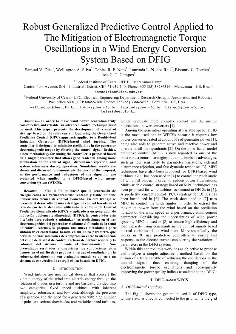
Simulation results are obtained using a 4-kW DFIG, connected to the power grid (380 V/60 Hz) using a 800-V dc link and a constant rotor speed of 2340 rpm. All simulation tests assume that the wind turbine imposes a constant torque of –17 N.m to the DFIG generator. In order to verify the performance of the rotor current controller, a rms reference current of 7 A is used, while the applied control signal, current response, torque, and power are analyzed. Figs. 5 and 6 show the frequency response to noise attenuation and disturbance rejection, within interval 0 π≤ Ω ≤ , where
sTωΩ = and sT is the sampling time. It can be seen that there is a clear relationship between noise attenuation and disturbance rejection, where higher values of σ improve the disturbance rejection, although the control signal noise is amplified.
Figure 5 – Noise attenuation.
Figure 6 – Disturbance rejection.
The modeling errors can be represented by:
( ) ( )(1 ( ))nG z G z G zδ= + , (23) where nG is the nominal model, considering an upper limit
to the norm of ( )jG eδ Ω given by ( )Gδ Ω in the interval 0 π≤ Ω ≤ .
The closed-loop robust stability is reached if the following condition is satisfied:
( ) ( ) ( )( ) ( )
( ) ( )rR z S z G z
G IS z G z
δΔ +
Ω ≤ Ω = , (24)
where )(ΩrI is defined as the robustness index of the controller.
Figure 7 – Robustness index.
Fig. 7 shows ( )rI Ω for several values of σ when
considering an error of % in the transfer function gain 0b and two-sample delays. Furthermore, the robustness index is virtually the same at low frequencies for all evaluated values of σ , while it can be easily tuned by σ at middle frequencies.
Therefore, the overall analysis of Figs. 5, 6, and 7 denotes that low values of σ improve robustness and noise attenuation, although disturbance rejection performance is seriously affected.
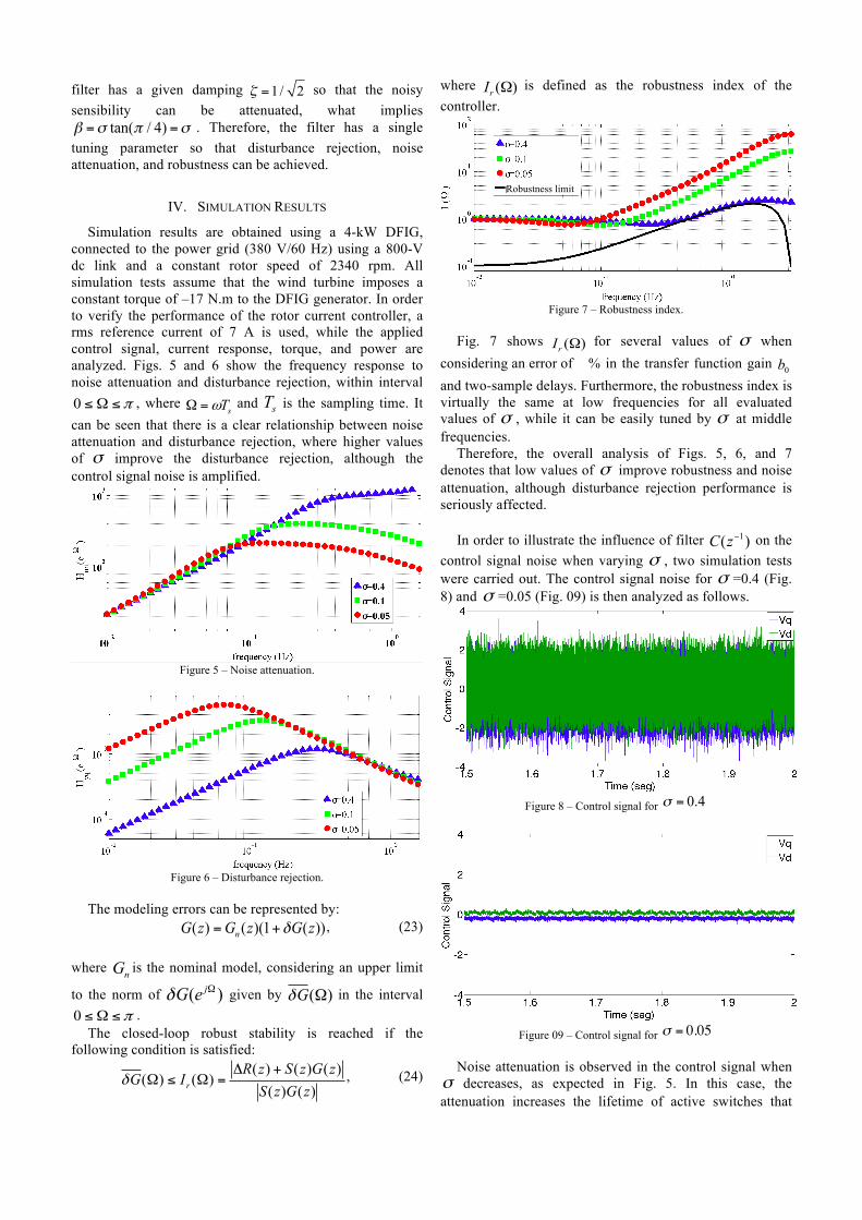
In order to illustrate the influence of filter 1( )C z− on the control signal noise when varying σ , two simulation tests were carried out. The control signal noise for σ =0.4 (Fig. 8) and σ =0.05 (Fig. 09) is then analyzed as follows.
Figure 8 – Control signal for σ = 0.4
Figure 09 – Control signal for σ = 0.05
Noise attenuation is observed in the control signal when
σ decreases, as expected in Fig. 5. In this case, the attenuation increases the lifetime of active switches that
Robustness limit
exist in the power converters due to the reduction of the control signal derivative in abc references. However, σ can not be reduced indefinitely because it affects the disturbance rejection performance directly as seen in Fig. 6.
In order to properly measure the control signal noise attenuation, its respective variance is considered in Eq. (25) so that the results shown in Figs. 8 and 9 can be properly analyzed as in Table II.
( )21var( )
1
n
iiX X
XN
=
−=
−
∑
(25)
where X is a vector which contains N terms and X is the their respective mean value.
TABLE II. Control Signal Variance
Influence of σ
Vq Vd
σ = 0.4 1.2760 1.4209 σ = 0.05 0.0025 0.0025
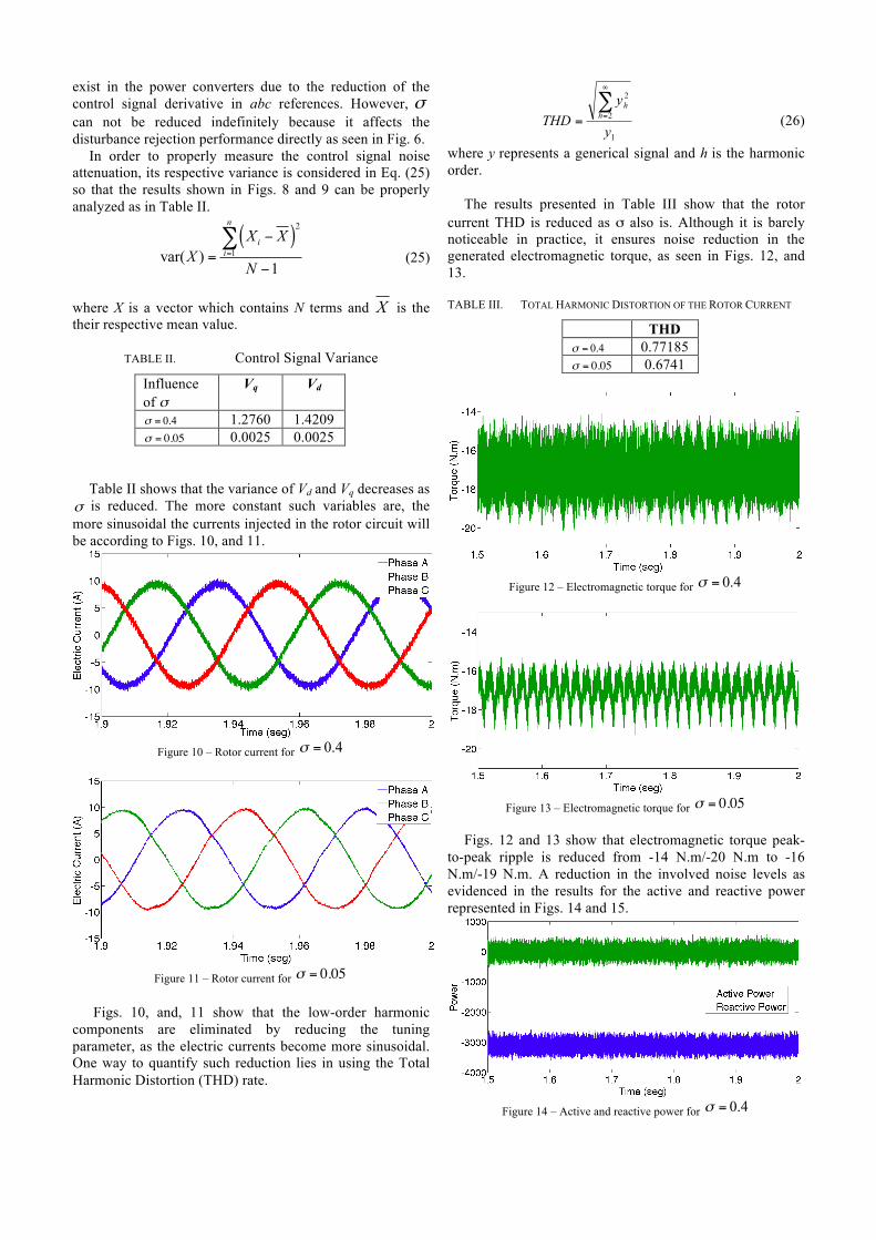
Table II shows that the variance of Vd and Vq decreases as σ is reduced. The more constant such variables are, the more sinusoidal the currents injected in the rotor circuit will be according to Figs. 10, and 11.
Figure 10 – Rotor current for σ = 0.4
Figure 11 – Rotor current for σ = 0.05
Figs. 10, and, 11 show that the low-order harmonic
components are eliminated by reducing the tuning parameter, as the electric currents become more sinusoidal. One way to quantify such reduction lies in using the Total Harmonic Distortion (THD) rate.
1
2
2
y
yTHD h
h∑∞
==
(26)
where y represents a generical signal and h is the harmonic order.
The results presented in Table III show that the rotor current THD is reduced as σ also is. Although it is barely noticeable in practice, it ensures noise reduction in the generated electromagnetic torque, as seen in Figs. 12, and 13.
TABLE III. TOTAL HARMONIC DISTORTION OF THE ROTOR CURRENT
THD σ = 0.4 0.77185 σ = 0.05 0.6741
Figure 12 – Electromagnetic torque for σ = 0.4
Figure 13 – Electromagnetic torque for σ = 0.05
Figs. 12 and 13 show that electromagnetic torque peak-
to-peak ripple is reduced from -14 N.m/-20 N.m to -16 N.m/-19 N.m. A reduction in the involved noise levels as evidenced in the results for the active and reactive power represented in Figs. 14 and 15.
Figure 14 – Active and reactive power for σ = 0.4
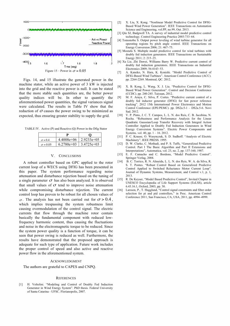
Figure 15 – Power in 05.0=σ
Figs. 14, and 15 illustrate the generated power in the
machine stator, while an active power of 3 kW is injected into the grid and the reactive power is null. It can be stated that the more stable such quantities are, the better power quality indices will be. In other to quantify the aforementioned power quantities, the signal variances signal were calculated. The results in Table IV show that the reduction of σ causes the power swing to be minimized as expected, thus ensuring greater stability to supply the grid.
TABLE IV. Active (P) and Reactive (Q) Power in the Dfig Stator
P Q σ = 0.4 4.4008e+06 2.9233e+05 σ = 0.05 6.2780e+03 3.4725e+03
V. CONCLUSIONS
A robust controller based on GPC applied to the rotor current loop of a WECS using DFIG has been presented in this paper. The system performance regarding noise attenuation and disturbance rejection based on the tuning of a single parameter σ has also been analyzed. It is observed that small values of σ tend to improve noise attenuation while compromising disturbance rejection. The current control loop has proven to be robust for all chosen values of σ . The analysis has not been carried out for 0.4σ > , which implies trespassing the system robustness limit causing overmodulation of the control signal. The electric currents that flow through the machine rotor contain basically the fundamental component with reduced low-frequency harmonic content, thus causing the fluctuations and noise in the electromagnetic torque to be reduced. Since the system power quality is a function of torque, it can be seen that power swing is reduced as well. Furthermore, the results have demonstrated that the proposed approach is adequate for such type of application. Future work includes the proper control of speed and also active and reactive power flow in the aforementioned system.
ACKNOWLEDGMENT The authors are grateful to CAPES and CNPQ.
REFERENCES [1] H. Voltolini. “Modeling and Control of Doubly Fed Induction
Generator in Wind Energy System”. PhD thesis. Federal University of Santa Catarina - UFSC. Florianopolis, 2007.
[2] X. Liu, X. Kong. “Nonlinear Model Predictive Control for DFIG-Based Wind Power Generation”. IEEE Transactions on Automation Science and Engineering, vol.PP, no.99, Out. 2013.
[3] Qin SJ, Badgwell TA. A survey of industrial model predictive control technology. Control Engineering Practice 2003:733–64.
[4] Tomonobu S. Output power leveling of wind turbine generator for all operating regions by pitch angle control. IEEE Transactions on Energy Conversion 2006; 21: 467–75.
[5] Mostafa S. Multiple model predictive control for wind turbines with doubly fed induction generators. IEEE Transactions on Sustainable Energy 2011; 2: 215–25.
[6] Xu Lie, Zhi Dawei, Williams Barry W. Predictive current control of doubly fed induction generators. IEEE Transactions on Industrial Electronics 2009; 56:4143–53.
[7] A. Kaneko, N. Hara, K. Konishi. “Model Predictive Control of DFIG-Based Wind Turbines”. American Control Conference (ACC). pp. 2264-2269. Montreal, QC. 2012.
[8] X. B. Kong, L. Wang, X. J. Liu. “Predictive Control for DFIG-
Based Wind Power Generation”. Control and Decision Conference (CCDC). pp. 240-245. Taiyuan, 2012.
[9] M. F. Araya, C. Silva, P. Cortes. “Predictive current control of a doubly fed inductor generator (DFIG) for fast power reference tracking”. 2012 15th International Power Electronics and Motion Control Conference (EPE/PEMC). pp. DS2a.5-1 – DS2a.5-6. Novi Sad. 2012.
[10] V. P. Pinto, J. C. T. Campos, L. L. N. dos Reis, C. B. Jacobina, N. Rocha. “Robustness and Performance Analysis for the Linear Quadratic Gaussian/Loop Transfer Recovery with Integral Action Controller Applied to Doubly Fed Induction Generators in Wind Energy Conversion Systems”. Electric Power Components and Systems. vol. 40, pp. 1 – 16. 2012.
[11] P. C. Krause, O. Wasynczuk, S. D. Sudhoff. “Analysis of Electric Machinery”. IEEE PRESS. 1995.
[12] D. W. Clarke, C. Mothadi, and P. S. Tuffs, “Generalized Predictive Control. Part I The Basic Algorithm and Part II Extensions and Interpretations”, Automatica, vol. 23, no. 2, pp. 137-160, 1987.
[13] E. F. Camacho and C. Bordons, “Model Predictive Control”. Springer Verlag, 2004.
[14] B. C. Torrico, R. N. Almeida, L. L. N. dos Reis, W. A. da Silva, R. S. T. Pontes. “Robust Control Based on Generalized Predictive Control Applied to Switched Reluctance Motor Current Loop”. Journal of Dynamic Systems, Measurement, and Control v.1, p. 1, 2013.
[15] R. De Keyser, “Model Based Predictive Control”, Invited Chapter in UNESCO Encyclopedia of Life Support Systems (EoLSS), article 6.43.16.1, Oxford, 2003, pp. 30.
[16] Larsson, P., T. Hagglund, “Control signal constraints and filter order selection for pi and pid controllers,” in Proc. American Control Conference 2011, San Francisco, CA, USA, 2011, pp. 4994–4999.