robust yaw stability control of hybrid electric...
TRANSCRIPT

i
ROBUST YAW STABILITY CONTROL OF HYBRID ELECTRIC VEHICLES
MUDHAFAR SALAH KAMIL
A project report submitted in partial fulfilment of the
requirements for the award of the degree of
Master of Engineering (Electrical-Mechatronics and Automatic Control)
Faculty of Electrical Engineering
Universiti Teknologi Malaysia
JUNE 2014

iii
To my parents, my family, wife and children

iv
ACKNOWLEDGEMENT
First and foremost, grateful thanks to Allah S.W.T, god and creator of this
universe for guiding and helping me in the completion of this research project. I
would like to take this precious opportunity to thank my supervisor Dr. Kumaresen
A. Danapalasingam for being a very dedicated supervisor by relentlessly giving me
all the guidance, support and encouragement needed throughout my study.
Besides, very special thanks go to my family; my mother, my wife, and my
children. Thank you all for your continuous prayers, love, kindness, and
encouragement. Finally, I am very thankful to all my friends who help and give
advices to me during all stages of my study. I would like to share my entire honor
with all of you.

v
ABSTRACT
Yaw stability of an automotive vehicle in a various maneuvers is critical to
the overall safety of the vehicle. Robust yaw stability control for a Through-the-Road
Hybrid Electric Vehicle (TtR-HEV) with two in–wheel–motors in rear wheels is
proposed using a Model Predictive control (MPC) controller. The propose technique
aimed to enhance the yaw stability of TtR-HEV, especially on slippery roads to
prevent vehicle from spinning out and provide safety driving under wide range of
driving. This technique based on developed mathematical models of vehicle and
tires. A Model Predictive control (MPC) controller applied to make vehicle yaw rate
to track its reference. The control performance of the proposed yaw stability control
system verified through computer simulation using MATLAB/SIMULINK. The yaw
stability enhanced against uncertainties model, disturbances, and parameter
variations. In addition, better performance achieved by applying the robust control
that is satisfied high effectiveness and robustness.

vi
ABSTRAK
Kestabilan Yaw untuk kenderaan automotif dalam pelbagai jenis manuver
adalah penting untuk keselamatan keseluruhan kenderaan. Kawalan kestabilan Yaw
mantap untuk Through-the-Road Kenderaan Hibrid Elektrik (TtR-HEV) dengan dua
dalam roda motor dalam roda belakang adalah dicadangkan menggunakan Kawalan
Ramalan Model (MPC). Teknik yang dicadangkan adalah bertujuan untuk
meningkatkan kestabilan Yaw untuk TtR-HEV, terutamanya di jalan raya yang licin
untuk mengelakkan kenderaan daripada berpusing keluar dan menyediakan
keselamatan pemandu. Teknik ini adalah berdasarkan model matematik yang
didapatkan daripada kenderaan dan tayar. Kawalan Ramalan Model (MPC)
digunakan untuk membuatkan kadar kenderaan Yaw untuk menjejak isyarat rujukan
kenderaan tersebut. Prestasi sistem kawalan kestabilan Yaw yang dicadangkan
disahkan melalui simulasi komputer menggunakan MATLAB/SIMULINK.
Kestabilan Yaw dapat dipertingkatkan daripada ketidaktentuan model, gangguan,
dan variasi parameter. Di samping itu, prestasi yang lebih baik dicapaikan dengan
menggunakan kawalan yang teguh yang berpuas hati keberkesanan yang tinggi dan
kekukuhan.

vii
TABLE OF CONTENTS
CHAPTER TITLE PAGE
DECLARATION ii
DEDICATION iii
ACKNOWLEDGEMENTS iv
ABSTRACT v
ABSTRAK vi
TABLE OF CONTENTS vii
LIST OF TABLES x
LIST OF FIGURES xi
LIST OF SYMBOLS xiv
LIST OF ABBREVIATIONS xvi
1 INTRODUCTION 1
1.1 Types of Hybrid Electric Vehicle 1
1.1.1 The Series Hybrid Electric Vehicle 2
1.1.2 The Parallel Hybrid Electric Vehicle 3
1.1.2.1 Through-the-Road Hybrid Electric
Vehicle 4
1.1.3 Series-Parallel or Power-Split Hybrid 5
1.2 Yaw Stability 6
1.3 Problem Statement 7
1.4 Objective of Study 7
1.5 Scope of the Project 8
2 LITERATURE REVIEW 9

viii
2.1 Introduction 9
2.2 Types of Stability Control Systems 10
3 METHODOLOGY 14
3.1 Introduction 14
3.2 Research Methodology 15
4 SYSTEM MODEL 18
4.1 Introduction 18
4.2 Tire Dynamic 19
4.3 Vehicle Dynamics for Yaw Motion 20
4.4 Linearized Vehicle Model 25
4.5 Desired Vehicle Model 26
4.6 Model Predictive Control 27
4.7 MPC Strategy 27
4.8 Objective Function 28
4.9 MPC Controller Design 30
5 SIMULATION AND RESULTS 31
5.1 Introduction 31
5.2 Types of Performance Test 32
5.3 J-Turn simulation test 33
5.3.1 Simulation test on wet road condition 33
5.3.2 Simulation test on dry road condition 35
5.4 Single lane-change test 36
5.4.1 Simulation Single lane-change test on wet
road condition 37
5.4.2 Simulation Single lane-change test on dry
road condition 38
5.5 Disturbance Profiles 39
5.5.1 Crosswind Disturbance 39
5.5.2 Braking Torque Disturbance 40
5.5.3 J-Turn simulation test with Crosswind 41

ix
5.5.3.1 J-Turn simulation at velocity 100
km/h with Crosswind Disturbance 41
5.5.3.2 J-Turn simulation at velocity 120
km/h with Crosswind Disturbance 42
5.5.4 J-Turn simulation with Braking Torque
Disturbance 43
5.5.4.1 J-Turn simulation at velocity 100
km/h with Braking Torque
Disturbance
43
5.5.5 Single lane-change Simulation with
Crosswind Disturbance test 46
5.5.5.1 Single lane-change simulation at
velocity 100 km/h with Crosswind
Disturbance
46
5.5.5.2 Single lane-change simulation at
velocity 120 km/h with Crosswind
Disturbance
47
5.5.6 Simulation Single lane-change with Braking
Torque Disturbance test 48
5.5.6.1 Single lane-change simulation at
velocity 100 km/h with Braking
Torque Disturbance
48
5.5.6.2 Single lane-change simulation at
velocity 120 km/h with Braking
Torque Disturbance
49
6 CONCLUSION AND RECOMENDATION 52
6.1 Conclusion 52
6.2 Recommendation 53
REFERENCES

x
LIST OF TABLES
TABLE NO. TITLE PAGE
3.1 Adhesion coefficient on different road conditions 17
5.1 Parameters of the vehicle 51
5.2 Simulation test types 51

xi
LIST OF FIGURES
FIGURE NO. TITLE PAGE
1.1 Configuration of a series hybrid electric vehicle 3
1.2 Configuration of a parallel hybrid electric vehicle 4
1.3 Configuration of a powertrain for a TtR-HEV 5
1.4 Configuration of a series-parallel hybrid or a power-split
drivetrain 5
1.5 The functioning of a yaw stability control system 6
2.1 Schematic of a TtR-HEV 10
3.1 Research methodology flow chart 15
4.1 One wheel vehicle model 20
4.2 Illustration of moving vehicle, indicated by its body
coordinate frame B in a global coordinate frame G 21
4.3 Top view to show the yaw angle and sideslip angle 21
4.4 Vehicle model for yaw dynamics 22
4.5 Single-track model for vehicle 24
4.6 Considered control structure 30
5.1 Simulink of yaw stability control 32
5.2 Steering angle for a J-turn 34
5.3 Yaw rate in J-Turn input steer ( μ=0.4) 34
5.4 Sideslip angle in J-Turn input steer ( μ=0.4) 35
5.5 Yaw rate in J-Turn input steer ( μ=0.7) 35
5.6 Sideslip angle in J-Turn input steer ( μ=0.7) 36
5.7 Steering angle for a single lane-change 36
5.8 Yaw rate in single lane change 37
xii
5.9 Sideslip angle in single lane change 37
5.10 Yaw rate in single lane change ( μ=0.7) 38
5.11 Sideslip angle in single lane change ( μ=0.7) 38
5.12 Simulation block diagram with crosswind disturbance 39
5.13 Crosswind disturbance 40
5.14 Braking torque disturbance 40
5.15 Yaw rate in J-Turn test with crosswind disturbance at
vehicle velocity 100 km/h 41
5.16 Sideslip angle in J-Turn test with crosswind disturbance
at vehicle velocity 100 km/h 42
5.17 Yaw rate in J-Turn test with crosswind disturbance at
vehicle velocity 120 km/h 42
5.18 Sideslip angle in J-Turn test with crosswind disturbance
at vehicle velocity 120 km/h 43
5.19 Yaw rate in J-Turn test with braking torque disturbance
at vehicle velocity 100 km/h 44
5.20 sideslip angle in J-Turn test with braking torque
disturbance at vehicle velocity 100 km/h 44
5.21 Yaw rate in J-Turn test with braking torque disturbance
at vehicle velocity 120 km/h 45
5.22 sideslip angle in J-Turn test with braking torque
disturbance at vehicle velocity 120 km/h 45
5.23 Yaw rate in single lane change with crosswind
disturbance at vehicle velocity 100 km/h 46
5.24 Sideslip angle in single lane change with crosswind
disturbance at vehicle velocity 100 km/h 47
5.25 Yaw rate in single lane change with crosswind
disturbance at vehicle velocity 120 km/h 47
5.26 Sideslip angle in single lane change with crosswind
disturbance at vehicle velocity 120 km/h 48
5.27 Yaw rate in single lane change with braking torque
disturbance at vehicle velocity 100 km/h 49
5.28 Sideslip angle in single lane change with braking torque 49

xiii
disturbance at vehicle velocity 100 km/h
5.29 Yaw rate in single lane change with braking torque
disturbance at vehicle velocity 120 km/h 50
5.30 Sideslip angle in single lane change with braking torque
disturbance at vehicle velocity 120 km/h 50

xiv
LIST OF SYMBOLS
- Wheel steering angle (in degree)
- Braking torque at ith
wheel (in newton meters)
- Vehicle velocity at centre of gravity (in kilometers per hour)
- Vehicle side slip angle (in degree)
- Desired vehicle side slip angle (in degree)
As - Steering stability factor
- Vehicle yaw rate (in degree per second)
- Desired vehicle yaw rate (in degree per second)
- Sideslip angle at ith
wheel (in degree)
- Tyre rotational speed at ith
wheel (in revolutions per minute)
- Longitudinal tyre force at ith
wheel (in newtons)
- Lateral tyre force at ith
Wheel (in newtons)
Mz - Yaw moment (in newton meters)
- Nominal tyre cornering stiffness at front wheel (in newtons per
radian)
- Nominal tyre cornering stiffness at front wheel (in newtons per
radian)
- Distance from the vehicle center of gravity to the front axle (in
meters)
- Distance from the vehicle center of gravity to the rear axle (in
meters)
- Moment of inertia of vehicle body (in kilogram square meters)
- Gravitational acceleration = 9.81 (in meters per second squared)
Mz - Yaw moment (in newton meters)
m - Total mass of the vehicle (in kilograms)

xv
μ - Tire–road friction coefficient
P - Predication horizon (intervals)
M - Control horizon (intervals)
u(k) - Input vector
Δu - Predicted change in control value
r(k) - Setpoint
y(k) - Predicted output
x(k) - Vector of state variable
Q(i) - Output error weight matrix
R(i) - Control weight matrix

xvi
LIST OF ABBREAVIATIONS
ABS - Anti-Lock Braking System
ASC - Active Steering Control
CG - Center of Gravity
DOF - Degree of Freedom
DYC - Direct Yaw Moment Control
ESP - Electronic Stability Program
FWS - Front Wheels Steering
HEV - Hybrid Electric Vehicle
ICE - Internal Combustion Engine
ISM - Integral Sliding Mode
IWM - In-Wheel-Motor
LPV - Linear Parameter Varying
LQR - Linear Quadratic Regulator
MIMO - Multi Input Multi Output
MPC - Model Predictive Control
PID - Proportional Integration Derivative
SA-DOB - Steering angle-disturbance Observer
SISO - Single Input Single Output
SMC - Sliding Mode Control
TCS - Traction Control System
TtR - Through-the-Road
VSC - Vehicle Stability Control
VTD - Variable Torque Distribution
YMO - Yaw Moment Observer

1
CHAPTER 1
INTRODUCTION
1.1 Types of Hybrid Electric Vehicle
A hybrid electric vehicle is one that has two or main sources of
propulsion power. They have both internal combustion engine and one or more
electric motors and can be driven by either powertrain or together sources
simultaneously.
Recently, hybrid electric vehicle (HEV) have been developed very
rapidly as a solution of energy problems, as well as environmental global
warming issues. Compared to an internal combustion engine vehicles, a hybrid
electric vehicle (HEV) can help reduce polluting emissions and can also offer
highly reduced fuel consumption [1]. Thus, it has become the most available in
technology and a great concern of researchers in this field.
HEV have evident advantages over conventional internal combustion
engine vehicles. Firstly, a quick, accurate and comprehensible torque response.
Secondly, output torque can be easily measured from motor current. Thirdly
electric motors which are fixed in each wheel can be independently controlled.

2
HEV can be classified according to hybrid architectures. The most
common architectures are parallel, series, and combination parallel-series
hybrid electric vehicles. The resulting configurations can be treated under the
following general categories:
1.1.1 The Series Hybrid Electric Vehicle
In the series hybrid electric vehicle, where uses the electric motor to drive the
vehicle and this provides all the propulsion power. The internal combustion engine
(ICE) directly connected to an electric generator or alternator. The principal
advantage of this configuration is that series hybrid vehicle typically used in heavy-
duty vehicles such as trucks, buses and other urban vehicles involved in a lot of stop-
and-go driving. The system also reduces the need for conventional transmissions and
clutches. This architecture has high efficiency and has very low emissions. The
inefficiency associated with series hybrid, it is much low efficiency during high
speed driving, due to losses in converting the mechanical power from the ICE to
electricity and in charging and discharging of the battery as well as it also requires a
large and heavy battery pack, which lead to increases cost and reduces vehicle
performance from the weight of the batteries. The series hybrid architecture is
depicted in Figure 1.1.

3
Figure 1.1 Configuration of a series hybrid electric vehicle [2].
1.1.2 The Parallel Hybrid Electric Vehicle
The parallel hybrid uses a motor or more and an engine to powered the
wheels of the hybrid electric vehicle together. The engine and motors are both
connected directly to the drive train (see Figure 1.2). The main advantages of parallel
architecture over a series architecture are generator is not required as well as the
traction motor is smaller and light battery. Thus, this can minimizes the additional
cost of the motor and battery pack. But the control of the parallel hybrid drive train is
more complicated than a series, due to the mechanical coupling between the engine
and the driven wheels.
Parallel-hybrid vehicles can be further divided into two categories according
to the location of the electric motors. First category, the engine-assist systems,
secondly, known as a through-the-road hybrid. In this research will be design robust
yaw stability control of through-the-road hybrid electric vehicle (TtR-HEV).
4
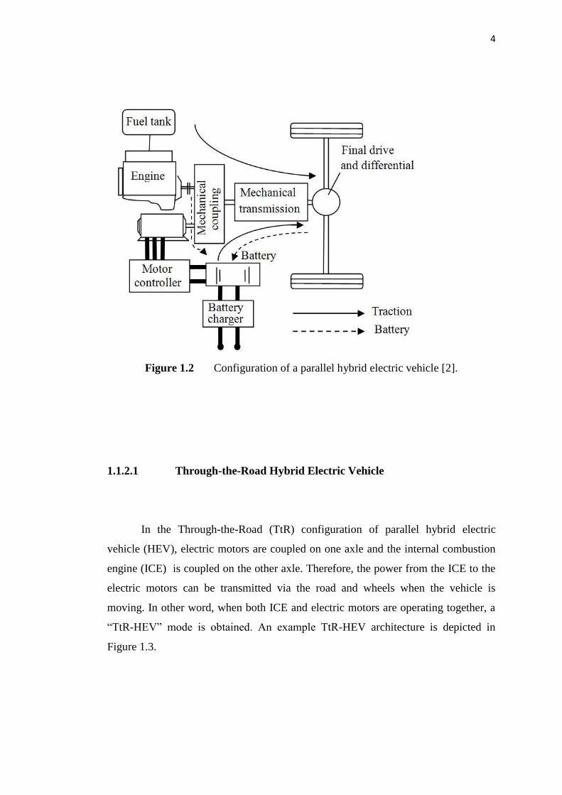
Figure 1.2 Configuration of a parallel hybrid electric vehicle [2].
1.1.2.1 Through-the-Road Hybrid Electric Vehicle
In the Through-the-Road (TtR) configuration of parallel hybrid electric
vehicle (HEV), electric motors are coupled on one axle and the internal combustion
engine (ICE) is coupled on the other axle. Therefore, the power from the ICE to the
electric motors can be transmitted via the road and wheels when the vehicle is
moving. In other word, when both ICE and electric motors are operating together, a
“TtR-HEV” mode is obtained. An example TtR-HEV architecture is depicted in
Figure 1.3.

5
Figure 1.3 Configuration of a powertrain for a TtR-HEV.
1.1.3 Series-Parallel or Power-Split Hybrid
The series-parallel hybrid included usefulness and the construction of the
series and parallel drive trains. By consolidating the two configurations, the ICE can
be used to propulsion specifically wheels (as in the parallel drive train) and likewise
be enough discontinued from the wheels so that only the electric motor propels the
wheels (as in the series drive train). As a result of this new design, the ICE works at
near optimum efficiency frequently. This framework is more costly because of the
more complex hardware. In any case, the series-parallel hybrid has the possibility to
fulfill better than either of the series or parallel hybrid systems alone. The
configuration of a series-parallel hybrid drivetrain is shown in Figure 1.4.
Figure 1.4 Configuration of a series-parallel hybrid or a power-split drivetrain
[2].

6
1.2 Yaw Stability
Stability control systems that prevent automotive vehicle from skidding and
spinning out are often referred to as yaw stability control systems [2]. Yaw stability
of hybrid electric vehicle in a cornering situation is critical to vehicle stability and
handling performance. Yaw stability aims to improve safety by keeping the vehicle
yaw rate following its target commanded by the driver and keeping the vehicle slip
angle in a small range (see Figure 1.5). In other words, yaw stability ensures a
vehicle does not spin uncontrollably during emergency maneuvers and in critical
driving conditions.
Figure 1.5 The functioning of a yaw stability control system [2].

7
1.3 Problem Statement
A study done by Ackermann (1997) found that the yaw rate of the automotive
vehicle is not only stirred by lateral acceleration in a way that the driver is used to,
but also by disturbance torques resulting for example when a car encounters
unexpected road conditions, such as a split-μ road, the tire slip angles. So, the vehicle
slip angle may suddenly increase, which causes the vehicle to reach its physical limit
of adhesion between the tires and the road. The driver has to compensate this
disturbance torque by opposing at the steering wheel in order to provide disturbance
reduction. This is the more hard task for the driver because the disturbance input
comes as an abruptness to him; since most drivers have less experience operating a
vehicle under this situation, they might at last lose control of the vehicle [30].
Accordingly vehicle yaw stability ensures a car does not spin uncontrollably
during emergency maneuvers and in critical driving conditions. This capability is
especially needed when a car makes a sharp or high speed turn along a slippery road.
Useful articles, researches and studies have been written about robust yaw stability
control of hybrid electric vehicles, but there is little research has been done of TtR-
HEV. With the above problem statement established, it is obvious to state that it is
highly significant to design a robust yaw stability control of Through-the-Road
Hybrid Electric Vehicle (TtR-HEV).

8
1.4 Objective of Study
The objective of this research are as follows:
(a.) To develop a single-track TtR-HEV model
(b.) To design a controller that is satisfy the robust yaw stability of a TtR-HEV.
(c.) To simulate and evaluate the performance of the system with a proposed
controller.
1.5 Scope of the Project
This study focuses on the system that is Through-the-Road Hybrid Electric
Vehicle (TtR-HEV), which contains the internal combustion engine (ICE) mounted
on the front axle and two in-wheel-motors for rear traction. The work undertaken in
this project are limited to the following aspects:
(a.) Mathematical model of the TtR-HEV is developed of a single track car
model.
(b.) A controller will be designed to maintain the yaw stability of TtR-
HEV based on mathematical models of vehicle and tires using MPC
control technique.
(c.) Perform a simulation works by using MATLAB/SIMULINK to
observe effectiveness and robustness of the controller.

i

REFERENCES
1. Ehsani, M., Gao, Y. and Emadi, A. (2009). Modern Electric, Hybrid Electric,
and Fuel Cell Vehicles: Fundamentals, Theory, and Design. Florida: CRC
press.
2. Rajamani, R. (2012). Vehicle Dynamics and Control. New York: Springer US.
3. Kim, D., Hwang, S. and Kim, H. (2008). Vehicle Stability Enhancement of
Four-Wheel-Drive Hybrid Electric Vehicle Using Rear Motor
Control. Vehicular Technology, IEEE Transactions. 57(2), 727-735.
4. Geng, C., Mostefai, L., Denaï, M. and Hori, Y. (2009). Direct Yaw-Moment
Control of An In-Wheel Motored Electric Vehicle Based on Body Slip Angle
Fuzzy Observer. Industrial Electronics, IEEE Transactions. 56(5), 1411-1419.
5. Kim, J., Park, C., Hwang, S., Hori, Y. and Kim, H. (2010). Control Algorithm
for An Independent Motor-Drive Vehicle. Vehicular Technology, IEEE
Transactions. 9(7), 3213-3222.
6. Nam, K., Oh, S., Fujimoto, H. and Hori, Y. (2012). Design of Adaptive
Sliding Mode Controller for Robust Yaw Stabilization of In-wheel Motor-
driven Electric Vehicles. International Battery, Hybrid and Fuel Cell Electric
Vehicle Symposium. 6 – 9 May, Los Angeles, California: EVS26,1-3.
7. Zhou, H. and Liu, Z. (2010). Vehicle Yaw Stability Control System Design
Based on Sliding Mode and Backstepping Control Approach. Vehicular
Technology, IEEE Transactions. 59(7), 3674-3678.
8. Canale, M., Fagiano, L., Ferrara, A. and Vecchio, C. (2008). Vehicle Yaw
Control Via Second-Order Sliding-Mode Technique. Industrial Electronics,
IEEE Transactions. 55(11), 3908-3916.
9. Guvenc, B. A., Guvenc, L. and Karaman, S. (2009). Robust Yaw Stability
Controller Design and Hardware-in-the-Loop Testing for A Road
Vehicle. Vehicular Technology, IEEE Transactions. 58(2), 555-571.

10. Ancha, S., Baviskar, A., Wagner, J. R. and Dawson, D. M. (2007). Ground
Vehicle Steering Systems: Modelling, Control, and Analysis of Hydraulic,
Electric and Steer-by-Wire Configurations. International journal of vehicle
design. 44(1), 188-208.
11. Nam, K., Oh, S., Fujimoto, H. and Hori, Y. (2012). Robust Yaw Stability
Control for Electric Vehicles Based on Active Front Steering Control
Through A Steer-by-Wire System. International Journal of Automotive
Technology. 13(7), 1169-1176.
12. Guvenc, B. A., Bunte, T., Odenthal, D. And Guvenc, L. (2004). Robust Two
Degree-of-Freedom Vehicle Steering Controller Design. Control Systems
Technology, IEEE Transactions. 12(4), 627-636.
13. Guo, L. and Hui, W. (2011). A Study on the Control System of the Vehicle
Steering Stability. IEEE International Conference. 19-22 August, Jilin, China:
IEEE, 2027-2030.
14. Zhang, Z., Liu, Z., Liu, X. and Huang, C. (2013). Observe-Based Direct
Yaw-Moment H∞ Control for In-Wheel Motored Electric Vehicle. Journal of
Theoretical & Applied Information Technology.49(2).
15. Mpetshi, D. and Delprat, S. (2012). Robust Yaw Motion Controller for
Improving the Stability of A Plug-in Hybrid Vehicle. IEEE American Control
Conference (ACC). 27-29 June, Montréal, Canada: IEEE, 6527-6532.
16. Cheong, J., Eom, W. and Lee, J. (2009). Cornering Stability Improvement for
4 Wheel Drive Hybrid Electric Vehicle. IEEE International Symposium. 5-8
July, Seoul Olympic Parktel, Seoul, Korea: IEEE, 853-858.
17. Bünte, T., Odenthal, D., Aksun-Güvenç, B. and Güvenç, L. (2002). Robust
Vehicle Steering Control Design Based on the Disturbance Observer. Annual
reviews in control. 26(1), 139-149.
18. Lin, C. and Peng, C. L. (2013). Mixed H∞/H2 Output Feedback Stability
Control for Dual-Motor Independent Drive Electric Vehicle. Advanced
Materials Research. 658, 602-608.
19. Crolla, D. A. and Cao, D. (2012). The Impact of Hybrid and Electric
Powertrains on Vehicle Dynamics, Control Systems and Energy
Regeneration. Vehicle system dynamics. 50(sup1), 95-109.

20. Guvenc, B. A. and Guvenc, L. (2002). Robust Steer-by-Wire Control Based
on the Model Regulator. Proceedings of the 2002 IEEE International
Conference. 18-20 September, Glasgow, Scotland, U.K.: IEEE, 435-440.
21. Furukawa, Y., Yuhara, N., Sano, S., Takeda, H. and Matsushita, Y. (1989).
A Review of Four-Wheel Steering Studies From the Viewpoint of Vehicle
Dynamics and Control. Vehicle System Dynamics. 18(1-3), 151-186.
22. Hirano, Y. and Fukatani, K. (1996). Development of Robust Active Rear
Steering Control. Proceedings of the International Symposium on Advanced
Vehicle Control AVEC. June, Susono-shi, Sizuoka-ken, JAPAN: AVEC, 359-
376.
23. Rong-hui, Z., Guo-ying, C., Guo-qiang, W., Hong-guang, J. and Tao, C.
(2007). Robust Optimal Control Technology for Four-wheel Steering Vehicle.
IEEE International Conference. 5-8 August, JAPAN: IEEE, 1513-1517.
24. Wheals, J. C., BAKER, H., RAMSEY, K. and Turner, W. (2004). Torque
Vectoring Awd Driveline: Design, Simulation, Capabilities and Control. SAE
transactions. 113(6), 557-576.
25. Saeks, R., Cox, C. J., Neidhoefer, J., Mays, P. R. and Murray, J. J. (2002).
Adaptive Control of A Hybrid Electric Vehicle. Intelligent Transportation
Systems, IEEE Transactions on. 3(4), 213-234.
26. Dash, B. K. and Subudhi, B. (2013). A Fuzzy Adaptive Sliding Mode Slip
Ratio Controller of a HEV. IEEE International Conference. 7-10 July, India:
IEEE, 1-8.
27. Kodagoda, K. R. S., Wijesoma, W. S. and Teoh, E. K. (2002). Fuzzy Speed
and Steering Control of An AGV. Control Systems Technology, IEEE
Transactions. 10(1), 112-120.
28. Liu, Q., Kaiser, G., Boonto, S., Werner, H., Holzmann, F., Chretien, B. and
Korte, M. (2011). Two-Degree-of-Freedom LPV Control for A Through-the-
Road Hybrid Electric Vehicle Via Torque Vectoring. 50th IEEE Conference.
12-15 December, Orlando, FL, USA: IEEE, 274-1279.
29. Fujimoto, H., Takahashi, N., Tsumasaka, A. and Noguchi, T. (2006). Motion
Control of Electric Vehicle Based on Cornering Stiffness Estimation With
Yaw-moment Observer. 9th IEEE International Workshop. March, Istanbul,
Turkey: IEEE, 206-211.

30. Ackermann, J. (1997). Robust Control Prevents Car Skidding. Control
Systems, IEEE. 17(3), 23-31.
31. Camacho, E. F. and Bordons, C. (2004). Model Predictive Control. London:
Springer.
32. Orukpe, P. E. (2005). Basics of Model Predictive Control. Master degree of
Science in Control Engineering, Imperial College, London.
33. Tyagunov, A. A. (2004). High-Performance Model Predictive Control for
Process Industry. Ph.D. degree of Science in Control system, Faculty of
Electrical Engineering, Eindhoven University of Technology.
34. Langson, W., Chryssochoos, I., Rakovic, S. V. and Mayne, D. Q. (2004).
Robust model predictive control using tubes. Automatica. 40, 125–133.
35. Kothare, M. V., Balakrishnan, V. and Morari, M. (1996). Robust constrained
model predictive control using linear matrix inequalities. Automatica. 32(10),
1361–1379.