rochester carb 4 bbl adjustement 94hg5c
TRANSCRIPT
5
C
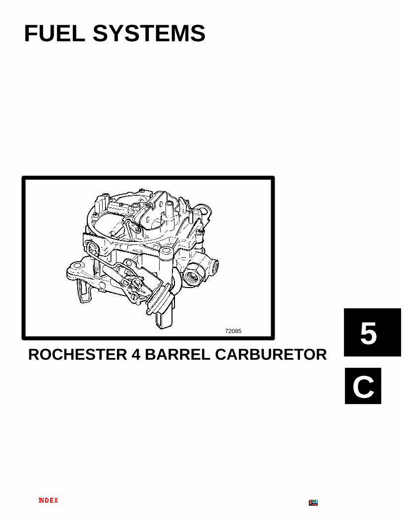
72085
FUEL SYSTEMS
ROCHESTER 4 BARREL CARBURETOR
5C-0 - ROCHESTER 4 BARREL CARBURETOR 90-806535940 893
Table of ContentsPage
Rochester 4 Barrel Carburetor 5C-1. . . . . . . . . . . . . Torque Specifications 5C-1. . . . . . . . . . . . . . . . . . Tools 5C-1. . . . . . . . . . . . . . . . . . . . . . . . . . . . . . . . . Specifications 5C-2. . . . . . . . . . . . . . . . . . . . . . . . . Identification 5C-2. . . . . . . . . . . . . . . . . . . . . . . . . . Fuel Filter 5C-2. . . . . . . . . . . . . . . . . . . . . . . . . . . .
Exploded View 5C-3. . . . . . . . . . . . . . . . . . . . . . . . . . . Adjustments 5C-4. . . . . . . . . . . . . . . . . . . . . . . . . . . . .
Accelerator Pump 5C-4. . . . . . . . . . . . . . . . . . . . . Air Valve Dashpot 5C-5. . . . . . . . . . . . . . . . . . . . . . Air Valve Spring Windup 5C-5. . . . . . . . . . . . . . . . Float Level 5C-6. . . . . . . . . . . . . . . . . . . . . . . . . . . . Choke Coil Rod 5C-6. . . . . . . . . . . . . . . . . . . . . . . Vacuum Break 5C-7. . . . . . . . . . . . . . . . . . . . . . . . Float Weight 5C-8. . . . . . . . . . . . . . . . . . . . . . . . . . Float Level Adjustments 5C-8. . . . . . . . . . . . . . . . Preliminary Idle Speed and Mixture 5C-10. . . . . Final Idle Speed and Mixture 5C-10. . . . . . . . . . .
5C - ROCHESTER 4 BARREL CARBURETOR
ROCHESTER 4 BARREL CARBURETOR - 5C-190-806535940 893
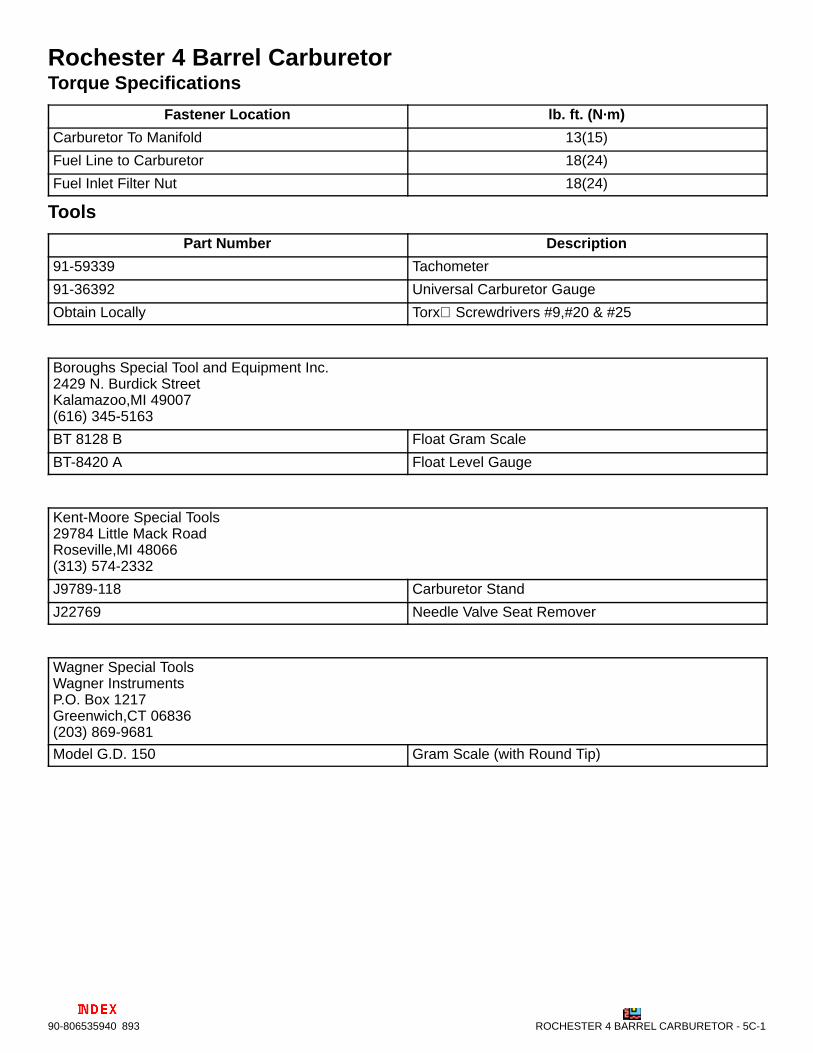
Rochester 4 Barrel CarburetorTorque Specifications
Fastener Location lb. ft. (N·m)
Carburetor To Manifold 13(15)
Fuel Line to Carburetor 18(24)
Fuel Inlet Filter Nut 18(24)
Tools
Part Number Description
91-59339 Tachometer
91-36392 Universal Carburetor Gauge
Obtain Locally Torx Screwdrivers #9,#20 & #25
Boroughs Special Tool and Equipment Inc.2429 N. Burdick StreetKalamazoo,MI 49007(616) 345-5163
BT 8128 B Float Gram Scale
BT-8420 A Float Level Gauge
Kent-Moore Special Tools 29784 Little Mack Road Roseville,MI 48066(313) 574-2332
J9789-118 Carburetor Stand
J22769 Needle Valve Seat Remover
Wagner Special Tools Wagner InstrumentsP.O. Box 1217Greenwich,CT 06836(203) 869-9681
Model G.D. 150 Gram Scale (with Round Tip)
5C-2 - ROCHESTER 4 BARREL CARBURETOR 90-806535940 893
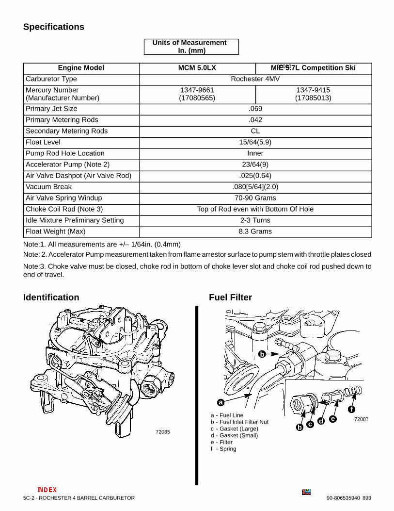
Specifications
00000
Units of Measurement In. (mm)
Engine Model MCM 5.0LX MIE 5.7L Competition Ski
Carburetor Type Rochester 4MV
Mercury Number(Manufacturer Number)
1347-9661(17080565)
1347-9415(17085013)
Primary Jet Size .069
Primary Metering Rods .042
Secondary Metering Rods CL
Float Level 15/64(5.9)
Pump Rod Hole Location Inner
Accelerator Pump (Note 2) 23/64(9)
Air Valve Dashpot (Air Valve Rod) .025(0.64)
Vacuum Break .080[5/64](2.0)
Air Valve Spring Windup 70-90 Grams
Choke Coil Rod (Note 3) Top of Rod even with Bottom Of Hole
Idle Mixture Preliminary Setting 2-3 Turns
Float Weight (Max) 8.3 Grams
Note:1. All measurements are +/– 1/64in. (0.4mm)Note: 2. Accelerator Pump measurement taken from flame arrestor surface to pump stem with throttle plates closed
Note:3. Choke valve must be closed, choke rod in bottom of choke lever slot and choke coil rod pushed down toend of travel.
Identification
72085
Fuel Filter
72087a - Fuel Lineb - Fuel Inlet Filter Nutc - Gasket (Large)d - Gasket (Small)e - Filterf - Spring
b c
af
b
d e
ROCHESTER 4 BARREL CARBURETOR - 5C-390-806535940 893
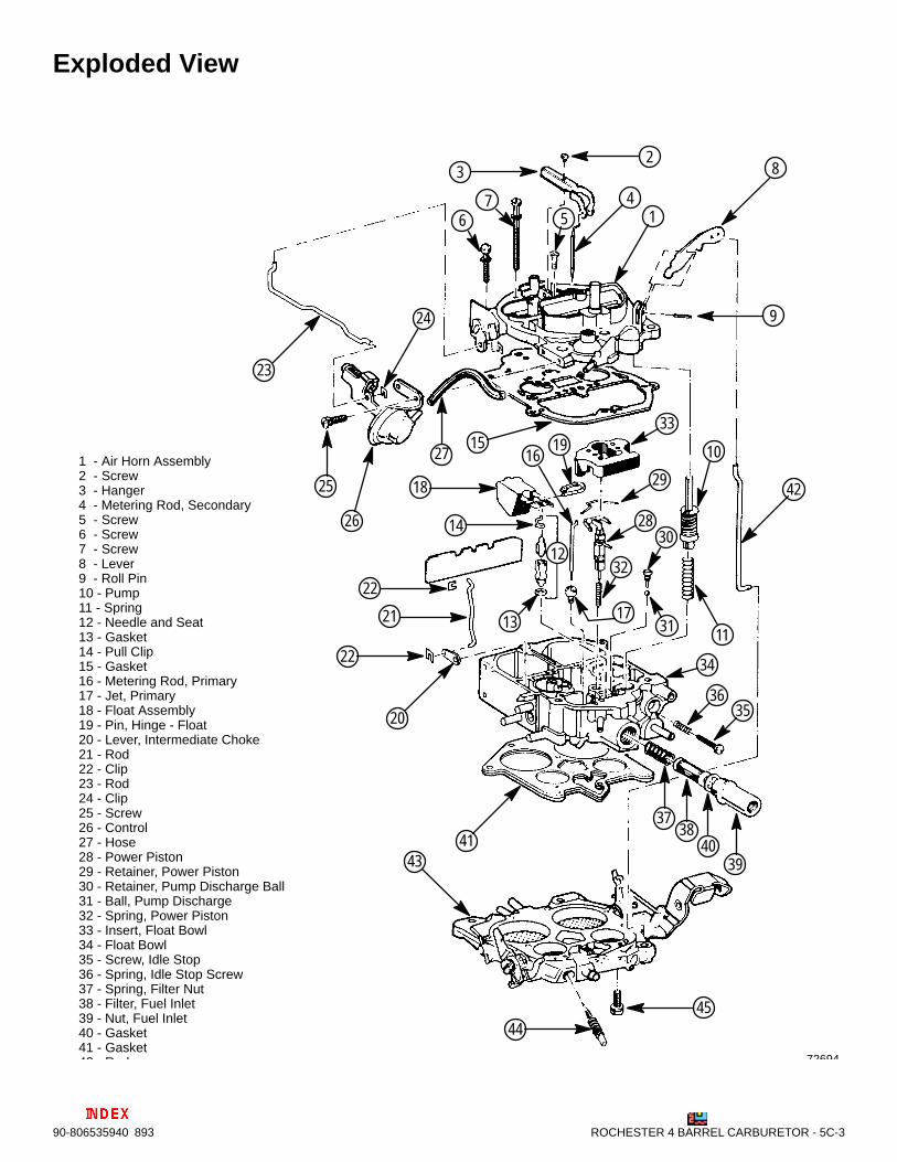
Exploded View
72694
1 - Air Horn Assembly2 - Screw3 - Hanger4 - Metering Rod, Secondary5 - Screw6 - Screw7 - Screw8 - Lever9 - Roll Pin10 - Pump11 - Spring12 - Needle and Seat13 - Gasket14 - Pull Clip15 - Gasket16 - Metering Rod, Primary17 - Jet, Primary18 - Float Assembly19 - Pin, Hinge - Float20 - Lever, Intermediate Choke21 - Rod22 - Clip23 - Rod24 - Clip25 - Screw26 - Control27 - Hose28 - Power Piston29 - Retainer, Power Piston30 - Retainer, Pump Discharge Ball31 - Ball, Pump Discharge32 - Spring, Power Piston33 - Insert, Float Bowl34 - Float Bowl35 - Screw, Idle Stop36 - Spring, Idle Stop Screw37 - Spring, Filter Nut38 - Filter, Fuel Inlet39 - Nut, Fuel Inlet40 - Gasket41 - Gasket42 Rod
1
3
456
7
8
10
11
12
13
14
1516
17
18
19
20
22
24
25
26
29
30
31
32
33
34
3536
37
27
28
38
394041
42
43
4445
2
9
21
23
22
5C-4 - ROCHESTER 4 BARREL CARBURETOR 90-806535940 893
Adjustments! WARNING
Avoid gasoline fire or explosion. Improper instal-lation of brass fittings or plugs into fuel pump orfuel filter base can crack casting and/or cause afuel leak .
• Apply #592 Loctite Pipe Sealant with Teflon tothreads of brass fitting or plug. DO NOT USETEFLON TAPE.
• Thread brass fitting or plug into fuel pump orfuel filter base until finger tight.
• Tighten fitting or plug an additional 1-3/4 to2-1/4 turns using a wrench. DO NOT OVER-TIGHTEN.
• Install fuel line. To prevent over-tightening,hold brass fitting with suitable wrench andtighten fuel line connectors securely.
• Check for fuel leaks.
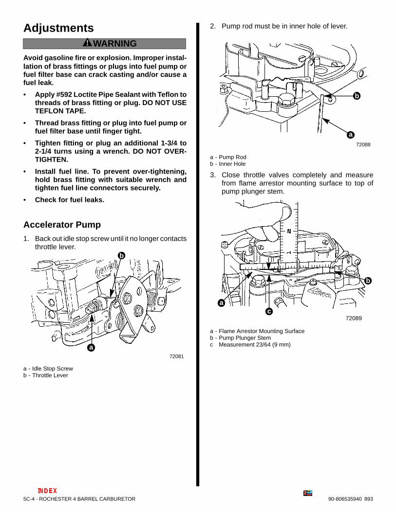
Accelerator Pump1. Back out idle stop screw until it no longer contacts
throttle lever.
72081
b
a
a - Idle Stop Screwb - Throttle Lever
2. Pump rod must be in inner hole of lever.
72088
b
a
a - Pump Rodb - Inner Hole
3. Close throttle valves completely and measurefrom flame arrestor mounting surface to top ofpump plunger stem.
72089
b
ca
a - Flame Arrestor Mounting Surfaceb - Pump Plunger Stemc Measurement 23/64 (9 mm)
ROCHESTER 4 BARREL CARBURETOR - 5C-590-806535940 893
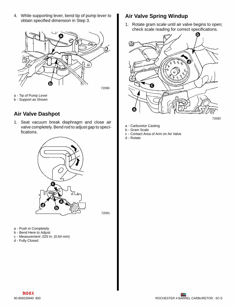
4. While supporting lever, bend tip of pump lever toobtain specified dimension in Step 3.
72090b
a
a - Tip of Pump Leverb - Support as Shown
Air Valve Dashpot1. Seat vacuum break diaphragm and close air
valve completely. Bend rod to adjust gap to speci-fications.
72091
b
c
ad
a - Push in Completelyb - Bend Here to Adjustc - Measurement .025 In. (0.64 mm)d - Fully Closed
Air Valve Spring Windup1. Rotate gram scale until air valve begins to open;
check scale reading for correct specifications.
72092
b
c
d
a
a - Carburetor Castingb - Gram Scalec - Contact Area of Arm on Air Valved - Rotate
5C-6 - ROCHESTER 4 BARREL CARBURETOR 90-806535940 893
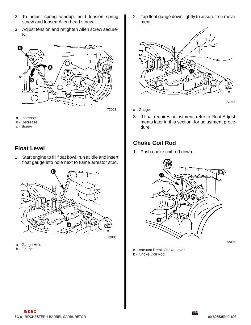
2. To adjust spring windup, hold tension springscrew and loosen Allen head screw.
3. Adjust tension and retighten Allen screw secure-ly.
72093
a - Increaseb - Decreasec - Screw
b
c
a
Float Level1. Start engine to fill float bowl, run at idle and insert
float gauge into hole next to flame arrestor stud.
72083
a - Gauge Holeb - Gauge
b
a
2. Tap float gauge down lightly to assure free move-ment.
72082
a
a - Gauge
3. If float requires adjustment, refer to Float Adjust-ments later in this section, for adjustment proce-dure.
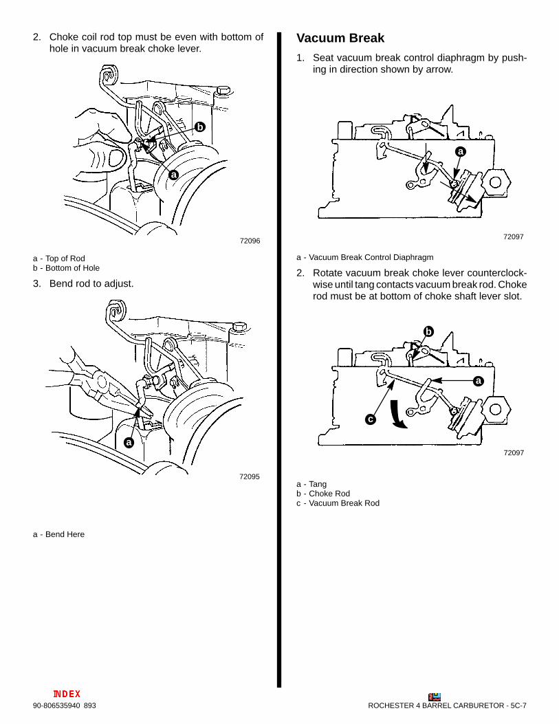
Choke Coil Rod1. Push choke coil rod down.
72096
b
a
a - Vacuum Break Choke Leverb - Choke Coil Rod
ROCHESTER 4 BARREL CARBURETOR - 5C-790-806535940 893
2. Choke coil rod top must be even with bottom ofhole in vacuum break choke lever.
72096
b
a
a - Top of Rodb - Bottom of Hole
3. Bend rod to adjust.
72095
a
a - Bend Here
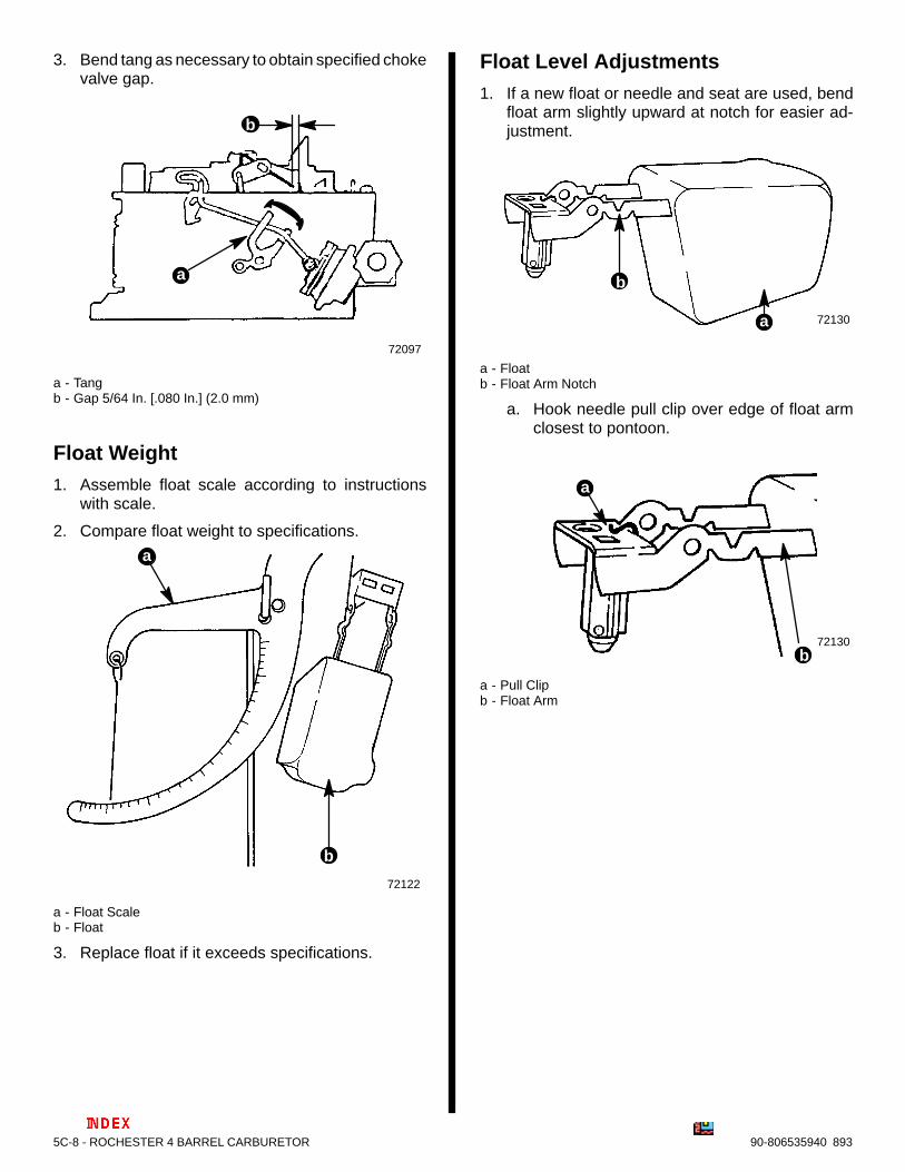
Vacuum Break1. Seat vacuum break control diaphragm by push-
ing in direction shown by arrow.
72097
a
a - Vacuum Break Control Diaphragm
2. Rotate vacuum break choke lever counterclock-wise until tang contacts vacuum break rod. Chokerod must be at bottom of choke shaft lever slot.
72097
c
a
b
a - Tangb - Choke Rodc - Vacuum Break Rod
5C-8 - ROCHESTER 4 BARREL CARBURETOR 90-806535940 893
3. Bend tang as necessary to obtain specified chokevalve gap.
72097
b
a
a - Tangb - Gap 5/64 In. [.080 In.] (2.0 mm)
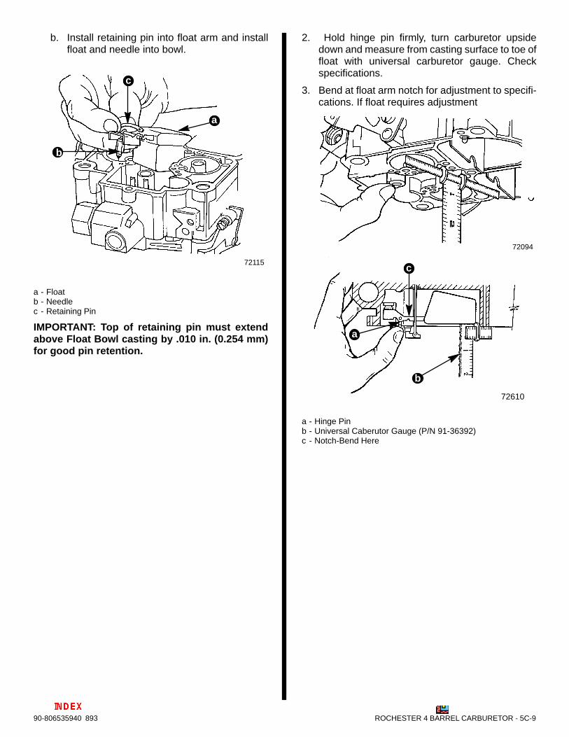
Float Weight1. Assemble float scale according to instructions
with scale.
2. Compare float weight to specifications.
72122
b
a
a - Float Scaleb - Float
3. Replace float if it exceeds specifications.
Float Level Adjustments1. If a new float or needle and seat are used, bend
float arm slightly upward at notch for easier ad-justment.
72130a
b
a - Floatb - Float Arm Notch
a. Hook needle pull clip over edge of float armclosest to pontoon.
72130b
a
a - Pull Clipb - Float Arm
ROCHESTER 4 BARREL CARBURETOR - 5C-990-806535940 893
b. Install retaining pin into float arm and installfloat and needle into bowl.
72115
b
c
a
a - Floatb - Needlec - Retaining Pin
IMPORTANT: Top of retaining pin must extendabove Float Bowl casting by .010 in. (0.254 mm)for good pin retention.
2. Hold hinge pin firmly, turn carburetor upsidedown and measure from casting surface to toe offloat with universal carburetor gauge. Checkspecifications.
3. Bend at float arm notch for adjustment to specifi-cations. If float requires adjustment
72094
b
c
a
72610
a - Hinge Pinb - Universal Caberutor Gauge (P/N 91-36392)c - Notch-Bend Here
5C-10 - ROCHESTER 4 BARREL CARBURETOR 90-806535940 893
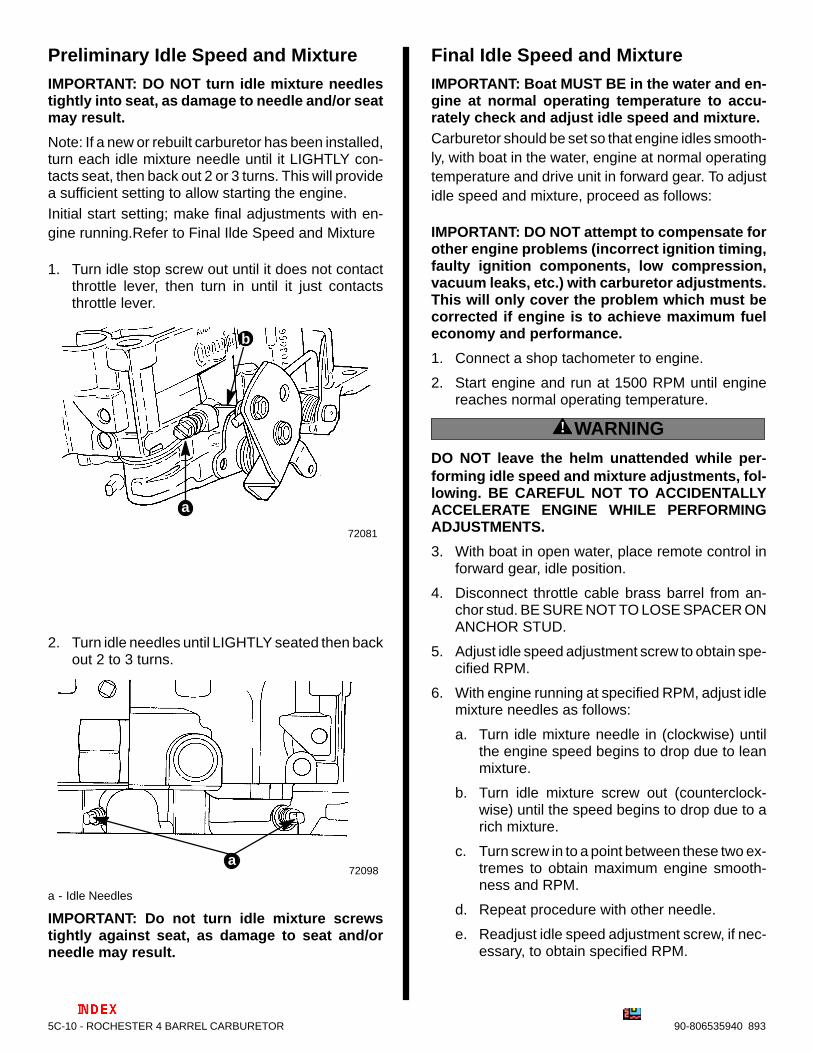
Preliminary Idle Speed and MixtureIMPORTANT: DO NOT turn idle mixture needlestightly into seat, as damage to needle and/or seatmay result.
Note: If a new or rebuilt carburetor has been installed,turn each idle mixture needle until it LIGHTLY con-tacts seat, then back out 2 or 3 turns. This will providea sufficient setting to allow starting the engine.Initial start setting; make final adjustments with en-gine running.Refer to Final Ilde Speed and Mixture
1. Turn idle stop screw out until it does not contactthrottle lever, then turn in until it just contactsthrottle lever.
72081
b
a
2. Turn idle needles until LIGHTLY seated then backout 2 to 3 turns.
72098a
a - Idle Needles
IMPORTANT: Do not turn idle mixture screwstightly against seat, as damage to seat and/orneedle may result.
Final Idle Speed and MixtureIMPORTANT: Boat MUST BE in the water and en-gine at normal operating temperature to accu-rately check and adjust idle speed and mixture.Carburetor should be set so that engine idles smooth-ly, with boat in the water, engine at normal operatingtemperature and drive unit in forward gear. To adjustidle speed and mixture, proceed as follows:
IMPORTANT: DO NOT attempt to compensate forother engine problems (incorrect ignition timing,faulty ignition components, low compression,vacuum leaks, etc.) with carburetor adjustments.This will only cover the problem which must becorrected if engine is to achieve maximum fueleconomy and performance.
1. Connect a shop tachometer to engine.
2. Start engine and run at 1500 RPM until enginereaches normal operating temperature.
! WARNING
DO NOT leave the helm unattended while per-forming idle speed and mixture adjustments, fol-lowing. BE CAREFUL NOT TO ACCIDENTALLYACCELERATE ENGINE WHILE PERFORMINGADJUSTMENTS.
3. With boat in open water, place remote control inforward gear, idle position.
4. Disconnect throttle cable brass barrel from an-chor stud. BE SURE NOT TO LOSE SPACER ONANCHOR STUD.
5. Adjust idle speed adjustment screw to obtain spe-cified RPM.
6. With engine running at specified RPM, adjust idlemixture needles as follows:
a. Turn idle mixture needle in (clockwise) untilthe engine speed begins to drop due to leanmixture.
b. Turn idle mixture screw out (counterclock-wise) until the speed begins to drop due to arich mixture.
c. Turn screw in to a point between these two ex-tremes to obtain maximum engine smooth-ness and RPM.
d. Repeat procedure with other needle.
e. Readjust idle speed adjustment screw, if nec-essary, to obtain specified RPM.