rock exotica az vortex - rescue 3 exotica az vortex multipod arizona vortex 2004 ropes that rescue...
TRANSCRIPT
MULArizona
Vortex
2004 Ropes That Rescue Ltd Seminar, Australia
UUsseerr MMaannuu727002.00.031705
RRoocckk EExxoottiicca
aAZ VORTEX
TIPODaall
AZV Multipod USERS MANUAL
Arizona
Vortex
2
s,
. Tripod (conventional and “easel” leg) nd “sideways”)
Key Improvements incorporated into the Multipod:
• Lighter, shorter legs (without any loss of tripod height) are easier to transport much
•
Introduction
Congratulations on your purchase of the AZ VORTEX MULTIPOD from Rock Exotica! This beautiful, handcrafted piece of equipment will serve your artificial high directional (AHD) needs for years to come. You have chosen the most versatile and state of the art AHD available to rescuers and industry workers today. With proper study and hands-on training, you may use the Multipod in a variety of ways and in any number of environments from industry to wilderness.
The Multipod is ideal for most edge-mitigation applications including confined space entry, as well as mine, cliff and industrial rescue operations. It is also well suited for bridge and dam inspection, rope access, construction trades, military and the movie industry.
The new Multipod is the next evolution of the Arizona Vortex. Named the “Multipod” because of its flexibility, the two-piece head can be rigged as a standard tripod, or in advanced applications as an A-frame, a sideways A-frame, or a Gin Pole. The “easel” leg allows the tripod to be leaned to form an easel A-frame in order to position the change of direction pulley closer to the edge of the cliff or the structure.
With the adjustable leg lengths and the flexible third leg, the Multipod lets rescuers set up an artificial high directional in virtually any urban, industrial or wilderness location. The telescoping legs also project through the Head Set providing a wide range of adjustment. The lighter Head Set and the lighter, shorter legs make the Multipod easier to transport and store.
On the A-frame and easel A-frame application, at least two pulleys can now be attached directly into the Head Set without carabiners, eliminating lost headspace and working clearance. This two pulley capability makes the Multipod ideal for use with high lines and track line offsets. For rope access work, it allows the use of two Working Lines.
What is the AZV MULTIPOD?
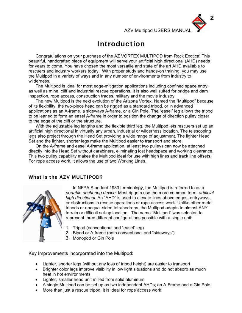
In NFPA Standard 1983 terminology, the Multipod is referred to as a portable anchoring device. Most riggers use the more common term, artificial high directional. An “AHD” is used to elevate lines above edges, entrywayor obstructions in rescue operations or rope access work. Unlike other metal tripods or unequal-sided tetrahedrons, the Multipod adapts to almost ANY terrain or difficult set-up location. The name “Multipod” was selected to represent three different configurations possible with a single unit: 12. Bipod or A-frame (both conventional a3. Monopod or Gin Pole
• Brighter color legs improve visibility in low light situations and do not absorb asheat in hot environments
milled from solid aluminum HDs; an A-Frame and a Gin Pole
Lighter, smaller head unit • A single Multipod can be set up as two independent A• More than just a rescue tripod, it is ideal for rope access work
AZV Multipod USERS MANUAL
Arizona
Vortex
3
he
lat Foot. This design works well on flat surfaces such as floors, roadways, or
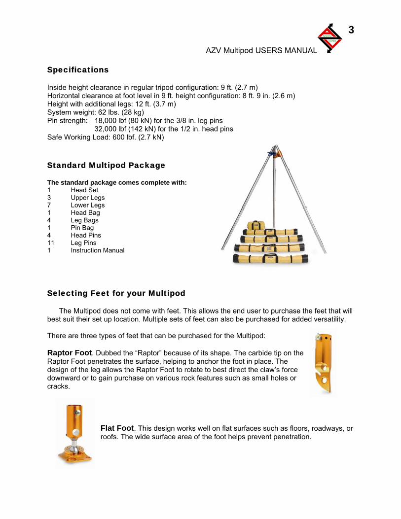
Specifications Inside height clearance in regular tripod configuration: 9 ft. (2.7 m) Horizontal clearance at foot level in 9 ft. height configuration: 8 ft. 9 in. (2.6 m) Height with additional legs: 12 ft. (3.7 m) System weight: 62 lbs. (28 kg) Pin strength: 18,000 lbf (80 kN) for the 3/8 in. leg pins 32,000 lbf (142 kN) for the 1/2 in. head pins Safe Working Load: 600 lbf. (2.7 kN) Standard Multipod Package The standard package comes complete with: 1 Head Set 3 Upper Legs 7 Lower Legs 1 Head Bag 4 Leg Bags 1 Pin Bag 4 Head Pins 11 Leg Pins 1 Instruction Manual Selecting Feet for your Multipod
The Multipod does not come with feet. This allows the end user to purchase the feet that will
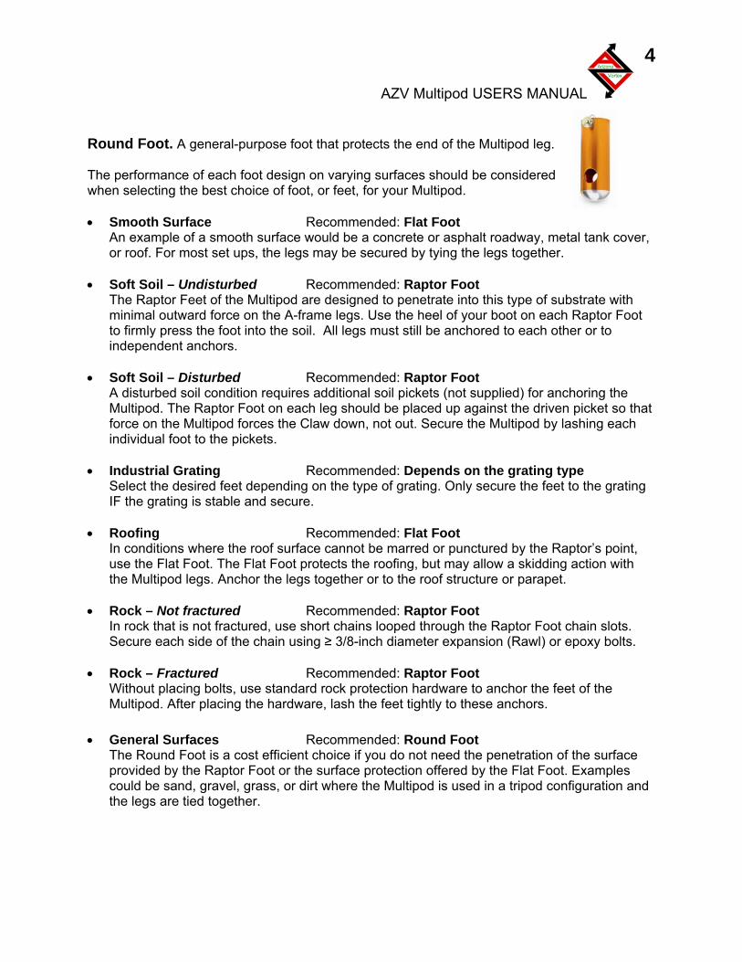
best suit their set up location. Multiple sets of feet can also be purchased for added versatility. There are three types of feet that can be purchased for the Multipod: Raptor Foot. Dubbed the “Raptor” because of its shape. The carbide tip on tRaptor Foot penetrates the surface, helping to anchor the foot in place. The design of the leg allows the Raptor Foot to rotate to best direct the claw’s force downward or to gain purchase on various rock features such as small holes or cracks.
Froofs. The wide surface area of the foot helps prevent penetration.
AZV Multipod USERS MANUAL
Arizona
Vortex
4
ound Foot. A general-purpose foot that protects the end of the Multipod leg.
he performance of each foot design on varying surfaces should be considered
Smooth Surface Recommended: Flat Foot alt roadway, metal tank cover,
Soft Soil – Undisturbed Recommended: Raptor Foot
is type of substrate with t
Soft Soil – Disturbed Recommended: Raptor Foot
require plied) for anchoring the at
• dustrial Grating Recommended: Depends on the grating type et depending e grating
• ofing Recommended: Flat Foot ns where the roof surfa ctured by the Raptor’s point,
• ock – Not fractured Recommended: Raptor Foot Raptor Foot chain slots.
• ock – Fractured Recommended: Raptor Foot , use standa anchor the feet of the
• General Surfaces Recommen Round Foot cost efficien enetration of the surface
d
R Twhen selecting the best choice of foot, or feet, for your Multipod. •
An example of a smooth surface would be a concrete or asphor roof. For most set ups, the legs may be secured by tying the legs together.
•The Raptor Feet of the Multipod are designed to penetrate into thminimal outward force on the A-frame legs. Use the heel of your boot on each Raptor Footo firmly press the foot into the soil. All legs must still be anchored to each other or to independent anchors.
•A disturbed soil condition s additional soil pickets (not supMultipod. The Raptor Foot on each leg should be placed up against the driven picket so thforce on the Multipod forces the Claw down, not out. Secure the Multipod by lashing each individual foot to the pickets. InSelect the desired fe on the type of grating. Only secure the feet to thIF the grating is stable and secure. RoIn conditio ce cannot be marred or punuse the Flat Foot. The Flat Foot protects the roofing, but may allow a skidding action with the Multipod legs. Anchor the legs together or to the roof structure or parapet. RIn rock that is not fractured, use short chains looped through the Secure each side of the chain using ≥ 3/8-inch diameter expansion (Rawl) or epoxy bolts. RWithout placing bolts rd rock protection hardware to Multipod. After placing the hardware, lash the feet tightly to these anchors.
ded:
The Round Foot is a t choice if you do not need the pprovided by the Raptor Foot or the surface protection offered by the Flat Foot. Examples could be sand, gravel, grass, or dirt where the Multipod is used in a tripod configuration anthe legs are tied together.
AZV Multipod USERS MANUAL
Arizona
Vortex
5
WARNINGS When performing rescue, climbing or work within the vertical realm, the risk of injury or death cannot be eliminated. Do not use this device unless you have: • Read all the instructions and warnings • Received competent and suitable training • Trained your entire team on the proper use of this device • Checked the Multipod and rigging equipment before each use • Accept total responsibility for your safety and the equipment suitability/configuration. TRAINING AND EXPERIENCE IN TECHNICAL RIGGING IS ESSENTIAL FOR SAFE USE! This device can topple over if the user does not properly account for the direction and the strength of forces occurring in the specific situation and configuration. It is the user’s responsibility to read and understand the user manual accompanying this device. However, this manual is not intended to teach you everything you need to know to use this device safely. • Do not exceed the safe working load of 600 lbf (2.7 kN) • Always maintain a second Safety Line independent of this device • All feet on this device must be securely anchored to resist sideways, spreading and uplift
forces • Do not couple more than three (3) lower leg sections together on any one leg
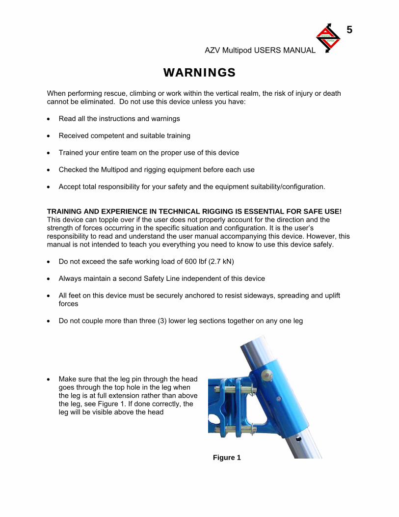
Figure 1
• Make sure that the leg pin through the head goes through the top hole in the leg when the leg is at full extension rather than above the leg, see Figure 1. If done correctly, the leg will be visible above the head
AZV Multipod USERS MANUAL
Arizona
Vortex
6
he
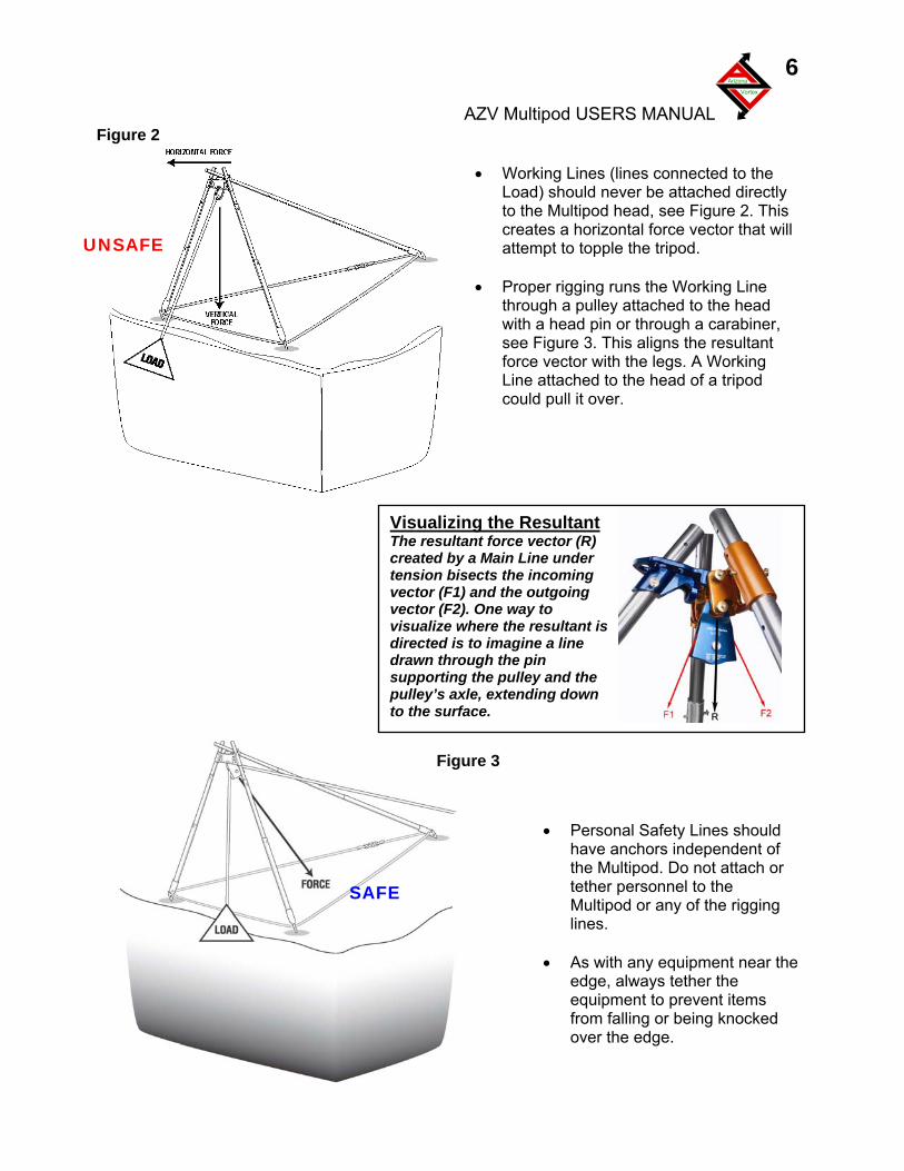
• Working Lines (lines connected to the
Load) should never be attached directly to the Multipod head, see Figure 2. This creates a horizontal force vector that will attempt to topple the tripod.
• Proper rigging runs the Working Line
through a pulley attached to the head with a head pin or through a carabiner, see Figure 3. This aligns the resultant force vector with the legs. A Working Line attached to the head of a tripod could pull it over.
• Personal Safety Lines should
have anchors independent of the Multipod. Do not attach or tether personnel to the Multipod or any of the rigging lines.
• As with any equipment near t
edge, always tether the equipment to prevent items from falling or being knocked over the edge.
UNSAFE
SAFE
Visualizing the Resultant The resultant force vector (R) created by a Main Line under tension bisects the incoming vector (F1) and the outgoing vector (F2). One way to visualize where the resultant is directed is to imagine a line drawn through the pin supporting the pulley and the pulley’s axle, extending down to the surface.
Figure 3
Figure 2
AZV Multipod USERS MANUAL
Arizona
Vortex
7
Principles of Operation Stability is always a concern when using tripods, A-frames, and Gin Poles. Unless the forces are carefully evaluated, the possibility of legs slipping or the structure toppling is very real. The following Principles of Operation apply to using the Multipod as well as other tripods, A-frames, and Gin Poles. • Whenever possible, set up the Multipod in the three-legged configuration. It usually takes
less effort to transport the complete set of legs than to securely rig the Multipod in the A-frame or Gin Pole configuration. An A-frame and a Gin Pole provide options where the full tripod configuration cannot be adapted to the location.
• The resultant force on any tripod should be directly down, as close to the center of the three
legs as possible. • When extending the easel leg of the Multipod, the resultant force vector may move toward
the A-frame legs and a tag line will be necessary to stabilize the Multipod. Connect the tag line between one of the triangular holes in the head and secure it to an anchor behind the Multipod.
• The resultant force on an A-frame should be in line with the legs. A line projected through
the pin and pulley axle should be aligned with the legs. The angles between the Working Line and the legs on either side should be equal.
• Do not exceed the safe working load. As an artificial high directional, the Multipod uses a
change of direction pulley at the head. Depending on the entry and exit angle of the Working Line, the force on the legs can be multiplied to twice the weight of the load.
• Prevent any possible movement of the legs by connecting the feet together with rope,
webbing, or chain, or by anchoring each individual foot to the surface. • Consider using the easel leg to the side when setting up sideways A-frame. If the Working
Line is kept inside the legs, stability is increased. The easel leg should still be guyed back. • 8 or 9 mm Accessory Cord works well for Guy Lines and Tether Cords in most
circumstances. Use the triangular holes in the head for attaching Guy Lines. • Always run the Safety Line (Belay Line) at ground level. This minimizes the possible fall
distance if the AHD topples or collapses. • Always provide travel restraint for personnel working near the edge.
AZV Multipod USERS MANUAL
Arizona
Vortex
8
Using the Multipod
Assembly of the Multipod
It takes at least two people to assemble the Multipod and is easier with more. Installing the Multipod at ANY edge without handrails requires the use of Travel Restraint within the Hazard Zone. There are two ways to assemble the Multipod: 1) Build in place. This allows easier movement but individual sections must be supported and belayed until the assembly is complete. Assemble as much as possible, such as each head piece to a leg, before moving into positions. 2) Build it away from the edge and then walk it out as one piece to the edge. This may require three to four people to move it into place but only requires a single Tether Line for safety.
Sometimes a combination of both ways work well but remember that it is difficult to change pins at the head while standing on an edge by a large drop. Make these changes back from the edge and then move the Multipod into position and tie down the feet only after making your final changes. Several attempts at getting it right may be needed before tie down commences. This process will become less cumbersome with experience.
Each method has advantages and disadvantages depending on the location and the
available personnel. Practicing both will prepare the team to select the best option under difficult set up positions.
Always attach a Tether Cord to the individual sections or to the entire unit until the Multipod
is secured. Tether Cords should be belayed on a separate anchor to prevent the Multipod from toppling over during installation. The Tether Cords can be left in place during the operation for later disassembly. Never leave an unsecured Multipod unattended.
Support each leg section until the unit is secured to prevent toppling during set up. As in any
rigging situation, one person should be in charge of the set up and communication should be deliberate and precise.
Disassembly of the Multipod
Disassembly of the Multipod is less problematic. With adequate personnel on travel restraint devices, remove the anchoring at each foot and carry the entire device back out of the hazard zone for disassembly. Again, the Tether Cord should be in place during this movement away from the edge. Once the Multipod is well away from any hazard, it may be taken apart, inspected for any damage, and stowed in its proper storage compartments. (Some teams initially tie brightly colored ribbon around all of the pins to make them easy to spot on the ground).
AZV Multipod USERS MANUAL
Arizona
Vortex
9
ecured ated
Anchoring the Multipod
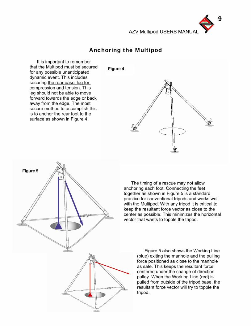
It is important to remember
that the Multipod must be sfor any possible unanticipdynamic event. This includes securing the rear easel leg for compression and tension. This leg should not be able to move forward towards the edge or back away from the edge. The mossecure method to accomplish this is to anchor the rear foot to the surface as shown in Figure 4.
t
The timing of a rescue may not allow
ancd
ell
al
igure 5 also shows the Working Line (blu
e
horing each foot. Connecting the feet together as shown in Figure 5 is a standarpractice for conventional tripods and works wwith the Multipod. With any tripod it is critical to keep the resultant force vector as close to the center as possible. This minimizes the horizontvector that wants to topple the tripod.
F
Figure 5
Figure 4
e) exiting the manhole and the pulling force positioned as close to the manhole as safe. This keeps the resultant force centered under the change of direction pulley. When the Working Line (red) is pulled from outside of the tripod base, thresultant force vector will try to topple the tripod.
AZV Multipod USERS MANUAL
Arizona
Vortex
10
Note on the Raptor Foot
g
ripod
When you connect the Raptor Foot to the leg, position it so that the force exerted on the lepushes the tip of the foot towards the center of the tor bipod. This encourages the “claw” to bite into the surface.
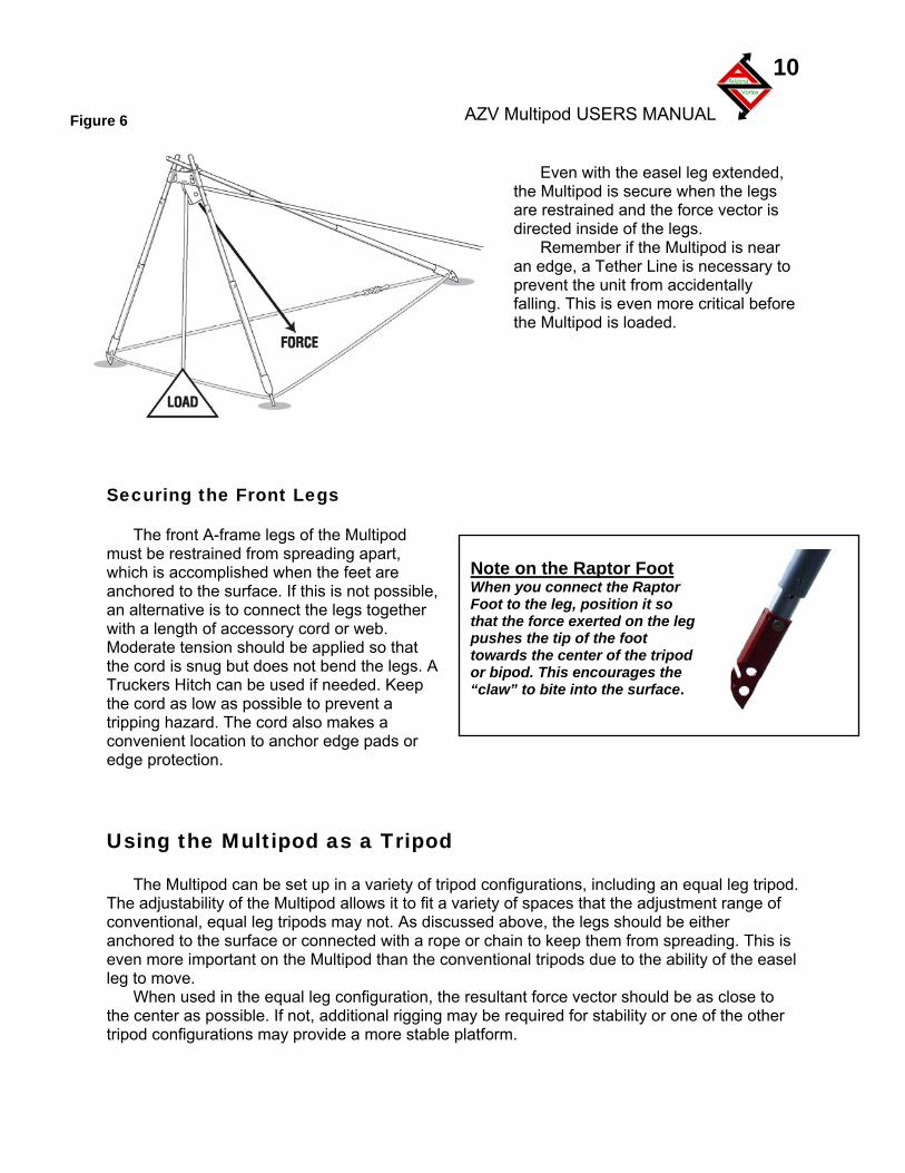
Even with the easel leg extended,
the
d is near an
fore
ecuring the Front Legs
The front A-frame legs of the Multipod mu
ible,
hat A
or
sing the Multipod as a Tripod
The Multipod can be set up in a variety of tripod configurations, including an equal leg tripod. The
This is
d in the equal leg configuration, the resultant force vector should be as close to the
Figure 6
Multipod is secure when the legs are restrained and the force vector is directed inside of the legs.
Remember if the Multipoedge, a Tether Line is necessary to
prevent the unit from accidentally falling. This is even more critical bethe Multipod is loaded.
S
st be restrained from spreading apart, which is accomplished when the feet are anchored to the surface. If this is not possan alternative is to connect the legs together with a length of accessory cord or web. Moderate tension should be applied so tthe cord is snug but does not bend the legs. Truckers Hitch can be used if needed. Keep the cord as low as possible to prevent a tripping hazard. The cord also makes a convenient location to anchor edge padsedge protection.
U
adjustability of the Multipod allows it to fit a variety of spaces that the adjustment range of conventional, equal leg tripods may not. As discussed above, the legs should be either anchored to the surface or connected with a rope or chain to keep them from spreading.even more important on the Multipod than the conventional tripods due to the ability of the easel leg to move.
When use center as possible. If not, additional rigging may be required for stability or one of the other
tripod configurations may provide a more stable platform.
AZV Multipod USERS MANUAL
Arizona
Vortex
11
ripod Set Up with
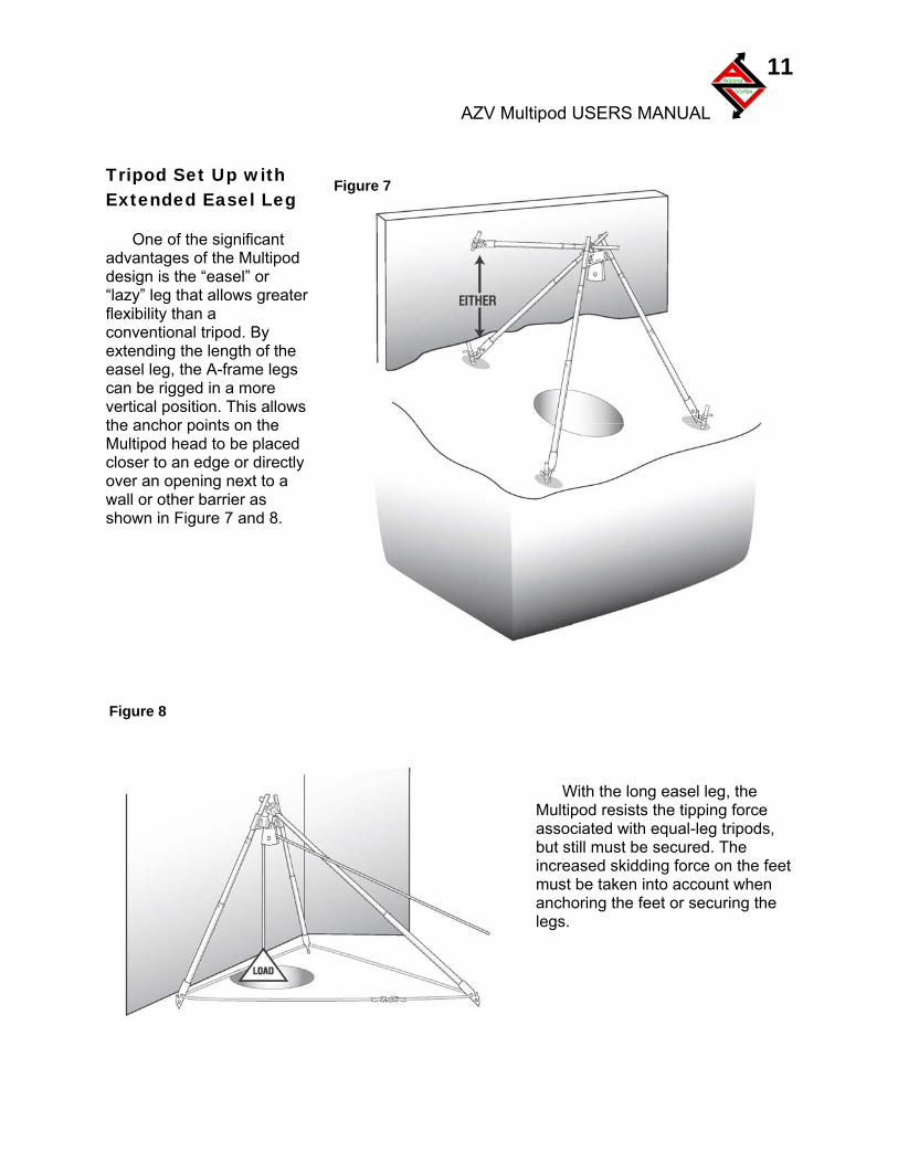
One of the significant advantages of the Multipod
ater
od. By he
ws
d
.
TExtended Easel Leg
design is the “easel” or “lazy” leg that allows greflexibility than a conventional tripextending the length of teasel leg, the A-frame legs can be rigged in a more vertical position. This allothe anchor points on the Multipod head to be placecloser to an edge or directly over an opening next to a wall or other barrier as shown in Figure 7 and 8
With the long easel leg, the Multipod resists the tipping force associated with equal-leg tripods, but still must be secured. The increased skidding force on the feet must be taken into account when anchoring the feet or securing the legs.
igure 8
Figure 7
F
AZV Multipod USERS MANUAL
Arizona
Vortex
12
Using the Multipod
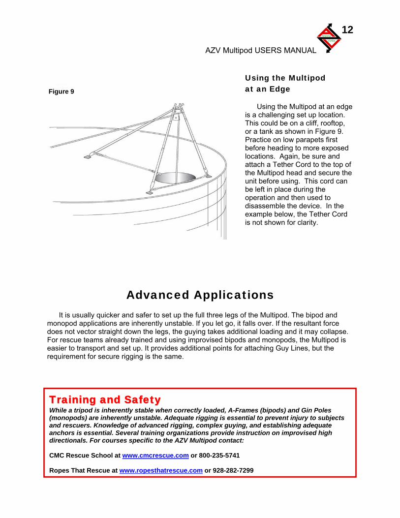
Figure 9 at an Edge
Using the Multipod at an edge is a challenging set up location. This could be on a cliff, rooftop, or a tank as shown in Figure 9. Practice on low parapets first before heading to more exposed locations. Again, be sure and attach a Tether Cord to the top of the Multipod head and secure the unit before using. This cord can be left in place during the operation and then used to disassemble the device. In the example below, the Tether Cord is not shown for clarity.
Advanced Applications
It is usually quicker and safer to set up the full three legs of the Multipod. The bipod and monopod applications are inherently unstable. If you let go, it falls over. If the resultant force does not vector straight down the legs, the guying takes additional loading and it may collapse. For rescue teams already trained and using improvised bipods and monopods, the Multipod is easier to transport and set up. It provides additional points for attaching Guy Lines, but the requirement for secure rigging is the same.
TTrraaiinniinngg aanndd SSaaffeettyy While a tripod is inherently stable when correctly loaded, A-Frames (bipods) and Gin Poles (monopods) are inherently unstable. Adequate rigging is essential to prevent injury to subjects and rescuers. Knowledge of advanced rigging, complex guying, and establishing adequate anchors is essential. Several training organizations provide instruction on improvised high directionals. For courses specific to the AZV Multipod contact: CMC Rescue School at www.cmcrescue.com or 800-235-5741 Ropes That Rescue at www.ropesthatrescue.com or 928-282-7299
AZV Multipod USERS MANUAL
Arizona
Vortex
13
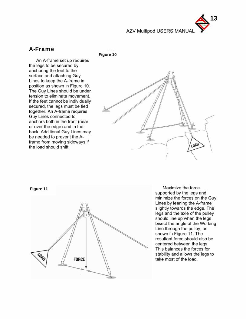
Figure 10 A-Frame
An A-frame set up requires the legs to be secured by anchoring the feet to the surface and attaching Guy Lines to keep the A-frame in position as shown in Figure 10. The Guy Lines should be under tension to eliminate movement. If the feet cannot be individually secured, the legs must be tied together. An A-frame requires Guy Lines connected to anchors both in the front (near or over the edge) and in the back. Additional Guy Lines may be needed to prevent the A-frame from moving sideways if the load should shift.
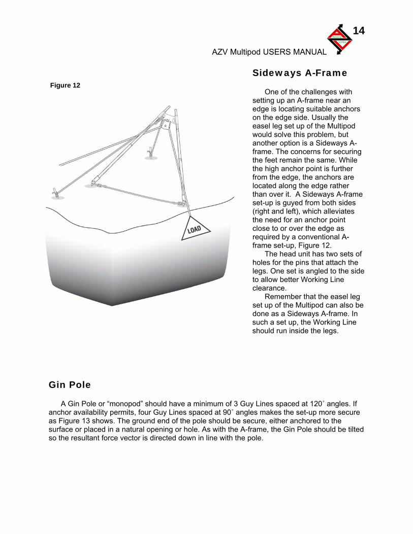
Maximize the force
supported by the legs and minimize the forces on the Guy Lines by leaning the A-frame slightly towards the edge. The legs and the axle of the pulley should line up when the legs bisect the angle of the Working Line through the pulley, as shown in Figure 11. The resultant force should also be centered between the legs. This balances the forces for stability and allows the legs to take most of the load.
Figure 11
AZV Multipod USERS MANUAL
Arizona
Vortex
14
ide
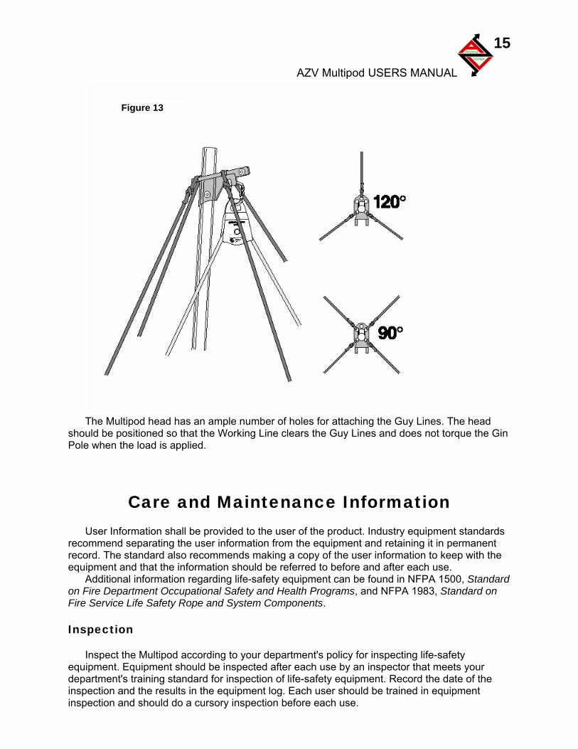
Sideways A-Frame Figure 12
One of the challenges with setting up an A-frame near an edge is locating suitable anchors on the edge side. Usually the easel leg set up of the Multipod would solve this problem, but another option is a Sideways A-frame. The concerns for securing the feet remain the same. While the high anchor point is further from the edge, the anchors are located along the edge rather than over it. A Sideways A-frame set-up is guyed from both sides (right and left), which alleviates the need for an anchor point close to or over the edge as required by a conventional A-frame set-up, Figure 12.
The head unit has two sets of holes for the pins that attach the legs. One set is angled to the sto allow better Working Line clearance.
Remember that the easel leg set up of the Multipod can also be done as a Sideways A-frame. In such a set up, the Working Line should run inside the legs.
Gin Pole
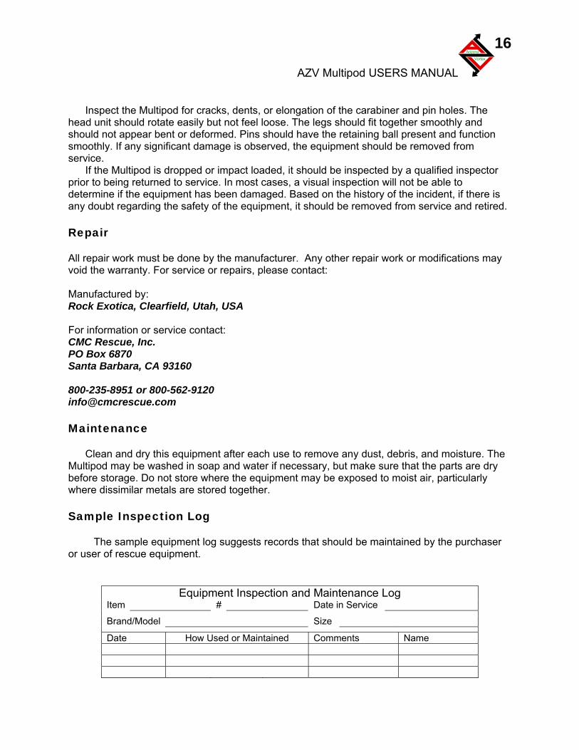
A Gin Pole or “monopod” should have a minimum of 3 Guy Lines spaced at 120˚ angles. If
anchor availability permits, four Guy Lines spaced at 90˚ angles makes the set-up more secure as Figure 13 shows. The ground end of the pole should be secure, either anchored to the surface or placed in a natural opening or hole. As with the A-frame, the Gin Pole should be tilted so the resultant force vector is directed down in line with the pole.
AZV Multipod USERS MANUAL
Arizona
Vortex
15
Figure 13
The Multipod head has an ample number of holes for attaching the Guy Lines. The head should be positioned so that the Working Line clears the Guy Lines and does not torque the Gin Pole when the load is applied.
Care and Maintenance Information
User Information shall be provided to the user of the product. Industry equipment standards recommend separating the user information from the equipment and retaining it in permanent record. The standard also recommends making a copy of the user information to keep with the equipment and that the information should be referred to before and after each use.
Additional information regarding life-safety equipment can be found in NFPA 1500, Standard on Fire Department Occupational Safety and Health Programs, and NFPA 1983, Standard on Fire Service Life Safety Rope and System Components. Inspection
Inspect the Multipod according to your department's policy for inspecting life-safety equipment. Equipment should be inspected after each use by an inspector that meets your department's training standard for inspection of life-safety equipment. Record the date of the inspection and the results in the equipment log. Each user should be trained in equipment inspection and should do a cursory inspection before each use.
AZV Multipod USERS MANUAL
Arizona
Vortex
16
Inspect the Multipod for cracks, dents, or elongation of the carabiner and pin holes. The
head unit should rotate easily but not feel loose. The legs should fit together smoothly and should not appear bent or deformed. Pins should have the retaining ball present and function smoothly. If any significant damage is observed, the equipment should be removed from service.
If the Multipod is dropped or impact loaded, it should be inspected by a qualified inspector prior to being returned to service. In most cases, a visual inspection will not be able to determine if the equipment has been damaged. Based on the history of the incident, if there is any doubt regarding the safety of the equipment, it should be removed from service and retired. Repair
All repair work must be done by the manufacturer. Any other repair work or modifications may void the warranty. For service or repairs, please contact: Manufactured by: Rock Exotica, Clearfield, Utah, USA For information or service contact: CMC Rescue, Inc. PO Box 6870 Santa Barbara, CA 93160 800-235-8951 or 800-562-9120 [email protected] Maintenance
Clean and dry this equipment after each use to remove any dust, debris, and moisture. The Multipod may be washed in soap and water if necessary, but make sure that the parts are dry before storage. Do not store where the equipment may be exposed to moist air, particularly where dissimilar metals are stored together. Sample Inspection Log
The sample equipment log suggests records that should be maintained by the purchaser or user of rescue equipment.
Equipment Inspection and Maintenance Log Item # Date in Service
Brand/Model Size
Date How Used or Maintained Comments Name
AZV Multipod USERS MANUAL
Arizona
Vortex
17
Glossary Artificial High Directional – an elevated change of direction anchor point used to change the direction of the main or Working Line Fall Hazard – location with exposure to a fall Guy Line – a tensioned line that prevents the Multipod from toppling Hazard Zone – location in which a fall hazard exits, usually considered as 6 ft (2 m) from any edge. Resultant Force – the linear direction of the sum of all of the vector forces acting on the component Safety Line or Belay Line – a second rope system design to support the load if the Working Line should fail Tether Line – an 8 or 9 mm Accessory Cord used to prevent sections of the Multipod from falling over the edge if someone slips or lets go Travel Restraint – lanyard, tether, or safety line device that prevents the user from reaching the edge Working Line – the line used to move the load NFPA – National Fire Protection Association © 2005 by CMC Rescue, Inc.