rock krawler suspension systems installation instructions · rock krawler suspension does not...
TRANSCRIPT
INSTALLATION MANUAL
FOR
ROCK KRAWLER SUSPENSION, INC.
JK MID ARM SYSTEMS
12th EDITION

WARNING
Properly block and secure vehicle prior to installation.
Always wear safety glasses when using power tools
Rock Krawler Suspension recommends the use of locktite on all hardware, unless noted otherwise.
The use of limiting straps is recommended to avoid possible damage from over extending the suspension ofyour vehicle.
Do not tighten connections until assemblies are installed in entirety.
Read and understand all instructions, warnings and safety precautions in these instructions and yourowner’s manual before attempting to install these components.
Proper installation of Rock Krawler Suspension products requires knowledge of recommended proceduresfor disassembly/assembly of OE vehicles and components. Access to OE shop manuals and special toolsare required. Attempting to install this kit without knowledge of these procedures may affect the safety ofyour vehicle and or the performance of these components. Rock Krawler Suspension, Inc. stronglyrecommends that this system be installed by a certified mechanic with off road experience.
Rock Krawler Suspension does not recommend combined use of suspension lifts, body lifts or other liftdevices. Combined use of lifts may result in unsafe and unexpected handling characteristics. Also, manystates now have laws restricting Vehicle lift, bumper heights and other alterations. Consult local laws todetermine if your proposed alterations (including installation of this system) comply with your state laws.
Rock Krawler Suspension does not condone or authorize the use of any other suspension components withits products. Should Rock Krawler Systems or components be installed in junction with other products ornot per the provided instructions Rock Krawler Suspension warranty is void and is not to be heldaccountable for any resulting actions.
Note: BE SURE TO CHECK ALL FASTENERS FOR PROPER TORQUE BEFORE TEST DRIVE. RECHECK AFTER 500 MILES AND BE SURE TO CHECK PERIODICALLY.
Driving Tips
For Rock Crawling it is best to have the front sway bar disconnected. This will allow your suspension todo its intended function. Our suspension will give your vehicle unmatched articulation which will give youtraction to keep your vehicle moving. Let the system do the work. This will save on vehicle abuse.
For Mud, especially sloppy mud, it is best to have the front sway bar connected. This will limit thesuspension travel which is better for mud.
For Highway driving it is best to have the front sway bar connected. This will give you the on highwayride and handling characteristics you expect. If you choose otherwise, you do so at your own risk.
IMPORTANCE OF JAM NUTS
This is a note about jam nuts and the consumer's responsibility. The installer is the person or persons initially responsible for the proper setup of the suspension system and/or components and the initial tightening of the jam nuts. The jam nuts not only hold the orientation of the joint it is on but it is the single component that puts the necessary pre-load on the joints threads. The consumer or vehicle owner is the person or persons responsible for maintaining the jam nuts tightness. Failure to do so will result in the rapid deterioration of the threads in the control arm and will impose a "cause for concern" for the occupants of the vehicle. Failure to comply with the warnings headed in the directions regarding the amount of threads showing past the jam nut will also result in the same "cause for concern" for the occupants of the vehicle. All of the above items are the responsibility of the vehicle owner and or installer. If a threaded section of a component is bad it will show itself defective immediately. Threads that fail over time are due to improper maintenance of jam nuts and can be proven very easily. Thread sections and jam nuts not properly maintained or setup, are not covered under warranty. This is the end user and installer's responsibility.
ORIENTATION OF JOINTS
Orient the Krawler Joint for maximum amount of movement with the head of joint perpendicular to bolt / head of the joint vertical in the bracket it is mounting in. This same rule for orientation needs to be followed for all heim joints also. The photo below shows the right way (LEFT SIDE) and the wrong way (RIGHT SIDE) to orient a joint

^RIGHT WAY^ ^WRONG WAY^
MAINTAINING JOINTS
KRAWLER JOINTS (Rebuildable spherical joints):
The Pro Series Krawler Joints are greaseable. The grease valley is machined into the housing. The joints are very tight and typically a pneumatic grease gun is required. Approximately every 6 months or so the joints should be greased. They will not take a lot of grease! Use a general purpose light Marine Grade grease or similar product.
If the joint is not loose, it is not bad. Only if the joint is loose is it a bad joint and should be rebuilt. Krawler Joint Raceways are available for all series of Krawler Joints through Rock Krawler or an authorized dealer.
Please note: If you are not using the articulation of the Krawler Joint, the lubrication will not be moving around. In such cases we recommend spraying down the outside of the Joint with WD-40 or similar lubricant to ensure the race ways do not dry out, become brittle and crack..
HEIM JOINTS (Non- rebuildable spherical joints)
All Rock Krawler Heim Joints use a Teflon Liner and thus are self lubricating. They too can also benefit from spraying down the outside of them liberally with WD-40 or similar lubricant. Grease should not be applied.
FLEX JOINTS (Rebuildable bushing joints)
Our Flex Joints (bushing end) will benefit from being greased routinely. If there is no grease fitting, spray the exterior of the joint with WD-40 or similar lubricant.
*****Component Starting Lengths If you have a 1.5” System*****
ALL 1.5” KITS
1.5” Front Track Bar Assembled Length = 32 1/2”1.5” Rear Track Bar Assembled Length = 39 11/16”
1.5” Front Upper Control Arm = 19 1/4”1.5” Front Lower Control Arm Assembled Length = 23 1/16”
EXPEDITION / MAX TRAVEL 1.5” KITS
1.5” Expedition/Max Travel Rear Lower Control Arm = Match OEM Length
X-FACTOR 1.5” KITS
1.5” X-Factor Rear Upper Control Arm (2 door) = 18 9/16”1.5” X-Factor Rear Upper Control Arm (4 door) = 18”
1.5” X-Factor Rear Lower Control Arm (2 door) = 20 1/2”1.5” X-Factor Rear Lower Control Arm (4 door) = 20 5/8”
*****Component Starting Lengths If you have a 2.5” System*****
ALL 2.5” KITS
2.5” Front Track Bar Assembled Length = 32 9/16”2.5” Rear Track Bar Assembled Length = 39 3/4”
2.5” Front Upper Control Arm Assembled Length = 19 5/16” 2.5” Front Lower Control Arm Assembled Length = 23 1/8”
MAX TRAVEL 2.5” KITS
2.5” Max Travel Rear Lower Control Arm (2 Door) = 19 5/8” 2.5” Max Travel Rear Lower Control Arm (4 Door) = 20 1/8”
X-FACTOR 2.5” KITS
2.5” X-Factor Rear Upper Control Arm (2 Door) = 18 5/8”

2.5” X-Factor Rear Upper Control Arm (4 Door) = 18 1/16” 2.5” X-Factor Rear Lower Control Arm (2 Door) = 20 9/16” 2.5” X-Factor Rear Lower Control Arm (4 Door) = 20 11/16”
*****Component Starting Lengths If you have a 3.5” System*****
ALL 3.5” KITS
3.5” Front Track Bar Assembled Length = 32 5/8”3.5” Rear Track Bar Assembled Length = 39 3/4”
3.5” Front Upper Control Arm Assembled Length = 19 3/8”3.5” Front Lower Control Arm Assembled Length = 23 1/8”
FLEX SYSTEM 3.5” KITS
3.5” Flex System Rear Lower Control Arm (2 Door) = 19 1/2” 3.5” Flex System Rear Lower Control Arm (4 Door) = 20”
X-FACTOR 3.5” KITS
3.5” X-Factor Rear Upper Control Arm (2 Door) = 19 1/8”3.5” X-Factor Rear Upper Control Arm (4 Door) = 18 9/16”
3.5” X-Factor System Rear Lower Control Arm (2 Door) = 20 5/8” 3.5” X-Factor System Rear Lower Control Arm (4 Door) = 21”
Note: All Control Arms and Track Bars come pre-assembled, but they require final adjustment as specified in the directions above. These measurements are taken from the center of one bolt hole to center of the other bolt hole.

TORQUE VALUES FOR HARDWARE AND JAM NUTS
All 14mm and 9/16” bolts are torqued to 90-100 ft-lbs. All 12mm and ½” bolts are torqued to 75-80 ft-lbs. All 10mm and 3/8 bolts are torqued to 30-35 ft-lbs. All 7/8” Jam Nuts are to be torqued 200-220 ft-lbs. Up to ½” of threads showing past the jam nut is safe for
final adjustment. These specifications are critical for the overall longevity of the threaded section. All 1” Jam Nuts are to be torqued to 250-300 ft-lbs. GET YOUR BIG BOY PANTS ON! Up to 5/8” of
threads showing past the jam nut is safe for final adjustment. These specifications are critical for the overalllongevity of the threaded section.
FRONT OF VEHICLE
Make sure vehicle is on a level, hard working surface if you are using a floor jack and jack stands.
Block the rear wheels so the vehicle cannot move and make sure the emergency brake is applied.
Raise the front of vehicle and support with safety jack stands. Locate jack stands on the frame in front ofthe axle.
If you are using a vehicle lift, place the lift arms according to those specific vehicles lifting procedures.Ensure that the lift arms will not interfere with the components that are being replaced.
Remove the front rims and tires with axle supported by a floor jack.
Remove the front shocks. Save the OEM hardware to install the new shocks.
Remove the front sway bar links.
Lower the front axle assembly onto jack stands.
Remove the front track bar from the vehicle and save the OEM hardware for reuse.
Remove the front springs.

(FLEX / EXPEDITION / X-FACTOR / MAX TRAVEL) Remove the front lower control arms and savethe OEM hardware for reuse.
(X-FACTOR KITS) Remove the front upper control arms and save the OEM hardware for reuse.
Note: You may need to cut the passenger side front upper control arm bolt at the frame depending on the year of your JK. We have provided you with a new 12mm x 90mm bolt, washers, and nyloc nut.
(X-FACTOR KITS) Install the supplied front upper control arms set to the specified length for your kitaccording to our measurements. Secure using the OEM hardware OR a combination of OEM and oursupplied 12mm x 90mm bolt, washers. and 12mm nyloc nut depending on the year of your vehicle.
Note: If you are installing this kit with an aftermarket axle housing you may have to clearance the clevis mount on the upper control arm slightly.
(FLEX / EXPEDITION / X-FACTOR / MAX TRAVEL) Install the front lower control arms set to thespecified length for your kit according to our measurements using OEM hardware.
Note: The bend in the arms is for improved ground clearance, the Monster Krawler Joint (spherical joint) is placed at the axle and the Monster Bushing Joint at the frame.
(ALL X-FACTOR KITS) Install the supplied front spring retainer clips and secure the spring clip with thesupplied 10mm x 35 mm bolts and nylok nuts.
Note: Place clip on the bottom coil, mark the hole in the spring pad and then drill a 10mm hole. The Driver’s Side is shown below and the clip sits behind the axle as shown. On the Passenger Side it is the opposite.

Install bump stops at this time if you have purchased them.
Note: To install mark the center of the spring pad and drill a 7/16” hole. Tap the hole you drilled to ½”x13 for the suppied hardware. Place the bump stop inside the coil spring and place the coil and bump stop onto the spring mount together. Tighten the hardware once the coil is placed on the spring pad.
Install the supplied front coil springs. Make sure the end of the coil spring sits in the spring mount just as itdid from the factory. If the coil is not seated properly it will bow more then it should and can damage yourcoil.
Install the front shocks using OEM hardware.
REAR OF VEHICLE
Make sure vehicle is on a level, hard working surface if you are using a floor jack and jack stands.
Block the front wheels so the vehicle cannot move.
Raise the rear of vehicle and support with safety jack stands. Locate jack stands on the frame behind therear axle.
If you are using a vehicle lift, place the lift arms according to those specific vehicles lifting procedures.Ensure that the lift arms will not interfere with the components that are being replaced.
Remove the rear rims and tires with axle supported by a floor jack.
Remove the rear shocks. Save the OEM hardware for reuse.
Remove the rear sway bar links and save for reuse if your kit requires it.
Lower the rear axle assembly onto jack stands.
Remove the rear coil springs.
Remove the rear track bar, save it and the OEM hardware for reuse.
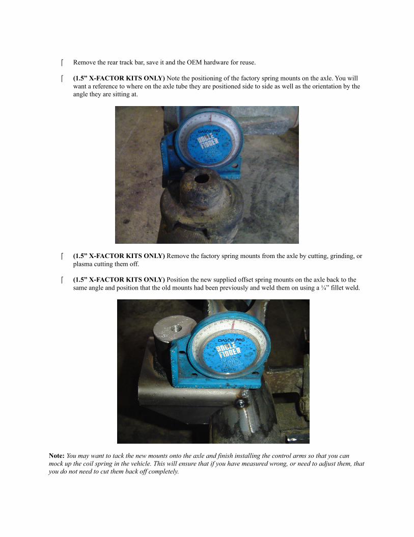
(1.5” X-FACTOR KITS ONLY) Note the positioning of the factory spring mounts on the axle. You willwant a reference to where on the axle tube they are positioned side to side as well as the orientation by theangle they are sitting at.
(1.5” X-FACTOR KITS ONLY) Remove the factory spring mounts from the axle by cutting, grinding, orplasma cutting them off.
(1.5” X-FACTOR KITS ONLY) Position the new supplied offset spring mounts on the axle back to thesame angle and position that the old mounts had been previously and weld them on using a ¼” fillet weld.
Note: You may want to tack the new mounts onto the axle and finish installing the control arms so that you can mock up the coil spring in the vehicle. This will ensure that if you have measured wrong, or need to adjust them, that you do not need to cut them back off completely.

(FLEX / EXPEDITION / X-FACTOR / MAX TRAVEL) Remove the rear lower control arms and savethe OEM hardware for reuse.
(ALL X-FACTOR KITS) Remove the factory rear upper control arms and discard them, save the OEMhardware for reuse.
Install the rear track bar relocation bracket using the OEM bolt and the supplied 7/8” O.D. x 9/16 I.D. x1.625” long crush sleeve on the inside of the OEM lower track bar mount as shown below. Drill a 10mmhole through the top of the OEM bracket where the existing hole is in out new bracket and secure it withthe supplied 10mm x 35mm bolt and 10mm nyloc nut.
Note: Tighten the 10mm hardware on the top of the bracket first to ensure the bracket sits flush and then tighten the remainder of the hardware. The OEM factory rear track bracket is weak so we require that the legs of our bracket be welded to the axle tube. This will prevent any failures of the rear track bracket assembly during hard use of your vehicle.
(ALL X-FACTOR KITS) Install the rear upper control arms set to the specified length for your kitaccording to our measurements and secure using the OEM hardware.
Note: When setting length, balance the amount of thread showing past the jam nuts. Setup the arm so the bend in the arm lays horizontal and towards the frame for increased tire clearance.
( EXPEDITION / 3.5” FLEX / X-FACTOR / MAX TRAVEL) Install the rear lower control arms set tothe specified length for your kit according to our measurements using OEM hardware.
Note: The bend in the arms is for improved ground clearance, the Monster Krawler Joint (spherical joint) is placed at the axle and the Monster Bushing Joint at the frame.
(STOCK MOD / EXPEDITION / FLEX / 2.5” MAX TRAVEL) Reinstall the factory rear track bar inthe newly supplied rear track bar bracket with the supplied 14mm x 80mm bolt, washers and nyloc nuts.
(X-FACTOR) Install the supplied rear track bar set to the specified length for your kit according to ourmeasurements. Secure the frame connection with the OEM hardware and the axle connection with thesupplied 14mm x 80mm bolt, 14mm washers, and 14mm nyloc nuts.
Note: When setting length, balance the amount of thread showing past the jam nuts. The bushing end goes at the frame and the heim joint end goes to the factory bracket at the axle. The bend in the track bar is for clearance of the differential and the orientation of the track bar is controlled by locking the jam nut of the flex joint at the frame. Once the vehicle is on the ground, you will need to check that the axle is centered under the vehicle. If not centered, adjust the track bar so the axle is centered.
IMPORTANT REAR TRACK BAR INFORMATION
If your coil spring and track bar make contact, you can break the jam nuts free on the track bar while it is bolted in place. Then roll the bend of the bar back away from the coil spring and loctite and tighten your jam nuts again. If you still have issues after doing this, you may need to adjust your pinion angle and/or wheelbase by adjusting the control arms.
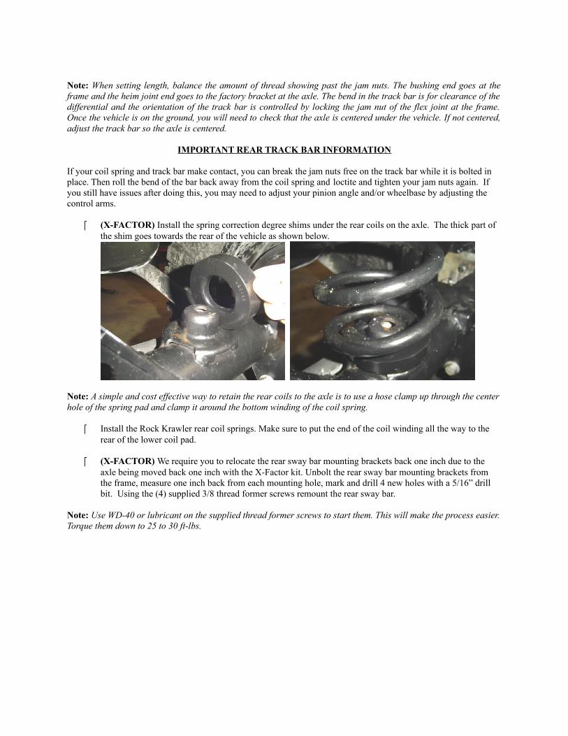
(X-FACTOR) Install the spring correction degree shims under the rear coils on the axle. The thick part ofthe shim goes towards the rear of the vehicle as shown below.
Note: A simple and cost effective way to retain the rear coils to the axle is to use a hose clamp up through the center hole of the spring pad and clamp it around the bottom winding of the coil spring.
Install the Rock Krawler rear coil springs. Make sure to put the end of the coil winding all the way to therear of the lower coil pad.
(X-FACTOR) We require you to relocate the rear sway bar mounting brackets back one inch due to theaxle being moved back one inch with the X-Factor kit. Unbolt the rear sway bar mounting brackets fromthe frame, measure one inch back from each mounting hole, mark and drill 4 new holes with a 5/16” drillbit. Using the (4) supplied 3/8 thread former screws remount the rear sway bar.
Note: Use WD-40 or lubricant on the supplied thread former screws to start them. This will make the process easier. Torque them down to 25 to 30 ft-lbs.

Remove the wire hanger for the rear emergency brake cable and route them to have as much slack aspossible.
Install the rear shocks using the OEM hardware.
Note: We recommend the rear shock bodies should be no more than 2” in diameter or there is a risk of the rear shock contacting the rear track bar relocation bracket.
Install bump stops if purchased additionally.
Note: Our rear fabricated bump stops mount to the factory bump stop pad on the rear axle using the supplied hardware. Use the existing holes in the factory pads. Make sure the bumps stop angles to the front of the vehicle as shown in the photo below.
Install rims and tires and lower the vehicle to the ground.
*BRAKE LINES*
Front: (EXPEDITION / FLEX / X-FACTOR/ MAX TRAVEL) Remove the factory front rubber brakelines and install the supplied extended stainless steel brake lines. Be sure to add slack to your ABS linesand route them with your new stainless steel lines using the supplied zip ties to secure them to each other.
Do not worry about bleeding the brake system at this time unless your kit does not come with rear brake lines.
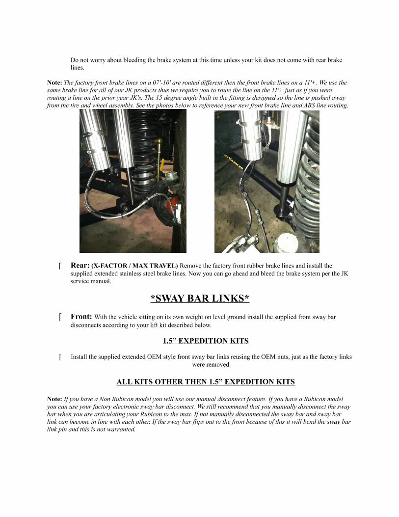
Note: The factory front brake lines on a 07'-10' are routed different then the front brake lines on a 11'+. We use the same brake line for all of our JK products thus we require you to route the line on the 11'+ just as if you were routing a line on the prior year JK's. The 15 degree angle built in the fitting is designed so the line is pushed away from the tire and wheel assembly. See the photos below to reference your new front brake line and ABS line routing.
Rear: (X-FACTOR / MAX TRAVEL) Remove the factory front rubber brake lines and install thesupplied extended stainless steel brake lines. Now you can go ahead and bleed the brake system per the JKservice manual.
*SWAY BAR LINKS*
Front: With the vehicle sitting on its own weight on level ground install the supplied front sway bardisconnects according to your lift kit described below.
1.5” EXPEDITION KITS
Install the supplied extended OEM style front sway bar links reusing the OEM nuts, just as the factory linkswere removed.
ALL KITS OTHER THEN 1.5” EXPEDITION KITS
Note: If you have a Non Rubicon model you will use our manual disconnect feature. If you have a Rubicon model you can use your factory electronic sway bar disconnect. We still recommend that you manually disconnect the sway bar when you are articulating your Rubicon to the max. If not manually disconnected the sway bar and sway bar link can become in line with each other. If the sway bar flips out to the front because of this it will bend the sway bar link pin and this is not warranted.

TOPUse the supplied ½” x 2.5” bolt, .595” long spacer, and nyloc nut. Note the shoulder of the spacer goes against the sway bar itself.
Top Sway Bar Connection
BOTTOMFor the bottom connection attach the ½” x 2.0” long bolt with cross drilled hole to the factory sway bar link bracket. Secure the bolt with the supplied ½” jam nut. If you have a non-rubicon you can attach the bottom end of the sway bar link with the 2 nylon washers on either side of the rod end and secure it with the hair pin OR you can use the wingnut and lock washer for a little quieter operation. If you have a rubicon you can simply secure the bottom rod end with the supplied ½” nylok nut.
Bottom: Non-Rubicon Wingnut Bottom: Non-Rubicon Hairpin Bottom: Rubicon
Note: On some front sway bars you may have to ream out the hole out with a ½” drill bit. Start with the heims threaded entirely onto the pin, then fine tune the length of one of them to ease in removal and installation of the disconnect when parked on flat and level ground. Tighten the jam nuts against the heims after the heims have been oriented for maximum articulation. Ideally you want the heims parallel to each other and point straight forward.
Rear: With the vehicle sitting on its own weight on level ground install the supplied rear sway bardisconnects.
(STOCK MOD / EXPEDITION / 2.5” FLEX) Reinstall the factory rear sway bar links using the OEM hardware.
(2.5” MAX TRAVEL / 3.5” FLEX) Install the supplied rear sway bar links on the outside of the OEM brackets and Sway Bar. Make sure the large washer is against the exposed bushing of the sway bar link and the smaller

washer on the other side of the sway bar itself or the axle mount.
(X-FACTOR) Install the supplied rear sway bar links using the supplied hardware as shown below. Note the shoulder of the spacer goes towards the sway bar and the bottom mounting bracket.
Note: Start with the heims threaded entirely onto the pin, then fine tune the length of one of them to ease in removal and installation of the disconnect when parked on flat and level ground. Tighten the jam nuts against the heims after the heims have been oriented for maximum articulation. Ideally you want the heims parallel to each other and point straight forward.

To install your sway bar link straps:
Drill a 5/16” hole in the sheet metal where show in the picture below.
Apply a finish of your choice and let it dry. Install the sway bar link strap using the supplied 5/16” x 1” bolt, washers and nyloc nut.
When disconnecting the sway bar links hold them up as show in the picture below.
Note: Swing them up to the side of the sway bar itself. Use the loose part of the strap to wrap around the sway bar and sway bar link by feeding the fabric end through the metal loop end. Once wrapped around the sway bar and sway bar link, feed the fabric end through the buckle attached to the vehicle and synch it up tight.
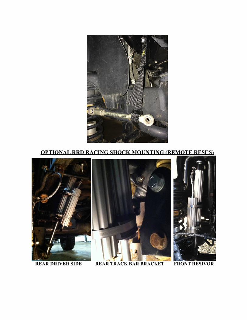
OPTIONAL RRD RACING SHOCK MOUNTING (REMOTE RESI’S)
REAR DRIVER SIDE REAR TRACK BAR BRACKET FRONT RESIVOR

Before hitting the pavement or the trails be sure to make sure the control arms are oriented properly, all spherical joints (heim joints and Krawler Joints) are oriented correctly to allow for maximum movement without bind, and all jam nuts have locktite on them and are tight. Make sure the axles are properly centered, pinion angles are correct, there is proper slack in ABS lines, and all lines are properly routed. Go back over all your hardware and make sure each connection is tightened to its proper torque spec. Check your vehicles articulation and ensure that no moving parts contact or interfere with any other components throughout the travel (brake lines, shocks, coils, swaybar links). Also check to see if at full flex your coil spring losses tension, if so you may want to look into a limit straps. You may need to look at bump stops depending on what shocks you choose to run.
Congratulations, you have just finished installing your Rock Krawler Suspension System! Your Jeep is now free to roam
about the country.