rock linings, rr-1 - international erosion control association
TRANSCRIPT
© Catchments & Creeks Pty Ltd Version 2 - May 2010 Page 1
Rock Linings DRAINAGE CONTROL TECHNIQUE
Low Gradient ✔ Velocity Control Short Term ✔
Steep Gradient ✔ Channel Lining ✔ Medium-Long Term ✔
Outlet Control Soil Treatment Permanent [1][1] The design of permanent installations may require consideration of issues not covered in this fact
sheet, such as the effects of sedimentation and vegetation growth across the rock-lined surface.
Symbol
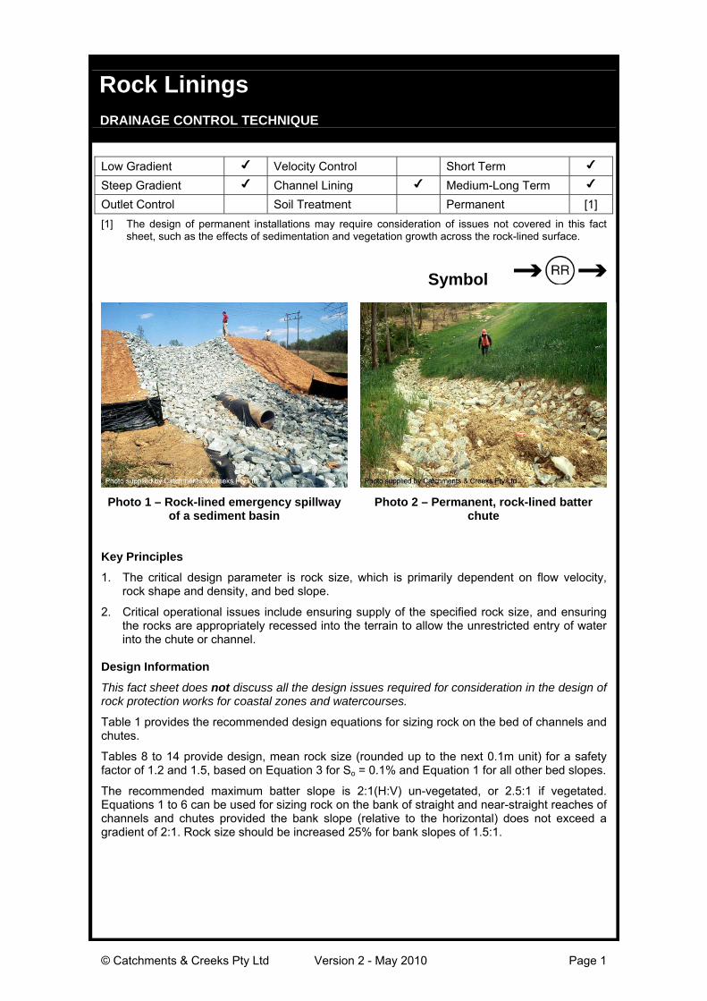
Photo 1 – Rock-lined emergency spillwayof a sediment basin
Photo 2 – Permanent, rock-lined batterchute
Key Principles
1. The critical design parameter is rock size, which is primarily dependent on flow velocity,rock shape and density, and bed slope.
2. Critical operational issues include ensuring supply of the specified rock size, and ensuringthe rocks are appropriately recessed into the terrain to allow the unrestricted entry of waterinto the chute or channel.
Design Information
This fact sheet does not discuss all the design issues required for consideration in the design ofrock protection works for coastal zones and watercourses.
Table 1 provides the recommended design equations for sizing rock on the bed of channels andchutes.
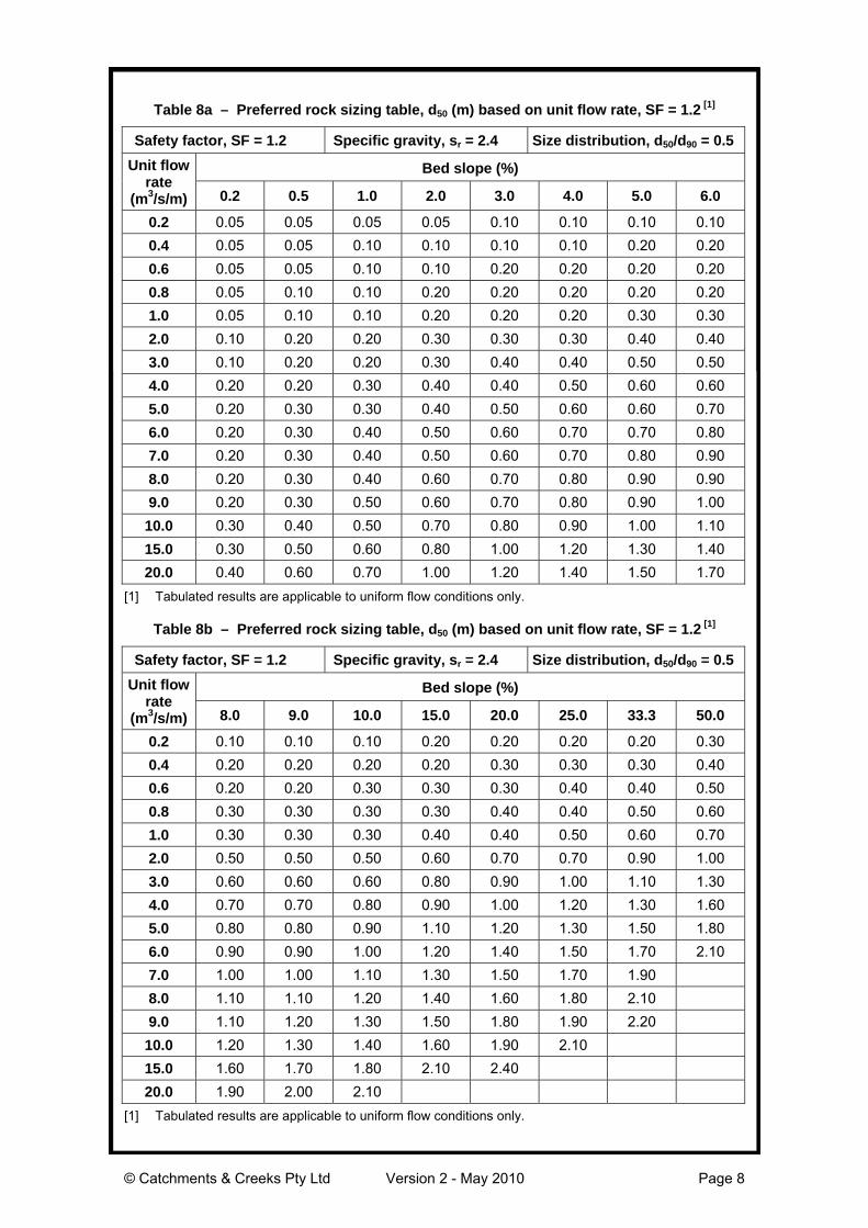
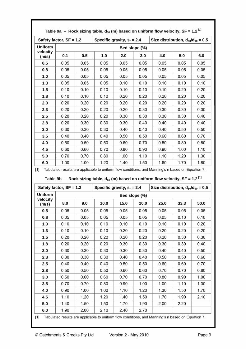
Tables 8 to 14 provide design, mean rock size (rounded up to the next 0.1m unit) for a safetyfactor of 1.2 and 1.5, based on Equation 3 for So = 0.1% and Equation 1 for all other bed slopes.
The recommended maximum batter slope is 2:1(H:V) un-vegetated, or 2.5:1 if vegetated.Equations 1 to 6 can be used for sizing rock on the bank of straight and near-straight reaches ofchannels and chutes provided the bank slope (relative to the horizontal) does not exceed agradient of 2:1. Rock size should be increased 25% for bank slopes of 1.5:1.
© Catchments & Creeks Pty Ltd Version 2 - May 2010 Page 2
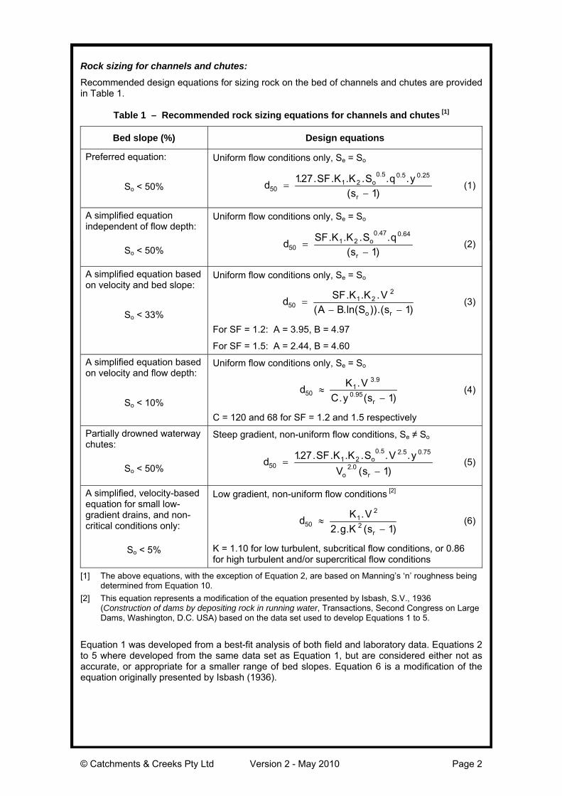
Rock sizing for channels and chutes:
Recommended design equations for sizing rock on the bed of channels and chutes are providedin Table 1.
Table 1 – Recommended rock sizing equations for channels and chutes [1]
Bed slope (%) Design equations
Preferred equation:
So < 50%
Uniform flow conditions only, Se = So
d SF K K S q ys
o
r50
1 20 5 0 5 0 25127
1=
−. . . . . . .
( )
. . .
(1)
A simplified equationindependent of flow depth:
So < 50%
Uniform flow conditions only, Se = So
d SF K K S qs
o
r50
1 20 47 0 64
1=
−. . . .
( )
. .
(2)
A simplified equation basedon velocity and bed slope:
So < 33%
Uniform flow conditions only, Se = So
d SF K K VA B S so r
501 2
2
1=
− −. . .
( .ln( )).( )(3)
For SF = 1.2: A = 3.95, B = 4.97
For SF = 1.5: A = 2.44, B = 4.60
A simplified equation basedon velocity and flow depth:
So < 10%
Uniform flow conditions only, Se = So
d K VC y sr
501
3 9
0 95 1≈
−.
. ( )
.
. (4)
C = 120 and 68 for SF = 1.2 and 1.5 respectively
Partially drowned waterwaychutes:
So < 50%
Steep gradient, non-uniform flow conditions, Se ≠ So
d SF K K S V yV s
o
o r50
1 20 5 2 5 0 75
2 0127
1=
−. . . . . . .
( )
. . .
. (5)
A simplified, velocity-basedequation for small low-gradient drains, and non-critical conditions only:
So < 5%
Low gradient, non-uniform flow conditions [2]
d K Vg K sr
501
2
22 1≈
−.
. . ( )(6)
K = 1.10 for low turbulent, subcritical flow conditions, or 0.86for high turbulent and/or supercritical flow conditions
[1] The above equations, with the exception of Equation 2, are based on Manning’s ‘n’ roughness beingdetermined from Equation 10.
[2] This equation represents a modification of the equation presented by Isbash, S.V., 1936(Construction of dams by depositing rock in running water, Transactions, Second Congress on LargeDams, Washington, D.C. USA) based on the data set used to develop Equations 1 to 5.
Equation 1 was developed from a best-fit analysis of both field and laboratory data. Equations 2to 5 where developed from the same data set as Equation 1, but are considered either not asaccurate, or appropriate for a smaller range of bed slopes. Equation 6 is a modification of theequation originally presented by Isbash (1936).

© Catchments & Creeks Pty Ltd Version 2 - May 2010 Page 3
Terminology used in Equations 1 to 6:d50 = nominal rock size (diameter) of which 50% of the rocks are smaller [m]
A & B = equation constantsK = equation constant based on flow conditions
= 1.10 for low turbulent, subcritical flow conditions, or 0.86 for high turbulent and/orsupercritical flow conditions
K1 = correction factor for rock shape= 1.0 for angular (fractured) rock, 1.36 for rounded rock (i.e. smooth, spherical rock)
K2 = correction factor for rock grading= 0.95 for poorly graded rock (Cu = d60/d10 < 1.5), 1.05 for well graded rock (Cu > 2.5),
otherwise K2 = 1.0 (1.5 < Cu < 2.5)q = flow per unit width down the embankment [m3/s/m]sr = specific gravity of rock
Se = slope of energy line [m/m]So = bed slope = tan(θ) [m/m]SF = factor of safety (refer to Table 2)
V = actual depth-average flow velocity at location of rock [m/s]Vo = depth-average flow velocity based on uniform flow down a slope, So [m/s]y = depth of flow at a given location [m]θ = slope of channel bed [degrees]Φ = angle of repose of rock [degrees]
Table 2 – Recommended safety factor for use in determining rock size
Safetyfactor (SF) Recommended usage Example site conditions
1.2 • Low risk structures.
• Failure of structure is mostunlikely to cause loss of life orirreversible property damage.
• Permanent rock chutes with allvoids filled with soil and pocketplanted.
• Embankment chutes where failureof the structure is likely to result ineasily repairable soil erosion.
• Permanent chutes that are likelyto experience significantsedimentation and vegetationgrowth before experiencing thehigh flows.
• Temporary (<2yrs) spillways witha design storm of 1 in 10 years ofgreater.
1.5 • High risk structures.
• Failure of structure may causeloss of life or irreversible propertydamage.
• Temporary structures that have ahigh risk of experiencing thedesign discharge while the voidsremain open (i.e. prior tosediment settling within andstabilising the voids betweenindividual rocks).
• Waterway chutes where failure ofthe chute may cause severe gullyerosion and/or damage to thewaterway.
• Sediment basin or dam spillwayslocated immediately up-slope of aresidential area or busy roadwaywhere an embankment failurecould cause property flooding orloss of life.
• Spillways and chutes designed fora storm frequency less than 1 in10 years.

© Catchments & Creeks Pty Ltd Version 2 - May 2010 Page 4
Design flow velocity:
Wherever practical, the flow velocity used to determine rock size should be based on the ‘local’velocity (i.e. the depth-average flow velocity at a given location) rather than a flow velocityaverage over the whole cross-section.
Rock placed on the outside bank of drainage and waterway channels can be sized usingEquations 4 or 6 (as appropriate) provided the bank slope does not exceed 2:1. In suchcircumstances the terms as used in Equations 4 and 6 are defined below:
V = flow velocity adjacent bank (Vbend)y = depth of flow measured to the toe of the bank
So = slope of main channel bed (not the slope of the bank)
In large channels, the local flow velocity on the outside of any significant channel bend shouldbe adopted as 1.33 times the average channel velocity, unless otherwise supported by physicalmodelling.
Rock type, size and grading:
The rock should be durable and resistant to weathering, and should be proportioned so thatneither the breadth nor the thickness of a single rock is less than one-third its length. Generally,crushed (angular) rock is more stable than rounded stone.
Suggested relative densities of various types of rock are provided in Table 3.
Table 3 – Typical relative density (specific gravity) of rock
Rock type Relative density (sr)Sandstone 2.1 to 2.4
Granite 2.5 to 3.1, commonly 2.6Limestone 2.6
Basalt 2.7 to 3.2
The maximum rock size should generally not exceed twice the nominal (d50) rock size.
Table 4 provides a typical rock size distribution for use in preliminary design. Table 4 is providedfor general information only, it does not represent a recommended design specification.
Table 4 – Typical distribution of rock size [1]
Rock size ratio Assumed distribution valued100/d50 2.00d90/d50 1.82d75/d50 1.50d65/d50 1.28d40/d50 0.75d33/d50 0.60d10/d50 > 0.50
[1] Wide variations in the rock size distribution can occur unless suitably controlled by the materialcontract specifications.
Thickness of rock protection:
The thickness of the rock protection should be sufficient to allow at least two overlapping layersof the nominal (d50) rock size.
The thickness of rock protection must also be sufficient to accommodate the largest rock size.
In order to allow at least two layers of rock, the minimum thickness of rock protection (T) can beapproximated by the values presented in Table 5.

© Catchments & Creeks Pty Ltd Version 2 - May 2010 Page 5
Table 5 – Minimum thickness (T) of rock lining
Min. Thickness (T) Size distribution (d50/d90) Description1.4 d50 1.0 Highly uniform rock size1.6 d50 0.8 Typical upper limit of quarry rock1.8 d50 0.67 Recommended lower limit of distribution2.1 d50 0.5 Typical lower limit of quarry rock
Backing material or filter layer:
Non-vegetated armour rock must be placed over a layer of suitably graded filter rock orgeotextile filter cloth (minimum ‘bidim’ A24 or equivalent). The geotextile filter cloth must havesufficient strength and must be suitably overlapped to withstand the placement of the rock.
Armour rock that is intended to be vegetated by appropriately filling all voids with soil and pocketplanting generally will usually not require an underlying filter layer, unless the long-term viabilityof the vegetation is questioned due to possible high scour velocities, or limited natural light orrainfall conditions.
If the soils adjacent to the rock surface are dispersive (e.g. sodic soils), then prior to placing thefilter cloth or filter layer, the exposed bank must first be covered with a layer of non-dispersivesoil (Figure 2), typically minimum 200mm thickness, but preferably 300mm.
Figure 1 – Rock placement (withoutvegetation) on non-dispersive soil
Figure 2 – Rock placement (withoutvegetation) on dispersive soil
Maximum bank gradient:
The recommended maximum batter slope is 2:1(H:V) un-vegetated, or 2.5:1 if vegetated.
Typical angles of repose for dumped rock are provided in Table 6.
Table 6 – Typical angle of repose for rock
Angle of repose (degrees)Rock shape
Rock size >100mm Rock size >500mmVery angular rock 41o 42o
Slightly angular rock 40o 41o
Moderately rounded rock 39o 40o
Placement of vegetation over the rock cover:
Vegetating rock-lined channels and chutes can significantly increase the stability of thesedrainage structures, but can also reduce the hydraulic capacity of the structure.
Relying on wild revegetation of rock-protected surfaces can encourage the invasion of weedspecies, and is therefore not recommended.

© Catchments & Creeks Pty Ltd Version 2 - May 2010 Page 6
Manning roughness of rock-lined surfaces:
The Manning’s (n) roughness for rock-lined surfaces may be determined from Table 7 orEquation 7.
Table 7 – Manning’s (n) roughness of rock-lined surfaces
d50/d90 = 0.5 d50/d90 = 0.8d50 = 200mm 300mm 400mm 500mm 200mm 300mm 400mm 500mmR (m) Manning’s roughness (n) Manning’s roughness (n)
0.2 0.10 0.14 0.17 0.21 0.06 0.08 0.09 0.110.3 0.08 0.11 0.14 0.16 0.05 0.06 0.08 0.090.4 0.07 0.09 0.12 0.14 0.04 0.05 0.07 0.080.5 0.06 0.08 0.10 0.12 0.04 0.05 0.06 0.070.6 0.06 0.08 0.09 0.11 0.04 0.05 0.05 0.060.8 0.05 0.07 0.08 0.09 0.04 0.04 0.05 0.061.0 0.04 0.06 0.07 0.08 0.03 0.04 0.05 0.05
The roughness values presented in Table 7 have been developed from Equation 7. Equation 7(Witheridge, 2002) was developed to allow estimation of the Manning's n of rock lined channelsin shallow water.
n dX
=−
901 6
26 1 0 35930 7
/
( )( . ). (Eqn 7)
where: X = (R/d90)(d50/d90)R = Hydraulic radius of flow over rocks [m]
d50 = mean rock size for which 50% of rocks are smaller [m]d90 = mean rock size for which 90% of rocks are smaller [m]
For ‘natural’ rock extracted from streambeds the relative roughness value (d50/d90) is typically inthe range 0.2 to 0.5. For quarried rock the ratio is more likely to be in the range 0.5 to 0.8.
Placement of rock:
It is important to ensure that the top of the rock surface is level with, or slightly below, thesurrounding land surface to allow the free entry of water including lateral inflows (if required) asshown in Figure 4.
Figure 3 – Incorrect placement of rockcausing loss of flow area and erosion
along the outer limits of the rock
Figure 4 – Rock recessed into the soil toallow the free entry of lateral inflows

© Catchments & Creeks Pty Ltd Version 2 - May 2010 Page 7
Most failures of rock-lined hydraulic structures are believed to occur as a result of inappropriateplacement of the rock, either due to inadequate design detailing, or poorly supervisedconstruction practices. Rock-lined channels and chutes are usually most vulnerable to damagein the first year or two after placement while the voids remain open and free of sedimentation.
Where appropriate, permanent rock-lined channels and chutes should be topped with a lightcovering of soil and planted to accelerate the integration of these structures into the surroundingenvironment. Revegetation is not however always advisable, and should be assessed on acase-by-case basis.
Photo 3 – An example of the rock-liningbeing correctly recessed into the
topography
Photo 4 – Note how runoff from theadjacent batter is able to spill freely into
the drain
Photo 5 – Placement of the rock on thesoil can result in erosion problems if
significant lateral inflows occur
Photo 6 – In this example, placement ofthe rock has resulted in the rock-lined tabledrain being higher than the road shoulder
Photo 7 – Rounded rock can besignificantly less stable than angular,
fractured rock, especially when placed onsteep slopes
Photo 8 – Placement of a few large,anchor rocks down a steep slope will nothelp stabilise adjacent, under-sized rocks,
and will likely cause flow diversion
© Catchments & Creeks Pty Ltd Version 2 - May 2010 Page 8
Table 8a – Preferred rock sizing table, d50 (m) based on unit flow rate, SF = 1.2 [1]
Safety factor, SF = 1.2 Specific gravity, sr = 2.4 Size distribution, d50/d90 = 0.5
Bed slope (%)Unit flowrate
(m3/s/m) 0.2 0.5 1.0 2.0 3.0 4.0 5.0 6.0
0.2 0.05 0.05 0.05 0.05 0.10 0.10 0.10 0.100.4 0.05 0.05 0.10 0.10 0.10 0.10 0.20 0.200.6 0.05 0.05 0.10 0.10 0.20 0.20 0.20 0.200.8 0.05 0.10 0.10 0.20 0.20 0.20 0.20 0.201.0 0.05 0.10 0.10 0.20 0.20 0.20 0.30 0.302.0 0.10 0.20 0.20 0.30 0.30 0.30 0.40 0.403.0 0.10 0.20 0.20 0.30 0.40 0.40 0.50 0.504.0 0.20 0.20 0.30 0.40 0.40 0.50 0.60 0.605.0 0.20 0.30 0.30 0.40 0.50 0.60 0.60 0.706.0 0.20 0.30 0.40 0.50 0.60 0.70 0.70 0.807.0 0.20 0.30 0.40 0.50 0.60 0.70 0.80 0.908.0 0.20 0.30 0.40 0.60 0.70 0.80 0.90 0.909.0 0.20 0.30 0.50 0.60 0.70 0.80 0.90 1.00
10.0 0.30 0.40 0.50 0.70 0.80 0.90 1.00 1.1015.0 0.30 0.50 0.60 0.80 1.00 1.20 1.30 1.4020.0 0.40 0.60 0.70 1.00 1.20 1.40 1.50 1.70
[1] Tabulated results are applicable to uniform flow conditions only.
Table 8b – Preferred rock sizing table, d50 (m) based on unit flow rate, SF = 1.2 [1]
Safety factor, SF = 1.2 Specific gravity, sr = 2.4 Size distribution, d50/d90 = 0.5
Bed slope (%)Unit flowrate
(m3/s/m) 8.0 9.0 10.0 15.0 20.0 25.0 33.3 50.0
0.2 0.10 0.10 0.10 0.20 0.20 0.20 0.20 0.300.4 0.20 0.20 0.20 0.20 0.30 0.30 0.30 0.400.6 0.20 0.20 0.30 0.30 0.30 0.40 0.40 0.500.8 0.30 0.30 0.30 0.30 0.40 0.40 0.50 0.601.0 0.30 0.30 0.30 0.40 0.40 0.50 0.60 0.702.0 0.50 0.50 0.50 0.60 0.70 0.70 0.90 1.003.0 0.60 0.60 0.60 0.80 0.90 1.00 1.10 1.304.0 0.70 0.70 0.80 0.90 1.00 1.20 1.30 1.605.0 0.80 0.80 0.90 1.10 1.20 1.30 1.50 1.806.0 0.90 0.90 1.00 1.20 1.40 1.50 1.70 2.107.0 1.00 1.00 1.10 1.30 1.50 1.70 1.908.0 1.10 1.10 1.20 1.40 1.60 1.80 2.109.0 1.10 1.20 1.30 1.50 1.80 1.90 2.20
10.0 1.20 1.30 1.40 1.60 1.90 2.1015.0 1.60 1.70 1.80 2.10 2.4020.0 1.90 2.00 2.10
[1] Tabulated results are applicable to uniform flow conditions only.
© Catchments & Creeks Pty Ltd Version 2 - May 2010 Page 9
Table 9a – Rock sizing table, d50 (m) based on uniform flow velocity, SF = 1.2 [1]
Safety factor, SF = 1.2 Specific gravity, sr = 2.4 Size distribution, d50/d90 = 0.5
Bed slope (%)Uniformvelocity
(m/s) 0.1 0.5 1.0 2.0 3.0 4.0 5.0 6.0
0.5 0.05 0.05 0.05 0.05 0.05 0.05 0.05 0.050.8 0.05 0.05 0.05 0.05 0.05 0.05 0.05 0.051.0 0.05 0.05 0.05 0.05 0.05 0.05 0.05 0.051.3 0.05 0.05 0.05 0.10 0.10 0.10 0.10 0.101.5 0.10 0.10 0.10 0.10 0.10 0.10 0.20 0.201.8 0.10 0.10 0.10 0.20 0.20 0.20 0.20 0.202.0 0.20 0.20 0.20 0.20 0.20 0.20 0.20 0.202.3 0.20 0.20 0.20 0.20 0.30 0.30 0.30 0.302.5 0.20 0.20 0.20 0.30 0.30 0.30 0.30 0.402.8 0.20 0.30 0.30 0.30 0.40 0.40 0.40 0.403.0 0.30 0.30 0.30 0.40 0.40 0.40 0.50 0.503.5 0.40 0.40 0.40 0.50 0.50 0.60 0.60 0.704.0 0.50 0.50 0.50 0.60 0.70 0.80 0.80 0.804.5 0.60 0.60 0.70 0.80 0.90 0.90 1.00 1.105.0 0.70 0.70 0.80 1.00 1.10 1.10 1.20 1.306.0 1.00 1.00 1.20 1.40 1.50 1.60 1.70 1.80
[1] Tabulated results are applicable to uniform flow conditions, and Manning’s n based on Equation 7.
Table 9b – Rock sizing table, d50 (m) based on uniform flow velocity, SF = 1.2 [1]
Safety factor, SF = 1.2 Specific gravity, sr = 2.4 Size distribution, d50/d90 = 0.5
Bed slope (%)Uniformvelocity
(m/s) 8.0 9.0 10.0 15.0 20.0 25.0 33.3 50.0
0.5 0.05 0.05 0.05 0.05 0.05 0.05 0.05 0.050.8 0.05 0.05 0.05 0.05 0.05 0.05 0.10 0.101.0 0.10 0.10 0.10 0.10 0.10 0.10 0.10 0.201.3 0.10 0.10 0.10 0.20 0.20 0.20 0.20 0.201.5 0.20 0.20 0.20 0.20 0.20 0.20 0.30 0.301.8 0.20 0.20 0.20 0.30 0.30 0.30 0.30 0.402.0 0.30 0.30 0.30 0.30 0.30 0.40 0.40 0.502.3 0.30 0.30 0.30 0.40 0.40 0.50 0.50 0.602.5 0.40 0.40 0.40 0.50 0.50 0.60 0.60 0.702.8 0.50 0.50 0.50 0.60 0.60 0.70 0.70 0.803.0 0.50 0.60 0.60 0.70 0.70 0.80 0.90 1.003.5 0.70 0.70 0.80 0.90 1.00 1.00 1.10 1.304.0 0.90 1.00 1.00 1.10 1.20 1.30 1.50 1.704.5 1.10 1.20 1.20 1.40 1.50 1.70 1.90 2.105.0 1.40 1.50 1.50 1.70 1.90 2.00 2.206.0 1.90 2.00 2.10 2.40 2.70
[1] Tabulated results are applicable to uniform flow conditions, and Manning’s n based on Equation 7.
© Catchments & Creeks Pty Ltd Version 2 - May 2010 Page 10
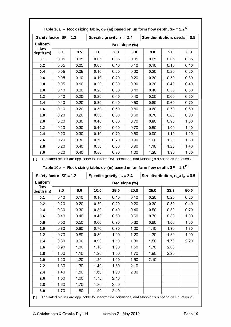
Table 10a – Rock sizing table, d50 (m) based on uniform flow depth, SF = 1.2 [1]
Safety factor, SF = 1.2 Specific gravity, sr = 2.4 Size distribution, d50/d90 = 0.5
Bed slope (%)Uniformflow
depth (m) 0.1 0.5 1.0 2.0 3.0 4.0 5.0 6.0
0.1 0.05 0.05 0.05 0.05 0.05 0.05 0.05 0.050.2 0.05 0.05 0.05 0.10 0.10 0.10 0.10 0.100.4 0.05 0.05 0.10 0.20 0.20 0.20 0.20 0.200.6 0.05 0.10 0.10 0.20 0.20 0.30 0.30 0.300.8 0.05 0.10 0.20 0.30 0.30 0.30 0.40 0.401.0 0.10 0.20 0.20 0.30 0.40 0.40 0.50 0.501.2 0.10 0.20 0.20 0.40 0.40 0.50 0.60 0.601.4 0.10 0.20 0.30 0.40 0.50 0.60 0.60 0.701.6 0.10 0.20 0.30 0.50 0.60 0.60 0.70 0.801.8 0.20 0.20 0.30 0.50 0.60 0.70 0.80 0.902.0 0.20 0.30 0.40 0.60 0.70 0.80 0.90 1.002.2 0.20 0.30 0.40 0.60 0.70 0.90 1.00 1.102.4 0.20 0.30 0.40 0.70 0.80 0.90 1.10 1.202.6 0.20 0.30 0.50 0.70 0.90 1.00 1.20 1.302.8 0.20 0.40 0.50 0.80 0.90 1.10 1.20 1.403.0 0.20 0.40 0.50 0.80 1.00 1.20 1.30 1.50
[1] Tabulated results are applicable to uniform flow conditions, and Manning’s n based on Equation 7.
Table 10b – Rock sizing table, d50 (m) based on uniform flow depth, SF = 1.2 [1]
Safety factor, SF = 1.2 Specific gravity, sr = 2.4 Size distribution, d50/d90 = 0.5
Bed slope (%)Uniformflow
depth (m) 8.0 9.0 10.0 15.0 20.0 25.0 33.3 50.0
0.1 0.10 0.10 0.10 0.10 0.10 0.20 0.20 0.200.2 0.20 0.20 0.20 0.20 0.20 0.30 0.30 0.400.4 0.30 0.30 0.30 0.40 0.40 0.50 0.50 0.700.6 0.40 0.40 0.40 0.50 0.60 0.70 0.80 1.000.8 0.50 0.50 0.60 0.70 0.80 0.90 1.00 1.301.0 0.60 0.60 0.70 0.80 1.00 1.10 1.30 1.601.2 0.70 0.80 0.80 1.00 1.20 1.30 1.50 1.901.4 0.80 0.90 0.90 1.10 1.30 1.50 1.70 2.201.6 0.90 1.00 1.10 1.30 1.50 1.70 2.001.8 1.00 1.10 1.20 1.50 1.70 1.90 2.202.0 1.20 1.20 1.30 1.60 1.90 2.102.2 1.30 1.30 1.40 1.80 2.102.4 1.40 1.50 1.60 1.90 2.302.6 1.50 1.60 1.70 2.102.8 1.60 1.70 1.80 2.203.0 1.70 1.80 1.90 2.40
[1] Tabulated results are applicable to uniform flow conditions, and Manning’s n based on Equation 7.

© Catchments & Creeks Pty Ltd Version 2 - May 2010 Page 11
Table 11a – Preferred rock sizing table, d50 (m) based on unit flow rate, SF = 1.5 [1]
Safety factor, SF = 1.5 Specific gravity, sr = 2.4 Size distribution, d50/d90 = 0.5
Bed slope (%)Unit flowrate
(m3/s/m) 0.1 0.5 1.0 2.0 3.0 4.0 5.0 6.0
0.2 0.05 0.05 0.05 0.10 0.10 0.10 0.10 0.100.4 0.05 0.05 0.10 0.10 0.20 0.20 0.20 0.200.6 0.05 0.10 0.10 0.20 0.20 0.20 0.20 0.300.8 0.05 0.10 0.20 0.20 0.20 0.20 0.30 0.301.0 0.10 0.10 0.20 0.20 0.30 0.30 0.30 0.302.0 0.10 0.20 0.20 0.30 0.40 0.40 0.50 0.503.0 0.20 0.20 0.30 0.40 0.50 0.50 0.60 0.604.0 0.20 0.30 0.40 0.50 0.60 0.60 0.70 0.805.0 0.20 0.30 0.40 0.50 0.60 0.70 0.80 0.906.0 0.20 0.30 0.40 0.60 0.70 0.80 0.90 1.007.0 0.30 0.40 0.50 0.70 0.80 0.90 1.00 1.108.0 0.30 0.40 0.50 0.70 0.90 1.00 1.10 1.209.0 0.30 0.40 0.60 0.80 0.90 1.10 1.20 1.30
10.0 0.30 0.50 0.60 0.80 1.00 1.10 1.20 1.4015.0 0.40 0.60 0.80 1.10 1.30 1.50 1.60 1.8020.0 0.50 0.70 0.90 1.30 1.50 1.80 1.90 2.10
[1] Tabulated results are applicable to uniform flow conditions only.
Table 11b – Preferred rock sizing table, d50 (m) based on unit flow rate, SF = 1.5 [1]
Safety factor, SF = 1.5 Specific gravity, sr = 2.4 Size distribution, d50/d90 = 0.5
Bed slope (%)Unit flowrate
(m3/s/m) 8.0 9.0 10.0 15.0 20.0 25.0 33.3 50.0
0.2 0.20 0.20 0.20 0.20 0.20 0.20 0.30 0.300.4 0.20 0.20 0.20 0.30 0.30 0.40 0.40 0.500.6 0.30 0.30 0.30 0.40 0.40 0.40 0.50 0.600.8 0.30 0.30 0.40 0.40 0.50 0.50 0.60 0.701.0 0.40 0.40 0.40 0.50 0.60 0.60 0.70 0.802.0 0.60 0.60 0.60 0.70 0.80 0.90 1.10 1.303.0 0.70 0.80 0.80 1.00 1.10 1.20 1.40 1.704.0 0.90 0.90 1.00 1.20 1.30 1.50 1.70 2.005.0 1.00 1.00 1.10 1.30 1.50 1.70 1.90 2.306.0 1.10 1.20 1.20 1.50 1.70 1.90 2.207.0 1.20 1.30 1.40 1.70 1.90 2.108.0 1.30 1.40 1.50 1.80 2.109.0 1.40 1.50 1.60 1.90 2.20
10.0 1.50 1.60 1.70 2.1015.0 2.00 2.10 2.2020.0 2.40
[1] Tabulated results are applicable to uniform flow conditions only.
© Catchments & Creeks Pty Ltd Version 2 - May 2010 Page 12
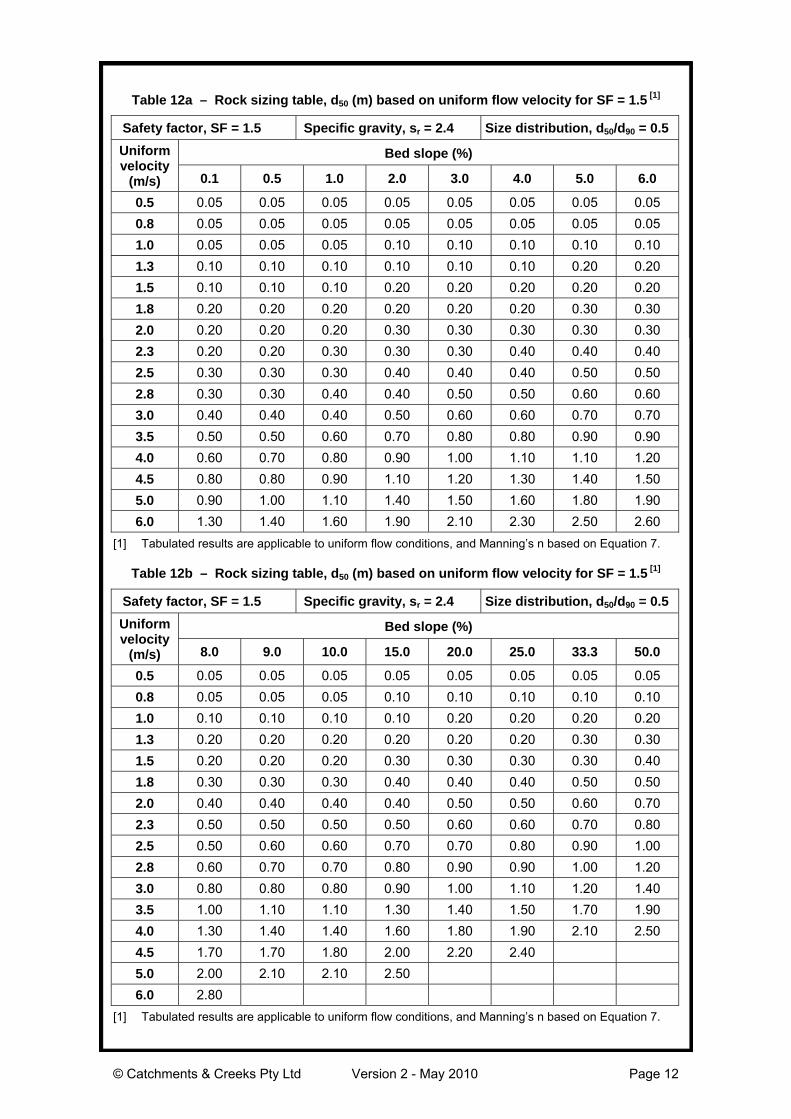
Table 12a – Rock sizing table, d50 (m) based on uniform flow velocity for SF = 1.5 [1]
Safety factor, SF = 1.5 Specific gravity, sr = 2.4 Size distribution, d50/d90 = 0.5
Bed slope (%)Uniformvelocity
(m/s) 0.1 0.5 1.0 2.0 3.0 4.0 5.0 6.0
0.5 0.05 0.05 0.05 0.05 0.05 0.05 0.05 0.050.8 0.05 0.05 0.05 0.05 0.05 0.05 0.05 0.051.0 0.05 0.05 0.05 0.10 0.10 0.10 0.10 0.101.3 0.10 0.10 0.10 0.10 0.10 0.10 0.20 0.201.5 0.10 0.10 0.10 0.20 0.20 0.20 0.20 0.201.8 0.20 0.20 0.20 0.20 0.20 0.20 0.30 0.302.0 0.20 0.20 0.20 0.30 0.30 0.30 0.30 0.302.3 0.20 0.20 0.30 0.30 0.30 0.40 0.40 0.402.5 0.30 0.30 0.30 0.40 0.40 0.40 0.50 0.502.8 0.30 0.30 0.40 0.40 0.50 0.50 0.60 0.603.0 0.40 0.40 0.40 0.50 0.60 0.60 0.70 0.703.5 0.50 0.50 0.60 0.70 0.80 0.80 0.90 0.904.0 0.60 0.70 0.80 0.90 1.00 1.10 1.10 1.204.5 0.80 0.80 0.90 1.10 1.20 1.30 1.40 1.505.0 0.90 1.00 1.10 1.40 1.50 1.60 1.80 1.906.0 1.30 1.40 1.60 1.90 2.10 2.30 2.50 2.60
[1] Tabulated results are applicable to uniform flow conditions, and Manning’s n based on Equation 7.
Table 12b – Rock sizing table, d50 (m) based on uniform flow velocity for SF = 1.5 [1]
Safety factor, SF = 1.5 Specific gravity, sr = 2.4 Size distribution, d50/d90 = 0.5
Bed slope (%)Uniformvelocity
(m/s) 8.0 9.0 10.0 15.0 20.0 25.0 33.3 50.0
0.5 0.05 0.05 0.05 0.05 0.05 0.05 0.05 0.050.8 0.05 0.05 0.05 0.10 0.10 0.10 0.10 0.101.0 0.10 0.10 0.10 0.10 0.20 0.20 0.20 0.201.3 0.20 0.20 0.20 0.20 0.20 0.20 0.30 0.301.5 0.20 0.20 0.20 0.30 0.30 0.30 0.30 0.401.8 0.30 0.30 0.30 0.40 0.40 0.40 0.50 0.502.0 0.40 0.40 0.40 0.40 0.50 0.50 0.60 0.702.3 0.50 0.50 0.50 0.50 0.60 0.60 0.70 0.802.5 0.50 0.60 0.60 0.70 0.70 0.80 0.90 1.002.8 0.60 0.70 0.70 0.80 0.90 0.90 1.00 1.203.0 0.80 0.80 0.80 0.90 1.00 1.10 1.20 1.403.5 1.00 1.10 1.10 1.30 1.40 1.50 1.70 1.904.0 1.30 1.40 1.40 1.60 1.80 1.90 2.10 2.504.5 1.70 1.70 1.80 2.00 2.20 2.405.0 2.00 2.10 2.10 2.506.0 2.80
[1] Tabulated results are applicable to uniform flow conditions, and Manning’s n based on Equation 7.

© Catchments & Creeks Pty Ltd Version 2 - May 2010 Page 13
Table 13a – Rock sizing table, d50 (m) based on uniform flow depth, SF = 1.5 [1]
Safety factor, SF = 1.5 Specific gravity, sr = 2.4 Size distribution, d50/d90 = 0.5
Bed slope (%)Uniformflow
depth (m) 0.1 0.5 1.0 2.0 3.0 4.0 5.0 6.0
0.1 0.05 0.05 0.05 0.05 0.05 0.05 0.10 0.100.2 0.05 0.05 0.05 0.10 0.10 0.10 0.20 0.200.4 0.05 0.10 0.10 0.20 0.20 0.20 0.30 0.300.6 0.05 0.10 0.20 0.20 0.30 0.30 0.40 0.400.8 0.10 0.20 0.20 0.30 0.40 0.40 0.50 0.501.0 0.10 0.20 0.20 0.30 0.40 0.50 0.60 0.601.2 0.10 0.20 0.30 0.40 0.50 0.60 0.70 0.701.4 0.20 0.20 0.30 0.50 0.60 0.70 0.80 0.801.6 0.20 0.30 0.40 0.50 0.70 0.80 0.90 0.901.8 0.20 0.30 0.40 0.60 0.70 0.80 1.00 1.002.0 0.20 0.30 0.40 0.60 0.80 0.90 1.10 1.202.2 0.20 0.30 0.50 0.70 0.90 1.00 1.20 1.302.4 0.20 0.40 0.50 0.80 1.00 1.10 1.30 1.402.6 0.20 0.40 0.60 0.80 1.00 1.20 1.40 1.502.8 0.30 0.40 0.60 0.90 1.10 1.30 1.50 1.603.0 0.30 0.40 0.60 0.90 1.20 1.40 1.60 1.70
[1] Tabulated results are applicable to uniform flow conditions, and Manning’s n based on Equation 7.
Table 13b – Rock sizing table, d50 (m) based on uniform flow depth, SF = 1.5 [1]
Safety factor, SF = 1.5 Specific gravity, sr = 2.4 Size distribution, d50/d90 = 0.5
Bed slope (%)Uniformflow
depth (m) 8.0 9.0 10.0 15.0 20.0 25.0 33.3 50.0
0.1 0.10 0.10 0.10 0.10 0.20 0.20 0.20 0.200.2 0.20 0.20 0.20 0.20 0.30 0.30 0.30 0.400.4 0.30 0.30 0.30 0.40 0.50 0.50 0.60 0.800.6 0.40 0.50 0.50 0.60 0.70 0.80 0.90 1.100.8 0.60 0.60 0.60 0.80 0.90 1.00 1.20 1.501.0 0.70 0.70 0.80 1.00 1.10 1.30 1.50 1.801.2 0.80 0.90 0.90 1.20 1.30 1.50 1.80 2.201.4 1.00 1.00 1.10 1.30 1.60 1.80 2.001.6 1.10 1.20 1.20 1.50 1.80 2.001.8 1.20 1.30 1.40 1.70 2.002.0 1.40 1.40 1.50 1.90 2.202.2 1.50 1.60 1.70 2.102.4 1.60 1.70 1.80 2.302.6 1.70 1.90 2.002.8 1.90 2.003.0 2.00
[1] Tabulated results are applicable to uniform flow conditions, and Manning’s n based on Equation 7.

© Catchments & Creeks Pty Ltd Version 2 - May 2010 Page 14
Table 14a – Alternative design table for mean rock size for specific gravity, sr = 2.6 [1]
Safety factor, SF = 1.5 Specific gravity, sr = 2.6 Size distribution, d50/d90 = 0.5
Bed slope (%)Uniformflow
depth (m) 0.1 0.5 1.0 2.0 3.0 4.0 5.0 6.0
0.1 0.05 0.05 0.05 0.05 0.05 0.05 0.05 0.100.2 0.05 0.05 0.05 0.10 0.10 0.10 0.10 0.200.4 0.05 0.05 0.10 0.20 0.20 0.20 0.20 0.300.6 0.05 0.10 0.20 0.20 0.30 0.30 0.30 0.400.8 0.10 0.10 0.20 0.30 0.30 0.40 0.40 0.501.0 0.10 0.20 0.20 0.30 0.40 0.40 0.50 0.601.2 0.10 0.20 0.30 0.40 0.50 0.50 0.60 0.701.4 0.10 0.20 0.30 0.40 0.50 0.60 0.70 0.801.6 0.20 0.20 0.30 0.50 0.60 0.70 0.80 0.901.8 0.20 0.30 0.40 0.50 0.70 0.80 0.90 1.002.0 0.20 0.30 0.40 0.60 0.70 0.80 1.00 1.102.2 0.20 0.30 0.40 0.60 0.80 0.90 1.00 1.202.4 0.20 0.30 0.50 0.70 0.90 1.00 1.10 1.302.6 0.20 0.40 0.50 0.70 0.90 1.10 1.20 1.402.8 0.20 0.40 0.50 0.80 1.00 1.20 1.30 1.503.0 0.20 0.40 0.60 0.90 1.10 1.20 1.40 1.60
[1] Tabulated results are applicable to uniform flow conditions, and Manning’s n based on Equation 7.
Table 14b – Alternative design table for mean rock size for specific gravity, sr = 2.6 [1]
Safety factor, SF = 1.5 Specific gravity, sr = 2.6 Size distribution, d50/d90 = 0.5
Bed slope (%)Uniformflow
depth (m) 8.0 9.0 10.0 15.0 20.0 25.0 33.3 50.0
0.1 0.10 0.10 0.10 0.10 0.10 0.20 0.20 0.200.2 0.20 0.20 0.20 0.20 0.20 0.30 0.30 0.400.4 0.30 0.30 0.30 0.40 0.40 0.50 0.60 0.700.6 0.40 0.40 0.50 0.60 0.60 0.70 0.80 1.000.8 0.50 0.60 0.60 0.70 0.80 0.90 1.10 1.301.0 0.60 0.70 0.70 0.90 1.00 1.20 1.30 1.701.2 0.80 0.80 0.90 1.10 1.20 1.40 1.60 2.001.4 0.90 0.90 1.00 1.20 1.40 1.60 1.90 2.301.6 1.00 1.10 1.10 1.40 1.60 1.80 2.101.8 1.10 1.20 1.30 1.60 1.80 2.002.0 1.20 1.30 1.40 1.70 2.002.2 1.30 1.40 1.50 1.90 2.202.4 1.50 1.60 1.70 2.102.6 1.60 1.70 1.80 2.202.8 1.70 1.80 1.90 2.403.0 1.80 1.90 2.10
[1] Tabulated results are applicable to uniform flow conditions, and Manning’s n based on Equation 7.
© Catchments & Creeks Pty Ltd Version 2 - May 2010 Page 15
Description
The rock lining of drainage channels,chutes and spillways. The rock can be leftuncovered (open voids), or lightly coveredwith soil and pocket planted (closed voids).
Purpose
Scour protection of the bed and banks ofdrainage channels, chutes, and spillways.
Most commonly used when flow velocitiesare expected to be high.
Also used in arid areas where a goodvegetation cover cannot be expected.
Limitations
In some circumstances, long-term successoften depends on the introduction ofsuitable vegetation to anchor the rocks.
Rock should not be placed directly ondispersive soils. A layer of non-dispersivesoil must be placed over the dispersive soilbefore placement of the rock.
Advantages
One of the most common and inexpensiveforms of channel lining.
The porous nature of the rock can protectthe channel from uplift—a problemassociated with impervious concrete linings.
Does not necessarily require a well-formedchannel cross section—as is the case forsome forms of channel lining.
The surface can be fully vegetated toproduce a natural channel appearance.
Disadvantages
Problems can occur due to infestation byrodents and unsightly weeds if the voidsremain open.
Rock-lined chutes are most susceptible todamage during the first few years afterconstruction.
Common Problems
Severe erosion problems if rocks areplaced directly on dispersive soil. To reducethe potential for such problems, dispersivesoils should be covered with a minimum200mm layer of non-dispersive soil beforerock placement.
Failure of rock-lined chutes due to theabsence of a suitable filter cloth oraggregate filter layer beneath the primaryarmour rock layer.
Circumstances where a filter layer may notbe required include:• rock placed on a very mild slope where
flow velocities are expected to be low;• rock placement where the voids are
filled with soil and pocket planted.
The latter case is most appropriate whenrock protection is used on waterways andpermanent rock chutes.
Weed invasion of the rock protection canbecome unsightly. The control of weedgrowth can be an expensive, labourintensive exercise.
Special Requirements
An underlying geotextile or rock filter layeris generally required unless all voids arefilled with soil and pocket planted (thuspreventing the disturbance and release ofunderlying sediments through these voids).
The upper rock surface should blend withsurrounding land to allow water to freelyenter the channel.
It can be difficult to de-silt a rock linedchannel, so permanent rock-lined channelsmay need to be protected from sedimentinflow while construction works continue up-slope of the channel.
Site Inspection
Check for excessive vegetation growth thatmay restrict the channel capacity.
Check the thickness of rock application andthe existence of underlying filter layer.
Check for erosion around the outer edgesof the treated area.
Ensure the rock size and shape agrees withapproved plan.
Materials
• Rock: hard, angular, durable, weatherresistant and evenly graded with 50%by weight larger than the specifiednominal rock size and sufficient smallrock to fill the voids between the largerrock. The diameter of the largest rocksize should be no larger than 1.5 timesthe nominal rock size. Specific gravityto be at least 2.5.
• Geotextile fabric: heavy-duty, needle-punched, non-woven filter cloth,minimum ‘bidim’ A24 or equivalent.

© Catchments & Creeks Pty Ltd Version 2 - May 2010 Page 16
Installation
1. Refer to approved plans for location,extent and installation details. If thereare questions or problems with thelocation, extent, or method ofinstallation contact the engineer orresponsible on-site officer forassistance.
2. Clear the proposed channel area oftrees, stumps, roots, loose rock, andother objectionable materials.
3. Excavate the channel to the lines andgrades as shown on the plans. Over-cutthe channel to a depth equal to thespecified depth of rock placement suchthat the finished rock surface will be atthe elevation of the surrounding land.
4. Rock must be placed within the channelas specified within the approved plans,including the placement of anyspecified filter layer.
5. If details are not provided on the rockplacement, then the primary armourrock must be either placed on:
• a filter bed formed from a layer ofspecified smaller rock (rock filter layer);
• an earth bed lined with filter cloth;• an earth bed not lined in filter cloth, but
only if all voids between the armourrock are to be filled with soil and pocketplanted immediately after placement ofthe rock.
6. If a rock/aggregate filter layer isspecified, then place the filter layerimmediately after the foundations areprepared. Spread the filter rock in auniform layer to the specified depth buta minimum of 150mm. Where morethan one layer of filter material hasbeen specified, spread each layer suchthat minimal mixing occurs betweeneach layer of rock.
7. If a geotextile (filter cloth) underlay isspecified, place the fabric directly onthe prepared foundation. If more thanone sheet of fabric is required to overthe area, overlap the edge of eachsheet at least 300mm and place anchorpins at minimum one metre spacingalong the overlap.
8. Ensure the geotextile fabric is protectedfrom punching or tearing duringinstallation of the fabric and the rock.Repair any damage by removing therock and placing with another piece offilter cloth over the damaged areaoverlapping the existing fabric aminimum of 300mm.
9. Where necessary, a minimum 100mmlayer of fine gravel, aggregate or sandshould be placed over the fabric toprotect it from damage.
10. Placement of rock should followimmediately after placement of the filterlayer. Place rock so that it forms adense, well-graded mass of rock with aminimum of voids.
11. Place rock to its full thickness in oneoperation. Do not place rock bydumping through chutes or othermethods that cause segregation of rocksizes.
12. The finished surface should be free ofpockets of small rock or clusters oflarge rocks. Hand placing may benecessary to achieve the properdistribution of rock sizes to produce arelatively smooth, uniform surface. Thefinished grade of the rock should blendwith the surrounding area. No overfallor protrusion of rock should beapparent.
13. Immediately upon completion of thechannel, vegetate all disturbed areas orotherwise protect them against soilerosion.
14. Where specified, fill all voids with soiland vegetate the rock surface inaccordance with the approved plan.
Maintenance
1. Rock-lined channels should beinspected periodically and aftersignificant storm events. Check forscour or dislodged rock. Repairdamaged areas immediately.
2. Closely inspect the outer edges of therock protection. Ensure water entry intothe channel or chute is not causingerosion along the edge of the rockprotection.
3. Carefully check the stability of the rocklooking for indications of piping, scourholes, or bank failures.
4. Replace any displaced rock with rock ofa significantly (minimum 110%) largersize than the displaced rock.