rocket motors, m5, m5e1, and m88, metal...
TRANSCRIPT

MIL–R-46468A(MI)1! OCTOBER 1962
SUPERSEDINGMIL-R-46466(ORD)31DECEMBER 1960
MILITARY SPECIFICATION
ROCKET MOTORS, M5, M5E1, AND M88,METAL PARTS FOR
1. .SCOPE
1.1. “This specification sets forth require-ments for the metal parts for three types ofreeket motors.
‘1.2. Cksk%ation. The rocket motors shallbe of, the following types as specified:
Type I—M5 Rocket Motor Metal PartsAssembly
,, ....Type 11—M5E1 Recket Motor MetaiParts Assembly
“’I$pe 111-M88 Rocket Motor MetalParts Assembly
2. APPLICABLE DOCUMENTS
2 . 1The following documents of the issuein effect ‘on date of invitation for lids form ap@ of this specification to the extent speci-fied herein.
SPECIFICATIONS
FmmamQQ=571 -Solder: Lead AUoy, Tin
Lead Alloy, and T1nAf-,,10Y: Flnx Cored Rib-km and Wire, and
,) . Solid Form-Q‘PP-P-664 —Primer, Coating, Syn-,. thetic, Rust Inhibiting,,., , Lacquer Resisting
MILITARY
~ :. MI&P–116 —Preservation, Methods ofMII_-V-173 —Varnish, Moisture and,.,1, Fungus-Resistant for
,. the Treatment of Com-
munications, Electron-ic, and Associated Elec-trical Equipment
MIL-A-2550-General Specification forAmmunition, ExceptSmall Arms Ammuni-tion
MILI-6865 —Inspection, RadiographMH.A-6868 —Inspection Process, Mag-
netic Particle -MIL-S-6872 -soldering Process, Gen-
eral Specification forMIL-W– —Welding, Flash, Carbon
6873 and AROYSteelMIL-H-6875-Heat Treatment of Steels
(Air-Craft Practice)Process for
MIf_-W- —Welding, Metal Arc and8611 Gas, Steels and Cor-
rosion and Heat Resist-ant Alloys: Process for
MIL-R- —Radiographic Inspection,11468 Soundness Require-
ment for Arc and GasWelds in Steel
MILM- —Magnetic-Particle Inspec-11473 tion; Soundness Re-
quirements for Weld-ments
STANDARDS
FEDERAL
FED-STD- —Metals, Test Method151
m
Downloaded from http://www.everyspec.com

I
MIL-R-46468A (MI)
MILITARYMIIATD– —Sampling Procedures and
1 0 5 Tables For Inspectionby Attributes
MIL-STD– —Marking for Shipment129 and Storage
MIL-STD– —Identification Marking130 for U.S. Military Prop-
ertyMIL-STD– —Preparation, Painting,
171 and Finishing forMetal and Wood Sur-faces
DRAWINGS
ORONANCECORPS8025074 —Rocket Motor, M5, Metal
Parts Assembly8030046 —Rocket Motor, M5E1,
Metal Parts Assembly8080062 —Crate, Wood, Jato M13
Al Assembly and De-tails
8030810 —Rocket Motor, M88, MetalParts Assembly
(Copiesofspecifications,standards,and drawingsrequired by contractors in connection with specificprocurement fwctions should be obtained from theprocuring activity or as directed by the contractingofficer. )
2.2 Other publications. The following docu-ment forms a part of this specification to theextent specified herein. Unless otherwise in-dicated, the issue in effect on date of invita-tion for bids shall apply.
CODEOFFRDERALREGULATIONS49 CFR 71–90-Interstate Commerce
Commission, Rulesand Regulations forthe Transportation ofExplosives and OtherDangerous Articles
(Applicationfor copiesshouldb+addressedto theSuperintendentof Documents,GovernmentPrintingOffice,Washington25,D.C.Otiers for copiesshoulacite “49 GFR71-90 (Revised,1956)1,.)
3. REQUIREMENTS
3.1 Applicability. Unless otherwise indi-cated, all requirements, examination, and
2
tests specified herein shall be applicable toType I, Type II, and Type III motors (see6.3) .
3.2 Preproduction sample. Unfess other-wise specified (see 6.2), the contractor shallfurnish preproduction samples for preproduc-tion inspection in accordance with 4.3. Thepreproduction samples shall be produced bythe same methods, processes and techniquesto be employed in subsequent production ofthe contract quantity.
3.3 Materials.
3.3.1 Type I. Materials shall be in accord-ante with Drawing 8025074 and applicabledrawings and specifications referenced there-on and as specified herein.
3.3.2 Type ZI. Materials shall be in accord-ante with Drawing 8030046 and applicabledrawings and specifications referenced there-on and as specified herein.
3.3.3 2’~pe121. Materials shall beinaecord-ante with Drawing 8030810 and applicabledrawings and specifications referenced there-on and as specified herein.
3.4 Design.
3.4.1 Type I. Parts and asse@lies shallconform to dimensions, tolerance limits,physical properties and degree of surfaceroughness specified by drawings and specifi-cations referenced on Drawing 8025074.
3.4.2 Type II. Parts and assemblies shallconform to dimensions, tolerance limits,physical properties and degree of. eurfaceronghness specified by drawings and specifi-cations referenced on Drawing 8030046.
3.4.3 Type III. Parts and assemblies shallconform to dimensions, tolerance limits,physical properties and degree of surfaceroughness specified by drawings and specifi-cations referenced on Drawing 8030810.
3.5 Construction.
3.5.1 Type J. Parts andassemblies shall beconstructed in accordance with Drawing8025074 andapplicable drawings and specifi-cations referenced thereon and as specifiedherein.
Downloaded from http://www.everyspec.com

3.5.2 T@@ II. Parts and assemblies shallbe ‘constructed in accordance with Drawing8030046 and applicable drawings and specifi-cations referenced thereon and as specifiedherein.
3.5.3 Type III. Parts and assemblies shallbe constructed in accordance with Drawing8030810 and applicable drawings and specifi-cations referenced thereon and as specifiedherein.
3.5.4 Prope2kwzt ca.w instikztion. The in-terior surface of the propellant case shall belined with an insulating material which hasa low heat transfer coefficient, bonds wellwith metal and does not bond with the cel-lulose acetate restrictive container for thepropellant grain. The insulation shall be“Flamemaatic”, fine, color white, or equal(see 6.4) for the intended purpose.
3.5,4.1 The applied insulation shall be .036inch thick and shall be applied after comple-tion of all tests and within 24 hours aftercleaning the propellant case. In the eventthat the application of the insulation is notfeasible within the prescribed time, the in-terior snrface of the propellant case shall beprotected from corrosion with a materialwhich is compatible with both the case andthe insulation to be applied and otherwisesuitable for the intended purpose. The insula-tion skdI be cured a minimum of 24 hours at180° F. after application to the case interior.
3.5.5 WeMing. Welding shall be arc processin accordance with Specification MILW-8611 except that the ring specified on Draw-ing 8030123, covering a detail of Drawings8025074, 8030046, and 8030810, may be flashwelded in accordance with Specification MILW–6873. Weld beads shall be not more than3/32 inch high. Weldments shall be stressrelieved.
3.5.6 SoZdering. (Types I and II). Solder-ing shall be performed in accordance withSpecification MIL-S-6872, using solder con-forming to Specification QQ-S-571, Clsss A,Comp-SN-50.
3.5.7 Heat trwtwtent. Parts requiring heattreatment shall be heat treated to the hard-
MIL-R-4&14i8A(MI)
ness ratings specified on the applicable draw-ings in accordance with Specifkation MIL-IL8375.
3.6 Performance and product character-i8tice.
3.6.1 Rocket ?noto~ bod~ rrseembt~. Eachbody assembly shall withstand an internalhydrostatic pressure of 1,575 pounds persquare inch (psi) for a period of 3 minuteswithout leakage, rupture or distortion of con-figuration in excess of tolerances specifiedon the applicable drawings.
3.6.2 Sor.malaese requkwwmts of weld-mente. Weldmenta shall meet the soundnessrequirements of Specifications MIL-R-11468,Standard I, and MIL-M-11473.
3.7 Pretreatment and protective finish. Un-less otherwise specified on detail drawings,preparation and finish of metal surfaces shallbe as follows:
3.7.1 Pretreatwertt. All metal surfacesshall be cleaned and treated, prior to finish-ing, in accordance with Standard MIfX3TD–171, Finish No. 4.1 and 5.1.
3.7.2 Protective finish. A protective finishconf orrning to Standard MIL-STD-171, Sys-tem 20.5 shall be applied to all metal surfacesexcept as follows:
3.7.2.1 Threads and mating ewrfaces.Threads and mating surfaces shall be keptfree of finishing materials.
3.7.2.2 Zwte&or no?wnating surfaces. A watof primer conforming to Specification TT–P–664 shall be applied to all interior non-mating surfaces except the nozzle area aftof the point of smallest diameter of the exitnozzle throat.
3.7.2.3 Soldered connections. (Types I andII). A coat of varnish conforming to Specifi-cation MIL-V-173 shall be applied to allsoldered connections.
3.8 Marking.
3.8.1 Product marking. Parts and assem-blies shall be marked for identification inaccordance with Staudard MII&TD-130.
3
Downloaded from http://www.everyspec.com

MIGR-%468A(MI )“
3.8.2 Special marking. Upon satisfactorycompletion of hydrostatic pressure tests, ‘thebody assembly shall be marked with the letter“H” and shall be impressed in the locationspecified on Drawing 8030044, covering a de-tail of Drawings 8025074, and 8030046 andas specified on Drawing 8030809, covering adetail of Drawing 8030810, respectively.
3.9 Workrnanshlp. Assemblies and partsshall be free. of dirt, grease, chips, rust orother foreign matter. There shall be nocracks, bends, breaks, dents, grooves or otherdefects which would make any part or assem-bly unsuitable for the intended purpose. Theworkmanship shall be of such quality thatWi]l insure uniformity of perforrnmce andinterchangeability of parts and asaemblieahaving the same part numbers.
4. QUALITY ASSURANCE PROVISIONS
4.1 The supplier is responsible for perform-ance of all inspection requirements ae. speci-fied herein. Except aa otherwise specified, thesupplier may utilize h]s own or any other in-spection facilities and services acceptable tothe Government. Inspection records of theexamination and tests shall be kept completeand available to the Government as specifiedin the contract or order. Tlie Governmentreserves the right to perform any of the in-spections set forth in the specification wheresuch inspections are deemed necessary to ae-sure suppfies and services conform to pre-scribed requirements.
4.2 Lot size. A lot of metal parts for TypesI, II, or III Rocket Motors shzfl consist of thatquantity produced in uot more than 24 hoursof continuous production with no change infacilities, process or specifications whichwould change the chemical and physical prop-erties or interchangeability of the parts with-in like motors.
4.3 Preprodnction provisions.
4.3.1 Sample. Unless otherwise specified, asample shall consist of one complete metalparts assembly of Type I, II or III RocketMotor, as specified in the contract or order.
4.3.2 Inspection location. Preproduction in-
4
spection shall be performed by tlie ‘Govern-ment at a place specified by the procurintiactivity (see 6.2).
4.3.3 Inspection. The sample specified. in4.3.1 shall be subjected to the examinationand tests specified in 4.4.2.
4.4 Production provisions.
4.4.1 Sampling.
4.4.1.1 For examination. Sampling for ex-amination shall be in accordance with Stand-ard MIL-STD-105 at inspection level If, A!so,at the option of the procuring, actw@,AQL’s and sampling plans may be applied tothe individual characteristics listed, using anAQL of 0.25 percent for each major defectand 0.40 percent for each minor defect.
4.4.1.2 Test eamr.ies. All parts, welds, andbody assemblies shall be subjected to theteats as specified herein.
4.4.2 Inspection.
4.4.2.1 Ezami?wtion. Examination of thesamples selected in 4,4.1.1 shall be in accord:ante with classification of defects as follows:
4.4.2.1.1 CkweWxction of de fecte, ,
4.4.2.1.1.1 Bolt. (Drawing 8025044, c&er-ing a detail of Drawings 8025074 and 80,3-0046; Types I and II, respectively.) ,.
r%:~yD,fe.t8 in$uenaon
AQL 0.40 pensentMajor ,...Threadsize...............Measnre
Overalllength............MezsureLength of taper . . . . . . . . . .. Mezsure
AQL 1.0 percentMinor ,,. .Finish, . . . . . . . . . . . . . . . . . .. Visual
Chamfer . . . . . . . . . . . . . . . . .. Vimsl
4.4.2.1.1.2 O-n”ng. (Drawing 8025016, rev-ering a detail of Drawings 8025074, 8030046,and 8030810; Types 1, 11, and 111,respective-ly.)
AQL 0.25 percentMajor . . . . Inside diameter . . . . . . . . . . . .Meusur@
Thickness ... . . . . . . . . . . . . .. Measinm
Downloaded from http://www.everyspec.com
MIL-R46468A(MI)
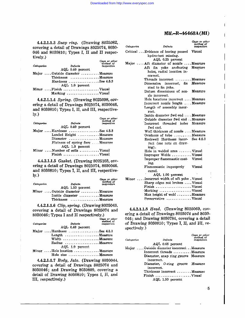
4.4.2.1.1.3 .%uzp ting. (Drawing 8025082,covering a detail of Drawings 8025074, 8030-046 and 8030810; Types I, II and II respec-tively.)
G~~L~;~Ca.om.ea Defeda i.w..tio.t
AQL 0.40 percentMajor . . . . Outside diameter . . . . . . . . . .Measure
Thickness . . . . . . . . . . . . . . .. MeasureHardness . . . . . . . . . . . . . . . .. Sse4.&3
AQL 1.0 percentMinor . . .. Finish . . . . . . . . . . . . . . . . . . .. Visual
Marking . . . . . . . . . . . . . . . . .. VisuaI
4.4.2.1.1.4 SptinO. (Drawing 8025098, cov-ering a detail of Drawings 30250’74, 8030046,and 8030810; Types I, II, and III, respective-ly’.)
Cdamwkn.AQL 0.40 percent
Major . . . . Hardness . . . . . . . . . . . . . . . .. See 4.6.3Loaded Height . . . . . . . . . . ..MeasureDiameter . . . . . . . . . . . . . . . .. MeasureFlatness of spring face . . .. Measure
AQL 1.0 percentMinor . . .. Number of coils . . . . . . . . . .. Visual
Finish . . . . . . . . . . . . . . . . . . ..Visual
4.4.2.1.1.5 Ga&et. (Drawing 8025103, cov-ering a detail of Drawings 8025074, 8030046,and 8030810; Types 1,11, andlII, respective-ly.)
a::t=:yCatega.i.. Def@a insw.tikm
AQL 1.50percentMinor . . .. Outside diameter . . . . . . . . .. Measure
Inside diameter . . . . . . . . . .. MeasureThickness . . . . . . . . . . . . . . .. Measure
4.4.2.1.1.6 C@,spring.(D rawing8025043,covering a detail of Drawings 8025074 and8030046; Types I and II respectively.)
AQL 0.40 percentMajor . . .. Hardness . . . . . . . . . . . . . . . .. SW4.6.3
Length . . . . . . . . . . . . . . . . . ..MeasureWidth . . . . . . . . . . . . . . . . . . .. MeasureRadius . . . . . . . . . . . . . . . . . .. Mea8ure
AQL 1.0 percentMinor . . .. Hole location . . . . . . . . . . . . .. Measure
Hole size . . . . . . . . . . . . . . . ..Measure
4,4.2.1.1.7 Body, Jato. (Drawing 8030044,covering a detail of Drawings 8025074 and8030046; and Drawing 8030809, covering adetail of Drawing 8030810; Types I, II, andIII, respectively.)
c.t.mrie. Defect,
Critical . .. Evidence of having passed Visualhydro-test missing.
AQL 0.25 percentMajor . . .. Aft diameter of nozzle . . .. Measure
Aft fin yoke anchoring Measureholes, radial location in-correct.
Threads incorrect . . . . . . . .. MeasureDimension incorrect, fin Measure
stud to fin yoke,Datum dimensions of noz- Measure
zle incorrect.Hole locations incorrect . . .. MeasureIncorrect nozzle Iengtb . . ..lleasoreLength of assembly incor-
rect.Inside diameter fwd end ,.. .MeasoreOutside diameterfwd end .. Measure‘Incorrect threaded holes Measure
fwd end.Wall thickness of nozzle ..: Measure‘Ovabmssoftube . . . . . . . . ..MeasureRockwell Hardness incor- See 4.5.3
rect (see note on draw-ing).
Hole in welded area . . . . . .. VisualImIIrouer Welds . . . . . . . . . .. VisuaIImpro~er flamemasticcoa& Visual
ing.
Flamema8tic improperly Visualcured.
AQL 1.00 percentMinor . . .. Incorrect width of aft yoke .Visual
Sharp edges not broken . . .. VisualFinish . . . . . . . . . . . . . . . . . . .. VisualMarking. . . . . . . . . . . . . . . . .. VisualMaxheigbtof weId . . . . . . .. MeaSorePresemative . . . . . . . . . . . . .. Visual
4.4.2.1.1.8 Head, (Drawing 8025069, cov-ering a detail of Drawings 8025074 and 8030-046; and Drawing 8030784, covering a detailof Drawing 8030810; Types I, II, and III, re-spectively. )
AQL 0.66 percentMajor .,. ,Outside diameter incorrect .. Measure
Incorrect threads . . . . . . . . .. MeasureDiameter, snap ring groove Measure
incorrect.Diameter, O-ring groove IMeasure
incorrect.Thickness incorrect . . . . . . .. M&wueFinish . . . . . . . . . . . . . . . . . . .. Visual
AQL 1.60 percent
5
Downloaded from http://www.everyspec.com

MIL-R-46468A(MI)
Minor . . . . Sutiace finish not met . . . . .VisualMarking missing..........VisualBurrs or sharp edgesnot Visualremoved.
4.4.2.1.1.9 Harness o..wembly. (DrawingS030004, covering a detail of Drawings 802-5074 and 8030046; Types I and 11,respective-ly.)
Defeot.
G... m other,Mthc,f oft.m..tio>,
AQL 0.65 percentMajcit . . . . Continuity failure . . . . . . . . .Voltmeter
Inmlation not molded into Vismlplug.
Length incorrect . . . . . . . .MeasureLoose components . . . . . . . . . Man”alPhcz size incorrect . . . . . . . . Merumre
AQL 1.00 nercentMinor . . . . Plug location incorrect . . . . Meamre
Marking missing . . . . . . . . . .Visual
4.4.2.1.1.10 Closwe, shipping. (Drawing8030837, covering a detail of Drawings 802-5074, 8030046 and 8030S10; Types I, II, andHI, respectively.)
(7.,. ., othermethod of
ca&?Ol&. Defeot. ins?.ctkmAQL 0.40 percent
Major . . . . Threads incorrect . . . . . . . MeamreOutside diameter incorrect MeasmeDepth of holes incorrect . . . Measme
AQ1. 2.50 percentMinor . . .. ColOr incorrect . . . . . . . . . . .. Visual
Not opaque . . . . . . . . . . . . . .. VisualShoulder thickness incor- Measmw
rect.Overall thickness incorrect MeasureMarking incorrect . . . . . . . . .Visual
4.4.2.1.1.11 Rod, resvnance. (Drawing8026087, covering a detail of Drawings 802-5074, 8030046 and 8030810; Types I, II, andIII, respectively.)
GW:t~dO:~
catwwia Defects kqm.tb”AQL 0.40 percent
Major ,.. Component missing Vi.qwdHole locations incorrect MeasmeHod threads incorrect Measure
AQL 1.50 percentMinor . . . . Grommets inadequately win-Visual
pressed.Part number missing . . . . .VisualFinish . . . . . . . . . . . . . . . . . . .. ViwaIRod length incorrect . . . . .Meamre
4.4,2.1.1.12 Closare, noz.de, (Drawing8030041, covering a detail of Drawing 802-5074 and 8030046; and Drawing S030782,covering a detail of Drawing 8030810; TypesI, II, and III, respectively.)
AQL 0.40 percentMajor . . . . Diameter incorrect . . . . . . . . Measure
Inadequate cement . . . . . . . . Man”alCord clip missing (Types Visual
I and Ii).AQL 1.0 percent
Minor . . . . Componentincorrectlyas- Visualsemhled(Type I and11).
Overall length incorrect . . . . Measure
4.4.2.2 Testing.
4.4.2.2.1 Wet&?w%tts. All arc process weld-ments shall be subjected to magnetic particleinspection as specified in 4.5.1, after hydro-static testing. Flash weldments shall bs sub-jected to radiographic inspection as specifiedin 4.5.2.
4.4.2.2.2 Body assemblies. Each bedy ss-sembly shall be subjected to hydrostatic pres-sure test as specified in 4.5.4.
4.4.3 Examination of preservation, pack-ing and marking. Preservation, packing, andmarking shall be examined to determine con-formance with the requirements specified insection 5.
4.5 Tests.
4.5.1 Magnetic particle inWection. Mag-netic particle inspection shall be conductedin accordance with Specification MIL-I-6868.
4.5.2 Radiographic in.spectiwt. Radio-graphic inspection shall be conducted in ac-cordance with Specification MIL-I-6865.
4.5.3 Rockwell kardne$s. Rockwell hard-ness of parts and assemblies shall be deter-mined in accordance with Federal TestMethod Standard 151.
4.5.4 Hydrostatic press-are test. The hydro-static pressure test shall be conducted insuch a manner to insure that the assemblycomponents are free to expand in any direc-tion. There shall elapse at least 48 hours be-tween heat treatment of the components and
6
Downloaded from http://www.everyspec.com

hydrostatic test of the assembly. The aasem-bly shalf be subjected to a pressure of 1,575,plus or minus 10, psi for a peried of 3 min-utes and shall be inspected to determine com-pliance with the requirements of 3.6.1.
4.6 Preservation, packing and marking.Visual and tactile examination of preserva-tion, packing and marking shall be performedto determine compliance with the requhw-ments of section 5.
5. PREPARATION FOR DELIVERY
5.1 Preservation, packing and marking.
5.1.1 Preservation. C1eaning and the appli-cation of preservatives shall be in accordancewith Specification MILP–116.
5.1.1.1 Preservative coating. All cleaned,unpainted ferrous metal shall be coated withtype P–2 preservative.
5.1.2 Puking and marking. Unless other-wise specified (see 6.2), packing and mark-ing for Types 1, II and 111motor assembliesshall be in accordance with Drawing 8030062,Standard MIL-STD-129 and Interstate Com-merce Commission requirements specified inCode of Federal Regulations 49 CFR 71–90.
5.2 Data cards. Data cards shall be fur-nished in accordance with Specification MILA-2550.
6. NOTES
6.1 Intended use. These metal parts are in-tended for use in 3 separate motor applica-tions serving as boosters for the Nike-Ajaxand Nlke-Hercrrles Guided Missiles (see 6.3).
6.2 Ordering data. Procurement documentsshall specify the following:
(a) Title, number and date of thisspecification.
MIL-R-4644WA(MI )
(b) Specifically which type motor is re-quired (see 1.2 and 6.3).
(c) Whether a preproduction sample isrequired (see 3.2 and 4.3).
(d) Preproduction inspection location(see 4.3.2).
(e) Packing and marking requirements,if other than specified (see 5.1.2).
6.3 Definitions.
6.3.1 TQpe [. (M5). For procurement ofmotors under this specification, to be used forNike-Ajax application only, Type I is pre-ferred. This type motor cannot be utilizedfor Nike-Hercules application.
6.3.2 T#pe II. (M5EI ). For procurementof repair parts under this specification, thatmay be utilized for either Nike.Ajax or Nike-Hercnles application, Type II is preferred.
6.3.3 Tgpe III. (M88). For procurement ofmotors under thie specification, to be usedfor Nike-Hercules application only, Type 111is preferred. This type motor cannot be util-lized for Nike-Ajax application.
6.4 Fkunemaatic insulation. Fhunemaatic(fine, color white) may be procured fromFalemastic Chemicals Inc., 3313 Hoke Ave-nue, Culver City, California (see 3.5.3).
Notice. When Government drawings, specifications,or other data are used for any purpose other thznin connection with a definitely related Governmentprocurement operation, the United States Govern-ment thereby incurs no respmmibility nor any obli-gation whatsoever; and the fact that the Governmentmay have formulated, furnished, or in a“y way snp-plied the said drawings, specifications, or other data,is not to be regarded by implication or otherwise asin any manner licensing the holder or any otherperson or corporation, or conveying any rights orpermission to manufacture, use, or seU any patentedinvention that may in any way be related thereto.
custodian: Preparing activity:Army—(MI) Army—(MI)
7
Downloaded from http://www.everyspec.com