röntgen-gamma- dosimeter 27091 - step, sensor · technical description and operating instructions...
TRANSCRIPT

Technical Description and Operating Instructions
Röntgen-Gamma- Dosimeter 27091
September 02, 2008


2
Contents
1 Applications 2 Safety Precautions 3 System Components
3.1 Scope of Delivery
3.2 Accessories
4 Using Guide 4.1 Preparing and Battery Changing
4.2 Outlook and Functions of operational Controls, Display and Connectors
4.3 Check of Display, Battery Voltage and electrical Zero Adjust- ment 4.4 Correction of Measurements
4.5 Adjustment of Alert Levels 4.6 Measuring Range Selection
4.7 Usage of the Wall Reinforcement Cap
5 Usage of Auxiliary Devices 6 Service and Maintenance 6.1 General Precautions
6.2 Decontamination
6.3 Drying of the Measuring Probe
7 Storage Conditions 8 Transport Conditions 9 Technical specification 10 Internal Structure Appendix
3
4
5
5
5
6
6
8
11
14
14
16
19
20
21
21
21
22
22
23
23
26
27
3
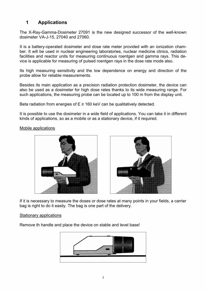
1 Applications The X-Ray-Gamma-Dosimeter 27091 is the new designed successor of the well-known dosimeter VA-J-15, 27040 and 27060. It is a battery-operated dosimeter and dose rate meter provided with an ionization cham-ber. It will be used in nuclear engineering laboratories, nuclear medicine clinics, radiation facilities and reactor units for measuring continuous roentgen and gamma rays. This de-vice is applicable for measuring of pulsed roentgen rays in the dose rate mode also. Its high measuring sensitivity and the low dependence on energy and direction of the probe allow for reliable measurements. Besides its main application as a precision radiation protection dosimeter, the device can also be used as a dosimeter for high dose rates thanks to its wide measuring range. For such applications, the measuring probe can be located up to 100 m from the display unit. Beta radiation from energies of E ≥ 160 keV can be qualitatively detected. It is possible to use the dosimeter in a wide field of applications. You can take it in different kinds of applications, so as a mobile or as a stationary device, if it required. Mobile applications
If it is necessary to measure the doses or dose rates at many points in your fields, a carrier bag is right to do it easily. The bag is one part of the delivery. Stationary applications Remove th handle and place the device on stable and level base!
4
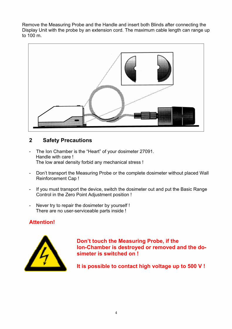
Remove the Measuring Probe and the Handle and insert both Blinds after connecting the Display Unit with the probe by an extension cord. The maximum cable length can range up to 100 m.
2 Safety Precautions - The Ion Chamber is the “Heart” of your dosimeter 27091. Handle with care ! The low areal density forbid any mechanical stress ! - Don’t transport the Measuring Probe or the complete dosimeter without placed Wall
Reinforcement Cap ! - If you must transport the device, switch the dosimeter out and put the Basic Range
Control in the Zero Point Adjustment position !
- Never try to repair the dosimeter by yourself ! There are no user-serviceable parts inside ! Attention!
Don’t touch the Measuring Probe, if the Ion-Chamber is destroyed or removed and the do-simeter is switched on ! It is possible to contact high voltage up to 500 V !
5
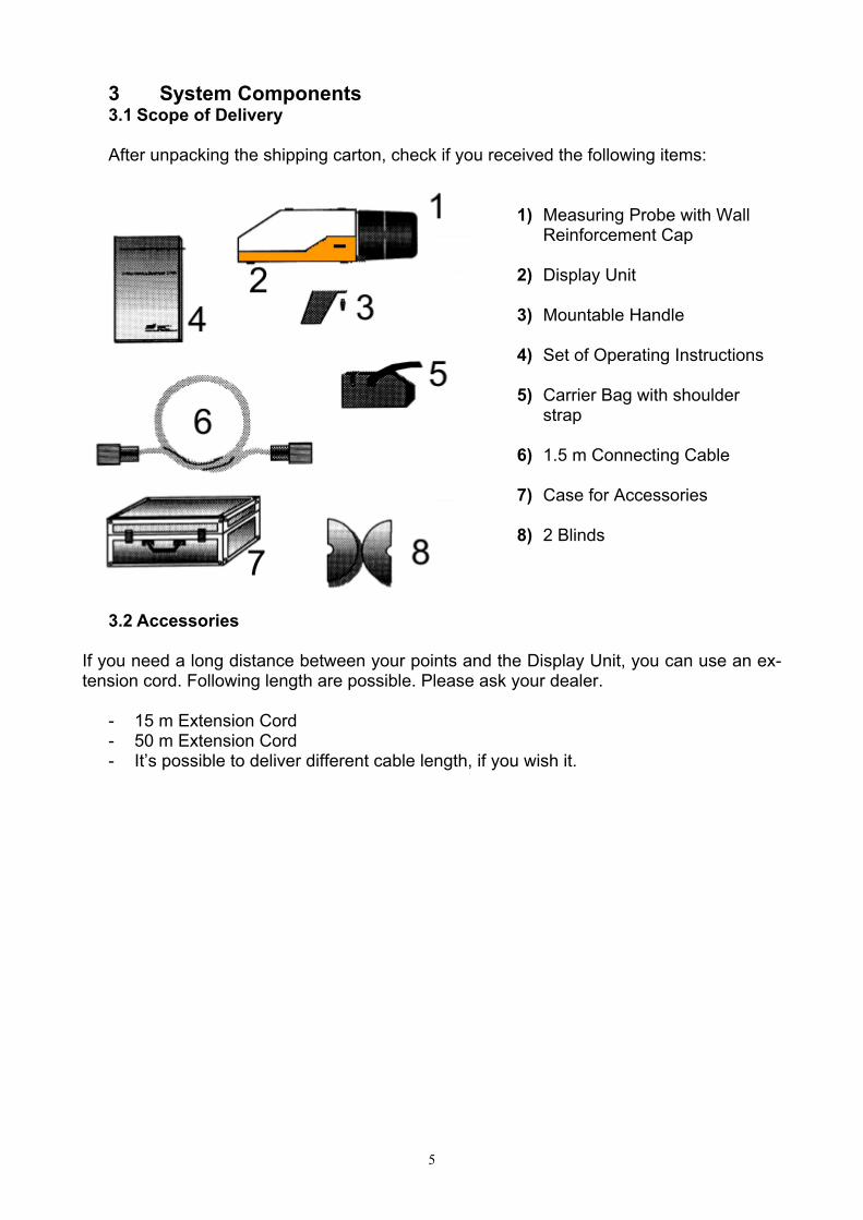
3 System Components 3.1 Scope of Delivery After unpacking the shipping carton, check if you received the following items:
1) Measuring Probe with Wall
Reinforcement Cap 2) Display Unit 3) Mountable Handle 4) Set of Operating Instructions 5) Carrier Bag with shoulder
strap 6) 1.5 m Connecting Cable 7) Case for Accessories 8) 2 Blinds
3.2 Accessories
If you need a long distance between your points and the Display Unit, you can use an ex-tension cord. Following length are possible. Please ask your dealer.
- 15 m Extension Cord - 50 m Extension Cord - It’s possible to deliver different cable length, if you wish it.

6
4 Using Guide 4.1 Preparing and Battery Changing
The dosimeter is delivered without batteries. You must insert 4 round cells into the device before starting the first measurement. Loading the batteries 1. Unpack the device out of the transport case 2. Put the dosimeter with upper side Down on a stable and level base.
3. Push the bottoms at right and left side into the case and pull-up this part.
4. Place the parts after another.
5. Unscrew the Measuring Probe.
6. Insert the batteries, aligning there Polarities as indicated inside at the Nickel coated clamps.

7
7. Slide the first cell to the front side and push the next into the clamp.
8. Repeat this at the next side.
9. Place the mechanical connection at the Basic Range Control of the probe correctly. Screw the Measuring Probe at the connector.
10. Insert the part into the part beginning with the backside snapper.
11. Push both parts together careful.

8
Battery Changing Do the same like the first preparing, but remove the cells by doing the step 6 in the reverse order. Attention!
- Load new batteries with there aligned polarities correctly ! - When the dosimeter is not in use for long time, remove the bat-
teries and store them in dry and cool room ! - Remove spent batteries immediately ! - Protect the Enviroment !
Do not discard used batteries with your household rubbish !
4.2 Outlook and Functions of operational Controls, Display and Connectors
1. Measuring Probe with Wall Reinforcement Capp Remove the cap: - Turn to right - Pull to the front side 2. Display Unit Part 1 (Upper part) 3. Display Unit Part 2 (Under part) 4. Handle with Toogle Fastening Remove the Handle: - Turn the toogle to right - Pull up the toogle 5. BNC-Jack for recorder connection

9
6. LCD Screen Selected Alert Level Digital Read Out Selected Basic Range Selected Final Value Horn Symbol (Blinking, if the measured level is higher as the se-lected threshold) Quasi Analogue Bar Chart Battery Symbol indicated Undervoltage
7. Front Panel of the Display Unit Part 1 (Upper part) Basic Range Control
Piezo Buzzer
10
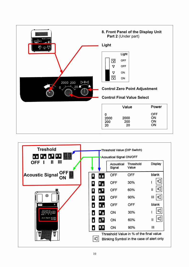
8. Front Panel of the Display Unit Part 2 (Under part) Light
Control Zero Point Adjustment Control Final Value Select

11
10. Measuring Probe Round Connector Basic Range Control
4.3 Check of Display, Battery Voltage and electrical Zero Adjustment
Display Check: 1. Switch the device ON by the control: Final Value Select Position : 2000
2. All Segments of the LCD will be active for few seconds.
3. Compare the read out with the picture Above.
12
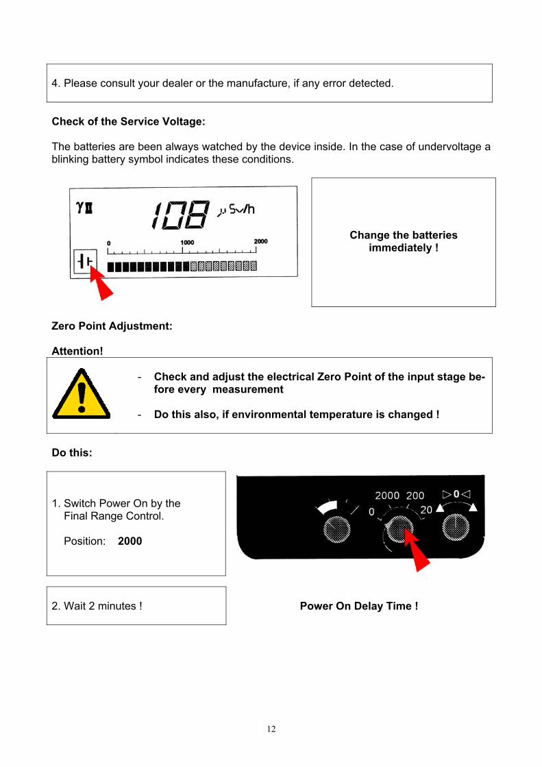
4. Please consult your dealer or the manufacture, if any error detected. Check of the Service Voltage: The batteries are been always watched by the device inside. In the case of undervoltage a blinking battery symbol indicates these conditions.
Change the batteries immediately !
Zero Point Adjustment: Attention!
- Check and adjust the electrical Zero Point of the input stage be-
fore every measurement - Do this also, if environmental temperature is changed !
Do this: 1. Switch Power On by the Final Range Control. Position: 2000
2. Wait 2 minutes !
Power On Delay Time !
13
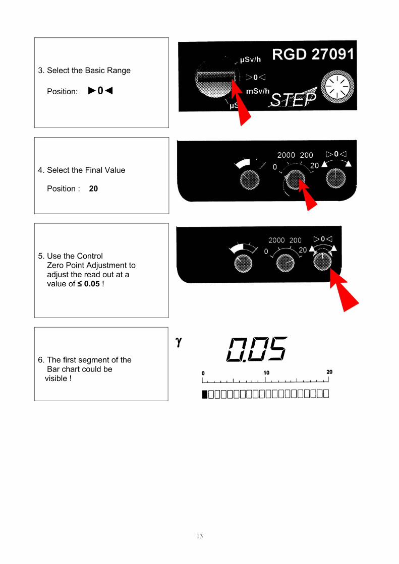
3. Select the Basic Range Position: ►0◄
4. Select the Final Value Position : 20
5. Use the Control Zero Point Adjustment to adjust the read out at a value of ≤ 0.05 !
6. The first segment of the Bar chart could be visible !
14
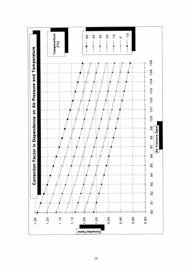
4.4 Correction of Measurements
The dosimeter is calibrated at Refernece Conditions (see Technical Data) by the manufac-ture. Perhaps, the physical data of the ion chamber dependence on air pressure and tem-perature. Correct the dependence on Air Pressure p and Temperature ϑ use therefore the following equation or the diagram in the appendix.
fKK ∗=0
][29333,101])[273(
kPapCf
∗∗°+
=ϑ
If the Photon Energy of radiation is known approximately, it is possible to reduce the error of energy dependence by calculation. Use therefore the diagram in the appendix to get the Sensitive on Energy q/q0 of the dosimeter and calculate:
qqVVenergy 0*=
V: Read out without correction These methods reduced the Additional Error.
Energy Range
Reduced Additional Error
6 keV – 15 keV 15 keV – 2 MeV
± 10 % ±5 %
4.5 Adjustment of Alert Levels
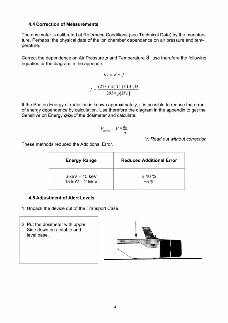
1. Unpack the device out of the Transport Case.
2. Put the dosimeter with upper Side down on a stable and level base.
15
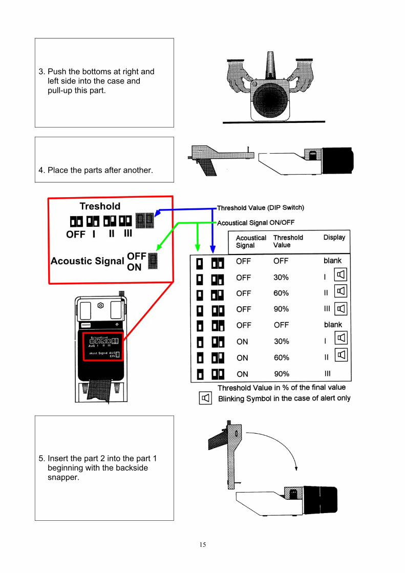
3. Push the bottoms at right and left side into the case and pull-up this part.
4. Place the parts after another.
5. Insert the part 2 into the part 1 beginning with the backside snapper.

16
6. Push both parts together careful.
4.6 Measuring Range Selection
The wide measuring range of the dosimeter is split in 3 Basic Ranges and each of them is also split in 3 linear fields.
Attention!
- Always atart with the most insensitivity Final Value (2000) ! - If you change the Basic Range, select the Final Value 2000 also
before !
17
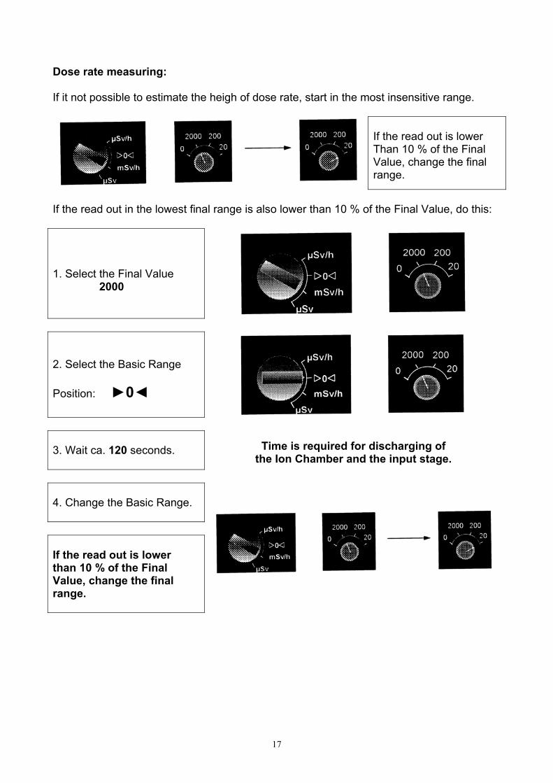
Dose rate measuring: If it not possible to estimate the heigh of dose rate, start in the most insensitive range.
If the read out is lower Than 10 % of the Final Value, change the final range.
If the read out in the lowest final range is also lower than 10 % of the Final Value, do this: 1. Select the Final Value 2000
2. Select the Basic Range Position: ►0◄ 3. Wait ca. 120 seconds.
Time is required for discharging of
the Ion Chamber and the input stage. 4. Change the Basic Range. If the read out is lower than 10 % of the Final Value, change the final range.

18
Dose measuring: 1. Select the Basic Range Position: ►0◄
2. Select the Final Value 2000
3. Change Basic Range for a short time into Position: mSv/h
Time is required for discharging of the
Integration capacitor of the Input stage.
4. Change the Basic Range Into position: µSv The measuring period starts In this moment.
If the read out is lower than 10 % of the Final Value at the end of your measuring period, change the final range.
The new measuring period starts after repeating the change of the Basic Range into Posi-tion µSv.

19
Note:
- For high exactness watch the read out in a period of 1 minute and calculate the average:
2)( maxmin VVK +
=
- In the most sensitivity range of dose and dose rate it is possible to correct the
influence of leakage currents of the probe by following calculation:
Dose: Read Out – 0.01 µSv / min Dose Rate: Read Out – 0.6 µSv / h
- If the environmental conditions had been changed by transport, wait about 2
hours. In this time the temperature inside of the probe will adapt to the envi-ronmental temperature.
4.7 Usage of the Wall Reinforcement Cap
The large Energy Range of the Dosimeter required the placement or the displacement of the Wall Reinforcement Cap in dependence on the kind of radiation; X-Rays, gamma ra-diation or Bremsstrahlung.
Radiation
Energy
Wall Reinforcement
Cap
Note
x-rays, γ
x-rays, γ
x-rays, γ
β
6 – 100 keV
20 keV – 3 MeV
> 3 MeV
≥ 160 keV
NO Yes Yes + 2 cm thick PMMA plate NO
Direction of radiation must be vertical to surface of the Meas-uring Probe Qualitatively only
Do this:
20
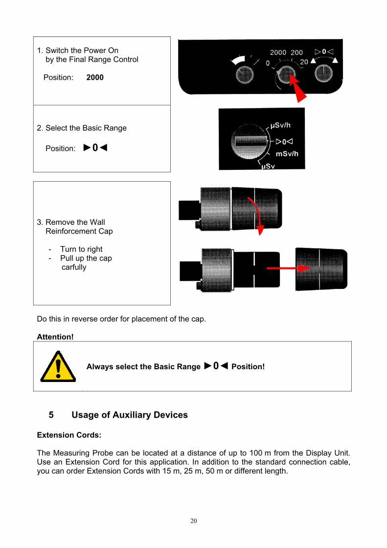
1. Switch the Power On by the Final Range Control Position: 2000
2. Select the Basic Range Position: ►0◄
3. Remove the Wall Reinforcement Cap
- Turn to right - Pull up the cap carfully
Do this in reverse order for placement of the cap. Attention!
Always select the Basic Range ►0◄ Position!
5 Usage of Auxiliary Devices
Extension Cords: The Measuring Probe can be located at a distance of up to 100 m from the Display Unit. Use an Extension Cord for this application. In addition to the standard connection cable, you can order Extension Cords with 15 m, 25 m, 50 m or different length.

21
Attention!
Do always: Switch the Power out, if you start to remove the Measuring Probe! Adjust the electrical Zero Point again, if you had connected the cable between Display Unit and the Probe. Correct the dependence on temperature and air pressure by calcula-tion.
Note: Only the standard connecting cable with a length of 1.5 m is a part of the delivery. Commercial Tripods The Measuring Probe is provided with a 3/8” thread. Thus can be used for fastern custom-ary by trade tripod. Use a connecting piece fore this operation perhaps.
6 Service and Maintenance
6.1 General Precautions
The Device RGD 27091 and 27091-U is a precision radiation protection dosimeter. For this application it is liable for gauging. There is prohibited to open the device. The Dosimeter is sealed. The user had only to do:
- Battery Changing - Cleaning - Function Check every 6 month
6.2 Decontamination It is necessary to clean the Display Unit, the Measuring Probe and the removed Wall Rein-forcement Cap, if the device radioactive contaminated. You should use a cloth, wetted by soap suds for this. The cleaning of the Ion Chamber could not be successfully. The low areal density and the kind of surface is not enough resist to remove the contamination completely. Foe expect-ing contamination, use an effective protection for the Ion chamber, e.g. polyethylene bag or foil.
22
Attention!
- Don’t use solvents, e.g. petrol, benzene or acetone for cleaning!- In this case, you will damage the dosimeter!
6.3 Drying of the Measuring Probe If you transport the dosimeter from a location with temperature at the lowest limit to loca-tion with higher temperature and high air humidity, water will condensed at the device. This is a possible reason for increasing of leakage currents. The error in this case can reach up to > 1.0 µSv/h. Wait until the device is dry before starting any measurements. Use a heating compartment or an air blower to speed up the process, but the temperature must be lower then 50 °C! Remove the Wall Reinforcement Cap before. Attention!
Don’t touch the Measuring Probe, if the Ion Chamber is destroyed or removed and the dosimeter is switched ON! It is possible to contact high voltage up to 500 V!
Never try to repair the dosimeter by yourself! There are no user-serviceable parts inside!
7 Storage Conditions - Storage temperature range -25 °C to +55 °C - Outside air pressure 800 hPa to 1100 hPa - Relative air humidity ≤ 80 % - when the dosimeter is not in use for long time, remove the batteries and store them in dry and cool room! - Pack the dosimeter into the Transport Case before storage them! - The storage room must be cool and dry, free of aggressive chemical or solvent vapors!
23
8 Transport Conditions
- The Ion Chamber is the “Heart” of your dosimeter 27091. Handle with care ! The low areal density forbid any mechanical stress ! - Don’t transport the Measuring Probe or the complete dosimeter without placed Wall
Reinforcement Cap ! - If you must transport the device, switch the dosimeter out and put the Basic Range
Control in the Zero Point Adjustment position ! Temperature range -25 °C to +55 °C Outside air pressure 800 hPa to 1100 hPa Relative air humidity ≤ 80 %
9 Technical specification Units Photon equivalent dose Photon equivalent dose rate Read Out - Dose µSv in 3 linear fields final values: 20, 200 and 2000 - Dose Rate basic range µSv/h in 3 linear fields final values: 20, 200 and 2000 basic range mSv/h in 3 linear fields final values: 20, 200 and 2000 Measuring Ranges
- In the final range 20 µSv/h, the measuring range starts at 3 µSv/h - In all other indicating ranges, the measuring range starts at 10 % of the final value
Thresholds values/ disabled or adjustable at 30 %, 60 % or 90 % Alert levels of the final value - acoustic Signal Piezzo-buzzer - optical Signal Horn-symbol on LCD-Screen Both are independent ON/OFF switchable Energy ranges - without wall reinforcement cap 6 keV to 100 keV - with wall reinforcement cap 20 keV to 3 Mev

24
(7.5 MeV with additional PMMA shielding) Radiation Detector air equivalent ionization chamber - volume 600 cm³ - areal density 35 mg/cm² Wall reinforcement cap removable - areal density 500 mg/cm² Refernce point Centre of the ion-chamber at a distance of 6 cm from the front side Overload resistance ≤ 100 Sv/h in all ranges Reference Conditions - temperature 20 °C - air pressure 101,3 kPa - photon energy 662 keV (Cs-137) - radiation direction radial - distance between the radiation ≥ 0,8 m source and the refernce point of ion chamber - correction of air pressure done Gauging error max. ± 15 % under reference condition in all rages Additional error - in depence on energy 6 keV to 15 keV -40 % 15 keV to 2 MeV ±10 % 2 MeV to 7.5 MeV ±30 % - directional dependence of ±45° ±5 % relative measuring sensitivity ±90° ±10 % - dependence on temperature ±3 % / 10 K (constant air pressure) - saturation deficit at 2000 mSv/h -5 % - error by leakage current +1 µSv/h - zero point error cancelled after zero point adjustment
25
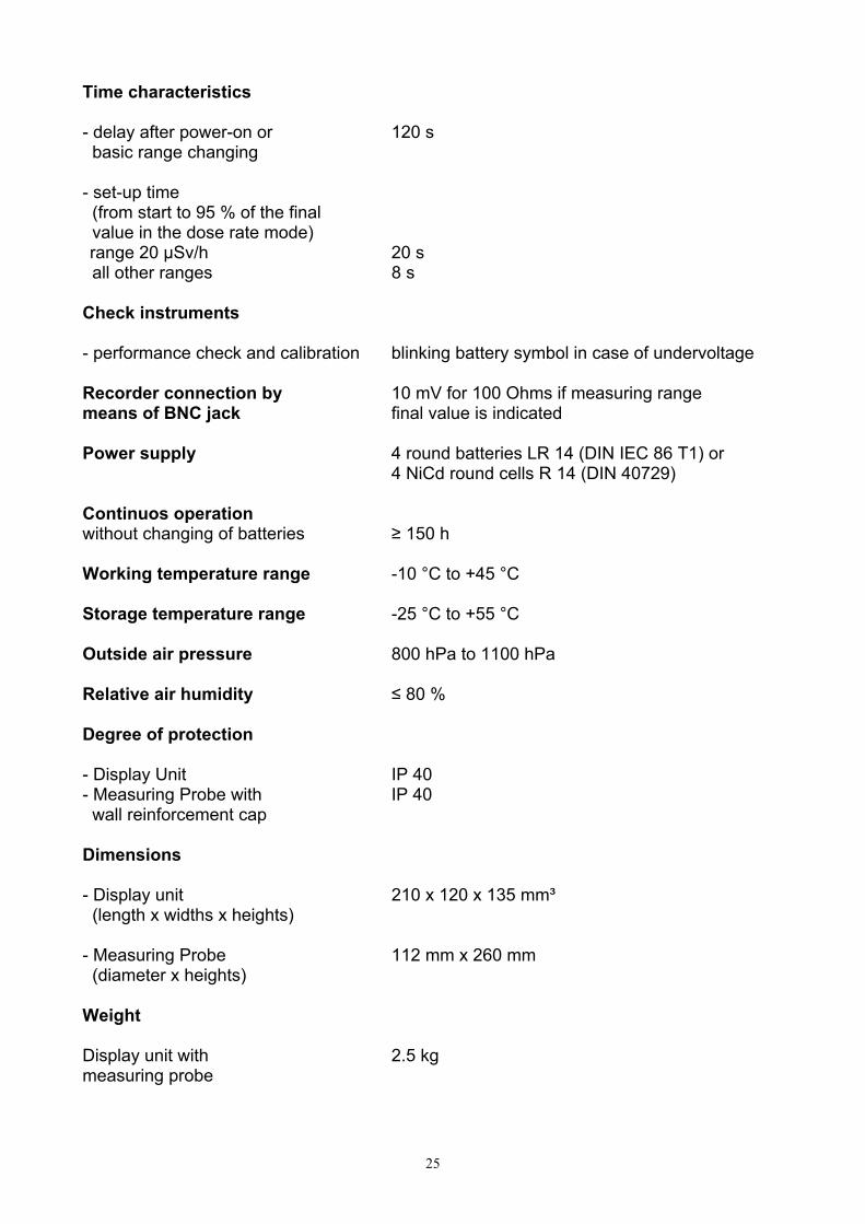
Time characteristics - delay after power-on or 120 s basic range changing - set-up time (from start to 95 % of the final value in the dose rate mode) range 20 µSv/h 20 s all other ranges 8 s Check instruments - performance check and calibration blinking battery symbol in case of undervoltage Recorder connection by 10 mV for 100 Ohms if measuring range means of BNC jack final value is indicated Power supply 4 round batteries LR 14 (DIN IEC 86 T1) or 4 NiCd round cells R 14 (DIN 40729) Continuos operation without changing of batteries ≥ 150 h Working temperature range -10 °C to +45 °C Storage temperature range -25 °C to +55 °C Outside air pressure 800 hPa to 1100 hPa Relative air humidity ≤ 80 % Degree of protection - Display Unit IP 40 - Measuring Probe with IP 40 wall reinforcement cap Dimensions - Display unit 210 x 120 x 135 mm³ (length x widths x heights) - Measuring Probe 112 mm x 260 mm (diameter x heights) Weight Display unit with 2.5 kg measuring probe

26
Mechanical stability - test conditions DIN IEC 68 part 2-6 (10-500) Hz, 0.15 mm, 2 g DIN IEC 68 part 2-29 peak acceleration: 150 m/s² shock period: 6 ms shock counts: 500
10 Internal Structure A given radiation field, with a photon equivalent dose rate HX generate a current IC in the ion chamber. The volume of the ion-chamber is V. The factor ρ represents the actually air density in dependence on air pressure and temperature. The value of IK is the result of the following equation in the case of saturation:
XC HVKI ***1 ρ= K1 … proportional factor
The voltage at the chamber UC is high enough to minimize the recombination of charges in the volume of the chamber.
The current IC flow into the inverting input of the amplifier A. All basic ranges are controlled by the switch S1. The final value is selected by R2. The output voltage of the amplifier is
CA IRA
U *1*1−=
in the dose rate mode and
∫−= dtICA
U CA ***1
in the dose mode.
27
The variable A is a result of a factor K2 multiplied with the final value of the selected range.
FKA *2= where: F = 2000, 200 or 20 (final value)
The analogue to digital converter ADC converts the voltage UADC to proportional digital value. This value is shown as a digital value and as a quasi analogue bar chart at the LCD. The potentiometer R4 “Correction” will be used to compensate influences of air pressure and temperature. The offset-voltage of the input stage of the amplifier A are adjusted by the control “zero point adjustment”. The switches S3 and S4 allow to set or reset the optical and the acoustic alert levels. All supply voltages are generated by a transverter. Appendix Diagramm 1: “Correction Factor in Dependence on Air Pressure and Temperature” Diagramm 2: “Dependence on Energy of RGD 27091”
28

29