roland user manual for the camm-1 pro: pnc-1860, pnc-1410...
TRANSCRIPT
USER'S MANUAL
* This User's Manual is intended for the PNC-1860, PNC-1410, as well as PNC-1210.
PNC-1860PNC-1860PNC-1860PNC-1860PNC-1860PNC-1410PNC-1410PNC-1410PNC-1410PNC-1410PNC-12 10PNC-12 10PNC-12 10PNC-12 10PNC-12 10

NOTICEGrounding Instructions
Do not modify the plug provided - if it will not fit the outlet,have the proper outlet installed by a qualified electrician.
Check with qualified electrician or service personnel if thegrounding instructions are not completely understood, or if indoubt as to whether the tool is properly grounded.
Use only 3-wire extension cords that have 3-pronggrounding plugs and 3-pole receptacles that accept the tool’splug.
Repair or replace damaged or worn out cord immediately.
Operating Instructions
KEEP WORK AREA CLEAN. Cluttered areas and benchesinvites accidents.
DON’T USE IN DANGEROUS ENVIRONMENT. Don’tuse power tools in damp or wet locations, or expose them torain. Keep work area well lighted.
DISCONNECT TOOLS before servicing; when changingaccessories, such as blades, bits, cutters, and like.
REDUCE THE RISK OF UNINTENTIONAL STARTING.Make sure the switch is in off position before plugging in.
USE RECOMMENDED ACCESSORIES. Consult theowner’s manual for recommended accessories. The use ofimproper accessories may cause risk of injury to persons.
NEVER LEAVE TOOL RUNNING UNATTENDED.TURN POWER OFF. Don’t leave tool until it comes to acomplete stop.
For the USA
FEDERAL COMMUNICATIONS COMMISSIONRADIO FREQUENCY INTERFERENCE
STATEMENT
This equipment has been tested and found to comply with thelimits for a Class B digital device, pursuant to Part 15 of theFCC Rules.These limits are designed to provide reasonable protectionagainst harmful interference in a residential installation.This equipment generates, uses, and can radiate radiofrequency energy and, if not installed and used in accordancewith the instructions, may cause harmful interference to radiocommunications.However, there is no guarantee that interference will notoccur in a particular installation.If this equipment does cause harmful interference to radio ortelevision reception, which can be determined by turning theequipment off and on, the user is encouraged to try to correctthe interference by one or more of the following measures:- Reorient or relocate the receiving antenna.- Increase the separation between the equipment and
receiver.- Connect the equipment into an outlet on a circuit different
from that to which the receiver is connected.- Consult the dealer or an experienced radio/TV technician
for help.
Unauthorized changes or modification to this system can voidthe users authority to operate this equipment.
The I/O cables between this equipment and the computingdevice must be shielded.
For Canada
CLASS B NOTICE
This Class B digital apparatus meets all requirements of theCanadian Interference-Causing Equipment Regulations.
CLASSE B AVIS
Cet appareil numérique de la classe B respecte toutes lesexigences du Règlement sur le matériel brouilleur duCanada.
ROLAND DG CORPORATION1-6-4 Shinmiyakoda, Hamamatsu-shi, Shizuoka-ken, JAPAN 431-2103MODEL NAME : See the MODEL given on the rating plate.RELEVANT DIRECTIVE : EC MACHINERY DIRECTIVE (89/392/EEC)
EC LOW VOLTAGE DIRECTIVE (73/23/EEC)EC ELECTROMAGNETIC COMPATIBILITY DIRECTIVE (89/336/EEC)
WARNINGThis is a Class A product. In a domestic environment this product may cause radio interference in whichcase the user may be required to take adequate measures.

Typographic Conventions .......................................................................................................................................i
To Ensure Safe Use ............................................................................................................................ii
About the Labels Affixed to the Unit ................................................................................iii
To Ensure Correct Use ..............................................................................................................................................iv1 CHECKING ACCESSORIES ............................................................................................................................. 12 PART NAMES AND FUNCTIONS ..................................................................................................................... 1
2-1 Front View .............................................................................................................................................. 12-2 Rear View ............................................................................................................................................... 12-3 Operation Panel ..................................................................................................................................... 2
3 BASIC OPERATION .......................................................................................................................................... 33-1 Setting Up and Connection .................................................................................................................... 33-2 Installing the Cutter ................................................................................................................................ 43-3 Loading the Material ............................................................................................................................... 5
Loading Roll Material .............................................................................................................................. 6Loading Flat Material (Standard-size Material, Cut Material, Etc.) ......................................................... 8To Perform Long Cutting ...................................................................................................................... 10
3-4 Selecting the Interface .......................................................................................................................... 113-5 Cutting Test - Setting Cutting Speed, Blade Force, and Blade Compensation .................................... 123-6 Downloading Cutting Data .................................................................................................................... 133-7 Applying the Completed Cutout ............................................................................................................ 153-8 When Completed Cutting ..................................................................................................................... 15
4 CARE AND MAINTENANCE ........................................................................................................................... 165 ABOUT THE CUTTING AREA ........................................................................................................................ 176 USING THE DISPLAY MENUS ....................................................................................................................... 177 DISPLAY MENUS FLOWCHART .................................................................................................................... 188 DISPLAY MENU LISTS ................................................................................................................................... 209 BLADES AND MATERIALS............................................................................................................................. 2410 PLOTTING ON PAPER MEDIA ....................................................................................................................... 2511 WHAT TO DO IF .............................................................................................................................................. 2612 SUPPORTED INSTRUCTION SETS .............................................................................................................. 2913 CHARACTER SET .......................................................................................................................................... 30SPECIFICATIONS ..................................................................................................................................................... 31
CONTENTS
Thank you very much for purchasing the CAMM-1 PNC-1860/1410/1210.
• To ensure correct and safe usage with a full understanding of this product's performance, please be sure to read through thismanual completely and store it in a safe location.
• Unauthorized copying or transferal, in whole or in part, of this manual is prohibited. • The contents of this operation manual and the specifications of this product are subject to change without notice. • The operation manual and the product have been prepared and tested as much as possible. If you find any misprint or error,
please inform us.

i
Typographic ConventionsThis manual uses certain typographic symbols, outlined below.
This indicates a point requiring particular care to ensure safe use of the product.
: Failure to heed this message will result in serious injury or death.
: Failure to heed this message may result in serious injury or death.
: Failure to heed this message may result in minor injury.
: Indicates important information to prevent machine breakdown ormalfunction and ensure correct use.
: Indicates a handy tip or advice regarding use.
Copyright © 1995 ROLAND DG CORPORATION
Windows is registered trademark or trademark of Microsoft Corporation in the United States and/or other countries.
ii
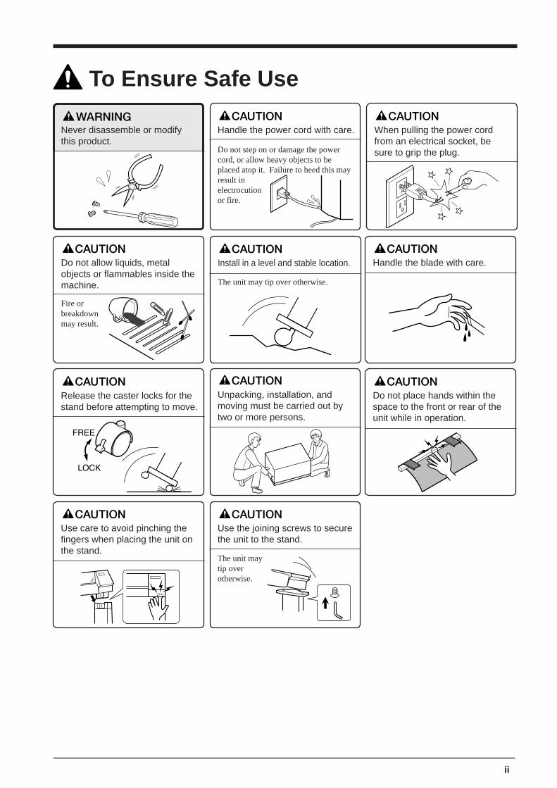
To Ensure Safe Use
Never disassemble or modifythis product.
Do not allow liquids, metalobjects or flammables inside themachine.
Fire orbreakdownmay result.
Do not step on or damage the powercord, or allow heavy objects to beplaced atop it. Failure to heed this mayresult inelectrocutionor fire.
Handle the power cord with care. When pulling the power cordfrom an electrical socket, besure to grip the plug.
The unit may tip over otherwise.
Install in a level and stable location.
Release the caster locks for thestand before attempting to move.
Unpacking, installation, andmoving must be carried out bytwo or more persons.
Use the joining screws to securethe unit to the stand.
The unit maytip overotherwise.
Use care to avoid pinching thefingers when placing the unit onthe stand.
Do not place hands within thespace to the front or rear of theunit while in operation.
Handle the blade with care.

Rating label
iii
Do not allow the hands within thespace to the front or rear of the unitwhile in operation.
About the Labels Affixed to the UnitThese labels are affixed to the body of this product. The following figure describes the location and content ofthese messages.
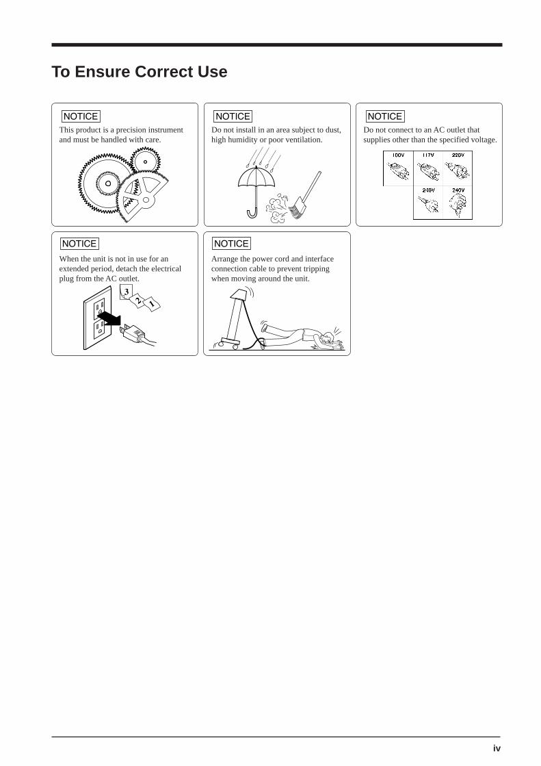
To Ensure Correct Use
This product is a precision instrumentand must be handled with care.
Do not install in an area subject to dust,high humidity or poor ventilation.
Do not connect to an AC outlet thatsupplies other than the specified voltage.
When the unit is not in use for anextended period, detach the electricalplug from the AC outlet.
Arrange the power cord and interfaceconnection cable to prevent trippingwhen moving around the unit.
iv

v
MEMO
1
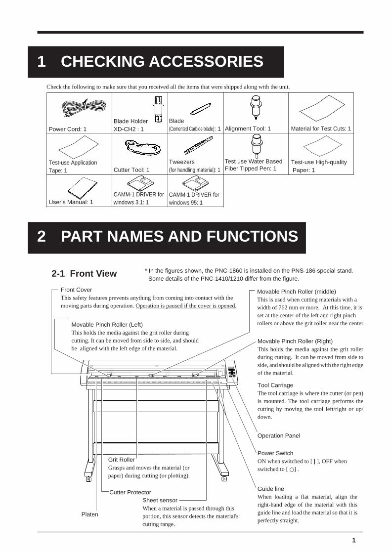
Check the following to make sure that you received all the items that were shipped along with the unit.
Blade HolderXD-CH2 : 1Power Cord: 1
Blade(Cemented Carbide blade): 1 Alignment Tool: 1 Material for Test Cuts: 1
Test-use ApplicationTape: 1 Cutter Tool: 1
Tweezers(for handling material): 1
Test use Water BasedFiber Tipped Pen: 1
Test-use High-quality Paper: 1
1 CHECKING ACCESSORIES
2-1 Front View
Front CoverThis safety features prevents anything from coming into contact with themoving parts during operation. Operation is paused if the cover is opened.
* In the figures shown, the PNC-1860 is installed on the PNS-186 special stand.Some details of the PNC-1410/1210 differ from the figure.
2 PART NAMES AND FUNCTIONS
Cutter Protector
Movable Pinch Roller (Left)This holds the media against the grit roller duringcutting. It can be moved from side to side, and shouldbe aligned with the left edge of the material.
Movable Pinch Roller (middle)This is used when cutting materials with awidth of 762 mm or more. At this time, it isset at the center of the left and right pinchrollers or above the grit roller near the center.
Movable Pinch Roller (Right)This holds the media against the grit rollerduring cutting. It can be moved from side toside, and should be aligned with the right edgeof the material.
Tool CarriageThe tool carriage is where the cutter (or pen)is mounted. The tool carriage performs thecutting by moving the tool left/right or up/down.
Power SwitchON when switched to [ ], OFF whenswitched to [ ] .
Guide lineWhen loading a flat material, align theright-hand edge of the material with thisguide line and load the material so that it isperfectly straight.
Operation Panel
Grit RollerGrasps and moves the material (orpaper) during cutting (or plotting).
Platen
User’s Manual: 1
Sheet sensorWhen a material is passed through thisportion, this sensor detects the material'scutting range.
CAMM-1 DRIVER forwindows 3.1: 1
CAMM-1 DRIVER forwindows 95: 1

2
1 cut 50Cm/s0.250mm 30gf
DisplayProvides menu display, configurationpreferences, coordinates, as well aserror messages for troubleshooting.
2-3 Operation Panel
MENU Key MENU
Employed to select among theavailable menus, or to cancel themaking of a setting at a particularmenu.
Cursor Keys Used to move the blinking cursor. The
and keys are also used tomove the material, and the and keys are used to move the toolcarriage.
ENTER Key ENTER
Press to enter into a subroutine of theitem selected using the cursor keys orto confirm (save) the value set inconfiguration.
TEST Key TEST
Pressed to execute a cutting test (Useto confirm material specifications aswell as cutting speed, blade force, andblade compensation).
SETUP Key SETUP
Pressing this key after loading a material causes thematerial's cutting range to be determined automatically.
Blinking CursorUsed to select the desired item from the menu. The key moves itto the right, the key moves it to the left, the key moves it up,the key moves it down.
Power LEDThis lights up when the power isswitched on.
SETUP LEDThis lights up when the SETUP key ispressed to pause the PNC-1860/1410/1210.
2-2 Rear View
Sheet Loading LeverWhen loading media, lift this lever to lower topinch rollers. To removing media, lower thislever to raise the pinch roller.
Parallel (Centronics) ConnectorIn a parallel configuration, this connector is where youneed to connect the parallel cable in order to commu-nicate with your computer.
Serial (RS-232C) ConnectorIn a serial configuration, this connector iswhere you need to connect the serial cable thatis used to communicate with your computer.
Power Connector [AC IN]This jack accepts a standard AC power cord.
Sheet SensorWhen a material is passed through thisportion, this sensor detects the material'scutting range.
3
3 BASIC OPERATION* In this manual, sections that explain
commons points for the PNC-1860/1410/1210 use only illustrations of thePNC-1860. Some details of the PNC-1410/1210 differ from the figure.
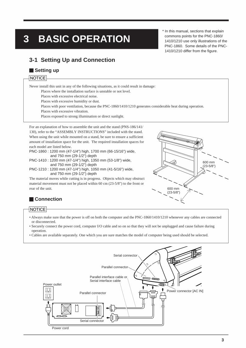
3-1 Setting Up and Connection
Setting up
Power outlet
Power cord
Never install this unit in any of the following situations, as it could result in damage:Places where the installation surface is unstable or not level.Places with excessive electrical noise.Places with excessive humidity or dust.Places with poor ventilation, because the PNC-1860/1410/1210 generates considerable heat during operation.Places with excessive vibration.Places exposed to strong illumination or direct sunlight.
Connection
• Always make sure that the power is off on both the computer and the PNC-1860/1410/1210 whenever any cables are connectedor disconnected.
• Securely connect the power cord, computer I/O cable and so on so that they will not be unplugged and cause failure duringoperation.
• Cables are available separately. One which you are sure matches the model of computer being used should be selected.
Serial connector
Parallel connector
Serial connector
Parallel connector
Parallel interface cable orSerial interface cable
Power connector [AC IN]
For an explanation of how to assemble the unit and the stand (PNS-186/141/130), refer to the “ASSEMBLY INSTRUCTIONS” included with the stand.When using the unit while mounted on a stand, be sure to ensure a sufficientamount of installation space for the unit. The required installation spaces foreach model are listed below.PNC-1860 : 1200 mm (47-1/4") high, 1700 mm (66-15/16") wide,
and 750 mm (29-1/2") depthPNC-1410 : 1200 mm (47-1/4") high, 1350 mm (53-1/8") wide,
and 750 mm (29-1/2") depthPNC-1210 : 1200 mm (47-1/4") high, 1050 mm (41-5/16") wide,
and 750 mm (29-1/2") depthThe material moves while cutting is in progress. Objects which may obstructmaterial movement must not be placed within 60 cm (23-5/8") to the front orrear of the unit.
600 mm(23-5/8")
600 mm(23-5/8")
4
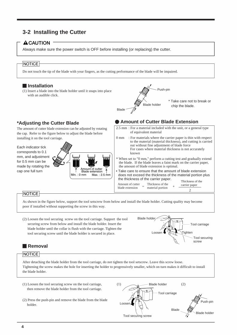
3-2 Installing the Cutter
Do not touch the tip of the blade with your fingers, as the cutting performance of the blade will be impaired.
Always make sure the power switch is OFF before installing (or replacing) the cutter.
Installation(1) Insert a blade into the blade holder until it snaps into place
with an audible click.
Blade
Blade holder* Take care not to break or
chip the blade.
Push-pin
*Adjusting the Cutter BladeThe amount of cutter blade extension can be adjusted by rotatingthe cap. Refer to the figure below to adjust the blade beforeinstalling it on the tool carriage.
Amount of Cutter Blade Extension
Each indicator tickcorresponds to 0.1mm, and adjustmentfor 0.5 mm can bemade by rotating thecap one full turn
Blade holder
Push-pin
Blade
Tool carriage
Loosen
Tool securing screw
Blade holder
After detaching the blade holder from the tool carriage, do not tighten the tool setscrew. Leave this screw loose.Tightening the screw makes the hole for inserting the holder to progressively smaller, which on turn makes it difficult to installthe blade holder.
Removal
As shown in the figure below, support the tool setscrew from below and install the blade holder. Cutting quality may becomepoor if installed without supporting the screw in this way.
Tool carriage
Tighten
Blade holder
Loosen
Tool securingscrew
(2) Loosen the tool securing screw on the tool carriage. Support the toolsecuring screw from below and install the blade holder. Insert theblade holder until the collar is flush with the carriage. Tighten thetool securing screw until the blade holder is secured in place.
2.5 mm : For a material included with the unit, or a general typeof equivalent material
0 mm : For materials where the carrier paper is thin with respectto the material (material thickness), and cutting is carriedout without fine adjustment of blade forceFor cases where material thickness is not accuratelyknown
* When set to "0 mm," perform a cutting test and gradually extendthe blade. If the blade leaves a faint mark on the carrier paper,the amount of blade extension is optimal.
Amount of cutterblade extension
Thickness of thematerial portion= +
Thickness of thecarrier paper
2
• Take care to ensure that the amount of blade extensiondoes not exceed the thickness of the material portion plusthe thickness of the carrier paper.
(2) Press the push-pin and remove the blade from the bladeholder.
(1) Loosen the tool securing screw on the tool carriage,then remove the blade holder from the tool carriage.
(1) (2)
5
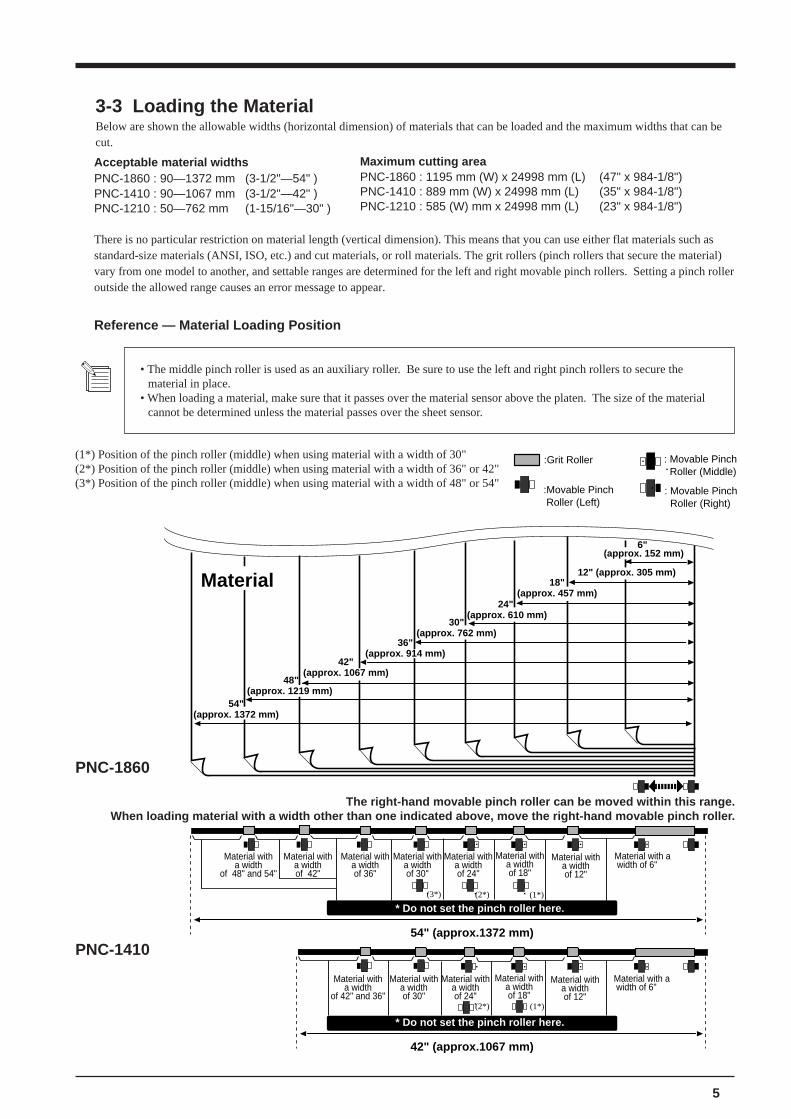
3-3 Loading the MaterialBelow are shown the allowable widths (horizontal dimension) of materials that can be loaded and the maximum widths that can becut.
Reference — Material Loading Position
Acceptable material widthsPNC-1860 : 90—1372 mm (3-1/2"—54" )PNC-1410 : 90—1067 mm (3-1/2"—42" )PNC-1210 : 50—762 mm (1-15/16"—30" )
Maximum cutting areaPNC-1860 : 1195 mm (W) x 24998 mm (L) (47" x 984-1/8")PNC-1410 : 889 mm (W) x 24998 mm (L) (35" x 984-1/8")PNC-1210 : 585 (W) mm x 24998 mm (L) (23" x 984-1/8")
There is no particular restriction on material length (vertical dimension). This means that you can use either flat materials such asstandard-size materials (ANSI, ISO, etc.) and cut materials, or roll materials. The grit rollers (pinch rollers that secure the material)vary from one model to another, and settable ranges are determined for the left and right movable pinch rollers. Setting a pinch rolleroutside the allowed range causes an error message to appear.
PNC-1410
• The middle pinch roller is used as an auxiliary roller. Be sure to use the left and right pinch rollers to secure thematerial in place.
• When loading a material, make sure that it passes over the material sensor above the platen. The size of the materialcannot be determined unless the material passes over the sheet sensor.
(1*) Position of the pinch roller (middle) when using material with a width of 30"(2*) Position of the pinch roller (middle) when using material with a width of 36" or 42"(3*) Position of the pinch roller (middle) when using material with a width of 48" or 54"
PNC-1860
The right-hand movable pinch roller can be moved within this range.When loading material with a width other than one indicated above, move the right-hand movable pinch roller.
:Movable Pinch Roller (Left)
: Movable Pinch Roller (Right)
: Movable Pinch Roller (Middle)
:Grit Roller
54" (approx.1372 mm)
Material with a width of 6"
* Do not set the pinch roller here.
42" (approx.1067 mm)
Material
(1*)(2*)
(1*)(2*)
(3*)
12" (approx. 305 mm)
24" (approx. 610 mm)
30"(approx. 762 mm)
36"(approx. 914 mm)
42"(approx. 1067 mm)
48"(approx. 1219 mm)
18"(approx. 457 mm)
54"(approx. 1372 mm)
6" (approx. 152 mm)
Material with a width
of 12"
Material with a width
of 18"
Material with a width
of 24"
Material with a width
of 30"
Material with a width of 6"
Material with a width
of 12"
Material with a width
of 18"
Material with a width
of 24"
Material with a width
of 30"
Material with a width
of 36"
Material with a width
of 42" and 36"
Material with a width of 42"
Material with a width
of 48" and 54"
* Do not set the pinch roller here.
6
Stopper
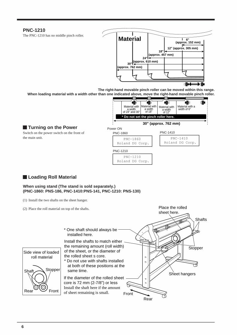
If the diameter of the rolled sheet core is 72 mm (2-7/8") or lessInstall the shaft here if the amount of sheet remaining is small.
Shafts
* One shaft should always be installed here.
Install the shafts to match either the remaining amount (roll width) of the sheet, or the diameter of the rolled sheet s core.* Do not use with shafts installed at both of these positions at the same time.
RearFront
Place the rolledsheet here.
Sheet hangers
Front
Shaft Stopper
Rear
Side view of loaded roll material
Loading Roll Material
When using stand (The stand is sold separately.)(PNC-1860: PNS-186, PNC-1410:PNS-141, PNC-1210: PNS-130)
(1) Install the two shafts on the sheet hanger.
(2) Place the roll material on top of the shafts.
PNC-1210The PNC-1210 has no middle pinch roller.
PNC-1860 Roland DG Corp.
PNC-1860Power ON
PNC-1410 Roland DG Corp.
PNC-1410
PNC-1210 Roland DG Corp.
PNC-1210
Turning on the PowerSwitch on the power switch on the front ofthe main unit.
The right-hand movable pinch roller can be moved within this range.When loading material with a width other than one indicated above, move the right-hand movable pinch roller.
30" (approx. 762 mm)
* Do not set the pinch roller here.
Material
Material with a width of 6"
Material with a width
of 12"
Material with a width
of 18"
Material with a width
of 24" and 30"
12" (approx. 305 mm)
24" (approx. 610 mm)
30"(approx. 762 mm)
18"(approx. 457 mm)
6" (approx. 152 mm)
7
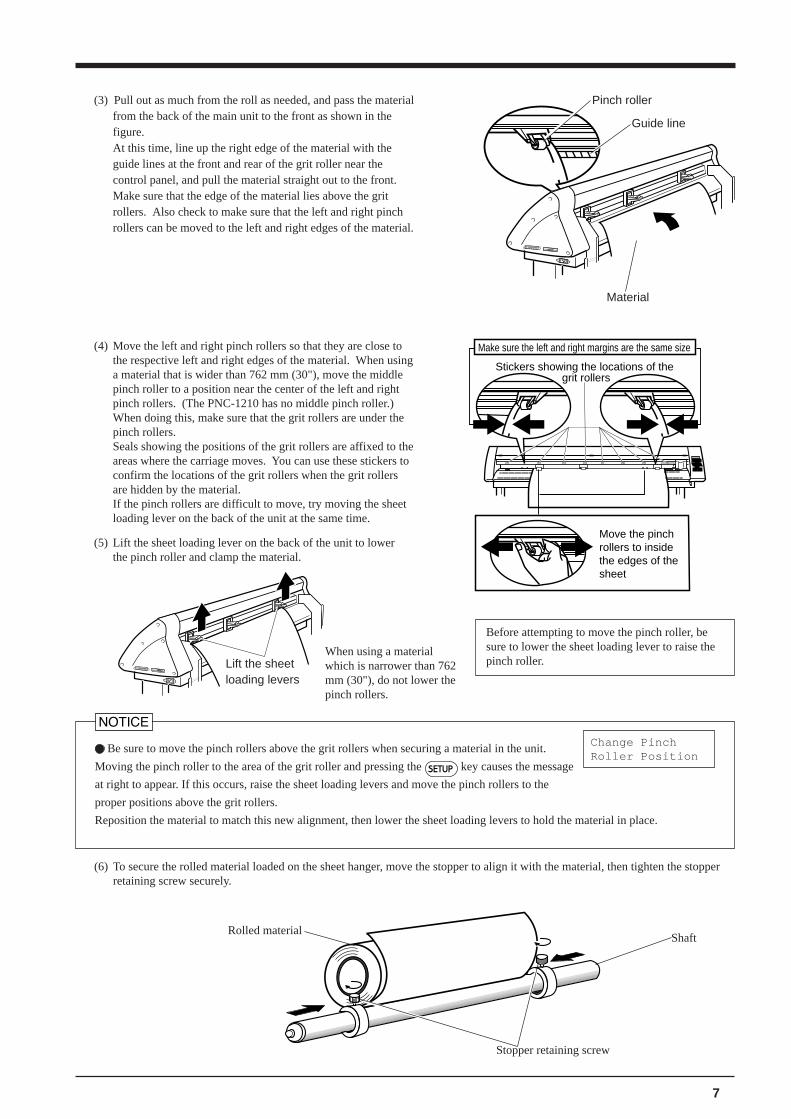
(3) Pull out as much from the roll as needed, and pass the materialfrom the back of the main unit to the front as shown in thefigure.At this time, line up the right edge of the material with theguide lines at the front and rear of the grit roller near thecontrol panel, and pull the material straight out to the front.Make sure that the edge of the material lies above the gritrollers. Also check to make sure that the left and right pinchrollers can be moved to the left and right edges of the material.
Guide line
Pinch roller
Material
Change PinchRoller Position
Be sure to move the pinch rollers above the grit rollers when securing a material in the unit.
Moving the pinch roller to the area of the grit roller and pressing the SETUP key causes the message
at right to appear. If this occurs, raise the sheet loading levers and move the pinch rollers to the
proper positions above the grit rollers.
Reposition the material to match this new alignment, then lower the sheet loading levers to hold the material in place.
When using a materialwhich is narrower than 762mm (30"), do not lower thepinch rollers.
Before attempting to move the pinch roller, besure to lower the sheet loading lever to raise thepinch roller.Lift the sheet
loading levers
Move the pinch rollers to inside the edges of the sheet
Stickers showing the locations of the grit rollers
Make sure the left and right margins are the same size(4) Move the left and right pinch rollers so that they are close tothe respective left and right edges of the material. When usinga material that is wider than 762 mm (30"), move the middlepinch roller to a position near the center of the left and rightpinch rollers. (The PNC-1210 has no middle pinch roller.)When doing this, make sure that the grit rollers are under thepinch rollers.Seals showing the positions of the grit rollers are affixed to theareas where the carriage moves. You can use these stickers toconfirm the locations of the grit rollers when the grit rollersare hidden by the material.If the pinch rollers are difficult to move, try moving the sheetloading lever on the back of the unit at the same time.
(5) Lift the sheet loading lever on the back of the unit to lowerthe pinch roller and clamp the material.
(6) To secure the rolled material loaded on the sheet hanger, move the stopper to align it with the material, then tighten the stopperretaining screw securely.
Rolled material
Stopper retaining screw
Shaft
8
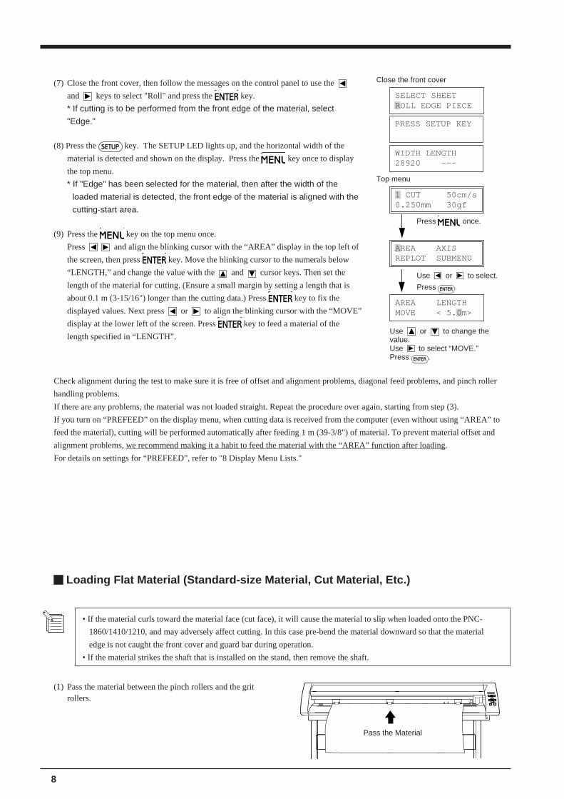
Pass the Material
Loading Flat Material (Standard-size Material, Cut Material, Etc.)
(1) Pass the material between the pinch rollers and the gritrollers.
AREA LENGTHMOVE < 5.0m>
Use or to change thevalue.Use to select “MOVE.”Press ENTER .
(7) Close the front cover, then follow the messages on the control panel to use the
and keys to select "Roll" and press the ENTER key.
* If cutting is to be performed from the front edge of the material, select
"Edge."
(8) Press the SETUP key. The SETUP LED lights up, and the horizontal width of the
material is detected and shown on the display. Press the MENU key once to display
the top menu.
* If "Edge" has been selected for the material, then after the width of the
loaded material is detected, the front edge of the material is aligned with the
cutting-start area.
(9) Press the MENU key on the top menu once.
Press and align the blinking cursor with the “AREA” display in the top left of
the screen, then press ENTER key. Move the blinking cursor to the numerals below
“LENGTH,” and change the value with the and cursor keys. Then set the
length of the material for cutting. (Ensure a small margin by setting a length that is
about 0.1 m (3-15/16") longer than the cutting data.) Press ENTER key to fix the
displayed values. Next press or to align the blinking cursor with the “MOVE”
display at the lower left of the screen. Press ENTER key to feed a material of the
length specified in “LENGTH”.
AREA AXISREPLOT SUBMENU
Use or to select.
Press ENTER .
Top menu
1 CUT 50cm/s0.250mm 30gf
Press MENU once.
Close the front cover
SELECT SHEETROLL EDGE PIECE
PRESS SETUP KEY
WIDTH LENGTH28920 ---
• If the material curls toward the material face (cut face), it will cause the material to slip when loaded onto the PNC-
1860/1410/1210, and may adversely affect cutting. In this case pre-bend the material downward so that the material
edge is not caught the front cover and guard bar during operation.
• If the material strikes the shaft that is installed on the stand, then remove the shaft.
Check alignment during the test to make sure it is free of offset and alignment problems, diagonal feed problems, and pinch roller
handling problems.
If there are any problems, the material was not loaded straight. Repeat the procedure over again, starting from step (3).
If you turn on “PREFEED” on the display menu, when cutting data is received from the computer (even without using “AREA” to
feed the material), cutting will be performed automatically after feeding 1 m (39-3/8") of material. To prevent material offset and
alignment problems, we recommend making it a habit to feed the material with the “AREA” function after loading.
For details on settings for “PREFEED”, refer to "8 Display Menu Lists."
9
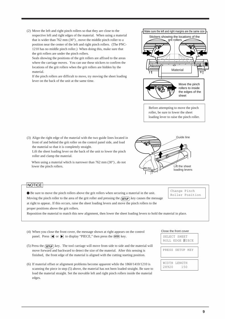
(2) Move the left and right pinch rollers so that they are close to therespective left and right edges of the material. When using a materialthat is wider than 762 mm (30") , move the middle pinch roller to aposition near the center of the left and right pinch rollers. (The PNC-1210 has no middle pinch roller.) When doing this, make sure thatthe grit rollers are under the pinch rollers.Seals showing the positions of the grit rollers are affixed to the areaswhere the carriage moves. You can use these stickers to confirm thelocations of the grit rollers when the grit rollers are hidden by thematerial.If the pinch rollers are difficult to move, try moving the sheet loadinglever on the back of the unit at the same time.
Move the pinch rollers to inside the edges of the sheet
Stickers showing the locations of the grit rollers
Make sure the left and right margins are the same size
(3) Align the right edge of the material with the two guide lines located infront of and behind the grit roller on the control panel side, and loadthe material so that it is completely straight.Lift the sheet loading lever on the back of the unit to lower the pinchroller and clamp the material.
Be sure to move the pinch rollers above the grit rollers when securing a material in the unit.
Moving the pinch roller to the area of the grit roller and pressing the SETUP key causes the message
at right to appear.. If this occurs, raise the sheet loading levers and move the pinch rollers to the
proper positions above the grit rollers.
Reposition the material to match this new alignment, then lower the sheet loading levers to hold the material in place.
Change PinchRoller Position
(4) When you close the front cover, the message shown at right appears on the controlpanel. Press or to display “PIECE,” then press the ENTER key.
(5) Press the SETUP key. The tool carriage will move from side to side and the material willmove forward and backward to detect the size of the material. After this sensing isfinished, the front edge of the material is aligned with the cutting starting position.
(6) If material offset or alignment problems become apparent while the 1860/1410/1210 isscanning the piece in step (5) above, the material has not been loaded straight. Be sure toload the material straight. Set the movable left and right pinch rollers inside the materialedges.
Close the front cover
SELECT SHEETROLL EDGE PIECE
WIDTH LENGTH28920 150
PRESS SETUP KEY
When using a material which is narrower than 762 mm (30") , do notlower the pinch rollers.
Guide line
Before attempting to move the pinchroller, be sure to lower the sheetloading lever to raise the pinch roller.
Lift the sheetloading levers
Material
10
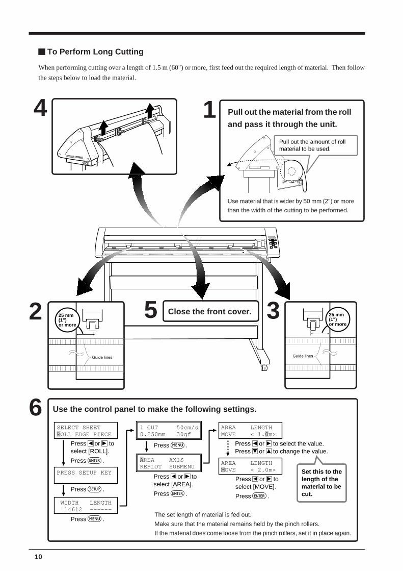
To Perform Long Cutting
AREA LENGTHMOVE < 1.0m>
AREA LENGTHMOVE < 2.0m>
1 CUT 50cm/s0.250mm 30gf
WIDTH LENGTH 14612 ------
PRESS SETUP KEY
SELECT SHEETROLL EDGE PIECE
AREA AXISREPLOT SUBMENU
Press .
Press .
Press
Press or to
.
Press .select [ROLL].
Press .
Press or toselect [AREA].
Press .
Press or toselect [MOVE].
Press or to select the value.Press or to change the value.
Set this to thelength of thematerial to becut.
Use the control panel to make the following settings.6
The set length of material is fed out.
Make sure that the material remains held by the pinch rollers.
If the material does come loose from the pinch rollers, set it in place again.
2 3
Guide lines
25 mm(1")or more
Guide lines
25 mm(1")or more
1 Pull out the material from the roll
and pass it through the unit.
5 Close the front cover.
Use material that is wider by 50 mm (2") or more
than the width of the cutting to be performed.
Pull out the amount of roll material to be used.
4
When performing cutting over a length of 1.5 m (60") or more, first feed out the required length of material. Then follow
the steps below to load the material.
11
Press MENU .
(8)PROTOCOL 1STOP DATA PARITY
PROTOCOL 2BAUD HANDSHAKE
AREA AXISREPLOT SUBMENU
VS-COMND FS-CMNDCOMAAND I/O
Use or to select.
Press ENTER .
Use or to select.
Press ENTER .
Press MENU twice.
(3), (4)
(5)
(6)
(7)
Use or to select.
Press ENTER .
CROPMARK UPDOWNOVER-CUT CALIB
INTERFACE PARA SERI<AUTO>
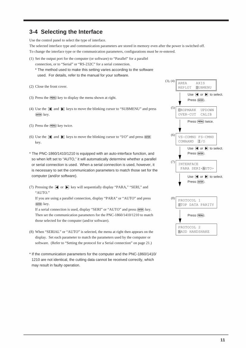
(1) Set the output port for the computer (or software) to “Parallel” for a parallel
connection, or to “Serial” or “RS-232C” for a serial connection.
* The method used to make this setting varies according to the software
used. For details, refer to the manual for your software.
(2) Close the front cover.
(3) Press the MENU key to display the menu shown at right.
(4) Use the and keys to move the blinking cursor to “SUBMENU” and press
ENTER key.
(5) Press the MENU key twice.
(6) Use the and keys to move the blinking cursor to “I/O” and press ENTER
key.
* The PNC-1860/1410/1210 is equipped with an auto-interface function, and
so when left set to “AUTO,” it will automatically determine whether a parallel
or serial connection is used. When a serial connection is used, however, it
is necessary to set the communication parameters to match those set for the
computer (and/or software).
(7) Pressing the or key will sequentially display “PARA,” “SERI,” and
“AUTO.”
If you are using a parallel connection, display “PARA” or “AUTO” and press
ENTER key.
If a serial connection is used, display “SERI” or “AUTO” and press ENTER key.
Then set the communication parameters for the PNC-1860/1410/1210 to match
those selected for the computer (and/or software).
(8) When “SERIAL” or “AUTO” is selected, the menu at right then appears on the
display. Set each parameter to match the parameters used by the computer or
software. (Refer to “Setting the protocol for a Serial connection” on page 21.)
* If the communication parameters for the computer and the PNC-1860/1410/
1210 are not identical, the cutting data cannot be received correctly, which
may result in faulty operation.
3-4 Selecting the InterfaceUse the control panel to select the type of interface.
The selected interface type and communication parameters are stored in memory even after the power is switched off.
To change the interface type or the communication parameters, configurations must be re-entered.
12
3-5 Cutting Test - Setting Cutting Speed, Blade Force, and Blade Compensation
For optimum performance, it is necessary to set cutting conditions that match the material, giving consideration to the material'sthickness and type of material. The PNC-1860/1410/1210 has an internal "cutting test" to check the cutting conditions. This“cutting test” allows you to determine settings for the cutting speed, blade force and the amount of offset.Experiment with different settings for different types of material and adjust the configuration accordingly.
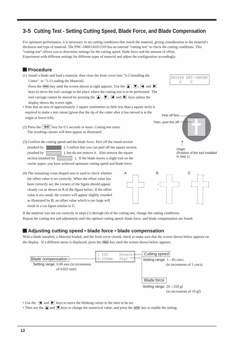
Procedure(1) Install a blade and load a material, then close the front cover (see "3-2 Installing the
Cutter" to "3-3 Loading the Material).
Press the MENU key until the screen shown at right appears. Use the , , and
keys to move the tool carriage to the place where the cutting test is to be performed. The
tool carriage cannot be moved by pressing the , , and keys unless the
display shows the screen right.
ORIGIN SET->ENTER O 0
Then, peel this off
Peel off first
Origin(Position of the tool installedin step 1)
Adjusting cutting speed • blade force • blade compensationWith a blade installed, a Material loaded, and the front cover closed, check to make sure that the screen shown below appears on
the display. If a different menu is displayed, press the MENU key until the screen shown below appears.
1 CUT 50cm/s0.250mm 30gf
• Use the and keys to move the blinking cursor to the item to be set.• Then use the and keys to change the numerical value, and press the ENTER key to enable the setting.
Setting range: 0.00 mm (in incrementsof 0.025 mm)
Setting range: 1—85 cm/s.(In increments of 1 cm/s)
Setting range: 20—350 gf (in increments of 10 gf)
Blade force
Cutting speedBlade compensation
• Note that an area of approximately 2 square centimeters (a little less than a square inch) is
required to make a test cutout (given that the tip of the cutter after it has moved is at the
origin at lower-left).
(4) The remaining cross-shaped area is used to check whether
the offset value is set correctly. When the offset value has
been correctly set, the corners of the figure should appear
cleanly cut as shown in A of the figure below. If the offset
value is too small, the corners will appear slightly rounded
as illustrated by B; an offset value which is too large will
result in a cut figure similar to C.
If the material was not cut correctly in steps (1) through (4) of the cutting test, change the cutting conditions.
Repeat the cutting test and adjustment until the optimal cutting speed, blade force, and blade compensation are found.
A B C
(2) Press the TEST key for 0.5 seconds or more. Cutting test starts.The resulting cutouts will then appear as illustrated.
(3) Confirm the cutting speed and the blade force. Peel off the round section
(marked by ). Confirm that you can peel off the square section
(marked by ), but do not remove it. Also remove the square
section (marked by ). If the blade leaves a slight trail on the
carrier paper, you have achieved optimum cutting speed and blade force.
13
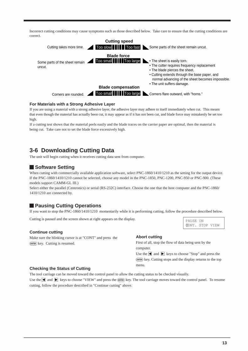
Cutting speed
Blade force
Blade compensation
Too fastToo slow
Too largeToo small
Too largeToo small
Cutting takes more time. Some parts of the sheet remain uncut.
• The sheet is easily torn.• The cutter requires frequency replacement• The blade pierces the sheet.• Cutting extends through the base paper, and normal advancing of the sheet becomes impossible.• The unit suffers damage.
Some parts of the sheet remain uncut.
Corners flare outward, with "horns."Corners are rounded.
Incorrect cutting conditions may cause symptoms such as those described below. Take care to ensure that the cutting conditions arecorrect.
For Materials with a Strong Adhesive LayerIf you are using a material with a strong adhesive layer, the adhesive layer may adhere to itself immediately when cut. This meansthat even though the material has actually been cut, it may appear as if it has not been cut, and blade force may mistakenly be set toohigh.If a cutting test shows that the material peels easily and the blade traces on the carrier paper are optimal, then the material isbeing cut. Take care not to set the blade force excessively high.
3-6 Downloading Cutting DataThe unit will begin cutting when it receives cutting data sent from computer.
Software SettingWhen cutting with commercially available application software, select PNC-1860/1410/1210 as the setting for the output device.If the PNC-1860/1410/1210 cannot be selected, choose any model in the PNC-1850, PNC-1200, PNC-950 or PNC-900. (Thesemodels support CAMM-GL III.)Select either the parallel (Centronics) or serial (RS-232C) interface. Choose the one that the host computer and the PNC-1860/1410/1210 are connected by.
Continue cuttingMake sure the blinking cursor is at "CONT" and press the
ENTER key. Cutting is resumed.
Pausing Cutting OperationsIf you want to stop the PNC-1860/1410/1210 momentarily while it is performing cutting, follow the procedure described below.
Checking the Status of CuttingThe tool carriage can be moved toward the control panel to allow the cutting status to be checked visually.
Use the and keys to choose "VIEW" and press the ENTER key. The tool carriage moves toward the control panel. To resume
cutting, follow the procedure described in "Continue cutting" above.
PAUSE ONCONT. STOP VIEW
Cutting is paused and the screen shown at right appears on the display.
Abort cuttingFirst of all, stop the flow of data being sent by the
computer.
Use the and keys to choose "Stop" and press the
ENTER key. Cutting stops and the display returns to the top
menu.
14
Continuing CuttingCutting after changing the materialAgain carry out the procedure described from “3-3 Loading the Material” to “3-6 Downloading Cutting Data” .* There is no need to perform the procedure described under “3-4 Selecting the Interface.” Also, if a material of the
same type is used, there is no need to perform a cutting test.
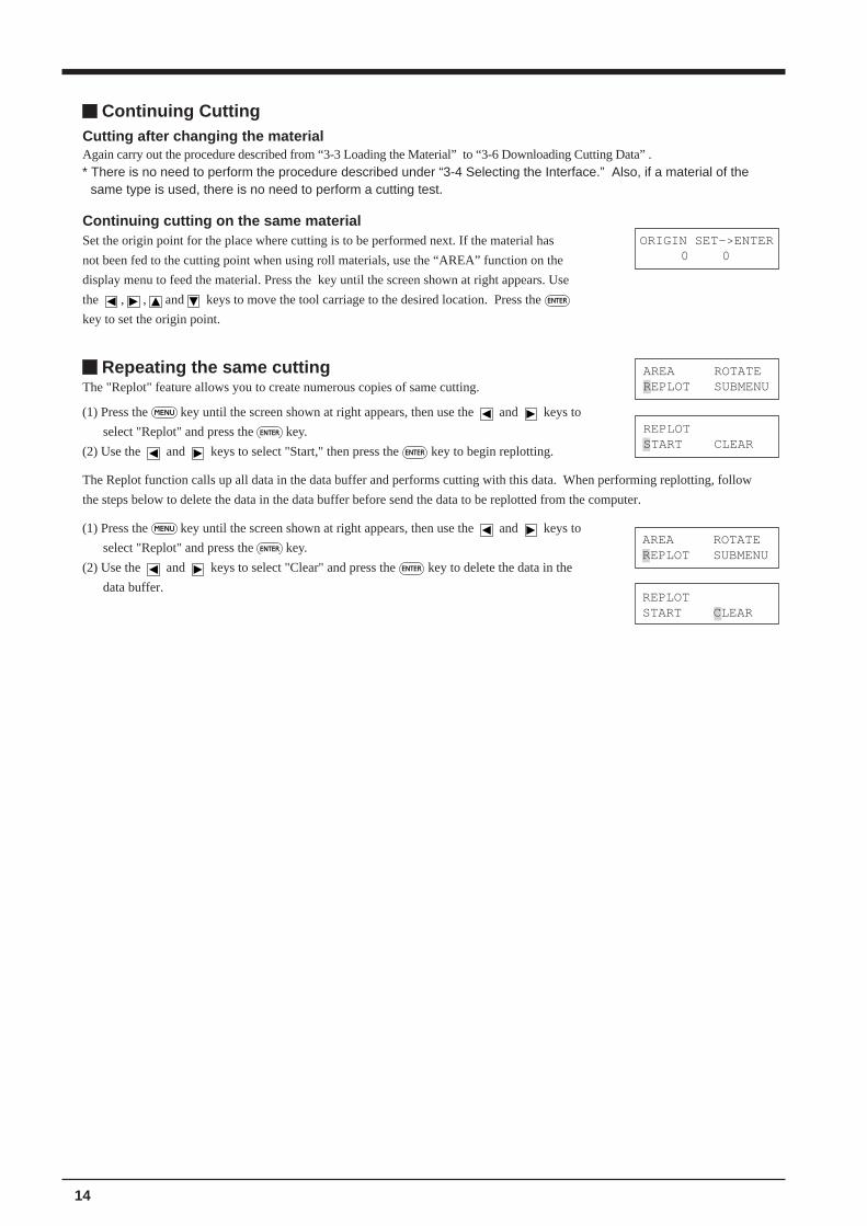
Continuing cutting on the same materialSet the origin point for the place where cutting is to be performed next. If the material has
not been fed to the cutting point when using roll materials, use the “AREA” function on the
display menu to feed the material. Press the key until the screen shown at right appears. Use
the , , and keys to move the tool carriage to the desired location. Press the ENTER
key to set the origin point.
ORIGIN SET->ENTER0 0
AREA ROTATEREPLOT SUBMENU
REPLOTSTART CLEAR
AREA ROTATEREPLOT SUBMENU
REPLOTSTART CLEAR
Repeating the same cuttingThe "Replot" feature allows you to create numerous copies of same cutting.
(1) Press the MENU key until the screen shown at right appears, then use the and keys to
select "Replot" and press the ENTER key.
(2) Use the and keys to select "Start," then press the ENTER key to begin replotting.
The Replot function calls up all data in the data buffer and performs cutting with this data. When performing replotting, follow
the steps below to delete the data in the data buffer before send the data to be replotted from the computer.
(1) Press the MENU key until the screen shown at right appears, then use the and keys to
select "Replot" and press the ENTER key.
(2) Use the and keys to select "Clear" and press the ENTER key to delete the data in the
data buffer.

15
3-7 Applying the Completed Cutout
(1) Open the front cover.For roll materialUse the cutter tool to cut off the completed portionfrom the roll.
For a Flat Material (Standard-sizeMaterial, Cut Material, Scrap, Piece, Etc.)Lower the sheet loading levers and remove thematerial from the PNC-1860/1410/1210.* If a portion that can still be cut remains, then
instead of removing the material, use the cuttertool included with the unit to detach the portionthat has been cut, just as is done when using arolled material.
(3) Stick application tape over the completed work.
Press down firmly or use a squeegee on the application
tape to remove air bubbles. If you do not press firmly
enough the cut area will not stick to the surface.
(4) Carefully apply the work at the desired location, while
keeping it as straight as possible. Rub over the
application tape to make sure the work is firmly stuck
in place. Then peel off the application tape.(2) Strip/Weed away all unneeded portions from the
completed work.
Tweezers
*You should have weedboarders or rectanglesdrawn around work tofacilitate weeding.
• Make sure beforehand that the surface where the work is to be stuck is clean and free of all dust or oily deposits.• When applying the work to a transparent surface, such as a window, you can use a water-based pen (which can be
wiped off) after wards to mark guidelines on the reverse side of the glass, to aid in getting the work alignedproperly.
• If you discover after it is stuck in place that air bubbles were trapped under the work, use a needle to puncture them.Then you can smooth out the material so that it sticks securely.
3-8 When Completed Cutting(1) When cutting is finished, press down the sheet loading
levers and remove the material.
Press down the sheet loading levers
Material
(2) If a cutter was used, wipe the cutter with a soft cloth toremove any pieces of the material that may be adheringto it.If a pen was used, remove the pen from the tool carriageand cap it securely.
(3) Turn the power off. If you not intended to used the unitfor an extended period of time, you should pull the plugfor the power cord out of the outlet.
16
Cleaning the bodyUse water or alcohol to clean, and wipe gently with a clean cloth. Wipe the operation panel and display gently with a clean, softcloth.
Cleaning the platenIf the platen is dirty clean with alcohol or water and wipe gently with a cloth.
Cleaning the grit rollersWith the sheet loading levers lowered and the pinch rollers raised, use a commerciallyavailable brush to remove dust and other detritus. Brush horizontally while rotating thegrit rollers.If dust builds up it may prevent the paper from being held securely, and degrade plotprecision.
Cleaning the pinch rollersWith the sheet loading levers lowered and the pinch rollers raised, use a cloth moistened with water or alcohol and wipe gentlyto clean.
Cleaning the front coverUse water or alcohol and clean with a soft cloth. If severe a neutral detergent may be used. Never use anything other than water,alcohol or a neutral detergent.
Cleaning the blade holder capIf material debris is adhering to the inner surface of the cap for the blade holder, loosen and remove the cap, then remove thematerial debris.
4 CARE AND MAINTENANCE
• Always turn off the PNC-1860/1410/1210 before cleaning it.• Never lubricate the mechanisms.• Use a small amount of water or alcohol for cleaning. Never use solvents such as benzene or thinner can smooth out the material
so that it sticks securely.
17
5 ABOUT THE CUTTING AREA
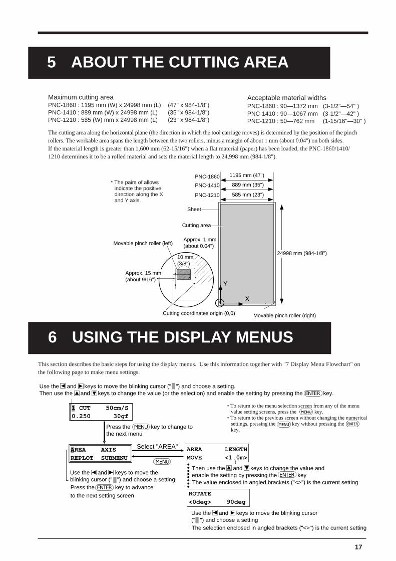
6 USING THE DISPLAY MENUSThis section describes the basic steps for using the display menus. Use this information together with "7 Display Menu Flowchart" onthe following page to make menu settings.
AREA AXISREPLOT SUBMENU
1 CUT 50cm/S0.250 30gf
MENU
ENTER
ENTER
Press the key to change to the next menu
AREA LENGTHMOVE <1.0m>
ROTATE <0deg> 90deg
ENTERThen use the and keys to change the value andenable the setting by pressing the key Use the and keys to move the
blinking cursor (" ") and choose a setting Press the key to advanceto the next setting screen
Select "AREA"
The value enclosed in angled brackets ("<>") is the current setting
The selection enclosed in angled brackets ("<>") is the current setting
MENU
Use the and keys to move the blinking cursor (" ") and choose a setting. Then use the and keys to change the value (or the selection) and enable the setting by pressing the key.
Use the and keys to move the blinking cursor (" ") and choose a setting
• To return to the menu selection screen from any of the menuvalue setting screens, press the MENU key.
• To return to the previous screen without changing the numericalsettings, pressing the MENU key without pressing the ENTER
key.
* The pairs of allowsindicate the positivedirection along the Xand Y axis.
Acceptable material widthsPNC-1860 : 90—1372 mm (3-1/2"—54" )PNC-1410 : 90—1067 mm (3-1/2"—42" )PNC-1210 : 50—762 mm (1-15/16"—30" )
The cutting area along the horizontal plane (the direction in which the tool carriage moves) is determined by the position of the pinchrollers. The workable area spans the length between the two rollers, minus a margin of about 1 mm (about 0.04") on both sides.If the material length is greater than 1,600 mm (62-15/16") when a flat material (paper) has been loaded, the PNC-1860/1410/1210 determines it to be a rolled material and sets the material length to 24,998 mm (984-1/8").
Maximum cutting areaPNC-1860 : 1195 mm (W) x 24998 mm (L) (47" x 984-1/8")PNC-1410 : 889 mm (W) x 24998 mm (L) (35" x 984-1/8")PNC-1210 : 585 (W) mm x 24998 mm (L) (23" x 984-1/8")
PNC-1860
PNC-1410
PNC-1210
1195 mm (47")
889 mm (35")
585 mm (23")
24998 mm (984-1/8")10 mm(3/8")
Approx. 1 mm(about 0.04")
Cutting coordinates origin (0,0)
Movable pinch roller (left)
Cutting area
Sheet
Movable pinch roller (right)
Approx. 15 mm(about 9/16")

18
WIDTH LENGTH 14612 ------
REPLOTSTART CLEAR
AXIS ROTATION<0deg> 90deg
AREA LENGTHMOVE < 1.0m>
1 CUT 50cm/s0.250mm 30gf
AREA AXISREPLOT SUBMENU
1— 8
0—1.000(in increments of 0.025 mm)
1—85 (in increments of 1 cm/s)
1—85 (in increments of 1 cm/s)NORMAL/HEAVY/ H-SPEED
20—350(in increments of 10 gf)
MENU
AREA
AXIS
REPLOT
-24.9 m—+24.9 m (in increments of 0.1 m.)* When [FEET] is selected for [AREAUNIT] : -82.17—+82.17 (in increments of 0.33 feet)
0deg / 90deg
START/CLEAR
ENTER
Top menu
Align the blinking cursor at the value, press or to change the value, then press to confirm.After making the setting for [LENGTH], press or to move the blinking cursor to [MOVE] and press ENTER
MENUMENU
to feed the sheet at the set length.
.
ENGLISH JAPANESEGERMAN FRENCH
DEMO CUT
SELECT SHEETROLL EDGE PIECE
PNC-1860 Roland DG Corp.
PRESS SETUP KEY LOADING SHEETROLL
Power on + Power on + Power on
Openning message
After loading a sheet, close the front cover.
ROLL/EDGE/PIECE
ENTERPress
MENU
SETUP
to select.Use or
MENU
to select.Use orENTER to enable the setting.Press
ENGLISH/JAPANESE/GERMAN/FRENCH/SPANISH/ITALIAN
SPANISH ITALIAN
PNC-1410 Roland DG Corp.
PNC-1210 Roland DG Corp.
UP 50cm/s NORMAL
CROPMARK SETTINGFAILED,SET AGAIN
CROPMARK SETTING COMPLETED!
ALIGNPOINT->ENTER 0 0
BASEPOINT->ENTER 0 0
CROP-MARK
7D
ISP
LAY M
EN
US
FLO
WC
HA
RT
For details about each of the m
enus, see the "8 Display M
enu Lists."
19
HANDSHAKE<H-WIRE>XON/OFF
BAUD RATE 19200 <9600>
PARITY MODE<NONE>ODD EVEN
DATA BIT 7 <8>
STOP BIT<1> 2
PROTOCOL 2 BAUD HANDSHAKE
PROTOCOL 1STOP DATA PARITY
ORIGIN SET->ENTER 0 0
PAUSE ONCONT. STOP VIEW
AREA MENU UNIT<METRE> FEET
INTERFACE PARA SERI<AUTO>
COMMAND MODE 1 2 <AUTO>
UNIT AREAUNITTOOL-CHG PREFEED
FS COMMAND<IGNRORE>EFFECT
VS COMMAND<IGNRORE>EFFECT
VS-CMND FS-CMNDCOMMAND I/O
MENU
MENU
FS-CMND
VS-CMND
PEN-CHG
IGNORE / ACCEPT
IGNORE / ACCEPT
IGNORE / ACCEPT
ENTER
MENU
MENU
COMMAND
I/O
AREAUNIT
SMOOTHING
1 (mode 1) / 2 (mode 2) / AUTO
PARA (Parallel) / SERI (Serial) / AUTO
MENU
1/2
7 / 8
NONE / EVEN / ODD
STOP
DATA
PARITY
BAUD
HAND-SHAKE
2400 / 4800 / 9600 / 19200
H-WIRE (Hardwire) / XON/OFF
METRE / FEET
MENU
Select [END.]Press .ENTER
Pressing moves the blade up or down.Pressing , , , or moves the cutter in the +Y, -Y, -X, or +X directions, respectively.
BAUD RATE 4800 2400
When set to [SERIAL] or [AUTO] (communication parameter setting)
PAUSE->ENTERPAUSE .Press
Use , , , and to move the tool carreage and sheet to the position on the sheet where the origin point is to be set.
ENTER to enable the setting.Press
MENUMENU
Cutting Machine is performing cutting
CONT: Cutting is continued (resumed)STOP: Cutting is stopped (cutting performed for data already received)VIEW: The tool carriage moves to the right side
DISPLAY UNIT<MACHINE> MILI
UNIT
MACHINE / MILI (Milimeter)
MENU
AUTO PREFEED<OFF> ONPREFEED
OFF / ON
OFF / ON
CALIB X CALIB Y 0.00% 0.00%
OVER CUT OFF <ON>
UP/DOWN ->ENTERMOVE ->CURSOR
CALIB
OVER CUT
UPDOWN
OFF/ON
-0.19% 0.19% (in increments of 0.01%.)
SUBMENU CROPMARK UPDOWNOVER-CUT CALIB
TOOL-CHG COMMAND<IGNORE> EFFECT
SMOOTHING END
SMOOTHING<OFF> ON

20
MENU Explanation Default Page where explained
Determining the type of sheet loaded
SELECT SHEET
This selects the type of sheet to be used ("Roll," "Edge," or "PIECE"). - 8, 9
Setting cutting conditions
1—8
It is possible to set the cutting parameters (plotting parameters) to match the tool and sheet (pen and paper condition), and store them for later use. Five items can be stored: cutting speed , blade compensation, blade force, tool movement speed during tool-up, and CUT QUALITY. These settings can be stored in memory as eight patterns (numbered 1 through 8).
- 11, 12, 23
** cm/sThis sets the speed blade for during cutting. Perform a cutting test and set the conditions to match the loaded sheet and the installed cutter. 50 cm/s 11, 12, 23
*.**mm
This sets the amount of offset for the blade during cutting. Perform a cutting test and set the conditions to match the loaded sheet and the installed cutter. When using the included test sheet and blade or equivalent parts, cutting can be performed using the factory-default settings.
0.250 mm 11, 12, 23
**gfThis sets the force for the blade during cutting. Perform a cutting test and set the conditions to match the loaded sheet and the installed cutter. 30 gf 11, 12, 23
SMOOTH-ING
If you want the curves of circles and arcs to be cut smoothly, set this to “ON.” When on, however, small text or intricate designs may also be cut with rounded corners. If this happens, change the setting to “OFF” and perform cutting again.
ON -
NORMAL(CUT QUALITY)
This sets the cutting quality. Ordinarily this is left set to "NORMAL." When rapid cutting is desired, such as when cutting a large sheet, set this to "HI-SPEED." When load is large, or if the sheet is not cut smoothly, or when small text is to be cut attractively, set this to "HEAVY."
NORMAL 25
UPSPEEDThis sets the speed of movement when the tool is raised and moves to the next position for cutting during a cutting operation. 85 cm/s -
1OVER CUT
g g gThis selection is normally left set to "OFF," and is set to "ON" when cutting especially attractive corners is desired. When cutting small text or intricate graphics, however, this should be set to "OFF" to avoid
OFF 20
Setting the origin point
ORIGIN SETSet a user origin at an arbitrary point on the sheet. After the sheet has been loaded, be sure to set the origin to the bottom left of the sheet.
- 13
Rotating the origin point
2AXIS ROTATION
This rotates the cutting coordinate origin by 90 degrees. This is normally set to “0deg,” which means that the origin is at the bottom left of the sheet. Setting this to “90deg” moves the origin to the bottom right of the sheet, thereby rotating the cutting pattern by 90 degrees.* Don’t forget that the coordinate axis changes when the origin is rotated.
0deg 20
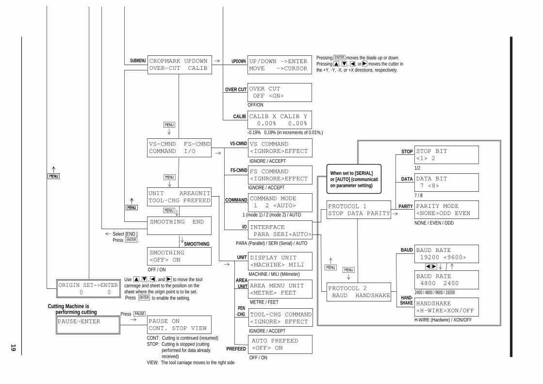
8 DISPLAY MENU LISTS
This chart lists the menus of the PNC-1860/1410/1210 grouped by usage. Menus indicated by an Circle (" ") are explainedfurther in the section at the end of the chart. Please refer to these additional explanations when using such menus.
21
MENU Explanation Default Page where explained
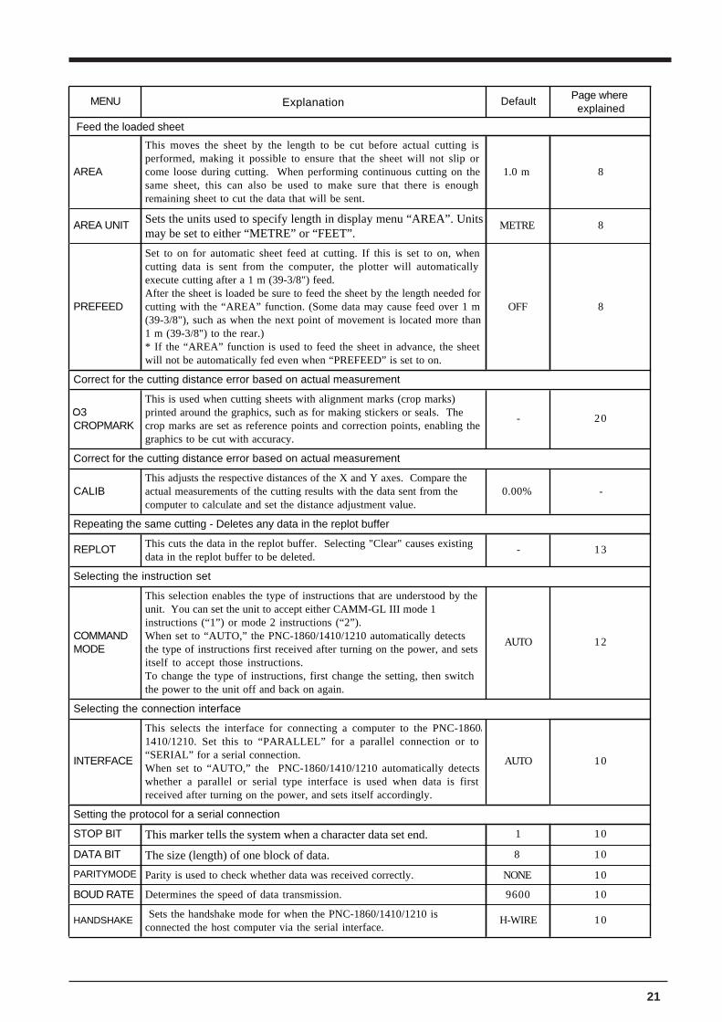
Feed the loaded sheet
AREA
This moves the sheet by the length to be cut before actual cutting is performed, making it possible to ensure that the sheet will not slip or come loose during cutting. When performing continuous cutting on the same sheet, this can also be used to make sure that there is enough remaining sheet to cut the data that will be sent.
1.0 m 8
AREA UNIT Sets the units used to specify length in display menu “AREA”. Unitsmay be set to either “METRE” or “FEET”.
METRE 8
PREFEED
Set to on for automatic sheet feed at cutting. If this is set to on, when cutting data is sent from the computer, the plotter will automatically execute cutting after a 1 m (39-3/8") feed.After the sheet is loaded be sure to feed the sheet by the length needed for cutting with the “AREA” function. (Some data may cause feed over 1 m (39-3/8"), such as when the next point of movement is located more than 1 m (39-3/8") to the rear.)* If the “AREA” function is used to feed the sheet in advance, the sheet will not be automatically fed even when “PREFEED” is set to on.
OFF 8
Correct for the cutting distance error based on actual measurement
3CROPMARK
This is used when cutting sheets with alignment marks (crop marks) printed around the graphics, such as for making stickers or seals. The crop marks are set as reference points and correction points, enabling the graphics to be cut with accuracy.
- 20
Correct for the cutting distance error based on actual measurement
CALIBThis adjusts the respective distances of the X and Y axes. Compare the actual measurements of the cutting results with the data sent from the computer to calculate and set the distance adjustment value.
0.00% -
Repeating the same cutting - Deletes any data in the replot buffer
REPLOT This cuts the data in the replot buffer. Selecting "Clear" causes existing data in the replot buffer to be deleted.
- 13
Selecting the instruction set
COMMAND MODE
This selection enables the type of instructions that are understood by the unit. You can set the unit to accept either CAMM-GL III mode 1 instructions (“1”) or mode 2 instructions (“2”).When set to “AUTO,” the PNC-1860/1410/1210 automatically detects the type of instructions first received after turning on the power, and sets itself to accept those instructions.To change the type of instructions, first change the setting, then switch the power to the unit off and back on again.
AUTO 12
Selecting the connection interface
INTERFACE
This selects the interface for connecting a computer to the PNC-1860/1410/1210. Set this to “PARALLEL” for a parallel connection or to “SERIAL” for a serial connection.When set to “AUTO,” the PNC-1860/1410/1210 automatically detects whether a parallel or serial type interface is used when data is first received after turning on the power, and sets itself accordingly.
AUTO 10
Setting the protocol for a serial connection
STOP BIT This marker tells the system when a character data set end. 1 10
DATA BIT The size (length) of one block of data. 8 10
PARITYMODE Parity is used to check whether data was received correctly. NONE 10
BOUD RATE Determines the speed of data transmission. 9600 10
HANDSHAKE Sets the handshake mode for when the PNC-1860/1410/1210 is connected the host computer via the serial interface.
H-WIRE 10
22
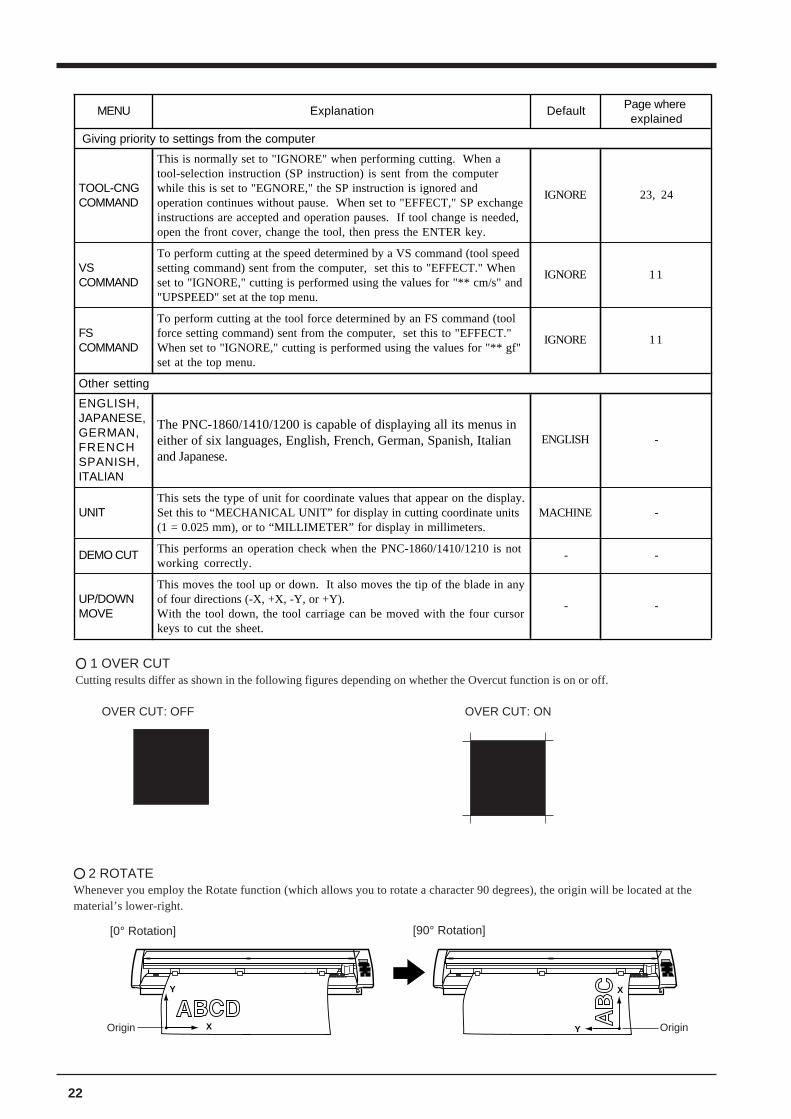
[90° Rotation]
Y
X Y
X
[0° Rotation]
2 ROTATEWhenever you employ the Rotate function (which allows you to rotate a character 90 degrees), the origin will be located at thematerial’s lower-right.
1 OVER CUTCutting results differ as shown in the following figures depending on whether the Overcut function is on or off.
MENU Explanation Default Page where explained
Giving priority to settings from the computer
TOOL-CNG COMMAND
This is normally set to "IGNORE" when performing cutting. When a tool-selection instruction (SP instruction) is sent from the computer while this is set to "EGNORE," the SP instruction is ignored and operation continues without pause. When set to "EFFECT," SP exchange instructions are accepted and operation pauses. If tool change is needed, open the front cover, change the tool, then press the ENTER key.
IGNORE 23, 24
VS COMMAND
To perform cutting at the speed determined by a VS command (tool speed setting command) sent from the computer, set this to "EFFECT." When set to "IGNORE," cutting is performed using the values for "** cm/s" and "UPSPEED" set at the top menu.
IGNORE 11
FS COMMAND
To perform cutting at the tool force determined by an FS command (tool force setting command) sent from the computer, set this to "EFFECT." When set to "IGNORE," cutting is performed using the values for "** gf" set at the top menu.
IGNORE 11
Other setting
ENGLISH, JAPANESE, GERMAN, FRENCH SPANISH, ITALIAN
The PNC-1860/1410/1200 is capable of displaying all its menus in either of six languages, English, French, German, Spanish, Italian and Japanese.
ENGLISH -
UNITThis sets the type of unit for coordinate values that appear on the display. Set this to “MECHANICAL UNIT” for display in cutting coordinate units (1 = 0.025 mm), or to “MILLIMETER” for display in millimeters.
MACHINE -
DEMO CUT This performs an operation check when the PNC-1860/1410/1210 is not working correctly.
- -
UP/DOWN MOVE
This moves the tool up or down. It also moves the tip of the blade in any of four directions (-X, +X, -Y, or +Y).With the tool down, the tool carriage can be moved with the four cursor keys to cut the sheet.
- -
OVER CUT: OFF OVER CUT: ON
Origin Origin
23
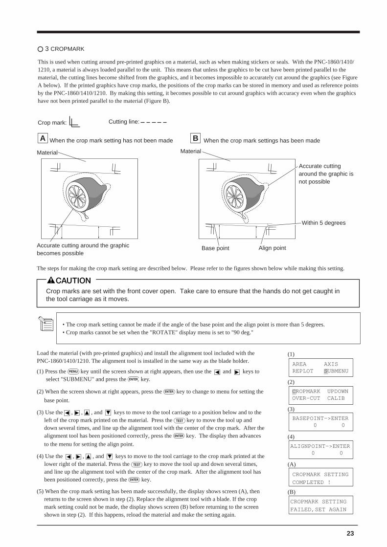
3 CROPMARK
This is used when cutting around pre-printed graphics on a material, such as when making stickers or seals. With the PNC-1860/1410/1210, a material is always loaded parallel to the unit. This means that unless the graphics to be cut have been printed parallel to thematerial, the cutting lines become shifted from the graphics, and it becomes impossible to accurately cut around the graphics (see FigureA below). If the printed graphics have crop marks, the positions of the crop marks can be stored in memory and used as reference pointsby the PNC-1860/1410/1210. By making this setting, it becomes possible to cut around graphics with accuracy even when the graphicshave not been printed parallel to the material (Figure B).
A When the crop mark setting has not been made B When the crop mark settings has been made
Crop mark: Cutting line:
AREA AXISREPLOT SUBMENU
(1)
(2)
CROPMARK SETTING
COMPLETED !
(3)
(4)
(A)
(B)
CROPMARK SETTING
FAILED,SET AGAIN
ALIGNPOINT->ENTER 0 0
BASEPOINT->ENTER 0 0
CROPMARK UPDOWNOVER-CUT CALIB
Material
Accurate cutting around the graphicbecomes possible
The steps for making the crop mark setting are described below. Please refer to the figures shown below while making this setting.
• The crop mark setting cannot be made if the angle of the base point and the align point is more than 5 degrees.• Crop marks cannot be set when the "ROTATE" display menu is set to "90 deg."
Crop marks are set with the front cover open. Take care to ensure that the hands do not get caught inthe tool carriage as it moves.
Load the material (with pre-printed graphics) and install the alignment tool included with thePNC-1860/1410/1210. The alignment tool is installed in the same way as the blade holder.
(1) Press the MENU key until the screen shown at right appears, then use the and keys toselect "SUBMENU" and press the ENTER key.
(2) When the screen shown at right appears, press the ENTER key to change to menu for setting the
base point.
(3) Use the , , , and keys to move to the tool carriage to a position below and to theleft of the crop mark printed on the material. Press the TEST key to move the tool up anddown several times, and line up the alignment tool with the center of the crop mark. After thealignment tool has been positioned correctly, press the ENTER key. The display then advances
to the menu for setting the align point.
(4) Use the , , , and keys to move to the tool carriage to the crop mark printed at thelower right of the material. Press the TEST key to move the tool up and down several times,and line up the alignment tool with the center of the crop mark. After the alignment tool hasbeen positioned correctly, press the ENTER key.
(5) When the crop mark setting has been made successfully, the display shows screen (A), thenreturns to the screen shown in step (2). Replace the alignment tool with a blade. If the cropmark setting could not be made, the display shows screen (B) before returning to the screenshown in step (2). If this happens, reload the material and make the setting again.
Material
Base point Align point
Within 5 degrees
Accurate cuttingaround the graphic isnot possible
24
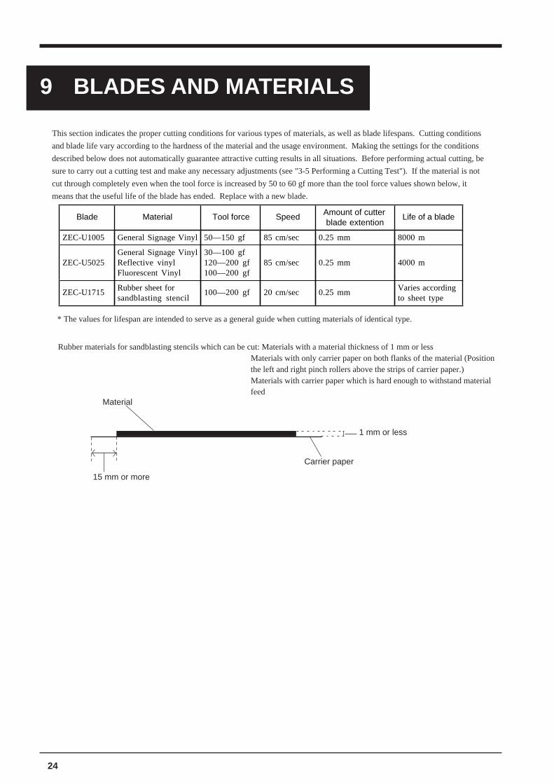
9 BLADES AND MATERIALS
* The values for lifespan are intended to serve as a general guide when cutting materials of identical type.
Material
Carrier paper
1 mm or less
15 mm or more
This section indicates the proper cutting conditions for various types of materials, as well as blade lifespans. Cutting conditions
and blade life vary according to the hardness of the material and the usage environment. Making the settings for the conditions
described below does not automatically guarantee attractive cutting results in all situations. Before performing actual cutting, be
sure to carry out a cutting test and make any necessary adjustments (see "3-5 Performing a Cutting Test"). If the material is not
cut through completely even when the tool force is increased by 50 to 60 gf more than the tool force values shown below, it
means that the useful life of the blade has ended. Replace with a new blade.
Blade Material Tool force Speed Amount of cutter blade extention
Life of a blade
ZEC-U1005 General Signage Vinyl 50—150 gf 85 cm/sec 0.25 mm 8000 m
ZEC-U5025General Signage VinylReflective vinylFluorescent Vinyl
30—100 gf120—200 gf100—200 gf
85 cm/sec 0.25 mm 4000 m
ZEC-U1715 Rubber sheet for sandblasting stencil
100—200 gf 20 cm/sec 0.25 mm Varies according to sheet type
Rubber materials for sandblasting stencils which can be cut: Materials with a material thickness of 1 mm or lessMaterials with only carrier paper on both flanks of the material (Positionthe left and right pinch rollers above the strips of carrier paper.)Materials with carrier paper which is hard enough to withstand materialfeed
25
Before cutting, plotting using pen and paper can ensure that your design is correct without wasting materials.This feature can also be used to plot template designs on thick materials that may not be able to be cut.* Since the design of the PNC-1860/1410/1210 differs inherently from that of dedicated plotters, it does not accommodate
functions such as high-speed plotting, automatic pen changes, pen dry protection, or the like.
Acceptable pens and paper media
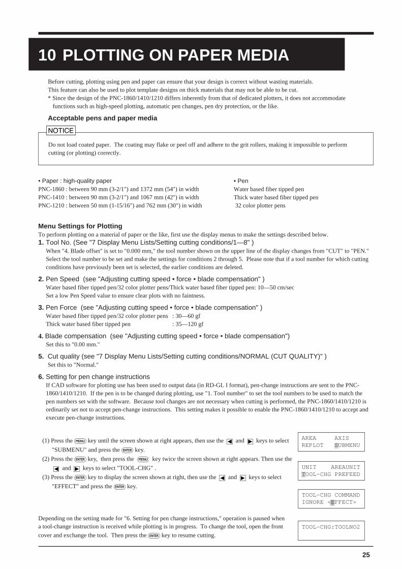
Depending on the setting made for "6. Setting for pen change instructions," operation is paused whena tool-change instruction is received while plotting is in progress. To change the tool, open the front
cover and exchange the tool. Then press the ENTER key to resume cutting.
Do not load coated paper. The coating may flake or peel off and adhere to the grit rollers, making it impossible to performcutting (or plotting) correctly.
UNIT AREAUNITTOOL-CHG PREFEED
AREA AXISREPLOT SUBMENU
TOOL-CHG COMMANDIGNORE <EFFECT>
• Paper : high-quality paperPNC-1860 : between 90 mm (3-2/1") and 1372 mm (54") in widthPNC-1410 : between 90 mm (3-2/1") and 1067 mm (42") in widthPNC-1210 : between 50 mm (1-15/16") and 762 mm (30") in width
• PenWater based fiber tipped penThick water based fiber tipped pen 32 color plotter pens
(1) Press the MENU key until the screen shown at right appears, then use the and keys to select
"SUBMENU" and press the ENTER key.
(2) Press the ENTER key, then press the MENU key twice the screen shown at right appears. Then use the
and keys to select "TOOL-CHG" .
(3) Press the ENTER key to display the screen shown at right, then use the and keys to select
"EFFECT" and press the ENTER key.
Menu Settings for PlottingTo perform plotting on a material of paper or the like, first use the display menus to make the settings described below.1. Tool No. (See "7 Display Menu Lists/Setting cutting conditions/1—8" )
When "4. Blade offset" is set to "0.000 mm," the tool number shown on the upper line of the display changes from "CUT" to "PEN."Select the tool number to be set and make the settings for conditions 2 through 5. Please note that if a tool number for which cuttingconditions have previously been set is selected, the earlier conditions are deleted.
2. Pen Speed (see "Adjusting cutting speed • force • blade compensation" )Water based fiber tipped pen/32 color plotter pens/Thick water based fiber tipped pen: 10—50 cm/secSet a low Pen Speed value to ensure clear plots with no faintness.
3. Pen Force (see "Adjusting cutting speed • force • blade compensation" )Water based fiber tipped pen/32 color plotter pens : 30—60 gfThick water based fiber tipped pen : 35—120 gf
4. Blade compensation (see "Adjusting cutting speed • force • blade compensation")Set this to "0.00 mm."
5. Cut quality (see "7 Display Menu Lists/Setting cutting conditions/NORMAL (CUT QUALITY)" )Set this to "Normal."
6. Setting for pen change instructionsIf CAD software for plotting use has been used to output data (in RD-GL I format), pen-change instructions are sent to the PNC-1860/1410/1210. If the pen is to be changed during plotting, use "1. Tool number" to set the tool numbers to be used to match thepen numbers set with the software. Because tool changes are not necessary when cutting is performed, the PNC-1860/1410/1210 isordinarily set not to accept pen-change instructions. This setting makes it possible to enable the PNC-1860/1410/1210 to accept andexecute pen-change instructions.
10 PLOTTING ON PAPER MEDIA
TOOL-CHG:TOOLNO2
26
11 WHAT TO DO IF....
11-1 What to do if....
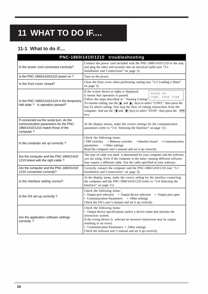
PNC-1860/1410/1210 troubleshooting
Is the power cord connected correctly?Connect the power cord included with the PNC-1860/1410/1210 to the unit, and plug the other end securely into an electrical outlet (see “3-1 Installation and Connections” on page 3).
Is the PNC-1860/1410/1210 power on ? Turn on the power.
Is the front cover closed? Close the front cover when performing cutting (see “3-3 Loading a Sheet” on page 5).
Is the PNC-1860/1410/1210 in the temporary halt state ? Is operation paused?
If the screen shown at rights is displayed, it means that operation is paused.Follow the steps described in " Pausing Cutting"To resume cutting, use the and keys to select "CONT," then press the key.To abord cutting, first stop the flow of cutting instructions from the computer. And use the and keys to select "STOP," then press the key.
If connected via the serial port, do the communication parameters for the PNC-1860/1410/1210 match those of the computer ?
At the display menus, make the correct settings for the communication parameters (refer to “3-4 Selecting the Interface” on page 11).
Is the computer set up correctly ?
Check the following items:• DIP switches • Memory switches • Interface board • Communication parameters • Other settingsRead the computer user’s manual and set it up correctly.
Are the computer and the PNC-1860/1410/1210 linked with the right cable ?
The type of cable you need is determined by your computer and the software you are using. Even if the computer is the same, running different software may require a different cable. Use the cable specified in your software.
Are the computer and the PNC-1860/1410/1210 connected correctly?
Correctly connect the computer and the PNC-1860/1410/1210 (see “3-1 Installation and Connections” on page 3).
Is the interface setting correct?At the display menu, make the correct setting for the interface connecting the computer and the PNC-1860/1410/1210 (refer to “3-4 Selecting the Interface” on page 11).
Is the OS set up correctly ?
Check the following items:• Output port selection • Output device selection • Output port open • Communication Parameters • Other settingsCheck the OS’s user’s manual and set it up correctly.
Are the application software settings correctly ?
Check the following items:• Output device specifications (select a device name that matches the instruction system. If the wrong device is selected an incorrect instruction may be output, resulting in an error).• Communication Parameters • Other settingsCheck the software user’s manual and set it up correctly.
PAUSE ONCONT. STOP VIEW
ENTER
27
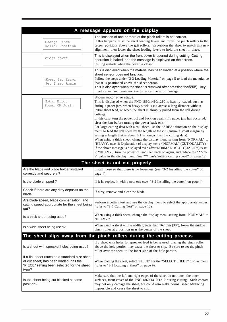
A message appears on the displayThe location of one or more of the pinch rollers is not correct.If this happens, raise the sheet loading levers and move the pinch rollers to the proper positions above the grit rollers. Reposition the sheet to match this new alignment, then lower the sheet loading levers to hold the sheet in place.
This is displayed when the front cover is opened during cutting. Cutting operation is halted, and the message is displayed on the screen.Cutting restarts when the cover is closed.
This is displayed when the material has been loaded at a position where the sheet sensor does not function. Follow the steps under "3-3 Loading Material" on page 5 to load the material so that it is positioned above the sheet sensor.This is displayed when the sheet is removed after pressing the key.Load a sheet and press any key to cancel the error message.
Shows motor error status.This is displayed when the PNC-1860/1410/1210 is heavily loaded, such as during a paper jam, when heavy stock is cut across a long distance without initial sheet feed, or when the sheet is abruptly pulled from the roll during cutting.In this case, turn the power off and back on again (if a paper jam has occurred, clear the jam before turning the power back on).For large cutting data with a roll sheet, use the “AREA” function on the display menu to feed the roll sheet by the length of the cut (ensure a small margin by setting a length that is about 0.1 m longer than the cutting data).When using a thick sheet, change the display menu setting from "NORMAL" to "HEAVY."(see “8 Explanation of display menu /"NORMAL" (CUT QUALITY) . If the above message is displayed even after"NORMAL" (CUT QUALITY) is set to “HEAVY,” turn the power off and then back on again, and reduce the “**cm/s” value in the display menu. See “** cm/s Setting cutting speed” on page 12.
The sheet is not cut properlyAre the blade and blade holder installed correctly and securely ?
Install these so that there is no looseness (see “3-2 Installing the cutter” on page 4).
Is the blade chipped ? If it is, replace it with a new one (see “3-2 Installing the cutter” on page 4).
Check if there are any dirty deposits on the blade.
If dirty, remove and clear the blade.
Are blade speed, blade compensation, and cutting speed appropriate for the sheet being cut?
Perform a cutting test and use the display menu to select the appropriate values (refer to “3-5 Cutting Test” on page 12).
Is a thick sheet being used? When using a thick sheet, change the display menu setting from "NORMAL" to "HEAVY."
Is a wide sheet being used? When using a sheet with a width greater than 762 mm (30"), lower the middle pinch roller at a position near the center of the sheet.
The sheet slips away from the pinch rollers during the cutting process
Is a sheet with sprocket holes being used?If a sheet with holes for sprocket feed is being used, placing the pinch roller above the hole portion may cause the sheet to slip. Be sure to set the pinch roller over the sheet to the inner side of the hole portion.
If a flat sheet (such as a standard-size sheet or cut sheet) has been loaded, has the “PIECE” setting been selected for the sheet type?
When loading the sheet, select “PIECE” for the “SELECT SHEET” display menu (refer to “3-3 Loading a Sheet” on page 9).
Is the sheet being cut blocked at some position?
Make sure that the left and right edges of the sheet do not touch the inner surfaces, front cover of the PNC-1860/1410/1210 during cutting. Such contact may not only damage the sheet, but could also make normal sheet advancing impossible and cause the sheet to slip.
Change PinchRoller Position
CLOSE COVER
Sheet Set ErrorSet Sheet Again
Motor ErrorPower ON Again
SETUP
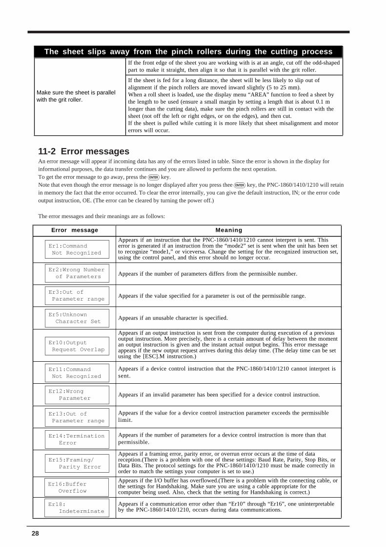
28
The sheet slips away from the pinch rollers during the cutting process
Make sure the sheet is parallel with the grit roller.
If the front edge of the sheet you are working with is at an angle, cut off the odd-shaped part to make it straight, then align it so that it is parallel with the grit roller.
If the sheet is fed for a long distance, the sheet will be less likely to slip out of alignment if the pinch rollers are moved inward slightly (5 to 25 mm).When a roll sheet is loaded, use the display menu “AREA” function to feed a sheet by the length to be used (ensure a small margin by setting a length that is about 0.1 m longer than the cutting data), make sure the pinch rollers are still in contact with the sheet (not off the left or right edges, or on the edges), and then cut.If the sheet is pulled while cutting it is more likely that sheet misalignment and motor errors will occur.
11-2 Error messagesAn error message will appear if incoming data has any of the errors listed in table. Since the error is shown in the display forinformational purposes, the data transfer continues and you are allowed to perform the next operation.To get the error message to go away, press the ENTER key.Note that even though the error message is no longer displayed after you press thee ENTER key, the PNC-1860/1410/1210 will retainin memory the fact that the error occurred. To clear the error internally, you can give the default instruction, IN; or the error codeoutput instruction, OE. (The error can be cleared by turning the power off.)
The error messages and their meanings are as follows:
Error message Meaning
Appears if an instruction that the PNC-1860/1410/1210 cannot interpret is sent. This error is generated if an instruction from the “mode2” set is sent when the unit has been set to recognize “mode1,” or viceversa. Change the setting for the recognized instruction set, using the control panel, and this error should no longer occur.
Appears if the number of parameters differs from the permissible number.
Appears if the value specified for a parameter is out of the permissible range.
Appears if an unusable character is specified.
Appears if an output instruction is sent from the computer during execution of a previous output instruction. More precisely, there is a certain amount of delay between the moment an output instruction is given and the instant actual output begins. This error message appears if the new output request arrives during this delay time. (The delay time can be set using the [ESC].M instruction.)
Appears if a device control instruction that the PNC-1860/1410/1210 cannot interpret is sent.
Appears if an invalid parameter has been specified for a device control instruction.
Appears if the value for a device control instruction parameter exceeds the permissible limit.
Appears if the number of parameters for a device control instruction is more than that permissible.
Appears if a framing error, parity error, or overrun error occurs at the time of data reception.(There is a problem with one of these settings: Baud Rate, Parity, Stop Bits, or Data Bits. The protocol settings for the PNC-1860/1410/1210 must be made correctly in order to match the settings your computer is set to use.)
Appears if the I/O buffer has overflowed.(There is a problem with the connecting cable, or the settings for Handshaking. Make sure you are using a cable appropriate for the computer being used. Also, check that the setting for Handshaking is correct.)
Appears if a communication error other than “Er10” through “Er16”, one uninterpretable by the PNC-1860/1410/1210, occurs during data communications.
Er1:Command Not Recognized
Er2:Wrong Number of Parameters
Er3:Out of Parameter range
Er5:Unknown Character Set
Er10:Output Request Overlap
Er11:Command Not Recognized
Er12:Wrong Parameter
Er13:Out of Parameter range
Er14:Termination Error
Er15:Framing/ Parity Error
Er18: Indeterminate
Er16:Buffer Overflow
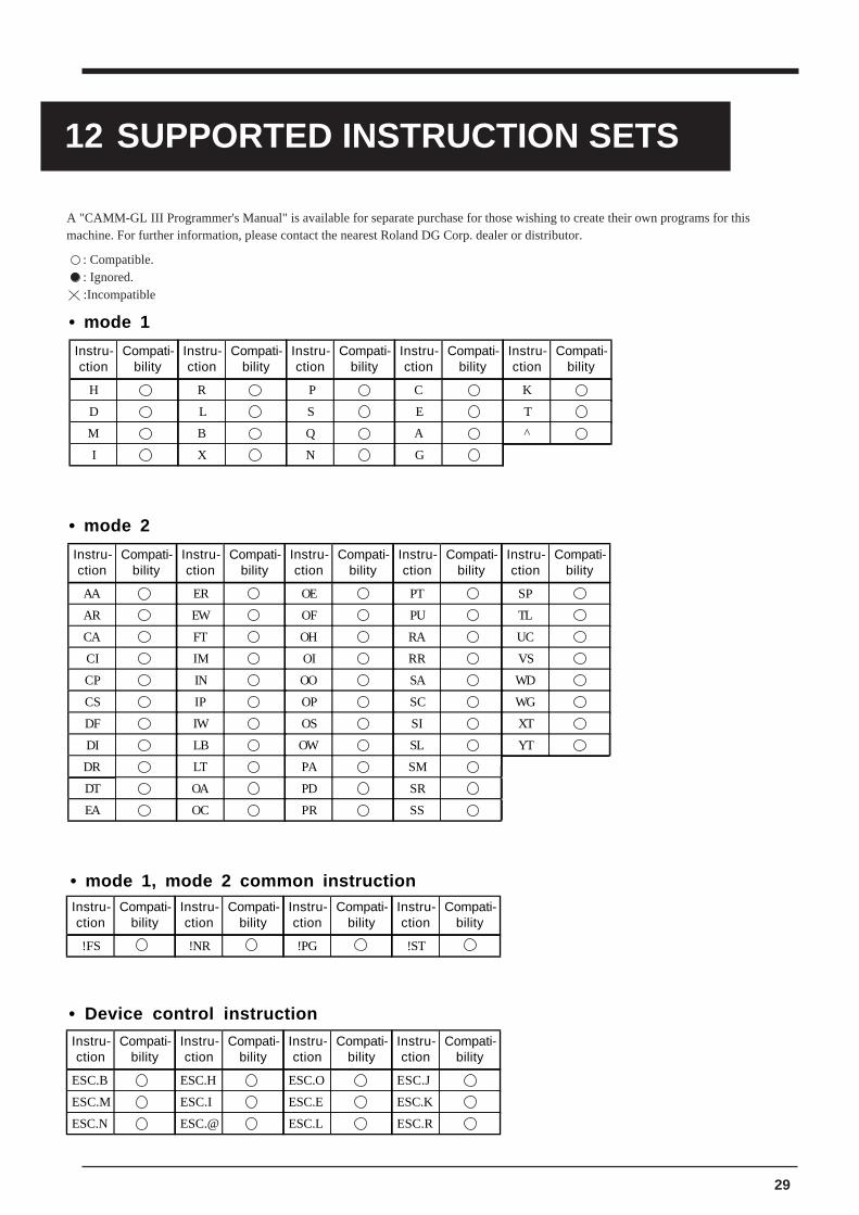
29
12 SUPPORTED INSTRUCTION SETS
A "CAMM-GL III Programmer's Manual" is available for separate purchase for those wishing to create their own programs for thismachine. For further information, please contact the nearest Roland DG Corp. dealer or distributor.
: Compatible. : Ignored.
:Incompatible
Instru-ction
Compati-bility
Instru-ction
Compati-bility
Instru-ction
Compati-bility
Instru-ction
Compati-bility
Instru-ction
Compati-bility
H R P C K
D L S E T
M B Q A ^
I X N G
Instru-ction
Compati-bility
Instru-ction
Compati-bility
Instru-ction
Compati-bility
Instru-ction
Compati-bility
Instru-ction
Compati-bility
AA ER OE PT SP
AR EW OF PU TL
CA FT OH RA UC
CI IM OI RR VS
CP IN OO SA WD
CS IP OP SC WG
DF IW OS SI XT
DI LB OW SL YT
DR LT PA SM
DT OA PD SR
EA OC PR SS
Instru-ction
Compati-bility
Instru-ction
Compati-bility
Instru-ction
Compati-bility
Instru-ction
Compati-bility
ESC.B ESC.H ESC.O ESC.J
ESC.M ESC.I ESC.E ESC.K
ESC.N ESC.@ ESC.L ESC.R
Instru-ction
Compati-bility
Instru-ction
Compati-bility
Instru-ction
Compati-bility
Instru-ction
Compati-bility
!FS !NR !PG !ST
• mode 1
• mode 2
• mode 1, mode 2 common instruction
• Device control instruction

30
Automatic backspace
13 CHARACTER SET
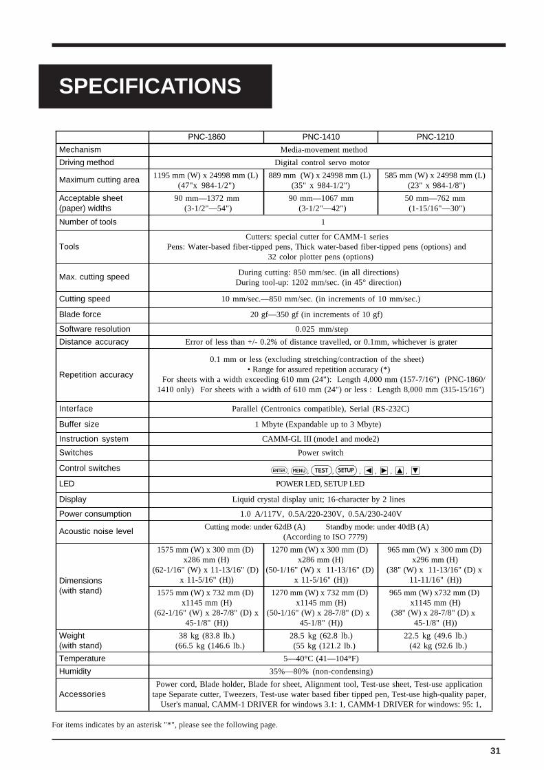
31
PNC-1860 PNC-1410 PNC-1210
Mechanism Media-movement method
Driving method Digital control servo motor
Maximum cutting area 1195 mm (W) x 24998 mm (L) (47"x 984-1/2")
889 mm (W) x 24998 mm (L) (35" x 984-1/2")
585 mm (W) x 24998 mm (L) (23" x 984-1/8")
Acceptable sheet (paper) widths
90 mm—1372 mm (3-1/2"—54")
90 mm—1067 mm (3-1/2"—42")
50 mm—762 mm (1-15/16"—30")
Number of tools 1
ToolsCutters: special cutter for CAMM-1 series
Pens: Water-based fiber-tipped pens, Thick water-based fiber-tipped pens (options) and 32 color plotter pens (options)
Max. cutting speed During cutting: 850 mm/sec. (in all directions) During tool-up: 1202 mm/sec. (in 45° direction)
Cutting speed 10 mm/sec.—850 mm/sec. (in increments of 10 mm/sec.)
Blade force 20 gf—350 gf (in increments of 10 gf)
Software resolution 0.025 mm/step
Distance accuracy Error of less than +/- 0.2% of distance travelled, or 0.1mm, whichever is grater
Repetition accuracy
0.1 mm or less (excluding stretching/contraction of the sheet) • Range for assured repetition accuracy (*)
For sheets with a width exceeding 610 mm (24"): Length 4,000 mm (157-7/16") (PNC-1860/1410 only) For sheets with a width of 610 mm (24") or less : Length 8,000 mm (315-15/16")
Interface Parallel (Centronics compatible), Serial (RS-232C)
Buffer size 1 Mbyte (Expandable up to 3 Mbyte)
Instruction system CAMM-GL III (mode1 and mode2)
Switches Power switch
Control switches
LED POWER LED, SETUP LED
Display Liquid crystal display unit; 16-character by 2 lines
Power consumption 1.0 A/117V, 0.5A/220-230V, 0.5A/230-240V
Acoustic noise level Cutting mode: under 62dB (A) Standby mode: under 40dB (A)(According to ISO 7779)
Dimensions(with stand)
1575 mm (W) x 300 mm (D) x286 mm (H)
(62-1/16" (W) x 11-13/16" (D) x 11-5/16" (H))
1270 mm (W) x 300 mm (D) x286 mm (H)
(50-1/16" (W) x 11-13/16" (D) x 11-5/16" (H))
965 mm (W) x 300 mm (D) x296 mm (H)
(38" (W) x 11-13/16" (D) x 11-11/16" (H))
1575 mm (W) x 732 mm (D) x1145 mm (H)
(62-1/16" (W) x 28-7/8" (D) x45-1/8" (H))
1270 mm (W) x 732 mm (D) x1145 mm (H)
(50-1/16" (W) x 28-7/8" (D) x 45-1/8" (H))
965 mm (W) x732 mm (D) x1145 mm (H)
(38" (W) x 28-7/8" (D) x 45-1/8" (H))
Weight(with stand)
38 kg (83.8 lb.)(66.5 kg (146.6 lb.)
28.5 kg (62.8 lb.)(55 kg (121.2 lb.)
22.5 kg (49.6 lb.)(42 kg (92.6 lb.)
Temperature 5—40°C (41—104°F)
Humidity 35%—80% (non-condensing)
AccessoriesPower cord, Blade holder, Blade for sheet, Alignment tool, Test-use sheet, Test-use application
tape Separate cutter, Tweezers, Test-use water based fiber tipped pen, Test-use high-quality paper, User's manual, CAMM-1 DRIVER for windows 3.1: 1, CAMM-1 DRIVER for windows: 95: 1,
SPECIFICATIONS
For items indicates by an asterisk "*", please see the following page.
ENTER , MENU , TEST , SETUP , , , ,
SPECIFICATIONS

32
Signal Number
Terminal Number
Signal Number Pin Connection
NC 36 18 HIGH**
HIGH* 35 17 GND
NC 34 16 GND
GND 33 15 NC
HIGH* 32 14 NC
NC 31 13 HIGH*
GND
30 12 GND
29 11 BUSY
28 10 ACK
27 9 D7
26 8 D6
25 7 D5
24 6 D4
23 5 D3
22 4 D2
21 3 D1
20 2 D0
19 1 STROBE
Parallel
Standard In compliance with the specifications of Centronics
Input signals STROBE (1 BIT), DATA (8 BIT)
Output signals BUSY (1 BIT), ACK (1 BIT)
Level of input/output signals TTL level
Transmission method Asynchronous
Serial
Standard RS-232C specifications
Transmission method Asynchronous, duplex data transmission
Transmission speed 2400, 4800, 9600, 19200 (selected using panel keys)
Parity check Odd, Even, or None (selected using panel keys)
Data bits 7 or 8 bits (selected using panel keys)
Stop bits 1 or 2 bits (selected using panel keys)
Handshake DTR or Xon/Xoff (selected using panel keys)
Signal Number
Terminal Number
Signal Number Pin Connection
NC 25 13 NC
NC 24 12 NC
NC 23 11 NC
NC 22 10 NC
NC 21 9 NC
DTR 20 8 NC
NC 19 7 SG
NC 18 6 DSR
NC 17 5 CTS
NC 16 4 RTS
NC 15 3 RXD
NC 14 2 TXD
1 FG
(* ) The following conditions must be satisfied:- Material type: 3M Scotchcal Mastercut Film, ARLON Series 2100- Special stand (a roll material must be set at the rear and on the inner sheet hanger)- Side margins: 25 mm (1") or more for both the left and right margins- Front margin: 25 mm (1") or more(After loading the material, using the display menu to select “EDGE” as the material type automatically sets a front margin of 25 mm (1").)- Use of the display menu’s “AREA” function to perform feed of the material length plus 0.2 m and set the material correctly- Cutting of the following data one time
X
Y
Origin
(1) The letters are cut in order starting with "R"(2) After the last letter ("P") has been cut, the machine returns to the origin point and the outer border is cut
The origin is rotated 90 degrees ("AXIS" on the display menu is set to "90deg").
Feed lengthSheets with a width exceeding 610 mm (24"): 4,000 mm (157-7/16")Sheets with a width of 610 mm (24") or less : 8,000 mm (315-15/16")
Cut lengthFills the hard clip
Front margin: 25 mm (1") or more
Side margins: 25 mm (1") or more
Side margins: 25 mm (1") or more
Movable pinch roller (left)
Movable pinch roller (right)
Cutter protector
Interface Specifications
Specification of the Parallel interface Specification of the Serial interface
3.3K
100
+5 V
+5 V
=
=
*
**
Ω
Ω
1
19
18
36
1
14
13
25

R9-980506