roll-feed granulator - plastic granulators, industrial ... · sgf-26 series roll-feed granulator...
TRANSCRIPT

SGF-26 series Roll-feed Granulator
Date: Mar, 2013
Version: Ver.A (English)

3(70)
Contents
1. General Description .....................................................................................8
1.1 Coding Principle ......................................................................................9
1.2 Feature....................................................................................................9
1.3 Technical Specifications........................................................................11
1.3.1 Technical Specifications .............................................................11
1.3.2 Dimensions.................................................................................12
1.4 Safety Regulations ................................................................................13
1.4.1 Safety Signs and Labels .............................................................13
1.4.2 Transportation and Storage of the Machine................................15
1.5 Exemption Clause.................................................................................17
2. Structural Features and Working Principle ..............................................18
2.1 General Description ..............................................................................18
2.1.1 Working Principle........................................................................18
2.2 Safety System.......................................................................................19
2.2.1 Emergency Stop Switch..............................................................19
2.2.2 Safety Switch..............................................................................20
2.2.3 Lock ............................................................................................20
2.3 Assembly Drawing ................................................................................22
2.3.1 Assembly Drawing ......................................................................22
2.3.2 Parts List.....................................................................................23
2.3.3 Cutting Chamber.........................................................................24
2.3.4 Cutting Chamber Parts List.........................................................24
2.3.5 Blade Rest ..................................................................................25
2.3.6 Blade Rest Parts List ..................................................................25
2.3.7 Transmission Parts .....................................................................26
2.3.8 Transmission Parts List ..............................................................26
2.3.9 Screen and Its Frame .................................................................27
2.3.10 Screen and Its Bracket Parts List ...............................................27
2.3.11 Feeding device ...........................................................................28
2.3.12 Feeding Device Parts List...........................................................28
2.4 Wiring Diagram .....................................................................................29

4(70)
2.4.1 SGF-2690 Circuit Diagram (400V)..............................................29
2.4.2 SGF-2690 Electrical Components List (400V) ............................34
2.5 Electrical Components Instruction.........................................................36
2.6 Optional Accessories ............................................................................37
3. Installation and Debugging........................................................................41
3.1 Installation Notice..................................................................................42
3.2 Installation Place...................................................................................43
3.3 Installation of Bearing and Blade Rest ..................................................43
3.4 Installation of Rotary Blade and Static Blade ........................................43
3.5 Installation of Belt and Belt Pulley.........................................................44
3.6 Installation of Convey Device................................................................46
3.7 Installation of Screen Bracket and Screen ............................................48
3.8 Installation of Feeding Blower ...............................................................48
3.9 Installation of Cooling Device................................................................49
4. Operation Guide .........................................................................................51
4.1 Startup Pretest ......................................................................................51
4.1.1 Before the First Startup...............................................................51
4.1.2 After First Startup for 2 Hours.....................................................51
4.1.3 After First Startup for 20~30 Hours.............................................51
4.2 Circuit Connection.................................................................................51
4.2.1 Check the Running Direction of the Motor ..................................51
4.2.2 Check the Running Direction of the Blower. ...............................52
4.3 Opening the Feed Box ..........................................................................52
4.3.1 Opening the Feed Box................................................................52
4.3.2 Open the Screen and Screen Bracket ........................................53
4.4 Closing Feed Box and Screen Bracket .................................................53
4.4.1 Closing the Feed Box .................................................................53
4.4.2 Close the Screen and its Frame .................................................54
4.5 Machine Switch-on and Switch-off ........................................................54
4.6 Adjustment of feeding Device ...............................................................55
4.7 Timer (With Material Feed Blower)........................................................56
4.8 Transducer............................................................................................57
4.8.1 About Function Indicators ...........................................................58
4.8.2 Deafult Parameters Setting of Transducer..................................59

5(70)
5. Trouble-shooting ........................................................................................60
5.1 Granulator Can Not Work......................................................................60
5.2 Stop Due to Other Reasons ..................................................................61
6. Maintenance and Repair ............................................................................62
6.1 Repair ...................................................................................................63
6.1.1 Blade replacement......................................................................63
6.2 Transmission.........................................................................................64
6.2.1 Routine Preservation of Tooth Belt .............................................64
6.2.2 Daily Maintenance of V belt ........................................................65
6.2.3 Adjustment of V belt....................................................................65
6.3 Lubricating of Bearing ...........................................................................66
6.3.1 Lubrication ..................................................................................66
6.4 Maintenance .........................................................................................66
6.4.1 Daily Check ................................................................................66
6.4.2 Weekly Check.............................................................................67
6.4.3 Monthly Check............................................................................67
6.5 Cleaning................................................................................................67
6.6 Maintenance and Preservation of Frequency Converter .......................67
6.6.1 Routine Preservation ..................................................................68
6.6.2 Periodic Check ...........................................................................68
6.7 Maintenance Schedule..........................................................................69
6.7.1 About the Machine......................................................................69
6.7.2 Check After Installation...............................................................69
6.7.3 Daily Check ................................................................................69
6.7.4 Weekly Check.............................................................................69
6.7.5 Monthly Check............................................................................69
6.7.6 Check Half-yearly or Every 1000 Running Hours .......................70
6.7.7 3 year Checking..........................................................................70
Table index
Table 1-1:Technical Specifications................................................................. 11
Table 2-1:Parts List ........................................................................................ 23
Table 2-2:Cutting Chamber Parts List ............................................................ 24

6(70)
Table 2-3:Blade Rest Parts List ..................................................................... 25
Table 2-4:Transmission Parts List.................................................................. 26
Table 2-5:Screen and Its Bracket Parts List................................................... 27
Table 2-6:Feeding Device Parts List .............................................................. 28
Table 2-7:SGF-2690 Electrical Components List (400V) ............................... 34
Picture index
Picture 1-1:Dimensions (Standard) ................................................................ 12
Picture 2-1:Working Principle......................................................................... 18
Picture 2-2:Emergency Stop Switch............................................................... 20
Picture 2-3:Safety Switch ............................................................................... 20
Picture 2-4:Hexagonal Handle ....................................................................... 21
Picture 2-5:Assembly Drawing ....................................................................... 22
Picture 2-6:Cutting Chamber.......................................................................... 24
Picture 2-7:Blade Rest ................................................................................... 25
Picture 2-8:Transmission Parts ...................................................................... 26
Picture 2-9:Screen and Its Frame .................................................................. 27
Picture 2-10:Feeding Device.......................................................................... 28
Picture 2-11:SGF-2690 Main Ccuit Diagram (400V) ...................................... 29
Picture 2-12:SGF-2690 Control Wiring Diagram 1 (400V) ............................. 30
Picture 2-13:SGF-2690 Control Wiring Diagram 2 (400V) ............................. 31
Picture 2-14:SGF-2690 Control Wiring Diagram 3 (400V) ............................. 32
Picture 2-15:SGF-2690 Electrical Components Layout (400V) ...................... 33
Picture 2-16:Electrical Components Instruction ............................................. 36
Picture 2-17:Screen ....................................................................................... 37
Picture 2-18: Side Feeding Tube ...................................................................... 37
Picture 3-1:Installation Place.......................................................................... 42
Picture 3-2:Installation of Bearing and Blade Rest......................................... 43
Picture 3-3:Installation of Rotary Blade and Static Blade ............................... 44
Picture 3-4:Installation of Belt and Belt Pulley 1............................................. 44
Picture 3-5:Installation of Belt and Belt Pulley 2............................................. 45
Picture 3-6:Installation of Belt and Belt Pulley 3............................................. 45
Picture 3-7:Installation of Belt and Belt Pulley 4............................................. 46
7(70)
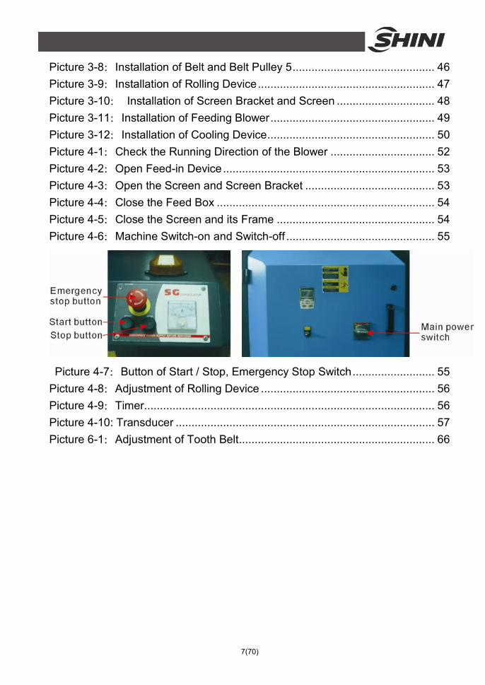
Picture 3-8:Installation of Belt and Belt Pulley 5............................................. 46
Picture 3-9:Installation of Rolling Device........................................................ 47
Picture 3-10: Installation of Screen Bracket and Screen ............................... 48
Picture 3-11:Installation of Feeding Blower.................................................... 49
Picture 3-12:Installation of Cooling Device..................................................... 50
Picture 4-1:Check the Running Direction of the Blower ................................. 52
Picture 4-2:Open Feed-in Device................................................................... 53
Picture 4-3:Open the Screen and Screen Bracket ......................................... 53
Picture 4-4:Close the Feed Box ..................................................................... 54
Picture 4-5:Close the Screen and its Frame .................................................. 54
Picture 4-6:Machine Switch-on and Switch-off ............................................... 55
Picture 4-7:Button of Start / Stop, Emergency Stop Switch.......................... 55
Picture 4-8:Adjustment of Rolling Device ....................................................... 56
Picture 4-9:Timer............................................................................................ 56
Picture 4-10: Transducer .................................................................................. 57
Picture 6-1:Adjustment of Tooth Belt.............................................................. 66

8(70)
1. General Description
Please read this manual carefully before using this machine in order to operate correctly against any damage caused due to improper operation.
Note! Always take great care when the knives are within reach, they are very sharp and can cause personal injury.
Forbidden to process flammable or toxic material!
SGF-26 series are applicable to granulating and recycling plastic films. After pressed toughly by a material scroller, films are sent to cutting chamber to be cut into granules to reuse.
Model: SGF-2690

9(70)
1.1 Coding Principle
1.2 Feature Standard configuration
1) Applicable to process extruded waste films and adopt high safety operation design.
2) Cutters with best cutting angle and adjustable V rotating blades. 3) Integrated material scrolling devices into one unit can facilitate the
granulating work by easily scrolling the material into cutting chamber. 4) Motor overload protective function. 5) React with assembly line or operated by specialized person. 6) Width adjustable feeding inlet of 900 or below and thickness adjust designs
facilitate the different film granulating applications. 7) Scrolling motor has a frequency convertor to satisfy different film cutting
capacity. 8) Cutting chamber is equipped with a cooling water loop to effectively lower the
temp.of the chamber so that improve working efficiency and avoid granule powder from melting up.
9) Equipped with cyclone dust collector, which can effectively separate regrinds and air and is also convenient for regrinds collection.
10) Adjustable range of feeding speed 5~50m/min. 11) Thickness range of material 0.2~6mm.
Accessory option
1) Special screens with different diameters (Ф6、Ф8、Ф12mm) are optional. All service work should be carried out by a person with technical training or corresponding professional experience. The manual contains instructions for both

10(70)
handling and servicing. Chapter 6, which contains service instructions intended for service engineers. Other chapters contain instructions for the daily operator.
Any modifications of the machine must be approved by SHINI in order to avoid personal injury and damage to machine. We shall not be liable for any damage caused by unauthorized change of the machine.
Our company provides excellent after-sales service. Should you have any problem during using the machine, please contact the company or the local vendor.
Headquarter and Taipei factory: Tel: (886) 2 2680 9119 Shini Plastics Technologies (Dongguan), Inc: Tel: (86) 769 8111 6600 Shini Plastics Technologies India Pvt.Ltd.: Tel: (91) 250 3021 166

11(70)
1.3 Technical Specifications 1.3.1 Technical Specifications
Table 1-1:Technical Specifications Model SGF-2660 SGF-2690
Motor Power (kW, 50 / 60Hz) 7.5 / 8.3 15 / 17.3 Rotating Speed (rpm, 50/60Hz) 410 / 492 410 / 492 Scrolling Power (kW, 50 / 60Hz) 0.75 0.75 Conveying Blower Power (kW, 50 / 60Hz) 0.75 / 0.83 1.1 / 1.3 Scrolling Speed (rpm) * * Knife Materia SKD11 SKD11 Number of Fixed Blades 3×2 3×2 Number of Rotating Blades 3×2 3×2 Maximum Granulating Capacity (kg / h) 200 300 Noise Level dB (Max.) 90~95 90~95 Cooling Loop Dia. of Screen Mesh Ф10 Ф10 Special Screens Dimensions H (mm) 1270 1270 H1 (mm) 1860 1860 W (mm) 1610 1910 W1 (mm) 600 900 D (mm) 1410 1410 Weight (kg) 1150 1507
Note: 1) "√" Stands for standard, "○" stands for options. 2) "*" stands for different speed according to the thickness of the film. 3) SKD11 is material code number of Japanese JIS standard. 4) Max. capacity of the machine is subject to diameter of screen hole and composition of the material.
The listed maximum output is tested continually with PET films, with 1mm thickness size. 5) Noise level will vary with different materials and motor types. 6) Cooling water flange dia.: Φ16mm. 7) For avoiding plastic to adhibit the blade, all materials should be crushed at normal temperature. 8) Power supply: 3Φ, 230 / 400 / 460 / 575VAC, 50 / 60Hz.

12(70)
1.3.2 Dimensions
Picture 1-1:Dimensions (Standard)

13(70)
1.4 Safety Regulations Follow the instructions in this manual to avoid personal injury and damage to machine components. The following safety measures shall be followed when operating the granulator.
1.4.1 Safety Signs and Labels
Electrical installation must only be done by a competent electrician!
Before the granulator is opened for servicing and maintenance, always disconnect the power with both the main switch and the control switch on the granulator.
Never put any part of your body through the granulator openings, unless both the main switch and the control switch on the granulator are in "Off" position.
High voltage! Danger! This sign is attached on the control box and the wiring box.
Be careful with the rotating knives, they are very sharp and can cause personal injury!
The granulator should not be able to start before the hopper and screen bracket are properly closed.
Attention please! Ear protection is used during granulating of plastic materials.
Regularly clean dust in air from air inlet.
Make sure the power has been cut off before opening the feed box.

14(70)
Loading blower is applicable to convey regrind powder and it requires the temperature less than 80℃.
The loading blower has great suction power and it is easy to get goods or clothes sucked into, so it should have a protective cover.
Danger! Do not use damaged or parts that lack frequency converter, because there is a risk of being hurt.
Caution! Do not let any wire lead or screw fall into the frequency converter or it will damage the frequency converter.
When operate the granulator, please notice the following signs
Hazard High voltage! May lead to casualty or other serious danger. Please cut off the power before repairing. Circuit diagram should only be changed by professionals. Grounding is necessary
Warning Pinch risk when moving belt. Take out or open protective cover is not allowed when it is running.
Warning There is a pinch risk for this protective cover keep some distance away from that.

15(70)
Warning The cutter is very sharp, can cause injury. It is not allowed to take out or open protective cover when it is running. Keep some distance away from the cutters.
Notice Read the instruction manual carefully before operating Before start, do the test of safety device according to the instruction. It is not allowed to change the design of the machine unless it is approved from the manufacture.
Water outlet: drainage outlet.
Water inlet: inlet for replenishing water and cooling water.
1.4.2 Transportation and Storage of the Machine
Transportation
1) SGF-26 series of granulators are packed in plywood cases with wooden pallet at the bottom, suitable for quick positioning by fork lift.
3) Do not rotate the machine and avoid collision with other objects during transportation to prevent improper functioning.
4) The structure of the machine is well-balanced, although it should also be handled with care when lifting the machine for fear of falling down.
5) The machine and its attached parts can be kept at a temperature from -25 ℃
to +55 for long distance transportation and for a short distance, it can be ℃
transported with temperature under +70 .℃

16(70)
Storage
1) SGF-26 series should be stored indoors with temperature kept from 5 to ℃
40 and humidity below 80%.℃ 2) Disconnect all power supply and turn off main switch and exigency stop
switch. 3) Keep the whole machine, especially the electrical components away from
water to avoid potential troubles caused by the water. 4) Use plastic film to cover the machine tightly to prevent the machine from dust
and rains.
Working environment
The machine should be operated: 1) Indoors in a dry environment with max. temperature +45 and humidity no ℃
more than 80%. Do not use the machine:
1) If it is with a damaged cord. 2) On a wet floor or when it is exposed to rain to avoid electric shock. 3) If it has been dropped or damaged until it is checked or fixed by a
qualified serviceman. 4) This equipment works normally in the environment with altitude over
3000m. 5) At least 1m surrounding space is requested when this equipment is
running. Keep this equipment away from flammable sources at least two meters.
6) In the work area of vibration and strong magnetic force.
Rejected parts disposal When the equipment has run out its life time and can not be used any more, unplug the power supply and dispose of it properly according to local code.
Fire Hazard! In case of fire, CO2 dry powder fire extinguisher should be applied.

17(70)
Flammable materials or materials which are contaminated by flammable substances/liquid may not be processed in the granulator. Serious risk of fire or explosion may cause personnel injury.
It is very important to tighten the screw as required torque.
When material’s width is larger than feed port’s, please cut it off until the length is shorter than feed port’s.
Please don’t put materials into the granulator if they are thinner than 0.5mm and are soft and flexible, like rubber.
The thickness range of grinding material is 0.2~6mm. 1.5 Exemption Clause
The following statements clarify the responsibilities and regulations born by any buyer or user who purchases products and accessories from Shini (including employees and agents). Shini is exempted from liability for any costs, fees, claims and losses caused by reasons below:
1. Any careless or man-made installations, operation and maintenances upon machines without referring to the Manual prior to machine using.
2. Any incidents beyond human reasonable controls, which include man-made vicious or deliberate damages or abnormal power, and machine faults caused by irresistible natural disasters including fire, flood, storm and earthquake.
3. Any operational actions that are not authorized by Shini upon machine, including adding or replacing accessories, dismantling, delivering or repairing.
4. Employing consumables or oil media that are not appointed by Shini.

18(70)
2. Structural Features and Working Principle 2.1 General Description
Surplus material granulator of SGF-26 series is suitable to granulate many kinds of plastic film surplus. The granulator is controlled by main power switch, safety switch, the switch of "start/stop" and emergency stop switch. The film surplus is sent by the feed mechanism to the pressing device to press it firm, and then transferred to the cutting assembly, cutting it into grain type.
2.1.1 Working Principle
Parts name:
A. Convey device B. Feeding box C. Cutting chamber
D. Screen bracket E. Extraction line
Picture 2-1:Working Principle
Through the feed throat (B), the film surplus is pressed firmly by the driving wheel (C) and driven wheel (A) and then sent to the cutting chamber. In the chamber, the surplus is granulated into grains by the rotary blade (D) and static blade (E). The granulated grains are fallen into the storage box (G) through the screen (F). The storage box, screen and its frame can be removed. The feed box can be opened to allow cleaning and easier maintenance.

19(70)
Film material is conveyed to feeding box B by the convey device A on feeding box. Then it enters into cutting chamber C where the film material is granulated by the relative rotation between rotary blade and static blade. Size of the granulated grains depends on size of diameter sieve on screen bracket D. The granulated grains are fallen into the storage box D (integrated structure of diameter sieve and storage box) and then conveyed by extraction line E. There is
a feeding blower outside to take the granulated grains into cyclone separator to separate granulated grains and air.
2.2 Safety System To avoid accidental bodily injury during granulator running, a set of safety system has been designed. High-speed rotating cutter is located in the granulator and subject to accident. So safety system has been set up to protect bodily safety. In any cases, the safety system cannot be changed at random. Otherwise the machine will be under dangerous condition and subject to accident happening. The maintenance and preservation of safety system shall be done by professional staff. In case the safety system of granulator is changed, our company will not perform our commitment. The replacement of all spare parts will be done by SHINI company.
2.2.1 Emergency Stop Switch
There is one red button on the control panel. Upon pushing it, the machine will stop running (use in emergency circumstances). Turn the button in the arrow direction as shown on the button, the button will reset (counter-clockwise).

20(70)
Picture 2-2:Emergency Stop Switch
2.2.2 Safety Switch
There is a safety switch of independent operating parts on granulator. Change of safety switch’s position will make the operating parts separate from the safety switch, which will cut off the power supply. There are two safety switches on the granulator: one is located behind the front left door while the other one is in front of the back left door.
Picture 2-3:Safety Switch
2.2.3 Lock
The lock of feed box, screen bracket and storage box is a long hexagonal screw, when opening the door, this hexagonal screw shall be loosened. The loosening will last a quite long period of time to enable the granulator fully stops, avoiding personnel injury.
The screen bracket is locked by bolts. It’s necessary to loosen the bolts when opening the screen bracket. The loosening will last a quite long period of time, which is long enough to make the granulator completely stops, and thus to avoid personal injury. Besides, an adjustable spring bolt is installed, which can avoid personal injury caused by the rushing down of screen bracket after the bolts are all took off.
前左门安全开关 后左门安全开关
Front left door safety switch Back left door
safety switch

21(70)
Picture 2-4:Hexagonal Handle
Befroe starting up, check if the screen bracket and front block have been tightened.

22(70)
2.3 Assembly Drawing 2.3.1 Assembly Drawing
Note: Please refer to 2.3.2 material list about the parts code.
Picture 2-5:Assembly Drawing

23(70)
2.3.2 Parts List
Table 2-1:Parts List
SGF-2660 SGF-2690 No. Name Part No. Quantity Part No. Quantity
1 Rack assembly - 1 - 1
2 Screen bracket assembly - 1 - 1
3 Cutting chamber assembly - 1 - 1
4 Feed box assembly - 1 - 1
5 Shield assembly - 1 - 1
6 Screen bracket confine board
- 1 - 1
7 Hexagonal head bolt M6x20 YW60062000100 4 YW60062000100 4
8 Hexagonal nut M6 YW64000600000 4 YW64000600000 4
9 Flat gasket 6 YW66061200000 4 YW66061200000 4
10 Drive assembly - 1 - 1
11 Suspending span cover - 1 - 1
12 Inner hexagon column screw M8x20
YW61082000000 4 YW61082000000 4
13 Flat gasket 8 YW66081600000 4 YW66081600000 4
14 Automatically feeding assembly
- 1 - 1
15 Electronic handspike assembly
- 1 - 1
* means possible broken parts. ** means easy broken part. and spare backup is suggested. Please confirm the version of manual before placing the purchase order to guarantee that the item number of the spare part is in accordance with the real object.

24(70)
2.3.3 Cutting Chamber
Picture 2-6:Cutting Chamber
2.3.4 Cutting Chamber Parts List
Table 2-2:Cutting Chamber Parts List SGF-2660 SGF-2690
No. Name Part No. Quantity Part
No. Quantity
1 Right block - 1 - 1
2 Back block - 1 - 1
3 Material fending press plate - 2 - 2
4 Left block - 1 - 1
5 Bearing block - 2 - 2
6 Bearing cover - 2 - 2
7 Front block - 1 - 1
8 Front pressing block - 2 - 2
9 Fixed blade - 6 - 6
10 Back pressing block - 2 - 2
11 Material fender - 2 - 2
25(70)
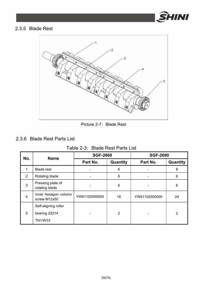
2.3.5 Blade Rest
Picture 2-7:Blade Rest
2.3.6 Blade Rest Parts List
Table 2-3:Blade Rest Parts List SGF-2660 SGF-2690
No. Name Part No. Quantity Part No. Quantity
1 Blade rest - 6 - 8
2 Rotating blade - 6 - 6
3 Pressing plate of rotating blade
- 6 - 6
4 Inner hexagon column screw M12x50
YW61102500000 18 YW61102500000 24
5
Self-aligning roller
bearing 22214
TN1/W33
- 2 - 2

26(70)
2.3.7 Transmission Parts
Picture 2-8:Transmission Parts
2.3.8 Transmission Parts List
Table 2-4:Transmission Parts List SGF-2660 SGF-2690
No. Name Part No. Quantity Part No. Quantity
1 Taper sleeve - 1 - 1
2 Motor belt pulley - 1 - 1
3 motor - 1 - 1
4 Triangle belt - 1 - 1
5 Big belt pulley - 1 - 1

27(70)
2.3.9 Screen and Its Frame
Picture 2-9:Screen and Its Frame
2.3.10 Screen and Its Bracket Parts List
Table 2-5:Screen and Its Bracket Parts List SGF-2660 SGF-2690
No. Name Part No. Quantity Part No. Quantity
1 Screen - 1 - 1
2 Assembly of screen bracket - 1 - 1
3 Screen bracket shaft cover - 2 - 3
4 Screen bracket shaft - 1 - 1
5 Air inlet flange - 1 - 1
28(70)
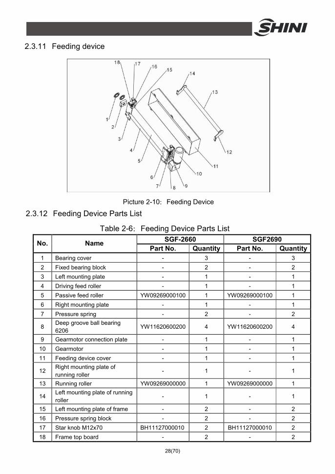
2.3.11 Feeding device
Picture 2-10:Feeding Device
2.3.12 Feeding Device Parts List
Table 2-6:Feeding Device Parts List SGF-2660 SGF2690 No. Name
Part No. Quantity Part No. Quantity 1 Bearing cover - 3 - 3 2 Fixed bearing block - 2 - 2 3 Left mounting plate - 1 - 1 4 Driving feed roller - 1 - 1 5 Passive feed roller YW09269000100 1 YW09269000100 1 6 Right mounting plate - 1 - 1 7 Pressure spring - 2 - 2
8 Deep groove ball bearing 6206
YW11620600200 4 YW11620600200 4
9 Gearmotor connection plate - 1 - 1 10 Gearmotor - 1 - 1 11 Feeding device cover - 1 - 1
12 Right mounting plate of running roller
- 1 - 1
13 Running roller YW09269000000 1 YW09269000000 1
14 Left mounting plate of running roller
- 1 - 1
15 Left mounting plate of frame - 2 - 2 16 Pressure spring block - 2 - 2 17 Star knob M12x70 BH11127000010 2 BH11127000010 2 18 Frame top board - 2 - 2

29(70)
2.4 Wiring Diagram 2.4.1 SGF-2690 Circuit Diagram (400V)
2.4.1.1 SGF-2690 Main Ccuit Diagram (400V)
Picture 2-11:SGF-2690 Main Ccuit Diagram (400V)

30(70)
2.4.1.2 SGF-2690 Control Wiring Diagram (400V)
Picture 2-12:SGF-2690 Control Wiring Diagram 1 (400V)
31(70)
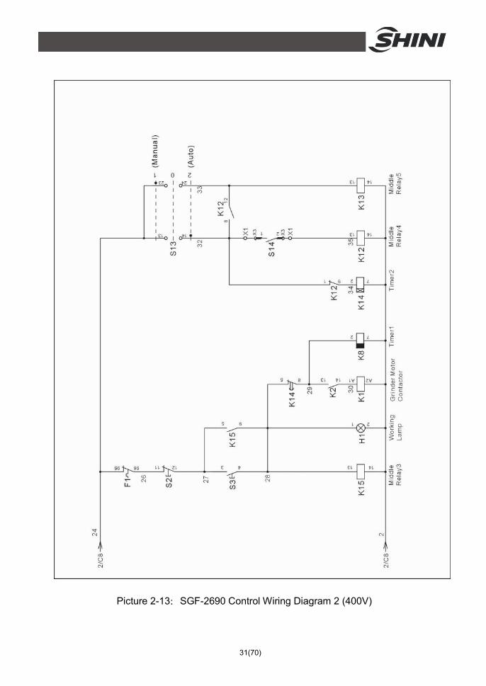
Picture 2-13:SGF-2690 Control Wiring Diagram 2 (400V)

32(70)
Picture 2-14:SGF-2690 Control Wiring Diagram 3 (400V)
33(70)
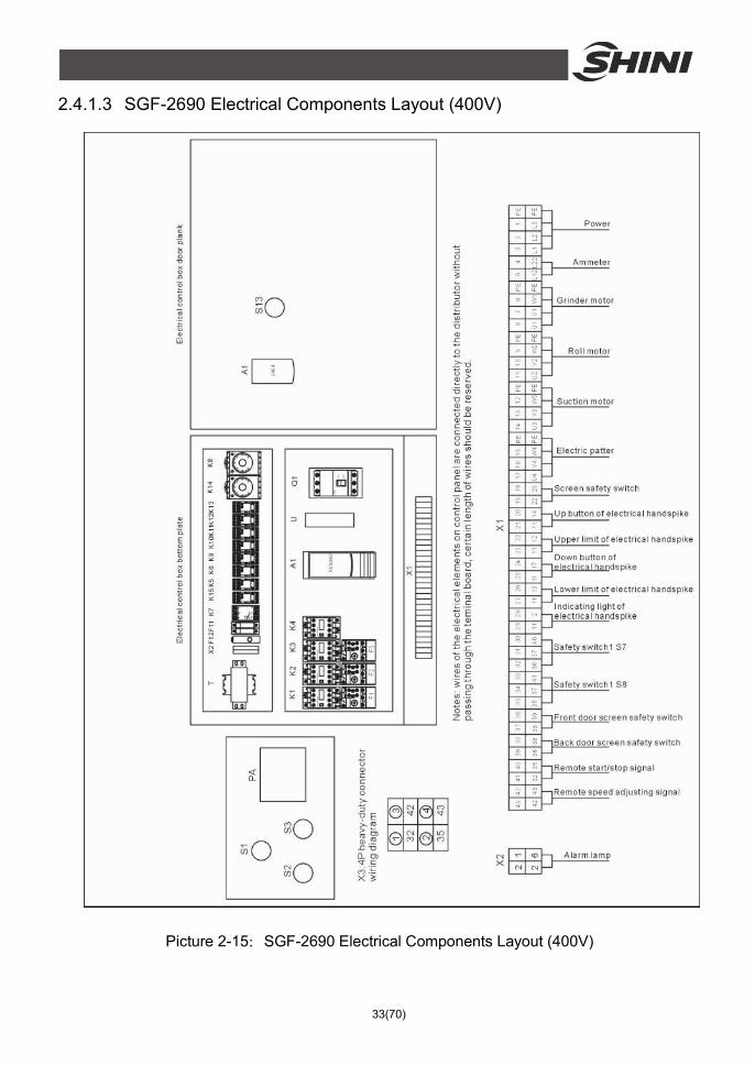
2.4.1.3 SGF-2690 Electrical Components Layout (400V)
Picture 2-15:SGF-2690 Electrical Components Layout (400V)

34(70)
2.4.2 SGF-2690 Electrical Components List (400V)
Table 2-7:SGF-2690 Electrical Components List (400V)
No. Symbol Name Specification Part No.
1 Q1 Gate circuit breakers* 60A YE41106000000
2 Q2 Contactor* 230V 50/60Hz YE00341100000
3 - Auxiliary contact terminal 230V 50/60Hz YE00401000200
4 K2 Contactor* 230V 50/60Hz YE00301000000
5 K3 K4 Contactor* 230V 50/60Hz YE00300100000
6 K5 K6 K9 Middle relay 24VDC YE03272400000
7 K7 Phase disorder protector 400V 50/60Hz YE03103800000
8 K8 Timer relay 230V 50/60Hz YE86322000000
9 K14 Timer relay 3S~60M 230VAC YE86300300000
10 K10~K13 K15 Middle relay 220VAC YE03270700000
11 F1 Overload relay 25~36A YE01253600100
12 F2 Overload relay 2~3.2A YE01023200000
13 F3 Overload relay 0.63~1A YE01063100000
14 F11 Fuse box** 2P YE41032200000
15 - Fuse** 1A YE46001000100
16 F12 Fuse** 2A YE41001000000
17 A1 Fequency changer 400V 0.75kW YE75350300000
18 - Controller pad - YE81040400000
19 T Transformer 500mA YE70402300800
20 S1 Emergency stop button 400VAC YE11320300000
21 S2 S11 S12 Button 400VAC YE11375800000
22 S3 H1 Start button 400VAC YE11325300000
23 S4~S6 Safety switch AC-15 YE16147600100
24 S7 S8 Sensor 24VDC NPN -
25 H2 Indicate lamp 230VAC YE83052300200
26 H3 Alarmindicate lamp 230VAC YE83305100200
27 S13 Selector switches Ui=300V Ith=5A YE12102000000
28 U DC power OUT=24VDC 1.5A YE71352400000
29 M1 Motor 400V 50Hz 15kW -
30 M2 Motor 400V 50Hz 0.75kW -
31 M3 Motor 400V 50Hz 1.1kW -
32 M4 Motor 400V 50Hz 0.18kW -
33 PA Galvanometry 50A YE25675000000

35(70)
No. Symbol Name Specification Part No.
34 X1 Terminal board 76A YE61100000000
35 - Terminal board - YE61103500000
36 - Terminal board 57A YE61060000000
37 - Terminal board - YE61063500000
38 - Terminal board 32A YE61250040000
39 - Terminal board - YE61253500000
40 X2 Terminal board 32A YE61250040000
41 X3 Heavy duty connector 4P 10A YE68041000200
* means possible broken parts. ** means easy broken part. and spare backup is suggested. Please confirm the version of manual before placing the purchase order to guarantee that the item number of the spare part is in accordance with the real object.

36(70)
2.5 Electrical Components Instruction
Picture 2-16:Electrical Components Instruction 1. Frequency converter, which controls the rotating speed of the scrolling motor. 2. Transformer, provide suitable voltage for the control circuit. 3. Timer, which can setup the suction blower's delay time. 4. Thermo overload relay, which can protect the motor and suction blower when
they are overloading or phase opening. 5. Contactor, which connects or disconnects the main circuit. 6. Circuit breaker, which perform the function of short circuit protection or circuit
isolation.
37(70)
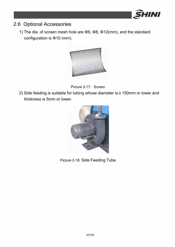
2.6 Optional Accessories 1) The dia. of screen mesh hole are Φ6, Φ8, Φ12(mm), and the standard
configuration is Φ10 (mm).
Picture 2-17:Screen
2) Side feeding is suitable for tubing whose diameter isφ150mm or lower and thickness is 5mm or lower.
Picture 2-18: Side Feeding Tube

38(70)
3) DS-26 Dust separate System
Picture 2-28:Installation of Dust Separating System
2.6.1.1 Outline Dimensions
Cyclone dust collector (Ф×h)……………………………… 600×1030mm
Dust collecting device (l×w×h) ……………………………… 920×500×2610mm
Name Quantity Notes
Cyclone dust collector 1 -
Dust separator 1 -
Air blower with bracket 1 -
Stainless steel pipe (long) 1 -
Pipe bunch 5 6 -
Cloth bag (two ends) 1 with cotton string
Filtering bag 1 -
Dust collecting bag 2 with cotton string
Fixing legs of cyclone bracket 3 on top, 3 at bottom
-
Cloth bag bracket 1 -
Steel wired plastic pipe 4"×3m 3 -
Locking bar 2 -

39(70)
2.6.1.2 Installation of Dust Separating System
Read through chapter 3 before operation. The connection of dust separating system’s circuit should be carried out by a professional electrician.
Before first startup:
Parts of no paint are coated with anti-rust oil before leaving plant. The anti-rust oil should be cleaned off before operation.
Connection
1) Install a separator whose diameter is Ф250mm under the cyclone dust collector.
2) Connect convey pipe whose diameter is 4"×2. 3) Install dust collecting device, including air and dust collecting bag. 4) Put a container under separator to collect plastics which just go through
dedusting.
Connect the separator with a cloth bag to guarantee ventilation of cloth bag.
2.6.1.3 Operation and Maintenance of Dust Separating System
Daily check
Air bag and dust bag: Check whether the air bag or dust bag is damaged. If there is any damage, please replace it. Convey pipe: Check whether the convey pipe is damaged. If there is any damage, please replace it. Check whether the connection is good and seal it up. Check whether the dust bag is full. Please empty it if it’s full.

40(70)
Storage box: Check whether the storage box is right under the dust separator. If it’s not, please adjust it. Check the storage box. If it’s full, please take away in time the plastics which has gone through dedusting. Weekly check
Check whether the wires are damaged and the connection situation. If there is any damage, please fix it.
2.6.1.4 Clean of Dust Separating System
Clean it once after replace the plastics or 300h of operation. Before cleaning, please turn off the power supply. 1) Clean the inner wall of device first. 2) Check and clean the dust separator when necessary. 3) Move away the separator and use high pressure air to blow off inside
grains. 4) Empty the storage box and clean its inside. 5) Shake the air bag to make the dust fall off. 6) Install all the parts back to the machine.

41(70)
3. Installation and Debugging
Read through this chapter before installation.
Install as following orders to avoid any accident!
Be careful! Not to be cut by the sharp blade.
Power connection must be done by the professional electrician to avoid electrical shock.
Caution!
Cutters should be laid level,prevent the cutters from self-rotating when do installation, don't let your hands be near to the cutters to avoid personal injury.
Notice!
Do not install the cutters by working together, because this could bring personal injury. Use a thick wood block to stop the rotating knives from turning.
Notice! The blades are very sharp, so use protective gloves to avoid being cut. Notice! Please use new screws and gaskets when installing cutters.
The power connection of the granulator should be carried out by professional electrician so to avoid electrical shock!
42(70)
3.1 Installation Notice 1) Make sure voltage and frequency of the power source comply with those
indicated on the manufacture's plate, which is attached to the machine. 2) Power cable and earth connections should conform with local regulations. 3) Use independent power cable and ON/OFF switch. The cable's size should
not smaller than those applied in the control box. 4) The power cable connection terminals should be tightened securely. 5) The machine requires a 3-phase 4-wire power source, connect the power
lead (L1, L2, L3) to the live wires, and the earth (PE) to the ground. 6) Power supply requirements:
Main power voltage: +/- 10% Main power frequency: +/- 2%
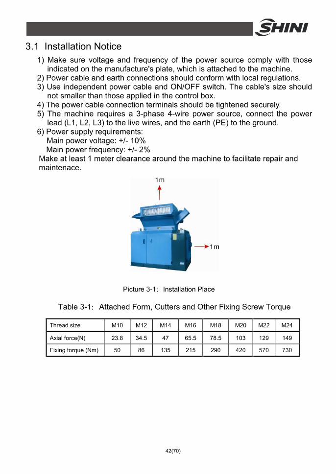
Make at least 1 meter clearance around the machine to facilitate repair and maintenace.
Picture 3-1:Installation Place
Table 3-1:Attached Form, Cutters and Other Fixing Screw Torque
Thread size M10 M12 M14 M16 M18 M20 M22 M24
Axial force(N) 23.8 34.5 47 65.5 78.5 103 129 149
Fixing torque (Nm) 50 86 135 215 290 420 570 730

43(70)
3.2 Installation Place Move the granulator to the proper placeand fix its castors
Check and make sure the installation ground is level, there is enough intensity when it is running.
3.3 Installation of Bearing and Blade Rest 1) Install the sealled 2 and greased bearing 1 into the bearing base 3 in
sequence.
Picture 3-2:Installation of Bearing and Blade Rest
2) Install the bearing base with bearing, flap and bearing on the blade shelf. 3) Put the blade rest in the cutting chamber to enable two ends of bearing
pedestal match the holes at both sides and then tighten the screw. 4) Install the bearing cover and tighten it by screw.
Note! Apply grease on the bearing and bearing pedestal.
3.4 Installation of Rotary Blade and Static Blade Steps of installation
1) Put the rotary blade into the groove of blade rest; its hole position shall match with the fixing hole position of blade rest. Then press the pressing blade and screw down the screws as well as the spring gasket until the blade doesn't shake (for easier adjustment of the clearance between rotary blade and static blade).
2) Install the front and back pressing blocks and fixed blade on front and back blocks. Screw down the screws until the blade doesn't shake.
3) Use filler gauge to test the clearance between fixed blade and rotary blade. The normal clearance is 0.1~0.15mm. If not within this scope, adjust fixed blade and rotary blade to reach the scope and then screw down their screws.

44(70)
them.
Picture 3-3:Installation of Rotary Blade and Static Blade
Note! When adjusting the clearance, it shall not be too small to avoid damage to the cutter!
Note! To avoid personal injury and machine damage, the fixing screw of blades shall be tightened well.
3.5 Installation of Belt and Belt Pulley 1) Put the key into keyway of shaft and then install the big belt pulley.
Picture 3-4:Installation of Belt and Belt Pulley 1 2) Put the lock ring into the round hole of big belt pulley to make its hole position
match with the big belt pulley and then tighten the inner hexagon screw.
3) Use dial indicator to adjust big belt pulley’s balance: Put the dial indicator tightly against the big belt pulley and then turn the big belt pulley to see whether the needle of the dial indicator points at the range within 0~0.1mm.

45(70)
Picture 3-5:Installation of Belt and Belt Pulley 2
4) Tighten 8 inner hexagon screws on lock ring after balancing.
5) Put the small belt pulley on the shaft of motor and tighten 6 inner hexagon screws.
6) Put the motor on motor fixing board. Then push it forward to shorten the
distance between the big and small belt pulley while adjusting and tightening 4 fixing screws.
Picture 3-6:Installation of Belt and Belt Pulley 3 7) Adjust the big and small belt pulley to be parallel and level: Put level ruler
between the big and small belt pulley. See whether the mercury is in the middle. If it’s not, then adjust the small belt pulley (note: It’s not allowed to adjust the big one) to make the small belt pulley level with the big one.

46(70)
Picture 3-7:Installation of Belt and Belt Pulley 4
8) Put the belt on and push the motor to the right as well as tighten the positioning screw to make the 4 belts bear stress evenly and pull the belts tight. Then tighten the positioning screws.
Picture 3-8:Installation of Belt and Belt Pulley 5
3.6 Installation of Convey Device
1) Put the driving feed roller 3 into fixed bearing block 7. Then install the bearing on bearing block and connect it with screws to the right mounting plate1, left mounting plate 4 and left side plate of frame 6
2) Put the driven feed roller 2 into sliding bearing block 5 and install the bearing
on bearing block. Then install them along the bearing block, left and right mounting plate and sliding groove on left side plate of frame
3) Put the pressure spring on the sliding bearing block 5 and then install the
pressure spring block 9. Next, install the top board 8 of frame and fixing it by using screws.
4) After sealing the bearing block cover, use screws to connect the holes on
right and left mounting plates to the feed box’s back. 5) Install the gearmotor connection plate 10 and use screws to fix it on the right
mounting plate and left side plate of frame. Then install gearmotor 11 and use screws to fix it on the gearmotor connection plate 10.
6) Use screws to fix left mounting plate 13 of guide roller and right mounting
plate 15 of guide roller on the feeding device shield 12.
7) Use screws to fix guide roller 14 on the right and left mounting plate of guide rollers.

47(70)
8) Use screws to fix convey device shield to the feed box’s back.
Picture 3-9:Installation of Rolling Device

48(70)
3.7 Installation of Screen Bracket and Screen 1) Put the screen bracket under the cutting chamber. Move the screen bracket
to the arc of hinge pin hole seat and match the screen shaft with the hinge pin hole seat. Then install the pressing plate of hinge pin hole seat and tighten them by screws.
2) Fold downward the screen bracket and install the screen into it.
3) Raise the screen bracket. Shut down the spring bolt and lock the screw right
ahead.
Note! The screw must be tightly locked in this step. Otherwise, it will cause distortion of screen bracket and broken of screws.
Picture 3-10: Installation of Screen Bracket and Screen
3.8 Installation of Feeding Blower 1) Install the blower 1 on the blower fixing plate 2 of granulator rack and tighten
fixing screw 3. 2) Insert feeding blower 1 and feed-in pipe 5 into extraction line 4 of granulator.

49(70)
3) Connect the power wire according to the circuit diagram.
Picture 3-11:Installation of Feeding Blower
Warning! When the material feed blower is rotating in wrong direction, its working capability will decrease by no less than 25%! Please cut off the power supply, exchange two lines among three lines of the fan in the control cabinet.
First close the main power switch before the power supply of blower is connected; otherwise, risk of electric shock may be encountered!
3.9 Installation of Cooling Device Connect the cooling water pipe to the cooling water access.

50(70)
Picture 3-12:Installation of Cooling Device

51(70)
4. Operation Guide 4.1 Startup Pretest
Unpainted part of the machine has been covered with stainless oil. Before use, the stainless oil should be cleaned.
1) Clean with a towel. 2) Wash with a towel dipping with amyl acetate.
4.1.1 Before the First Startup
1) Check whether the granulator is in the level state. 2) Check the space of the cutting tools to see whether the lockup screws of the
blades are tightened. 4.1.2 After First Startup for 2 Hours
1) Check the space of the cutting tools of the fixed blades and rotating blades again; check whether the lockup screws of the blades are loose.
2) Check the position-adjusting screws of the motor and check whether the position-adjusting screws are tightened.
4.1.3 After First Startup for 20~30 Hours
Check and adjust the belt's tensility after a 20~30 hour full-load operation.
4.2 Circuit Connection The installation of the granulator's circuit must be conducted by the professional electricians. 1) Connect granulator to the power. 2) Connect the transmission belt clockWise.
4.2.1 Check the Running Direction of the Motor
1) Open the door to check whether the feed box is closed. 2) Ensure the main power switch is in ON position. 3) Check the emergency stop. 4) Start the granulator via pressing the START button and stop the granulator
via pressing the STOP button. 5) The granulator needs some time to fully come to a halt, After full stop, check
whether the running direction is clockWise.
52(70)
CAUTION! The cutting tools may be damaged and the granulating capability will be reduced if there is a wrong running direction. Please disconnect the power and transpose any two wires of the three in the main power.
4.2.2 Check the Running Direction of the Blower.
1) Check whether the running direction of the blower is in accordance with the symbol on the shield.
2) Connect to the power and stop again to check the blower's running direction.
Picture 4-1:Check the Running Direction of the Blower
CAUTION! If the blower's running direction is not in accordance with the symbol, the machine's working capability will be reduced by at least 25 percent. Under these circumstances, please disconnect to the main power and transpose any two wires of the three in the blower.
4.3 Opening the Feed Box
Note! Prior to opening the feed box and the storage box, cut off the main switch and the power supply on the granulator.
Caution! The blade is very sharp-edged and easy to injure people.
4.3.1 Opening the Feed Box
1) Check if the feed box is empty and then cut off the main power.

53(70)
2) Loosen the long star screw 1 and open the front and back door. Open the feed box through electronic handspike controller 2 on back left door.
3) With its self-locking function, electronic handspike can prevent feeding device drop out.
Note! The feed box is very heavy. When opening or closing it, be careful of its sudden falling to cause bodily injury!
Picture 4-2:Open Feed-in Device
4.3.2 Open the Screen and Screen Bracket
1) Turn off power supply of granulator 2) Loosen locking screw 2. 3) Loosen spring bolt 1. 4) Hold screen bracket handle 3 with hands and put the screen bracket down
slowly. 5)Take out the screen.
Picture 4-3:Open the Screen and Screen Bracket 4.4 Closing Feed Box and Screen Bracket 4.4.1 Closing the Feed Box
1) Make sure no powder remains on the Interface surface or corner. 2) Make sure all the doors open and close the feed box by operating electric
54(70)
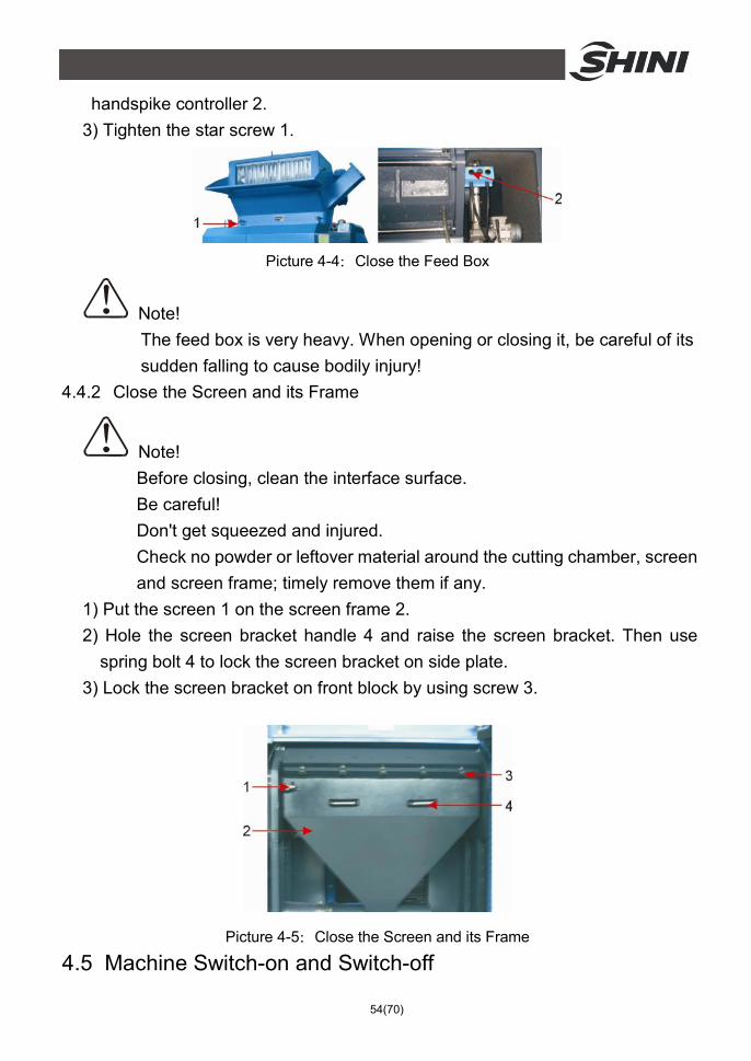
handspike controller 2. 3) Tighten the star screw 1.
Picture 4-4:Close the Feed Box
Note! The feed box is very heavy. When opening or closing it, be careful of its sudden falling to cause bodily injury!
4.4.2 Close the Screen and its Frame
Note! Before closing, clean the interface surface. Be careful! Don't get squeezed and injured. Check no powder or leftover material around the cutting chamber, screen and screen frame; timely remove them if any.
1) Put the screen 1 on the screen frame 2. 2) Hole the screen bracket handle 4 and raise the screen bracket. Then use
spring bolt 4 to lock the screen bracket on side plate. 3) Lock the screen bracket on front block by using screw 3.
Picture 4-5:Close the Screen and its Frame
4.5 Machine Switch-on and Switch-off

55(70)
The granulator is controlled by the main power switch, safety switch, button of "start/stop" and emergency stop switch. The main power switch of granulator is installed on the front panel. Turning of this switch is made to control switch on or switch off the machine.
Picture 4-6:Machine Switch-on and Switch-off
Button of "start/stop"
The granulator is equipped with the button of "start/stop" to control the operations of "start"and "stop".
Emergency stop switch:
In addition, the machine is also designed to have an emergency stop switch used in such cases that any accident occurs or urgent stop is needed.
Picture 4-7:Button of Start / Stop, Emergency Stop Switch
Note! The machine cannot stop until the material in the feed box and the cutting chamber has been totally granulated. Otherwise, the left material may block the rotor and the machine may trip due to motor overload when it restarts.
4.6 Adjustment of feeding Device

56(70)
The feeding device of granulator can adjust the clearance between the driving wheel 1 and the driven wheel 2 according to the thickness of surplus materials to be granulated.
Rotate the hexagonal screw handles 3 at both sides at the same time; press the pressure head 4 and compression spring 5 to enable the bearing pedestal of the driven wheel slides in the guide slot for the purpose of adjusting the clearance with the driving wheel.
Picture 4-8:Adjustment of Rolling Device
Note! Keep the same clearances at both side between the driven wheel and the driving wheel. Otherwise the rolled material is not pressed under balance to impact the cutting capability.
4.7 Timer (With Material Feed Blower) When the granulator is shutdown, the timer can extend the working time of the material feed blower to send all granulated material out of the storage box. The set time of the timer varies from the diameter of screen hole and granulating capability.
Picture 4-9:Timer

57(70)
4.8 Transducer
Picture 4-10: Transducer
58(70)
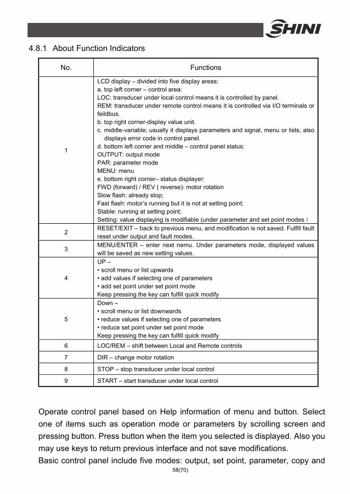
4.8.1 About Function Indicators
No. Functions
1
LCD display – divided into five display areas: a. top left corner – control area: LOC: transducer under local control means it is controlled by panel. REM: transducer under remote control means it is controlled via I/O terminals or feildbus. b. top right corner-display value unit. c. middle-variable; usually it displays parameters and signal, menu or lists, also
displays error code in control panel. d. bottom left corner and middle – control panel status: OUTPUT: output mode PAR: parameter mode MENU: menu e. bottom right corner– status displayer: FWD (forward) / REV ( reverse): motor rotation Slow flash: already stop; Fast flash: motor’s running but it is not at setting point; Stable: running at setting point; Setting: value displaying is modifiable (under parameter and set point modes)
2 RESET/EXIT – back to previous menu, and modification is not saved. Fulfill fault reset under output and fault modes.
3 MENU/ENTER – enter next nemu. Under parameters mode, displayed values will be saved as new setting values.
4
UP – • scroll menu or list upwards • add values if selecting one of parameters • add set point under set point mode Keep pressing the key can fulfill quick modify
5
Down – • scroll menu or list downwards • reduce values if selecting one of parameters • reduce set point under set point mode Keep pressing the key can fulfill quick modify
6 LOC/REM – shift between Local and Remote controls
7 DIR – change motor rotation
8 STOP – stop transducer under local control
9 START – start transducer under local control
Operate control panel based on Help information of menu and button. Select one of items such as operation mode or parameters by scrolling screen and pressing button. Press button when the item you selected is displayed. Also you may use keys to return previous interface and not save modifications. Basic control panel include five modes: output, set point, parameter, copy and
59(70)
fault. If fault takes place and alarm sounds, control panel shifts into fault mode automatically and display fault codes. Under output or fault mode, users can reset faults and alarms. After connecting power supply, control panel enters output mode, where users can launch, stop, commutate and shift between local and remote controls, also users can monitor up to three actual values. For other operations, users need to enter menu and select modes.
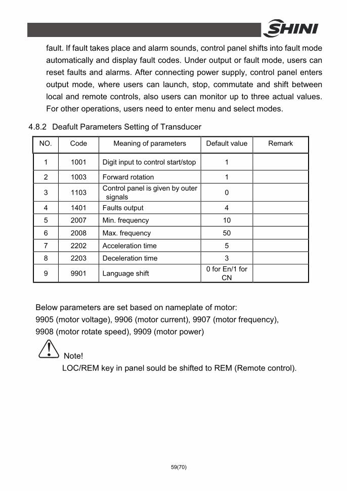
4.8.2 Deafult Parameters Setting of Transducer
NO. Code Meaning of parameters Default value Remark
1 1001 Digit input to control start/stop 1
2 1003 Forward rotation 1
3 1103 Control panel is given by outer signals 0
4 1401 Faults output 4
5 2007 Min. frequency 10
6 2008 Max. frequency 50
7 2202 Acceleration time 5
8 2203 Deceleration time 3
9 9901 Language shift 0 for En/1 for CN
Below parameters are set based on nameplate of motor: 9905 (motor voltage), 9906 (motor current), 9907 (motor frequency), 9908 (motor rotate speed), 9909 (motor power)
Note! LOC/REM key in panel sould be shifted to REM (Remote control).

60(70)
5. Trouble-shooting 5.1 Granulator Can Not Work
1) Check if the emergency stop has not been reset. If not, rotate the button anti-clockWise to reset it.
2) Check whether the door is closed. If not, the machine could not be started. 3) Check if the feed box is completely closed. If not, the machine could not be
started. 4) Check the motor's overload protector. The overload protector in the electrical
Control box will work if the motor overloads. Under that situation, A) (the green pole) will sprout. Press the Reset button (B) to reset it. Before startup again, check whether there is any powder in the granulator.
5) Check the overload protector of the feeding blower's motor. If the feeding blower does not run, the granulator cannot run either. Check the motor protector in the electric control box. If it is closed, the switch will be in 0 positions. Reset it to 1 position and check if there is any leftover. Then, restart the machine. A (The green pole) will sprout. Press the Reset button B) to reset it.
6) The contactor is burnt or the control circuit breaks.
61(70)
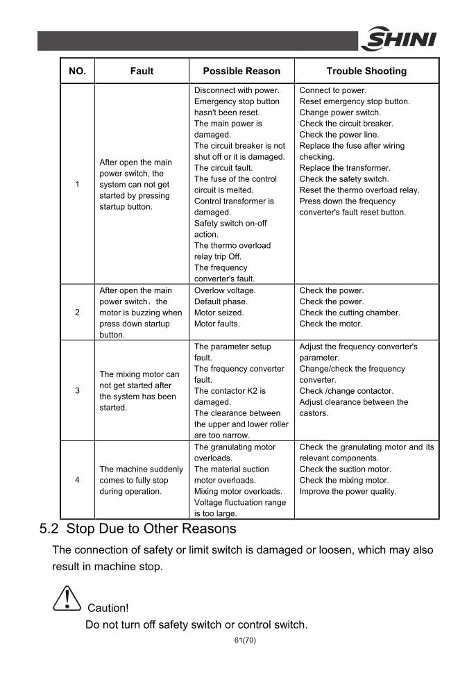
NO. Fault Possible Reason Trouble Shooting
1
After open the main power switch, the system can not get started by pressing startup button.
Disconnect with power. Emergency stop button hasn't been reset. The main power is damaged. The circuit breaker is not shut off or it is damaged. The circuit fault. The fuse of the control circuit is melted. Control transformer is damaged. Safety switch on-off action. The thermo overload relay trip Off. The frequency converter's fault.
Connect to power. Reset emergency stop button. Change power switch. Check the circuit breaker. Check the power line. Replace the fuse after wiring checking. Replace the transformer. Check the safety switch. Reset the thermo overload relay. Press down the frequency converter's fault reset button.
2
After open the main power switch,the motor is buzzing when press down startup button.
Overlow voltage. Default phase. Motor seized. Motor faults.
Check the power. Check the power. Check the cutting chamber. Check the motor.
3
The mixing motor can not get started after the system has been started.
The parameter setup fault. The frequency converter fault. The contactor K2 is damaged. The clearance between the upper and lower roller are too narrow.
Adjust the frequency converter's parameter. Change/check the frequency converter. Check /change contactor. Adjust clearance between the castors.
4 The machine suddenly comes to fully stop during operation.
The granulating motor overloads. The material suction motor overloads. Mixing motor overloads. Voltage fluctuation range is too large.
Check the granulating motor and its relevant components. Check the suction motor. Check the mixing motor. Improve the power quality.
5.2 Stop Due to Other Reasons The connection of safety or limit switch is damaged or loosen, which may also result in machine stop.
Caution! Do not turn off safety switch or control switch.
62(70)
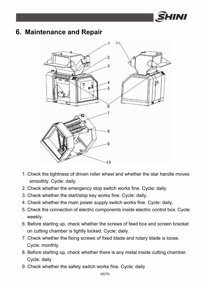
6. Maintenance and Repair
1. Check the tightness of driven roller wheel and whether the star handle moves smoothly. Cycle: daily.
2. Check whether the emergency stop switch works fine. Cycle: daily. 3. Check whether the start/stop key works fine. Cycle: daily. 4. Check whether the main power supply switch works fine. Cycle: daily. 5. Check the connection of electric components inside electric control box. Cycle:
weekly. 6. Before starting up, check whether the screws of feed box and screen bracket
on cutting chamber is tightly locked. Cycle: daily. 7. Check whether the fixing screws of fixed blade and rotary blade is loose.
Cycle: monthly 8. Before starting up, check whether there is any metal inside cutting chamber.
Cycle: daily 9. Check whether the safety switch works fine. Cycle: daily

63(70)
10. Check the belt tension. Cycle: half a year (or after 20-30h of full-load operation)
11. Before starting up, check whether the rolling drum moves fine. Cycle: daily 6.1 Repair
All the repair must be done by professionals to avoid damage to machine and harm to human body.
6.1.1 Blade replacement
Note! The rotary blade of granulator shall be under balanced stress. When blade installation, it may turn itself due to unbalanced stress!
Caution! When the center of gravity of blade is unstable, it can still turn itself.
The blade is very sharp-edged. Gloves shall be put on prior to operation.
Be very careful when operating to avoid injury! When maintaining, or replacing, please refer to 3.4 for installation of static blade and rotary blade. Imnfuse thread fixative (light green LOCTITE243 is recommended) into thread interface to fix each screw to prevent it from slip.
Warning! When dismantling or installing the rotary blade, no outside force can help you. Replace the blade yourself to minimize the chance of injuring more people.
Warning!
To avoid rotating, take a plank to block the rotary blade. Be careful when doing so because the blade is very sharp-edged.
Once the blade is replaced, replace the screws and gaskets with new ones.

64(70)
Before blade replacement, open the feed box and remove the storage box, screen and screen frame.
1) Dismantle the static blade
Note! To prevent the cutting tool from self rotating, take a plank to block it. 1. Take off the screw and the gasket. 2. Take out the static blade. 3. Clean the installation surface of the blade.
2) Dismantle the rotary blade 1. Open the feed box. 2. Loosen the hexagonal screw on the blade rest. c. Clean the whole rotary blade and the cutting chamber.
Caution! When loosening the last screw, you must press the blade block and the blade to avoid any injury.
3) Installation of blade Carefully clean the static blade and the rotary blade before their installation.
Warning! Once the blade is replaced, the screw and the gasket shall be totally replaced. First install the rear static blade and then the front one; install the rotary blade afterwards. See 3.4 Installation of static blade and rotary blade for detailed installation steps.
6.2 Transmission 6.2.1 Routine Preservation of Tooth Belt
The tooth belt is provided for the granulator according to the power of motor.
1) Check the tooth belt After running for 20~30 hours with full load, check the tension of ooth belt and its operation; then monthly check its wearing.

65(70)
2) Check the tension of tooth belt every 6 months Open the side plate of the control cabinet at the right of the granulator and check any damage or wearing of belt.
6.2.2 Daily Maintenance of V belt
The granulator is equipped with V belt according to motor’s power.
1) Check the V belt After 20-30h of full-load operation, it’s necessary to check the belt tension
and its operating situation. Check the wear situation of V belt every month after that.
2) Check the V belt every six months Open the side plate of control box on the right side of granulator. Turn the V
blet for several circles to check whether it’s damaged.
Note! Don't put your hand between the belt and the belt pulley to avoid any injury.
Check the tension of belt and adjust it when necessary. Apply force to check the tension of the belt. Apply the force F(150N) in the middle of belt pulley and measure the offset at the same time (the offset size depends on the center-to-center spacing L of belt pulley).
6.2.3 Adjustment of V belt
1) Open the shield door plank. 2) Open the fast pipe connector of extraction line end and then take out the
screen bracket. 3) Adjust two movable screws to change the clearance between the big belt

66(70)
pulley and the small one to adjust the belt tension. 4) Lock the movable screws.
Check the belt tension again after 20-30h of full-load operation.
Picture 6-1:Adjustment of Tooth Belt
6.3 Lubricating of Bearing 6.3.1 Lubrication
Xin Chang Long: FX-00 FX-000
Bp:BP Grease LGEP 2 ESSO:Beacon Ep2, Beacon EP2 Mobil:Mobilux EP2 Shell:Shell Alvania EP2 Texaco:Multifak Ep2, Novotex Grease EP2
6.4 Maintenance When carrying out maintenance, ensure that there is no material left in the granulator.
CAUTION! All stuff concerning repair must be conducted by professionals to avoid damage or harm to human body.
6.4.1 Daily Check
1) There is acryl shutter in the feed box. If the shutter is damaged, replace it immediately. Otherwise the fragment of the shutter will damage the blades in the cutting chamber.
2) Check whether the Emergency Stop works properly. Start the machine and then stop it via Emergency Stop. Rotate the button an ti-clockWise to reset

67(70)
the Emergency Stop. 6.4.2 Weekly Check
1) Check the power wire to see whether there is any damage. If so, replace it immediately.
2) Check the safety switch. 6.4.3 Monthly Check
1) Check the belt to see whether there is some damage. Check the belt's tensility every 6 months. More details to see chapter 6.2 Transmission.
2) Check the blades and screws to see if they get loose. 6.5 Cleaning
When opening the feed box, be careful not to touch the blade that is very sharp-edged and may injure people.
1) Before the machine is stopped, check the feed box is empty. 2) Clean the outer surface of feed box. 3) Clean the material fender of feed box with the deduster. 4) Close the main power switch. 5) Loosen the long hexagonal screw and then open backWards the feed box. 6) Clean the inner surface of feed box. 7) Remove the screen bracket. 8) Clean the screen bracket. 9) Clean the cutting chamber internally and externally. 10) Clean the belt pulley with bright shining dedusting agent.
6.6 Maintenance and Preservation of Frequency Converter
Note! Only professional staff can maintain and preserve the frequency converter; otherwise it may result in bodily injury or damage to the granulator!
Note!

68(70)
Only professional staff can check the signal during running; otherwise it may result in bodily injury or damage to the granulator!
Danger! Maintenance and preservation of frequency converter cannot be carried out unless the light "harge" of the converter is off; otherwise it may result in bodily injury or damage to the facilities!
6.6.1 Routine Preservation
Routine check activities
1) Check any abnormal change of sound during motor running. 2) Check any material vibration during motor running. 3) Check any change of frequency converter installation environment. 4) Check normal working of the heat dissipate fan of the converter. 5) Check the converter is not overheated.
Routine cleaning
1) Keep the converter clean all the time. 2) Effectively remove oil stain from the heat dissipate fan of the converter.
6.6.2 Periodic Check
1) Check the air duct and periodically clean it. 2) Check the screw isn't loosened. 3) Check the converter isn't eroded. 4) Check any arcing of terminal. 5) Test of main circuit insulation.

69(70)
6.7 Maintenance Schedule 6.7.1 About the Machine
Model SN Manufacture date
Voltage Ф V Frequency Hz Power kW
6.7.2 Check After Installation
Check if pipe connections are firmed locked by clips.
Check the gap between fixed blade and rotating blade. (0.1~0.15mm).
Check the rotating balance of the belt wheel.
Electrical Installation
Voltage: V Hz
Specs of the fuse: 1 Phase A 3 Phase A
Check phase sequence of the power supply.
Check the rotating direction of the conveying blower.
6.7.3 Daily Check
Check main power switch. Check emergency stop button. Check start / stop button. Check material check plate (strip) is perfect or not. Check whether emergency stop and safety switch works normally. Clean screen and feeding hooper. Check whether start, stop and power switches are normal.
6.7.4 Weekly Check
Check all the electrical cables. Check if there are loose connections of electrical components. Check blade condition. Check whether set screws in fixed and rotate blades are under looseness. Check if there is abnormal noise, vibration and heat in reduction gear. Check the cracking window
6.7.5 Monthly Check
Check the condition of rolling device.

70(70)
Check the delay function of the material feed motor. Check the motor overload protector. Check the tightness of the blades. Check whether clamp ring of pulley is fastened. Check belt tension.
6.7.6 Check Half-yearly or Every 1000 Running Hours
Check the tensility of the belt Check the lubrication of bearing、motor and hopper's rotating shaft Check the two bearing blocks
6.7.7 3 year Checking
PC board renewal. No fuse breaker renewal.