roll-to-roll microcontact printing of flexible aluminum
TRANSCRIPT

Roll-to-Roll Microcontact Printing of Flexible AluminumSubstrates Using Octadecylphosphonic Acid (ODPA)
The MIT Faculty has made this article openly available. Please share how this access benefits you. Your story matters.
Citation Merian, Chris et al. “Roll-to-Roll Microcontact Printing of FlexibleAluminum Substrates Using Octadecylphosphonic Acid (ODPA).”ASME 2015 International Mechanical Engineering Congress andExposition, 13-19 November, 2015, Houston, Texas, USA, ASME,2015. © 2015 by ASME
As Published http://dx.doi.org/10.1115/IMECE2015-51184
Publisher American Society of Mechanical Engineers (ASME)
Version Final published version
Citable link http://hdl.handle.net/1721.1/108483
Terms of Use Article is made available in accordance with the publisher'spolicy and may be subject to US copyright law. Please refer to thepublisher's site for terms of use.

ROLL-TO-ROLL MICROCONTACT PRINTING OF FLEXIBLE ALUMINUM SUBSTRATES USING OCTADECYLPHOSPHONIC ACID (ODPA)
Chris Merian Massachusetts Institute of Technology
Cambridge, Massachusetts, USA
Xian Du Massachusetts Institute of Technology
Cambridge, Massachusetts, USA
David Hardt Massachusetts Institute of Technology
Cambridge, Massachusetts, USA
Hussain AlQahtani King Fahd University of Petroleum and Minerals
Dhahran, Saudi Arabia
ABSTRACT Soft-lithography, or the printing of self-assembling
molecular inks at micro or sub-micron scale holds the promise of large-scale surface patterning for a variety of applications. One key to the ultimate utility of this concept is continuous roll-to-roll printing on lost-cost flexible substrates. Accordingly, this paper discusses the basic processes involved in roll-to-roll printing of octadecylphosphonic acid (ODPA) on aluminum-coated PET substrates using novel cylindrical stamps cast from PDMS. In addition to printing, visualization of the pattern is achieved through controlled condensation of water vapor and by a post-printing acid etch. By using a roll-to-roll configuration, along with continuous stamps and measurements that can permit real-time online quality monitoring, this method represents a significant step forward in making soft lithography a commercially viable process.
INTRODUCTION Microcontact printing (µCP) is a specific form of soft lithography, which is a technique developed by Xia and Whitesides [1] to create sub-micron surface deposits using compliant patterned printing stamps. These stamps are typically cast from the elastomer polydimethylsiloxane (PDMS) and feature replication down to <80 nm has been demonstrated [2]. The process involves the transfer of self-assembling molecular monolayers from patterned elastomer stamps [3,4] and has emerged in the last decade as a leading candidate for full-scale commercial production of nano-patterned surfaces [5]. While rooted in the ancient technology
of “printing” it differs not only because of the sub-micron features size, but also in the basic physics of ink transfer. The typical “inks” used are in fact a class of self-assembling molecules (typically alkanethiols) that are applied dry to the stamp and transfer in monolayers. Once transferred these molecules self-assemble or orient themselves, which changes the surface properties in significant ways. Depending on the substrate used, these changes can lead to significant variation in surface energy[6], serve as a chemical etch resist [7], or, if combined with appropriate catalysts, provide a template for metal, silicon or CNT growth [8]. In all these applications, the key manufacturing challenge is to consistently create the basic surface pattern on a continuous, large area, high-rate basis. That large scale, continuous production problem is the challenge addressed by this research. STATE OF THE ART
To date the bulk of the literature concerns studies of the basic chemistry and transfer physics of the process with little attention paid to scale-up issues [9]. The chemistry of the thiol inks and the surface characterizations are well documented (e.g. [7]) and considerable work has been done on producing small, flat micro-patterned stamps. The current commercial method for printing small arrays is based on ink-jet technology, and is limited to about a 5-10 micron pitch and has the typical speed limits of a serial process, even with ganged heads. The volume production needs for PV and other large surface area technologies demands an inherently faster production method. By contrast, µCP has not only been shown to allow features as small as 80 nm [2], recent work has
Proceedings of the ASME 2015 International Mechanical Engineering Congress and Exposition IMECE2015
November 13-19, 2015, Houston, Texas
IMECE2015-51184
1 Copyright © 2015 by ASME
Downloaded From: http://proceedings.asmedigitalcollection.asme.org/pdfaccess.ashx?url=/data/conferences/asmep/86936/ on 03/02/2017 Terms of Use: http://www.asme.org/about-asme/terms-of-use
demonstrated the possibility of printing at speeds up to 100 m/min. [10]. However, the latter work also demonstrated that significant problems with basic stamp production and printing consistency exist at all speeds. Thus, while the process has great potential, there has yet to be a concerted effort at understanding both the fundamental and practical issues involved in a transition to full-scale production.
Earlier work has identified several key issues that are vital
to the scale-up of this technology: • Continuous, uniform cylindrical tooling. • Equipment for precise contact region manipulation. • A means for measuring the printing performance in-
process. • A method for overall process control.
The larger context of the work reported here includes all of these factors to enable a large area high rate microcontact printing process capable of micron-scale patterning a flexible substrate material.
The need for continuous cylindrical tools with appropriate
micro-scale features and substrate uniformity to produce consistent, large area printing has been addressed by Petrzelka and Hardt [11] and Nietner and Hardt [12]. Using a novel centrifugal casting and cylindrical mask-less patterning method, seamless cylindrical PDMS tools, such that shown in Fig. 1 can be produced.
Figure 1. A centrifugal casting stamp with 30 µm width 20 µm high features grouped in 1 mm bands [12]
The next element of scale-up is the ability to control and
maintain the region of contact between the rolling stamp and the moving web. Given the desire to print with features as small is 1 µm, a precision machine with sub-micron resolution is required. A flexure based device for this purpose was demonstrated for roll to plate printing by Petrzelka and Hardt [13]. More recently, Libert [14] developed a precision roll positioning system for continuous roll-to-roll operation that is capable of controlling a 15 cm wide print region with position resolution below 100 nm and force resolution of 0.02 N. This
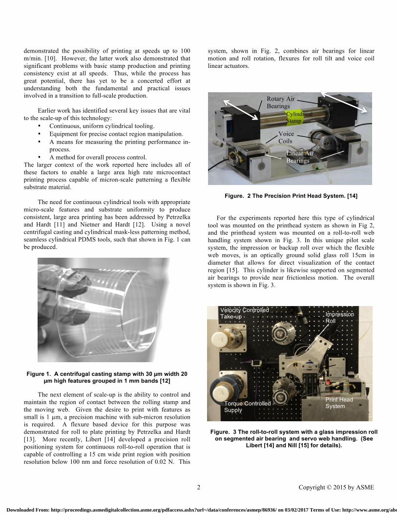
system, shown in Fig. 2, combines air bearings for linear motion and roll rotation, flexures for roll tilt and voice coil linear actuators.
Figure. 2 The Precision Print Head System. [14]
For the experiments reported here this type of cylindrical
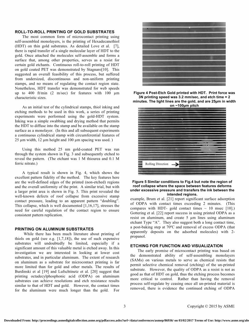
tool was mounted on the printhead system as shown in Fig 2, and the printhead system was mounted on a roll-to-roll web handling system shown in Fig. 3. In this unique pilot scale system, the impression or backup roll over which the flexible web moves, is an optically ground solid glass roll 15cm in diameter that allows for direct visualization of the contact region [15]. This cylinder is likewise supported on segmented air bearings to provide near frictionless motion. The overall system is shown in Fig. 3.
Figure. 3 The roll-to-roll system with a glass impression roll on segmented air bearing and servo web handling. (See
Libert [14] and Nill [15] for details).
Voice Coils
Linear Air Bearings
Rotary Air Bearings
Cylindrical Stamp
Impression Roll
Rotary Air Bearings
Print Head System
Velocity Controlled Take-up
Torque Controlled Supply
2 Copyright © 2015 by ASME
Downloaded From: http://proceedings.asmedigitalcollection.asme.org/pdfaccess.ashx?url=/data/conferences/asmep/86936/ on 03/02/2017 Terms of Use: http://www.asme.org/about-asme/terms-of-use
ROLL-TO-ROLL PRINTING OF GOLD SUBSTRATES The most common form of microcontact printing using
self-assembled monolayers, is the printing of Hexadecanethiol (HDT) on thin gold substrates. As detailed Love et al. [7], there is rapid transfer of a single molecular layer of HDT to the gold. Once attached the molecules self-assemble and forms a surface that, among other properties, serves as a resist for certain gold etchants. Continuous roll-to-roll printing of HDT on gold coated PET was demonstrated by Stagnaro[10]. This suggested an overall feasibility of this process, but suffered from undersized, discontinuous and non-uniform printing stamps, and no means of regulating the contact region state. Nonetheless, HDT transfer was demonstrated for web speeds up to 400 ft/min (2 m/sec) for features with 100 µm characteristic sizes.
As an initial test of the cylindrical stamps, thiol inking and
etching methods to be used in this work, a series of printing experiments were performed using the gold-HDT system. Inking was a simple swabbing and drying method that permits the HDT to diffuse into the stamp and be available on the stamp surface as a monolayer. (In this and all subsequent experiments a continuous cylindrical stamp with circumferential features of 25 µm width, 12 µm height and 100 µm spacing was used. )
Using this method 25 nm gold-coated PET was run
through the system shown in Fig. 3 and subsequently etched to reveal the pattern. (The etchant was 1 M thiourea and 0.1 M ferric nitrate.)
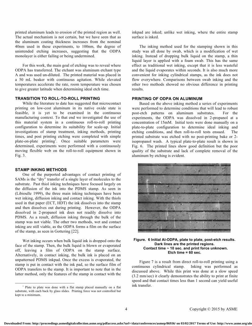
A typical result is shown in Fig. 4, which shows the
excellent pattern fidelity of the method. The key features here are the well-defined edges of the printed (non-etched) regions and the overall uniformity of the print. A similar trial, but with a larger print area is shown in Fig. 5. This print revealed the well-known defects of roof collapse from excessive stamp contact pressure, leading to an apparent pattern “doubling”. This collapse, which is well documented [1,16,17], stresses the need for careful regulation of the contact region to ensure consistent pattern replication.
PRINTING ON ALUMINUM SUBSTRATES While there has been much literature about printing of
thiols on gold (see e.g. [1,7,18]), the use of such expensive substrates will undoubtedly be limited, especially if a significant amount of this valuable metal is etched away. In this investigation we are interested in looking at lower cost substrates, and in particular aluminum. The extent of research on aluminum as a substrate for microcontact printing is far more limited than for gold and other metals. The results of Burdinski et al [19] and Lufschtinetz et al. [20] suggest that printing octadecylphosphonic acid (ODPA) on aluminum substrates can achieve resolutions and etch resistance results similar to that of HDT and gold. However, the contact times for the aluminum were much longer than the gold. For
example, Brum et al. [21] report significant surface adsorption of ODPA with contact times exceeding 2 minutes. (This compares with HDT- gold contact times ~ 10 msec [10].) Gottering et al. [22] report success in using printed ODPA as a resist on aluminum, and create 5 µm lines using aluminum etchant Type “A”. They also suggest both a long contact time, a post-baking step at 70ºC and removal of excess ODPA (that apparently deposits on the adsorbed molecules) with 2-propanol.
ETCHING FOR FUNCTION AND VISUALIZATION The early promise of microcontact printing was based on
the demonstrated ability of self-assembling monolayers (SAMs) on various metals to serve as chemical resists that permit selective chemical removal (etching) of the un-printed substrate. However, the quality of ODPA as a resist is not as good as that of HDT on gold, thus the etching process becomes more critical to control. Rather than having the removal process self-regulate by ceasing once all un-printed material is removed, there is evidence the continued etching of ODPA
Figure 4 Post-Etch Gold printed with HDT. Print force was 3N printing speed was 3.2 mm/sec, and etch time = 2
minutes. The light lines are the gold, and are 25µm in width on ~100µm pitch
Figure 5 Similar conditions to Fig.4 but note the region of roof collapse where the space between features deforms
under excessive pressure and transfers the ink between the intended regions.
Rolling Direction
3 Copyright © 2015 by ASME
Downloaded From: http://proceedings.asmedigitalcollection.asme.org/pdfaccess.ashx?url=/data/conferences/asmep/86936/ on 03/02/2017 Terms of Use: http://www.asme.org/about-asme/terms-of-use
printed aluminum leads to erosion of the printed region as well. The actual mechanism is not certain, but we have seen that as the aluminum coating thickness increases from the nominal 40nm used in these experiments, to 100nm, the degree of unintended etching increases, suggesting that the ODPA monolayer is either failing or being undermined.
For this work, the main goal of etching was to reveal where
ODPA has transferred. The etchant was aluminum etchant type A and was used un-diluted. The printed material was placed in a 50 mL beaker with continuous agitation. While elevated temperatures accelerate the rate, room temperature was chosen to give greater latitude when determining ideal etch time.
TRANSITION TO ROLL-TO-ROLL PRINTING
While the literature to date has suggested that microcontact printing on low-cost aluminum in its native oxide state is feasible, it is yet to be examined in the continuous manufacturing context. To that end we investigated the use of this material system in a continuous roll-to-roll printing configuration to determine its suitability for scale-up. Initial investigations of stamp treatment, inking methods, printing times, and post printing etching were completed with simple plate-on-plate printing1. Once suitable parameters were determined, experiments were performed with a continuously moving flexible web on the roll-to-roll equipment shown in Fig. 3.
STAMP INKING METHODS One of the purported advantages of contact printing of
SAMs is the “dry” transfer of a single layer of molecules to the substrate. Past thiol inking techniques have focused largely on the diffusion of the ink into the PDMS stamp. As seen in (Libioulle 1999), the three main inking techniques have been wet inking, diffusion inking and contact inking. With the thiols used in that paper (ECT, HDT) the ink dissolves into the stamp and then dissolves out during printing. However, the ODPA dissolved in 2-propanol ink does not readily dissolve into PDMS. As a result, diffusion inking through the bulk of the stamp was not viable. The other two methods, wet and contact inking are still viable, as the ODPA forms a film on the surface of the stamp, as seen in Gottering [22].
Wet inking occurs when bulk liquid ink is dropped onto the
face of the stamp. Then, the bulk liquid is blown or evaporated off, leaving a film of ODPA on the stamp surface. Alternatively, in contact inking, the bulk ink is placed on an unpatterned PDMS inkpad. Once the excess is evaporated, the stamp is put in contact with the ink pad, so the surface film of ODPA transfers to the stamp. It is important to note that in the latter method, only the features of the stamp in contact with the
1 Plate to plate was done with a flat stamp placed manually on a flat
substrate, with each back by glass slides. Printing force was not controlled but kept to a minimum.
inkpad are inked; unlike wet inking, where the entire stamp surface is inked.
The inking method used for the stamping shown in this
study was all done by swab, which is a modification of wet inking. Instead of dropping bulk liquid on the stamp, a thin liquid layer is applied with a foam swab. This has the same effect as traditional wet inking, except that it is less wasteful and the liquid evaporates within seconds. It is also much more convenient for inking cylindrical stamps, as the ink does not flow everywhere. Comparisons between swab inking and the other two methods showed no obvious difference in printing results.
PRINTING OF ODPA ON ALUMINUM Based on the above inking method a series of experiments
were performed to determine conditions that will lead to robust post-etch patterns on aluminum substrates. For the experiments, the ODPA was dissolved in 2-propanol at a concentration of 15mM. Initial tests were done manually on a plate-to-plate configuration to determine ideal inking and etching conditions, and then roll-to-roll tests ensued. The printed substrate was etched with no post-printing bake or 2-isopropanol wash. A typical plate-to-plate result is shown in Fig. 6. The printed lines show good definition but the poor quality of the substrate and lack of complete removal of the aluminum by etching is evident.
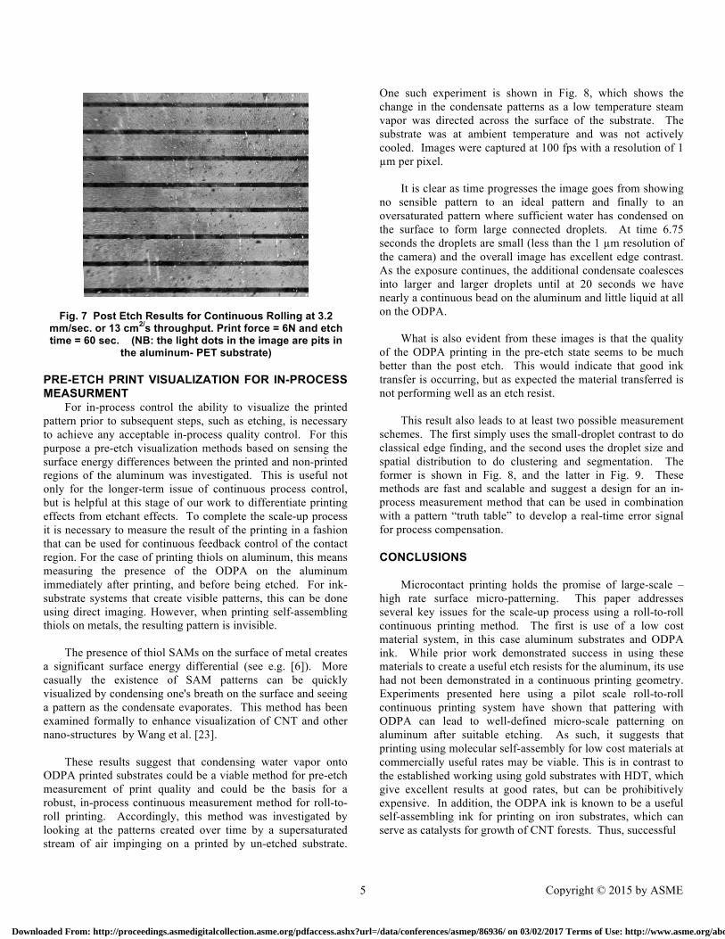
Figure 7 is a result from direct roll-to-roll printing using a continuous cylindrical stamp. Inking was performed as discussed above. While this print was done at a slow speed (3.2 mm/sec) it clearly demonstrates the ability to print at finite speed and that contact times less than 1 second can yield useful ink transfer.
Figure. 6 Initial Al-ODPA, plate to plate, post-etch results. Dark lines are the printed regions.
Contact time ~ 10 sec. and print force unknown. Etch time = 60 sec.
4 Copyright © 2015 by ASME
Downloaded From: http://proceedings.asmedigitalcollection.asme.org/pdfaccess.ashx?url=/data/conferences/asmep/86936/ on 03/02/2017 Terms of Use: http://www.asme.org/about-asme/terms-of-use
PRE-ETCH PRINT VISUALIZATION FOR IN-PROCESS MEASURMENT
For in-process control the ability to visualize the printed pattern prior to subsequent steps, such as etching, is necessary to achieve any acceptable in-process quality control. For this purpose a pre-etch visualization methods based on sensing the surface energy differences between the printed and non-printed regions of the aluminum was investigated. This is useful not only for the longer-term issue of continuous process control, but is helpful at this stage of our work to differentiate printing effects from etchant effects. To complete the scale-up process it is necessary to measure the result of the printing in a fashion that can be used for continuous feedback control of the contact region. For the case of printing thiols on aluminum, this means measuring the presence of the ODPA on the aluminum immediately after printing, and before being etched. For ink-substrate systems that create visible patterns, this can be done using direct imaging. However, when printing self-assembling thiols on metals, the resulting pattern is invisible.
The presence of thiol SAMs on the surface of metal creates
a significant surface energy differential (see e.g. [6]). More casually the existence of SAM patterns can be quickly visualized by condensing one's breath on the surface and seeing a pattern as the condensate evaporates. This method has been examined formally to enhance visualization of CNT and other nano-structures by Wang et al. [23].
These results suggest that condensing water vapor onto
ODPA printed substrates could be a viable method for pre-etch measurement of print quality and could be the basis for a robust, in-process continuous measurement method for roll-to-roll printing. Accordingly, this method was investigated by looking at the patterns created over time by a supersaturated stream of air impinging on a printed by un-etched substrate.
One such experiment is shown in Fig. 8, which shows the change in the condensate patterns as a low temperature steam vapor was directed across the surface of the substrate. The substrate was at ambient temperature and was not actively cooled. Images were captured at 100 fps with a resolution of 1 µm per pixel.
It is clear as time progresses the image goes from showing
no sensible pattern to an ideal pattern and finally to an oversaturated pattern where sufficient water has condensed on the surface to form large connected droplets. At time 6.75 seconds the droplets are small (less than the 1 µm resolution of the camera) and the overall image has excellent edge contrast. As the exposure continues, the additional condensate coalesces into larger and larger droplets until at 20 seconds we have nearly a continuous bead on the aluminum and little liquid at all on the ODPA.
What is also evident from these images is that the quality
of the ODPA printing in the pre-etch state seems to be much better than the post etch. This would indicate that good ink transfer is occurring, but as expected the material transferred is not performing well as an etch resist.
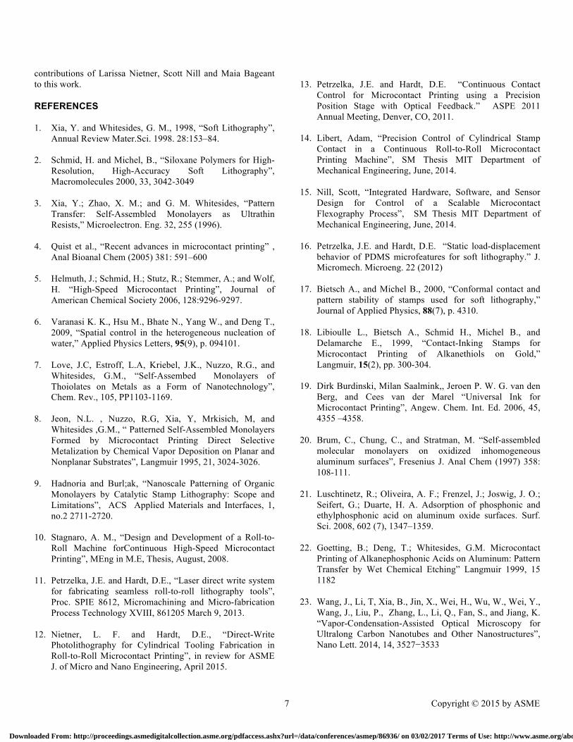
This result also leads to at least two possible measurement
schemes. The first simply uses the small-droplet contrast to do classical edge finding, and the second uses the droplet size and spatial distribution to do clustering and segmentation. The former is shown in Fig. 8, and the latter in Fig. 9. These methods are fast and scalable and suggest a design for an in-process measurement method that can be used in combination with a pattern “truth table” to develop a real-time error signal for process compensation.
CONCLUSIONS
Microcontact printing holds the promise of large-scale –high rate surface micro-patterning. This paper addresses several key issues for the scale-up process using a roll-to-roll continuous printing method. The first is use of a low cost material system, in this case aluminum substrates and ODPA ink. While prior work demonstrated success in using these materials to create a useful etch resists for the aluminum, its use had not been demonstrated in a continuous printing geometry. Experiments presented here using a pilot scale roll-to-roll continuous printing system have shown that pattering with ODPA can lead to well-defined micro-scale patterning on aluminum after suitable etching. As such, it suggests that printing using molecular self-assembly for low cost materials at commercially useful rates may be viable. This is in contrast to the established working using gold substrates with HDT, which give excellent results at good rates, but can be prohibitively expensive. In addition, the ODPA ink is known to be a useful self-assembling ink for printing on iron substrates, which can serve as catalysts for growth of CNT forests. Thus, successful
Fig. 7 Post Etch Results for Continuous Rolling at 3.2 mm/sec. or 13 cm2/s throughput. Print force = 6N and etch time = 60 sec. (NB: the light dots in the image are pits in
the aluminum- PET substrate)
5 Copyright © 2015 by ASME
Downloaded From: http://proceedings.asmedigitalcollection.asme.org/pdfaccess.ashx?url=/data/conferences/asmep/86936/ on 03/02/2017 Terms of Use: http://www.asme.org/about-asme/terms-of-use
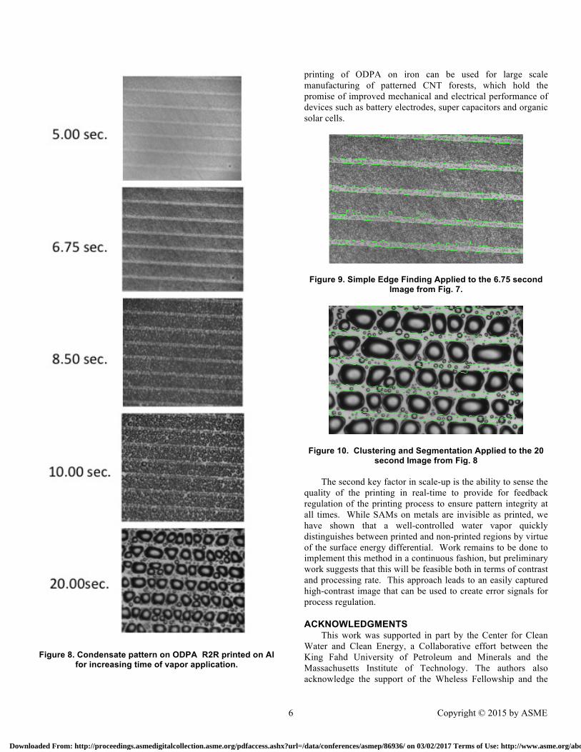
Figure 8. Condensate pattern on ODPA R2R printed on Al
for increasing time of vapor application.
printing of ODPA on iron can be used for large scale manufacturing of patterned CNT forests, which hold the promise of improved mechanical and electrical performance of devices such as battery electrodes, super capacitors and organic solar cells.
Figure 9. Simple Edge Finding Applied to the 6.75 second Image from Fig. 7.
Figure 10. Clustering and Segmentation Applied to the 20 second Image from Fig. 8
The second key factor in scale-up is the ability to sense the
quality of the printing in real-time to provide for feedback regulation of the printing process to ensure pattern integrity at all times. While SAMs on metals are invisible as printed, we have shown that a well-controlled water vapor quickly distinguishes between printed and non-printed regions by virtue of the surface energy differential. Work remains to be done to implement this method in a continuous fashion, but preliminary work suggests that this will be feasible both in terms of contrast and processing rate. This approach leads to an easily captured high-contrast image that can be used to create error signals for process regulation.
ACKNOWLEDGMENTS This work was supported in part by the Center for Clean
Water and Clean Energy, a Collaborative effort between the King Fahd University of Petroleum and Minerals and the Massachusetts Institute of Technology. The authors also acknowledge the support of the Wheless Fellowship and the
6 Copyright © 2015 by ASME
Downloaded From: http://proceedings.asmedigitalcollection.asme.org/pdfaccess.ashx?url=/data/conferences/asmep/86936/ on 03/02/2017 Terms of Use: http://www.asme.org/about-asme/terms-of-use
contributions of Larissa Nietner, Scott Nill and Maia Bageant to this work.
REFERENCES 1. Xia, Y. and Whitesides, G. M., 1998, “Soft Lithography”,
Annual Review Mater.Sci. 1998. 28:153–84.
2. Schmid, H. and Michel, B., “Siloxane Polymers for High-Resolution, High-Accuracy Soft Lithography”, Macromolecules 2000, 33, 3042-3049
3. Xia, Y.; Zhao, X. M.; and G. M. Whitesides, “Pattern Transfer: Self-Assembled Monolayers as Ultrathin Resists,” Microelectron. Eng. 32, 255 (1996).
4. Quist et al., “Recent advances in microcontact printing” , Anal Bioanal Chem (2005) 381: 591–600
5. Helmuth, J.; Schmid, H.; Stutz, R.; Stemmer, A.; and Wolf, H. “High-Speed Microcontact Printing”, Journal of American Chemical Society 2006, 128:9296-9297.
6. Varanasi K. K., Hsu M., Bhate N., Yang W., and Deng T., 2009, “Spatial control in the heterogeneous nucleation of water,” Applied Physics Letters, 95(9), p. 094101.
7. Love, J.C, Estroff, L.A, Kriebel, J.K., Nuzzo, R.G., and Whitesides, G.M., “Self-Assembed Monolayers of Thoiolates on Metals as a Form of Nanotechnology”, Chem. Rev., 105, PP1103-1169.
8. Jeon, N.L. , Nuzzo, R.G, Xia, Y, Mrkisich, M, and Whitesides ,G.M., “ Patterned Self-Assembled Monolayers Formed by Microcontact Printing Direct Selective Metalization by Chemical Vapor Deposition on Planar and Nonplanar Substrates”, Langmuir 1995, 21, 3024-3026.
9. Hadnoria and Burl;ak, “Nanoscale Patterning of Organic Monolayers by Catalytic Stamp Lithography: Scope and Limitations”, ACS Applied Materials and Interfaces, 1, no.2 2711-2720.
10. Stagnaro, A. M., “Design and Development of a Roll-to-Roll Machine forContinuous High-Speed Microcontact Printing”, MEng in M.E, Thesis, August, 2008.
11. Petrzelka, J.E. and Hardt, D.E., “Laser direct write system for fabricating seamless roll-to-roll lithography tools”, Proc. SPIE 8612, Micromachining and Micro-fabrication Process Technology XVIII, 861205 March 9, 2013.
12. Nietner, L. F. and Hardt, D.E., “Direct-Write Photolithography for Cylindrical Tooling Fabrication in Roll-to-Roll Microcontact Printing”, in review for ASME J. of Micro and Nano Engineering, April 2015.
13. Petrzelka, J.E. and Hardt, D.E. “Continuous Contact
Control for Microcontact Printing using a Precision Position Stage with Optical Feedback.” ASPE 2011 Annual Meeting, Denver, CO, 2011.
14. Libert, Adam, “Precision Control of Cylindrical Stamp Contact in a Continuous Roll-to-Roll Microcontact Printing Machine”, SM Thesis MIT Department of Mechanical Engineering, June, 2014.
15. Nill, Scott, “Integrated Hardware, Software, and Sensor Design for Control of a Scalable Microcontact Flexography Process”, SM Thesis MIT Department of Mechanical Engineering, June, 2014.
16. Petrzelka, J.E. and Hardt, D.E. “Static load-displacement behavior of PDMS microfeatures for soft lithography.” J. Micromech. Microeng. 22 (2012)
17. Bietsch A., and Michel B., 2000, “Conformal contact and pattern stability of stamps used for soft lithography,” Journal of Applied Physics, 88(7), p. 4310.
18. Libioulle L., Bietsch A., Schmid H., Michel B., and Delamarche E., 1999, “Contact-Inking Stamps for Microcontact Printing of Alkanethiols on Gold,” Langmuir, 15(2), pp. 300-304.
19. Dirk Burdinski, Milan Saalmink,, Jeroen P. W. G. van den Berg, and Cees van der Marel “Universal Ink for Microcontact Printing”, Angew. Chem. Int. Ed. 2006, 45, 4355 –4358.
20. Brum, C., Chung, C., and Stratman, M. “Self-assembled molecular monolayers on oxidized inhomogeneous aluminum surfaces”, Fresenius J. Anal Chem (1997) 358: 108-111.
21. Luschtinetz, R.; Oliveira, A. F.; Frenzel, J.; Joswig, J. O.; Seifert, G.; Duarte, H. A. Adsorption of phosphonic and ethylphosphonic acid on aluminum oxide surfaces. Surf. Sci. 2008, 602 (7), 1347–1359.
22. Goetting, B.; Deng, T.; Whitesides, G.M. Microcontact Printing of Alkanephosphonic Acids on Aluminum: Pattern Transfer by Wet Chemical Etching” Langmuir 1999, 15 1182
23. Wang, J., Li, T, Xia, B., Jin, X., Wei, H., Wu, W., Wei, Y., Wang, J., Liu, P., Zhang, L., Li, Q., Fan, S., and Jiang, K. “Vapor-Condensation-Assisted Optical Microscopy for Ultralong Carbon Nanotubes and Other Nanostructures”, Nano Lett. 2014, 14, 3527−3533
7 Copyright © 2015 by ASME
Downloaded From: http://proceedings.asmedigitalcollection.asme.org/pdfaccess.ashx?url=/data/conferences/asmep/86936/ on 03/02/2017 Terms of Use: http://www.asme.org/about-asme/terms-of-use