rolling bearings for the paper industry: products - schaeffler group
TRANSCRIPT

Rolling Bearingsfor the Paper Industry
Products · Service Design · Dimensioning

A Partnership in PaperWe offer a complete Paper Mill
Program that complements our DistributorNetwork.
We are committed to the Pulp & PaperIndustry to assure a total Quality Processfrom start to finish.
Our total 10-point concept from Or derEntry to Proactive Maintenance bringscost savings on a continual basis.
1. Innovation and Quality2. Global Resources and Support3. Products4. Inventory Review5. Stock Management6. Training Program7. Technical Service8. Proactive Maintenance9. Communication10. Documented Savings

Rolling Bearings for the Paper IndustryProducts · Service · Design · Dimensioning
Publ. No. WL 13 103/2 EA
Status 2004

Contents
FAG 2
1 FAG prod ucts and ser vic esfor the paper indus try (out line) . . . . . . . . . . . . . . . 3
1.1 Standard roll ing bear ings . . . . . . . . . . . . . . . . . . . . . 41.2 Special prod ucts . . . . . . . . . . . . . . . . . . . . . . . . . . . . 51.3 Service range . . . . . . . . . . . . . . . . . . . . . . . . . . . . . . 51.4 Suffixes, tech ni cal spec ifi ca tions . . . . . . . . . . . . . . . . 6
2 Requirements on paper machine bear ings . . . . . . . 7
3 Examples of bear ing arrange mentsfor paper machines . . . . . . . . . . . . . . . . . . . . . . . . . 8
3.1 Wet end sec tion . . . . . . . . . . . . . . . . . . . . . . . . . . . . 83.1.1 Forming roll . . . . . . . . . . . . . . . . . . . . . . . . . . . . . . 93.1.2 Suction roll . . . . . . . . . . . . . . . . . . . . . . . . . . . . . . . 103.1.3 Center press roll . . . . . . . . . . . . . . . . . . . . . . . . . . . . 123.1.4 Anti-deflec tion roll . . . . . . . . . . . . . . . . . . . . . . . . . 133.2 Dryer sec tion . . . . . . . . . . . . . . . . . . . . . . . . . . . . . . 143.2.1 Guide roll . . . . . . . . . . . . . . . . . . . . . . . . . . . . . . . . 143.2.2 Dryer roll . . . . . . . . . . . . . . . . . . . . . . . . . . . . . . . . . 163.3 Calender and fin ish ing group . . . . . . . . . . . . . . . . . 183.3.1 Calender ther mo roll . . . . . . . . . . . . . . . . . . . . . . . . 183.3.2 Spreader roll . . . . . . . . . . . . . . . . . . . . . . . . . . . . . . 20
4 FAG ser vice for more oper a tion al reli abil ity . . . . . . 214.1 Storage of roll ing bear ings . . . . . . . . . . . . . . . . . . . . 214.2 Preparations for mount ing and dis mount ing . . . . . . 214.3 Mounting and dis mount ing with cylin dri cal
and tapered mat ing sur fac es . . . . . . . . . . . . . . . . . . . 214.4 Fits and tol er anc es . . . . . . . . . . . . . . . . . . . . . . . . . . 234.5 Monitoring and ana lys ing bear ings . . . . . . . . . . . . . 264.6 PC pro grams for cal cu lat ing and
design ing roll ing bear ings . . . . . . . . . . . . . . . . . . . . 284.7 FAG mount ing ser vice . . . . . . . . . . . . . . . . . . . . . . . 284.8 FAG train ing cours es . . . . . . . . . . . . . . . . . . . . . . . . 284.9 Selection of pub li ca tions . . . . . . . . . . . . . . . . . . . . . 29
5 Dimensioning and lubri cat ing roll ing bear ings . . . 305.1 Dimensioning . . . . . . . . . . . . . . . . . . . . . . . . . . . . . 305.2 Lubrication . . . . . . . . . . . . . . . . . . . . . . . . . . . . . . . 325.2.1 Grease lubri ca tion . . . . . . . . . . . . . . . . . . . . . . . . . . 325.2.2 Oil lubri ca tion . . . . . . . . . . . . . . . . . . . . . . . . . . . . . 34
6 Tables . . . . . . . . . . . . . . . . . . . . . . . . . . . . . . . . . . . 386.1 Conversion . . . . . . . . . . . . . . . . . . . . . . . . . . . . . . . 386.2 Radial clear ance, radi al clear ance reduc tion . . . . . . . 39

Products and ser vices for the paper indus try
1 FAG prod ucts and ser vic es for the paper indus try
FAG has an exten sive pro gramme ofprod ucts and ser vic es for the paper indus -try.
The roll ing bear ing demand in thisfield focuss es on stan dard roll ing bear -ings, that is roll ing bear ings with stan dar -dised main dimen sions.
In pulp prep ar a tion, these are, forexam ple, spher i cal roll er bear ings andcylin dri cal roll er bear ings. The spher i calroll er bear ing dom i nates in paper mak -ing. Deep groove ball bear ings, angu larcon tact ball bear ings, and tapered roll erbear ings are found in acces so ry units ofpaper mak ing machines ( motors, gears,fans, pumps). Spherical roll er bear ings,angu lar con tact ball bear ings and cylin -dri cal roll er bear ings are typ i cal stan dardroll ing bear ings in the field of fin ish ingand con vert ing. FAG also sup plies acces -so ries and hous ings suit able for stan dardroll ing bear ings.
Spherical roll er bear ings with an out -side diam e ter of > 320 mm, which arepar tic u lar ly pop u lar, are com piled inFAG Paper Scope. It should improveprod uct avail abil ity espe cial ly for the spare parts demand of paper mills. FAGPaper Scope exclu sive ly con tains prod -ucts which are impor tant in the paperindus try but which are not required on areg u lar basis and have wide ly var y ing usage lev els. They are spher i cal roll erbear ings of the pop u lar series 230, 231,232 and 239 with design varie ty andcom bi na tions typ i cal to the paper indus -try, e.g.
– cylin dri cal and tapered bore– increased radi al clear ance (C3 or C4)– increased run ning accu ra cy (T52BW)
with a speed index ofn · dm > 250 000 min–1 · mm
– lubri cat ing holes in inner ring (H140)– case-hard ened inner rings (W209B)
for dryer rolls and calend er rolls
The indus tri al trend is towards the designs C3/C4, H140, T52BW andW209B for mod ern machines.
FAG has also drawn up a spe cial pro -gramme with which more com plex tech -ni cal bear ing tasks can be han dled reli -ably and eco nom i cal ly. It includes self-align ing cylin dri cal roll er bear ings, splitspher i cal roll er bear ings, triple ring bear -ings and spe cial hous ings.
The FAG offer is com plet ed withprod ucts for mount ing, main te nance,and diag no sis, mount ing and dis mount -ing ser vice, tech ni cal con sul ta tion forappli ca tions, train ing cours es and means,PC cal cu la tion pro grams and tech ni calpub li ca tions.
You will find an out line of the FAGprod ucts and FAG ser vice for the paperindus try in the tables on pages 4 and 5.
The table on page 6 con tains the rel e -vant suf fix es and tech ni cal spec ifi ca tions.
3 FAG
Spherical roll er bear ings for the paperindus try
Self-align ing dou ble row cylin dri cal roll er bear ing
Condition mon i tor ing of roll ing bear ingswith the FAG Bearing Analyser

Products and ser vices for the paper indus tryStandard roll ing bear ings, hous ings and acces so ries
1.1 Standard roll ing bear ings, hous ings and acces so ries (Catalogue WL 41 520)
Bearing type
Deep groove ball bearings
Angular contact ball bearings
Tapered roller bearings
Cylindrical roller bearings
Spherical roller bearings
Bearing series/ design/size Application
618...C3 (d 300...700) rope sheaves619...C3 (d 140...260) spread er rolls62.. (d 60...160)
160.. (d 60...160) motors, gearsagi ta tors/mix ers, fans
73.. (d 100...200) pres sur ized screens72.. (d 100...200) pulp ers
pumps, gearswind ers, reel ers
pres sur ized screenspulp ersinter me di ate gearspumps, gears breast roll – axial bear ings
NU30../NU10.. (d 200...350) refin ers
NU23.. (d50..140) felt rolls,NUB2../3.. (d 50...140) guide rolls
NU/N30..C5.M17D.T27 (d 180...710) dryer rolls, M. G. cyl in ders NU/N31..C5.M17D.T27 (d 180...710)NNU49.. (d 50...150) reel-spool bear ings
FAG 5... cor ru ga tor rolls
gearspulp ers
240/241.. (d 120...220) suc tion rolls, box bear ings230..(K).MB.C3.T52BW(.H40AB/H40AC or H140) suc tion rolls, operator's end(d 360...710)239..(K).MB.C3.T52BW(.H40AB/H40AC or H140)(d 440...950)231..K.MB.C3 (d 440...950) suc tion rolls, drive end
223/222..EK.C3 (d 50...180) guide rolls232..EA(S)K.M.C3 (d 110...180)
230/231/232..K.MB.C3 (d 200...560) press rolls
230/239/(248)..MB.T52BW(.H40AB/H40AC or H140) anti-deflec tion rolls230/239/(248)..MB.C3.T52BW(.H40AB/H40AC or H140) (d 200...850)
230/231..MB(.C3)(.C4) (d 150...260) calend er rolls
232..K.MB.C4.T52BW soft calend er rolls231..K.MB.C4.T52BW (d 420...560)
230/231..K.MB.C4(.W209B) (d 180...300) dryer rolls
230/231..K.MB.C4(.W209B) (d 320...710) M. G. cyl in ders
231..K.MB (d 50...150) reel-spool bear ings
240..SK30.MB.C4.T52BW (d 140...160) cor ru ga tor rolls
pulp ers, refin ers,chip pers, grind ers, pres sur ized screens, debark ing drums (track roll ers)
FAG 4
NU NUB2../3.. NNU 49
E design
Design H140

Products and ser vices for the paper indus trySpecial prod ucts · Services
1.3 Service range
• Mounting and diag no sis
• Equipment for mount ing, main te -nance and diag no sis
• Technical con sul ta tion for appli ca -tions
• FAG train ing cours es
– basic course on roll ing bear ings– indi vid u al cours es for main te nance
per son nel– soft ware for learn ing alone at the
PC (W.L.S.)– vid eos
• FAG pub li ca tions and Technical Infor-mation sheets
• PC pro grams for cal cu lat ing anddesign ing bear ings– FAG prod uct cat a logue on CD-ROM– Special cal cu lat ing pro grams for
bear ings and mat ing parts
• Arcanol roll ing bear ing greas es
5 FAG
1.2 Special products
Bearing type
Self-aligning cylindrical roller bearings (Publ. No. WL 13 111)
Triple ring bearings (TI WL 43-1192)
Split spherical roller bearings (Publ. No. WL 43 165)
Housings
Bearing series/ design/size Application
FAG 5.....K.C5 (.W209B) (d 150...300) dryer rolls
FAG 5.....K.C5 (.W209B) (d 320...710) M.G. cyl in ders
FAG 5..... (d 180...420) driv en anti-FAG 5..... (d 100...400) deflec tion rolls
in press sec tionsand calend ers
222SM..MA (d 55...200) trans mis sions,pulp ers,agi ta tors/mix ers,fans
FAG 5..... (d 170...400) dryer rollwith sep ar ate clamp ing rings con ver sions
PMD31.. (d 180...300) dryer rollsPMDR31.. (d 180...300)
as plum mer blockor rock er blockhous ing
PM30..K-- (d 130...710) dryer rollsPM30..H-- (d 130...710) M. G. cyl in ders
(only forcon ver sions)
SUC30../31.. (d 130...710) indi vid u al prod uctas plum mer blockor rock er block hous ing
PMF 23/22/32.. (d 75...180) guide rolls(dryer sec tion)
PM30..H--PM30..K--
PMF (TI WL 13-2)
PMDRPMD (TI WL 13-1)

Products and ser vices for the paper indus try Suffixes and tech ni cal spec ifi ca tions for roll ing bear ings in the paper indus try
1.4 Suffixes and technical specifications for rolling bearings in the paper industry
Suffix Description
C2 radi al clear ance small er than nor malC3 radi al clear ance larg er than nor malC4 radi al clear ance larg er than C3C5 radi al clear ance larg er than C4
E, ED modified internal construction
H40 no lubri cat ing grooves or holes in outer ringH40AB spher i cal roll er bear ing with 6 lubri cat ing holes in inner ringH40AC spher i cal roll er bear ing with 6 lubri cat ing holes and lubri cat ing groove in inner ringH40CA bear ing with 6 lubri cat ing holes and lubri cat ing groove in outer ringH44S lubricating holes in outer ring closed with aluminium plugsH44SA 3 aluminium plugs for closing lubricating holes in outer ringH44SB 6 aluminium plugs for closing lubricating holes in inner ring (only in combination with H40AC)H88 running accuracy P5 for inner ring, P4 for outer ring + J26C + M15NZ + restricted width tolerance
for outer ringH140 combination of H40AC, H44SA, H44SB and T52BWH157 combination of H40 and H40AC + oil injection nozzles
J26A point of max. radi al run out marked on inner ring or sleeveJ26B point of max. radi al run out marked on outer ringJ26C point of max. radi al run out marked on inner ring and outer ring
M machined brass cage, guid ed by roll ing ele mentsMB two-piece machined brass cage, guided by inner ringMB1 one-piece machined brass cage, guided by inner ringMB2 modified two-piece machined brass cage, guided by inner ringM15NZ meas ur ing report with Talyrond graph, series num berM17D crack inspec tion for inner ring
T27 cylin dri cal roll ers with crowned out side diam e terT50H restrict ed tol er ance of out side diam e ter ( towards minus-minus)T52BW P5 run ning accu ra cy for inner ring and outer ring (+ J26C)
W10A iso temp heat treat ment for outer ringW10D iso temp heat treat ment for outer ring and inner ringW209B inner ring made of case-hard en ing steel
Popular com bi na tions:
C3.H40AB.T52BWC3.H40AC.T52BWC3.H140C3.T52BWC5.M17D.T27.W10A.W209BC5.M17D.T27.W10DH40AB.T52BWH40AC.T52BWH44S.T52BW
FAG 6

Requirements on paper machine bear ings
2 Requirements on paper machine bear ings
The machines used today for the pro -duc tion of end less paper and card boardwebs are very large reach ing up to 200 min length at times. With a web width of10 m, 1,800 m of paper can be pro ducedper min ute. The paper web runs overnumer ous rolls which are sup port ed byroll ing bear ings.
As shown in the dia gram below, paper machines are essen tial ly made up of thesame com po nents: wet end sec tion con -sist ing of form ing sec tion and press sec -tion; dryer sec tion; fin ish ing group withcalend er and paper reel ing.
The typ i cal require ments placed onbear ing arrange ments in paper machinesare:
• utmost oper a tion al reli abil ity• easy mount ing• com pen sa tion for mis align ment• avoid ance of cor ro sion in the wet sec -
tion
• suit abil ity for high tem per a tures indryer sec tion
• high speed suit abil ity• high bear ing qual ity and pre ci sion
A paper machine should oper ate ifpos sible with out any inter rup tion and should only have to be shut down forsched uled main te nance and repair work.As a result, the demand for utmost oper a -tion al safe ty and reli abil ity must be giventop pri or ity when design ing all bear ingarrange ments and select ing the bear ingsthem selves. Lubrication and main te nanceplay just as impor tant a role as cor rectbear ing selec tion where by main te nance includes diag nos ing roll ing bear ings dur -ing oper a tion.
Mounting and dis mount ing should be facil i tat ed in order to save time and money when bear ing chang es are re -quired.
Due to the dimen sions of paper machines and the dis tanc es between bear -ings as a result, the bear ings must be ableto accom mo date mis align ment and length vari a tions.
There is a high degree of mois ture inthe envi ron ment of the wet end sec tion.Sealing must be designed so that watercan not pen e trate and cor ro sion can beavoid ed. Moisture can severe ly impairlubri ca tion and thus affect the bearing'slife con sid er ably.
In addi tion, high oper at ing tem per a -tures and bear ing tem per a tures in thedryer sec tion make require ments on thelubri ca tion and bear ing design evengreat er.
Finally, speeds aris ing due to the highpaper speed must be taken into con sid er -a tion when arrang ing and select ing thebear ings.
Paper machines are stand-alone plantswhich are tail ored to customers' spe cif icrequire ments. They are not pro duced in series, which is quite com mon in other fields. Experience with sim i lar com po -nents and oper at ing con di tions can nev -er the less be use ful when design ing bear -ing arrange ments.
7 FAG
Wet end section
large extent of waterenvironmental temperature < 50°C
Suction roll
Anti-deflection roll
Press section
Guide roll
Dryerroll
Thermo roll
high humidityenvironmental temperature > 100°C( ) ( )
Dryer section
Paper guide roll
Finishing group
Forming section
DuoStabilizerroll
Anti-deflectionroll
Spreader roll
Formingroll
Spreaderroll
Spreader roll
A modern paper machine

Requirements on paper machine bear ingsExamples of bear ing arrange ments for paper machines
Today the spher i cal roll er bear ing isthe dom i nat ing bear ing type par tic u lar lyamong medi um-sized and large-sizedbear ings. Larger cylin dri cal roll er bear -ings are fre quent ly adapt ed to spe cialoper at ing con di tions and roll designs.
Other bear ing types are found in aux -il iary equip ment in paper plants ( motors,gears, fans, debark ing drums, grind ers,chip pers, refin ers, agi ta tors/mix ers, coat -ing machines, rewind ers and cuttingequip ment). See lists on pages 4 and 5.
In the paper indus try bear ings are designed for a far long er life than in otherindus tri al equip ment, see sec tion 5.1.
Lubrication con sid er ably influ enc esthe life of the bear ings. All roll bear ingsin mod ern paper machines are con nect edto an oil cir cu la tion system for oper a tion -al reli abil ity and main te nance rea sons.Grease lubri ca tion is found in the wetend sec tion (with lower envi ron men taltem per a tures) of older paper machines.
In the dryer sec tion, bear ings for rope sheaves, spread er rolls and some timesguide rolls are lubri cat ed with grease, seesec tion 5.2.
A high degree of clean li ness in thebear ings dur ing the entire oper a tion peri -od is also deci sive for a long ser vice life.This requires utmost seal ing reli abil ity,espe cial ly against mois ture, and diverse designs depend ing on the type of roll inques tion, see exam ples in sec tion 3.
FAG 8
3 Examples of bear ing arrange ments for paper machines
3.1 Wet end sec tion

Examples of bear ing arrange ments for paper machinesWet end sec tion
3.1.1 Forming roll
In mod ern high-speed paper machinesthe form ing roll is the first roll overwhich the paper, still pulp, is guid ed. It diverts a large amount of water and shapes the remain ing paper mass intoform. The form ing roll con sists of a non -cor rod ing spe cial steel cyl in der up to 10 m in length. The water is removed through small holes locat ed around thesur face of the cyl in der. It first gath ers in alat tice work like a hon ey comb at the outerside of the roll and is thrown into a tubafter about half a rota tion. The paper fibre from which more water has been removed between two syn thet ic wirebelts, is con veyed to the press sec tion viathe suction rolls.
Technical data
Roll length 7,120 mm; roll diam e ter1,150 mm; rota tion 276 min–1 (speed1,000 m/min); roll weight 200 kN; wireten sion 5 kN/m.
Bearing selec tion, dimen sion ing
The suc tion box diam e ter is deci sivefor the size of the main bear ing at the operator's end. We rec om mend bear ingswith a dynam ic load rat ing as low as pos -sible in order to reduce the dan ger of slip -page (cf. exam ple 3.1.2). Self-align ingbear ings are nec es sary as mis align mentcould arise.
Roll weight, wire ten sion and rota tionare the main cri te ria for dimen sion ing thebear ings.
FAG spher i cal roll er bear ings aremount ed: 22326ED.C3 as sup port bear -ing for the suc tion box, as main bear ing ( operator's end) 23996K.MB and asmain bear ing (drive end) 23068K.MB.The main bear ings mount ed on the tapered shaft seats can be hydraul i cal lymount ed and dis mount ed.
The locat ing bear ing (drive end) pro -vides axial guid ance for the rolls while thefloat ing bear ing com pen sates for any length vari a tions by outer ring dis place -ment in the hous ing bore.
Machining tol er anc es
Main bear ing: cir cum fe ren tial load demands a tight fit for the inner rings;round ness tol er ance IT5/2 (DIN ISO1101); taper angle tol er ance AT7 (DIN7178). Housing bore accord ing to G7,due to point load at the outer ring.
Suction box bear ing: hous ing boreaccord ing to N7 (cir cum fe ren tial load atthe outer ring), shaft accord ing to f6(point load for inner ring).
Lubrication
Circulation lubri ca tion with a min er aloil with suf fi cient vis cos ity and EP addi -tives as well as addi tives with good anti-cor ro sive prop er ties and water sep ar a tionabil ity. Minimum oil quan tity, see sec tion5.2.2.
Sealing
Main bear ing: A mul ti ple lab y rinthpro tects against water pen e tra tion fromout side par tic u lar ly at the roll side.
Suction box bear ing: Labyrinth as pro -tec tion against pen e tra tion of water (suc -tion box side).
9 FAG

Examples of bear ing arrange ments for paper machinesWet end sec tion
3.1.2 Suction roll
Suction rolls are found in the wire orpress sec tion of a paper machine. Theyare hol low cyl in ders up to 10 m in lengthwhich have sev er al small holes all aroundtheir cir cum fer ence. Some water con tentis removed from the web due to the rotat -ing roll shell and the vac u um inside theroll. The suc tion box, as inter i or axle, issta tion ary. The roll shell is driv en byplan et wheels in mod ern paper machines.
Technical data
Roll length 7,800 mm; roll diam e ter1,600 mm; rota tion 278 min–1 (speed1,400 m/min); roll weight 270 kN; wireten sion 5 kN/m.
Bearing selec tion, dimen sion ing
The diam e ter of the suc tion box isdeci sive for the size of the bear ing. Werec om mend bear ings with a dynam icload rat ing as low as pos sible; the high erspe cif ic bear ing load reduc es the dan gerof slip page (too low a load and starvedlubri ca tion can cause the roll ing ele mentsto slide on the race way).
Self-align ing bear ings are nec es sary asmis align ment could arise.
Roll weight, wire ten sion and rota tionare the main cri te ria for dimen sion ing thebear ings.
FAG spher i cal roll er bear ings FAG239/850K.MB.C3 with tapered bore (K 1:12) and increased radi al clear anceare used. The bear ings are mount eddirect ly on the tapered shaft seats for run -ning accu ra cy rea sons. The hydraul icmeth od is applied to facil i tate mount ing.
The locat ing bear ing pro vides axialguid ance for the rolls while the float ingbear ing com pen sates for any length vari a -tions by dis place ment of the outer ring inthe hous ing bore.
The nom i nal life for both bear ings isLh > 100 000 h. The adjust ed rat ing lifecal cu la tion reach es over 200 000 h whenthe oper at ing tem per a ture is 60 °C andthe oil ISO VG 68 (vis cos ity ratio κ > 2;fac tor a23 = 2.2).
Machining tol er anc es
The inner ring has cir cum fe ren tialload and is attached to the tapered bear -ing seat of the shaft.
Roundness tol er ance IT5/2 (DIN ISO1101); taper angle tol er ance AT7 (DIN7178).
Housing bores accord ing to G7 due topoint load at the outer ring.
Lubrication
The spher i cal roll er bear ings are sup -plied by cir cu la tion lubri ca tion with amin i mum oil quan tity of 8 l/min. A min -er al oil with suf fi cient vis cos ity and EPaddi tives is select ed. Additives with goodanti-cor ro sive prop er ties and water sep ar -a tion abil ity are also required. An effec -tive lubri ca tion is achieved with an oilsup ply to the cen tre of the bear ing.
Sealing
Any oil which escapes is thrown off via splash grooves into oil col lect ing cham -bers and direct ed back. At the roll side abaf fle plate and mul ti ple grease- filled lab -y rinth with inte grat ed V ring pre vent water pen e trat ing from the out side.
FAG 10
Courtesy of Valmet

Examples of bear ing arrange ments for paper machinesWet end sec tion
11 FAG
11 FAG

Examples of bear ing arrange ments for paper machinesWet end sec tion
3.1.3 Center press roll
The paper web runs through the pressrolls on a felt ed cloth and a large amountof water is pressed out of it. One or more(suc tion) press rolls are pressed againstthe cen ter press roll in mod ern press sec -tions. The cen ter press roll is solid, madeof gran ite/steel or steel with a pro tec tivecover.
Technical data
Roll length 8,800 mm; roll diam e ter1,500 mm; speed 1,450 m/min; roll weight 750 kN. Pressure by 3 rolls at 30°,180° and 210°; bear ing tem per a ture about60 °C. Direct drive.
Bearing selec tion, dimen sion ing
Self-align ing spher i cal roll er bear ingsof the series 231 or 232 with a very highload car ry ing capac ity are cho sen due tothe high radi al load and the mis align -ment which is pos sible between the bear -ing loca tions.
A low bear ing height is also impor tantfor these bear ings since the height of thehous ing is restrict ed by the roll diam e ter.
The roll weight and the load com po -nents of the pres sure rolls yield a result ingbear ing load Fr = 300 kN.
A spher i cal roll er bear ing FAG231/600K.MB.C3 is mount ed at both sides. The bear ings with tapered bore (taper 1:12) are pressed direct ly onto the tapered shaft seat by means of thehydraul ic meth od.
The float ing bear ing arrange ment atthe operator's end per mits tem per a ture-depend ing length vari a tions of the roll byshift ing the outer ring in the hous ing.The locat ing bear ing is at the drive end.
The nom i nal life cal cu lat ed is Lh > 100,000 h with a rota tion of 308 min–1. With good lubri ca tion (vis -cos ity ratio κ ≈ 3, basic fac tor a23II = 3)and improved clean li ness (con tam i na tionfac tor V = 0.5) in the lubri cat ing gap Lhna >> 100,000 h accord ing to theadjust ed rat ing life cal cu la tion.
Machining tol er anc es
The inner ring has cir cum fe ren tialload and is attached to the tapered bear -
ing seat. Roundness tol er ance IT5/2(DIN ISO 1101); taper angle tol er anceAT7 (DIN 7178).
Housing bores accord ing to G7 sincethere is point load at the outer ring.
Lubrication
Circulation lubri ca tion (min i mum oilquan tity 7 l/min) with a min er al oil (ISOVG 100), which con tains EP addi tivesand addi tives with good anti-cor ro siveprop er ties and water sep ar a tion abil ity.
An effec tive lubri ca tion is achievedwith an oil sup ply to the cen tre of thebear ing. Oil return on both sides of bear -ing via oil col lect ing pock ets and con -nect ing holes.
Sealing
Oil splash grooves in the roll jour nalpre vents oil escap ing at the cover pas sage.Non-rub bing and main te nance free gap-type seal ing pro tect the bear ings fromenvi ron men tal influ enc es.
FAG 12
13 FAG
Examples of bear ing arrange ments for paper machinesWet end sec tion
3.1.4 Anti-deflec tion roll
In the press sec tions and calend ers,anti-deflec tion rolls pro vide for an evenpaper thick ness across the web and a con -sis tent ly high paper sur face qual ity. Thedrive is found at the locat ing bear ing end.Its power is trans mit ted via gear ing andthe curved teeth coupling to the rollshell.
The adjust ment roll is pressed againstthe mat ing roll (calend er roll) under veryhigh pres sure. As a result the mat ing rollis bent and the form of the roll shell changed. The shell of the adjust ment rollmust adjust to this form.
The anti-deflec tion roll con sists of asta tion ary axle and a rotat ing roll shell.Control ele ments which can be pres sure-bal anced sep ar ate ly are pro vid ed on theaxle. They sup port the roll shell hydro -stat i cal ly and effect its adjust ment. Theroll shell is formed like the bent mat ingroll by the chang ing pres sure giv ing thepaper an even thick ness.
Technical data
Roll length 9,300 mm; roll diam e ter1,025 mm; roll weight 610 kN; shell
weight 210 kN; pres sure 700 kN; cir -cum fe ren tial veloc ity 1,500 m/min (n = 470 min–1); bear ing tem per a ture 55 °C.
Bearing selec tion, dimen sion ing
Spherical roll er bear ings FAG23096MB.H140 (dynam ic load rat ing C = 3,800 kN) are used. Required life: > 100,000 h. The bear ing only has aguid ance func tion when in oper a tion(with pres sure and closed gap).
Due to the dan ger of slip page bear ingsof the series 239 with a low load rat ing should be select ed.
The bear ings have a reduced radi alrun out (spec ifi ca tion T52BW as part ofH140), since run ning inac cu ra cy of therotat ing roll shell influ enc es the qual ity ofthe paper web.
Machining tol er anc es
Bearing seats on the axle accord ing tof6 due to point load for the inner rings.
Tight fit (hous ing bore accord ing toP6) due to cir cum fe ren tial load for theouter rings. The outer ring lubricationholes are closed because of hydraulic dis-mounting.
Lubrication
When dynam ic mis align ment and/orslip page may occur, a very good lubri cantmust always pro vide a load-car ry inglubri cat ing film. The bear ings are lubri -cat ed with the lubri cat ing oil used for thehydraul ic system (ISO VG 150 with EPaddi tives).
In new designs and par tic u lar ly withheat ed rolls, the oil is fed via lubri cat ingholes in the inner ring into the bear ingsdirect ly at the con tact areas.
Separate oil cir cuit for the deep grooveball bear ings in the trans mis sion.
Sealing
The bear ings are sealed to the out sidewith a shaft seal. To the inside a baf fleplate pro vides for an oil resev oir in thebear ing area.

FAG 14
Examples of bear ing arrange ments for paper machinesDryer sec tion
3.2 Dryer sec tion
3.2.1 Guide roll
Guide rolls guide, as the name indi -cates, and turn the wire and felt cloth inthe wet end and dryer sec tions of a paper machine. The same bear ings are used forthe guide rolls in both areas. Lubricationand seal ing dif fer, how ev er, depend ing onthe place of appli ca tion.
In old machines the wet end sec tion isusu al ly lubri cat ed with grease, and thedryer sec tion with oil.
In new machines both areas have oilcir cu la tion lubri ca tion. Due to dif fer entoper at ing con di tions sep ar ate oil cir cuitsare nec es sary for the wet end and dryersec tion.
The larg er the machine the more oftenit is found to be fast er. For this rea son the
bear ing inner rings are mount ed with a tapered bore direct ly on the tapered rolljour nal.
Wet end sec tion
Depending on the posi tions of thebear ings in the machine they are sub jectto a small or large degree of mois ture.Water must not pen e trate the hous ing,par tic u lar ly when machines are beinghigh-pres sure cleaned.
Dryer sec tion
Environmental tem per a tures of about95 °C lead to great chang es in length andplace high demands on lubri ca tion. Theoper at ing tem per a ture of the bear ings canbe up to 115 °C.
Technical data
Working width 8,800 mm; roll diam e -ter 700 mm; paper speed 1,650 m/min (n = 750 min–1); roll weight FG ≈ 80 kN;web ten sion 1 kNm (ten sile strength Fz ≈ 9 kN); wrap angle 180°; bear ingtem per a ture approx. 105 °C.
Bearing selec tion, dimen sion ing
The bear ings must be able to accom -mo date loads and com pen sate for mis -align ment at the same time (mis align -ment, deflec tion). An increased radi alclear ance accord ing to C3 is nec es sarydue to tem per a ture dif fer enc es.
Spherical roll er bear ings FAG22330EDK.C3 are mount ed.
Courtesy of Beloit

15 FAG
Examples of bear ing arrange ments for paper machinesDryer sec tion
Bearing load:
P = (FG + Fz)/2 = (80 + 9)/2 = 44.5 kN
The diam e ter of the roll jour nal isdeter mined by the roll rigid ity required.As a result there is a high index ofdynam ic stress ing fL cor re spond ing to anom i nal life Lh of well over 200,000hours. The attain able life is even high erfor the given lubri ca tion con di tions.
The hous ings can be in stand ing orsus pend ed posi tion or can be lat er al ly screwed on. They are designed for oil cir -cu la tion lubri ca tion.
Machining tol er anc es
The inner rings have cir cum fe ren tialload and are direct ly fit ted to the taperedroll jour nal. The roll jour nals have oil
grooves so the bear ings can be mount edand dis mount ed with the hydraul icmeth od.
Roundness tol er ance IT5/2 (DIN ISO1101); taper angle tol er ance AT7 (DIN7178).
Bearing seats in the hous ing boreaccord ing to G7.
Lubrication
In the dryer sec tion: see exam ple 3.2.2(dryer roll) since the bear ings are con -nect ed to the oil cir cuit of the dryer rolls.Minimum flow rate 0.9 l/min.
In the wet end sec tion: see exam ples3.1.2 (suc tion roll) and 3.1.3 (cen terpress roll), since the bear ings are con nect -ed to the oil cir cuit of the wet end sec tionrolls. Minimum flow rate 0.5 l/min.
Sealing
Gap-type seals, which are non-rub -bing and main te nance-free, pre vent oilfrom escap ing through the cover pas sag esbores in the dryer sec tion.
The bear ings in the wet end sec tionmust have refill able lab y rinth seals to pre -vent water from pen e trat ing. Remainingoil is thrown off via splash grooves intocol lect ing cham bers and direct ed back.Cover seal ings (O-rings) make the hous -ing oil proof.

FAG 16
Examples of bear ing arrange ments for paper machinesDryer sec tion
3.2.2 Dryer roll
The remain ing water is evap o rat ed inthe dryer sec tion. The paper runs overnumer ous heat ed dryer rolls guid ed byend less dryer wires (for mer ly dryer felts).The dryer rolls are steam heat ed (tem per -a ture depends on the type of paper, itsthick ness and speed, and on the num berof dryer rolls). The high tem per a tures ofthe heat ing steam trans fer to the bear ingseats stress ing the roll ing bear ings accord -ing ly. Today, the jour nal through whichthe steam flows is insu lat ed in order tokeep the bear ing tem per a tures low.
Technical data
Working width 5,700 mm; roll diam e -ter 1,800 mm; paper speed 1,400 m/min(rota tion 248 min–1); heat ing tem per a -ture 165 °C (7 bar); roll weight 90 kN.
Felt pull 4.5 kN/m; wrap angle 180°;envi ron men tal tem per a ture below thedryer sec tion hood approx. 95 °C; insu -lat ed jour nal bores.
Bearing selec tion
The bear ing load is cal cu lat ed fromthe roll weight, felt pull and tem po rarywater fill. The float ing bear ing is load edwith 75 kN, the locat ing bear ing with 83 kN tak ing into account the drive force. Heating the dryer roll leads to heatexpan sion which in turn leads to con sid -er ably great chang es in length with suchlong rolls. Self-align ing roll ing bear ingsare nec es sary due to the mis align mentaris ing between both bear ing loca tions.
A dou ble-row cylin dri cal roll er bear -ing of the dimen sion series 31 is pro vid ed
as float ing bear ing at the operator's end.It eas i ly com pen sates for length vari a tionsin the bear ing between the roll ers and theinner ring race way. With its spher i calslid ing sur face a plain spher i cal bearing'sseat ing ring accom mo dates any align -ment inac cu ra cy of the jour nal. A dou ble-row self-align ing cylin dri cal roll erbear ing FAG 566487K.C5 with thedimen sions 200x340x112 mm is mount -ed.
A spher i cal roll er bear ing FAG23140BK.MB.C4 is mount ed as locat ingbear ing on the drive end.
Both bear ings have about the sameoper at ing clear ance in order to avoid anydet ri men tal pre load dur ing the heat ing-up stage which may lead to a max i mumtem per a ture dif fer ence of 50 °C. Thespher i cal roll er bear ing has an increasedradi al clear ance accord ing to C4(260...340 μm), the cylin dri cal roll erbear ing an increased radi al clear anceaccord ing to C5 (275...330 μm).
Both bear ings have a tapered bore (K 1:12) and are mount ed by the hydrau -l ic meth od direct ly onto the tapered jour -nals.
Since the cylin dri cal roll er bear ing andthe spher i cal roll er bear ing have the samedimen sions unsplit PMD plum mer blockhous ings (FAG PMD3140AF or BF) are applied both at the drive end and at the operator's end.
Due to increased oper at ing tem per a -ture, both bear ings are given spe cial heattreat ment (iso temp) and are thus dimen -sion al ly stable up to 200 °C.
Bearing dimen sion ing
An attain able life Lhna ≥ 250 000hours is request ed for dryer roll bear ings.
Lubrication deci sive ly influ enc es theadjust ed rat ing life.
Under an aver age oper at ing tem per a -ture of 100 °C the oper at ing vis cos ity ν ≈ 16 mm2/s for a min er al oil with anom i nal vis cos ity of 220 mm2/s (ISO VG220).
The rated vis cos ity is deter mined fromthe speed and the mean bear ing diam e terdm = (200 + 340)/2 = 270 mm to ν1 = 25 mm2/s.
The vis cos ity ratio is then:κ = ν/ν1 = 16/25 = 0.64.
With the value K = 1 a basic fac tora23II = 1.1 is obtained for the spher i calroll er bear ing.
The val ues K = 0 and a23II = 1.4 applyto the cylin dri cal roll er bear ing.
With nor mal clean li ness (clean li nessfac tor s = 1) the fac tor a23 = a23II · s is 1.1 for the spher i cal roll er bear ing and 1.4 for the cylin dri cal roll er bear ing.
The attain able life Lhna = a1 · a23 · Lh isthere fore well over 250,000 h for bothbear ings.
Machining tol er anc es
The inner rings have cir cum fe ren tialload and have a tight fit on the taperedroll jour nal. The jour nals have oil groovesso the bear ings can be mount ed and dis -mount ed by means of the hydraul icmeth od. Roundness tol er ance IT5/2(DIN ISO 1101), taper angle tol er anceAT7 (DIN 7178). Bearing seats in thehous ing bore accord ing to G7.

17 FAG
Lubrication
The bear ing hous ings are con nect ed toa cen tral oil cir cu la tion lubri ca tion system so that heat is con stant ly with -drawn from the bear ing. High-grademin er al oils ISO VG 220 or 320 are usedwhich must have a high oper at ing vis cos -ity, ther mal stabil ity, good pro tec tion against wear, good water sep ar a tion abil -ity and a high degree of clean li ness. Amin i mum oil quan tity of 1.6 l/min is
guid ed direct ly to the cen tre of the bear -ing via a lubri cat ing groove and lubri cat -ing holes in the outer ring.
The oil can be car ried off at both sidesof the bear ing due to the cen ter feed oilsup ply. The dan ger of oil reten tion andleak age thus is min i mized con sid er ably.Any con tam i nants or wear par ti cleswhich might pen e trate the bear ing areimme di ate ly washed out of it with thismeth od of lubri ca tion.
Sealing
Gap-type seals, which are non-rub -bing and main te nance-free, are pro vid edas seal ing for the jour nal pas sag es. The oilis thrown off via splash grooves and oilcol lect ing cham bers and flows back through return holes to the two oil cav -ities on the hous ing floor. Cover seals (O-rings) make the hous ing of the paper machine oil proof.
Examples of bear ing arrange ments for paper machinesDryer sec tion
FAG 18
3.3.1 Calender ther mo roll
The paper pass es through the so- calledcalend er stack after leav ing the dryer sec -tion. Soft calend ers smooth the sur face ofthe paper thus improv ing its print abil ity.The calend er con sists of two pairs ofrolls. One calend er roll (steel) lies above acoun ter roll, another below one. Thecoun ter roll is the so- called anti-deflec -tion roll (elas tic mate ri al). Soft calend errolls can be heat ed by water, steam, or oil.The gap or the "nip" pres sure depends onthe type of paper.
Technical data
Working width approx. 7 m; rota tion350 min–1 (speed 1,100 m/min); heat edby oil at 200...250 °C; insu lat ed roll jour -nal; oper at ing tem per a ture at bear ing inner ring 130 °C.
Bearing selec tion, dimen sion ing
The radi al bear ing load depends onthe appli ca tion of the calend er roll as lower or upper roll, on the weight FG andthe var i able pres sure load with per cent ageof time.
P1 = FG + Fnip min = 600 kNP2 = FG + Fnip med = 990 kNP3 = FG + Fnip max = 1260 kNP4 = FG – Fnip min = 60 kNP5 = FG – Fnip med = 390 kNP6 = FG – Fnip max = 720 kNPercentages of time: P1, P4 : 10% eachP2, P3, P5, P6 : 20% each
The sum of the roll weight and the nipload acts for the appli ca tion as bot tomroll where as only their dif fer ence actsdeci sive for the appli ca tion as top roll.
Taking the max i mum load for design -ing the bear ing would lead to over di men -
sion ing (equiv a lent dynam ic load P < 0.02 · dynam ic load rat ing C) in the case of appli ca tion in the top roll.Slippage may occur with such a low loadwhich in turn can lead to bear ing dam agewhen lubri ca tion is inad e quate. In orderto avoid this prob lem, small er bear ingswith a small er dynam ic load rat ing C should be select ed so that P/C > 0.02.The risk of break ing through the lubri -cat ing film drops with the small er rollingelement mass. In critical cases it is recom-mended to use bearings with coated rol-lers.
Requirements with respect to load car -ry ing capac ity and self-align ment are metby spher i cal roll er bear ings.
The con struc tion height of the bear ingis lim it ed by the diam e ter of the roll jour -nal and roll out side shell. The rel a tive lywide spher i cal roll er bear ings FAG231/560AK.MB.C4.T52BW are mount ed.
The nom i nal life Lh = 83,000 h withgiven loads and per cent ag es of time.
With a lubri cat ing oil ISO VG 220the vis cos ity ratio is κ = 0.71 at an oper -at ing tem per a ture of 130 °C. An attain -able life Lhna > 100,000 h is obtained withthe adjust ed rat ing life cal cu la tion (wherefs* > 12; a23II = 1.2; V = 0.5; s = 1.6).
The increased radi al clear ance C4 is required due to the dan ger of det ri men talradi al pre load in the bear ing dur ing theheat ing up phase when the tem per a turedif fer ence is great. With a speed index n · dm = 224,000 min–1 · mm we rec om -mend bear ings with increased run ningaccu ra cy accord ing to spec ifi ca tionT52BW.
Machining tol er anc es
The inner rings have cir cum fe ren tialload and are direct ly fit ted on the taperedroll jour nal. The roll jour nals have oil grooves so that the hydraul ic meth od canbe applied for mount ing and dis mount -ing the bear ings.
Examples of bear ing arrange ments for paper machinesCalender and fin ish ing group
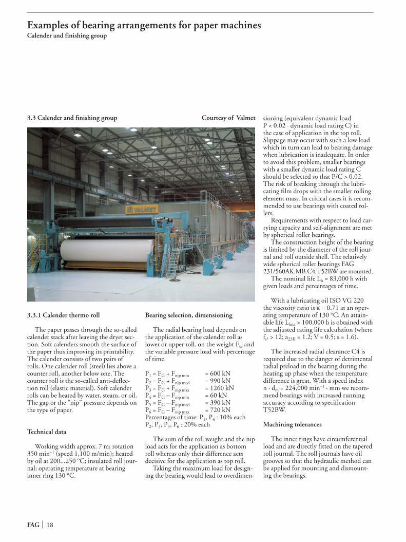
3.3 Calender and fin ish ing group Courtesy of Valmet

19 FAG
Examples of bear ing arrange ments for paper machinesCalender and fin ish ing group
Roundness tol er anceIT5/2 (DIN ISO 1101),
taper angle tol er anceAT7 (DIN 7178).
Bearing seats in the hous ing bore accord ing to F7.
Lubrication
Oil cir cu la tion lubri ca tion with a syn -thet ic oil ISO VG 220, suit able in qual -ity, which has stood dynam ic test ing onthe FAG test rig FE8.
By sup ply ing a large amount of oil tothe cen tre of the bear ing (min i mum oilflow rate 12 l/min) heat dis si pa tion is achieved as well as a low ther mal stress ofthe oil. Any con tam i nants or wear par ti -cles are washed out of the bear ing. Oil returns to both sides of the bear ing via oilcol lect ing pock ets and con nect ing holes.
Sealing
Angle rings at the roll side pre vent direct oil escape at the cover holes. Re-maining oil is thrown off via splash grooves into col lect ing cham bers anddirect ed back. Cover seal ings (O-rings)make the hous ing oil proof.
Courtesy of Voith

3.3.2 Spreader roll
Paper webs which are trans port ed inlength wise direc tion tend to devel opcreas es. Spreader rolls stretch or expandin cross direc tion the webs run ning overthem. They flat ten creas es and any mid -dle or end parts of the web. Spreader rollscon sist of a sta tion ary axle which is bentsym met ric to its lon gi tu di nal axis, and around which the roll shell rotates. Tube- shaped sec tions make up the roll shelland are arranged to rotate free ly and haveangu lar free dom. The sec tions adjust toone another in such a way that the bend -ing form of the axle is reflect ed on theshell sur face. Depending on the case ofappli ca tion – wet end sec tion, dryer sec -tion, or fin ish ing/con vert ing – the sec -tions are made of stain less steel or pro vid -ed with a flex ible cover (e. g. rub ber).
Technical data
Roll length 8,300 mm, con sist ing of22 sec tions; weight/sec tion plus wire orpaper web ten sion at 30° wrap angle 2 kN; a radi al load of just 0.5 kN perbear ing results there from. Rotation ofroll shell 1,160 min–1.
Operating tem per a ture in the wet endsec tion 40 °C; in the dryer sec tion and in
fin ish ing with infrared dry ing tem per a -tures can reach up to 120 °C.
Bearing selec tion, dimen sion ing
With rotat ing outer ring, extreme ly smooth run ning is required from thebear ings since the sec tions in the wet endsec tion and in the dryer sec tion or fin ish -ing/con vert ing are only driv en by thewire ten sion and the paper web respec -tive ly.
High oper a tion al reli abil ity is also nec -es sary since the fail ure of one bear ing alone means that the whole spread er rollhas to be dis mount ed.
FAG 61936.C3 deep groove ball bear-ings are mounted. For new high-speedapplications (n · dm values 0.6 to 1 · 106
min-1 · mm) deep groove ball bearingswith ceramic balls (hybrid bearings) areselected. The increased radi al clear anceC3 per mits easy align ment of the sec -tions. With the low load, the bear ingshave a nom i nal life Lh of well over100,000 hours.
Machining tol er anc es
As the outer ring of the bear ing rotateswith the roll shell it is given a tight fit
with M6 tol er ance and is secured axial lyby a snap ring.
The inner ring has point load and isfit ted to the shaft sleeve with h6. Due tothe bent roll axle and for assem bly rea -sons the sleeve is loose ly fit ted and axial lyposi tioned with a bolt.
Lubrication
The bear ings are greased for life, i.e.no relu bri ca tion is pro vid ed for. Theselec tion and fill ing quan tity of lubri cat -ing grease is deter mined by the demandfor smooth run ning as well as a ser vicelife of up to five years (8,000 oper at inghours per year). Low-fric tion greas es (e.g. FAG grease Arcanol L75) are ad-vantageous with high speeds and low loads.
Sealing
Non-rub bing dust shields are used forseal ing due to the smooth run ning required. They are stuck to the bear ingouter ring on both sides so the base oilcen tri fuged from the lubri cat ing greasecan not escape. O-rings also pro vide foroil tight ness.
FAG 20
Examples of bear ing arrange ments for paper machinesCalender and fin ish ing group

FAG ser vice for more oper a tion al reli abil ityStorage of roll ing bear ings · Preparation · Mounting and Dismounting
4 FAG ser vice for more oper a tion al reli abil ity
FAG has a com plete pack age of ser viceequip ment and ser vic es. Working withbear ings is facil i tat ed by FAG meas ur ingand mount ing devic es such as the diag no -sis device which mon i tors the con di tionof the bear ings plus the FAG mount ingand diag no sis ser vice on site when mount -ing and mon i tor ing jobs prove dif fi cult.
Application engi neer ing at FAG pro -vides advice and train ing in rela tion to all aspects of roll ing bear ing tech nol o gy.
4.1 Storage of roll ing bear ings
Rolling bear ings should be left in theirorig i nal pack ag ing until direct ly beforemount ing so as to pre vent con tam i na tionand rust. Large bear ings such as those found in paper machines are stored in asep ar ate dry room in hor i zon tal posi tionwith a sup port around the entire cir cum -fer ence.
Rolling bear ing pack ing includ ing theanti-cor ro sion agent are such that the bearing's prop er ties can be pre served for along peri od. It is ensured that the anti-cor ro sion agent is com pat ible with thelubri cants pop u lar in the paper indus tryand it is not required to be washed outprior to mount ing.
During stor age, bear ings must not besub ject to any agres sive media such as gases, mist, or aero sols of acids, caus ticsolu tions and salts. Direct sun light mustalso be avoid ed as large fluc tu a tions intem per a ture may arise in the pack ag ing.
Under stan dard pres er va tion con di -tions the per mis sible stor age peri od is upto 5 years. FAG pro vides upon requestinfor ma tion on spe cial pres er va tion andthe usabil ity of older bear ings.
Please refer to the cat a logue WL 41 520 "FAG Rolling Bearings" formore detailed infor ma tion on the stor ageof FAG roll ing bear ings and greas es.
4.2 Preparations for mount ing and dis mount ing
The nec es sary prep ar a tion for mount -ing and dis mount ing roll ing bear ings ispre sent ed in detail in the FAG pub li ca -
tion WL 80 100 "Mounting and Dis -mounting of Rolling Bearings".
Prior to unpack ing the bear ings allmat ing parts required should be checkedfor their dimen sion al and form accu ra cy.
An out side microm e ter is gen er al lyused to check the shaft seats of larg erbear ings.
An inside microm e ter or bore meas ur -ing devic es are used to check the hous ingbores.
Checking a hous ing bore with an inside microm e ter
4.3 Mounting and dis mount ing with cylin dri cal and tapered mat ing sur fac es
General infor ma tion on mount ingand dis mount ing roll ing bear ings is pro -vid ed in the FAG pub li ca tion WL 80 100"Mounting and Dismounting of RollingBearings".
Thermal and hydraul ic meth ods areusu al ly used for mount ing bear ings in thepaper indus try.
4.3.1 Mounting and dis mount ing with cylin dri cal mat ing sur fac es
Mounting: Bearings which require atight fit on a cylin dri cal shaft are heat edup and then shrunk on. For the mostcomm mon fits (cf. sec tion 4.4) a tem per -a ture of 80 to 100 °C suf fic es for heat ingup. The per mis sible max i mum mount ingtem per a ture of 120 °C must not beexceed ed in order to avoid chang es indimen sions and a reduc tion in hard ness.
Induction heat ing devic es allow speedy, clean and safe heat ing. The FAGheat ing device AWG 3,5 (com pare alsoTI No. WL 80-47) is suit able for roll ingbear ings with 20 mm bore or more andweigh ing up to 40 kg.
FAG induc tion heat ing deviceAWG 3,5
Rolling bear ings of all sizes and typescan also be heat ed in oil baths. Disadvan-tage: acci dent haz ard, pol lu tion of theenvi ron ment by oil vapours, inflam -mabil ity of hot oil, dan ger of bear ingcon tam i na tion, expen sive dis po sal ofused oil. The heat ed bear ing parts aremoved to the stop quick ly and with outtilt ing. After pushed on, the inner ring is clamped on and held until cold.
Large bear ings are usu al ly trans port edby crane. The bear ing is then sus pend edin a mount ing tongs.
Dismounting: Mechanical extrac torsor hydraul ic press es are suit able for with -draw ing small er bear ings.
During dis mount ing, inner rings should only be heat ed up with the ringburn er in emer gen cy cases when there areno oil grooves and holes for the hydraul icmeth od. Utmost care must be given asthe rings are sen si tive to non-uni formheat ing and local over heat ing.
Bearings can also be pressed off cylin -dri cal seats by means of the hydraul icmeth od (see sec tion 4.3.2).
21 FAG

FAG ser vice for more oper a tion al reli abil ityMounting and dis mount ing
4.3.2 Mounting and dis mount ing with tapered mat ing sur fac es
Mounting: Rolling bear ings in paper machines are now a days most ly mount eddirect ly on tapered jour nals. Large andwide machines with a high paper speed require high run ning accu ra cy. The directseat is advan ta geous since there are onlytwo mat ing sur fac es.
When run ning accu ra cy require mentsare not so high adapt er or with draw al sleeves are used where by four mat ing sur -fac es are involved.
The required tight fit is achieved bypress ing on the inner ring or press ing inthe with draw al sleeve between inner ringand shaft. The reduc tion in radi al clear -ance due to expan sion of the inner ringindi cates wheth er a suit able tight fit hasbeen reached.
The radi al clear ance is first meas uredprior to mount ing. While press ing on,the clear ance is checked con stant ly untilthe required value is achieved. It is alsopos sible to meas ure axial dis place ment inplace of meas ur ing the reduc tion in radi alclear ance.
Feeler gaug es are used to meas ure theradi al clear ance. It must be ensured thatthe radi al clear ance is meas ured over bothrows of roll ers at the same time in thecase of spher i cal roll er bear ings. Onlywhen the clear ance val ues at both rowsare the same can it be cer tain that the inner ring is not lat er al ly dis placed inrela tion to the outer ring.
The radial clearance of large sphericalroller bearings (d > 500 mm) is measuredat three points because of the ring defor-mation, see scheme.
Hydraulic nuts are used for press inglarge-size bear ings onto the tapered seator for press ing in the with draw al sleeves.Please see also publ. no. WL 80 103"FAG Hydraulic Nuts". The nut is screwed onto the shaft thread or sleeve thread. While press ing in oil, the annu larpis ton press es the bear ing onto the tapered seat or sleeve between bear ingbore and shaft.
If the radial clearance cannot be mea-sured with feeler gauges, the FAG displa-cement measuring instrument RKP.MGcan be used. It is screwed to the face ofthe hydraulic nut.
Hydraulic nuts
The hydraul ic meth od great ly facil i -tates the mount ing and par tic u lar ly thedis mount ing of bear ings with a bore ofabout 160 mm or more. Oil grooves andholes as well as con nec tion threads forpres sure gen er a tors must, how ev er, bepro vid ed. Please refer to FAG publ. no.WL 80 102 "How to Mount and Dismo-unt Rolling Bearings Hydraulically" formore infor ma tion.
Oil with a vis cos ity of ≈ 75 mm2/s at20 °C (nom i nal vis cos ity 32 mm2/s at 40 °C) is rec om mend ed for mount ing.Only a lit tle oil is required when thebear ing seat is direct ly on the taperedjour nal. Simple oil injec tors with low vol -ume suf fice.
Large-size adapt er or with draw al sleeves ( designs HG or H, see cat a logueWL 41 520) have oil inlet holes and oil grooves for the hydraul ic meth od. The oilloss aris ing at the edges of the mat ing sur -fac es make a great er oil sup ply nec es saryand a pump must be used.
The hydraul ic meth od is par tic u lar lyadvan ta geous when dis mount ing large-size bear ings. As soon as a con tin u ous oilfilm has formed between the mat ing sur -fac es the bear ing ring is released abrupt lyfrom the shaft due to the result ing axialforce. An axial stop should be pro vid ed inorder to pre vent acci dents.
Simple oil injec tors with low vol umesuf fice for dis mount ing bear ings whichare direct ly on the tapered jour nal where -as a pump is required when the sleeves arefas tened on.
Oil with a vis cos ity of ≈ 150 mm2/s at20 °C (nom i nal vis cos ity 46 mm2/s at 40 °C) is rec om mend ed for dis mount ing.If the mat ing sur fac es are dam aged a gearoil with high vis cos ity with≈ 1,150 mm2/s at 20 °C (nom i nal vis cos -ity 320 mm2/s at 40 °C) can be used.Fretting cor ro sion can be dis solved byadd ing rust-remov ing addi tives to the oil.
FAG 22
Measuring the radial clearance of large spherical roller bearings
a
b c
ebec
eaeceb
eaa
b c
a
b c
ea
ec=ea
2
eb= ea
2
Messung ohne Prisma
Welle
Messung mit Prisma
Radialluft e =ea + eb + ec
2
measuring with V block measuring without V block
Shaft
radial clearance e =ea + eb + ec
2

FAG ser vice for more oper a tion al reli abil ityFits and tol er anc es
4.4 Fits and tol er anc es
General guide lines on select ing thecor rect fit can be found in the FAG Cata-logue WL 41 520.
The G7 tol er ance is com mon ly usedfor the hous ing bore; paper machinehous ings of the series PM30, PMD,PMDR and PMF are machined accord -ing to G7, for exam ple.
In the case of tapered jour nals the ta-per diam e ter must be deter mined so thatthe bear ing is at the right spot on theshaft once pressed on. When deter min ingthe taper diam e ter – the ref er ence dimen -sion is the small diam e ter – the expan sionnec es sary to obtain a tight inner ring fitmust be taken into con sid er a tion. Thisradi al expan sion of the inner ring de -creas es the radi al clear ance of the bear ing.It must be borne in mind that even withsolid steel shafts, the radi al clear ance isnot reduced by the entire amount ofinter fer ence of the tapered seat. Evensmall er amounts of expan sion result withhol low shafts and shafts made of castiron. In such cases the taper diam e termust be accord ing ly larg er. The dimen -sion al tol er anc es of the bear ings and themachin ing tol er anc es of the shaft mustalso be taken into account. The axial dis -place ment is appro pri ate ly based on thechang es in dis tance between the face ofthe taper at the small diam e ter and theinner ring. The fol low ing tables indi catethe rec om mend ed dimen sion al and formtol er anc es.
Tolerances of tapered shaft seats
23 FAG
Nominal dimension Dia Roundness tolerance Straightnessof shaft tolerance (IT5)/2 tolerance
k6 DIN ISO 1101 IT3over to min maxmm μm μm μm
80 120 +3 +25 7.5 6120 180 +3 +28 9 8180 250 +4 +33 10 10250 315 +4 +36 11.5 12315 400 +4 +40 12.5 13400 500 +5 +45 13.5 15500 630 0 +44 14.5 (17)630 800 0 +50 16 (19)800 1000 0 +56 18 (21)
(val ues in brack ets accord ing to FAG)
Tolerances of taper angle
Nominal dimension Taper angle tolerance acc. AT7 (DIN 7178)of bearing width Bover to ATα ATDmm angular seconds μm
40 63 +65 0/+12.5...0/+2063 100 +52 0/+16...0/+25100 160 +41 0/+20...0/+32160 250 +33 0/+25...0/+40250 400 +26 0/+32...0/+50
ATD/2ATDAT
�
t1
t5t6
The stop area for the taper measuringdevice and the taper OD must bemachined in one setting
A
t1
t5
t6
A
d'
B
L
�
�2
Taper 1:12
Taper 1:30
ATD/2
dd1

FAG ser vice for more oper a tion al reli abil ityFits and tol er anc es
Calculation of small taper diam e ter with roll jour nals
d' = d + ΔR · 1/(dm/h) · 1/fi · w + G'+ Δdmp/2+ L · 1/k [mm]
d' Small taper diam e ter of jour nal [mm]d Nominal bear ing bore diam e ter [mm]ΔR Mean value of radi al clear ance reduc tion (table 1) [mm]dm/h Wall thick ness ratio of inner ring (table 2)1/fi Correction fac tor for steel hol low jour nals (dia gram 3)
= 1 for solid shaftsw Correction fac tor for dif fer ent jour nal mate ri als
(dia gram 4)G' Smoothing value in rela tion to diam e ter = 2 · 0.6 · Rz (table 5) [mm]Δdmp Tolerance of nom i nal bear ing bore diam e ter (table 6) [mm]L Distance between face of mount ed bear ing and of jour nal [mm]
(stan dard case: face of mount ed bear ing abuts with face of jour nal, e. g. L = 0)
1/k Taper ratio (= 0.0833 for taper 1:12/ = 0.0333 for taper 1:30)
Table 1: Radial clear ance reduc tion ΔR
Nominal bore diameter Radial clearance reductiond spherical roller bearings cylindrical roller bearingsover to min max min maxmm mm mm
50 65 0.03 0.04 0.03 0.03565 80 0.04 0.05 0.035 0.0480 100 0.045 0.06 0.04 0.045100 120 0.05 0.07 0.045 0.055120 140 0.065 0.09 0.055 0.065
140 160 0.075 0.1 0.06 0.075160 180 0.08 0.11 0.065 0.085180 200 0.09 0.13 0.075 0.095200 225 0.1 0.14 0.085 0.105225 250 0.11 0.15 0.095 0.115
250 280 0.12 0.17 0.105 0.125280 315 0.13 0.19 0.115 0.14315 355 0.15 0.21 0.13 0.16355 400 0.17 0.23 0.14 0.17400 450 0.2 0.26 0.15 0.185
450 500 0.21 0.28 0.16 0.195500 560 0.24 0.32 0.17 0.215560 630 0.26 0.35 0.185 0.24630 710 0.3 0.4 0.2 0.26710 800 0.34 0.45 0.22 0.28
800 900 0.37 0.5 0.24 0.31900 1000 0.41 0.55 0.26 0.34
Table 2: Wall thick ness ratiofor inner rings where d > 50 mm
Bearing series dm/h
Spherical roll er bear ings
239 0.91230 0.88231 0.85
232 0.83240 0.88241 0.87
222 0.84223 0.78
Cylindrical roll er bear ings
NU10 0.87NU2 0.85NU3 0.78
NU4 0.73NU30 0.89
FAG 24
L
d' dmh di

Diagram 4: Correction fac tor w for dif fer ent mate ri alsGG = grey cast iron; GGG = spheroidal graphite cast iron; St = steel
FAG ser vice for more oper a tion al reli abil ityFits and tol er anc es
Diagram 3: Correction fac tor 1/fi for hol low jour nals (steel) Table 5: Smoothing value G' in rela tion to diam e ter
Machining SmoothingG'mm
polished 0
very finely ground 0.001
ground 0.0025
very finely turned 0.005
finely turned 0.007
Table 6: Tolerance Δdmpof bear ing bore
Nominal bore Tolerancediameterover tomm μm
50 80 0/+30
80 120 0/+35
120 180 0/+40
180 250 0/+46
250 315 0/+52
315 400 0/+57
400 500 0/+63
500 630 0/+70
630 800 0/+80
800 1000 0/+90
25 FAG
0 0.1 0.2 0.3 0.4 0.5 0.6 0.7 0.9
1.0
1.2
1.4
1.6
1.8
2.0
dm/h=0.7
0.8 0.9
di/dm
1/fi
0.8
0 0.1 0.2 0.3 0.4 0.5 0.6 0.7 0.9
1.0
1.05
1.10
1.15
1.20
1.25
1.30
1.35
St
GGG
GG
w
0.8
di/dm

FAG ser vice for more oper a tion al reli abil ityMonitoring and ana lys ing bear ings
4.5 Monitoring and ana lys ing bear ings
Rolling bear ings in paper machinesmust be mon i tored in order to avoid high repair costs and lost pro duc tion. The ser -vice life of the bear ings and the avail abil -ity of the machine can be opti mal ly usedonly when the bear ings are main tained inrela tion to their con di tion. This pre sup -pos es, how ev er, rec og ni tion of bear ingdam age on time, eval u a tion of the extentof dam age and devel op ment of the progress in dam age. Condition-relat edmain te nance means that the bear ing canbe replaced dur ing a sched uled stop ofthe machine, thus avoid ing unnec es sarydown time.
4.5.1 FAG Detector 2000
The FAG Detector is main ly of inter -est for bear ings in the periph er als of paper machines where hard ly any dis -turb ing influ enc es by other machineparts are expect ed.
The handy, cost-effec tive meas ur ing device, is easy to use with just eight keys.First the accel er a tion sen sor is attached tothe bear ing loca tion to be mon i tored.
First, the acceleration sensor has to beattached to the bearing location to bemonitored. After a round of taking mea-surements, the measured values that areused to evaluate the condition of machineor component are transferred to a com-
puter where they are interpreted, analysedand displayed graphically by the software”FAG 2000”.
For every measuring point the softwarecompares the newly measured values withthe alarm-triggering limiting values speci-fied for this measuring point. If one ofthese threshold values is exceeded this isindicated by the software.
Newly added values can be displayedgraphically versus the measuring time.
Trend analyses help users to assesswhen an alarm is likely to be triggered.
More detailed information on the De-tector 2000 will be provided on request.
4.5.2 FAG Bearing Analyser 2000
An effi cient dam age diag no sis systembased on enve lope detec tion has been oneof the numer ous FAG ser vic es for manyyears. Operators have the oppor tu nity ofpur chas ing the Bearing Analyser diag no -sis device from FAG with which they canper ma nent ly mon i tor the con di tion oftheir plants them selves.
The first hint of bear ing dam age isgen er al ly given by chang es in vibra tion.They are reg is tered and eval u at ed by theFAG Bearing Analyser. The handy anduser-friend ly vibra tion anal y ser func tionsaccord ing to the long-prov en enve lope
detec tion meth od. It diag nos es all dam- age which caus es noise, e.g. cracks, pit -tings, inden ta tions or dirt. The accel er a -tion sen sor con nect ed to the port able device meas ures vibra tions up to 20 kHz.
Once cur rent speed and bear ing datahave been entered, the expert system eval -u ates them and dis plays to the user with ahigh degree of reli abil ity wheth er or notthe bear ing is dam aged. The high er the progress of dam age, which can be deter -mined by means of trend meas ure ments,the more fre quent the mon i tor ing beforebear ing exchange is a must.
More detailed information on the”FAG Bearing Analyser” will be providedon request.
4.5.3 VibroCheck system
FAG's online mon i tor ing system “VibroCheck” allows a large num ber ofmeas ur ing loca tions to be mon i toredcon tin u ous ly with the PC. Vibrationsen sors at the bear ing loca tion con ductsig nals to mon i tor ing mod ules (VCmod ules). The sig nals are trans ferred viaPC to the con trol sta tion of a paper millor per modem to an FAG ser vice sta tionif required. When a warn ing limit hasbeen reached, an expert system makes an auto mat ic diag no sis with the same degree of reli abil ity as the anal y ser (sec -tion 4.5.2).
FAG 26
FAG VibroCheck
FAG Bearing Analyser 2000FAG Detector 2000

FAG ser vice for more oper a tion al reli abil ityMonitoring and ana lys ing bear ings
4.5.4 Bearing anal y sis
The cause of dam age and the pos sibil -ity of avoid ing more fail ures in the futuremust be clar i fied when a dam aged bear -ing is dis mount ed from a machine. Thebear ing must be sent for inspec tion to
FAG if the cause of fail ure can not bedeter mined by either the oper a tor of thepaper machine or an FAG rep re sen ta tiveon the spot.
The fol low ing data must be pro vid edwhen return ing dam aged bear ings:
Pressure pol ished race way and first stag esof wear in the outer ring of a spher i calroll er bear ing; mount ed at the operator'send of a dryer roll. Cause: amount ofwater in lubri cat ing oil too high.
Slippage dam age on a bar rel roll er of aspher i cal roll er bear ing; mount ed in asuc tion roll. Cause: too low load andunsuit able lubri cat ing grease
Static cor ro sion in the outer ring race -way of a spher i cal roll er bear ing. Cause: amount of water in lubri cat ing greasetoo high
27 FAG
1. Company Name, Address, Dept.
2. Application
2.1 Machine
2.2 Exact mount ing loca tion (e.g. guide roll, dryer sec tion,locat ing or float ing bear ing)
2.3 Machine man u fac tur er
2.4 Service peri od
2.5 Machine data (prod uct, length, width)
2.6 Number of pre vi ous bear ing fail ures at this loca tion/sec tion
3. Operating con di tions - roll diam e ter- paper speed- roll length- rota tion- radi al (axial) load- daily run ning peri od- lubri ca tion (type, oil type, grease type, quan tity, relu bri ca tion inter val)- draw ing of bear ing loca tion(fits, seal ing etc.)
4. Bearing - code (with all suf fix es)- life until fail ure (mount ed when?)- mount ed by whom?- appear ance of dam aged bear ing (inner ring, outer ring, roll ers, cage) pho tos and sketch es if avail able
- how was the dam age rec og nised?
Detailed infor ma tion on fail ure anal y sis and inspec tion of used bear ings can be foundin FAG publ. no. WL 82 102 "Rolling Bearing Damage"

FAG ser vice for more oper a tion al reli abil ityPC pro grams · Mounting ser vice · Training
4.6 PC pro grams for cal cu lat ing and design ing roll ing bear ings
The strive towards more oper a tion alreli abil ity com menc es long before bear -ings are mount ed. The selec tion of thecor rect bear ing is always the first step.
The FAG cat a logue on CD ROM is afar more effi cient means of select ing andcal cu lat ing roll ing bear ings than the ac tu al print ed book itself. The user has acom plete con sult ing system which leadshim or her – with Windows user guid -ance – to the list of FAG stan dard bear -ings ready for order. Both the nom i nallife and the adjust ed life can be cal cu lat edas well as per mis sible speed, cycling fre -quenc es (impor tant for bear ing diag no -sis), heat bal ance and required oil vol -ume.
With the version 2.0 of the catalogueon CD ROM a DXF file of the selectedbearing can be generated and importedinto CAD drafting programs. Completepages with bearing tables can be printed,also the performance data, the dimensionplan and the abutment dimensions of sin-gle bearings.
FAG also supplies numerous specialcalculation programs. The following canbe calculated for example:– chang es in bear ing clear ance– bear ing elas tic ity and rigid ity – shaft bend ing.Please refer to TI no. WL 49-41 for moreinfor ma tion on these PC pro grams.
4.7 FAG mount ing ser vice
Upon request, FAG fit ters/Service Engineers mount all bear ings in the paperindus try, check mat ing parts (roll jour -nals, hous ings), search for faults whenbear ings are not run ning per fect ly, dis -mount bear ings, train main te nance staff
and pro vide advice on ration al isa tionmeas ures for mount ing pro ce dures. Fit-ters/Service Engineers also assist whenselect ing suit able tools and show users theequip ment and pro cess es involved.
4.8 FAG train ing cours es
A good stan dard of tech ni cal knowl -edge helps to increase the ser vice life ofbear ings and to avoid fail ures.
For years now, FAG has pro vid ed prac -ti cal train ing, cours es and sem i nars onthe theme of roll ing bear ings. They areheld at FAG, at FAG dis trib ut ing partners', and direct ly in the paper mills.Seminars on the spot are advan ta geous inthat the par tic i pants save both trav el lingexpens es and the time get ting there andback.
Training modules for paper mills are:- Basic bearing seminars- Mounting and dismounting training- Lubrication guidelines- Damage analysis seminars- Tailor-made in-house seminars
FAG train ing
FAG devel oped the Software W.L.S.with inter ac tive pro gram guid ance forlearn ing alone at the com put er. Thislearn ing pro gram con veys solid basicknowl edge on the prop er ties of the diverse bear ing types, the system of cod -ing, on mount ing bear ings and avoid ingbear ing dam age. The dia logue-orient edlearn ing pro gram takes more and moreindi vid u al train ing and fur ther train ingin com pa nies into con sid er a tion. Thecom plete soft ware pack age is suit able forall those involved with roll ing bear ingswheth er in Purchasing or Materials Management, Designing and Develop-ment or in Maintenance.
FAG roll ing bear ing learn ing systemW.L.S.
Several FAG video films are avail ablefor train ing, instruc tion, and ser vice,such as:– mount ing and dis mount ing roll ing
bear ings– hydraul ic meth od for mount ing and
dis mount ing large roll ing bear ings– induc tion heat ing device for mount -
ing large roll ing bear ings– bear ing replace ment with FAG split
spher i cal roll er bear ings 222SM.
Please see TI no. WL 00-11 for more films.
FAG 28

FAG ser vice for more oper a tion al reli abil ityA selec tion of pub li ca tions
4.9 A selec tion of other FAG pub li ca tions
CatalogueWL 41520 FAG Rolling Bearings
Publ. No.WL 13 111 Self-aligning Cylindrical Roller Bearings for Dryer Rolls/M.G. Cylinders and Guide Rolls of Paper MachinesWL 13 112 A Partnership in PaperWL 13 501 Bearing arrange ment of an M.G. cyl in der of a paper mak ing machineWL 13 502 FAG Spherical Roller Bearings in a Wood GrinderWL 13 503 FAG E spher i cal roll er bear ings in felt guide rolls in the dryer sec tion of paper mak ing machinesWL 13 504 Increased capac ity of a Finnish paper mak ing machineWL 13 505 Refiner Bearings Arrangement with FAG Cylindrical Roller BearingsWL 13 506 Creping cyl in der bear ings in a tis sue paper mak ing machineWL 13 507 Increasing the Output of Papermaking Machines by Converting the Dryer Section to FAG Rolling BearingsWL 13 508 FAG split spher i cal roll er bear ings in dryer roll ers of paper mak ing machines reduce down times for bear ing
replace mentWL 13 509 FAG deep groove ball bear ings for spread er rolls in paper mak ing machinesWL 13 510 Considerable ener gy reduc tion by con ver sion of dryer rolls in paper mak ing machines from slid ing bear ings to
roll ing bear ingsWL 13 511 Dryer Roll Bearings have worked reli ably in a Finnish Cardboard Mill for more than 10 yearsWL 13 512 FAG Split Spherical Roller Bearings in Paper Mill Agitators Reduce DowntimeWL 13 513 FAG Hybrid Bearings for Spreader RollsWL 13 514 FAG Self-Aligning Ball Bearings for Fly Rolls in CalendersWL 43 165 FAG Split Spherical Roller BearingsWL 80 100 Mounting and Dismounting of Rolling BearingsWL 80 102 How to Mount and Dismount Rolling Bearings HydraulicallyWL 80 103 FAG Hydraulic NutsWL 80 137 Rolling bearing diagnosis with the FAG bearing detectorWL 80 141 Rolling bearing diagnosis with the FAG bearing analyserWL 80 151 Repair service for large rolling bearingsWL 81 115 Rolling Bearing Lubrication WL 82 102 Rolling Bearing Damage
TI No.WL 13-1 Housings for Dryer Rolls in Paper-Making MachinesWL 13-2 PMF Housings for Guide Rolls in Paper MachinesWL 43-1192 FAG Triple Ring Bearings for the Paper-Making IndustryWL 49-41 PC Calculation ProgrammesWL 62-1 “Doping” for the SurfaceWL 80-14 Mounting and Dismounting of Spherical Roller Bearings with Tapered BoreWL 80-46 FAG Hand Pump Sets WL 80-47 FAG Induction Heating DevicesWL 80-48 FAG Mechanical Extractors
29 FAG

Dimensioning and lubri cat ing roll ing bear ingsDimensioning
5 Dimensioning and lubri cat ing roll ing bear ings
5.1 Dimensioning
Rolling bear ings are checked for meet -ing demands on life and cost-effi cien cyby means of the dimen sion ing cal cu la -tion. Bearings in paper machines aredynam i cal ly stressed as a rule. The ringsof such bear ings rotate rel a tive to one another.
The cal cu la tion of the nom i nal life Lhfor dynam i cal ly stressed bear ings is pro -vid ed in detail in the cat a logue WL 41 520 "FAG Rolling Bearings". Ofthe oper at ing con di tions only the loadand the speed are taken into account withthis pro cess. The attain able life real ly depends, how ev er, on a num ber of otherinflu enc es.
Based on the adjust ed life cal cu la tionaccord ing to DIN ISO 281, FAG devel -oped a refined pro cess to deter mine theattain able life Lhna with which the oper at -ing con di tions, par tic u lar ly the clean li -ness effect in the lubri cat ing gap, can be expressed in fig ures. The pro cess for cal -cu lat ing the attain able life is described inthe cat a logue WL 41 520.
Recommended val ues for dimen sion ing
Reccommended val ues for the attain -able life Lhna are indi cat ed in the fol low -ing table for the var i ous mount ing loca -tions in machines and equip ment used inthe pro duc tion of paper. The Lh life val -ues reached so far are also pro vid ed forrea sons of com par i son. They large ly cor -re spond to the rec om men da tions madeby TAPPI (Technical Association of thePulp and Paper Industry, USA). As anexam ple a rec om mended value for Lh of285,000 hours is indi cat ed for dryer rolls.For old non-insu lat ed jour nal bear ingarrange ments an attain able life Lhna of about 100,000 hours results where fac tora23 = 0.35. In mod ern machines withstan dard jour nal insu la tion an Lhna value
of more than 250,000 hours is expect ed,an unusu al ly high ser vice life.
In con trast, the ser vice life expec ta tionfor bear ings in the wet end sec tion is wellbelow 15 years as chang es and mod ern -iza tions are com mon with in this time.
Enormous dif fer enc es in oper at ing speeds as in the case of dryer rolls forexam ple, play an impor tant role whendesign ing. They are less than 800 m/minfor board machines and up to 1,800 m/min for dryer rolls for news - pa per machines.
Recommended val ues for dimen sion ing roll ing bear ings found in paper pro duc tion
Application AttainablelifeLhna*)h years**)
Wet section
forming rolls,suction rolls,guide rolls, > 100 000 > 12press rolls
Dryer section (basic demand: Lh > 100 000 h)
guide rolls > 120 000 > 15
dryer rolls > 250 000 > 30
M.G. Yankee cylinders > 350 000 > 45
Other parts
calenders,glazing rolls, > 80 000 > 10reel spool bearings
anti-deflection rolls > 80 000 > 10
refiners,pulpers > 80 000 > 10
*) cal cu lat ed with a23 = a23II, i.e. s = 1 for nor mal clean li ness**) at 8,000 oper at ing hours per year
We rec om mend deter min ing first Lhfor the roll with the high est load tak ingthe design speed (nD) into con sid er a tionand the equiv a lent dynam ic load P (seepage 31).
The real oper at ing speed and thus thelow est vis cos ity ratio κ should be takeninto con sid er a tion for cal cu lat ing the Lhnavalue.
Please see ref er ence val ues in dia gramon the page 31 for the oper at ing tem per a -ture of dryer roll bear ings (inner ring).
FAG 30

Dimensioning and lubri cat ing roll ing bear ingsDimensioning
Equivalent dynam ic load P of bear ingsin paper machines
G weight of roll/cyl in der [kN]
Fz felt pull/wire pull [kN]at 180° wrap angle
f1 = 1.055 for tem po rary fill ing of dryer and M.G./Yankee cyl in ders with con den sa tion water
f2 = 1.1 for axial forc es act ing on locat ing bear ing(drive, pull of oblique felt or wire), when val ues are not avail able
Dryer / M.G./Yankee cyl in der, operator's end:
P = (G/2 + Fz) · f1addi tion al ly: axial dis place ment forcewith spher i cal roll er bear ing as float ingbear ing and force from steam joint,with M.G./Yankee cyl in der relief bymeans of pres sure rolls
Dryer / M.G./Yankee cyl in der, driveend:
P = (G/2 + Fz) · f1 · f2addi tion al ly: radi al force from driveand force from steam joint and axialdis place ment force of float ing bear ing
Guide rollP = (G/2 + Fz) · f2
Suction roll:P = (G/2 + Fz) · f2addi tion al ly: force direc tion as well as relief or load due to neg a tive pres surein suc tion box
Press roll/pres sure roll:P = (G/2 + Fz) · f2addi tion al ly: force direc tion as well as relief or load due to other rolls/cyl in -ders
Calender roll:P = G/2 + FNip/2addi tion al ly: posi tion of appli ca tion,time and load shares (cf. also sec tion3.3.1)
Correction fac tor for reduc tion in hard ness
Under oper at ing tem per a tures > 100 °Cthe dynam ic load rat ing C must be mul ti -plied by fH for bear ings in paper ma -chines which are heat-treat ed to S1 inaccor dance with stan dard.
Correction fac tor fH for con sid er a tion ofoper at ing tem per a ture effect on the loadrat ing of bear ings made of chro mi umsteel
Reference val ues for the tem per a ture of bear ings in dryer rolls, valid for pop u larspher i cal roll er bear ing sizes lubri cat ed with min i mum oil flow rates (sec tion 5.2.2),depend ing on steam tem per a ture and insu la tion (cor re la tion steam tem per a -ture/steam pres sure see 6.1.3 and 6.1.4)
31 FAG
0 100 200
1.1
1.0
0.9
temperature°C
fH
0.8
meantemperaturebearinginner ring
70
80
90
100
110
120
130
140
150
°C
140 150 160 170 180
roll journal insulated
roll journal not insulated
steam temperature
ºC

Dimensioning and lubri cat ing roll ing bear ingsLubrication
5.2 Lubrication of roll ing bear ings
The oper at ing con di tions and the con -se quent demands on lubri ca tion can dif -fer great ly from one bear ing loca tion to another in paper machines. For this rea -son lubri ca tion is dealt with in sec tion 3under bear ing exam ples. Here, just gen er -al views on the lubri ca tion of roll ingbear ings in paper machines are pre sent ed.Rolling bear ing lubri ca tion is pre sent edin detail in the FAG pub li ca tion WL 81 115 "Rolling Bearing Lubrication".
Load, speed and oper at ing tem per a -ture of the bear ing as well as envi ron men -tal con di tions and oper a tion al reli abil ityare deci sive for the choice of lubri ca tion system. As a result oil cir cu la tion lubri ca -tion is gen er al ly select ed for bear ings inmod ern paper machines where as greaselubri ca tion is sel dom con sid ered.
Heat bal ance cal cu la tions are some -times of use in order to cal cu late the lossin bear ing effi cien cy (see publ. no. WL81 115). How cor rect such a cal cu la tionis depends on pre vi ous knowl edge ofoper at ing data and cor re spond ing val uesfor heat flow con di tions.
5.2.1 Grease lubri ca tion
Grease lubri ca tion is pos sible for smalland mid dle-size bear ings if speed andtem per a tures are not too high. Greaselubri ca tion is advan ta geous in that thecon struc tion is not com plex and the grease also pro vides for seal ing. Mainten-ance is also sim ple. The remain ing ser vicelife can be long er when there is a break -down in lubri cant sup ply. In the case ofbear ings in paper machines grease lubri -ca tion is main ly used for those in the wetend sec tion as tem per a tures are low andseal ing against water and con tam i na tionmust be kept in mind.
Grease-lubri cat ed bear ings in the dryersec tion where tem per a tures are high andbear ing loca tions are under great stressare an excep tion.
Selection of grease
You will find cri te ria for select ing grease in the FAG pub li ca tion num berWL 81 115, for exam ple.
Along with the data on grease prop er -ties pro vid ed by the grease man u fac tur er,expe ri ence in the field of grease appli ca -
General rec om men da tions for the grease lubri ca tion of bear ings in paper machines(wet end sec tion and dryer sec tion)
• Greases accord ing to FAG's out line of require ments (see pg. 33)
• Direct grease sup ply (for exam ple with spher i cal roll er bear ingsvia lubri cat ing groove and holes in the outer or inner ring)
• Weekly – month ly relu bri ca tion depend ing on envi ron men tal effects
• Relubrication quan tity accord ing to FAG publ. no. WL 81115/4, pg. 38m1 = 0.002 · D · B [g] with man u al grease sup plym2 = 1 · [π/4 · B · (D2 – d2) · 10–9 – G/7800] [kg/h] with
auto mat ic grease sup ply systems
with D bear ing out side diam e ter [mm]B bear ing width [mm]d bear ing bore [mm]G bear ing weight [kg]
• Grease remov al at both sides
• Plenty of relu bri ca tion prior to and fol low ing down time
• Avoid mix ing dif fer ent greas es if pos sible, even if com pat ibil ity is indi cat ed
• Install short sup ply pipes
• Protect sup ply pipes from heat
tion are of par tic u lar impor tance. As a result, FAG drew up an out line of re -quire ments and spec ifi ca tions for thedryer sec tion and the wet end sec tion sep -ar ate ly. You can receive upon request anupdat ed list of greas es rec om mend ed byFAG for the wet end sec tion and thedryer sec tion.
FAG 32

Dimensioning and lubri cat ing roll ing bear ingsLubrication
Requirements on greas es for bear ings in the wet end sec tion:
– very good water resis tance– good seal ing effect– very good anti-cor ro sive prop er ties– good lubri cat ing film for ma tion prop er ties– good com pat abil ity with elas to mers and plas tics– multi-metal com pat ibil ity– good oxi da tion stabil ity– excel lent lubric ity also in bear ings with com plex kin e mat ics by means of a select ed
thick en er and EP addi tives which are effec tive in the most diverse bear ing types– high degree of clean li ness– good con vey ance in cen tral lubri cat ing systems
(no sep ar a tion of oil and thick en er under pres sure, good decom pres sion char ac ter -is tics, good pump abil ity beha vi our in stor age con tain ers)
Requirements on greas es for bear ings in the dryer sec tion:
– excel lent oxi da tion stabil ity– very good suit abil ity to high tem per a tures– no devel op ment of res i dues/depos its in bear ings and hous ings– very good anti-cor ro sive prop er ties– multi-metal com pat ibil ity– good lubri cat ing film for ma tion prop er ties– excel lent lubric ity also in bear ings with com plex kin e mat ics by means of an effi -
cient thick en er and effec tive addi tives in bear ings at most diverse tem per a tures– good seal ing effect – good com pat ibil ity with elas to mers and plas tics– high degree of clean li ness– easy con vey ance in cen tral lubri cat ing systems
(no sep ar a tion of oil and thick en er under pres sure, good decom pres sion char ac ter -is tics, good flow ing beha vi our in stor age con tain ers, no cok ing in pipes)
– good grease escape from the hous ing– very long ser vice life
Overall reduc tion fac tors q
Bearing loca tion Overall reduc tion fac tor q
Wet end sec tionpar tial ly very moist envi ron ment 0.1 – 0.3
Dryer sec tionwhere grease lubri cat ed 0.3 – 0.4(e.g. dryer felt guide rolls)
Grease sup ply
The appro pri ate grease quan tity, relu -bri ca tion inter vals based on grease ser vicelife, cor rect design ing of bear ing lubri ca -tion and the suit able mode of lubri ca tionare deci sive for an ade quate lubri cantsup ply. The fun da men tal aspects are dealtwith in detail in the pub li ca tion no. WL 81 115.
The dia gram with lubri ca tion inter valstf shown there is only valid for favour ableenvi ron men tal con di tions and stan dardlith i um soap base greas es. The effect oftem per a ture and the envi ron ment is ofpar tic u lar impor tance in the case of paper machines.
The reduced lubri ca tion inter val tfqwith the over all reduc tion fac tor q (see table, below left) is derived from
tfq = q · tf
which takes into account all adverse oper -a tion al and envi ron men tal con di tions.
The relu bri ca tion inter val of 0.5 to 0.7 · tfq should be taken. Experience hasshown that relu bri ca tion inter vals of ≤ 2weeks and of about 4 weeks suf fice forbear ings in the wet end sec tion (extreme -ly wet loca tions) and for grease-lubri cat edbear ings in the dryer sec tion respec tive ly.
In the case of spher i cal roll er bear ingsthe fresh grease should always be sup pliedvia the lubri cat ing groove and the lubri -cat ing holes in the outer ring to expell theused grease and ensure opti mal grease exchange. A com plete ly even dis tri bu tionon both roll er rows is achieved where bythe used grease is expelled from the bear -ing. This is of par tic u lar impor tance forbear ings in dan ger of cor rod ing in thewet end sec tion. It is not pos sible toreplen ish bear ings dur ing oper a tion witha rotat ing outer ring.
Therefore bear ings with lubri cat ingholes in the inner ring should be usedhere in order to sup ply grease direct ly tothe cen tre of the bear ing. Bearing designswith lubri cat ing groove and holes are re c -om mend ed; with this design a cir cum fe -ren tial lubri cat ing groove on the bear ingjour nal is not nec es sary.
33 FAG

Dimensioning and lubri cat ing roll ing bear ingsLubrication
The effect of such meas ures is fre -quent ly under es ti mat ed. As expe ri encehas shown, the most dam age aris es in the grease-lubri cat ed bear ings of the wet endsec tion due to poor lubri cant sup ply ordilu tion of the lubri cant with water ( reduced lubri cat ing effect) and directcor ro sion at the func tion al areas.
Since cor ro sion can occur dur ing bear -ing down time also (due to pen e tra tion ofwater dur ing clean ing or devel op ment ofcon den sa tion) it is advan ta geous to re -plen ish the bear ings thorough ly direct ly before shut ting down the machine orwhen rolls are put in reserve.
A mix ture of dif fer ent greas es shouldbe avoid ed if pos sible. Greases with dif -fer ent soap bases should not be mixed.Thorough clean ing with flush ing is amust if a dif fer ent grease type is to be applied.
When a new bear ing has been mount -ed relu bri ca tion should be under tak enrel a tive ly soon in order to elim i natemount ing con tam i na tion and run ning-inwear.
5.2.2 Oil lubri ca tion
Oil lubri ca tion is nec es sary when bear -ings are expect ed to heat up very highdue to load and speed and/or due to theirenvi ron ment.
Oil cir cu la tion lubri ca tion pref er ablyused in new paper machin ery has the fol -low ing advan tag es:
Contaminants do not com pile whenthe oil sup ply drain age is cor rect ly designed; they are trans port ed to the cor -re spond ing oil main te nance equip ment(fil ters, sep ar a tors, sed i men ta tion pit etc.)
and removed from cir cu la tion. Oil stressis reduced with a large total oil vol ume.Besides, heat dis si pates with oil cool ingand the bear ing tem per a ture drops.
General rec om men da tions for the lubri ca tion of bear ings in paper machines withcir cu lat ing oils:
• Oils accord ing to the out line of FAG require ments• Direct oil sup ply, via lubri cat ing groove and lubri cat ing holes in the rings of spher i -
cal roll er bear ings and self-align ing cylin dri cal roll er bear ings • Oil exit on both sides with suf fi cient ly dimen sioned drain pipes cross sec tion• Avoidance of resid u al oil sump• Minimum flow rates accord ing to FAG rec om men da tions• Lubrication mon i tor ing of each indi vid u al bear ing loca tion• Protection of sup ply pipes from heat• Oil sup ply tem per a ture of max. 50 – 60 °C by means of oil cool ing for the dryer
sec tion• Separate oil sup ply systems for the dif fer ent sec tions of paper machines• Effective jour nal insu la tion in the case of dryer rolls and ther mo rolls
Note: With the insu la tion of hol low jour nals and an ade quate oil flow rate as wellas recool ing, a low bear ing tem per a ture can be achieved today and thus suf fi cientoper at ing vis cos ity of the lubri cat ing oil. A vis cos ity ratio κ < 0.4 can be antic i pat edwith non-insu lat ed jour nal bores and low speed and there fore a life fac tor a23 of0.35 at a max.
• Settle-down zones and air release facil ities in the tank• Oil main te nance meas ures:
– Rinsing and fine-mesh fil ter ing prior to start ing up, afterbig repair work, bear ing dam age or com plete oil exchange
– Filtering in main stream with 12 μm, bet ter 6 μm, with a fil tra tion ratio of βx ≥ 75. Additional by-pass fil ter ing with 6 μm and βx ≥ 75 increas es effec tiv ity with high flow rates con sid er ably.
– Oil clean li ness class 15/12 accord ing to ISO 4406– Water con tent < 0.03 % weight (300 ppm)– Exchange oil on time depend ing on oil con di tion
(respon sibil ity of the oil sup pli er)
In the case of high ly doped min er aloils and syn thet ic oils com pat ibil ity withseal ing and cage mate ri als should be keptin mind.
FAG 34

Dimensioning and lubri cat ing roll ing bear ingsLubrication
Oil selec tion
Mineral oils and syn thet ic oils are suit -able for lubri cat ing roll ing bear ings. Theselec tion of the oil depends on the oper -at ing con di tions present at the bear ingloca tion.
FAG spec i fies the oil require ment intwo sep ar ate lists for paper machines –one for the wet end sec tion and one forthe dryer sec tion.
Requirements on cir cu lat ing oils for bear -ings in the wet end sec tion:
– high oxi da tion stabil ity– good demul si fy ing abil ity– good anti-cor ro sive prop er ties– multi-metal com pat ibil ity– hydrol y sis stabil ity– high vis cos ity index– high pres sure-vis cos ity coef fi cient– effec tive boun dary layer form ing addi -
tives in roll ing bear ing– good com pat ibil ity with elas to mers
and plas tics– keep clean per for mance– good fil ter abil ity– good com pat ibil ity with pre ser va tives– par tic u lar ly good long-term suit abil ity
Requirements on cir cu lat ing oils for bear -ings in the dryer sec tion:
– best oxi da tion stabil ity– good demul si fy ing abil ity– good anti-cor ro sive prop er ties– multi-metal com pat ibil ity– hydrol y sis stabil ity– high vis cos ity index– high pres sure-vis cos ity coef fi cient– effec tive boun dary layer form ing addi -
tives in roll ing bear ing– good com pat ibil ity with elas to mers
and plas tics
– keep clean per for mance– good fil ter abil ity– anti-foam prop er ties– no res i due/depos it devel op ment and
cloudi ness of the oil– par tic u lar ly good long-term suit abil ity.
You can receive upon request anupdat ed FAG rec om men da tion list of oilsfor both sec tions.
Oil sup ply
The vol ume of oil to be sup plied ineach case depends essen tial ly on the con -di tions regard ing heat elim i na tion andheat sup ply. With a high speed index (n · dm > 300,000 min–1 · mm, e.g. withsuc tion rolls) heat bal ance cal cu la tions asin accor dance with FAG publ. no. WL 81 115/4 are rec om mend ed.
Only a very small oil vol ume is actu al -ly required to lubri cate the bear ing itselfbut far great er vol umes are select ed forsafe ty rea sons and to insure that all con -tact areas have suf fi cient oil. The vol umeincreas es even more if heat dis si pa tion is required.
The advan tage of direct lubri cant sup -ply via lubri cat ing groove and holes inthe rings should be availed of for oil-lubri cat ed bear ings as well.
Rolling bear ings must be lubri cat ed before going into oper a tion. With cir cu -lat ing oil lubri ca tion, this is achieved bystart ing the oil pump before the machineis put into oper a tion. Please refer to thedia grams on pages 36 and 37 for oil flowrates rec om mend ed by FAG for each ofthe bear ing loca tions in a paper machine.
Pressure drop with oil cir cu la tion lubri ca tion
As already described, the oil shouldreach the bear ing as direct ly as pos sible.As a result the cool oil, with no pre vi ousheat ing, is direct ed to the con tact areas tobe lubri cat ed where it heats up and car -ries off heat. The oil has a high er vis cos itydue to the low tem per a ture and a bet terload-car ry ing lubri cat ing film can buildup.
Due to the lubri cat ing grooves in theFAG spher i cal roll er bear ings and dou blerow cylin dri cal roll er bear ings there is adrop in pres sure when the oil vol ume islarge. With a large num ber of bear ings asis the case in paper machines, this mustbe taken into con sid er a tion by pro vid ingmore pump ing capac ity when design ingthe cir cu la tion system. The dimen sions ofthe lubri cat ing grooves are deci sive forthe drop in pres sure. The lubri cat ing holes have a neg li gible effect. By approx i -ma tion the pres sure drop is cal cu lat edwith the for mu la
Δp = 44 · 10–5 H2 · D · Q · ν [bar][(H – t) · t]3
where
Q oil flow rate [l/min]ν oil vis cos ity [mm2/s]H groove width [mm]t groove depth [mm]D bear ing outside diam e ter [mm]
It is advis able to pro vide a cir cum fe -ren tial groove in the hous ing in order to reduce the drop in pres sure with a largevol ume of oil. This is also rec om mend edfor float ing bear ings with big axial dis -place ment dis tanc es to ensure oil sup ply.
35 FAG

Dimensioning and lubri cat ing roll ing bear ingsLubrication
Minimum oil flow rates for cir cu la tion lubri ca tion
for bear ings in guide rolls for bear ings in dryer rolls and M.G./Yankee cyl in ders
for bear ings in wet press es for bear ings in suc tion rolls
FAG 36
5
1
l/min
min
imum
oil
flow
rat
e Q
bearing outside diameter D
0.5
0.2
0.1
0.05
0.02
Spherical roller bearing series 223..K.C3 dryer section wet end section
50 200100 500mm
20
10
5
2
1
l/min
min
imum
oil
flow
rat
e Q
bearing outside diameter D
Spherical roller bearing series 231..K.C4Spherical roller bearing series 230..K.C4
gauge pressure of saturated steam = 3.0 bar = T = 142 °C(lower half of area)gauge pressure of saturated steam = 10.5 bar = T = 185 °C(upper half of area)
^
^
0.5
0.2
200 500 1000mm
20
5
2
1
l/min
min
imum
oil
flow
rat
e Q
bearing outside diameter D
n · dm ≤ 200 000 min-1 · mm lower half of arean · dm > 200 000 min-1 · mm upper half of area
Spherical roller bearing series 232..KSpherical roller bearing series 231..K
0.5
0.2
0.1
100 200 500 1000mm
1
3
2
5
10
20
0.5500400 1000
Spherical roller bearing series 230..KSpherical roller bearing series 239..K
n · dm < 200 000 min-1 · mm lower half of arean · dm = 200 000 - 300 000 min-1 · mm upper half of arean · dm > 300 000 min-1 · mm upper limit of area
min
imum
oil
flow
rat
e Q
l/min
bearing outside diameter D700 mm
7
0.7
1.5

Dimensioning and lubri cat ing roll ing bear ingsLubrication
Minimum oil flow rates for cir cu la tion lubri ca tion
for bear ings in soft calend ers
Oil remov al
The design of the oil drain age systemis of par tic u lar impor tance in the case ofrel a tive ly high oil flow rates and reducedbear ing tem per a tures as a result of insu la -tion and cool ing.
Oil drains which are not ade quate lydimen sioned and high-vis cos ity oils cancause an oil leak at the hous ing espe cial lywhen the paper machine starts in a coldcon di tion.
In addi tion to large drain cross sec -tions on both sides of the bear ing withade quate ly dimen sioned lev el ling holes atthe low est point of the hous ing, the
drain age pipes should be pro vid ed withthe larg est pos sible slope.
It is also impor tant that the junc tionwhere drain pipes later meet is con tin uedwith a cor re spond ing ly large diam e ter inorder to avoid jam ming. The for mu la
da = 11.7 · 4√Q · ν/G [mm]
whereda diam e ter of drain pipe [mm]Q oil flow rate [l/min]ν oil vis cos ity [mm2/s]G slope [%]
is used for more accu rate dimen sion ingin the slope area of the drain pipes from 1to 5 %.
37 FAG
Calculated for: P/C = 0.05 ... 0.15n · dm = 300,000 min-1 · mmoperating temperature = 125 °Coil viscosity VG220heat dissipation 30% via housing surfacetinl. - toutl. = 20 °C
1 500 mm
P/C = 0.15
P/C = 0.05
Spherical roller bearing series 232.. series 231..
bearing outside diameter D
min
imum
oil
flow
rat
e Q
500 600 700 800 1 000 1 200
50
20
10
8
543
2
l/min

TablesConversion
6 Tables
6.1 Conversion6.1.1 Flow rate
6.1.2 Speed
6.1.3 Temperature
6.1.4 Saturated steam pressure
FAG 38
0 1
0 2 4 6
2
8
3
10
4
12
5
14 16 18
6
20 22
7
24 26 28
8 9 10
4030
US gallons/min
l/min
0
0
1 000
500
2 000
1 000
3 000
1 500
4 000 5 000
2 000
6 000 7 000
2 500
8 000
3 000
9 000 10 000 fpm
m/min
150
75
200
100
250
125
300
150
350
175
400
200
1
5 10
2
20
3
30
4
50
5
70
7
100
10
150
15
200
°F
°C
bar
psi
1 US Gallon = 3.7854 l
1 fpm = 0.3048 m/min
x °C = (x·9/5 + 32) °F
1 psi = 0.0689 bar
32 34 36 38

TablesRadial clearance
6.2 Radial clearance
6.2.1 Radial clearance of FAG cylindrical roller bearings
6.2.2 Radial clearance reductionfor FAG cylindrical roller bearings with tapered bore
39 FAG
Dimensions in mm
Nominal over 50 65 80 100 120 140 160 180 200 225 250 280 315 355 400 450 500 560 630bore diameter to 65 80 100 120 140 160 180 200 225 250 280 315 355 400 450 500 560 630 710
with cylindrical bore
Bearing clearance in μm
Clearance group min 40 40 50 50 60 70 75 90 105 110 125 130 145 190 210 220 240 260 285CN (normal) max 70 75 85 90 105 120 125 145 165 175 195 205 225 280 310 330 360 380 425
Clearance group min 60 65 75 85 100 115 120 140 160 170 190 200 225 280 310 330 360 380 425C3 max 90 100 110 125 145 165 170 195 220 235 260 275 305 370 410 440 480 500 565
Clearance group min 80 90 105 125 145 165 170 195 220 235 260 275 305 370 410 440 480 500 565C4 max 110 125 140 165 190 215 220 250 280 300 330 350 385 460 510 550 600 620 705
Clearance group min 110 130 155 180 200 225 250 275 305 330 370 410 455 510 565 625 600 620 705C5 max 140 165 190 220 245 275 300 330 365 395 440 485 535 600 665 735 720 740 845
with tapered bore
Bearing clearance in μm
Clearance group min 50 60 70 90 100 110 125 140 155 170 185 205 225 255 285 315 350 380 435CN (normal) max 80 95 105 130 145 160 175 195 215 235 255 280 305 345 385 425 470 500 575
Clearance group min 70 85 95 115 130 145 160 180 200 220 240 265 290 330 370 410 455 500 565C3 max 100 120 130 155 175 195 210 235 260 285 310 340 370 420 470 520 575 620 705
Clearance group min 90 110 120 140 160 180 195 220 245 270 295 325 355 405 455 505 560 620 695C4 max 120 145 155 180 205 230 245 275 305 335 365 400 435 495 555 615 680 740 835
Clearance group min 120 145 155 180 205 230 245 275 305 335 365 400 435 495 555 615 680 740 835C5 max 150 180 190 220 250 280 295 330 365 400 435 475 515 585 655 725 800 860 975
*) Please observe deviating values when using the dis-placement measuring instrument RKP.MG.
1) The fol low ing applies: Bearings, whose radi al clear -ance is in the upper half of the tol er ance range prior tomount ing, are mount ed with the larg er value of theradi al clear ance reduc tion or of the axial drive up,bear ings in the lower half of the tol er ance range withthe small er value of the radi al clear ance reduc tion or ofthe axial drive up.
2) Applies only to solid steel shafts and hol low shafts,whose bore is not larg er than half the shaft diam e ter.The drive-up val ues have to be mul ti plied for jour nalswith di/dm > 0.5 by 1/fi for steel jour nals (see dia gram3, page 25) and in case of grey cast iron or spheroidalgraphite cast iron addi tion al ly with the fac tor w (seedia gram 4, page 25).
Nominal Reduction of Drive up*) Check value of smallest radialbore dia radial clearance1) on taper 1:122) clearance after mounting
d shaft sleeve CN C3 C4 C5over to min max min max min max min min min minmm mm mm mm
50 65 0.03 0.035 0.45 0.55 0.5 0.65 0.02 0.035 0.05 0.08565 80 0.035 0.04 0.55 0.6 0.65 0.7 0.025 0.04 0.07 0.10580 100 0.04 0.045 0.6 0.7 0.65 0.8 0.03 0.05 0.075 0.11
100 120 0.045 0.055 0.7 0.85 0.8 0.95 0.045 0.065 0.085 0.125120 140 0.055 0.065 0.85 1 0.95 1.1 0.045 0.07 0.095 0.14140 160 0.06 0.075 0.9 1.2 1 1.3 0.05 0.075 0.105 0.155
160 180 0.065 0.085 1 1.3 1.1 1.5 0.06 0.08 0.11 0.16180 200 0.075 0.095 1.2 1.5 1.3 1.7 0.065 0.09 0.125 0.18200 225 0.085 0.105 1.3 1.6 1.4 1.8 0.07 0.1 0.14 0.2
225 250 0.095 0.115 1.5 1.8 1.6 2 0.075 0.105 0.155 0.22250 280 0.105 0.125 1.6 2 1.7 2.3 0.08 0.125 0.17 0.24280 315 0.115 0.14 1.8 2.2 1.9 2.4 0.09 0.13 0.185 0.26
315 355 0.13 0.16 2 2.5 2.2 2.7 0.095 0.14 0.195 0.275355 400 0.14 0.17 2.2 2.6 2.5 2.9 0.115 0.165 0.235 0.325400 450 0.15 0.185 2.3 2.8 2.6 3.1 0.135 0.19 0.27 0.37
450 500 0.16 0.195 2.5 3 2.8 3.4 0.155 0.215 0.31 0.42500 560 0.17 0.215 2.7 3.4 3.1 3.8 0.18 0.24 0.345 0.465560 630 0.185 0.24 2.9 3.7 3.5 4.2 0.195 0.26 0.38 0.5
630 710 0.2 0.26 3.1 4.1 3.6 4.7 0.235 0.305 0.435 0.575

TablesRadial clear ance
6.2.3 Radial clearance of FAG spherical roller bearings
6.2.4 Radial clearance reductionfor FAG spherical roller bearings with tapered bore
FAG 40
Dimensions in mm
Nominal over 50 65 80 100 120 140 160 180 200 225 250 280 315 355 400 450 500 560 630 710 800 900bore diameter to 65 80 100 120 140 160 180 200 225 250 280 315 355 400 450 500 560 630 710 800 900 1000
with cylindrical bore
Bearing clearance in μm
Clearance group min 40 50 60 75 95 110 120 130 140 150 170 190 200 220 240 260 280 310 350 390 430 480CN (normal) max 65 80 100 120 145 170 180 200 220 240 260 280 310 340 370 410 440 480 530 580 650 710
Clearance group min 65 80 100 120 145 170 180 200 220 240 260 280 310 340 370 410 440 480 530 580 650 710C3 max 90 110 135 160 190 220 240 260 290 320 350 370 410 450 500 550 600 650 700 770 860 930
Clearance group min 90 110 135 160 190 220 240 260 290 320 350 370 410 450 500 550 600 650 700 770 860 930C4 max 120 145 180 210 240 280 310 340 380 420 460 500 550 600 660 720 780 850 920 1010 1120 1220
Clearance group min 120 145 180 210 240 280 310 340 380 420 460 500 550 600 660 720 780 850 925 1010 1120 1220C5 max 150 150 225 260 300 350 390 430 470 520 570 630 690 750 820 900 1000 1100 1190 1300 1440 1570
with tapered bore
Bearing clearance in μm
Clearance group min 55 70 80 100 120 130 140 160 180 200 220 240 270 300 330 370 410 460 510 570 640 710CN (normal) max 75 95 110 135 160 180 200 220 250 270 300 330 360 400 440 490 540 600 670 750 840 930
Clearance group min 75 95 110 135 160 180 200 220 250 270 300 330 360 400 440 490 540 600 670 750 840 930C3 max 95 120 140 170 200 230 260 290 320 350 390 430 470 520 570 630 680 760 850 960 1070 1190
Clearance group min 95 120 140 170 200 230 260 290 320 350 390 430 470 520 570 630 680 760 850 960 1070 1190C4 max 120 150 180 220 260 300 340 370 410 450 490 540 590 650 720 790 870 980 1090 1220 1370 1520
Clearance group min 120 150 180 220 260 300 340 370 410 450 490 540 590 650 720 790 870 980 1090 1220 1370 1520C5 max 160 200 230 280 330 380 430 470 520 570 620 680 740 820 910 1000 1100 1230 1360 1500 1690 1860
*) Please observe deviating values when using the dis-placement measuring instrument RKP.MG.
1) The fol low ing applies: Bearings, whose radi al clear -ance is in the upper half of the tol er ance range prior tomount ing, are mount ed with the larg er value of theradi al clear ance reduc tion or of the axial drive up,bear ings in the lower half of the tol er ance range withthe small er value of the radi al clear ance reduc tion or ofthe axial drive up.
2) Applies only to solid steel shafts and hol low shafts,whose bore is not larg er than half the shaft diam e ter.The drive-up val ues have to be mul ti plied for jour nalswith di/dm > 0.5 by 1/fi for steel jour nals (see dia gram 3,page 25) and in case of grey cast iron or spheroidalgraphite cast iron addi tion al ly with the fac tor w (seedia gram 4, page 25).
Nominal Reduction of Drive up*) Drive up*) Check value of smallestbore diameter radial on taper 1:122) on taper 1:302) radial clearance
clearance1) after mountingd shaft sleeve shaft sleeve CN C3 C4 C5over to min max min max min max min max min max min min min minmm mm mm mm mm
50 65 0.03 0.04 0.45 0.6 0.5 0.7 – – – – 0.025 0.035 0.055 0.0865 80 0.04 0.05 0.6 0.75 0.7 0.85 – – – – 0.025 0.04 0.07 0.180 100 0.045 0.06 0.7 0.9 0.75 1 1.7 2.2 1.8 2.4 0.035 0.05 0.08 0.12
100 120 0.05 0.07 0.7 1.1 0.8 1.2 1.9 2.7 2 2.8 0.05 0.065 0.1 0.15120 140 0.065 0.09 1.1 1.4 1.2 1.5 2.7 3.5 2.8 3.6 0.055 0.08 0.11 0.17140 160 0.075 0.1 1.2 1.6 1.3 1.7 3 4 3.1 4.2 0.055 0.09 0.13 0.2
160 180 0.08 0.11 1.3 1.7 1.4 1.9 3.2 4.2 3.3 4.6 0.06 0.1 0.15 0.23180 200 0.09 0.13 1.4 2 1.5 2.2 3.5 4.5 3.6 5 0.07 0.1 0.16 0.24200 225 0.1 0.14 1.6 2.2 1.7 2.4 4 5.5 4.2 5.7 0.08 0.12 0.18 0.27
225 250 0.11 0.15 1.7 2.4 1.8 2.6 4.2 6 4.6 6.2 0.09 0.13 0.2 0.3250 280 0.12 0.17 1.9 2.6 2 2.9 4.7 6.7 4.8 6.9 0.1 0.14 0.22 0.32280 315 0.13 0.19 2 3 2.2 3.2 5 7.5 5.2 7.7 0.11 0.15 0.24 0.35
315 355 0.15 0.21 2.4 3.4 2.6 3.6 6 8.2 6.2 8.4 0.12 0.17 0.26 0.38355 400 0.17 0.23 2.6 3.6 2.9 3.9 6.5 9 6.8 9.2 0.13 0.19 0.29 0.42400 450 0.2 0.26 3.1 4.1 3.4 4.4 7.7 10 8 10.4 0.13 0.2 0.31 0.46
450 500 0.21 0.28 3.3 4.4 3.6 4.8 8.2 11 8.4 11.2 0.16 0.23 0.35 0.51500 560 0.24 0.32 3.7 5 4.1 5.4 9.2 12.5 9.6 12.8 0.17 0.25 0.36 0.55560 630 0.26 0.35 4 5.4 4.4 5.9 10 13.5 10.4 14 0.2 0.29 0.41 0.63
630 710 0.3 0.4 4.6 6.2 5.1 6.8 11.5 15.5 12 16 0.21 0.31 0.45 0.69710 800 0.34 0.45 5.3 7 5.8 7.6 13.3 17.5 13.6 18 0.23 0.35 0.51 0.77800 900 0.37 0.5 5.7 7.8 6.3 8.5 14.3 19.5 14.8 20 0.27 0.39 0.57 0.87
900 1000 0.41 0.55 6.3 8.5 7 9.4 15.8 21 16.4 22 0.3 0.43 0.64 0.97

WL
13 1
03 /
GB
-D /
201
307.
5 /
Prin
ted
in G
erm
any
by w
ünsc
h
Schaeffler Technologies
AG & Co. KG
Postfach 1260
97419 Schweinfurt
Germany
Georg-Schäfer-Straße 30
97421 Schweinfurt
Germany
Phone +49 9721 91-3689
Fax +49 9721 91-4908
E-Mail [email protected]
www.schaeffler.com
Every care has been taken to ensure the
correctness of the information contained
in this publication but no liability can be
accepted for any errors or omissions.
We reserve the right to make technical
changes.
© Schaeffler Technologies AG & Co. KG
Issued: 2013, July
This publication or parts thereof may not
be reproduced without our permission.
WL 13 103/2 GB-D