rolling stock subsystem and interfaces to ac energy subsystem iss... · 2019-12-02 · rolling...
TRANSCRIPT

Railway Group Standard
GM/RT2111
Issue One
Date December 2014
Rolling Stock Subsystem and Interfaces to AC Energy Subsystem
Synopsis
This document defines the interface requirements to the AC energy system for all rolling stock operating over the AC electrified railway.
Copyright in the Railway Group Standards is owned by
Rail Safety and Standards Board Limited. All rights are hereby reserved. No Railway Group Standard (in whole or in part) may be reproduced, stored in a retrieval system, or transmitted, in any form or means, without the prior written permission of Rail Safety and Standards Board Limited, or as expressly permitted by law.
RSSB Members are granted copyright licence in accordance with the Constitution Agreement relating to Rail Safety and Standards Board Limited.
In circumstances where Rail Safety and Standards Board Limited has granted a particular person or organisation permission to copy extracts from Railway Group Standards, Rail Safety and Standards Board Limited accepts no responsibility for, nor any liability in connection with, the use of such extracts, or any claims arising therefrom. This disclaimer applies to all forms of media in which extracts from Railway Group Standards may be reproduced.
Published by: RSSB Block 2 Angel Square 1 Torrens Street London EC1V 1NY © Copyright 2014 Rail Safety and Standards Board Limited
Uncontrolled When Printed Document comes into force 07/03/2015 and is to be complied with as of 03/06/2017 Supersedes parts of GERT8025 Iss 1, GMRT2181 Iss 3 and GMRT2304 Iss 3 (Please see Issue Record section of Standard) Amendments to this document are published on RSSB Standards Catalogue http://www.rssb.co.uk/railway-group-standards Superseded by GMRT2111 Iss 2 with effect from 07/12/2019

Page 2 of 36 RSSB
Railway Group Standard
GM/RT2111
Issue One
Date December 2014
Rolling Stock Subsystem and Interfaces to AC Energy Subsystem
Issue record
Issue Date Comments
One December 2014 Original document
This document has been developed under project 09/013a to identify existing in-scope requirements and reduce costs associated with establishing compatibility between energy and rolling stock subsystems. The document retains in scope requirements from GE/RT8025 issue one, GM/RT2181 issue three and GM/RT2304 issue three and specifies new requirements needed to establish electrical compatibility between the two subsystems.
Superseded documents
The following Railway Group documents are superseded, either in whole or in part as indicated:
Superseded documents Sections superseded
Date when sections are superseded
GE/RT8025 issue one Electrical Protective Provisions for Electrified Lines
B 4.8 03 June 2017
GM/RT2181 issue three Overhead Line Equipment (O.L.E.) Warning Line on Traction and Rolling Stock
Clauses 4 and 4.1, and parts of clauses 5.1.1 and 5.1.2
03 June 2017
GM/RT2304 issue three Equipotential Bonding of Rail Vehicles to Running Rail Potential
Parts of clauses B 4.1 and B 4.3, and clauses B 4.8 and B 5.2.1.
03 June 2017
Other parts of GE/RT8025 issue one are superseded by GL/RT1210, issue one, AC Energy Subsystem and Interfaces to Rolling Stock Subsystem.
GM/RT2181 issue three Overhead Line Equipment (O.L.E.) Warning Line on Traction and Rolling Stock, ceases to be in force and is withdrawn as of 03 June 2017.
GM/RT2304 issue three Equipotential Bonding of Rail Vehicles to Running Rail Potential, ceases to be in force as of 03 June 2017 for AC subsystems.
Supply
The authoritative version of this document is available at www.rgsonline.co.uk. Uncontrolled copies of this document can be obtained from Communications, RSSB, Block 2, Angel Square, 1 Torrens Street, London EC1V 1NY, telephone 020 3142 5400 or e-mail [email protected]. Other Standards and associated documents can also be viewed at www.rgsonline.co.uk.
Uncontrolled When Printed Document comes into force 07/03/2015 and is to be complied with as of 03/06/2017 Supersedes parts of GERT8025 Iss 1, GMRT2181 Iss 3 and GMRT2304 Iss 3 (Please see Issue Record section of Standard) Amendments to this document are published on RSSB Standards Catalogue http://www.rssb.co.uk/railway-group-standards Superseded by GMRT2111 Iss 2 with effect from 07/12/2019

RSSB Page 3 of 36
Railway Group Standard
GM/RT2111
Issue One
Date December 2014
Rolling Stock Subsystem and Interfaces to AC Energy Subsystem
Contents
Section Description Page
Part 1 Purpose and Introduction 5 1.1 Purpose 5 1.2 Introduction 5 1.3 Approval and authorisation of this document 5
Part 2 Requirements for all Rail Vehicles Required to Operate over 25 kV AC Electrified Lines 6
2.1 Short circuit fault protection 6 2.2 Clearance to 25 kV overhead contact line (OCL) 7 2.3 Protection of personnel – warning line 7 2.4 Shore supplies 7
Part 3 Electrical Requirements for 25 kV Electric Rail Vehicles 9 3.1 System frequency 9 3.2 System voltage 9 3.3 Power factor 9 3.4 Maximum allowable train current and limitation 9 3.5 Current regulation 9 3.6 Regenerative braking requirements 10 3.7 Control of the train in-feed circuit breaker, pantograph and associated
interlocks 10 3.8 Automatic connection and disconnection of 25 kV loads 10 3.9 Prevention of bridging neutral section 11 3.10 Correct system selection 11 3.11 Fault current clearance requirements 11 3.12 Insulation coordination 11 3.13 Power frequency harmonic requirements 11 3.14 High frequency requirements (OCL resonance) 12 3.15 Clearance between 25 kV exposed live parts of a vehicle and the
infrastructure 13 3.16 Clearance between 25 kV exposed live parts of a vehicle and persons 13
Part 4 Mechanical and Pantograph Bonding Requirements for 25 kV Electric Rail Vehicles 14
4.1 Disconnecting and additional bonding of a pantograph to running rail potential 14
4.2 Pantograph geometry and profile 14 4.3 Pantograph head width (along track) 14 4.4 Pantograph force distribution 14 4.5 Working height range of pantograph for current collection 14 4.6 Pantograph contact strip material 14 4.7 Pantograph location on rail vehicles 15 4.8 Static contact force 15 4.9 Dynamic contact force and current collection and pantograph spacing
requirements 15 4.10 Pantograph automatic dropping device (ADD) 16 4.11 Automatic power control 17 4.12 Trackside pantograph monitoring sites – rail vehicle identification 17 4.13 Pantograph camera 17
Uncontrolled When Printed Document comes into force 07/03/2015 and is to be complied with as of 03/06/2017 Supersedes parts of GERT8025 Iss 1, GMRT2181 Iss 3 and GMRT2304 Iss 3 (Please see Issue Record section of Standard) Amendments to this document are published on RSSB Standards Catalogue http://www.rssb.co.uk/railway-group-standards Superseded by GMRT2111 Iss 2 with effect from 07/12/2019

Page 4 of 36 RSSB
Railway Group Standard
GM/RT2111
Issue One
Date December 2014
Rolling Stock Subsystem and Interfaces to AC Energy Subsystem
Part 5 Application of this Document 19 5.1 Application - infrastructure managers 19 5.2 Application - railway undertakings 19 5.3 Health and safety responsibilities 19
Appendices Appendix A Open Points 20 Appendix B Relationship Between the APC Receiver (Train Mounted) and APC Track
Magnet 21 Appendix C AC System Electrical Characteristic for Rolling Stock Compatibility 23 Appendix D Warning Line (previously known as Cant Rail Warning Line) 26 Appendix E Bonding of Rail Vehicles’ 25 kV Equipment 28 Appendix F Speed Conversions 29
Definitions 30
Abbreviations 34
References 35
Tables Table 1 Fault current characteristics – target system 6 Table 2 Fault current characteristics for compatibility with existing rail vehicles 6 Table 3 Harmonic current 12 Table 4 Harmonic current at switching frequency 12 Table 5 Pantograph spacing 16 Table C.1 Summary of parameters 25 Table F.1 INS, RST and ENE speed conversions 29
Figures
Figure B.1 Relationship between the APC receiver and the APC track magnet 21 Figure B.2 Position of the APC magnet 22
Uncontrolled When Printed Document comes into force 07/03/2015 and is to be complied with as of 03/06/2017 Supersedes parts of GERT8025 Iss 1, GMRT2181 Iss 3 and GMRT2304 Iss 3 (Please see Issue Record section of Standard) Amendments to this document are published on RSSB Standards Catalogue http://www.rssb.co.uk/railway-group-standards Superseded by GMRT2111 Iss 2 with effect from 07/12/2019

RSSB Page 5 of 36
Railway Group Standard
GM/RT2111
Issue One
Date December 2014
Rolling Stock Subsystem and Interfaces to AC Energy Subsystem
Part 1 Purpose and Introduction
1.1 Purpose
1.1.1 This document mandates requirements for all rolling stock operating over the AC electrified railway, in order to manage interfaces with the AC energy subsystem.
1.1.2 This document contains an ‘open point’, as set out in Appendix A, to address requirements that have not yet been specified but which are within the scope of the document. It applies to both 25 kV electric rail vehicles and non-electric rail vehicles such as coaches and freight wagons.
1.2 Introduction
1.2.1 Background
1.2.1.1 This document mandates requirements based upon existing practice for rolling stock operating on 25 kV AC electrification, together with those requirements for new rolling stock in line with EU requirements for interoperability and a migration towards operation on electrification systems that are compliant with the uniform system for the Great Britain (GB) mainline 25 kV AC electrified railway, while continuing to give compatibility with existing infrastructure. The application of this document to rail vehicles is as set out in Part 5.
1.2.1.2 The rolling stock requirements in this document describe the compatibility requirements with all existing and future 25 kV electrified systems. As the existing 25 kV electrification system which predates GL/RT1210 is not TSI compliant, this has resulted in additional rolling stock requirements to fully define this interface.
1.2.2 Supporting documents
1.2.2.1 The following Rail Industry Guidance Note supports this Railway Group Standard:
GM/GN2611 Guidance on Rolling Stock Subsystem and Interfaces to AC Energy Subsystem
1.3 Approval and authorisation of this document
1.3.1 The content of this document was approved by Rolling Stock (RST) Standards Committee on 20 June 2014.
1.3.2 This document was authorised by RSSB on 03 November 2014.
Uncontrolled When Printed Document comes into force 07/03/2015 and is to be complied with as of 03/06/2017 Supersedes parts of GERT8025 Iss 1, GMRT2181 Iss 3 and GMRT2304 Iss 3 (Please see Issue Record section of Standard) Amendments to this document are published on RSSB Standards Catalogue http://www.rssb.co.uk/railway-group-standards Superseded by GMRT2111 Iss 2 with effect from 07/12/2019

Page 6 of 36 RSSB
Railway Group Standard
GM/RT2111
Issue One
Date December 2014
Rolling Stock Subsystem and Interfaces to AC Energy Subsystem
Part 2 Requirements for all Rail Vehicles Required to Operate over 25 kV AC Electrified Lines
2.1 Short circuit fault protection
2.1.1 Short circuit fault protection – provision of bonding
2.1.1.1 Bonding shall be provided on all rail vehicles that operate over the 25 kV AC system, except as set out in 2.1.1.2. The bonding shall be provided as set out in EN 50153:2002 clause 6.4.
2.1.1.2 It is permissible for rail vehicles that also operate over 750 V DC electrified lines to have only a single protective bonding path between the main body structure of the rail vehicle and the running rail.
2.1.1.3 The running rail(s) shall not be used to return currents between loads and their supply either within a single vehicle or between vehicles of a train.
2.1.2 Short circuit fault protection – bonding capacity
2.1.2.1 Bonding of all rail vehicles shall be compatible with an energy subsystem having the parameters for the maximum fault current and maximum fault durations, as set out in Table 1.
Maximum rms fault current
[EN50388:2012, clause 11.2]
Maximum fault duration with back-up
protection
Maximum fault
duration with main protection operating
Maximum number of reclosures permitted
Maximum cumulative fault
duration with main protection operating and
maximum number of reclosures
15 kA 1 s 200 ms 2 600 ms
Table 1 Fault current characteristics – target system
2.1.2.2 It is permissible for the bonding of rail vehicles that are not intended to operate on lines provided with an energy subsystem having the parameters as set out in Table 1, to be compatible with an energy subsystem having the parameters for the maximum fault current and maximum fault durations as set out in Table 2.
Maximum rms fault current
Maximum fault duration with back-up
protection
Maximum fault
duration with main protection operating
Maximum number of reclosures permitted
Maximum cumulative fault
duration with main protection operating and
maximum number of reclosures
6 kA 1 s 250 ms 2 750 ms
12 kA 1 s 250 ms 1 500 ms
15 kA 0.65 s 150 ms 1 300 ms
Table 2 Fault current characteristics for compatibility with existing rail vehicles
Uncontrolled When Printed Document comes into force 07/03/2015 and is to be complied with as of 03/06/2017 Supersedes parts of GERT8025 Iss 1, GMRT2181 Iss 3 and GMRT2304 Iss 3 (Please see Issue Record section of Standard) Amendments to this document are published on RSSB Standards Catalogue http://www.rssb.co.uk/railway-group-standards Superseded by GMRT2111 Iss 2 with effect from 07/12/2019

RSSB Page 7 of 36
Railway Group Standard
GM/RT2111
Issue One
Date December 2014
Rolling Stock Subsystem and Interfaces to AC Energy Subsystem
2.2 Clearance to 25 kV overhead contact line (OCL)
2.2.1 Except where permitted under 2.2.2, the minimum electrical clearance between all rail vehicle parts not intended for connection to the 25 kV OCL, including any parts that have been disconnected from the 25 kV OCL, and any exposed live part of the 25 kV OCL shall be the maximum reasonably practicable, and no less than the ‘normal’ values, as set out in GL/RT1210 clause 3.1.7, taking into account the gauge for the routes over which it will operate.
2.2.2 Where adequate flashover withstand performance is demonstrated and with the application of appropriate safety measures, it is permissible to use lower electrical clearance values than those set out in GL/RT1210 clause 3.1.7 at particular infrastructure features where ‘normal’ clearances cannot be achieved.
2.3 Protection of personnel – warning line
2.3.1 A continuous warning line 25-30 mm wide, at least 600 mm from exposed live parts of the OCL, shall be shown on all rail vehicles, except steam locomotives and wagons, operating over the 25 kV AC electrified railway. In addition, on electric rail vehicles, the warning line shall be no closer than 600 mm to the nearest train-mounted, exposed live electrical equipment. The line shall be continuous, except where this is prevented by physical features. Appendix D sets out a method for positioning the warning line.
2.3.2 A ‘Danger: electricity’ warning sign as defined in The Health and Safety (Safety Signs and Signals) Regulations 1998 − Statutory Instruments, 1996 No. 341 (Schedule 1), with the supplementary text ‘Overhead Live Wires’, shall be fitted adjacent to any steps or ladders on vehicles in a position such that it is clearly visible to anyone who is about to use the steps or ladder concerned.
2.4 Shore supplies
2.4.1 Where AC shore supply systems are fitted to vehicles, they shall be compatible with the relevant fixed equipment provided on the network, as set out in 2.4.2 and 2.4.3. The shore supply shall incorporate a safety interlock circuit to ensure that it is not possible to:
a) Disconnect or connect shore supplies to and from vehicles while energised.
Or
b) Access live parts of jumper plugs or receptacles.
Or
c) Connect a fixed shore supply to the vehicle system while it is already
powered from another source.
2.4.2 The interface parameters of the 415 V 3-phase system shall be:
a) Three phase with no neutral (unearthed).
b) 600 A per phase maximum.
c) 400/415 V 3-phase – 3 – pin plug / socket.
Uncontrolled When Printed Document comes into force 07/03/2015 and is to be complied with as of 03/06/2017 Supersedes parts of GERT8025 Iss 1, GMRT2181 Iss 3 and GMRT2304 Iss 3 (Please see Issue Record section of Standard) Amendments to this document are published on RSSB Standards Catalogue http://www.rssb.co.uk/railway-group-standards Superseded by GMRT2111 Iss 2 with effect from 07/12/2019

Page 8 of 36 RSSB
Railway Group Standard
GM/RT2111
Issue One
Date December 2014
Rolling Stock Subsystem and Interfaces to AC Energy Subsystem
d) BR Catalogue number 64 / 724 or compatible for the train interface
(receptacle).
e) BR Catalogue number 64 / 725 or compatible for the shore interface (plug).
2.4.3 The interface parameters of the 1000 V single phase and neutral system, normally used for electric train heating, shall be:
a) Single phase two wire (unearthed).
b) 600 A maximum.
c) 1000 V two single pole plugs / sockets.
d) BR Catalogue number 64/360 or compatible for the vehicle plug interface.
e) BR Catalogue number 90/11401 or compatible for the vehicle receptacle
interface.
f) BR Catalogue number 64/2419 or compatible for the shore interface plug.
g) BR Catalogue number 64/2418 or compatible for the shore interface
(receptacle).
The train interface fitted at each end of the vehicle consists of receptacles on
the right (facing the vehicle), and a lead and plug on the left (facing the
vehicle).
Uncontrolled When Printed Document comes into force 07/03/2015 and is to be complied with as of 03/06/2017 Supersedes parts of GERT8025 Iss 1, GMRT2181 Iss 3 and GMRT2304 Iss 3 (Please see Issue Record section of Standard) Amendments to this document are published on RSSB Standards Catalogue http://www.rssb.co.uk/railway-group-standards Superseded by GMRT2111 Iss 2 with effect from 07/12/2019
RSSB Page 9 of 36
Railway Group Standard
GM/RT2111
Issue One
Date December 2014
Rolling Stock Subsystem and Interfaces to AC Energy Subsystem
Part 3 Electrical Requirements for 25 kV Electric Rail Vehicles
3.1 System frequency
3.1.1 25 kV electric rail vehicle(s) shall be able to operate continuously over the frequency range 47 Hz to 52 Hz, as set out in EN 50163:2004+A1:2007 clause 4.2.
3.2 System voltage
3.2.1 25 kV electric rail vehicle(s) shall be able to operate over the voltage range, as specified in EN 50163:2004+A1:2007 clause 4.1, including the special national condition for UK low voltage as specified in Annex B of EN 50163:2004+A1:2007.
3.2.2 It is permissible to omit compliance with the special national condition for UK low voltage, as set out in Annex B of EN 50163:2004+A1:2007, if the overhead line voltage at the pantograph is compliant with EN 50163:2004+A1:2007 clause 4.1, for all the routes over which the 25 kV electric rail vehicle operates.
3.2.3 Electric rail vehicle(s) shall not be damaged if the supply voltage falls to any value below Umin2.
3.3 Power factor
3.3.1 25 kV electric rail vehicle(s) shall meet the requirements for power factor, as set out in EN 50388:2012 clauses 6.2 and 6.3.
3.4 Maximum allowable train current and limitation
3.4.1 The maximum allowable train current (IDmax) shall not exceed 300 A, except where a higher value is compatible with the OCL supply provided on the routes over which a 25 kV electric rail vehicle operates.
3.4.2 25 kV electric multiple units, fixed formation units and locomotives, with power higher than 2 MW, including the declared fixed and predefined formations, shall be equipped with power or current limitation function.
3.5 Current regulation
3.5.1 25 kV electric vehicle(s) that operate over lines that do not conform to the Energy subsystem Technical Specification for Interoperability (ENE TSI) shall regulate current demand so that:
a) At supply voltages at or above 20 kV, current regulation is not required.
And
b) At supply voltages below 20 kV and above 12.5 kV, regulation is required. The regulation shall be implemented so that the maximum allowable train current (IDmax) is reduced by the ratio of the line voltage divided by 20 kV, that is, IDmax = (Imax x Vline (kV))/20 kV.
3.5.2 For 25 kV electric rail vehicle(s) that operate exclusively over lines that comply with the ENE TSI, automatic regulation, as set out in EN 50388:2012 clause 7.2, shall be provided.
Uncontrolled When Printed Document comes into force 07/03/2015 and is to be complied with as of 03/06/2017 Supersedes parts of GERT8025 Iss 1, GMRT2181 Iss 3 and GMRT2304 Iss 3 (Please see Issue Record section of Standard) Amendments to this document are published on RSSB Standards Catalogue http://www.rssb.co.uk/railway-group-standards Superseded by GMRT2111 Iss 2 with effect from 07/12/2019

Page 10 of 36 RSSB
Railway Group Standard
GM/RT2111
Issue One
Date December 2014
Rolling Stock Subsystem and Interfaces to AC Energy Subsystem
3.6 Regenerative braking requirements
3.6.1 25 kV electric rail vehicle(s) equipped with regenerative braking shall meet the following requirements:
a) Regenerative braking shall not be initiated if the OCL voltage at the pantograph is less than 17.5 kV.
b) Regeneration shall cease when the OCL voltage at the pantograph falls below 14 kV.
c) Regeneration shall not be initiated or continue when the OCL voltage at the pantograph is above a predetermined value within the range of 27.5 kV to 29 kV. This setting shall be selectable in a maximum of 500 V steps.
d) Manual inhibition of regenerative braking in the train shall be controlled from a position on the train accessible to the train driver and shall apply to the whole train.
3.7 Control of the train in-feed circuit breaker, pantograph and associated interlocks
3.7.1 Each pantograph shall only be permitted to be raised when its associated train in-feed circuit breaker is in the open state.
3.7.2 The train in-feed circuit breaker associated with that pantograph shall not close until the associated pantograph is in contact with the live OCL.
3.7.3 When pantograph lowering has been initiated, the associated train in-feed circuit breaker shall open immediately.
3.8 Automatic connection and disconnection of 25 kV loads
3.8.1 A 25 kV voltage measurement device shall be electrically connected directly to each pantograph. This device is not considered a 25 kV load.
3.8.2 Each pantograph shall be able to be disconnected from all 25 kV loads that it supplies using a circuit breaker. This circuit breaker is called the train in-feed circuit breaker.
3.8.3 Each pantograph shall have a train in-feed circuit breaker associated with it.
3.8.4 The train in-feed circuit breaker associated with a pantograph shall open on the application of an automatic power control (APC) pulse from the APC system associated with that pantograph, only if that train in-feed circuit breaker is closed at the time the APC pulse is applied.
3.8.5 A train in-feed circuit breaker associated with a pantograph opened by an APC system as set out in clause 3.8.4, shall open within 150 ms of the associated APC receiver passing over a magnet.
3.8.6 The train in-feed circuit breaker associated with a pantograph shall open, within three seconds, on loss of the 25 kV OCL supply detected by the voltage measurement device electrically connected to that pantograph.
Uncontrolled When Printed Document comes into force 07/03/2015 and is to be complied with as of 03/06/2017 Supersedes parts of GERT8025 Iss 1, GMRT2181 Iss 3 and GMRT2304 Iss 3 (Please see Issue Record section of Standard) Amendments to this document are published on RSSB Standards Catalogue http://www.rssb.co.uk/railway-group-standards Superseded by GMRT2111 Iss 2 with effect from 07/12/2019

RSSB Page 11 of 36
Railway Group Standard
GM/RT2111
Issue One
Date December 2014
Rolling Stock Subsystem and Interfaces to AC Energy Subsystem
3.8.7 Each train in-feed circuit breaker associated with a pantograph shall close on the application of an APC pulse from the APC system associated with that pantograph, when both the conditions in a) and b) below are met:
a) The 25 kV OCL supply is energised.
b) The train in-feed breaker associated with that pantograph is open.
3.8.8 Any train in-feed circuit breaker shall be inhibited from being automatically closed for a period of 15 minutes after detection of the 25 kV overhead line supply, excepting as set out in 3.8.7.
3.9 Prevention of bridging neutral section
3.9.1 Trains fitted with more than one pantograph shall not permit the pantographs to be electrically interconnected when raised for current collection.
3.10 Correct system selection
3.10.1 On dual voltage electric rail vehicles the 25 kV AC energy subsystem shall not be connected to the 750 V DC energy subsystem via the vehicle.
3.11 Fault current clearance requirements
3.11.1 25 kV electric rail vehicle(s) shall be fitted with train in-feed circuit breakers that:
a) Disconnect all 25 kV loads on the train, except for essential voltage measurement devices.
b) Meet all the requirements of EN 60077-4:2003, where:
i) The short circuit current is the maximum rms current for the route in a circuit having a maximum time constant. The maximum time constant of the infrastructure is an ‘open point’.
ii) Capability to withstand the traction power supply reclosure strategy is as set out in GL/RT1210 clause 2.1.5.
c) Trip immediately, without any intentional delay, except as set out in 3.11.2, on detection of a short circuit fault on the 25 kV equipment of the electric rail vehicle.
3.11.2 Where a holdover feature is provided, which holds the train in-feed circuit breaker closed under faults greater than the circuit breaker’s rating, it is permissible to inhibit a trip of the train in-feed circuit breaker when the holdover feature is activated.
3.12 Insulation coordination
3.12.1 All high voltage electrical equipment on 25 kV electric rail vehicle(s) connected to the 25 kV system, except for surge suppression devices, shall have a minimum dielectric withstand rating (impulse UNi and power frequency Ua) selected in accordance with EN 50124-1:2001+A2:2005 clauses 2, 3, 4, and 6.2.
3.13 Power frequency harmonic requirements
3.13.1 Except for the vehicle switching frequency related harmonics set out in Table 4, the rms harmonic current generated by a train as a percentage of the rms fundamental current at any frequency shall not exceed the values set out in Table 3.
Uncontrolled When Printed Document comes into force 07/03/2015 and is to be complied with as of 03/06/2017 Supersedes parts of GERT8025 Iss 1, GMRT2181 Iss 3 and GMRT2304 Iss 3 (Please see Issue Record section of Standard) Amendments to this document are published on RSSB Standards Catalogue http://www.rssb.co.uk/railway-group-standards Superseded by GMRT2111 Iss 2 with effect from 07/12/2019

Page 12 of 36 RSSB
Railway Group Standard
GM/RT2111
Issue One
Date December 2014
Rolling Stock Subsystem and Interfaces to AC Energy Subsystem
Harmonic Harmonic current as a percentage of
current at the fundamental frequency
1 100
3 15.50
5 7.60
7 3.50
9 1.40
11 0.70
13 0.50
15 0.33
17 0.30
19 0.20
21 0.15
50>h>21 0.10
>50 0.10
Table 3 Harmonic current
3.13.2 It is permissible to exceed the values above where the harmonic frequency current is the switching frequency of the rail vehicle.
3.13.3 The permitted switching frequency harmonics are set out in Table 4.
Switching frequency
related harmonics
Harmonic current as a percentage of
maximum current demand.
Below 300 Hz 15.50
300 Hz to 450 Hz 1.50
Above 450 Hz 1
Table 4 Harmonic current at switching frequency
3.14 High frequency requirements (OCL resonance)
3.14.1 An assessment shall be undertaken in accordance with the process set out in EN 50388:2012 clause 10, to demonstrate that impedance of the OCL does not cause high frequency voltage instability with rolling stock.
3.14.2 For the assessment, a worst case (maximum) OCL impedance of 15 k-ohms, at frequencies between 2 kHz and 20 kHz, shall be assumed for operation over all routes.
Uncontrolled When Printed Document comes into force 07/03/2015 and is to be complied with as of 03/06/2017 Supersedes parts of GERT8025 Iss 1, GMRT2181 Iss 3 and GMRT2304 Iss 3 (Please see Issue Record section of Standard) Amendments to this document are published on RSSB Standards Catalogue http://www.rssb.co.uk/railway-group-standards Superseded by GMRT2111 Iss 2 with effect from 07/12/2019
RSSB Page 13 of 36
Railway Group Standard
GM/RT2111
Issue One
Date December 2014
Rolling Stock Subsystem and Interfaces to AC Energy Subsystem
3.15 Clearance between 25 kV exposed live parts of a vehicle and the infrastructure
3.15.1 Except where permitted under 3.15.2, the minimum electrical clearance between all rail vehicle exposed live parts intended for connection to the 25 kV OCL, including any parts that have been disconnected from the 25 kV OCL, and any part of the infrastructure not intended to be energised at 25 kV shall be the maximum reasonably practicable and no less than the ‘normal’ values, as set out in GL/RT1210 clause 3.1.7, taking into account the gauge for the routes over which it will operate.
3.15.2 Where adequate flashover withstand performance is demonstrated and with the application of appropriate safety measures, it is permissible to use lower electrical clearance values than those set out in GL/RT1210 clause 3.1.7 at particular infrastructure features where ‘normal’ clearances cannot be achieved.
3.16 Clearance between 25 kV exposed live parts of a vehicle and persons
3.16.1 Personnel shall be protected from access to high voltage (25 kV) equipment with exposed live parts mounted on the roof, either by clearance, as specified in EN 50122-1:2011 clause 5.2 using the public area dimension set out in Figure 4 or by an obstacle for standing surfaces in public areas, as specified in EN 50122-1:2011+A1:2011 clause 5.3. The UK special national condition relating to clause 5.2.1, as set out in EN 50122-1:2011+A1:2011 Annex G, shall not to be used.
Uncontrolled When Printed Document comes into force 07/03/2015 and is to be complied with as of 03/06/2017 Supersedes parts of GERT8025 Iss 1, GMRT2181 Iss 3 and GMRT2304 Iss 3 (Please see Issue Record section of Standard) Amendments to this document are published on RSSB Standards Catalogue http://www.rssb.co.uk/railway-group-standards Superseded by GMRT2111 Iss 2 with effect from 07/12/2019

Page 14 of 36 RSSB
Railway Group Standard
GM/RT2111
Issue One
Date December 2014
Rolling Stock Subsystem and Interfaces to AC Energy Subsystem
Part 4 Mechanical and Pantograph Bonding Requirements for 25 kV Electric Rail Vehicles
4.1 Disconnecting and additional bonding of a pantograph to running rail potential
4.1.1 In addition to the requirements set out in Part 2, electric rail vehicles shall have the capability of:
a) Lowering the pantograph to its stowed position.
b) Discharging any residual electrical charge in the vehicle’s HV electrical equipment.
c) Bonding the disconnected normally live parts of the rail vehicle’s HV electrical equipment and the pantograph to running rail potential.
d) Preventing the pantograph from being raised.
4.2 Pantograph geometry and profile
4.2.1 The pantograph profile shall comply with EN 50367:2012 Figure B.6 (with non-insulated horns), except as set out in 4.2.2.
4.2.2 It is permissible to use the pantograph profile set out in EN 50367:2012 Figure A.6 where this is compatible with the routes on which the 25 kV electric rail vehicle is to operate.
4.3 Pantograph head width (along track)
4.3.1 The pantograph head along track width shall be between 200 mm and 450 mm, except as set out in 4.3.2.
4.3.2 It is permissible to use a pantograph head with an alternative along track width where this is compatible with the routes on which the 25 kV electric rail vehicle is to operate.
4.4 Pantograph force distribution
4.4.1 Where heads with multiple collector strips are used, the contact force shall be evenly distributed across all collector strips.
4.5 Working height range of pantograph for current collection
4.5.1 Pantographs mounted on rail vehicle(s) shall collect current over the range between 150 mm above the kinematic gauge of the vehicle and 6200 mm above rail level.
4.5.2 Each pantograph shall be fitted with a maximum reach detection device to fully lower the pantograph if a height of 6240 mm above rail level is exceeded.
4.6 Pantograph contact strip material
4.6.1 The pantograph contract strip shall be composed of either:
a) Plain carbon.
Or
b) Carbon impregnated with copper or copper alloy, up to 35% by weight.
Uncontrolled When Printed Document comes into force 07/03/2015 and is to be complied with as of 03/06/2017 Supersedes parts of GERT8025 Iss 1, GMRT2181 Iss 3 and GMRT2304 Iss 3 (Please see Issue Record section of Standard) Amendments to this document are published on RSSB Standards Catalogue http://www.rssb.co.uk/railway-group-standards Superseded by GMRT2111 Iss 2 with effect from 07/12/2019

RSSB Page 15 of 36
Railway Group Standard
GM/RT2111
Issue One
Date December 2014
Rolling Stock Subsystem and Interfaces to AC Energy Subsystem
4.7 Pantograph location on rail vehicles
4.7.1 Pantograph spacing shall be compatible with the route over which the train operates such that when stopped at a signal the pantographs do not span a section insulator or OCL overlap.
4.8 Static contact force
4.8.1 The static contact force at the pantograph head shall be between 60 N and 90 N.
4.9 Dynamic contact force and current collection and pantograph spacing requirements
4.9.1 Performance requirements for individual pantographs
4.9.1.1 Where a pantograph is required to operate over both ENE TSI compliant lines and lines non-conformant to the ENE TSI, it shall meet the requirements of 4.9.1.2 and 4.9.1.3.
4.9.1.2 Where a pantograph is required to operate only on ENE TSI compliant lines, the performance of the pantograph(s) shall be designed and verified in accordance with EN 50367:2012 clause 7.3, using the values set out in clauses a) to d) below:
a) Mean contact force in Newtons, Fm shall be:
0.00047*v2+60 ≤ Fm ≤ 0.00047*v2+90.
b) σ < 0.3 Fm, where σ is the standard deviation of contact force.
c) Maximum contact force (Fmax) at discrete locations ≤ 350 Newtons (filtered at 20 Hz).
d) The uplift of the contact wire (S) shall not exceed 2 x S0 or in areas of restrictions included in the design, uplift of the contact wire shall not exceed 1.5 x S0.
Where:
v is the speed in km/h.
Fm is the Mean contact force.
Fmax is the Maximum contact force.
σ is the standard deviation of contact force (Newtons).
S0 is the design uplift of the contact wire.
4.9.1.3 Where a pantograph is required to operate only on lines non-conformant to the ENE TSI, the performance of the pantograph(s) shall be designed and verified in accordance with EN 50367:2012 clause 7.3 using the values detailed in clauses a) to d) below:
a) Mean contact force, Fm shall be Fm ≤ 0.00047*v2+90 (N), and ≥ 60 (N).
b) Fm - 3σ > 25 N. During the 10% over-speed test, Fmin > 0 N.
c) Maximum contact force (Fmax ) at discrete locations ≤ 300 N (filtered at 20 Hz).
Uncontrolled When Printed Document comes into force 07/03/2015 and is to be complied with as of 03/06/2017 Supersedes parts of GERT8025 Iss 1, GMRT2181 Iss 3 and GMRT2304 Iss 3 (Please see Issue Record section of Standard) Amendments to this document are published on RSSB Standards Catalogue http://www.rssb.co.uk/railway-group-standards Superseded by GMRT2111 Iss 2 with effect from 07/12/2019

Page 16 of 36 RSSB
Railway Group Standard
GM/RT2111
Issue One
Date December 2014
Rolling Stock Subsystem and Interfaces to AC Energy Subsystem
d) The uplift of the contact wire (S) shall not exceed 2 x S0 or in areas of restrictions included in the design, uplift of the contact wire shall not exceed 1.5 x S0.
Where:
v is the speed in km/h.
Fm is the Mean contact force.
Fmax is the Maximum contact force.
Fmin is the Minimum contact force.
σ is the standard deviation of contact force (Newtons).
S0 is the design uplift of the contact wire.
4.9.2 Performance requirements for multiple pantograph operation
4.9.2.1 For operation with two or three pantographs raised on a train, and where data is not available from the register of infrastructure, pantograph performance shall be determined as set out in 4.9.1 for each pantograph.
4.9.2.2 Operation with more than three pantographs raised is prohibited.
4.9.3 Minimum pantograph spacing
4.9.3.1 Where trains are operated with more than one pantograph raised, the minimum spacing between pantographs for the operational speed range shall meet the requirements set out in Table 5.
Speed (v) km/h Two pantographs raised
in operation
Three pantographs raised in
operation
225 < v ≤ 250 85 m Prohibited
180 < v ≤ 225 85 m Prohibited
160 < v ≤ 180 45 m 45 m
120 < v ≤ 160 45 m 45 m
80 < v ≤ 120 15 m (see note 1) 45 m
v ≤ 80 8 m 45 m
Note 1: Where it is planned that double-headed freight train operation will take place, the OCL shall additionally be designed to allow operation of electric trains with pantograph spacing of 8 m at speeds of up to 120 km/h.
Table 5 Pantograph spacing
4.10 Pantograph automatic dropping device (ADD)
4.10.1 Each pantograph shall be equipped with an ADD that lowers the pantograph, as defined in EN 50206-1:2010 clause 4.8, and meet the requirements set out in 4.10.2 to 4.10.6.
4.10.2 The pantograph ADD shall be capable of achieving the minimum dynamic insulating distance of 150 mm within three seconds of activation.
Uncontrolled When Printed Document comes into force 07/03/2015 and is to be complied with as of 03/06/2017 Supersedes parts of GERT8025 Iss 1, GMRT2181 Iss 3 and GMRT2304 Iss 3 (Please see Issue Record section of Standard) Amendments to this document are published on RSSB Standards Catalogue http://www.rssb.co.uk/railway-group-standards Superseded by GMRT2111 Iss 2 with effect from 07/12/2019

RSSB Page 17 of 36
Railway Group Standard
GM/RT2111
Issue One
Date December 2014
Rolling Stock Subsystem and Interfaces to AC Energy Subsystem
4.10.3 The pantograph shall reach the parked position within 10 seconds, starting with the head at 6240 mm above rail level.
4.10.4 The ADD shall be initiated by detection of loss of pressure in the auto-drop detection sensor.
4.10.5 The ADD system shall open the associated train in-feed circuit breaker immediately when operated.
4.10.6 The ADD system shall incorporate a facility to allow a driver to isolate the ADD after activation.
4.11 Automatic power control
4.11.1 Each 25 kV electric rail vehicle fitted with a pantograph shall be fitted with an independently operating APC receiver to control the circuit breaker(s) associated with that pantograph, as set out in 3.8.
4.11.2 The APC receiver shall be positioned, vertically and laterally (across track), in accordance with the dimensions set out in Appendix B.
4.11.3 The along track longitudinal distance between the receiver and its associated pantograph shall not exceed 7.75 m.
4.11.4 Detection of a vertically oriented south polarity magnetic flux of greater than 2.5 mT at the base of the receiver shall initiate the operation of the train in-feed circuit breaker.
4.11.5 For 25 kV electric rail vehicles capable of a maximum speed exceeding 100 mph (160 km/h), but not greater than 125 mph (225 km/h), the receiver shall detect the magnetic flux presence within 2.5 ms.
4.11.6 For 25 kV electric rail vehicles not capable of a maximum speed exceeding 100 mph (160 km/h) the receiver shall detect the magnetic flux presence within 4.5 ms.
4.11.7 On detection of a ‘south pole’ field by the APC receiver, the APC system shall apply an APC pulse to control the associated train in-feed circuit breaker, as set out in 3.8.
4.12 Trackside pantograph monitoring sites – rail vehicle identification
4.12.1 A tag compatible with trackside pantograph monitoring sites shall be provided on the train to identify each vehicle fitted with a pantograph.
4.13 Pantograph camera
4.13.1 Where a vehicle based camera is used to record the overhead line / pantograph interface it shall have a storage device associated with it that shall fulfil the following requirements:
a) Record at least 10 frames per second (fps).
b) Record the pantograph / contact wire interface at all wires heights.
c) Record the full width of the pantograph (including pantograph horns).
d) The recorded data shall be stored on the vehicle and shall have a minimum capacity of eight days.
Uncontrolled When Printed Document comes into force 07/03/2015 and is to be complied with as of 03/06/2017 Supersedes parts of GERT8025 Iss 1, GMRT2181 Iss 3 and GMRT2304 Iss 3 (Please see Issue Record section of Standard) Amendments to this document are published on RSSB Standards Catalogue http://www.rssb.co.uk/railway-group-standards Superseded by GMRT2111 Iss 2 with effect from 07/12/2019

Page 18 of 36 RSSB
Railway Group Standard
GM/RT2111
Issue One
Date December 2014
Rolling Stock Subsystem and Interfaces to AC Energy Subsystem
e) The data shall be downloadable and in a ‘.mp4’ format.
f) The data shall contain the vehicle identification and shall be date and time stamped.
Uncontrolled When Printed Document comes into force 07/03/2015 and is to be complied with as of 03/06/2017 Supersedes parts of GERT8025 Iss 1, GMRT2181 Iss 3 and GMRT2304 Iss 3 (Please see Issue Record section of Standard) Amendments to this document are published on RSSB Standards Catalogue http://www.rssb.co.uk/railway-group-standards Superseded by GMRT2111 Iss 2 with effect from 07/12/2019

RSSB Page 19 of 36
Railway Group Standard
GM/RT2111
Issue One
Date December 2014
Rolling Stock Subsystem and Interfaces to AC Energy Subsystem
Part 5 Application of this Document
5.1 Application - infrastructure managers
5.1.1 There are no requirements applicable to infrastructure managers.
5.2 Application - railway undertakings
5.2.1 Scope
5.2.1.1 The requirements of this document apply to all work that affects the equipment associated with the 25 kV electrification system on rail vehicles, whether new, renewed or upgraded. It applies to both 25 kV electric rail vehicles and non-electric rail vehicles such as coaches and freight wagons.
5.2.1.2 The requirements of this document apply to all new and modified equipment that interfaces with the 25 kV electrification system.
5.2.1.3 When rail vehicles are undergoing upgrade or renewal (as defined in the Railways (Interoperability) Regulations 2011) related to the 25 kV electrification equipment, then the requirements of this document are applicable.
5.2.1.4 Action to bring existing rail vehicles into compliance with the requirements of this document is not required.
5.2.2 Exclusions from scope
5.2.2.1 Except as specified in 5.2.2.2, there are no exclusions from the scope specified in 5.2.1 for railway undertakings.
5.2.2.2 The requirements in the document are not applicable to the following types of rail vehicles:
a) Possession-only rail vehicles.
b) On-track machines within the scope of GM/RT2400.
c) General Contract of Use (GCU) wagons.
5.2.3 General compliance date for railway undertakings
5.2.3.1 This Railway Group Standard comes into force on 07 March 2015 and is to be complied with from 03 June 2017.
5.2.3.2 After the compliance dates, or the date by which compliance is achieved if earlier, railway undertakings shall maintain compliance with the requirements set out in this Railway Group Standard. Where it is considered not reasonably practicable to comply with the requirements, permission to comply with a specified alternative should be sought in accordance with the Railway Group Standards Code.
5.2.4 Exceptions to general compliance date
5.2.4.1 There are no exceptions to the general compliance date specified in 5.2.3 for railway undertakings.
5.3 Health and safety responsibilities
5.3.1 Users of documents published by RSSB are reminded of the need to consider their own responsibilities to ensure health and safety at work and their own duties under health and safety legislation. RSSB does not warrant that compliance with all or any documents published by RSSB is sufficient in itself to ensure safe systems of work or operation or to satisfy such responsibilities or duties.
Uncontrolled When Printed Document comes into force 07/03/2015 and is to be complied with as of 03/06/2017 Supersedes parts of GERT8025 Iss 1, GMRT2181 Iss 3 and GMRT2304 Iss 3 (Please see Issue Record section of Standard) Amendments to this document are published on RSSB Standards Catalogue http://www.rssb.co.uk/railway-group-standards Superseded by GMRT2111 Iss 2 with effect from 07/12/2019

Page 20 of 36 RSSB
Railway Group Standard
GM/RT2111
Issue One
Date December 2014
Rolling Stock Subsystem and Interfaces to AC Energy Subsystem
Appendix A Open Points
The content of this appendix is not mandatory and is provided for guidance only
A.1 List of open points in GM/RT2111. A.2 The open points in GM/RT2111 are set out in Table A.1, which also indicates
where information on industry practice relating to each open point is given.
Open point Section of GM/RT2111
Additional information
The maximum circuit time constant of the infrastructure is an open point.
3.11.1b) i) See GM/GN2611 clauses G 3.11.5, G 3.11.6, G 3.11.7 and G 3.11.8
Table A.1 List of open points
Uncontrolled When Printed Document comes into force 07/03/2015 and is to be complied with as of 03/06/2017 Supersedes parts of GERT8025 Iss 1, GMRT2181 Iss 3 and GMRT2304 Iss 3 (Please see Issue Record section of Standard) Amendments to this document are published on RSSB Standards Catalogue http://www.rssb.co.uk/railway-group-standards Superseded by GMRT2111 Iss 2 with effect from 07/12/2019
RSSB Page 21 of 36
Railway Group Standard
GM/RT2111
Issue One
Date December 2014
Rolling Stock Subsystem and Interfaces to AC Energy Subsystem
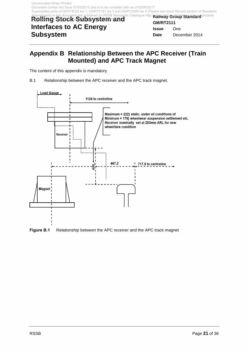
Appendix B Relationship Between the APC Receiver (Train Mounted) and APC Track Magnet
The content of this appendix is mandatory
B.1 Relationship between the APC receiver and the APC track magnet.
Figure B.1 Relationship between the APC receiver and the APC track magnet
Uncontrolled When Printed Document comes into force 07/03/2015 and is to be complied with as of 03/06/2017 Supersedes parts of GERT8025 Iss 1, GMRT2181 Iss 3 and GMRT2304 Iss 3 (Please see Issue Record section of Standard) Amendments to this document are published on RSSB Standards Catalogue http://www.rssb.co.uk/railway-group-standards Superseded by GMRT2111 Iss 2 with effect from 07/12/2019
Page 22 of 36 RSSB
Railway Group Standard
GM/RT2111
Issue One
Date December 2014
Rolling Stock Subsystem and Interfaces to AC Energy Subsystem
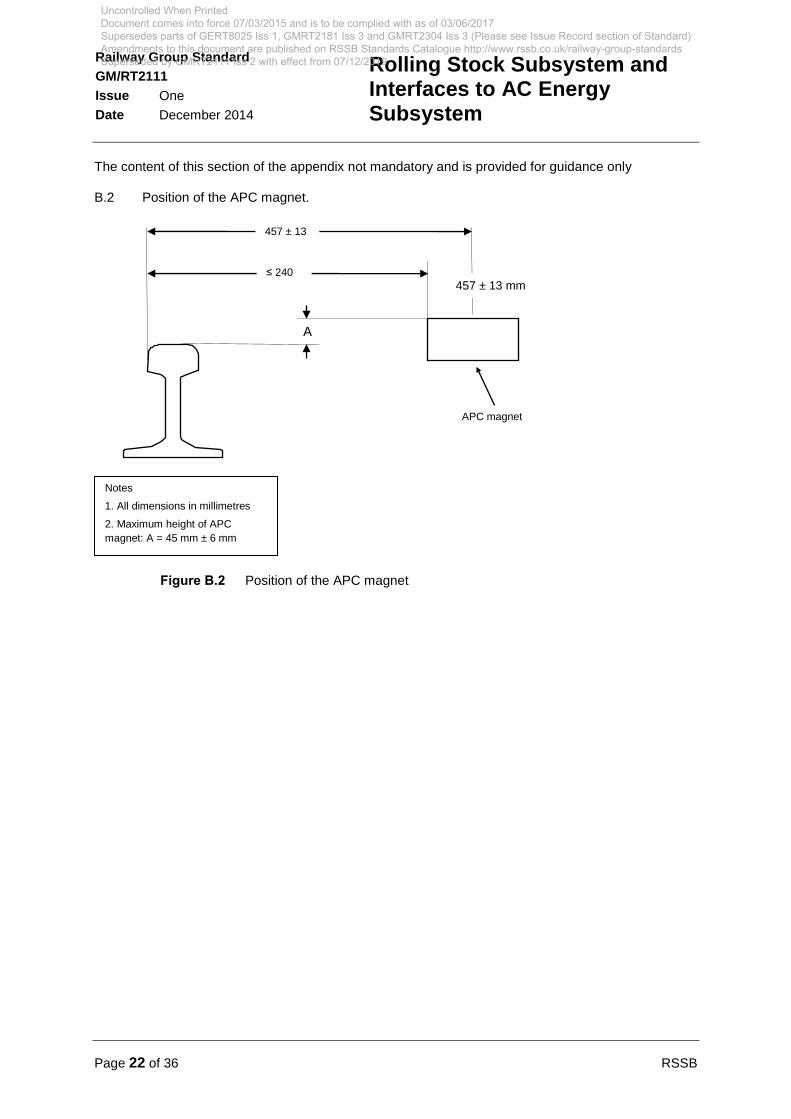
The content of this section of the appendix not mandatory and is provided for guidance only
B.2 Position of the APC magnet.
Figure B.2 Position of the APC magnet
A
APC magnet
457 ± 13
≤ 240
Notes
1. All dimensions in millimetres
2. Maximum height of APC
magnet: A = 45 mm ± 6 mm
457 ± 13 mm
Uncontrolled When Printed Document comes into force 07/03/2015 and is to be complied with as of 03/06/2017 Supersedes parts of GERT8025 Iss 1, GMRT2181 Iss 3 and GMRT2304 Iss 3 (Please see Issue Record section of Standard) Amendments to this document are published on RSSB Standards Catalogue http://www.rssb.co.uk/railway-group-standards Superseded by GMRT2111 Iss 2 with effect from 07/12/2019
RSSB Page 23 of 36
Railway Group Standard
GM/RT2111
Issue One
Date December 2014
Rolling Stock Subsystem and Interfaces to AC Energy Subsystem
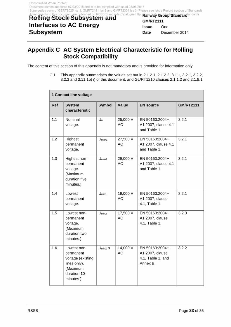
Appendix C AC System Electrical Characteristic for Rolling Stock Compatibility
The content of this section of this appendix is not mandatory and is provided for information only
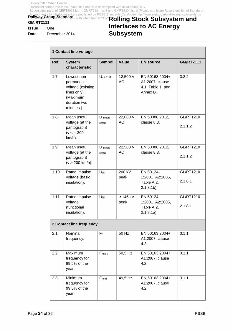
C.1 This appendix summarises the values set out in 2.1.2.1, 2.1.2.2, 3.1.1, 3.2.1, 3.2.2, 3.2.3 and 3.11.1b) i) of this document, and GL/RT1210 clauses 2.1.1.2 and 2.1.8.1.
1 Contact line voltage
Ref System
characteristic
Symbol Value EN source GM/RT2111
1.1 Nominal
voltage.
Un 25,000 V
AC
EN 50163:2004+
A1:2007, clause 4.1
and Table 1.
3.2.1
1.2 Highest
permanent
voltage.
Umax1 27,500 V
AC
EN 50163:2004+
A1:2007, clause 4.1
and Table 1.
3.2.1
1.3 Highest non-
permanent
voltage.
(Maximum
duration five
minutes.)
Umax2 29,000 V
AC
EN 50163:2004+
A1:2007, clause 4.1
and Table 1.
3.2.1
1.4 Lowest
permanent
voltage.
Umin1 19,000 V
AC
EN 50163:2004+
A1:2007, clause
4.1, Table 1.
3.2.1
1.5
Lowest non-
permanent
voltage.
(Maximum
duration two
minutes.)
Umin2 17,500 V
AC
EN 50163:2004+
A1:2007, clause
4.1, Table 1.
3.2.3
1.6 Lowest non-
permanent
voltage (existing
lines only).
(Maximum
duration 10
minutes.)
Umin2 a 14,000 V
AC
EN 50163:2004+
A1:2007, clause
4.1, Table 1, and
Annex B.
3.2.2
Uncontrolled When Printed Document comes into force 07/03/2015 and is to be complied with as of 03/06/2017 Supersedes parts of GERT8025 Iss 1, GMRT2181 Iss 3 and GMRT2304 Iss 3 (Please see Issue Record section of Standard) Amendments to this document are published on RSSB Standards Catalogue http://www.rssb.co.uk/railway-group-standards Superseded by GMRT2111 Iss 2 with effect from 07/12/2019
Page 24 of 36 RSSB
Railway Group Standard
GM/RT2111
Issue One
Date December 2014
Rolling Stock Subsystem and Interfaces to AC Energy Subsystem
1 Contact line voltage
Ref System
characteristic
Symbol Value EN source GM/RT2111
1.7 Lowest non-
permanent
voltage (existing
lines only).
(Maximum
duration two
minutes.)
Umin2 b 12,500 V
AC
EN 50163:2004+
A1:2007, clause
4.1, Table 1, and
Annex B.
3.2.2
1.8 Mean useful
voltage (at the
pantograph)
(v < = 200
km/h).
U mean
useful
22,000 V
AC
EN 50388:2012,
clause 8.3.
GL/RT1210
2.1.1.2
1.9 Mean useful
voltage (at the
pantograph)
(v > 200 km/h).
U mean
useful
22,500 V
AC
EN 50388:2012,
clause 8.3.
GL/RT1210
2.1.1.2
1.10 Rated impulse
voltage (basic
insulation).
UNi 200 kV
peak
EN 50124-
1:2001+A2:2005,
Table A.2,
2.1.8.1b).
GL/RT1210
2.1.8.1
1.11 Rated impulse
voltage
(functional
insulation).
UNi ≥ 145 kV
peak
EN 50124-
1:2001+A2:2005,
Table A.2,
2.1.8.1a).
GL/RT1210
2.1.8.1
2 Contact line frequency
2.1 Nominal
frequency.
Fn 50 Hz EN 50163:2004+
A1:2007, clause
4.2.
3.1.1
2.2 Maximum
frequency for
99.5% of the
year.
Fmax1 50,5 Hz EN 50163:2004+
A1:2007, clause
4.2.
3.1.1
2.3 Minimum
frequency for
99.5% of the
year.
Fmin1 49,5 Hz EN 50163:2004+
A1:2007, clause
4.2.
3.1.1
Uncontrolled When Printed Document comes into force 07/03/2015 and is to be complied with as of 03/06/2017 Supersedes parts of GERT8025 Iss 1, GMRT2181 Iss 3 and GMRT2304 Iss 3 (Please see Issue Record section of Standard) Amendments to this document are published on RSSB Standards Catalogue http://www.rssb.co.uk/railway-group-standards Superseded by GMRT2111 Iss 2 with effect from 07/12/2019

RSSB Page 25 of 36
Railway Group Standard
GM/RT2111
Issue One
Date December 2014
Rolling Stock Subsystem and Interfaces to AC Energy Subsystem
2 Contact line frequency
Ref System
characteristic
Symbol Value EN source GM/RT2111
2.4. Maximum
frequency for
100% of the
time.
Fmax2 52 Hz EN 50163:2004+
A1:2007, clause
4.2.
3.1.1
2.5 Minimum
frequency 100%
of the time.
Fmin2 47 Hz EN 50163:2004+
A1:2007, clause
4.2.
3.1.1
3 Contact line fault current
3.1 Maximum rms
fault current.
(Maximum
duration one
second.)
I sc rms 15 kA
(target)
EN 50388:2012,
clause 11.2 and
Table 7.
2.1.2.1
6 kA,
12 kA,
15 kA
(existing)
2.1.2.2
3.2
Maximum peak
fault current in
the first half
cycle.
I sc peak 2.5 times
maximum
rms fault
current
EN 60077-4:2003,
clause 5.3.6.1.
3.11.1b)
3.3
Maximum circuit
time constant at
the contact line.
τ Open
point
EN 62271-100:
2009+A1:2012,
clause 4.101.2.
3.11.1b) i)
Table C.1 Summary of parameters
Uncontrolled When Printed Document comes into force 07/03/2015 and is to be complied with as of 03/06/2017 Supersedes parts of GERT8025 Iss 1, GMRT2181 Iss 3 and GMRT2304 Iss 3 (Please see Issue Record section of Standard) Amendments to this document are published on RSSB Standards Catalogue http://www.rssb.co.uk/railway-group-standards Superseded by GMRT2111 Iss 2 with effect from 07/12/2019

Page 26 of 36 RSSB
Railway Group Standard
GM/RT2111
Issue One
Date December 2014
Rolling Stock Subsystem and Interfaces to AC Energy Subsystem
Appendix D Warning Line (previously known as Cant Rail Warning Line)
The content of this appendix is not mandatory and is provided for information only
D.1 Warning line
D.1.1 This appendix gives information on the warning line which provides a clear indication of the upper limit above which it is not safe to work on rail vehicles in overhead electrified areas without isolation of the OCL.
D.2 Application to rail vehicles
D.2.1 The warning line is applied to vehicles required to operate over 25 kV AC electrified lines, except steam locomotives.
D.3 Colour
D.3.1 The target colour should be light orange (BS 381C:1996 Reference No. 557).
D.3.2 Black or white for the warning line should be used in place of the light orange
colour where either:
a) The livery in the area where the warning line is to be applied is itself orange, such that a warning line as set out in D.3.1 would not be clearly visible.
Or
b) The livery contains areas of orange in close proximity to the area where the warning line is to be applied, such that the warning line, although clearly visible, may not be recognised as such.
D.3.3 Black or white is not substituted for light orange merely because it gives a sharper contrast with the livery. Orange is widely recognised as the colour of the warning line on rail vehicles and it should be used in all cases unless there is a problem of visibility of the warning line, or of recognising it as a warning line.
D.4 Height of the warning line above rail level
D.4.1 The warning line should be positioned taking into account the following
requirements:
a) The warning line is clearly visible when viewed from standing at rail level.
b) The top of the warning line mandated is no closer than 600 mm to the nearest train-mounted, exposed live electrical equipment, as set out in 3.16, and is measured as a ‘taut string’ distance. All parts of insulators are considered live for this purpose.
c) For vehicles that have a static height exceeding 3775 mm, the top of the warning line should not exceed an absolute maximum value of 3565 mm above rail level when the rail vehicle is in a tare condition with new wheels, and the suspension is in the in-service condition.
d) For vehicles that have a static height not exceeding 3775 mm, the top of the warning line should not exceed an absolute maximum value of 3390 mm above rail level when the rail vehicle is in a tare condition with new wheels, and the suspension is in the in-service condition.
Uncontrolled When Printed Document comes into force 07/03/2015 and is to be complied with as of 03/06/2017 Supersedes parts of GERT8025 Iss 1, GMRT2181 Iss 3 and GMRT2304 Iss 3 (Please see Issue Record section of Standard) Amendments to this document are published on RSSB Standards Catalogue http://www.rssb.co.uk/railway-group-standards Superseded by GMRT2111 Iss 2 with effect from 07/12/2019

RSSB Page 27 of 36
Railway Group Standard
GM/RT2111
Issue One
Date December 2014
Rolling Stock Subsystem and Interfaces to AC Energy Subsystem
e) Except as set out in f), the warning line should be placed within the range normally reached by carriage washing machines (not higher than 3300 mm above rail level) with the rail vehicle in tare condition with new wheels.
f) In circumstances where placing the line at or below 3300 mm prevents the warning line being carried over the top of areas which cannot be liveried, the height of the line, where it passes over such areas, should be kept to a value less than the absolute maximum value set out in c) or d), as appropriate.
D.4.2 Except under the conditions set out in D.4.4, the warning line should be
continuous and positioned so that it is not less than 3100 mm above rail level,
when the rail vehicle is in tare condition with new wheels and the suspension is in
the service condition.
D.4.3 Where practicable, the warning line should be placed above body side doors and
windows, rail vehicle end doors and windows, horns and destination and route
indicators.
D.4.4 Where there are glazed areas, ventilators, grilles, rubber elements or other parts
of the rail vehicle that cannot be liveried and which are of such a height that D.4.2
cannot be met, then one of either the following conditions should be applied:
a) Carry the warning line below 3100 mm in cases where it can be positioned sufficiently high for it to be readily recognisable as a warning line.
Or
b) The warning line should be terminated immediately either side of the obstruction. Whenever the warning line is terminated to avoid an obstruction a ‘Danger: electricity’ warning sign, as defined in The Health and Safety (Safety Signs and Signals) Regulations 1996 - Statutory Instruments, 1996 No. 341 (Schedule 1), with the supplementary text ‘Overhead Live Wires’, should be fitted within 200 mm of each termination of the warning line, where practicable, on the rail vehicle end and at the same level as the warning line.
Uncontrolled When Printed Document comes into force 07/03/2015 and is to be complied with as of 03/06/2017 Supersedes parts of GERT8025 Iss 1, GMRT2181 Iss 3 and GMRT2304 Iss 3 (Please see Issue Record section of Standard) Amendments to this document are published on RSSB Standards Catalogue http://www.rssb.co.uk/railway-group-standards Superseded by GMRT2111 Iss 2 with effect from 07/12/2019
Page 28 of 36 RSSB
Railway Group Standard
GM/RT2111
Issue One
Date December 2014
Rolling Stock Subsystem and Interfaces to AC Energy Subsystem
Appendix E Bonding of Rail Vehicles’ 25 kV Equipment
The content of this appendix is not mandatory and is provided for information only
E.1 This appendix provides information on the methods that have been used for the earthing and bonding of rail vehicles to the running rail potential.
E.2 To facilitate safe working on the high voltage electrical equipment on rail vehicles which can be supplied from an OCL, system protection is provided traditionally by an isolating cock and mechanically interlocked earthing switch. This system is provided mainly to protect depot staff when working on the roof equipment of trains.
E.3 A manual isolating cock (isolating device) is provided to remove the air supply from the pantograph up valve and to prevent the pantograph from being raised. When the device is operated, this isolates the air supply from the pantograph up valve and so makes it impossible to raise the pantograph when it is isolated.
E.4 An earthing (safety bonding) switch is provided to bond all high voltage equipment and when it is placed in the closed (earthed) position, it bonds both:
a) The pantograph, roof connections and any other equipment on the supply side of the train in-feed circuit breaker to the rail vehicle main body structure.
And
b) The roof input bushing, high voltage cable and any other primary circuit equipment on the load side of the train in-feed circuit breaker, to the rail vehicle main body structure.
E.5 The earthing (safety bonding) switch has two moving elements, each one making contact with a matching fixed element on the train in-feed circuit breaker, on each side of its open contact.
E.6 The earthing (safety bonding) switch operating handle and the pantograph isolating cock handle are interlocked to provide all of the following:
a) When the isolating cock is in the open position, that is to say, normal service, the safety bonding switch is locked open.
b) When the safety bonding switch is in the bonded position, the isolating cock is locked in the isolated position.
c) With air applied to the pantograph, the safety bonding switch is locked in the open position and remains so until the air pressure in the pantograph air motor is reduced to a value well below that at which the pantograph leaves the wire.
E.7 Where rail vehicles are fitted with more than one pantograph and the pantographs are permanently electrically connected together, their isolation and earthing (safety bonding) is provided as if they were a single pantograph.
E.8 Where rail vehicles are fitted with more than one pantograph and the pantographs are not permanently electrically connected together, their isolation and earthing (safety bonding) is provided individually for each pantograph location.
Uncontrolled When Printed Document comes into force 07/03/2015 and is to be complied with as of 03/06/2017 Supersedes parts of GERT8025 Iss 1, GMRT2181 Iss 3 and GMRT2304 Iss 3 (Please see Issue Record section of Standard) Amendments to this document are published on RSSB Standards Catalogue http://www.rssb.co.uk/railway-group-standards Superseded by GMRT2111 Iss 2 with effect from 07/12/2019
RSSB Page 29 of 36
Railway Group Standard
GM/RT2111
Issue One
Date December 2014
Rolling Stock Subsystem and Interfaces to AC Energy Subsystem
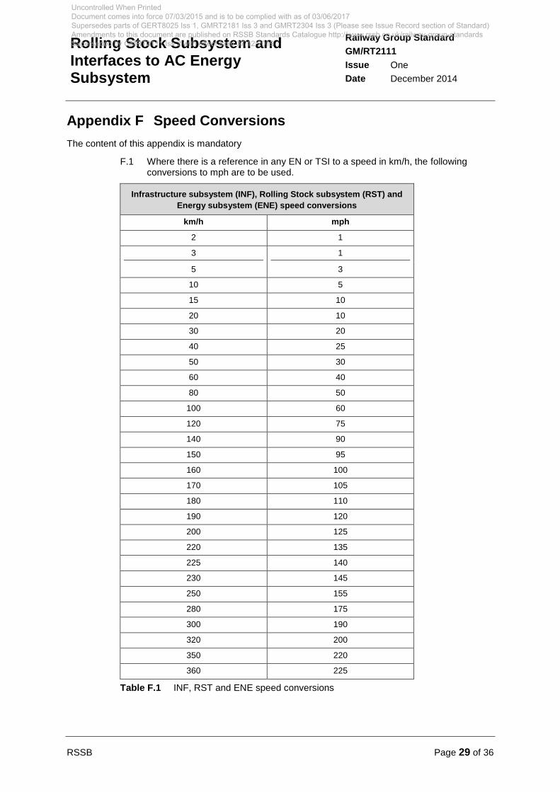
Appendix F Speed Conversions
The content of this appendix is mandatory
F.1 Where there is a reference in any EN or TSI to a speed in km/h, the following conversions to mph are to be used.
Infrastructure subsystem (INF), Rolling Stock subsystem (RST) and
Energy subsystem (ENE) speed conversions
km/h mph
2 1
3 1
5 3
10 5
15 10
20 10
30 20
40 25
50 30
60 40
80 50
100 60
120 75
140 90
150 95
160 100
170 105
180 110
190 120
200 125
220 135
225 140
230 145
250 155
280 175
300 190
320 200
350 220
360 225
Table F.1 INF, RST and ENE speed conversions
Uncontrolled When Printed Document comes into force 07/03/2015 and is to be complied with as of 03/06/2017 Supersedes parts of GERT8025 Iss 1, GMRT2181 Iss 3 and GMRT2304 Iss 3 (Please see Issue Record section of Standard) Amendments to this document are published on RSSB Standards Catalogue http://www.rssb.co.uk/railway-group-standards Superseded by GMRT2111 Iss 2 with effect from 07/12/2019

Page 30 of 36 RSSB
Railway Group Standard
GM/RT2111
Issue One
Date December 2014
Rolling Stock Subsystem and Interfaces to AC Energy Subsystem
Definitions
AC Energy Subsystem
The Energy TSI states that the AC Energy Subsystem consists of:
Substations: connected on the primary side to the high-voltage grid, with transformation of the high-voltage to a voltage and / or conversion to a power supply system suitable for the trains. On the secondary side, substations are connected to the railway contact line system.
Sectioning locations: electrical equipment located at intermediate locations between substations to supply and parallel contact lines, and to provide protection, isolation and auxiliary supplies.
Separation sections: equipment required to provide the transition between electrically different systems or between different phases of the same electrical system.
Contact line system: a system that distributes the electrical energy to the trains running on the route and transmits it to the trains by means of current collectors. The contact line system is also equipped with manually or remotely controlled disconnectors which are required to isolate sections or groups of the contact line system according to operational necessity. Feeder lines are also part of the contact line system.
Return circuit: all conductors which form the intended path for the traction return current and which are additionally used under fault conditions. Therefore, so far as this aspect is concerned, the return circuit is part of the energy subsystem and has an interface with the infrastructure subsystem.
Basic insulation
Insulation of hazardous-live-parts, which provides basic protection. Note: This concept does not apply to insulation used exclusively for functional purposes. [IEV ref 195-06-06]
Contact force
Vertical force applied by the pantograph to the overhead contact line (OCL). [EN 50367:2012 and EN 50317:2012]
Contact line system
A system that distributes the electrical energy to the trains running on the route and transmits it to the trains by means of current collectors.
Contact wire uplift
Vertical upward movement of the contact wire due to the force produced from the pantograph. [EN 50119:2009+A1:2013]
Current collector
Equipment fitted to the rail vehicle and intended to collect current from a contact wire or conductor rail. [IEV ref 811-32-01]
Electric shock
A dangerous physiological effect resulting from the passing of an electric current through the human body or livestock. [IEV ref 195-01-04]
European Register of Authorised Types of Vehicles (Vehicle register)
National register maintained by each Member State of the rail vehicles authorised in its territory.
Uncontrolled When Printed Document comes into force 07/03/2015 and is to be complied with as of 03/06/2017 Supersedes parts of GERT8025 Iss 1, GMRT2181 Iss 3 and GMRT2304 Iss 3 (Please see Issue Record section of Standard) Amendments to this document are published on RSSB Standards Catalogue http://www.rssb.co.uk/railway-group-standards Superseded by GMRT2111 Iss 2 with effect from 07/12/2019

RSSB Page 31 of 36
Railway Group Standard
GM/RT2111
Issue One
Date December 2014
Rolling Stock Subsystem and Interfaces to AC Energy Subsystem
Functional insulation
Insulation between conductive parts, necessary for the proper functioning of the equipment. [IEV ref 195-02-41]
Failure
The termination of the ability of an item to perform a required function. [IEV ref 191-04-01]
Fixed formation units –
25 kV or dual voltage fixed formation unit. A fixed formation unit is only operated with a single pantograph raised at any one time:
AC fixed formation units – 25 kV-only fixed formation unit.
AC / DC fixed formation units – dual voltage fixed formation unit.
Gauge
Set of rules including a reference contour and its associated calculation rules allowing defining the outer dimensions of the rail vehicle and the space to be cleared by the infrastructure.
Note: According to the calculation method implemented, the gauge is a static, kinematic or dynamic.
Lateral deviation
Deviation of the contact wire from the track centre line under action of a crosswind. [EN 50367:2012]
Line speed
Maximum speed measured in km/h for which a line has been designed.
Live part
Any conductor and any conductive part of electrical equipment intended to be energised in normal use. [IEV ref 195-02-19-modified]. Insulators are considered to be live parts.
Maximum contact wire height
Maximum possible contact wire height which the pantograph is required to reach, in all conditions. [EN 50119:2009+A1:2013]
Mean contact force
Statistical mean value of the contact force. [EN 50367:2012]
Mean useful voltage train
Voltage identifying the dimensioning train and enables the effect on its performance to be quantified. [EN 50388:2012]
Mean useful voltage zone
Voltage giving an indication of the quality of the power supply in a geographic zone during the peak traffic period in the timetable. [EN 50388:2012]
Minimum contact wire height
A minimum value of the contact wire height in the span, in order to avoid the arcing between one or more contact wires and rail vehicles in all conditions. [EN 50119:2009+ A1:2013]
Uncontrolled When Printed Document comes into force 07/03/2015 and is to be complied with as of 03/06/2017 Supersedes parts of GERT8025 Iss 1, GMRT2181 Iss 3 and GMRT2304 Iss 3 (Please see Issue Record section of Standard) Amendments to this document are published on RSSB Standards Catalogue http://www.rssb.co.uk/railway-group-standards Superseded by GMRT2111 Iss 2 with effect from 07/12/2019
Page 32 of 36 RSSB
Railway Group Standard
GM/RT2111
Issue One
Date December 2014
Rolling Stock Subsystem and Interfaces to AC Energy Subsystem
Nominal contact wire height
A nominal value of the contact wire height at a support in the normal conditions. [EN 50119:2009+A1:2013]
Nominal voltage
Voltage by which an installation or part of an installation is designated. [EN 50163:2004+ A1:2007]
Normal service
Planned timetable service.
On-track machine
A rail-mounted machine that meets the requirements of GM/RT2400.
Open points
Requirements formally identified in a TSI or Railway Group Standard for which no common requirement has been agreed.
Overhead contact line (OCL)
Contact line placed above (or beside) the upper limit of the rail vehicle gauge and supplying vehicles with electric energy through roof-mounted current collection equipment. [IEV ref 811-33-02]
Pantograph exclusion zone
The length of track relative to a defined OCL feature (for example, an overlap) within which the pantograph of an electric train does not touch the contact wire when the train is stationary or moving at a slow speed, in order to prevent electrical arcing.
Passing electrical clearance
The distance, being created by a momentary reduction of the static electrical clearance, caused by the dynamic interaction of the pantograph and the OCL during the passage of electric trains.
Rail vehicle
Any vehicle, moving either under its own power (locomotives fixed formation units and multiple units) or hauled by another vehicle (coaches, railcar trailers, vans and wagons), on-track machine, road-rail vehicle or rail-mounted maintenance machine.
Rated impulse voltage (UNi)
Impulse voltage value assigned to the system or part of it, characterising the specified withstand capability of its insulation against transient overvoltages. [EN50124-1:2001+A2:2005, 1.3.2.7 – modified]
Register of Infrastructure (RINF)
A register that shall be maintained for each TSI-certified line that describes the main features and measures of each subsystem and their correlation with the relevant TSI.
Return circuit
All conductors which form the intended path for the traction return current and the current under fault conditions. [EN 50122-1:2011+A1:2011]
Static contact force
Mean vertical force exerted upwards by the pantograph head on the OCL, and caused by the pantograph-raising device, while the pantograph is raised and the rail vehicle is at a standstill. [EN 50367:2012]
Uncontrolled When Printed Document comes into force 07/03/2015 and is to be complied with as of 03/06/2017 Supersedes parts of GERT8025 Iss 1, GMRT2181 Iss 3 and GMRT2304 Iss 3 (Please see Issue Record section of Standard) Amendments to this document are published on RSSB Standards Catalogue http://www.rssb.co.uk/railway-group-standards Superseded by GMRT2111 Iss 2 with effect from 07/12/2019

RSSB Page 33 of 36
Railway Group Standard
GM/RT2111
Issue One
Date December 2014
Rolling Stock Subsystem and Interfaces to AC Energy Subsystem
Static electrical clearance
The distance forming insulation in air between:
a) Exposed live parts of the OCL system and the parts of rail vehicles that are earthed via the fixed installation.
b) Exposed live parts of the OCL system and earthed parts of the OCL system.
c) Exposed live parts of the OCL system and fixed assets.
d) Exposed live parts of electric rail vehicles and earthed parts of the OCL system.
e) Exposed live parts of electric rail vehicles and fixed assets.
Subsystem
One of the subsystems (of the European railway system) identified by the Interoperability Directive. Subsystems can be structural or functional.
Switching frequency related harmonics
These are the frequencies that appear as a group of frequencies and are related to the switching frequency of the line converter.
Train
An operational train which may consist of locomotives, wagons, coaches, multiple units or a single fixed formation unit.
Uncontrolled When Printed Document comes into force 07/03/2015 and is to be complied with as of 03/06/2017 Supersedes parts of GERT8025 Iss 1, GMRT2181 Iss 3 and GMRT2304 Iss 3 (Please see Issue Record section of Standard) Amendments to this document are published on RSSB Standards Catalogue http://www.rssb.co.uk/railway-group-standards Superseded by GMRT2111 Iss 2 with effect from 07/12/2019
Page 34 of 36 RSSB
Railway Group Standard
GM/RT2111
Issue One
Date December 2014
Rolling Stock Subsystem and Interfaces to AC Energy Subsystem
Abbreviations
AC
Alternating current.
ADD
Automatic dropping device.
APC
Automatic power control.
ARL
Above rail level.
DC
Direct current.
ENE
Energy subsystem.
IEV
International Electrotechnical Vocabulary IEC 60050 series available on line as ‘Electropedia’.
IM
Infrastructure manager.
INF
Infrastructure subsystem.
LOC&PAS
Locomotives & Passenger Carriages TSI. Part of the RST.
OCL
Overhead contact line.
RINF
Register of Infrastructure.
rms
Root mean squared.
RST
Rolling stock subsystem.
TSI
Technical Specifications for Interoperability.
Uncontrolled When Printed Document comes into force 07/03/2015 and is to be complied with as of 03/06/2017 Supersedes parts of GERT8025 Iss 1, GMRT2181 Iss 3 and GMRT2304 Iss 3 (Please see Issue Record section of Standard) Amendments to this document are published on RSSB Standards Catalogue http://www.rssb.co.uk/railway-group-standards Superseded by GMRT2111 Iss 2 with effect from 07/12/2019

RSSB Page 35 of 36
Railway Group Standard
GM/RT2111
Issue One
Date December 2014
Rolling Stock Subsystem and Interfaces to AC Energy Subsystem
References
The Catalogue of Railway Group Standards gives the current issue number and status of documents published by RSSB. This information is also available from www.rgsonline.co.uk.
RGSC 01 Railway Group Standards Code
RGSC 02 Standards Manual
Documents referenced in the text
Railway Group Standards
GL/RT1210 AC Energy Subsystem and Interfaces to Rolling Stock Subsystem
GM/RT2400 Engineering Design of On-Track Machines in Running Mode
RSSB documents
GL/GN1610 Guidance on AC Energy Subsystem and Interfaces to Rolling Stock Subsystem
GM/GN2611 Guidance on Rolling Stock Subsystem and Interfaces to AC Energy Subsystem
GM/GN2613 Guidance on Rolling Stock Subsystem and Interfaces to DC Energy Subsystem
Other references
BS 381C:1996 Specification for colours for identification, coding and special purposes
EN 50119:2009+A1:2013 Railway applications. Fixed installations. Electric traction overhead contact lines
EN 50122-1:2011+A1:2011 Railway applications. Fixed installations. Electrical safety, earthing and the return circuit. Part 1: Protective provisions against electric shock
EN 50124-1:2001+A2:2005 Railway applications. Insulation coordination. Part 1: Basic requirements. Clearances and creepage distances for all electrical and electronic equipment
EN 50153:2002 Railway applications. Rolling stock. Protective provisions relating to electrical hazards
EN 50163:2004+A1:2007 Railway applications. Supply voltages of traction systems
EN 50206-1:2010 Railway applications. Rolling stock. Pantographs: Characteristics and tests. Part 1: Pantographs for main line vehicles
EN 50317:2012 Railway applications. Current collection systems. Requirements for and validation of measurements of the dynamic interaction between pantograph and overhead contact line
EN 50367:2012 Railway applications. Current collection systems. Technical criteria for the interaction between pantograph and overhead line (to achieve free access)
Uncontrolled When Printed Document comes into force 07/03/2015 and is to be complied with as of 03/06/2017 Supersedes parts of GERT8025 Iss 1, GMRT2181 Iss 3 and GMRT2304 Iss 3 (Please see Issue Record section of Standard) Amendments to this document are published on RSSB Standards Catalogue http://www.rssb.co.uk/railway-group-standards Superseded by GMRT2111 Iss 2 with effect from 07/12/2019
Page 36 of 36 RSSB
Railway Group Standard
GM/RT2111
Issue One
Date December 2014
Rolling Stock Subsystem and Interfaces to AC Energy Subsystem
EN 50388:2012 Railway applications. Power supply and rolling stock. Technical criteria for the coordination between power supply (substation) and rolling stock to achieve interoperability
EN 60077-4:2003 Railway applications. Electric equipment for rolling stock. Part 4: Electrotechnical components. Rules for AC circuit-breakers
EN 62271-100:2009+A1:2012 High-voltage switchgear and controlgear. Alternating current circuit-breakers
IEV 60050 series International Electrotechnical Vocabulary (IEV) available on line as ‘Electropedia’
Details of the current TSIs and links to the documents are available at: http://www.rssb.co.uk/SiteCollectionDocuments/rgs/TSI_status_summary.pdf
The Health and Safety (Safety Signs and Signals) Regulations 1996 − Statutory Instruments, 1996 No. 341
Other relevant documents
Railway Group Standards
GE/RT8015 Electromagnetic Compatibility between Railway Infrastructure and Trains
GE/RT8270 Assessment of Compatibility of Rolling Stock and Infrastructure
GK/RT0045 Lineside Signals, Indicators and Layout of Signals
GK/RT0058 Lineside Signal Aspect and Indication Requirements
GM/RT2113 Rolling Stock Subsystem and Interfaces to DC Energy Subsystem [to be published]
GO/RT3215 Requirements for the Weekly Operating Notice, Periodical Operating Notice and Sectional Appendix
Other references
BR 12034/17 Railway Electrification 25 kV AC Design Acceptance Measures
BS 2754 (IEC 536) Construction of Electrical Equipment for Protection Against Electric Shock [withdrawn]
BS 7671:2008+A1:2011 Requirements for electrical installations. IET Wiring Regulations
EN 50122-2:2010 Railway applications. Fixed installations. Electrical safety, earthing and the return circuit. Part 2: Provisions against the effects of stray currents caused by DC traction systems
EN 50318:2002 Railway applications. Current collection systems. Validation of simulation of the dynamic interaction between pantograph and overhead contact line
European Railway Agency ‘Guide for the application of CR ENE TSI (According to Framework Mandate C (2007)3371 final of 13/07/2007)’
Uncontrolled When Printed Document comes into force 07/03/2015 and is to be complied with as of 03/06/2017 Supersedes parts of GERT8025 Iss 1, GMRT2181 Iss 3 and GMRT2304 Iss 3 (Please see Issue Record section of Standard) Amendments to this document are published on RSSB Standards Catalogue http://www.rssb.co.uk/railway-group-standards Superseded by GMRT2111 Iss 2 with effect from 07/12/2019