roof load assessment - allcott commercial
TRANSCRIPT

Roof Load Assessment Relating to: Proposed PV Panel Installation At: XXXX
XXXX
Report date: XXXXXX

XXXX Allcott Associates LLP
JOB REF: XXXX SF18/v1/28/05/2014
CLIENT: XXXX
ii
Project preface
Client(s) name:
XXXX
Client(s) address: XXXX XXXX
Prepared at: Allcott Associates LLP
Unit 3, The Fosse Fosse Way Radford Semele Leamington Spa CV31 1XN
Document prepared by:
James Bodicoat MEng, CEng, MICE, MIStructE
Job reference:
XXXX
Reviewed by:
Matthew Baker

XXXX Allcott Associates LLP
JOB REF: XXXX SF18/v1/28/05/2014
CLIENT: XXXX
iii

XXXX Allcott Associates LLP
JOB REF: XXXX SF18/v1/28/05/2014
CLIENT: XXXX
1
Client Proposal for PV Array

XXXX Allcott Associates LLP
JOB REF: XXXX SF18/v1/28/05/2014
CLIENT: XXXX
2
Table of contents
Project preface ii
1 Introduction 3
1.1 Instructions 3
1.2 Brief 3
1.3 Basis of Information 4
2 Description of Existing Structure 5
2.1 Block A Roof – Area 1 6
2.2 Block A Roof – Area 2 6
2.3 Block B Roof 7
3 Loading 9
3.1 Dead Loads 9
3.2 Imposed Loads 9
4 Summary of Roof Analyses 13
4.1 Block A Area 1 13
4.2 Block A Area 2 13
4.3 Block B 13
4.4 Other Considerations 14
5 Conclusion 15
6 Rights of Originator 16
7 Conditions 17
Appendix A – Loading Calculations Appendix B – Block A Area 1 Calculations Appendix C – Block A Area 2 Calculations Appendix D – Block D Calculation
Appendices

XXXX Allcott Associates LLP
JOB REF: XXXX SF18/v1/28/05/2014
CLIENT: XXXX
3
1 Introduction
1.1 Instructions
In accordance with instructions received from XXXX we have carried out an assessment of
the ‘spare’ load capacity on the roofs of the XXXX commercial premises at XXXXX.
The report provides a background to the nature of the existing structure and existing roof
loading information, followed by a structural review of the different roof sections.
The load assessments consider the spare load capacity of the roof, i.e. the capacity available,
and compare this with the anticipated additional load due to the proposed PV installation.
1.2 Brief
We understand from XXXX that an array of 135 photovoltaic panels is proposed in the
arrangement shown in the figure below.
The specification for the proposed panels is a follows:

XXXX Allcott Associates LLP
JOB REF: XXXX SF18/v1/28/05/2014
CLIENT: XXXX
4
• Panel dimensions: 1.0m wide by 1.69m long
• Panel weight: 22.5kg per panel
• Total weight of installation: 3,040kg
• Uniformly Distributed Load: 0.13 kN/m2
• Fixing method: Positive screw fixings to roof sheeting, no kentledge
1.3 Basis of Information
The review is based on the following information:
• Limited archive drawings provided by XXXX for the original construction;
• Visual inspection of the roof structure above the ceiling tiles, undertaken on 24th
September 2020.
All comments are based on visual inspection only and no removal of fixed finishes was
carried out. Similarly, the roof voids were not entered as there were no permanent load
bearing walkways or platforms within the roof. Therefore all measurements taken are to be
considered approximate.
No below ground investigations have been carried out and no drainage survey has been
undertaken.
Where the terms “right hand” or “left hand” are used, they assume that the reader is facing
the front of the property with the main access door situated within the front elevation.

XXXX Allcott Associates LLP
JOB REF: XXXX SF18/v1/28/05/2014
CLIENT: XXXX
5
2 Description of Existing Structure
The existing building comprises two adjoined single storey structures. For the purposes of
this assessment, they are referred to as Block A and Block B, as noted on the key plan below.
Approximate plan dimensions of each block are as follows:
• Block A – 7.1m wide by 29m long
• Block B – 12.2m wide by 19.4m long
In both cases, they comprise a duo pitch roof clad with a trapezoidal-profile metal cladding,
understood to be Jackson Roofing J/1000. The roof cladding is supported on steel or timber
purlins, spanning between steel or timber roof trusses of varying form, depending on
location. The roof trusses are supported on either steel or brickwork columns.
Walls are typically brickwork, with some areas clad in the same profiled metal cladding as
used on the roof.

XXXX Allcott Associates LLP
JOB REF: XXXX SF18/v1/28/05/2014
CLIENT: XXXX
6
2.1 Block A Roof – Area 1
The roof to Area 1 of Block A (towards the front of the building) comprises steel trusses at
approximately 3.85m centres. From measurements taken on site, the height of the apex is
approximately 3.1m above the eaves level, giving a pitch of approximately 40.9°.
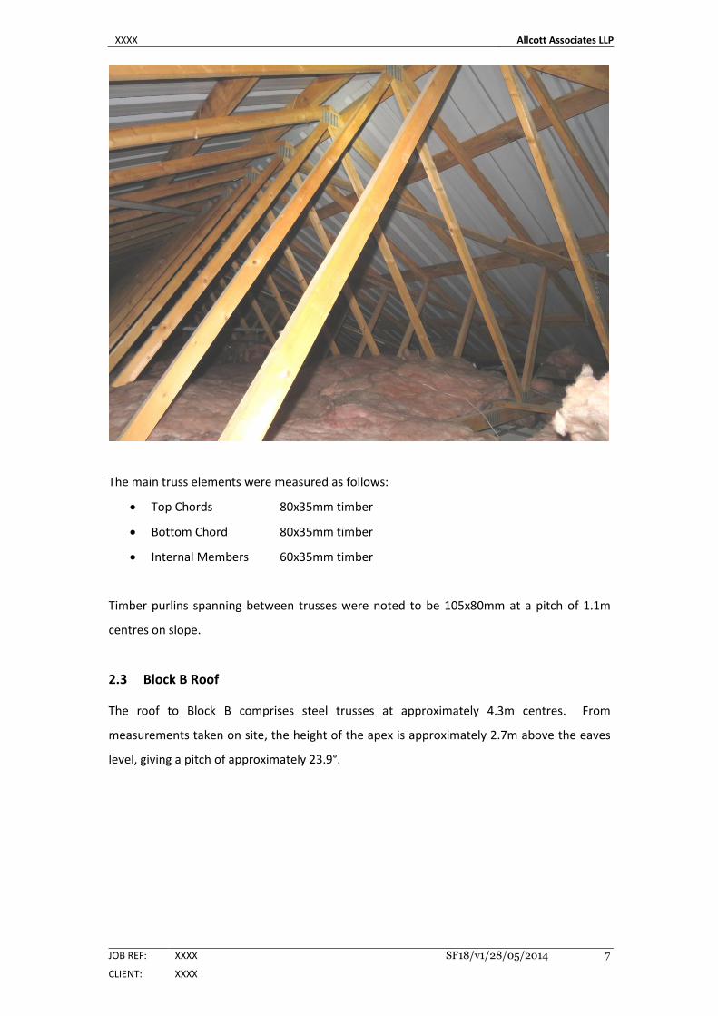
The main truss elements were measured as follows:
• Top Chords 90x65x7mm unequal angle
• Bottom Chord 65x50x5mm unequal angle
• Internal Members 50x50x6mm equal angles
Purlins spanning between trusses were noted to be 75x50x5mm unequal angles at a pitch of
1.1m centres on slope.
2.2 Block A Roof – Area 2
The roof to Area 2 of Block A (towards the rear of the building) comprises domestic style
engineered timber roof joists at 600mm centres. It appears that these replaced former
timber trusses at a larger spacing, possible when the roof was re-clad. The width and the
height of the trusses is similar to Area 1, such that the is no change to the line of the roof
cladding externally between Areas 1 and 2.
XXXX Allcott Associates LLP
JOB REF: XXXX SF18/v1/28/05/2014
CLIENT: XXXX
7
The main truss elements were measured as follows:
• Top Chords 80x35mm timber
• Bottom Chord 80x35mm timber
• Internal Members 60x35mm timber
Timber purlins spanning between trusses were noted to be 105x80mm at a pitch of 1.1m
centres on slope.
2.3 Block B Roof
The roof to Block B comprises steel trusses at approximately 4.3m centres. From
measurements taken on site, the height of the apex is approximately 2.7m above the eaves
level, giving a pitch of approximately 23.9°.

XXXX Allcott Associates LLP
JOB REF: XXXX SF18/v1/28/05/2014
CLIENT: XXXX
8
The main truss elements were measured as follows:
• Top Chords 75x75x6mm equal angle
• Bottom Chord 60x60x5mm equal angle
• Internal Members 50x50x5mm equal angles
Purlins spanning between trusses were noted to be 75x75x5mm unequal angles at a
maximum pitch of 1.4m centres on slope.
XXXX Allcott Associates LLP
JOB REF: XXXX SF18/v1/28/05/2014
CLIENT: XXXX
9
3 Loading
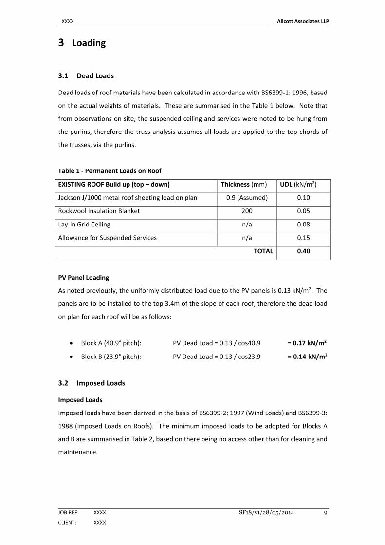
3.1 Dead Loads
Dead loads of roof materials have been calculated in accordance with BS6399-1: 1996, based
on the actual weights of materials. These are summarised in the Table 1 below. Note that
from observations on site, the suspended ceiling and services were noted to be hung from
the purlins, therefore the truss analysis assumes all loads are applied to the top chords of
the trusses, via the purlins.
Table 1 - Permanent Loads on Roof
EXISTING ROOF Build up (top – down) Thickness (mm) UDL (kN/m2)
Jackson J/1000 metal roof sheeting load on plan 0.9 (Assumed) 0.10
Rockwool Insulation Blanket 200 0.05
Lay-in Grid Ceiling n/a 0.08
Allowance for Suspended Services n/a 0.15
TOTAL 0.40
PV Panel Loading
As noted previously, the uniformly distributed load due to the PV panels is 0.13 kN/m2. The
panels are to be installed to the top 3.4m of the slope of each roof, therefore the dead load
on plan for each roof will be as follows:
• Block A (40.9° pitch): PV Dead Load = 0.13 / cos40.9 = 0.17 kN/m2
• Block B (23.9° pitch): PV Dead Load = 0.13 / cos23.9 = 0.14 kN/m2
3.2 Imposed Loads
Imposed Loads
Imposed loads have been derived in the basis of BS6399-2: 1997 (Wind Loads) and BS6399-3:
1988 (Imposed Loads on Roofs). The minimum imposed loads to be adopted for Blocks A
and B are summarised in Table 2, based on there being no access other than for cleaning and
maintenance.

XXXX Allcott Associates LLP
JOB REF: XXXX SF18/v1/28/05/2014
CLIENT: XXXX
10
Table 2 - Minimum Imposed Load on Roof (clause 4.3.1)
Description UDL (kN/m2) Point Load
(kN)
Block A (roof pitch > 30°) 0.38 0.9
Block B (roof pitch < 30°) 0.60 0.9
Snow Loading
Snow Load calculations are provided in Appendix A. The uniform snow load on the roofs has
been calculated from Block B (worst case) as 0.56 kN/m2, and an asymmetric snow load
acting on one side of the roof of 0.73 kN/m2.
In addition, drifted snow loading has been considered to the valley created between Blocks
A and B. This has been calculated as varying form zero at the apex of each block to a
maximum of 2.26 kN/m2 at the valley between the two blocks.
The uniform snow load is less than the minimum imposed load on the roof, and will not
coincide with the minimum imposed load for cleaning and maintenance, as roof access will
restricted during times of heavy snowfall. Similarly, the asymmetric snow load is less than
the drifted snow load, therefore this shall be disregarded in the truss analysis.
Wind Loading
Wind load calculations are provided in Appendix A for each block.
For Block A, the maximum downward net pressure was calculated under roof wind load case
2 as 0.47kN/m2 for a limited Zone A region adjacent to the eaves. Under the same load case,
the downward net wind pressure for the larger Zone C was calculated as 0.4kN/m2. For all
other wind load cases, the net pressures were calculated to be uplift (suction).
For Block B, the maximum downward net pressure was calculated under roof wind load case
2 as 0.36kN/m2 for a limited Zone A region adjacent to the eaves. Under the same load case,
the downward net wind pressure for the larger Zone C was calculated as 0.27kN/m2. For all
other wind load cases, the net pressures were calculated to be uplift (suction).

XXXX Allcott Associates LLP
JOB REF: XXXX SF18/v1/28/05/2014
CLIENT: XXXX
11
When considering load combinations including the additional weight of the PV Panels, wind
suction will be beneficial therefore will not be considered further as it will not result in the
critical load combination. Similarly, give the maximum downward net wind pressure was
calculated as less than the minimum access load, the imposed load of 0.6kN/m2 will be more
onerous, therefore wind loading will not result in the worst case load combination.
Notional Horizontal loads
Notional horizontal loading on the existing structure will not become any more onerous than
the existing condition as a result of the installation of PV-panels; therefore no specific checks
are to be carried out in this respect.
Load combinations
The truss analyses will consider the following load combinations:
For Strength:
• 1.4 Dead + 1.4 PV Panels +1.6 Imposed Load
• 1.4 Dead + 1.4 PV Panels +1.6 Drifted Snow Load
For Serviceability:
• 1.0 Dead + 1.0 PV Panels +1.0 Imposed Load
• 1.0 Dead + 1.0 PV Panels +1.0 Drifted Snow Load

XXXX Allcott Associates LLP
JOB REF: XXXX SF18/v1/28/05/2014
CLIENT: XXXX
12
XXXX Allcott Associates LLP
JOB REF: XXXX SF18/v1/28/05/2014
CLIENT: XXXX
13
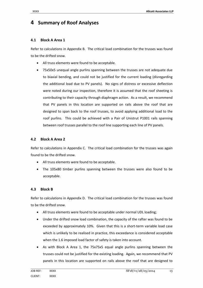
4 Summary of Roof Analyses
4.1 Block A Area 1
Refer to calculations in Appendix B. The critical load combination for the trusses was found
to be the drifted snow.
• All truss elements were found to be acceptable.
• 75x50x5 unequal angle purlins spanning between the trusses are not adequate due
to biaxial bending, and could not be justified for the current loading (disregarding
the additional load due to PV panels). No signs of distress or excessive deflection
were noted during our inspection, therefore it is assumed that the roof sheeting is
contributing to their capacity through diaphragm action. As a result, we recommend
that PV panels in this location are supported on rails above the roof that are
designed to span back to the roof trusses, to avoid applying additional load to the
roof purlins. This could be achieved with a Pair of Unistrut P1001 rails spanning
between roof trusses parallel to the roof line supporting each line of PV panels.
4.2 Block A Area 2
Refer to calculations in Appendix C. The critical load combination for the trusses was again
found to be the drifted snow.
• All truss elements were found to be acceptable.
• The 105x80 timber purlins spanning between the trusses were also found to be
acceptable.
4.3 Block B
Refer to calculations in Appendix D. The critical load combination for the trusses was found
to be the drifted snow.
• All truss elements were found to be acceptable under normal UDL loading;
• Under the drifted snow load combination, the capacity of the rafter was found to be
exceeded by approximately 10%. Given that this is a short-term variable load case
which is unlikely to be realised in practice, this exceedance is considered acceptable
when the 1.6 imposed load factor of safety is taken into account.
• As with Block A Area 1, the 75x75x5 equal angle purlins spanning between the
trusses could not be justified for the existing loading. Again, we recommend that PV
panels in this location are supported on rails above the roof that are designed to

XXXX Allcott Associates LLP
JOB REF: XXXX SF18/v1/28/05/2014
CLIENT: XXXX
14
span back to the roof trusses, to avoid applying additional load to the roof purlins.
This could be achieved with a Pair of Unistrut P1001 rails spanning between roof
trusses parallel to the roof line supporting each line of PV panels.
4.4 Other Considerations
Wind uplift was disregarded in the assessment of the existing roof trusses, as it was a
beneficial action, but it should be taken into consideration when selecting the type and
quantity of fixings between the PV panels and the roof cladding.
PV panels can also create additional wind loading, particularly if they are installed on
inclined frames to improve operating efficiency. Increased wind loadings will be greatest
around the perimeter of an array and in particular at the corners. Therefore the effects of
wind loading should to be considered in more detail, with a full assessment being carried out
by the specialist contractor in accordance with guidance in BRE publication DG489 ‘Wind
loads on roof-mounted photovoltaic and solar thermal systems’.
XXXX Allcott Associates LLP
JOB REF: XXXX SF18/v1/28/05/2014
CLIENT: XXXX
15
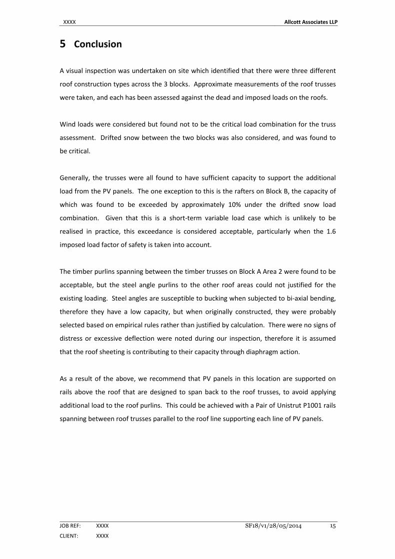
5 Conclusion
A visual inspection was undertaken on site which identified that there were three different
roof construction types across the 3 blocks. Approximate measurements of the roof trusses
were taken, and each has been assessed against the dead and imposed loads on the roofs.
Wind loads were considered but found not to be the critical load combination for the truss
assessment. Drifted snow between the two blocks was also considered, and was found to
be critical.
Generally, the trusses were all found to have sufficient capacity to support the additional
load from the PV panels. The one exception to this is the rafters on Block B, the capacity of
which was found to be exceeded by approximately 10% under the drifted snow load
combination. Given that this is a short-term variable load case which is unlikely to be
realised in practice, this exceedance is considered acceptable, particularly when the 1.6
imposed load factor of safety is taken into account.
The timber purlins spanning between the timber trusses on Block A Area 2 were found to be
acceptable, but the steel angle purlins to the other roof areas could not justified for the
existing loading. Steel angles are susceptible to bucking when subjected to bi-axial bending,
therefore they have a low capacity, but when originally constructed, they were probably
selected based on empirical rules rather than justified by calculation. There were no signs of
distress or excessive deflection were noted during our inspection, therefore it is assumed
that the roof sheeting is contributing to their capacity through diaphragm action.
As a result of the above, we recommend that PV panels in this location are supported on
rails above the roof that are designed to span back to the roof trusses, to avoid applying
additional load to the roof purlins. This could be achieved with a Pair of Unistrut P1001 rails
spanning between roof trusses parallel to the roof line supporting each line of PV panels.

XXXX Allcott Associates LLP
JOB REF: XXXX SF18/v1/28/05/2014
CLIENT: XXXX
16
6 Rights of Originator
Allcott Associates LLP will consider the re-issue of the report in its original form to a third
party within 6 months of the original report date for an administrative fee (currently £50.00
excl VAT). Upon the lapse of a 6-month period the report can only be re-issued following a
full re-inspection, which will attract a full inspection fee.
We reserve the right to refuse copies of the report to any third party (other than those
named above). We also reserve the right to amend our opinions in the event of additional
information being made available at some future date. The Contracts (Rights of Third
Parties) Act 1999 shall not apply to this agreement.
END OF REPORT
James Bodicoat MEng, CEng, MICE, MIStructE
Associate Partner
For and on behalf of Allcott Associates LLP

XXXX Allcott Associates LLP
JOB REF: XXXX SF18/v1/28/05/2014
CLIENT: XXXX
17
7 Conditions
Structural Engineers Conditions 1.0 Inspections
A Specific Structural Inspection is restricted to visual observations of the matters, concerns, or problems stated in the report. The inspection will be undertaken externally and internally as necessary and you must provide us with access to all necessary parts including any basements and roof spaces if possible. We do not normally move heavy furniture, lift floor coverings or make exploratory holes during and inspection. If our Engineer considers that access to any area would be unsafe, or potentially unsafe, we will be unable to access such areas unless safety measures are arranged, this may incur an additional cost.
1.1 A General Structural Inspection of the structural load bearing elements does not include those aspects normally dealt within a Surveyors report, such as services, decorations, roof coverings and the like, the position of the property with respect to local amenit ies and the condition of the property with regards to dry rot, timber infestation, dampness, vermin and the like.
1.2 The structural load bearing elements normally comprise items such as the roof trusses, rafters, purlins, floor slabs, joists, beams, columns, external walls, internal walls which support other elements, foundations and the like. The inspection is limited to the main building and excludes any detached garages, outbuildings, walls, fences etc unless specifically included in the request. The report is a considered opinion of the structure at the time of the survey only.
1.3 Unless noted in the report we have not considered matters such as contaminated land, asbestos or other potentially hazardous materials, nor high alumina cement or other potentially deleterious materials.
1.4 Our report will include details of the inspection, being the condition of the property at the time of our inspection, our conclusions on the findings and our recommendations for any investigations, monitoring, repair or remedial works, or other action required.
1.5 A General Structural Inspection is not ‘A Full Building Survey’ in accordance with conditions of engagement of the Royal Institute of Chartered Surveyors (see note 1.2)
1.6 Our inspections will be carried out in a safe manner as advised by the HSE and no undue risks will be taken. Roof areas will have a head and shoulder inspection.
1.7 We do not check electrical installations or appliances as this has to be done by members of the IEE institute we will however advise if this is necessary. 1.8 We do not test gas installations or appliances as this has to be a Gas Safe registered gas engineer we will however advise if this is necessary. 1.9 We will advise if we note timber infestation however we will not check for timber infestation, as this has to be carried out by a member of the British
Wood Preserving and Damp proofing association (BWPDA). Similarly with damp this also has to be checked and reported on by a member of (BWPDA). 1.10 No opening up of areas or lifting of carpets or moving of furniture is carried out. 1.11 Roof inspections will normally be head and shoulders inspections unless specifically having been requested for a roof survey, where we require the roof to
be boarded or safe access arrangements made for the inspection. In any case old roofs will not be entered as potentially unsafe. 1.12 Where we arrange for other Contractors to carry out specialist reports we are not responsible for their content. 1.13 Where costs are quoted for remedial works these are budget costs and not fixed costs and may vary depending on a contractor’s availability and location
of works. 2.0 Investigations 2.1 Our services will be limited to an investigation of the problem(s) specified. Investigations means, and may include, archive research, interviewing persons
or organisations, making exploratory holes or excavations, opening up or taking apart, taking samples, undertaking tests and any other activities necessary to determine the extent and cause of the problem.
2.2 Investigation work may cause damage – particularly to finishes and decorations. If you request us to carry out any investigation work this will indicate to us that you have all the necessary permissions from the owners and tenants of the property for us to carry out the work. Reinstatement will be included only if specifically agreed.
2.3 Our report will include details of the investigations, our conclusions on the findings and our recommendations for any monitoring, repair or remedial works, or other action required.
3.0 Monitoring 3.1 Our services will be limited to monitoring the problem areas specified and will involve measurements and visual observations at regular intervals for a
predefined period. 3.2 Our report will include details of the monitoring, our conclusions on the results and our recommendations for further investigations, repair or remedial
works, or other action required. 4.0 Repair / Remedial Works – Design Stage 4.1 Our services may include the detailing. Scheduling and specification of repairs and remedial works as agreed, the preparation of tender documents,
obtaining of competitive tenders, reporting on the tenders and applying for Building Regulations and / or other necessary approvals. Building Regulations fess and the like will be extra.
5.0 Repair / Remedial Works – Construction Stage 5.1 Our service may include inspecting the contractor’s work on an occasional site visit basis and administering the contract. 5.2 We normally undertake site inspections at weekly intervals although the frequency may vary according to the needs and the progress of the works. 5.3 We will issue instructions to the contractor and variations to the contract as necessary. Please note that you must not instruct the contractor yourself. 5.4 We will certify progress payments and upon satisfactory completion will certify the work and the final valuation. Completion certif icates will only be
issued when all our invoices are fully paid. 6.0 Calculations 6.1 Calculations will include for a site visit wherever possible although it is possible to work from your architectural drawings however the onus for
dimensions will remain with person providing the plans. All steel beams are calculated on clear openings. Bearing length generally 150mm each side should be added to the length used.
6.2 According to your requirements, we will give structural advice on the feasibility of your proposals and will prepared structural calculations and sketch details for incorporation into your architectural drawing, for building regulations submission, and for your builders use and information.
6.3 Architectural, general arrangement or structural drawings are not normally prepared and will only be prepared if agreed in writing. Please be aware that architectural drawings are normally required for building alterations and extensions, in all but the simplest of cases.
7.0 Miscellaneous Services 7.1 The scope and any limitations to miscellaneous services will be agreed with you before commencing. 8.0 Limitations 8.1 This report is for the sole use of the person instructing the survey and cannot be passed to a third party without the consent of Allcott Associates LLP as
the content will not be guaranteed to be correct as to when the report was transferred. 8.2 This survey is only valid for 6 months from the date of the survey as stated within the report

XXXX Allcott Associates LLP
JOB REF: XXXX SF18/v1/28/05/2014
CLIENT: XXXX
18
Appendix A – Loading Calculations

XXXX Allcott Associates LLP
JOB REF: XXXX SF18/v1/28/05/2014
CLIENT: XXXX
19
Appendix B – Block A Area 1 Calculations
XXXX Allcott Associates LLP
JOB REF: XXXX SF18/v1/28/05/2014
CLIENT: XXXX
20
Appendix C – Block A Area 2 Calculations

XXXX Allcott Associates LLP
JOB REF: XXXX SF18/v1/28/05/2014
CLIENT: XXXX
21
Appendix D – Block B Calculations