roofing solutions -part three- - pdhonline.com · roofing solutions (part three) ... roofs (as well...
TRANSCRIPT

An Approved Continuing Education Provider
PDH Course C813 (2 PDH)
---------------------------------------------------------------------------------------------------------------------
ROOFING SOLUTIONS -PART Three-
Ruben A. Gomez, P.E.
2015
PDH Online | PDH Center
5272 Meadow Estates Drive Fairfax, VA 22030-6658
Phone & Fax: 703-988-0088 www.PDHonline.org
www.PDHcenter.com

www.PDHcenter.com PDHonline Course C813 www.PDHonline.org
© Ruben A. Gomez Page 2 of 30

www.PDHcenter.com PDHonline Course C813 www.PDHonline.org
© Ruben A. Gomez Page 3 of 30
ROOFING SOLUTIONS
(PART THREE)
1.0 INTRODUCTION This is the third and last part of this course on the matter of the roofing art. Roofs (as well as foundations) are not only the forgotten part of a building or house, but also their methodology and technology are quite behind from the rest of the building trades. The only exterior function of a roof is to shed rain water to protect the residents, and even that is done in a haphazard and sometimes poorly way, especially when some of that water, although unintended, gets indoors rather than out and away. While is true that nothing could be more inexpressive and dull than a flat roof, it is also true that pitched roofs can be designed to “steal the show” in an spectacular way, but even in that case a roof can be exaggerated to overwhelm the looks of a house, particularly in the case of a single story dwelling. Therefore, roofs must be carefully planned and proportioned to the size of the structure they cover. The design of a roof can be both, a geometrical and a functional challenge to the design architect, while at the same time it may represent an opportunity for him/her to show his/her knowledge of his descriptive geometry as he/she struggles to find the correct traces at the intersection of the roof slopes.

www.PDHcenter.com PDHonline Course C813 www.PDHonline.org
© Ruben A. Gomez Page 4 of 30
2.0 SINGLE OVERLAP METAL ROOFS This type of roof has gained an unexpected popularity during the last twenty years, especially for its application for re-roofing projects. It is presently offered in a variety of materials, such as, galvanized steel, zinc, tin, aluminum, stainless steel and copper. The unit price varies according to the material used, very much in the same order indicated above, from the inexpensive to the very expensive. There are certain advantages in using this type of roof that need to be considered. First, it is ideal for re-roofings because it can be applied directly over an existing fiberglass or asphalt shingle roof with a minimum of disruption, other than a cleanup of the existing surface. Second, it can be done quickly and at very competitive price if confined to the low price metals. Thirdly, the thin layer of trapped air between the new roof and the existing roof, often ¾ to 1-½ inch, helps to increase its thermal efficiency. Figure 2.1 will give the reader a good idea of what this roof is all about. The key to the numbers as they appear on the figure is as follows: Number Description (1) Metal roof sheet. (2) Wood furring: 1 x 2” or 2 x 2” depending on wind pressure as required by the local building code. (3) Metal ridge cover. (4) Rust resistant fastener. #10 x 2” is commonly used, However, its size must be determined by the design engineer in accordance with wind uplift forces (see Appendix). Section (A) as it appears in the same figure, coincidentally shows the roof ribs matching the location of the trusses or rafters below. In practice it may not happen that way since the roof panels may have ribs at 12, 16 or 24 inches apart. Even when the latter rib spacing is used, they may not match as shown in the figure. On the downside, there are some disadvantages in using this type of roof. In the first place, when low grade painted metals are used, rusting may start at an early age. Naturally, when so occurs the surface can be pressure-washed, sanded or sand-blasted and re-painted with a rust inhibiting paint. In the second place, the screws used may rust or the rubber gasket may fail. When that would happen, leaks may be prone to appear. Lastly, most of the re-roofing work we have seen in the southern states is done with very little engineering, if any. In those cases, wind up-lift forces may prove to be too much for them and may get flown away in cases of hurricanes of category II or over

www.PDHcenter.com PDHonline Course C813 www.PDHonline.org
© Ruben A. Gomez Page 5 of 30
(see Appendix). A variation to the above method of installation consists in totally removing the old shingles and roofing paper down to the bare wooden sheathing. After a thorough clean-up, apply a new layer of roofing paper (preferably 30#) and then the corrugated sheet metal directly on top and fastened with screws to the sheathing. Some roofers claim that this method produces a roof that is less noisy during heavy rains. While we believe that would be a plus to some homeowners, there are multiple downsides to this alternative. Amongst others we can mention: a) by removing the shingles and roofing paper, they need to be disposed off, thus contributing to long term pollution; b) by eliminating the wood furrings, the layer of air would be no longer there to improve thermal efficiency; c) also, by not having the buffer offered by the furrings, whatever irregularities which may exist on the sheathing could then be visually detected on the sheet metal cover. When it comes to cost, there is not much difference between the two modalities, while it is true that the latter method will save the cost of the wood furrings (please notice we have called them purlins elsewhere) plus the installation labor, but on the other hand it will require removal of the old roofing and the related dumping fees, as well as the application of the new layer of roofing paper.

www.PDHcenter.com PDHonline Course C813 www.PDHonline.org
© Ruben A. Gomez Page 6 of 30

www.PDHcenter.com PDHonline Course C813 www.PDHonline.org
© Ruben A. Gomez Page 7 of 30
3.0 STANDING SEAM METAL ROOFS Standing seam roofs were very popular in the 1940’s and 1950’s because they were simple to install and at the same time economical to afford. Since steel sheets were produced in sizes of 20 x 96 inches, the resulting seam spacing was at 16 in. on centers. For wider spacings, wider metal sheet sizes had to be ordered accordingly. The cost of standing seam roofs usually hinged on the gauge and the quality of the material used, whether it was galvanized steel, aluminum or copper. Considering that all the bending and folding had to be done at the site and mostly right on the subject roof, the gage was an important consideration. The most usual method of attachment of the roof panels was done by fastening either clips or cleats to the wooden deck, the clips were used as an alignment guide and were rolled over into the seams where they remained out of sight. Given that scenario, the spacing of those clips or cleats should have been done as a function of wind uplift forces. Figure 3.1 illustrates a slope covered by a standing seam roof. This type of roof as depicted had its limitations, in the first place, if used as conceived by its inventors it was not very suitable for coastal areas subject to violent hurricane winds, in the second place, it was somewhat vulnerable to the possibility of backed-up rain water, therefore it was only recommended for slopes of 3-½ in. per foot or steeper. This figure also depicts the anchor clip detail, a closer look at this device will reveal the reason of the former statements, there was always the danger of the folded hold to unravel under persistent wind. This figure also includes a section through the roof end condition as it was finished by a fascia of the same material as that of the roof panels. Figure 3.2 provides a graphic description of the four main steps that took the forming of the standing seam, most of that work needed to be done at the site and up on the roof itself. This figure also depicts the ridge cover as it was wrapped over the carpentry work, thus providing the shape and support of the finished product. The standing seam metal roofs were not considered to be walkable roofs. Any left-over or detail work needed had to be done by roofers only.

www.PDHcenter.com PDHonline Course C813 www.PDHonline.org
© Ruben A. Gomez Page 8 of 30

www.PDHcenter.com PDHonline Course C813 www.PDHonline.org
© Ruben A. Gomez Page 9 of 30

www.PDHcenter.com PDHonline Course C813 www.PDHonline.org
© Ruben A. Gomez Page 10 of 30
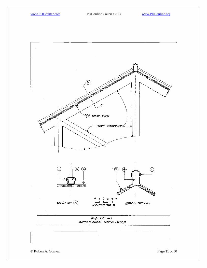
4.0 BATTEN SEAM METAL ROOFS The batten seam roof, although popular in the 1940’s and 1950’s, has fallen into disuse because of the intensity of labor and their vulnerability to hurricane winds. It had many close similarities with the standing seam roof and also most of its limitations; however, in the former case the seams were formed over wood ribs (or battens) which were securely fastened to the roof deck. This type of roof only should have been installed in those cases where there was a slope of 3 in 12 or steeper. The method of fastening was done by using clips, in a similar manner as it was detailed on the standing seam type. Similarly, this roof was not a walkable type and only roofers were allowed to walk on them. Figure 4.1 provides sectional details of its mean features. The key to the used numbers marked on the figure are as follows: Designation Number Description (1) Double hook splice (please see Fig. 3.2) (2) Roofing sheet (3) Wood core cut off from a regular 2 x 2” (4) Wood core cut off from a 2 x 4” The standard batten could have been installed easier by using 1 x 1-½” metal base channels (see Section A), which was first fastened to the wooden roof deck. Then, the battens were attached in place by using screws driven from both sides.
www.PDHcenter.com PDHonline Course C813 www.PDHonline.org
© Ruben A. Gomez Page 11 of 30

www.PDHcenter.com PDHonline Course C813 www.PDHonline.org
© Ruben A. Gomez Page 12 of 30
5.0 SPECIALTY ROOFS This section is dedicated to cover those cases where the roofing finish mostly needs to be applied on concrete surfaces. For that purpose we have selected two classic cases, a folded plate and a vaulted roof. Both folded plates and vaults are generally part of long span structures and both need adequate drainage treatment for any accumulation of water near the center of the span may put them in jeopardy. When it comes to snow, there is no alternative but provide for a snow load according to the maximum expected precipitation according to the geographic location and the local code. In the case of rain, the most reasonable solution is to provide the valleys with a slope by using a light concrete filler in such a way to attain a minimum slope of 1/8 in. per foot. In cases of expected large deflections, that slope may need to be increased to ¼ in. per foot. Here again is the usual contradicting paradigm: the longer the span the larger the deflection, the larger the deflection the deeper the filler, the deeper the filler the larger the load, the larger the load the larger the deflection, and so on. Therefore, is up to the design engineer to find the “happy medium” of where to draw the line. Figure 5.1 illustrates the case of a reinforced concrete folded plate with a center-to-center span of 40 ft. and a total width of 50 feet including the cantilevers. This structure was used as a parking garage with 10 ft. wide bays suitable for automobiles and pick-up trucks. In order to dispose of the rain water in a speedy manner and at the same time prevent the undesirable ponding, certain provisions had to be made. To lower the horizontal shear stresses at the joint, the structural engineer had provided a hunch (see Section A). By reviewing his structural computations we also found that the calculated deflection in the middle of the span had been determined as 0.74 in. (say ¾ in.). The reader may conclude that the referred folded plate (1), if left unfinished, would have held water in the middle of the span, therefore, it was necessary to create a high point (H.P.) in the middle with a thickness of 6 inches and reduce it gradually down to zero at the end of the folded plate. In order to save weight, a filler (2) was conceived by using a low strength mix of lightweight concrete. To avoid the typical mildewed water marks, another provision was made: a dam panel (3) was erected at the end of the valley and a scupper (4) was installed to drain the accumulated water. The entire surface of the folded plate was treated with two applications of an approved white elastomeric coating. One of the problems of concrete when used as a roof (very particularly), is its propensity to develop cracks due to several known causes such as: shrinkage, creep and/or temperature differentials. One good practice in cases such as the herein described is to return sometime between 6 months to a year and fix all observed cracks by first grinding lightly the area, second applying a fresh coat of an elastomeric emulsion and embed a wide enough strip of fiberglass mesh and an hour

www.PDHcenter.com PDHonline Course C813 www.PDHonline.org
© Ruben A. Gomez Page 13 of 30
later apply a second coat of the same emulsion. A sure and guaranteed solution to avoid the insidious appearance of undesirable cracks on the surface of a concrete slab is to switch from a “hard slab” to a “soft slab” concept by using post-tensioning cables instead of just regular reinforcing bars. Figure 5.2 comes to show a circular vaulted roof in similar circumstances as the folded plate described above. Here again, (1) refers to the specified structural concrete of which the vaults were made of, while (2) is the lightweight mix used to produce the slope necessary for an effective runoff. A dam panel (3) was again used to contain the flow of rain water and directed through a scupper (4) of a diameter large enough to drain the water volume accumulated as result of the largest expected rainfall in a hundred year occurrence. All other considerations made as part of the narrative of the folded plates, apply here to this case as well.

www.PDHcenter.com PDHonline Course C813 www.PDHonline.org
© Ruben A. Gomez Page 14 of 30

www.PDHcenter.com PDHonline Course C813 www.PDHonline.org
© Ruben A. Gomez Page 15 of 30

www.PDHcenter.com PDHonline Course C813 www.PDHonline.org
© Ruben A. Gomez Page 16 of 30
6.0 THE TREES AND YOUR ROOF We all have heard of how wonderful is to have one’s house surrounded by trees, your house gets cooler in the Summer while saving money on one’s power bill. Additionally and truly, well planned trees will enhance the look of your house, make it much more attractive and cozy, and may even tend to increase its value. It would be wonderful if the story would stop there, but there is more, much more but on the downside. If trees were allowed to grow unattended and uncontrolled, a lot of bad things could happen. They would attract nice birds and undesirable birds, they would also attract squirrels and rats. If those trees happened to be hanging over your roof, those animals will try to get in your house by vents, transoms and cracked soffits. In case of high winds, hurricane or tornadoes, those adorable trees may fall over your roof and destroy your largest asset, thus creating an unnecessary turmoil in your life. True, your house will get cooler indeed, but also colder in the winter. Without the benefit of the solar rays, your house will have a tendency to host mold growth and mildew. Lastly, do not forget that most trees will drop their leaves in the fall and some of those leaves will end up on your roof. If you do not remove them they will decompose and hold humidity, which at the same time, will accelerate the rapid decay of your roof. We do not advocate for anyone to have a property totally barren of trees and shrubs, but they must be kept under control. Therefore, when you plant new trees in your front or backyards keep in mind that eventually they will grow large, so keep them away from your house for a distance equal to the maximum expected adult height. If you have just bought a house with a yard full of trees, make a sketch of the property, locate all trees by dimension. First, cut back all tree limbs that project over your roof and remove all trees that are in the proximity of the house and whose trunks are within thirty feet off the roof overhangs and patios. Trees adjacent to your house will not only pose a threat in case of high winds, but also, their roots will eventually end up cracking your ground floor slab and your basement walls. Do not allow any shrubs against the exterior walls of the house, for they will sponsor insect colonies, amongst others, yellow jacket wasps, carpenter ants and termites, which you definitely don’t want in your house or in your attic. Consequently, the best advise we can offer is keep the trees within your property under control, while you enjoy the greenery, the shade and the breeze without having to worry about the potential inconveniences to your roof and to your pocket.

www.PDHcenter.com PDHonline Course C813 www.PDHonline.org
© Ruben A. Gomez Page 17 of 30
7.0 ROOF REPAIRS This section may appear to many as out of place in the sequential narrative of this course, however, we have done it on purpose by placing it close to the end for one reason and one reason only, roof repairs may seem as a secondary activity to an accomplished roofer; further, such perception may be even more reinforced when we often see some unqualified persons trying to do roof repair work by themselves. However, we should not forget that a good roof may become a failure case when shoddily repairs are made on it. It is common knowledge dictated by common sense, that there are parts in a roof that are more prone to leaks than others. The following are part of such group: Chimneys Skylights Scuttles Valleys Vent pipes Vertical-to-horizontal intersections Cracked parapets. On the other hand, leaks through the slope fields although possible, are much less frequent. By saying so, it does not mean that they should be ignored or minimized in the final analysis. The first word of warning to the inexperienced roofer-to-be is that trying to detect the point of entry of rain water may be a puzzle that needs some well guided method of discovery. For instance, in the case of watershed roofs with a diversity of slopes, when examining a water leak that appears in a certain location on the ceiling. That does not mean that the point of entry is directly through the roof and roofing directly above. While it may, most probably it is not. Naturally, the next step is for the examiner to climb into the attic space directly above the wet ceiling and start to look for a wet roof deck, once he finds it, he has found the point of entry, but again, he may not. His next step should be climbing over to the roof and thoroughly inspect it, always keeping in mind that water runs downhill. In some cases the entry point may be a few feet away uphill (or upstream, whichever way you prefer to call it). Then mark it up and conservatively decide how much of the existing roof you should replace. Figure 7.1 illustrates a common case and a good example of a random roof leak and the way to proceed in locating it and also how to proceed in repairing it. Obviously, before we can attempt to repair a roof, the water entry port has to be located. In the first place, we will address first the pitched roofs and immediately after, the flat roofs. PITCHED (WATERSHED) ROOFS

www.PDHcenter.com PDHonline Course C813 www.PDHonline.org
© Ruben A. Gomez Page 18 of 30
In order to locate the water entry port, we need to know how a leak is formed and transmitted through the different roof parts and components. As a roof ages, both shingles and tar paper will gradually dry up and crack until they become ineffective and allow a water entry port (1)*, from there the rainwater will roll down to the nearest lower joint in the sheathing (2) thus accessing the attic space. Once that takes place, the water will drip over saturating the insulation layer (3) and finding a joint in the ceiling (4) and becoming noticeable to the house residents. That is why this type of leaks are so deceiving, the natural tendency of the layman is to look up following an imaginary plumb line (5), while the experienced roof consultant will look five of six feet uphill. While the scenario illustrated in the figure solves the puzzle on the vertical plane of the graphic, there is nothing precluding the water to also travel sidesway, left or right of the point of entry (1). --------------------------------------------------------------------------------------------------------------------- *It is not to say that an entry port could not be created in a brand new roof by either a wind storm, a flying object or a hail storm. --------------------------------------------------------------------------------------------------------------------- Once the point of entry is located, the next step is to proceed with the repairs. The entry point should be marked carefully and the old felt and shingles removed in a patching area of approximately 4 x 6 ft. as shown on the figure. We also recommend that when the point of entry (1) is within 4 ft. (H) of the ridge, that the patch be extended all the way to it. Once the patching up is complete, the repair person should proceed to remove all the wet insulation and discard it. For once the insulation is wet, it loses most of its thermal efficiency. FLAT ROOFS When a leak has taken place in a flat roof, you may look directly above, but always keeping in mind that in flat roofs water may also travel for a few feet within the roof layers. Once on top of the roof, you may examine any point of standing water and look for a punctured membrane, detached joints or open fish mouthing. Before any repair attempts are made, all water must be removed and the area carefully cleaned and dried up. Follow the standard procedure described elsewhere in this course. Those roofers or roofing consultants working in the State of Florida should be cognizant of the fact that the Florida Building Code (FBC) has certain provisions that may apply depending on the extent of the repairs. The 2014 FBC, Section 708.1 stipulates that: No more than 25 percent of the total roof area or roof section of any existing building shall be repaired, replaced or recovered in any 12 months period, unless the entire roofing system or roof section conforms to the requirements of this code. Meaning that, in the case of those old roofs which were installed before the adoption of the FBC, if the needed repair is more than

www.PDHcenter.com PDHonline Course C813 www.PDHonline.org
© Ruben A. Gomez Page 19 of 30
25% of the total roof area, then, the entire roof may have to be made in conformance and be replaced in its entirety. The reader may be interested in knowing that there is a family of products commonly known as elastomeric roof coatings which may become handy in the repair of roofs. They can be applied by brush or rollers. When properly applied and adequately cured, the coating becomes a continuous film. Although it is not recommended for shingle roofs, it would work on most other roofs with enough continuity, especially where and when the components are not subject to excessive movement. Of all roofs, concrete roofs are the best candidates for such application.

www.PDHcenter.com PDHonline Course C813 www.PDHonline.org
© Ruben A. Gomez Page 20 of 30

www.PDHcenter.com PDHonline Course C813 www.PDHonline.org
© Ruben A. Gomez Page 21 of 30
8.0 THE ROOF OF THE FUTURE The purpose of this section is to offer a glimpse to what may be ahead in store for us when it comes to roof design and construction. We have already indicated elsewhere that roof material manufacturing technology is to some extent advanced, however, roof material application methodology is somewhat and somewhere in the dumps. In order to approach the task of improving the roofs of the present, we first have to reduce the problem by breaking it down in three areas of importance: a) function, b) methodology, and c) aesthetics. The indications we have at this moment is that some efforts are being made on the part of certain governmental agencies to develop technologies geared to improve some of the areas of concern indicated above. From their vantage point, they seem to believe that the roof of the future should follow one of two schools of thought, the first one predicates on the fact that roofs should be driven as part of the energy efficiency concept, even if that means a loss of elegance and beauty, while the second school seems to be directed to utilize to the maximum the concept of mechanized versatility to likely reaching results oriented in the opposite direction. As it seems, the concept of functionality is being left to rest on its own by the moment. First, let us examine what can be perceived as the “green” roof experience. In that effort has emerged an unexpected host that seems to be only interested in energy efficiency technology. That host is probably one of the largest energy users in the United States, the Department of Defense, also known for its initials “DoD”. They have been seriously involved in the development of a prototype roof that promotes energy efficiency above anything else, with the hope that the final version could be replicated for new housing, retrofitting single homes or multifamily projects. The proposed idea appears to be consisting of five layers. The first layer is formed by metal purlins fastened to either an existing roof to be retrofitted or in the case of new construction, to the new roof structure. Fastened to those purlins would be second layer consisting of a self regulating solar thermal system providing for a large portion of the house’s (or building) energy demand. The third layer would be an R-19 insulation, radiant barrier and thermal resistance system.
A fourth layer will be a 24 gauge “cool” painted metal roof. The top and final layer would consist of an integrated photovoltaic plate. As the retrofitted metal roof is installed over the existing roof, it creates a cavity where the “solar thermal system” would be installed, thus facilitating the cooling of both air and water for the house or building. Other direct and “bonus” benefits brought about are: 1- The solar reflecting coated cool metal roofing would save some 25% of the summer cooling energy costs.

www.PDHcenter.com PDHonline Course C813 www.PDHonline.org
© Ruben A. Gomez Page 22 of 30
2- The solar thermal system would provide preheated water for use in the house or building. In addition, that heated water could also be used for space heating just with the addition of a heat exchanger. 3- One additional benefit not mentioned until now is that metal gutters would also be integrated with the system to collect rainwater suitable for irrigation and toilet flushing. As the reader has probably detected, DoD proposal does not improve on the actual roof performance or aesthetics, but does provide many energy conservation and generation features. There are other proposals that add a great deal of sophistication to the roof function. Figure 8.1 introduces the idea of a retractable and telescoping roof which can be opened almost fully, to produce a being outdoors feeling on the occupant. This type of roof can be made totally automatic and/or remote controlled to meet the taste of the demanding and of the affluent. One aspect for the design engineer to consider when dealing with this type of roof is the common enemy of all roofs: wind lateral pressure and uplift. As the telescoping sections need to be mounted on wheels (2), the system must be designed in such a way that those wheels have an effective restraint against uplift forces. Section A in the same figure shows a multiple base channel (1) with enough rails to accommodate as many retractable sections as the design calls for. The illustrated case depicts three movable sections and one fixed at the end, on both sides. Lastly, it is important to notice that this is not the type of roof that can remain ignored or unattended as those shown at the beginning of this part of the course; it often would need cleaning, oiling, adjustments and repairs. Therefore, there would be frequent foot traffic around it, which is why we have called for the adjacent flat roof to be walkable as indicated in the figure. In addition to the sliding section type described above, there also is a circular type of roof where the lower half of the roof rotates 180 degrees exposing half of the covered area to the direct effect of the sun rays and outdoors breeze. Such system is operable under the same conditions described above.

www.PDHcenter.com PDHonline Course C813 www.PDHonline.org
© Ruben A. Gomez Page 23 of 30

www.PDHcenter.com PDHonline Course C813 www.PDHonline.org
© Ruben A. Gomez Page 24 of 30
CONCLUSION
We have reached the end of this course in its three parts, if the reader has followed the directions, concepts and ideas covered in the material offered, he should be very well equipped to tackle any problem or condition presented to him/her and be ready to offer a pragmatic and practical solution. Anybody engaged into the solution of roof problems should not lose sight of the fact that the roof function is to provide cover against the elements in a way that is water-tight, while it is strong enough to resist the wind pressure of an obstinate hurricane. Residents in the Caribbean islands sleep well under the cover and protection of their four-inch (or more) reinforced concrete roofs, while we in the continental U.S. have to do it under the cover of ½ inch roof sheathing. By the way, our intention was not to make you laugh; for we still remember a certain incident that took place in the mid nineteen-seventies, when in the middle of the night the residents of a regular house in the City of Hialeah were suddenly awakened by an uncommon loud noise that seemed to come from their own dining room. We broke the paragraph here to give the reader a little time to think about it. The noise we referred to above came from a five-pound block of ice that punched through the roof sheathing plus the ½ inch gypsum board ceiling and landed on their dinning roof table. If you are thinking of a hailstone, it was not. It came from the belly of a landing Jumbo Jet that had a leak in one of its sanitary holding tanks. That iced human waste block, although just five pounds, had developed in its fall a large enough momentum to punch through the roof deck and could well have killed the person sleeping ten feet away in the next room. In our perpetual search for economy and ease, somehow and somewhere in the shuffle we seem to have forgotten safety. Some argue that for as long as we have insurance available, we can stretch safety to the limit. What do you think? At any rate, we hope that this course has captured the reader’s imagination and has challenged his/her ingenuity, to the point that he/she engages some of his/her time in the pursuit of a better roof.

www.PDHcenter.com PDHonline Course C813 www.PDHonline.org
© Ruben A. Gomez Page 25 of 30
APPENDIX
1- BACK TO THE PAST
Our modern man can rightfully claim enormous gains in the areas of medicine, pharmacology, astronomy, astrophysics, cosmology, biology, engineering, electronics, computer sciences, etc. On the other hand, there are other areas where perceptible advances seem to be falling behind. In relative terms, building roof technology is one of those areas where the knowledge gains are lagging behind for at least in a hundred years. While it is true that when it came to roofing materials, there are some gains that should not be denied. On the other hand, when it comes to the manner of how those materials are used and applied to achieve a durable water tight roofing coverage, the progress has been not any better than mediocre. With the deliberate intention to show the contrast, we have gone behind in time some five hundred years or so, to the era of the early inhabitants of this continent and dug up in the history books the manner in which they handled the problem of getting a roof over their heads, in doing so, we have realized the fact that we are not as advanced as we should be. THE ARAWAK INDIANS OF THE CARIBBEAN The attached graphics show a circular hut with circular walls that were at first put together with tree logs and royal palm boards, evolving later to the limestone masonry which we have seen in a previous part of this course. The roof of the unit was solved by laying inclined hard-wood logs from the center of the circle to the perimeter walls; on top of that they would lay tree limbs following a concentric pattern. The roofing coverage was attained by attaching kanah tree branches “a” as indicated in the figure insert “b” of the corresponding graphic. All the required connections were made with vines or less frequently with threaded animal rawhide. The performance of the Kanah roof was quite satisfactory during the first rain of the season, as rain continued during the following days of the monsoon, the fibers became saturated and some leaks were about to appear within the enclosed space. This type of dwelling was suitable to the Arawak Indians who contrary to their counterparts in the northern continent, were not of the nomadic type. Their main staples came from the agricultural endeavor, they planted bananas, plantains, cocoa and tuberous roots, such as “yuca” roots and sweet potatoes. They also grew tobacco for their traditional rituals. The kanah palm has always been a very abundant tropical palm which still can be seen in most of the Caribbean islands, large and small. In normal conditions the “Kanah roof” had a service life of some 10 years, and the re-roofing process was done the very same

www.PDHcenter.com PDHonline Course C813 www.PDHonline.org
© Ruben A. Gomez Page 26 of 30
way as the original roofing by packing the branches thick over the cross limbs. As the roof aged and got progressively leaky, they removed the branches from the old roof, which usually went to feed up the fire pile.

www.PDHcenter.com PDHonline Course C813 www.PDHonline.org
© Ruben A. Gomez Page 27 of 30

www.PDHcenter.com PDHonline Course C813 www.PDHonline.org
© Ruben A. Gomez Page 28 of 30
THE AMERICAN SIOUX INDIAN TIPI Contrary to the Arawak Indians, the Sioux were highly nomadic people who had to follow the migrations of the buffalos which were not only their daily staple but also the source of material for all of their needs. Since the lives of the Sioux were dependent on the buffalo, they needed to move according to the migration patterns of the animal which was their main source of food. Therefore, their dwellings had to be removable at a moment’s notice and easily transportable by horse. The Sioux tipi consisted of several main long poles (somewhere between 24 to 30 feet long). As indicated in the enclosed graphic, the main poles were arranged well packed on the ground and bound on the light end (see insert “a“). Then the poles were stood up and slanted in a circular outline to form a figure similar to a cone (“c“). Some additional shorter poles were added to increase strength and reduce the spacings in the lower parts of the framing. After the frame was set in a stable position and a firm manner, they would drape a buffalo hide covering made out of some twenty skins (see insert “b“). A hole was left at the very top as an exhaust exit for the smoke coming from the indoors cooking and heating pile. The entrance to the tipi was usually aligned with the main seam of the hide covering. Such opening was furnished with closable flaps. More often than not, the entrance opening was also provided with a rudimentary canopy to cover the entrance from the rain and wind. The tipi was strong enough to resist the frequent western winds sweeping across the flat lands of the Midwest and was water-tight enough to provide shelter from the seasonal rains, yet, easily removable to satisfy the needs of such migratory people.

www.PDHcenter.com PDHonline Course C813 www.PDHonline.org
© Ruben A. Gomez Page 29 of 30

www.PDHcenter.com PDHonline Course C813 www.PDHonline.org
© Ruben A. Gomez Page 30 of 30
2- HURRICANE CATEGORIES Although all hurricanes are dangerous, some are more than others. In order to make comparisons an easier task, in hurricane forecasting there are five categories in terms of the disaster potential to be expected from the storms. Below there is a reproduction of the commonly accepted and used Saffir-Simpson Scale: Category Wind Speed (MPH) 1 74-95 2 96-110 3 111-130 4 131-155 5 >155 3- WOOD SCREWS We will limit our description to screws within gages 6 through 10 only, other gages are of little use in nailable roofs. Also, we will proceed under the following presumptions: a) screws were driven by using automatic rotary drills, b) pre-bored holes were not used, c) that the screws were selected of sufficient gage to cause failure in the wood rather than in the screw shank, and d) that the lumber used was either coast type Douglas Fir or Southern Pine with a specific gravity between 0.50 and 0.60.
ALLOWABLE WITHDRAWAL LOADS Screw Gage Shank Diameter (in) Load (lbs)* 6 0.14 150 8 0.16 170 10 0.19 205 *Per inch of penetration. END