rooftop (impervious surface) disconnectionrooftops and/or onlot residential impervious surfaces -...
TRANSCRIPT
VA DCR DEQ STORMWATER DESIGN SPECIFICATION NO. 1 ROOFTOP DISCONNECTION
Version 2.0, April 1, 2013 Page 1 of 19
VIRGINIA DCR DEQ STORMWATER DESIGN SPECIFICATION No. 1
ROOFTOP (IMPERVIOUS SURFACE) DISCONNECTION
VERSION 2.0 July 1, 2013
SECTION 1: DESCRIPTION
This strategy involves managing runoff close to its source by intercepting, infiltrating, filtering, treating or reusing it as it moves from the impervious surface to the drainage system. Two kinds of disconnection are allowed: (1) simple disconnection, whereby residential or small commercial rooftops and/or on-lot residential impervious surfaces are directed to pervious areas, and (2) disconnection leading to an alternate runoff reduction practice(s) adjacent to the roof or small residential impervious area (Figures 1.1 & 1.2). Alternate disconnection practices can use less space than simple disconnection and can enhance runoff reduction rates. Applicable practices include: • Soil compost-amended filter path [Stormwater (SW) Design Spec 4] • Infiltration by micro-infiltration practice (dry wells or french drains, SW Design Spec 8) • Filtration by rain gardens or micro-bioretention (SW Design Spec 9) • Storage and reuse with a cistern or other vessel (rainwater harvesting, SW Design Spec 6) • Storage and release in a stormwater planter. (SW Design Spec 9, Appendix A)
VA DCR DEQ STORMWATER DESIGN SPECIFICATION NO. 1 ROOFTOP DISCONNECTION
Version 2.0, April 1, 2013 Page 2 of 19
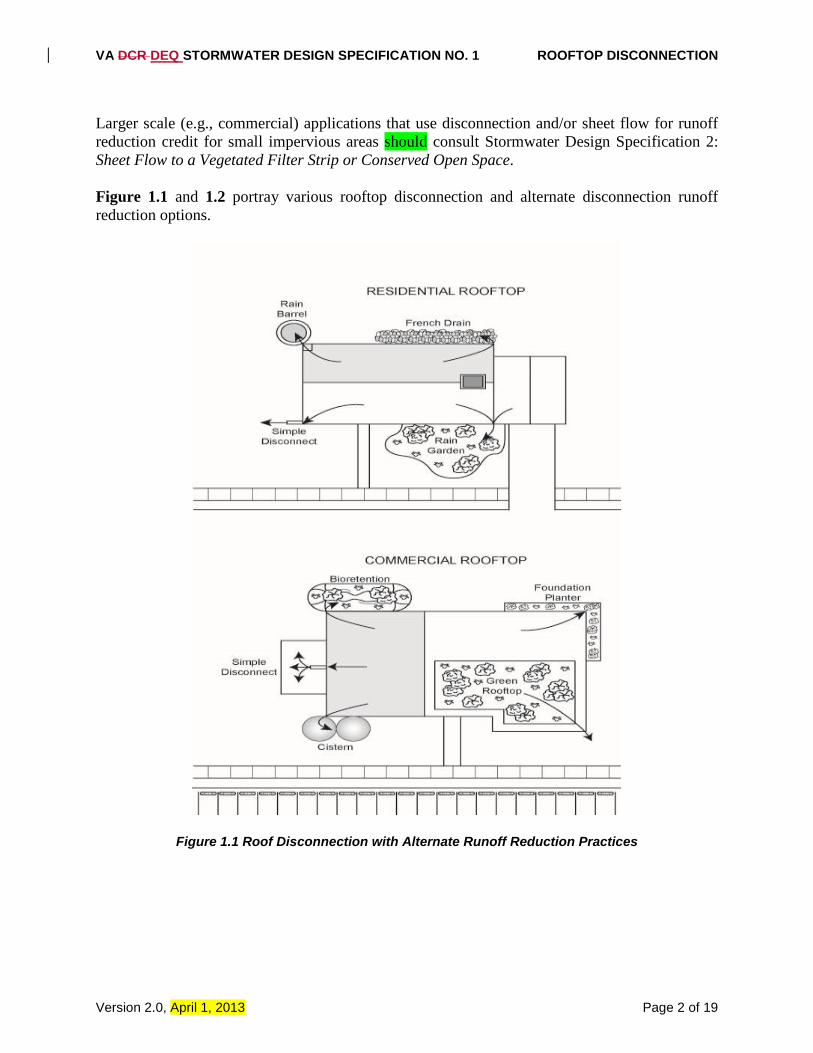
Larger scale (e.g., commercial) applications that use disconnection and/or sheet flow for runoff reduction credit for small impervious areas should consult Stormwater Design Specification 2: Sheet Flow to a Vegetated Filter Strip or Conserved Open Space. Figure 1.1 and 1.2 portray various rooftop disconnection and alternate disconnection runoff reduction options.
Figure 1.1 Roof Disconnection with Alternate Runoff Reduction Practices
VA DCR DEQ STORMWATER DESIGN SPECIFICATION NO. 1 ROOFTOP DISCONNECTION
Version 2.0, April 1, 2013 Page 3 of 19
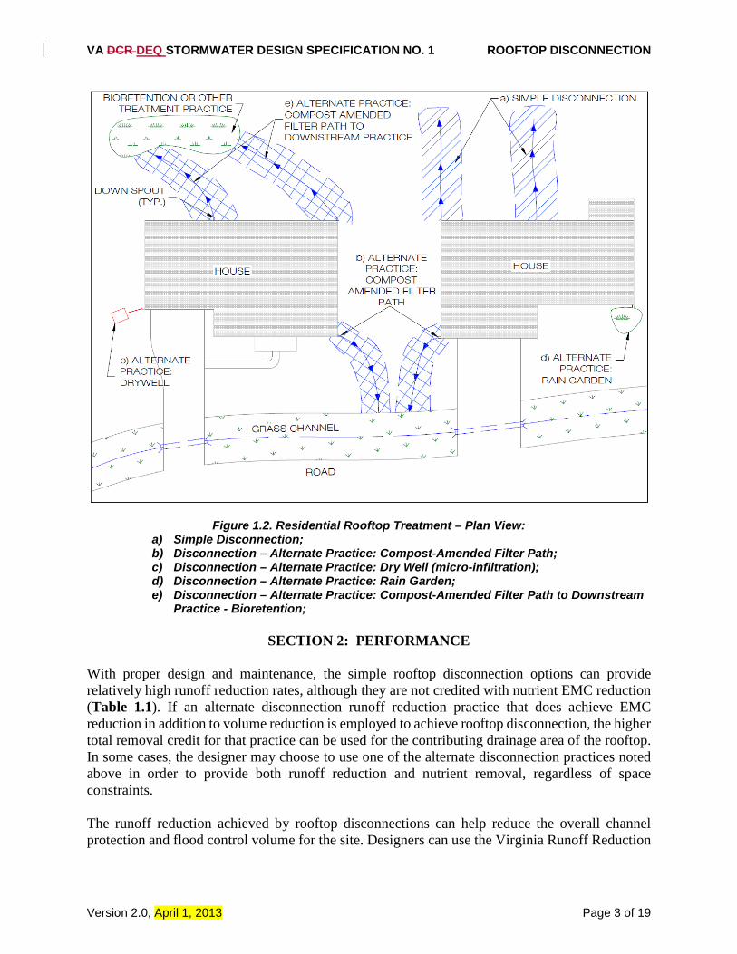
Figure 1.2. Residential Rooftop Treatment – Plan View: a) Simple Disconnection; b) Disconnection – Alternate Practice: Compost-Amended Filter Path; c) Disconnection – Alternate Practice: Dry Well (micro-infiltration); d) Disconnection – Alternate Practice: Rain Garden; e) Disconnection – Alternate Practice: Compost-Amended Filter Path to Downstream
Practice - Bioretention;
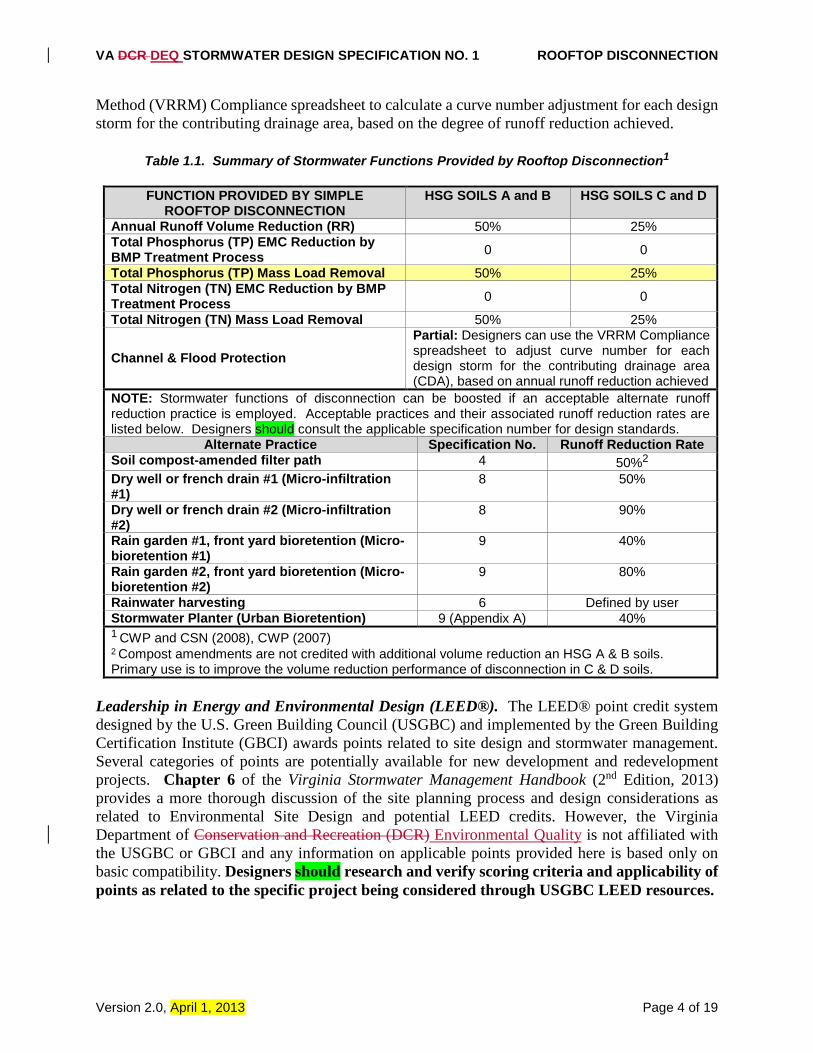
SECTION 2: PERFORMANCE With proper design and maintenance, the simple rooftop disconnection options can provide relatively high runoff reduction rates, although they are not credited with nutrient EMC reduction (Table 1.1). If an alternate disconnection runoff reduction practice that does achieve EMC reduction in addition to volume reduction is employed to achieve rooftop disconnection, the higher total removal credit for that practice can be used for the contributing drainage area of the rooftop. In some cases, the designer may choose to use one of the alternate disconnection practices noted above in order to provide both runoff reduction and nutrient removal, regardless of space constraints. The runoff reduction achieved by rooftop disconnections can help reduce the overall channel protection and flood control volume for the site. Designers can use the Virginia Runoff Reduction
VA DCR DEQ STORMWATER DESIGN SPECIFICATION NO. 1 ROOFTOP DISCONNECTION
Version 2.0, April 1, 2013 Page 4 of 19
Method (VRRM) Compliance spreadsheet to calculate a curve number adjustment for each design storm for the contributing drainage area, based on the degree of runoff reduction achieved.
Table 1.1. Summary of Stormwater Functions Provided by Rooftop Disconnection1
FUNCTION PROVIDED BY SIMPLE ROOFTOP DISCONNECTION
HSG SOILS A and B HSG SOILS C and D
Annual Runoff Volume Reduction (RR) 50% 25% Total Phosphorus (TP) EMC Reduction by BMP Treatment Process 0 0
Total Phosphorus (TP) Mass Load Removal 50% 25% Total Nitrogen (TN) EMC Reduction by BMP Treatment Process 0 0
Total Nitrogen (TN) Mass Load Removal 50% 25%
Channel & Flood Protection Partial: Designers can use the VRRM Compliance spreadsheet to adjust curve number for each design storm for the contributing drainage area (CDA), based on annual runoff reduction achieved
NOTE: Stormwater functions of disconnection can be boosted if an acceptable alternate runoff reduction practice is employed. Acceptable practices and their associated runoff reduction rates are listed below. Designers should consult the applicable specification number for design standards.
Alternate Practice Specification No. Runoff Reduction Rate Soil compost-amended filter path 4 50%2 Dry well or french drain #1 (Micro-infiltration #1)
8 50%
Dry well or french drain #2 (Micro-infiltration #2)
8 90%
Rain garden #1, front yard bioretention (Micro-bioretention #1)
9 40%
Rain garden #2, front yard bioretention (Micro-bioretention #2)
9 80%
Rainwater harvesting 6 Defined by user Stormwater Planter (Urban Bioretention) 9 (Appendix A) 40% 1 CWP and CSN (2008), CWP (2007) 2 Compost amendments are not credited with additional volume reduction an HSG A & B soils. Primary use is to improve the volume reduction performance of disconnection in C & D soils.
Leadership in Energy and Environmental Design (LEED®). The LEED® point credit system designed by the U.S. Green Building Council (USGBC) and implemented by the Green Building Certification Institute (GBCI) awards points related to site design and stormwater management. Several categories of points are potentially available for new development and redevelopment projects. Chapter 6 of the Virginia Stormwater Management Handbook (2nd Edition, 2013) provides a more thorough discussion of the site planning process and design considerations as related to Environmental Site Design and potential LEED credits. However, the Virginia Department of Conservation and Recreation (DCR) Environmental Quality is not affiliated with the USGBC or GBCI and any information on applicable points provided here is based only on basic compatibility. Designers should research and verify scoring criteria and applicability of points as related to the specific project being considered through USGBC LEED resources.
VA DCR DEQ STORMWATER DESIGN SPECIFICATION NO. 1 ROOFTOP DISCONNECTION
Version 2.0, April 1, 2013 Page 5 of 19
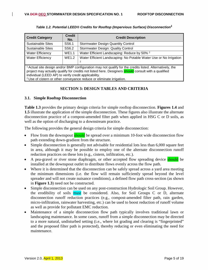
Table 1.2. Potential LEED® Credits for Rooftop (Impervious Surface) Disconnection1
Credit Category Credit No. Credit Description
Sustainable Sites SS6.1 Stormwater Design Quantity Control Sustainable Sites SS6.2 Stormwater Design: Quality Control Water Efficiency WE1.1 Water Efficient Landscaping: Reduce by 50% 2 Water Efficiency WE1.2 Water Efficient Landscaping: No Potable Water Use or No Irrigation
2 1 Actual site design and/or BMP configuration may not qualify for the credits listed. Alternatively, the project may actually qualify for credits not listed here. Designers should consult with a qualified individual (LEED AP) to verify credit applicability. 2 Use of cistern or other conveyance reduce or eliminate irrigation.
SECTION 3: DESIGN TABLES AND CRITERIA
3.1. Simple Rooftop Disconnection Table 1.3 provides the primary design criteria for simple rooftop disconnection. Figures 1.4 and 1.5 illustrate the application of the simple disconnection. These figures also illustrate the alternate disconnection practice of a compost-amended filter path when applied in HSG C or D soils, as well as the option of discharging to a downstream practice. The following provides the general design criteria for simple disconnection:
• Flow from the downspout should be spread over a minimum 10-foot wide disconnection flow path extending down-gradient from the structure.
• Simple disconnection is generally not advisable for residential lots less than 6,000 square feet in area, although it may be possible to employ one of the alternate disconnection runoff reduction practices on these lots (e.g., cistern, infiltration, etc.).
• A pea-gravel or river stone diaphragm, or other accepted flow spreading device should be installed at the downspout outlet to distribute flows evenly across the flow path.
• Where it is determined that the disconnection can be safely spread across a yard area meeting the minimum dimensions (i.e. the flow will remain sufficiently spread beyond the level spreader and will not create nuisance conditions), a defined flow path cross-section (as shown in Figure 1.3) need not be constructed.
• Simple disconnection can be used on any post-construction Hydrologic Soil Group. However, the erodibility of soils must be considered. Also, for Soil Groups C or D, alternate disconnection runoff reduction practices (e.g., compost-amended filter path, rain garden, micro-infiltration, rainwater harvesting, etc.) can be used to boost reduction of runoff volume as well as provide for pollutant EMC reduction.
• Maintenance of a simple disconnection flow path typically involves traditional lawn or landscaping maintenance. In some cases, runoff from a simple disconnection may be directed to a more natural, undisturbed setting (i.e., where lot grading and clearing is “fingerprinted” and the proposed filter path is protected), thereby reducing or even eliminating the need for maintenance.
VA DCR DEQ STORMWATER DESIGN SPECIFICATION NO. 1 ROOFTOP DISCONNECTION
Version 2.0, April 1, 2013 Page 6 of 19
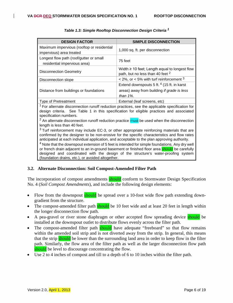
Table 1.3: Simple Rooftop Disconnection Design Criteria 1
DESIGN FACTOR SIMPLE DISCONNECTION
Maximum impervious (rooftop or residential impervious) area treated
1,000 sq. ft. per disconnection
Longest flow path (roof/gutter or small residential impervious area)
75 feet
Disconnection Geometry Width ≥ 10 feet; Length equal to longest flow path, but no less than 40 feet 2
Disconnection slope < 2%, or < 5% with turf reinforcement 3
Distance from buildings or foundations Extend downspouts 5 ft. 4 (15 ft. in karst areas) away from building if grade is less than 1%.
Type of Pretreatment External (leaf screens, etc) 1 For alternate disconnection runoff reduction practices, see the applicable specification for design criteria. See Table 1 in this specification for eligible practices and associated specification numbers. 2 An alternate disconnection runoff reduction practice must be used when the disconnection length is less than 40 feet. 3 Turf reinforcement may include EC-3, or other appropriate reinforcing materials that are confirmed by the designer to be non-erosive for the specific characteristics and flow rates anticipated at each individual application, and acceptable to the plan approving authority. 4 Note that the downspout extension of 5 feet is intended for simple foundations. Any dry well or french drain adjacent to an in-ground basement or finished floor area should be carefully designed and coordinated with the design of the structure’s water-proofing system (foundation drains, etc.), or avoided altogether.
3.2. Alternate Disconnection: Soil Compost-Amended Filter Path The incorporation of compost amendments should conform to Stormwater Design Specification No. 4 (Soil Compost Amendments), and include the following design elements: • Flow from the downspout should be spread over a 10-foot wide flow path extending down-
gradient from the structure. • The compost-amended filter path should be 10 feet wide and at least 20 feet in length within
the longer disconnection flow path. • A pea-gravel or river stone diaphragm or other accepted flow spreading device should be
installed at the downspout outlet to distribute flows evenly across the filter path. • The compost-amended filter path should have adequate “freeboard” so that flow remains
within the amended soil strip and is not diverted away from the strip. In general, this means that the strip should be lower than the surrounding land area in order to keep flow in the filter path. Similarly, the flow area of the filter path as well as the larger disconnection flow path should be level to discourage concentrating the flow.
• Use 2 to 4 inches of compost and till to a depth of 6 to 10 inches within the filter path.
VA DCR DEQ STORMWATER DESIGN SPECIFICATION NO. 1 ROOFTOP DISCONNECTION
Version 2.0, April 1, 2013 Page 7 of 19
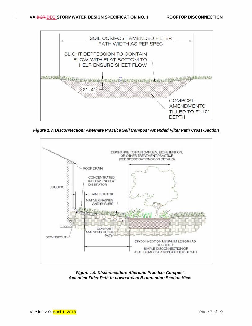
Figure 1.3. Disconnection: Alternate Practice Soil Compost Amended Filter Path Cross-Section
Figure 1.4. Disconnection: Alternate Practice: Compost Amended Filter Path to downstream Bioretention Section View
VA DCR DEQ STORMWATER DESIGN SPECIFICATION NO. 1 ROOFTOP DISCONNECTION
Version 2.0, April 1, 2013 Page 8 of 19
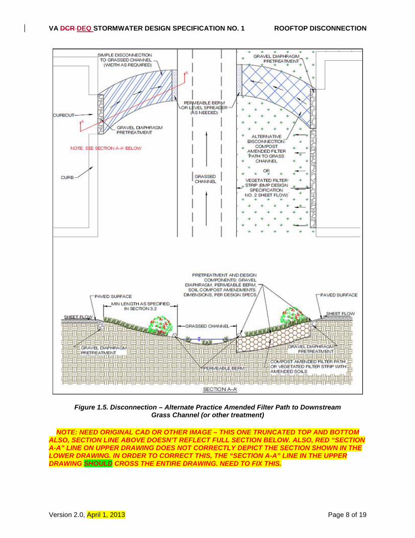
Figure 1.5. Disconnection – Alternate Practice Amended Filter Path to Downstream Grass Channel (or other treatment)
NOTE: NEED ORIGINAL CAD OR OTHER IMAGE – THIS ONE TRUNCATED TOP AND BOTTOM
ALSO, SECTION LINE ABOVE DOESN’T REFLECT FULL SECTION BELOW. ALSO, RED “SECTION A-A” LINE ON UPPER DRAWING DOES NOT CORRECTLY DEPICT THE SECTION SHOWN IN THE LOWER DRAWING. IN ORDER TO CORRECT THIS, THE “SECTION A-A” LINE IN THE UPPER DRAWING SHOULD CROSS THE ENTIRE DRAWING. NEED TO FIX THIS.
VA DCR DEQ STORMWATER DESIGN SPECIFICATION NO. 1 ROOFTOP DISCONNECTION
Version 2.0, April 1, 2013 Page 9 of 19
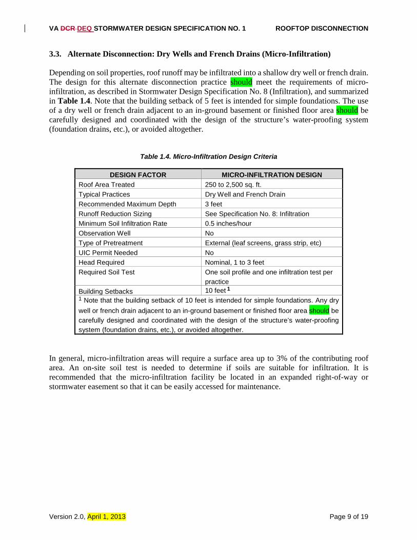
3.3. Alternate Disconnection: Dry Wells and French Drains (Micro-Infiltration) Depending on soil properties, roof runoff may be infiltrated into a shallow dry well or french drain. The design for this alternate disconnection practice should meet the requirements of micro-infiltration, as described in Stormwater Design Specification No. 8 (Infiltration), and summarized in Table 1.4. Note that the building setback of 5 feet is intended for simple foundations. The use of a dry well or french drain adjacent to an in-ground basement or finished floor area should be carefully designed and coordinated with the design of the structure’s water-proofing system (foundation drains, etc.), or avoided altogether.
Table 1.4. Micro-Infiltration Design Criteria
DESIGN FACTOR MICRO-INFILTRATION DESIGN Roof Area Treated 250 to 2,500 sq. ft. Typical Practices Dry Well and French Drain Recommended Maximum Depth 3 feet Runoff Reduction Sizing See Specification No. 8: Infiltration Minimum Soil Infiltration Rate 0.5 inches/hour Observation Well No Type of Pretreatment External (leaf screens, grass strip, etc) UIC Permit Needed No Head Required Nominal, 1 to 3 feet Required Soil Test One soil profile and one infiltration test per
practice Building Setbacks 10 feet 1 1 Note that the building setback of 10 feet is intended for simple foundations. Any dry well or french drain adjacent to an in-ground basement or finished floor area should be carefully designed and coordinated with the design of the structure’s water-proofing system (foundation drains, etc.), or avoided altogether.
In general, micro-infiltration areas will require a surface area up to 3% of the contributing roof area. An on-site soil test is needed to determine if soils are suitable for infiltration. It is recommended that the micro-infiltration facility be located in an expanded right-of-way or stormwater easement so that it can be easily accessed for maintenance.
VA DCR DEQ STORMWATER DESIGN SPECIFICATION NO. 1 ROOFTOP DISCONNECTION
Version 2.0, April 1, 2013 Page 10 of 19
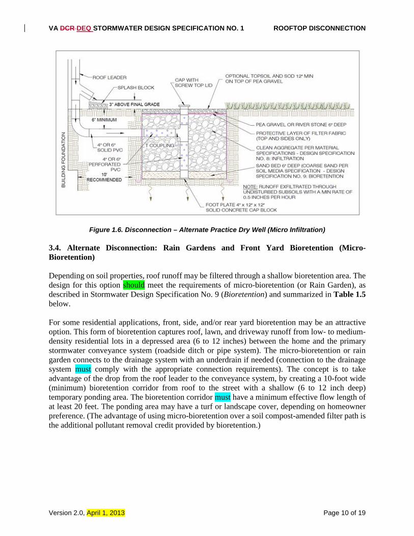
Figure 1.6. Disconnection – Alternate Practice Dry Well (Micro Infiltration) 3.4. Alternate Disconnection: Rain Gardens and Front Yard Bioretention (Micro-Bioretention) Depending on soil properties, roof runoff may be filtered through a shallow bioretention area. The design for this option should meet the requirements of micro-bioretention (or Rain Garden), as described in Stormwater Design Specification No. 9 (Bioretention) and summarized in Table 1.5 below. For some residential applications, front, side, and/or rear yard bioretention may be an attractive option. This form of bioretention captures roof, lawn, and driveway runoff from low- to medium-density residential lots in a depressed area (6 to 12 inches) between the home and the primary stormwater conveyance system (roadside ditch or pipe system). The micro-bioretention or rain garden connects to the drainage system with an underdrain if needed (connection to the drainage system must comply with the appropriate connection requirements). The concept is to take advantage of the drop from the roof leader to the conveyance system, by creating a 10-foot wide (minimum) bioretention corridor from roof to the street with a shallow (6 to 12 inch deep) temporary ponding area. The bioretention corridor must have a minimum effective flow length of at least 20 feet. The ponding area may have a turf or landscape cover, depending on homeowner preference. (The advantage of using micro-bioretention over a soil compost-amended filter path is the additional pollutant removal credit provided by bioretention.)
VA DCR DEQ STORMWATER DESIGN SPECIFICATION NO. 1 ROOFTOP DISCONNECTION
Version 2.0, April 1, 2013 Page 11 of 19
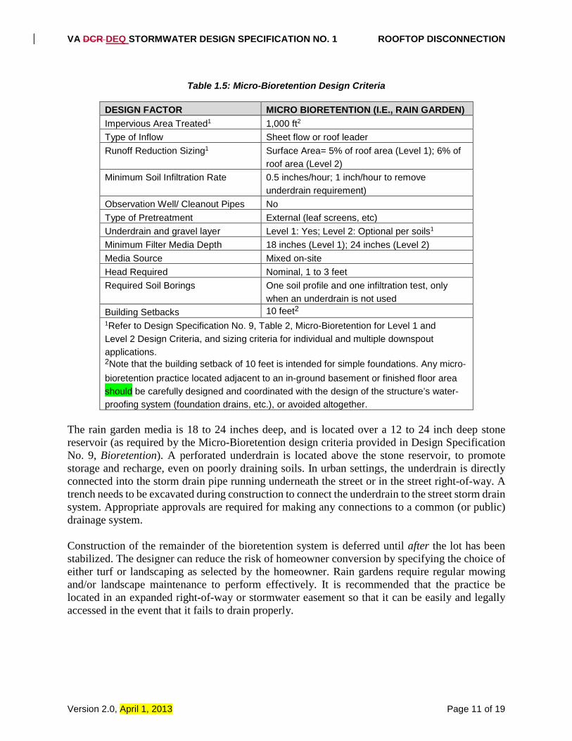
Table 1.5: Micro-Bioretention Design Criteria
DESIGN FACTOR MICRO BIORETENTION (I.E., RAIN GARDEN) Impervious Area Treated1 1,000 ft2 Type of Inflow Sheet flow or roof leader Runoff Reduction Sizing1 Surface Area= 5% of roof area (Level 1); 6% of
roof area (Level 2) Minimum Soil Infiltration Rate 0.5 inches/hour; 1 inch/hour to remove
underdrain requirement) Observation Well/ Cleanout Pipes No Type of Pretreatment External (leaf screens, etc) Underdrain and gravel layer Level 1: Yes; Level 2: Optional per soils1 Minimum Filter Media Depth 18 inches (Level 1); 24 inches (Level 2) Media Source Mixed on-site Head Required Nominal, 1 to 3 feet Required Soil Borings One soil profile and one infiltration test, only
when an underdrain is not used Building Setbacks 10 feet2 1Refer to Design Specification No. 9, Table 2, Micro-Bioretention for Level 1 and Level 2 Design Criteria, and sizing criteria for individual and multiple downspout applications. 2Note that the building setback of 10 feet is intended for simple foundations. Any micro-bioretention practice located adjacent to an in-ground basement or finished floor area should be carefully designed and coordinated with the design of the structure’s water-proofing system (foundation drains, etc.), or avoided altogether.
The rain garden media is 18 to 24 inches deep, and is located over a 12 to 24 inch deep stone reservoir (as required by the Micro-Bioretention design criteria provided in Design Specification No. 9, Bioretention). A perforated underdrain is located above the stone reservoir, to promote storage and recharge, even on poorly draining soils. In urban settings, the underdrain is directly connected into the storm drain pipe running underneath the street or in the street right-of-way. A trench needs to be excavated during construction to connect the underdrain to the street storm drain system. Appropriate approvals are required for making any connections to a common (or public) drainage system. Construction of the remainder of the bioretention system is deferred until after the lot has been stabilized. The designer can reduce the risk of homeowner conversion by specifying the choice of either turf or landscaping as selected by the homeowner. Rain gardens require regular mowing and/or landscape maintenance to perform effectively. It is recommended that the practice be located in an expanded right-of-way or stormwater easement so that it can be easily and legally accessed in the event that it fails to drain properly.
VA DCR DEQ STORMWATER DESIGN SPECIFICATION NO. 1 ROOFTOP DISCONNECTION
Version 2.0, April 1, 2013 Page 12 of 19
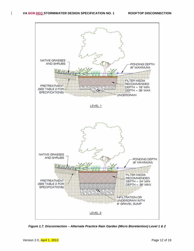
Figure 1.7. Disconnection – Alternate Practice Rain Garden (Micro Bioretention) Level 1 & 2
VA DCR DEQ STORMWATER DESIGN SPECIFICATION NO. 1 ROOFTOP DISCONNECTION
Version 2.0, April 1, 2013 Page 13 of 19
3.5. Alternate Disconnection: Rain Tanks and Cisterns This form of disconnection must conform to the design requirements outlined in Stormwater Design Specification No. 6: Rainwater Harvesting). The actual runoff reduction rate for a particular design can be determined using the design spreadsheet referenced in Specification No. 6: Rainwater Harvesting. The runoff reduction rates for rain tanks and cisterns depends on their storage capacity and ability to draw down water between storms for reuse as potable water, grey-water or for irrigation. All devices should have a suitable overflow area to route extreme flows into the next treatment practice or the stormwater conveyance system. 3.6. Alternate Disconnection: Stormwater Planter (Urban Bioretention) This form of disconnection must conform to the design requirements for stormwater planters, as outlined in Appendix A (Urban Bioretention) of Stormwater Design Specification No. 9 (Bioretention). Foundation planters are a useful option to disconnect and treat rooftop runoff, particularly in ultra-urban areas. They consist of confined planters that store and/or infiltrate runoff in a soil bed to reduce runoff volumes and pollutant loads. Stormwater planters combine an aesthetic landscaping feature with a functional form of stormwater treatment. Stormwater planters generally receive runoff from adjacent rooftop downspouts and are landscaped with plants that are tolerant to periods of both drought and inundation. The two basic design variations for stormwater planters are the infiltration planter and the filter planter. An infiltration planter filters rooftop runoff through soil in the planter followed by infiltration into soils below the planter. The recommended minimum depth is 24 inches, with the shape and length determined by architectural considerations. The planter should be sized to temporarily store at least 1/2-inch of runoff from the contributing rooftop area in a reservoir above the planter bed. Infiltration planters should be placed at least 10 feet away from a building to prevent possible flooding or basement seepage damage. A filter planter has an impervious liner on the bottom. The minimum planter depth is 18 inches, with the shape and length determined by architectural considerations. Runoff is temporarily stored in a reservoir located above the planter bed. Overflow pipes are installed to discharge runoff when maximum ponding depths are exceeded, to avoid water spilling over the side of the planter. In addition, an underdrain is used to carry runoff to the storm sewer system. Since a filter planter is self-contained and does not infiltrate into the ground, it can be installed right next to a building. All planters should be placed at grade level or above ground. They should be sized to allow captured runoff to drain out within four hours after a storm event. Plant materials should be capable of withstanding moist and seasonally dry conditions. Planting media should have an infiltration rate of at least 2 inches per hour. The sand and gravel on the bottom of the planter should have a minimum infiltration rate of 5 inches per hour. The planter can be constructed of stone, concrete, brick, wood or other durable material. If treated wood is used, care should be taken so that trace metals and creosote do not leach out of the planter.
SECTION 4: REGIONAL AND SPECIAL CASE DESIGN ADAPTATIONS
VA DCR DEQ STORMWATER DESIGN SPECIFICATION NO. 1 ROOFTOP DISCONNECTION
Version 2.0, April 1, 2013 Page 14 of 19
4.1 Karst Terrain Rooftop disconnection is strongly recommended in karst areas for most residential lots greater than 6,000 square feet, particularly if it can be combined with a secondary micro-practice to increase small scale runoff volume reduction. The discharge point from the disconnection should extend at least 15 feet from any building foundations. Rooftop disconnection is also recommended for commercial sites that are not likely to be stormwater hotspots. 4.2 Coastal Plain Terrain Disconnection is strongly recommended in the coastal plain for rooftops or other impervious areas on most residential lots greater than 6,000 square feet. Since this practice is especially suited to the coastal plain, the VSMP Authority may elect to encourage the use of an alternate disconnection practice, particularly if it can be combined with a secondary micro-practice to increase small-scale runoff volume reduction while reducing the overall footprint of simple disconnection. The disconnection corridor should have a minimum slope of 1% in the first 10 feet and a minimum 2 feet of vertical separation from the water table.
SECTION 5: CONSTRUCTION
5.1. Construction Sequence for Simple Impervious Disconnection The construction of impervious cover disconnection will occur after all of the impervious areas have been constructed and adjacent pervious areas have been stabilized. This usually includes the construction of the individual residences and driveways, and the stabilization of the yards. The design of the practices may require adjustments to fit exact driveway locations, structure rooflines and downspout locations. The VSMP Authority should enact provisions similar to the Erosion Control Program “Agreements in Lieu of Plans,” to include all the appropriate parties – site operator, home builder, and homeowner, etc. – to ensure that the residential disconnection practices are installed and stabilized in accordance with the approved plans. To the extent practicable, the construction of alternate disconnection practices should follow the construction guidance, checklists, and inspections outlined for the micro-scale versions of the individual runoff reduction practices (soil amendments, micro-infiltration, micro-bioretention, rainwater harvesting, and urban planters). The following are general procedures for implementing simple and, when applicable, alternate disconnection practices: • Before construction begins, general boundaries of the disconnection practice should be
identified on the site/plot plan, and clearly marked on the site. • Minimize construction traffic (staging of materials, contractor parking, etc.), especially during
foundation construction. • Stockpile existing topsoil if it is stripped in preparation for foundation construction. • Any grading to establish filter or flow paths should be achieved with lightweight equipment
VA DCR DEQ STORMWATER DESIGN SPECIFICATION NO. 1 ROOFTOP DISCONNECTION
Version 2.0, April 1, 2013 Page 15 of 19
• Divert downspouts until the filter path is completely stabilized. (It may be appropriate to use stabilization matting (e.g., EC-3 or an equivalent) regardless of slope to encourage thick turf cover growth.
5.2 Construction Inspection Construction inspection is critical to ensure that the minimal slope away from the structure is maintained. Construction of the disconnection practices should occur after most of the site work has been completed and the house or building structure has been enclosed. Therefore, especially in residential developments, the construction of the disconnection practice may be done by the builder and/or the residential landscape contractor that is responsible for the final lot grading and stabilization. The specific locations of the practices may change as a result of the actual downspout or driveway locations. It is important that the contractor and the inspector be able to adapt the original design of the disconnection to the new location and achieve the same overall performance goals in terms of geometry, volume, and impervious areas treated. The as-built survey or certification should document that the disconnection practices have (1) been installed either consistent with the plan or as adapted to fit the specific site conditions, and (2) been accepted by the homeowners. The GPS coordinates should be logged for any of these practices, upon facility acceptance, and submitted for entry into the local BMP maintenance tracking database. An example construction phase inspection checklist for simple disconnection can be found at the end of this design specification. Construction inspection recommendations for alternate disconnection practices can be found in the BMP Specifications for those practices.
SECTION 6: MAINTENANCE 6.1 Maintenance Agreements The Virginia Stormwater Management Program (VSMP) Regulations (4 VAC 50-60-112) specify the circumstances under which a maintenance agreement must be executed between the owner and the VSMP authority, and sets forth inspection requirements, compliance procedures if maintenance is neglected, notification of the local program upon transfer of ownership, and right-of-entry for local program personnel. • All rooftop disconnection and supplementary treatment devices that are intended to provide
for compliance with the VSMP regulations must be noted on the deed of record and covered by a deed restriction or other mechanism which has already been executed and is enforceable by the VSMP authority, to help ensure that downspouts remain disconnected, treatment units are maintained and filtering/infiltrating areas are not converted or disturbed.
• The legal mechanism should, if possible, grant authority for local agencies to access the property for inspection or corrective action.
• Homeowners must be provided a simple document that explains the purpose and routine maintenance needs of these BMPs.
VA DCR DEQ STORMWATER DESIGN SPECIFICATION NO. 1 ROOFTOP DISCONNECTION
Version 2.0, April 1, 2013 Page 16 of 19
6.2 Maintenance Inspections Long term inspections of simple and alternate disconnection practices can be accomplished through a property owner inspection program developed by the VSMP Authority. Inspections should check to ensure that: • Flows through the disconnection filter or flow path are not channelizing or short circuiting; • Debris and sediment does not build up at the top of the flow path; • Foot or vehicular traffic does not compromise the gravel diaphragm or energy dissipater; • Scour and erosion do not occur within the flow path; • Sediments and decomposed leaves or debris are cleaned out of the energy dissipater; and • Vegetative density exceeds a 90% cover in the filter or flow path. An example maintenance inspection checklist for Simple Rooftop Disconnection can be accessed in Appendix C of Chapter 9 of the Virginia Stormwater Management Handbook (2013). Maintenance checklists for the alternate micro-scale practices can be found with their respective maintenance checklists in the same Appendix C.
VA DCR DEQ STORMWATER DESIGN SPECIFICATION NO. 1 ROOFTOP DISCONNECTION
Version 2.0, April 1, 2013 Page 17 of 19
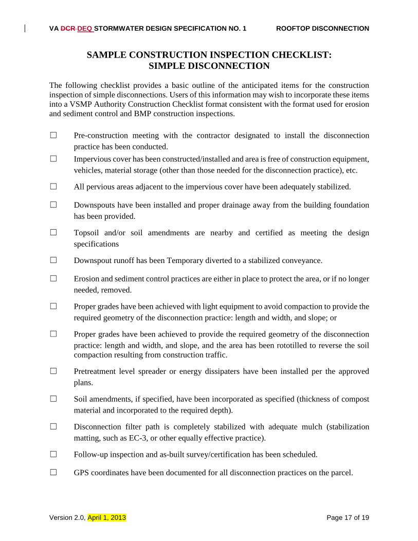
SAMPLE CONSTRUCTION INSPECTION CHECKLIST: SIMPLE DISCONNECTION
The following checklist provides a basic outline of the anticipated items for the construction inspection of simple disconnections. Users of this information may wish to incorporate these items into a VSMP Authority Construction Checklist format consistent with the format used for erosion and sediment control and BMP construction inspections. ☐ Pre-construction meeting with the contractor designated to install the disconnection
practice has been conducted. ☐ Impervious cover has been constructed/installed and area is free of construction equipment,
vehicles, material storage (other than those needed for the disconnection practice), etc.
☐ All pervious areas adjacent to the impervious cover have been adequately stabilized.
☐ Downspouts have been installed and proper drainage away from the building foundation has been provided.
☐ Topsoil and/or soil amendments are nearby and certified as meeting the design specifications
☐ Downspout runoff has been Temporary diverted to a stabilized conveyance.
☐ Erosion and sediment control practices are either in place to protect the area, or if no longer needed, removed.
☐ Proper grades have been achieved with light equipment to avoid compaction to provide the required geometry of the disconnection practice: length and width, and slope; or
☐ Proper grades have been achieved to provide the required geometry of the disconnection practice: length and width, and slope, and the area has been rototilled to reverse the soil compaction resulting from construction traffic.
☐ Pretreatment level spreader or energy dissipaters have been installed per the approved plans.
☐ Soil amendments, if specified, have been incorporated as specified (thickness of compost material and incorporated to the required depth).
☐ Disconnection filter path is completely stabilized with adequate mulch (stabilization matting, such as EC-3, or other equally effective practice).
☐ Follow-up inspection and as-built survey/certification has been scheduled.
☐ GPS coordinates have been documented for all disconnection practices on the parcel.

VA DCR DEQ STORMWATER DESIGN SPECIFICATION NO. 1 ROOFTOP DISCONNECTION
Version 2.0, April 1, 2013 Page 18 of 19
VA DCR DEQ STORMWATER DESIGN SPECIFICATION NO. 1 ROOFTOP DISCONNECTION
Version 2.0, April 1, 2013 Page 19 of 19
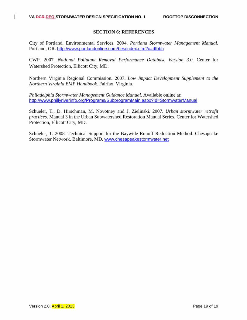
SECTION 6: REFERENCES City of Portland, Environmental Services. 2004. Portland Stormwater Management Manual. Portland, OR. http://www.portlandonline.com/bes/index.cfm?c=dfbbh CWP. 2007. National Pollutant Removal Performance Database Version 3.0. Center for Watershed Protection, Ellicott City, MD. Northern Virginia Regional Commission. 2007. Low Impact Development Supplement to the Northern Virginia BMP Handbook. Fairfax, Virginia. Philadelphia Stormwater Management Guidance Manual. Available online at: http://www.phillyriverinfo.org/Programs/SubprogramMain.aspx?Id=StormwaterManual Schueler, T., D. Hirschman, M. Novotney and J. Zielinski. 2007. Urban stormwater retrofit practices. Manual 3 in the Urban Subwatershed Restoration Manual Series. Center for Watershed Protection, Ellicott City, MD. Schueler, T. 2008. Technical Support for the Baywide Runoff Reduction Method. Chesapeake Stormwater Network. Baltimore, MD. www.chesapeakestormwater.net